Rational Unified Process(统一软件开发过程): Overview
The Rational Unified Process® or RUP(统一软件开发过程)® product is a software engineering process. It provides a disciplined approach to assigning tasks and responsibilities within a development organization. Its goal is to ensure the production of high-quality software that meets the needs of its end users within a predictable schedule and budget.
The preceding figure illustrates the overall architecture of the RUP, which has two dimensions:
- The horizontal axis represents time and shows the lifecycle aspects of the process as it unfolds. This first dimension illustrates the dynamic aspect of the process as it’s enacted and is expressed in terms of phases, iterations, and milestones.
- The vertical axis represents disciplines that logically group activities by nature. This second dimension portrays the static aspect of the process-how it’s described in terms of process components, disciplines, activities, workflows, artifacts, and roles (see Key Concepts).
The graph shows how the emphasis varies over time. For example, in early iterations you spend more time on requirements; in later iterations you spend more time on implementation.
About Rational Unified Process(统一软件开发过程)
Topics
Version information
© Copyright IBM Corp. 1987, 2004
All Rights Reserved
About this configuration
The Classic RUP(统一软件开发过程) template configuration recreates the RUP configuration that has been delivered over the years.
Classic RUP is useful as a published knowledge base that covers the gamut of RUP processes and practices. As such it is published and delivered with the RUP installation (either as a point product or in the suites). For Rational Suites users, it is the default location for Extended Help, context sensitive process guidance that is available from Rational tools’ Help menus. Very large or complex projects wishing to create RUP configurations for their purposes will find the Classic RUP configuration the most useful starting point for initial customized versions of the process. They will likely wish to harvest knowledge part way through these projects and use the Rational Process Workbench to create plug-ins that even more tightly align the process with their needs.
The following RUP plug-ins are included in this configuration:
- Formal Resources
- Informal Resources
The following process components are included as part of this configuration:
- Lifecycle
- Classic RUP
- Disciplines
- Process Components
- Tools
- Tool Mentors
- Rational Unified Process
- RUP Builder
- Rational Process Workbench
- Rational Administrator
- Rational Suite AnalystStudio
- Rational ClearCase
- Rational ClearQuest
- Rational ProjectConsole
- Rational PurifyPlus
- Rational QualityArchitect
- Rational RequisitePro
- Rational Robot
- Rational Rose
- Rational Rose RealTime
- Rational SoDA
- Rational TestManager
- Rational Test RealTime
- Rational TestFactory
- Rational XDE Developer(开发人员) - Java Platform Edition
- Rational XDE Developer - .NET Edition
- Tool Mentors
Legal statement
Browser support
Note 1: RUP does not currently support Netscape Navigator 6.x.
Note 2: Some versions of Microsoft Internet Explorer 4.x and Netscape Navigator 4.x may not be able to display all pages in RUP. To obtain the latest version of your browser, click on the appropriate icon.


Rational Unified Process(统一软件开发过程): Concepts Overview
The following is a summary of all concepts that are part of this RUP(统一软件开发过程) configuration.
- Developing Component(构件) Solutions
- Developing e-business Solutions
- Usability Engineering
- Tailoring a Process for a Small Project
- Agile Practices and RUP
- Disciplines
- Business Modeling
- Requirements
- Architecture
- Software Architecture
- Layering
- Prototypes
- Web Architecture(架构) Patterns
- Design and Implementation(实现) Mechanisms
- Concurrency
- Distribution Patterns
- Events and Signals
- Analysis Mechanisms
- Logical View
- Process View
- Implementation View
- Deployment View
- Component
- Structured Class
- Representing Interfaces to External Systems
- Design
- Implementation
- Assessment
- Production
- Management
- Project Management
- Project Environment
- Configuration & Change Management
- Iteration
- Evaluating Quality
- Estimating Project Effort
- Risk
- Metrics
- Implementing a Process in a Project
- Agile Practices and RUP
- Mentoring
- The Underlying Model of the Rational Unified Process
- Pilot Project
- Effect of Implementing a Process
- RUP Tailoring
- Tailoring a Process for a Small Project
- Development Environment
- Process Quality
- Tools
Rational Unified Process(统一软件开发过程): Guidelines Overview
The following is a summary of all guidelines that are part of this RUP(统一软件开发过程) configuration.
- Installing and Customizing Microsoft Word Templates
- Installing and Customizing Microsoft Word Templates (Informal Set)
- Disciplines
- Business Modeling
- Business Use-Case Modeling
- Actor-Generalization in the Business Use-Case Model
- Business Use-Case Model
- Communicate-Association in the Business Use-Case Model
- Extend-Relationship in the Business Use-Case Model
- Include-Relationship in the Business Use-Case Model
- Use-Case Diagram in the Business Use-Case Model
- Use-Case-Generalization in the Business Use-Case Model
- Business Actor
- Business Use Case
- Activity Diagram in the Business Use-Case Model
- Business Analysis Modeling
- Business Analysis Model
- Diagrams in the Business Analysis Model
- Association in the Business Analysis Model
- Aggregation in the Business Analysis Model
- Generalization in the Business Analysis Model
- Going from Business Models to Systems
- Business Event
- Business Use-Case Realization
- Business Worker
- Business Entity
- Business System
- Business Architecture(架构) Document
- Assessment Workshop
- Brainstorming and Idea Reduction
- Pareto Diagrams
- Fishbone Diagrams
- Business Actor
- Business Use Case
- Business Goal
- Use-Case Diagram in the Business Use-Case Model
- Communicate-Association in the Business Use-Case Model
- Business Use-Case Model
- Include-Relationship in the Business Use-Case Model
- Extend-Relationship in the Business Use-Case Model
- Use-Case-Generalization in the Business Use-Case Model
- Business Architecture Document
- Going from Business Models to Systems
- Activity Diagram in the Business Use-Case Model
- Business Analysis Model
- Business Analysis Modeling Workshop
- Role Playing
- Aggregation in the Business Analysis Model
- Generalization in the Business Analysis Model
- Association in the Business Analysis Model
- Business Use-Case Realization
- Diagrams in the Business Analysis Model
- Business Worker
- Business Entity
- Business Vision
- Target-Organization Assessment
- Business Rules
- Business Use-Case Modeling
- Requirements
- Requirements w/ Use Cases
- Software Requirements(需求) Specification
- Supplementary Specifications - Informal Representation
- Use-Case Model
- Use-Case Diagram
- Communicate-Association
- Actor-Generalization
- Use-Case Generalization
- Include-Relationship
- Extend-Relationship
- Use-Case Package
- Use Case
- Activity Diagram in the Use-Case Model
- Actor
- Requirements Management
- Software Requirements Specification
- Brainstorming and Idea Reduction
- Storyboarding
- Use-Case Workshop
- Requirements Management Plan
- Important Decisions in Requirements
- Stakeholder Requests - Informal Representation
- Interviews
- Requirements Workshop
- Storyboard
- Requirements w/ Use Cases
- Architecture
- Concurrency
- Representing Interfaces to External Systems
- Reverse-engineering Relational Databases
- Layering
- Software Architecture Document
- Association
- Aggregation
- Generalization
- Import Dependency in Design
- Subscribe-Association
- Class Diagram
- Communication Diagram
- Sequence Diagram
- Statechart Diagram
- Design Model
- Design Class
- Testing and Evaluating Classes
- Building Web Applications with the UML
- Interface
- Design Package
- Design Subsystem
- Capsule
- Use-Case Realization
- Test Design
- Design
- Implementation
- Assessment
- Reviews
- Test
- Reviews
- Test Plan
- Iteration Assessment - Informal Representation
- Status Assessment - Informal Representation
- Review Levels
- Review Record - Informal Representation
- Production
- Management
- Project Management
- Project Environment
- Reviews
- Estimating Effort Using the Wide-Band Delphi Technique
- Process Tailoring Practices
- Process Discriminants
- Development Case
- Important Decisions in Analysis & Design
- Important Decisions in Business Modeling
- Important Decisions in Configuration & Change Management
- Important Decisions in Environment
- Important Decisions in Deployment
- Important Decisions in Implementation
- Important Decisions in Project Management
- Important Decisions in Requirements
- Important Decisions in Test
- Classifying Artifacts
- Development Case Workshop
- Iteration Plan
- Metrics
- Software Development Plan
- Risk List
- Risk List - Informal Representation
- Business Case
- Alternative Representations of Document Artifacts
- Review Levels
Glossary(术语表)(Test) - Rational Unified Process(统一软件开发过程)
A
- ABC
- ABM
- abstract
-
Of or relating to a subject in the abstract without practical purpose or intention. Not applied or practical; theoretical. Considered apart from concrete existence. Contrast: concrete. See: abstract class.
-
A concept or idea not associated with any specific instance. Synonym: abstraction.
-
A summary of the main points of an argument or theory. Synonyms: outline, synopsis.
- abstract class
-
 A class that provides common behavior across a set of subclasses but is not itself designed to have instances. An abstract class represents a concept; classes derived from it represent implementations of the concept. See also: base class. Contrast: concrete class.
 - abstraction
-
The creation of a view or model that suppresses unnecessary details to focus on a specific set of details of interest
-
The essential characteristics of an entity that distinguish it from all other kinds of entities. An abstraction defines a boundary relative to the perspective of the viewer.
- acceptance
-
An action by which the customer accepts ownership of software products as a partial or complete performance of a contract.
- access modifier
-
A keyword that controls access to a class, method, or attribute. The access modifiers in Java are public, private, protected, and package, which is the default.
- accessor methods
-
Methods that an object provides to define the interface to its instance variables. The accessor method to return the value of an instance variable is called a get method or getter method, and the mutator method to assign a value to an instance variable is called a set method or setter method.
- ACL
-
Access control list.
- action
-
The specification of an executable statement that forms an abstraction of a computational procedure. An action typically results in a change in the state of the system, and can be realized by sending a message to an object or modifying a link or a value of an attribute.
- action sequence
-
An expression that resolves to a sequence of actions.
- action state
-
A state that represents the execution of an atomic action, typically the invocation of an operation.
- activation
-
The execution of an action.
- active class
-
A class representing a thread of control in the system.
-
A class whose instances are active objects. See: active object.
- active object
-
An object that owns a thread and can initiate control activity. An instance of active class.
- Active Server Page (ASP)
-
Active Server Page (Microsoft(R)), a technology mechanism for providing dynamic behavior to web applications.
- activity
-
A unit of work a role may be asked to perform.
- Activity(活动)-Based Costing (ABC)
-
A methodology that measures the cost and performance of activities, resources, and cost objects. Resources are assigned to activities, then activities are assigned to cost objects based on their use. Activity based costing recognizes the causal relationships of cost drivers to activities.
- Activity-Based Management (ABM)
-
The broad discipline that focuses on achieving customer value and company profit by way of the management of activities. It draws on activity-based costing as a major source of information.
- activity graph
-
A special case of a state machine that is used to model processes involving one or more classifiers. Contrast: statechart diagram . Synonym: activity diagram.
- actor (class)
-
Defines a set of actor instances, in which each actor instance plays the same role in relation to the system.
-
A coherent set of roles that users of use cases play when interacting with these use cases. An actor has one role for each use case with which it communicates.
- actor (instance)
-
Someone or something, outside the system that interacts with the system.
- actor generalization
-
An actor generalization from an actor class (descendant) to another actor class (ancestor) indicates that the descendant inherits the role the ancestor can play in a use case.
- actual parameter
-
Synonym: argument.
- Advanced Program-to-Program Communication (APPC)
-
A communication protocol used primarily in IBM environments.
- aggregate (class)
-
A class that represents the “whole” in an aggregation (whole-part) relationship. See: aggregation.
- aggregation
-
An association that models a whole-part relationship between an aggregate (the whole) and its parts.
-
A special form of association that specifies a whole-part relationship between the aggregate (whole) and a component part. See: composition.
- American Standard Code for Information Interchange (ASCII)
-
American standard code for information interchange. The 8-bit character encoding scheme used by most PCs and UNIX systems. It supersedes an earlier 7-bit ASCII standard.
- analysis
-
The part of the software development process whose primary purpose is to formulate a model of the problem domain. Analysis focuses on what to do; design focuses on how to do it. See: design.
- analysis & design
-
(general) activities during which strategic and tactical decisions are made to meet the required functional and quality requirements of a system. See also: Design Model.
-
A discipline in the Unified Process, whose purpose is to show how the system’s *use case*s will be realized in implementation.
- analysis class
-
An abstraction of a role played by a design element in the system, typically within the context of a use-case realization. Analysis classes may provide an abstraction for several roles, representing the common behavior of those roles. Analysis classes typically evolve into one or more design elements; for example, design *class*es and/or *capsule*s, or design *subsystem*s.
- analysis mechanism
-
An architectural mechanism used early in the design process, during the period of discovery when key classes and subsystems are being identified. Typically analysis mechanisms capture the key aspects of a solution in a way that is implementation independent. Analysis mechanisms are usually unrelated to the problem domain, but instead are “computer science” concepts. They provide specific behaviors to a domain-related class or component, or correspond to the implementation of cooperation between classes and/or components. They may be implemented as a framework. Examples include mechanisms to handle persistence, inter-process communication, error or fault handling, notification, and messaging, to name a few.
- analysis model
-
An object model that serves as an abstraction of the design model; provides the initial definition of the realization of the use cases.
- analysis pattern
-
[FOW97a] speaks of analysis patterns as,
“[…] groups of concepts that represent a common construction in business modeling. It may be relevant to only one domain, or it may span many domains.”
Therefore, in this reference, the vocabulary of the domain does intrude into the description of the pattern. There is no reason why the definition in [FOW97a] should not be extended to domains other than business modeling. Another aspect of an analysis pattern is that it is an abstract, conceptual template, intended (through binding as with any pattern) for instantiation in an analysis model, which will then need further refinement through design. The scale of an analysis pattern can vary widely, though those presented in [FOW97a] are medium in scale, and would compose to form analysis models for entire applications.
- analysis time
-
Refers to something that occurs during an analysis phase of the software development process. See: design time, modeling time.
- analyst
-
Member of the project team who is responsible for eliciting and interpreting the stakeholder needs, and communicating those needs to the entire team.
- API
- APPC
- applet
-
A Java program designed to run within a Web browser. Contrast: application.
- application
-
An act of putting to use (new techniques): an act of applying techniques.
-
Function and industry-relevant software that is determined by a particular business (for example, banking, aerospace, stock brokerage, insurance, accounting, inventory).
-
In Java programming, a self-contained, stand-alone Java program that includes main() method. Contrast: applet.
- Application Programming Interface(接口) (API)
-
A software interface that enables applications to communicate with each other. An API is the set of programming language constructs or statements that can be coded in an application program to obtain the specific functions and services provided by an underlying operating system or service program.
- architectural baseline
-
The baseline at the end of the Elaboration phase, at which time the foundation structure and behavior of the system is stabilized.
- architectural mechanism
-
Architectural mechanisms represent common concrete solutions to frequently encountered problems. They may be patterns of structure, patterns of behavior, or both. In the Rational Unified Process (RUP), architectural mechanism is used as an umbrella term for analysis mechanism, design mechanism, and implementation mechanism.
- architectural pattern
-
[BUS96] defines an architectural pattern as:
“An architectural pattern expresses a fundamental structural organization schema for software systems. It provides a set of predefined subsystems, specifies their responsibilities, and includes rules and guidelines for organizing the relationships between them.”
This is the interpretation we use in the RUP(统一软件开发过程). To elaborate a little: an architectural pattern is a pattern (that is, a solution template) at a particular scale, and is a template for concrete software architectures. It deals in system-wide properties and, typically, subsystem-scale (not class level) relationships. Architectural patterns seem, by their nature, not to be application domain dependent-the vocabulary of a particular domain seems not to intrude into the description of the pattern-although there is no reason in principle why architectural patterns cannot become specialized in this way. Compare with analysis pattern. The Software Architecture(软件架构) Document(软件架构文档) will present the architectural patterns used in the system.
- architectural view
-
A view of the system architecture from a given perspective. Focuses primarily on structure, modularity, essential components, and the main control flows.
- architecture
-
The highest level concept of a system in its environment, according to IEEE. The architecture of a software system (at a given point in time) is its organization or structure of significant components interacting through *interface*s, those components being composed of successively smaller components and interfaces.
-
The organizational structure of a system. An architecture can be recursively decomposed into parts that interact through interfaces, relationships that connect parts, and constraints for assembling parts. Parts that interact through interfaces include classes, components and subsystems.
- architecture, executable
-
See: executable architecture.
- argument
-
A binding for a parameter that resolves to a run-time instance. Synonym: actual parameter. Contrast: parameter.
-
A data element, or value, included as a parameter in a method call. Arguments provide additional information that the called method can use to perform the requested operation.
- artifact
-
(1) A piece of information that: 1) is produced, modified, or used by a process, 2) defines an area of responsibility, and 3) is subject to version control. An artifact can be a model, a model element, or a document. A document can enclose other documents.
-
A physical piece of information that is used or produced by a software development process. Examples of Artifacts include models, source files, scripts, and binary executable files. An artifact may constitute the implementation of a deployable component. Synonym: product. Contrast: component.
- artifact guidelines
-
A description of how to work with a particular artifact, including how to create and revise the artifact.
- artifact set
-
A set of related artifacts which help to present one aspect of the system. Artifact(工件) sets cut across disciplines, as several artifacts are used in a number of disciplines; for example, the Risk(风险) List(风险列表), the Software Architecture(架构) Document, and the Iteration(迭代) Plan(迭代计划).
- ASCII
- ASP
-
See: active server page
- assertion
-
A logical expression specifying a program state that must exist or a set of conditions that program variables must satisfy at a particular point during program execution.
- association
-
A relationship that models a bi-directional semantic connection among instances.
-
The semantic relationship between two or more classifiers that specifies connections among their instances.
- association class
-
A model element that has both association and class properties. An association class can be seen as an association that also has class properties, or as a class that also has association properties.
- association end
-
The endpoint of an association, which connects the association to a classifier.
- asynchronous action
-
A request where the sending object does not pause to wait for results. Contrast: synchronous action.
- attack
-
A planned and methodical attempt to break or otherwise circumvent the normal operation of a running computer software program. Often malicious in nature, the concept of attacking computer software originated in the software hacker (A.K.A cracker) community whose members use various techniques to attack software systems, typically to circumvent security software and gain illegal entry to a host system. Examples of recognized attack techniques include buffer overflow, denial of service, resource constraint and Trojan horse. This term has subsequently been adopted by computer software testing professionals in discussing the methods by which they might expose potential bugs in a software system.
- attribute
-
An attribute defined by a class represents a named property of the class or its objects. An attribute has a type that defines the type of its instances.
-
A feature within a classifier that describes a range of values that instances of the classifier may hold.
B
- base class
- A class from which other classes or beans are derived. A base class may itself be derived from another base class. See: abstract class.
- baseline
- A reviewed and approved release of artifacts that constitutes an agreed basis for further evolution or development and that can be changed only through a formal procedure, such as change management and configuration control .
- BASIC
- Beginner’s all-purpose symbolic instruction code*,* a programming language. See: VB .
- bean
- A small component that can be used to build applications. See: JavaBean .
- beaninfo
- A companion class for a bean that defines a set of methods that can be accessed to retrieve information on the bean’s properties, events, and methods.
- behavior
- The observable effects of an operation or event, including its results.
- behavioral feature
- A dynamic feature of a model element , such as an operation or method .
- behavioral model aspect
- A model aspect that emphasizes the behavior of the instances in a system, including their methods , collaborations , and state histories.
- beta testing
- Pre-release testing in which a sampling of the intended customer base tries out the product.
- binary association
- An association between two classes . A special case of an n-ary association .
- binding
- The creation of a model element from a template by supplying arguments for the parameters of the template.
- boolean
- An enumeration whose values are true and false.
- boolean expression
- An expression that evaluates to a boolean value.
- boundary class
- A class used to model communication between the system’s environments and its inner workings.
- break point
- A point in a computer program where the execution will be halted.
- build
- An operational version of a system or part of a system that demonstrates a subset of the capabilities to be provided in the final product.
- business actor (class)
- Defines a set of business-actor instances, in which each business-actor instance plays the same role in relation to the business.
- business actor (instance)
- Someone or something, outside the business that interacts with the business.
- business analysis model
- An object model describing the realization of business use cases . Synonym: business object model.
- business architecture
- Business architecture is an organized set of elements with clear relationships to one another, which together form a whole defined by its functionality. The elements represent the organizational and behavioral structure of a business, and show abstractions of the key processes and structures of the business.
- business creation
- To perform business engineering where the goal is to create a new business process , a new line of business or a new organization.
- business engineering
- A set of techniques a company uses to design its business according to specific goals. Business engineering techniques can be used for both business reengineering, business improvement , and business creation .
- business entity
- A business entity represents a significant and persistent piece of information that is manipulated by business actors and business workers .
- business event
- A business event describes a significant occurrence in space and time, of importance to the business. Business events are used to signal between business processes and are usually associated with business entities .
- business goal
- A business goal is a requirement that must be satisfied by the business. Business goals describe the desired value of a particular measure at some future point in time and can therefore be used to plan and manage the activities of the business. Also see business objective .
- business improvement
- To perform business engineering where the work of change is local and does not span the entire business. It involves trimming costs and lead times and monitoring service and quality.
- business modeling
- Encompasses all modeling techniques you can use to visually model a business. These are a subset of the techniques you may use to perform business engineering .
- business objective
- The commonly-used term for high-level business goals . Because business objectives are usually abstract, they are difficult to measure and are therefore translated into more measurable lower-level business goals.
- business process
- A group of logically related activities that use the resources of the organization to provide defined results in support of the organization’s objectives. In the RUP, we define business processes using business use cases , which show the expected behavior of the business, and business use-case realizations , which show how that behavior is realized by business workers and business entities . See also: process .
- business process engineering
- See: business engineering .
- business reengineering
- To perform business engineering where the work of change includes taking a comprehensive view of the entire existing business and think through why you do what you do. You question all existing business processes and try to find completely new ways of reconstructing them to achieve radical improvements. Other names for this are business process reengineering (BPR) and process innovation.
- business rule
- A declaration of policy or condition that must be satisfied within the business. Business rules can be captured in models, in documents or in both.
- business strategy
- The business strategy defines the principles and goals for realizing the business idea. It consists of a collection of long-term business objectives that will ultimately result in the achievement of the business vision.
- business system
- A business system encapsulates a set of roles and resources that together fulfill a specific purpose, and defines a set of responsibilities with which that purpose can be achieved.
- business use-case (class)
- A business use case defines a set of business use-case instances, where each instance is a sequence of actions a business performs that yields an observable result of value to a particular business actor. A business use-case class contains all main, alternate workflows related to producing the “observable result of value”.
- business use-case (instance)
- A sequence of actions performed by a business that yields an observable result of value to a particular business actor.
- business use-case model
- A model of the business intended functions. The business use-case model is used as an essential input to identify roles and deliverables in the organization.
- business use-case package
- A business use-case package is a collection of business use cases, business actors, relationships, diagrams, and other packages; it is used to structure the business use-case model by dividing it into smaller parts.
- business use-case realization
- A business use-case realization describes how the workflow of a particular business use case is realized within the business analysis model, in terms of collaborating business objects.
- business worker
- A business worker represents a role or set of roles in the business. A business worker interacts with other business workers and manipulates business entities while participating in business use-case realizations .
C
- call
- An action state that invokes an operation on a classifier .
- call-level interface (CLI)
- A callable API for database access, which is an alternative to an embedded SQL application program interface. In contrast to embedded SQL, CLI does not require precompiling or binding by the user, but instead provides a standard set of functions to process SQL statements and related services at run time.
- capsule
- A specific design pattern which represents an encapsulated thread of control in the system. A capsule is a stereotyped class with a specific set of required and restricted associations and properties .
- capsule role
- Capsule roles represent a specification of the type of capsule that can occupy a particular position in a capsule’s collaboration or structure. Capsule roles are strongly owned by the container capsule and cannot exist independently of it. A capsule’s structural decomposition usually includes a network of collaborating capsule roles joined by connectors.
- cardinality
- The number of elements in a set. Contrast: multiplicity .
- CBD
- See: component-based development
- CCB
- See: change control board
- CDR
- See: critical design review
- CGI
- See: common gateway interface
- change control board (CCB)
- The role of the CCB is to provide a central control mechanism to ensure that every change request is properly considered, authorized and coordinated.
- change management
- The activity of controlling and tracking changes to artifacts . See also: scope management .
- Change Request(变更请求) (CR)
- A general term for any request from a stakeholder to change an artifact or process . Documented in the Change Request is information on the origin and impact of the current problem, the proposed solution, and its cost. See also: enhancement request, defect.
- checkpoints
- A set of conditions that well-formed artifacts of a particular type should exhibit. May also be stated in the form of questions which should be answered in the affirmative.
- child
- In a generalization relationship, the specialization of another element, the parent. See: subclass, subtype. Contrast: parent.
- class
- A description of a set of objects that share the same attributes, operations, methods, relationships, and semantics. A class may use a set of interfaces to specify collections of operations it provides to its environment. See: interface.
- class diagram
- A diagram that shows a collection of declarative (static) model elements, such as classes, types, and their contents and relationships.
- class hierarchy
- The relationships among classes that share a single inheritance. All Java classes inherit from the Object class.
- classifier
- A mechanism that describes behavioral and structural features. Classifiers include interfaces, classes, datatypes, and components.
- class library
- A collection of classes.
- class method
- See: method.
- CLI
- See: call-level interface.
- client
- A classifier that requests a service from another classifier. Contrast: supplier.
- client/server
- The model of interaction in distributed data processing where a program at one location sends a request to a program at another location and awaits a response. The requesting program is called a client, and the answering program is called a server.
- CM
- See: configuration management .
- COBOL
- Common Business Oriented Language
- cohesion
- The congenital union of components of the same kind that depend on one another. The act or state of sticking together; close union. Contrast: coupling.
- collaboration
- (1) Is a description of a collection of objects that interact to implement some behavior within a context. It describes a society of cooperating objects assembled to carry out some purpose.
- (2) It captures a more holistic view of behavior in the exchange of messages within a network of objects.
- (3) Collaborations show the unity of the three major structures underlying computation: data structure, control flow, and data flow.
- (4) A collaboration has a static and a dynamic part. The static part describes the roles that objects and links play in an instantiation of the collaboration. The dynamic part consists of one or more dynamic interactions that show message flow over time in the collaboration to perform computations. A collaboration may have a set of messages to describe its dynamic behavior.
- (5) A collaboration with messages is an interaction.
- The specification of how an operation or classifier, such as a use case, is realized by a set of classifiers and associations playing specific roles used in a specific way. The collaboration defines an interaction. See: interaction.
- collaboration diagram
- This term was changed to communication diagram in UML 2.0.
- column
- An attribute of a table in a database.
- COM
- Component(构件) object model (Microsoft). A software architecture from DEC and Microsoft, allowing interoperation between ObjectBroker and OLE (Object linking and embedding). Microsoft later evolved COM into DCOM.
- comment
- An annotation attached to an element or a collection of elements. A note has no semantics. Contrast: constraint.
- commit
- The operation that ends a unit of work to make permanent the changes it has made to resources (transaction or data).
- common gateway interface (CGI)
- A standard protocol through which a Web server can execute programs running on the server machine. CGI programs are executed in response to requests from Web client browsers.
- common object request broker architecture (CORBA)
- A middleware specification which defines a software bus-the Object Request Broker (ORB)-that provides the infrastructure.
- communicates-association
- An association between an actor class and a use case class, indicating that their instances interact. The direction of the association indicates the initiator of the communication (Unified Process convention).
- communication association
- In a deployment diagram an association between nodes that implies a communication. See: deployment diagram.
- communication diagram
- (1) Formerly named collaboration diagram, a communication diagram describes a pattern of interaction among objects; it shows the objects participating in the interaction by their links to each other and the messages they send to each other.
- (2) It is a class diagram that contains classifier roles and association roles rather than just classifiers and associations.
- (3) Communication diagrams and sequence diagrams both show interactions, but they emphasize different aspects. Sequence diagrams show time sequences clearly but do not show object relationships explicitly. Communication diagrams show object relationships clearly, but time sequences must be obtained from sequence numbers.
- A diagram that shows interactions organized around the structure of a model, using either classifiers and associations or instances and links. Unlike a sequence diagram, a communication diagram shows the relationships among the instances. Sequence diagrams and communication diagrams express similar information, but show it in different ways. See: sequence diagram.
- compile time
- Refers to something that occurs during the compilation of a software module. See: modeling time, run time.
- component
- A non-trivial, nearly independent, and replaceable part of a system that fulfills a clear function in the context of a well-defined architecture. A component conforms to and provides the realization of a set of interfaces.
- A modular, deployable, and replaceable part of a system that encapsulates implementation and exposes a set of interfaces. A component is typically specified by one or more classifiers (e.g., implementation classes) that reside on it, and may be implemented by one or more artifacts (e.g., binary, executable, or script files). Contrast: artifact.
- component-based development (CBD)
- The creation and deployment of software-intensive systems assembled from components as well as the development and harvesting of such components.
- component diagram
- A diagram that shows the organizations and dependencies among components.
- component model
- An architecture and an API that allows developers to define reusable segments of code that can be combined to create a program. VisualAge for Java uses the JavaBeans component model.
- composite [class]
- A class that is related to one or more classes by a composition relationship. See: composition.
- composite aggregation
- Synonym: composition.
- composite bean
- A bean that is composed of other beans. A composite bean can contain visual beans, nonvisual beans, or both. See also: bean.
- composite state
- A state that consists of either concurrent (orthogonal) substates or sequential (disjoint) substates. See: substate.
- composite substate
- A substate that can be held simultaneously with other substates contained in the same composite state. See: composite state. Synonym: region.
- composition
- A form of aggregation association with strong ownership and coincident lifetime as part of the whole. Parts with non-fixed multiplicity may be created after the composite itself, but once created they live and die with it; that is, they share lifetimes. Such parts can also be explicitly removed before the death of the composite. Composition may be recursive. See also: composite aggregation.
- computation independent model (CIM)
- [OMG03] defines this so:
“A computation independent model is a view of a system from the computation independent viewpoint. A CIM does not show details of the structure of systems. A CIM is sometimes called a domain model and a vocabulary that is familiar to the practitioners of the domain in question is used in its specification.”
- concrete
- adj.Of or relating to an actual, specific thing or instance. Capable of being perceived by the senses; not abstract or imaginary. Contrast: abstract. See: concrete class.
- concrete class
- A class that can be directly instantiated. Contrast: abstract class.
- concurrency
- The occurrence of two or more activities during the same time interval. Concurrency(并发) can be achieved by interleaving or simultaneously executing two or more threads. See: thread.
- concurrent substate
- A substate that can be held simultaneously with other substates contained in the same composite state. See: composite substate. Contrast: disjoint substate.
- configuration
-
- general: The arrangement of a system or network as defined by the nature, number, and chief characteristics of its functional units; applies to both hardware or software configuration.
- (2) The requirements, design, and implementation that define a particular version of a system or system component. See: configuration management.
- configuration item
- [ISO95] An entity in a configuration that satisfies an end-use function and can be uniquely identified at a given reference point.
- configuration management
- [ISO95] A supporting process whose purpose is to identify, define, and baseline items; control modifications and releases of these items; report and record status of the items and modification requests; ensure completeness, consistency and correctness of the items; and control storage, handling and delivery of the items.
- constraint
- A semantic condition or restriction. Certain constraints are predefined in the UML, others may be user defined. Constraints are one of three extensibility mechanisms in UML. See: tagged value, stereotype.
- construction
- The third phase of the Unified Process, in which the software is brought from an executable architectural baseline to the point at which it is ready to be transitioned to the user community.
- constructor
- A special class method that has the same name as the class and is used to construct and possibly initialize objects of its class type.
- container
- (1) An instance that exists to contain other instances, and that provides operations to access or iterate over its contents; for example, arrays, lists, sets.
- (2) A component that exists to contain other components.
- containment hierarchy
- A namespace hierarchy consisting of model elements , and the containment relationships that exist between them. A containment hierarchy forms an acyclic graph.
- context
- A view of a set of related modeling elements for a particular purpose, such as specifying an operation .
- control class
- A class used to model behavior specific to one, or to several use cases .
- conversational
- A communication model where two distributed applications exchange information by way of a conversation; typically one application starts (or allocates) the conversation, sends some data, and allows the other application to send some data. Both applications continue in turn until one decides to finish (or de-allocate). The conversational model is a synchronous form of communication.
- Small files that your Web browser creates at the request of Web sites you visit; the browser sends the contents of the file to the site upon subsequent visits.
- CORBA
- See: common object request broker architecture
- coupling
- The degree to which components depend on one another. There are two types of coupling, “tight” and “loose”. Loose coupling is desirable to support an extensible software architecture but tight coupling may be necessary for maximum performance. Coupling is increased when the data exchanged between components becomes larger or more complex. Contrast: cohesion.
- CR
- See: change request
- CRC
- Class-responsibility collaborators. This is a technique in object-oriented development, originally proposed by Ward Cunningham and Kent Beck, to help define what objects should do in the system (their responsibilities), and identify other objects (the collaborators) that are involved in fulfilling these responsibilities. The technique is described in [WIR90]. CRC cards are a way of capturing these results using ordinary index cards.
- critical design review (CDR)
- In the waterfall life cycle, the major review held when the detailed design is completed.
- CRUPIC STMPL
- This acronym represents categories that can be used both in the definition of product requirements and in the assessment of product quality. Broken into two parts, the first part represents operational categories - capability, reliability, usability, performance, installability, compatibility - and the second part represents developmental categories - supportability, testability, maintainability, portability, localizability. See also: FURPS+.
- customer
- A person or organization, internal or external to the producing organization, who takes financial responsibility for the system. In a large system this may not be the end user. The customer is the ultimate recipient of the developed product and its artifacts. See also: stakeholder.
- cycle
- Synonyms: lifecycle, development cycle . See also: test cycle .
D
- DASD
- database
-
(1) A collection of related data stored together with controlled redundancy according to a scheme to serve one or more applications.
-
(2) All data files stored in the system.
-
(3) A set of data stored together and managed by a database management system.
- database management system (DBMS)
-
A computer program that manages data by providing the services of centralized control, data independence, and complex physical structures for efficient access, integrity, recovery, concurrency control, privacy, and security.
- datatype
-
A descriptor of a set of values that lack identity and whose operations do not have side effects. Datatypes include primitive predefined types and user-definable types. Predefined types include numbers, string and time. User-definable types include enumerations.
- DBA
-
Database administrator
- DBCS
- DBMS
- DCE
- DCOM
-
Distributed component object model (Microsoft). Microsoft’s extension of their Component Object Model (COM) to support objects distributed across a network.
- deadlock
-
A condition in which two independent threads of control are blocked, each waiting for the other to take some action. Deadlock often arises from adding synchronization mechanisms to avoid race conditions .
- defect
-
An anomaly, or flaw, in a delivered work product. Examples include such things as omissions and imperfections found during early lifecycle phases and symptoms of faults contained in software sufficiently mature for test or operation. A defect can be any kind of issue you want tracked and resolved. See also: change request .
- defining model
-
The model on which a repository is based. Any number of repositories can have the same defining model.
- delegation
-
The ability of an object to issue a message to another object in response to a message. Delegation can be used as an alternative to inheritance. Contrast: inheritance .
- deliverable
-
An output from a process that has a value, material or otherwise, to a customer or other stakeholder .
- de-marshal
-
To deconstruct an object so that it can be written as a stream of bytes. See also: flatten, serialize.
- demilitarized zone (DMZ)
-
This term is now commonly used in the industry to describe a sub-network, typically used for web servers that are protected by firewalls from both the external Internet and a company’s internal network.
- dependency
-
A relationship between two modeling elements , in which a change to one modeling element (the independent element) will affect the other modeling element (the dependent element).
- deployment
-
A discipline in the software-engineering process, whose purpose is to ensure a successful transition of the developed system to its users. Included are artifacts such as training materials and installation procedures.
- deployment diagram
-
A diagram that shows the configuration of run-time processing nodes and the components , processes , and objects that live on them. Components represent run-time manifestations of code units. See also: component diagram .
- deployment environment
-
A specific instance of a configuration of hardware and software established for the purpose of installing and running the developed software for its intended use. See also: test environment , environment .
- deployment unit
-
A set of objects or components that are allocated to a process or a processor as a group. A distribution unit can be represented by a run-time composite or an aggregate .
- deployment view
-
An architectural view that describes one or several system configurations; the mapping of software components (tasks, modules) to the computing nodes in these configurations.
- derived element
-
A model element that can be computed from another element, but that is shown for clarity or that is included for design purposes even though it adds no semantic information.
- deserialize
-
To construct an object from a de-marshaled state. See also: marshal , resurrect .
- design
-
The part of the software development process whose primary purpose is to decide how the system will be implemented. During design, strategic and tactical decisions are made to meet the required functional and quality requirements of a system. See: analysis .
- design mechanism
-
An architectural mechanism used during the design process, during the period in which the details of the design are being worked out. They are related to associated analysis mechanisms, of which they are additional refinements, and they may bind one or more architectural and design patterns. There is not necessarily any difference in scale between the analysis mechanism and the design mechanism- it is thus possible to speak of a persistence mechanism at the analysis level and the design level and mean the same thing, but at a different level of refinement. A design mechanism assumes some details of the implementation environment, but it is not tied to a specific implementation (as is an implementation mechanism). For example, the analysis mechanism for inter-process communication may be refined by several design mechanisms for interprocess communication (IPC): shared memory, function-call-like IPC, semaphore-based IPC, and so on. Each design mechanism has certain strengths and weaknesses; the choice of a particular design mechanism is determined by the characteristics of the objects using the mechanism.
- design model
-
An object model describing the realization of use cases ; serves as an abstraction of the implementation model and its source code.
- design package
-
A collection of classes , relationships , use-case realizations , diagrams , and other packages , it is used to structure the design model by dividing it into smaller parts. It’s the logical analogue of the implementation subsystem .
- design pattern
-
[GAM94] defines a design pattern as:
“A design pattern provides a scheme for refining the subsystems or components of a software system, or the relationships between them. It describes a commonly-recurring structure of communicating components that solves a general design problem within a particular context.”
Design patterns are medium to small-scale patterns, smaller in scale than architectural patterns but typically independent of programming language. When a design pattern is bound, it will form a portion of a concrete design model (perhaps a portion of a design mechanism). Design patterns tend, because of their level, to be applicable across domains.
- design subsystem
-
A model element that represents a part of a system. The design subsystem encapsulates behavior by packaging other model elements (classes or other design subsystems) that provide its behavior.It also exposes a set of interfaces which define the behavior it can perform.
- design time
-
Refers to something that occurs during a design phase of the software development process. See: modeling time . Contrast: analysis time .
- developer
-
A person responsible for developing the required functionality in accordance with project-adopted standards and procedures. This can include performing activities in any of the requirements, analysis & design, implementation, and test disciplines.
- development case
-
The software-engineering process used by the performing organization. It is developed as a configuration, or customization, of the Unified Process product, and adapted to the project’s needs.
- development cycle
-
Synonyms: lifecycle, cycle . See also: test cycle .
- development process
-
A set of partially ordered steps performed for a given purpose during software development, such as constructing models or implementing models.
- device
-
A type of node which provides supporting capabilities to a processor . Although it may be capable of running embedded programs (device drivers), it cannot execute general-purpose applications, but instead exists only to serve a processor running general-purpose applications.
- diagram
-
A graphical depiction of all or part of a model .
-
A graphical presentation of a collection of model elements , most often rendered as a connected graph of arcs (relationships) and vertices (other model elements). UML supports the following diagrams: class diagram , object diagram , use-case diagram , sequence diagram , communication diagram , statechart diagram , activity diagram , component diagram , and deployment diagram .
- direct access storage device (DASD)
-
A device that allows storage to be directly accessed, such as a disk drive (as opposed to a tape drive, which is accessed sequentially).
- discipline
-
A discipline is a collection of related activities that are related to a major ‘area of concern’. The disciplines in RUP include: Business Modeling(业务建模), Requirements(需求), Analysis & Design(分析与设计), Implementation(实现), Test(测试), Deployment(部署), Configuration & Change Management(配置与变更管理), Project Management(项目管理), Environment.
- disjoint substate
-
A substate that cannot be held simultaneously with other substates contained in the same composite state. See: composite state . Contrast: concurrent substate .
- distributed computing environment (DCE)
-
Distributed Computing Environment. Adopted by the computer industry as a de facto standard for distributed computing. DCE allows computers from a variety of vendors to communicate transparently and share resources such as computing power, files, printers, and other objects in the network.
- distributed processing
-
Distributed processing is an application or systems model in which function and data can be distributed across multiple computing resources connected on a LAN or WAN. See: client/server computing.
- DLL
- DMZ
-
See: de-militarized zone
- DNS
-
See: domain name server
- document
-
A document is a collection of information that is intended to be represented on paper, or in a medium using a paper metaphor. The paper metaphor includes the concept of pages, and it has either an implicit or explicit sequence of contents. The information is in text or two-dimensional pictures. Examples of paper metaphors are word processor documents, spreadsheets, schedules, Gantt charts, web-pages, or overhead slide presentations.
- document description
-
Describes the intended content of a particular document.
- document template
-
A concrete tool template, available for tools such as a Adobe(R) FrameMaker(R) or Microsoft(R) Word(R).
- domain
-
An area of knowledge or activity characterized by a family of related values.
-
An area of knowledge or activity characterized by a set of concepts and terminology understood by practitioners in that area.
- domain (database)
-
A user defined data type that defines a valid range of values for a column of a table in a database.
- domain model
-
A domain model captures the most important types of objects in the context of the domain. The domain objects represent the entities that exist or events that transpire in the environment in which the system works. The domain model is a subset of the business analysis model.
- domain name server
-
A system for translating domain names such as www.software.ibm.com into numeric Internet protocol addresses such as 123.45.67.8.
- double-byte character set (DBCS)
-
A set of characters in which each character is represented by 2 bytes. Languages such as Japanese, Chinese, and Korean, which contain more symbols than can be represented by 256 code points, require double- byte character sets. Contrast: single-byte character set.
- dynamically linked library (DLL)
-
A file containing executable code and data bound to a program at run time rather than at link time (the final phase of compilation). This means that the same block of library code can be shared between several tasks rather than each task containing copies of the routines it uses. The C++ Access Builder generates beans and C++ wrappers that let your Java programs access C++ DLLs.
- dynamic classification
-
A semantic variation of generalization in which an object may change type or role . Contrast: static classification .
- dynamic information
-
Information that is created at the time the user requests it. Dynamic information changes over time so that each time users view it, they see different content.
E
- earned value
- [MSP97] defines this as:
“A measure of the value of work performed so far. Earned value uses original estimates and progress-to-date to show whether the actual costs incurred are on budget and whether the tasks are ahead or behind the baseline plan.”
- e-business
- (1) the transaction of business over an electronic medium such as the Internet
- (2) a business that uses Internet technologies and network computing in their internal business processes (via intranets), their business relationships (via extranets), and the buying and selling of goods, services, and information (via electronic commerce).
- EJB
- See: enterprise javabean
- elaboration
- The second phase of the process where the product vision and its architecture are defined.
- element
- An atomic constituent of a model .
- encapsulation
- The hiding of a software object’s internal representation. The object provides an interface that queries and manipulates the data without exposing its underlying structure.
- enclosed document
- A document can be enclosed by another document to collect a set of documents into a whole; the enclosing document as well as the individual enclosures are regarded as separate artifacts .
- enhancement request
- A type of stakeholder request that specifies a new feature or functionality of the system. See also: change request.
- enterprise javabean (EJB)
- An EJB is a non-visual, remote object designed to run on a server and be invoked by clients. An EJB can be built out of multiple, non-visual JavaBeans. EJBs are intended to live on one machine and be invoked remotely from another machine. They are platform-independent. Once a bean is written, it can be used on any client or server platform that supports Java.
- entity class
- A class used to model information that has been stored by the system, and the associated behavior. A generic class, reused in many use cases , often with persistent characteristics. An entity class defines a set of entity objects, which participate in several use cases and typically survive those use cases.
- entry action
- An action executed upon entering a state in a state machine regardless of the transition taken to reach that state.
- enumeration
- A list of named values used as the range of a particular attribute type. For example, RGBColor = {red, green, blue}. Boolean is a predefined enumeration with values from the set {false, true}.
- environment
- (1) A discipline in the software-engineering process, whose purpose is to define and manage the environment in which the system is being developed. Includes process descriptions, configuration management, and development tools.
- (2) A specific instance of a configuration of hardware and software, established for the purpose of software development, software testing, or in which the final product is deployed. See also: test environment , deployment environment .
- equivalence class
- A classification of equivalent values for which a object is expected to behave similarly. This technique can be applied to help analyze the most significant tests to conduct when there are too many potential tests to conduct in the available time. Synonyms: equivelance partition, domain.
- ERP
- Enterprise Resource Planning
- evalution mission
- A brief, easy-to-remember statement that defines the essence of the work objectives for the test team for a given work schedule. Typically reconsidered per iteration, the evaluation mission provides focus to keep the team working productively to benefit the testing stakeholders. Some examples of mission statements include: find important problems fast, advise about perceived quality and verify to a specification.
- event
- The specification of a significant occurrence that has a location in time and space. In the context of state diagrams , an event is an occurrence that can trigger a transition.
- event-to-method connection
- A connection from an event generated by a bean to a method of a bean. When the connected event occurs, the method is executed.
- evolution
- The life of the software after its initial development cycle; any subsequent cycle, during which the product evolves.
- evolutionary
- An iterative development strategy that acknowledges that user needs are not fully understood and therefore requirements are refined in each succeeding iteration (elaboration phase).
- executable architecture
- An executable architecture is a partial implementation of the system, built to demonstrate selected system functions and properties, in particular those satisfying non-functional requirements. It is built during the elaboration phase to mitigate risks related to performance, throughput, capacity, reliability and other ‘ilities’, so that the complete functional capability of the system may be added in the construction phase on a solid foundation, without fear of breakage. It is the intention of the RUP that the executable architecture be built as an evolutionary prototype, with the intention of retaining what is found to work (and satisfies requirements), and making it part of the deliverable system.
- exit action
- An action executed upon exiting a state in a state machine regardless of the transition taken to exit that state.
- exploratory testing
- A technique for testing computer software that requires minimal planning and tolerates limited documentation for the target-of-test in advance of test execution, relying on the skill and knowledge of the tester and feedback from test results to guide the ongoing test effort. Exploratory testing is often conducted in short sessions in which feedback gained from one session is used to dynamically plan subsequent sessions. For more detail, see: [BAC01a].
- export
- In the context of packages, to make an element visible outside its enclosing namespace. See: visibility. Contrast: export[OMA], import.
- expression
- A string that evaluates to a value of a particular type. For example, the expression “(7 + 5 * 3)” evaluates to a value of type number.
- extend
- A relationship from an extension use case to a base use case, specifying how the behavior defined for the extension use case can be inserted into the behavior defined for the base use case.
- extend-relationship
- An extend-relationship from a use-case class A to a use-case class B indicates that an instance of B may include (subject to specific conditions specified in the extension) the behavior specified by A. Behavior specified by several extenders of a single target use case can occur within a single use-case instance.
- external link
- In a Web site, a link to a URL that is located outside the current Web site. Synonym: outside link
F
- facade
- A special package, stereotyped <<facade>>, within a subsystem that organizes and exports all information needed by the clients of the subsystem. Included in this package are interfaces (where the interfaces are unique to the subsystem), realization relationships to interfaces outside the subsystem, and any documentation needed by clients of the subsystem to use the subsystem.
- factory
- (1) A term commonly used to refer to a specific group of design patterns that deal with the creation or instantiation of objects. Examples include Abstract Factory and Factory Method [GAM94]
- (2) Java-A nonvisual bean capable of dynamically creating new instances of a specified bean.
- failure
- The inability of a system or component to perform its required functions within specified performance requirements [IE610.12]. A failure is characterized by the observable symptoms of one or more defects that have a root cause in one or more faults.
- fault
- An accidental condition that causes the failure of a component in the implementation model to perform its required behavior. A fault is the root cause of one or more defects identified by observing one or more failures.
- fault-based testing
- A technique for testing computer software using a test method and test data to demonstrate the absence or existence of a set of pre-defined faults. For example, to demonstrate that the software correctly handles a divide by zero fault, the test data would include zero.
- fault model
- A model for testing computer software which uses the notion of a plausible fault as it’s basis and provides a test method to uncover the fault. The good fault model provides a definition of the fault or root cause, discussion of the observable failures the fault can produce, a test technique for uncovering the fault and a profile of appropriate test data.
- feature
- An externally observable service provided by the system which directly fulfills a stakeholder need .
- A property, like operation or attribute, which is encapsulated within a classifier, such as an interface, a class or a datatype.
- field
- See: attribute .
- file transfer protocol (FTP)
- The basic Internet function that enables files to be transferred between computers. You can use it to download files from a remote, host computer, as well as to upload files from your computer to a remote, host computer.
- final state
- A special kind of state signifying that the enclosing composite state or the entire state machine is completed.
- fire
- To execute a state transition. See: transition .
- firewall
- A computer, or programmable device, with associated software which can be used to restrict traffic passing through it according to defined rules. Controls would typically be applied based on the origin or destination address and the TCP/IP port number.
- flatten
- Synonym: de-marshal .
- focus of control
- A symbol on a sequence diagram that shows the period of time during which an object is performing an action, either directly or through a subordinate procedure.
- foreign key
- A column or set of columns of a database table that references the primary key of another table.
- formal parameter
- Synonym: parameter .
- framework
- A micro-architecture that provides an extensible template for applications within a specific domain.
- FTP
- See: file transfer protocol
- FURPS
- Functionality, usability, reliability, performance, supportability + others. Described in [GRA92], this acronym represents categories that can be used in the definition of product requirements as well as in the assessment of product quality. Alternative categorization methods can also be used. See: CRUPIC STMPL.
G
- gateway
- A host computer that connects networks that communicate in different languages; for example, a gateway connects a company’s LAN to the Internet.
- generalizable element
- A model element that may participate in a generalization relationship. See: generalization.
- generalization
- A taxonomic relationship between a more general element and a more specific element. The more specific element is fully consistent with the more general element and contains additional information. An instance of the more specific element may be used where the more general element is allowed. See: inheritance.
- generation
- Final release at the end of a cycle.
- graphical user interface (GUI)
- A type of interface that enables users to communicate with a program by manipulating graphical features, rather than by entering commands. Typically, a GUI includes a combination of graphics, pointing devices, menu bars and other menus, overlapping windows, and icons.
- green-field development
- Development “starting from scratch”, as opposed to “evolution of an existing system” or “reengineering of a legacy piece”. Origin: from the transformation that takes place when building a new factory on an undeveloped site-with grass on it.
- guard condition
- A condition that must be satisfied in order to enable an associated transition to fire.
- GUI
- See: graphical user interface
H
- home page
- See: start page.
- hotjava
- A Java-enabled Web and intranet browser developed by Sun Microsystems, Inc. HotJava is written in Java.
- HTML
- See: hypertext markup language
- HTML browser
- See: web browser.
- HTTP
- Hypertext transport protocol
- HTTP request
- A transaction initiated by a Web browser and adhering to HTTP. The server usually responds with HTML data, but can send other kinds of objects as well.
- hyperlinks
- Areas on a Web page that, when clicked, connect you to other areas on the page or other Web pages.
- hypertext
- Text in a document that contains a hidden link to other text. You can click a mouse on a hypertext word and it will take you to the text designated in the link. Hypertext is used in Windows help programs and CD encyclopedias to jump to related references elsewhere within the same document. The wonderful thing about hypertext, however, is its ability to link-using HTTP over the Web-to any Web document in the world, yet still require only a single mouse click to jump clear around the world.
- hypertext markup language
- The basic language that is used to build hypertext documents on the World Wide Web. It is used in basic, plain ASCII-text documents, but when those documents are interpreted (called rendering) by a Web browser such as Netscape, the document can display formatted text, color, a variety of fonts, graphic images, special effects, hypertext jumps to other Internet locations, and information forms.
I
- I/T
-
Information Technology
- IDE
- idiom
-
[BUS96] defines idiom so:
“An idiom is a low-level pattern specific to a programming language. An idiom describes how to implement particular aspects of components or the relationships between them using the features of the given language.”
Also called an implementation pattern. When taking a concrete design expressed in UML, say, and implementing it in Java for example, recurring implementation patterns for that language may be used. Idioms thus span design and implementation.
- IE
-
Internet explorer (Microsoft)
- IEEE
-
The Institute of Electrical and Electronics Engineers, Inc.
- IIOP
- IMAP4
-
Internet Message Access Protocol - version 4
- implementation
-
A discipline in the software-engineering process, the purpose of which is to implement software components that meet an appropriate standard of quality.
-
A definition of how something is constructed or computed. For example, a class is an implementation of a type, a method is an implementation of an operation.
- implementation inheritance
-
The inheritance of the implementation of a more specific element. Includes inheritance of the interface. Contrast: interface inheritance .
- implementation mechanism
-
An architectural mechanism used during the implementation process. They are refinements of design mechanisms , which specify the exact implementation of the mechanism, and which will also very likely employ several implementation patterns (idioms) in their construction. Again, there is not necessarily any difference in scale between the design mechanism and the implementation mechanism. For example, one particular implementation of the inter-process communication analysis mechanism is a shared memory design mechanism utilizing a particular operating system’s shared memory function calls. Concurrency conflicts (inappropriate simultaneous access to shared memory) may be prevented using semaphores, or using a latching mechanism, which in turn rest upon other implementation mechanisms.
- implementation model
-
The implementation model is a collection of components , and the implementation subsystems that contain them.
- implementation pattern
-
See: idiom.
- implementation subsystem
-
A collection of components and other implementation subsystems used to structure the implementation model by dividing it into smaller parts. Note that in the RUP, the implementation model and the implementation subsystems are the target of the implementation view and are, therefore, of primary importance at development time. It is the physical analogue of the design package. The name “implementation subsystem” reflects a common usage of the term “subsystem” to indicate something of a larger scale than a component. In UML terms, however, it’s a stereotyped package, not a subsystem.
- implementation view
-
An architectural view that describes the organization of the static software elements (code, data, and other accompanying artifacts) in the development environment in terms of both packaging, layering, and configuration management (ownership, release strategy, and so on). In the Unified Process, it’s a view on the implementation model.
- import
-
In the context of packages, a dependency that shows the packages whose classes may be referenced within a given package (including packages recursively embedded within it). Contrast: export.
- import-dependency
-
A stereotyped dependency in the design whose source is a design package, and whose target is a different design package. The import dependency causes the public contents of the target package to be referenceable in the source package.
- inception
-
The first phase of the Unified Process, in which the seed idea, request for proposal, for the previous generation is brought to the point of being (at least internally) funded to enter the elaboration phase.
- include
-
A relationship from a base use case to an inclusion use case, specifying how the behavior defined for the inclusion use case can be inserted into the behavior defined for the base use case.
- include-relationship
-
An include-relationship is a relationship from a base use case to an inclusion use case, specifying how the behavior defined for the inclusion use case is explicitly inserted into the behavior defined for the base use case.
- increment
-
The difference (delta) between two releases at the end of subsequent iterations.
- incremental
-
Qualifies an iterative development strategy in which the system is built by adding more and more functionality at each iteration .
- index
-
A mechanism used to improve the efficiency of searches of rows in a database table.
- inheritance
-
The mechanism that makes generalization possible; a mechanism for creating full class descriptions out of individual class segments.
-
The mechanism by which more specific elements incorporate structure and behavior of more general elements related by behavior. See: generalization .
- input
-
(1) An artifact used by a process. See: static artifact .
-
(2) A value used in a given test that stimulates the execution condition to occur. Input values are defined in the test case .
- inspection
-
A formal evaluation technique in which some artifact (model, document, software) is examined by a person or group other than the originator, to detect faults, violations of development standards, and other problems.
- instance
-
An individual entity satisfying the description of a class or type .
-
An entity to which a set of operations can be applied and which has a state that stores the effects of the operations. See: object .
- integrated development environment (IDE)
-
A software program comprising an editor, a compiler, and a debugger.
- integration
-
The software development activity in which separate software components are combined into an executable whole.
- integration build plan
-
Defines the order in which components are to be implemented and integrated in a specific iteration. Typically enclosed within an Iteration Plan.
- interaction
-
A specification of how stimuli are sent between instances to perform a specific task. The interaction is defined in the context of a collaboration. See: collaboration .
- interaction diagram
-
A general term that applies to certain types of diagrams that emphasize object interactions. These include: communication diagrams and sequence diagrams .
- interface
-
A collection of operations that are used to specify a service of a class or a component .
-
A named set of operations that characterize the behavior of an element.
- interface inheritance
-
The inheritance of the interface of a more specific element. Does not include inheritance of the implementation. Contrast: implementation inheritance .
- internal transition
-
A transition signifying a response to an event without changing the state of an object.
- Internet
-
The vast collection of interconnected networks that all use the TCP/IP protocols and that evolved from the ARPANET of the late 1960s and early 1970s.
- Internet Inter-ORB Protocol (IIOP)
-
An industry standard protocol that defines how General Inter-ORB Protocol (GIOP) messages are exchanged over a TCP/IP network. The IIOP makes it possible to use the Internet itself as a backbone ORB through which other ORBs can bridge.
- Internet Protocol (IP)
-
The protocol that provides basic Internet functions.
- internet protocol address
-
A numeric address that uniquely identifies every computer connected to a network. For example, 123.45.67.8.
- intranet
-
A private network inside a company or organization that uses the same kinds of software that you would find on the public Internet, but that is only for internal use. As the Internet has become more popular, many of the tools used on the Internet are being used in private networks. For example, many companies have Web servers that are available only to employees.
- IP
-
See: internet protocol
- IP number
-
An Internet address that is a unique number consisting of four parts separated by dots, sometimes called a dotted quad (for example, 123.45.67.8). Every Internet computer has an IP number, and most computers also have one or more domain names that are mappings or aliases for the dotted quad.
- IPSec
-
See: IP security protocol
- IP security protocol (IPSec)
-
Provides cryptographic security services at the network layer.
- ISAPI
-
Internet server API
- ISO
-
International organization for standardization.
- ISP
-
Internet service provider. A company which provides other companies or individuals with access to, or presence on, the Internet. Most ISPs are also IAPs (Internet access providers).
- iteration
-
A distinct sequence of activities with a base-lined plan and valuation criteria resulting in a release (internal or external).
J
- JAR
- See: java archive (JAR)
- Java
- Java is a programming language invented by Sun Microsystems that is specifically designed for writing programs that can be safely downloaded to your computer through the Internet and immediately run without fear of viruses or other harm to your computer or files. Using small Java programs called applets, Web pages can include functions such as animations, calculators, and other fancy tricks. We can expect to see a huge variety of features added to the Web using Java, since you can write a Java program to do almost anything a regular computer program can do, and then include that Java program in a Web page.
- Java archive (JAR)
- A platform-independent file format that groups many files into one. JAR files are used for compression, reduced download time, and security. Because the JAR format is written in Java, JAR files are fully extensible.
- javabean
- A javabean is a component that can be integrated into an application with other beans that were developed separately. This single application can be used stand-alone, within a browser and also as an ActiveX component. Javabeans are intended to be local to a single process and they are often visible at runtime. This visual component may be, for example, a button, list box, graphic or chart.
- Java database connectivity (JDBC)
- In JDK 1.1, the specification that defines an API that enables programs to access databases that comply with this standard.
- Java development kit (JDK)
- The Java Development Kit is available to licensed developers from Sun Microsystems. Each release of the JDK contains the following: the Java Compiler, Java Virtual Machine, Java Class Libraries, Java Applet Viewer, Java Debugger, and other tools.
- Java foundation class (JFC)
- Developed by Netscape, Sun, and IBM, JFCs are building blocks that are helpful in developing interfaces to Java applications. They allow Java applications to interact more completely with the existing operating systems.
- JDBC
- See: Java database connectivity
- JDK
- See: Java development kit
- JFC
- See: Java foundation class
- JIT
- Just in time.
- JVM
- Java virtual machine. A specification for software which interprets Java programs that have been compiled into byte-codes, and usually stored in a “.class” file. The JVM itself is written in C and so can be ported to run on most platforms. The JVM instruction set is stack-oriented, with variable instruction length. Unlike some other instruction sets, the JVM’s support object-oriented programming directly by including instructions for object method invocation (similar to subroutine call in other instruction sets).
K
- key mechanism
- A description of how an architectural pattern is realized in terms of patterns of interaction between elements in the system. Typically presented in a software architecture document.
- keyword
- A predefined word reserved for Java, for example, return, that may not be used as an identifier.
L
- LAN
- See: local area network
- layer
- A specific way of grouping packages in a model at the same level of abstraction.
- The organization of classifiers or packages at the same level of abstraction. A layer represents a horizontal slice through an architecture, whereas a partition represents a vertical slice. Contrast: partition.
- LDAP
- Lightweight directory access protocol. A protocol for accessing on-line directory services, LDAP defines a relatively simple protocol for updating and searching directories running over TCP/IP .
- lifecycle
- One complete pass through the four phases: inception , elaboration , construction and transition . The span of time between the beginning of the inception phase and the end of the transition phase. Synonyms: development cycle, cycle . See also: test cycle .
- link
- A semantic connection between two objects. An instance of an association. See: association.
- link end
- An instance of an association end. See: association end .
- listener
- In JDK 1.1, a class that receives and handles events.
- local area network (LAN)
- A computer network located at a user’s establishment within a limited geographical area. A LAN typically consists of one or more server machines providing services to a number of client workstations.
- logical view
- An architectural view that describes the main classes in the design of the system: major business-related classes, and the classes that define key behavioral and structural mechanisms (persistency, communications, fault-tolerance, user-interface). In the Unified Process, the logical view is a view of the design model.
M
- management
- A discipline in the software-engineering process, whose purpose is to plan and manage the development project.
- marshal
- Synonym: deserialize.
- mechanism
- A mechanism is an instance of a pattern. It may require some further refinement to become a collaboration in a particular model. A mechanism is thus a specific solution (to a recurring problem) in a single context. A mechanism can be said to fit or conform to a pattern. Any collaboration could be termed a mechanism, but the term is usually reserved for collaborations which deliver a solution to a commonly recurring problem in software applications, for example, to handle persistence, to which a pattern is applicable. In analysis and design, the notion of a mechanism can be used as a ‘placeholder’- having identified that persistence is needed for example, the analyst and designer can say that a persistence mechanism will be used, which will force that problem to be addressed systematically and consistently.
- message
- A specification of the conveyance of information from one instance to another, with the expectation that activity will ensue. A message may specify the raising of a signal or the call of an operation.
- messaging
- A communication model whereby the distributed applications communicate by sending messages to each other. A message is typically a short packet of information that does not necessarily require a reply. Messaging implements asynchronous communications method. A fragment of Java code within a class that can be invoked and passed a set of parameters to perform a specific task.
- metaclass
- A class whose instances are classes. Metaclasses are typically used to construct metamodels.
- meta-metamodel
- A model that defines the language for expressing a metamodel. The relationship between a meta-metamodel and a metamodel is analogous to the relationship between a metamodel and a model.
- metamodel
- A model that defines the language for expressing a model.
- meta-object
- A generic term for all meta-entities in a metamodeling language. For example, metatypes, metaclasses, meta-attributes, and meta-associations.
- method
- (1) A regular and systematic way of accomplishing something; the detailed, logically ordered plans or procedures followed to accomplish a task or attain a goal.
- (2) UML 1.1: The implementation of an operation, the algorithm or procedure that effects the results of an operation.
- The implementation of an operation. It specifies the algorithm or procedure associated with an operation
- method call
- Synonym: message .
- MIB
- Management Information Base
- milestone
- The point at which an iteration formally ends; corresponds to a release point.
- MIME
- See: multipurpose internet mail extension
- model
- A semantically closed abstraction of a system. In the Unified Process, a complete description of a system from a particular perspective (‘complete’ meaning you don’t need any additional information to understand the system from that perspective); a set of model elements. Two models cannot overlap.
- A semantically closed abstraction of a subject system. See: system.
- Usage note: In the context of the MOF specification, which describes a meta-metamodel , for brevity the meta-metamodel is frequently referred to as simply the model.
- model aspect
- A dimension of modeling that emphasizes particular qualities of the metamodel. For example, the structural model aspect emphasizes the structural qualities of the metamodel.
- Model Driven Architecture (MDA)
- [OMG03] defines this as:
“An approach to IT system specification that separates the specification of functionality from the specification of the implementation of that functionality on a specific technology platform.”
- Model Driven Development (MDD)
- An approach to system development, working from models at a raised level of abstraction (although requiring rigor in the model descriptions), that views models not simply as intermediate development artifacts, rather as precise descriptions from which operational systems can be generated.
- model elaboration
- The process of generating a repository type from a published model. Includes the generation of interfaces and implementations which allows repositories to be instantiated and populated based on, and in compliance with, the model elaborated.
- model element
- An element that is an abstraction drawn from the system being modeled. Contrast: view element.
- In the MOF specification model elements are considered to be meta-objects.
- modeling conventions
- How concepts will be represented, restrictions on the modeling language that the project team management has decided upon; that is, dictums such as “Do not use inheritance between subsystems.”; “Do not use extend or include associations in the Use Case(用例) Model.”; “Do not use the friend construct in C++.”. Presented in the Software Architecture Document.
- modeling time
- Refers to something that occurs during a modeling phase of the software development process. It includes analysis time and design time. Usage note: When discussing object systems, it is often important to distinguish between modeling-time and run-time concerns. See: analysis time, design time. Contrast: run time.
- model viewcontroller (MVC)
- An application architecture which separates the components of the application: the model represents the business logic or data; the view represents the user interface and the controller manages user input or, in some cases, the application flow.
- module
- A software unit of storage and manipulation. Modules include source code modules, binary code modules, and executable code modules. See: component.
- MOF
- An OMG-defined technology: the meta-object facility (MOF) specification defines a set of CORBA IDL interfaces that can be used to define and manipulate a set of interoperable metamodels and their corresponding models. These interoperable metamodels include the UML metamodel, the MOF meta-metamodel, as well as future OMG adopted technologies that will be specified using metamodels. The MOF provides the infrastructure for implementing CORBA-based design and reuse repositories. This definition is taken from the MOF specification version 1.3.
- MOM
- Message-oriented middleware
- multiple classification
- A semantic variation of generalization in which an object may belong directly to more than one class. See: dynamic classification.
- multiple inheritance
- A semantic variation of generalization in which a type may have more than one supertype. Contrast: single inheritance.
- multiplicity
- A specification of the range of allowable cardinalities that a set may assume. Multiplicity specifications may be given for roles within associations, parts within composites, repetitions, and other purposes. Essentially a multiplicity is a (possibly infinite) subset of the non-negative integers. Contrast: cardinality.
- multipurpose internet mail extension (MIME)
- The Internet standard for mail that supports text, images, audio, and video.
- multi-valued
- A model element with multiplicity defined whose Multiplicity Type:: upper attribute is set to a number greater than one. The term multi-valued does not pertain to the number of values held by an attribute, parameter, and so on at any point in time. Contrast: single-valued.
- mutator methods
- Methods that an object provides to define the interface to its instance variables. The accessor method to return the value of an instance variable is called a get method or getter method, and the mutator method to assign a value to an instance variable is called a set method or setter method.
- MVC
- See: model view controller
- MVS
- Multiple virtual storage
N
- name
- A string used to identify a model element.
- namespace
- A part of the model in which the names may be defined and used. Within a namespace, each name has a unique meaning. See: name.
- n-ary association
- An association among three or more classes. Each instance of the association is an n-tuple of values from the respective classes. Contrast: binary association.
- NC
- Network Computer or Network Computing
- NCF
- Network Computing Framework
- node
- A node is classifier that represents a run-time computational resource, which generally has at least a memory and often processing capability. Run-time objects and components may reside on nodes.
NO TERM ENTRY
O
- object
- An entity with a well-defined boundary and identity that encapsulates state and behavior . State is represented by attributes and relationships, behavior is represented by operations, methods, and state machines. An object is an instance of a class. See: class, instance.
- object class
- A template for defining the attributes and methods of an object. An object class can contain other object classes. An individual representation of an object class is called an object.
- object diagram
- A diagram that encompasses objects and their relationships at a point in time. An object diagram may be considered a special case of a class diagram or a communication diagram. See: class diagram, communication diagram.
- object flow state
- A state in an activity graph that represents the passing of an object from the output of actions in one state to the input of actions in another state.
- object lifeline
- A line in a sequence diagram that represents the existence of an object over a period of time. See: sequence diagram.
- object model
- An abstraction of a system’s implementation.
- object-oriented programming (OOP)
- A programming approach based on the concepts of data abstraction and inheritance. Unlike procedural programming techniques, object-oriented programming concentrates on those data objects that constitute the problem and how they are manipulated, not on how something is accomplished.
- object request broker (ORB)
- A CORBA term designating the means by which objects transparently make requests and receive responses from objects, whether they are local or remote.
- ODBC
- See: open database connectivity
- ODBC driver
- An ODBC driver is a dynamically linked library (DLL) that implements ODBC function calls and interacts with a data source.
- ODBC driver manager
- The ODBC driver manager, provided by Microsoft, is a DLL with an import library. The primary purpose of the Driver Manager is to load ODBC drivers. The Driver Manager also provides entry points to ODBC functions for each driver and parameter validation and sequence validation for ODBC calls.
- OLTP
- See: online transaction processing
- OMG
- Object Management Group
- online transaction processing (OLTP)
- A style of computing that supports interactive applications in which requests submitted by terminal users are processed as soon as they are received. Results are returned to the requester in a relatively short period of time. An online transaction-processing system supervises the sharing of resources to allow efficient processing of multiple transactions at the same time.
- OO
- Object oriented.
- OOP
- See: object-oriented programming
- open database connectivity (ODBC)
- A Microsoft-developed C database application programming interface (API) that allows access to database management systems calling callable SQL, which does not require the use of a SQL preprocessor. In addition, ODBC provides an architecture that allows users to add modules called database drivers that link the application to their choice of database management systems at run time. This means applications no longer need to be directly linked to the modules of all the database management systems that are supported.
- operating system process
- An unique address space and execution environment in which instances of classes and subsystems reside and run. The execution environment may be divided into one or more threads of control. See also: process and thread.
- operation
- A service that can be requested from an object to effect behavior. An operation has a signature, which may restrict the actual parameters that are possible.
- ORB
- See: object request broker
- organization unit
- Primary component of an organization, providing a context for its management. Organization structure relates a parent unit to its subsidiaries in a hierarchy, and each unit is responsible for collections of other business components [MARS00]. See: business system
- originator
- An originator is anyone who submits a change request (CR). The standard change request mechanism requires the originator to provide information on the current problem, and a proposed solution in accordance with the change request form.
- output
- (1) Any artifact that is the result of a process step. See: deliverable.
- (2) A raw outcome or product that results from a test having been conducted. Expected outputs are defined in the test case.
- outside link
- Synonym: external link
P
- package
- A general purpose mechanism for organizing elements into groups. Packages may be nested within other packages.
- palette
- See: beans palette.
- parameter
- The specification of a variable that can be changed, passed, or returned. A parameter may include a name, type, and direction. Parameters are used for operations, messages, and events. Synonyms: formal parameter. Contrast: argument.
- parameter connection
- A connection that satisfies a parameter of an action or method by supplying either a property’s value or the return value of an action, method, or script. The parameter is always the source of the connection. See also: connection.
- parameterized element
- The descriptor for a class with one or more unbound parameters. Synonym: template.
- parent
- In a generalization relationship, the generalization of another element, the child. See: subclass, subtype. Contrast: child.
- parent class
- The class from which another bean or class inherits data, methods, or both.
- participates
- The connection of a model element to a relationship or to a reified relationship. For example, a class participates in an association, an actor participates in a use case.
- partition
- (1) activity graphs : A portion of an activity graphs that organizes the responsibilities for actions. See also: swimlane .
- (2) architecture : A subset of classifiers or packages at the same level of abstraction. A partition represents a vertical slice through an architecture, whereas a layer represents a horizontal slice. Contrast: layer .
- pattern
- A solution template for a recurring problem that has proven useful in a given context. Good patterns successfully resolve the conflicting forces that define the problem, and one pattern is chosen over another based on the way it resolves those forces. To be worthy of being called a pattern, at least three practical applications of the pattern should already be evident. For software, the UML can support the representation of a pattern by using a parameterized collaboration although UML does not directly model other aspects of patterns such as lists of consequences of use, examples of use, and so on-text can be used for these. A software pattern is instantiated by binding values to its parameters. Patterns can exist at various scales and levels of abstraction, for example, as architectural patterns, analysis patterns, design patterns, test patterns and idioms or implementation patterns.
- In Rational Software Architect(软件架构师) usage, a transformation that is optimized for interactive, piecewise elaboration, primarily in a single meta-model and within the same level of abstraction, and often within the same model.
- PCO
- See: point of control and observation
- PDR
- See: preliminary design review
- PERL
- Practical extraction & reporting language.
- persistent object
- An object that exists after the process or thread that created it has ceased to exist.
- perspective
- In general, may be used as an alternative to viewpoint, without significant change in meaning.
- In Rational Software Architecture usage (based on Eclipse), part of the UI paradigm - when a particular perspective is opened, the desktop changes to show its associated views, editors and actions - in support of different roles or concerns.
- PGP
- Pretty good privacy.
- phase
- The time between two major project milestones, during which a well-defined set of objectives is met, artifacts are completed, and decisions are made to move or not move into the next phase.
- PKI
- Public key infrastructure.
- platform
- [OMG03] defines this as:
“A set of subsystems/technologies that provide a coherent set of functionality through interfaces and specified usage patterns that any subsystem that depends on the platform can use without concern for the details of how the functionality provided by the platform is implemented.”
- platform independent model (PIM)
- [OMG03] defines this as:
“A model of a subsystem that contains no information specific to the platform, or the technology that is used to realize it.”
- platform model (PM)
- The platform model is that set of concepts (representing parts and services), specifications, interface definitions, constraint definitions and any other requirements that an application needs for use of a particular platform. In MDA, the platform models will be detailed and formalized, in UML for example, and available in a MOF-compliant repository. For example, platform models could be built for J2EE, or .NET, among others.
- platform specific model (PSM)
- [OMG03] defines this as:
“A model of a subsystem that includes information about the specific technology that is used in the realization of it on a specific platform, and hence possibly contains elements that are specific to the platform.”
- point of control and observation
- A specific point in the procedural flow of a test at which either an observation is recorded of the test environment, or a decision is made regarding the test’s flow of control. Closely related concepts, a point of control usually requires the details of one or more points of observations to make the necessary control decision.
- POP3
- Post Office Protocol 3
- port
- Ports are boundary objects, acting as interfaces through which messages are passed, for a capsule instance. Ports are “owned” by the capsule instance in the sense that they are created along with their capsule and destroyed when the capsule is destroyed. Each port has an identity and a state that are distinct from the identity and state of its owning capsule instance (to the same extent that any part is distinct from its container).
- In TCP/IP terminology, a port is a separately addressable point to which an application can connect. For example, by default HTTP uses port 80 and Secure HTTP (HTTPS) uses port 443.
- To modify (software) for use on a different machine or platform.
- postcondition
- A textual description defining a constraint on the system when a use case has terminated.
- A constraint that must be true at the completion of an operation.
- PRA
- See: project review authority
- PRD
- See: product requirements document
- precondition
- A textual description defining a constraint on the system when a use case may start.
- A constraint that must be true when an operation is invoked.
- preliminary design review (PDR)
- In the waterfall life cycle, the major review held when the architectural design is completed.
- primary key
- Column or set of columns of a database table used to identify rows in the table.
- primitive type
- A predefined basic datatype without any substructure, such as an integer or a string.
- private
- An access modifier associated with a class member. It allows only the class itself to access the member.
- process
- (1) A thread of control that can logically execute concurrently with other processes, specifically an operating system process. See also: thread.
- (2) A set of partially ordered steps intended to reach a goal; in software engineering the goal is to build a software product or to enhance an existing one; in process engineering, the goal is to develop or enhance a process model; corresponds to a business use case in business engineering.
- (1) A heavyweight unit of concurrency and execution in an operating system. Contrast: thread, which includes heavyweight and lightweight processes. If necessary, an implementation distinction can be made using stereotypes.
- (2) A software development process-the steps and guidelines by which to develop a system.
- (3) To execute an algorithm or otherwise handle something dynamically.
- processor
- A type of node which possesses the capability to run one or more processes. Generally this requires a computational capability, memory, input-output devices, and so on. See also: node , process , and device .
- process view
- An architectural view that describes the concurrent aspect of the system: tasks (processes) and their interactions.
- product
- Software that is the result of development, and some of the associated artifacts (documentation, release medium, training).
- product champion
- A high-ranking individual who is the sponsor for the vision of the product and acts as an advocate between the development team and the customer.
- product-line architecture
- Defines element types, how they interact, and how the product functionality is mapped to them. It may also go further by defining some of the instances of the architecture elements. This term generally applies to a set of products within an organization or company. See also: [HOF99].
- product requirements document (PRD)
- A high level description of the product (system), its intended use, and the set of features it provides.
- project
- Projects are performed by people, constrained by limited resources, and planned, executed, and controlled. A project is a temporary endeavor undertaken to create a unique product or service. Temporary means that every project has a definite beginning and a definite ending. Unique means that the product or service is different in some distinguishing way from all similar products and services. Projects are often critical components of the performing organizations’ business strategy.
- projection
- A mapping from a set to a subset of it.
- project manager
- The role with overall responsibility for the project. The Project Manager(项目经理) needs to ensure tasks are scheduled, allocated and completed in accordance with project schedules, budgets and quality requirements.
- The organizational entity to which the Project Manager reports. The PRA is responsible for ensuring that a software project complies with policies, practices and standards.
- promotion
- Within a JavaBean, to make features of a contained bean available to be used for making connections. For example, a bean consisting of three push buttons on a panel. If this bean is placed in a frame, the features of the push buttons would have to be promoted to make them available from within the frame.
- property
- A named value denoting a characteristic of an element. A property has semantic impact. Certain properties are predefined in the UML; others may be user defined. See: tagged value .
- property-to-property connection
- A connection from a property of one object to a property of another object. See also: connection.
- protected
- An access modifier associated with a class member. It allows the class itself, sub-classes, and all classes in the same package to access the member.
- protocol
- A specification of a compatible set of messages used to communicate between *capsule*s. The protocol defines a set of incoming and outgoing messages types (for example, operations, signals), and optionally a set of sequence diagrams which define the required ordering of messages and a state machine which specifies the abstract behavior that the participants in a protocol must provide.
- protocol (TCP/IP)
- The basic programming foundation that carries computer messages around the globe via the Internet. The suite of protocols that defines the Internet. Originally designed for the UNIX operating system, TCP/IP software is now available for every major kind of computer operating system. To be truly on the Internet, your computer must have TCP/IP software.
- prototype
- A release that is not necessarily subject to change management and configuration control.
- proxy
- An application gateway from one network to another for a specific network application such as Telnet of FTP, for example, where a firewall’s proxy Telnet server performs authentication of the user and then lets the traffic flow through the proxy as if it were not there. Function is performed in the firewall and not in the client workstation, causing more load in the firewall. Compare with socks.
- pseudo-state
- A vertex in a state machine that has the form of a state, but doesn’t behave as a state. Pseudo-states include initial and history vertices.
- published model
- A model which has been frozen, and becomes available for instantiating repositories and for the support in defining other models. A frozen model’s model elements cannot be changed.
Q
- QA
- See: quality assurance
- QE
- Quality Engineering. See also: quality assurance
- qualifier
- An association attribute or tuple of attributes whose values partition the set of objects related to an object across an association.
- quality
- The totality of features and characteristics of a product or service that bear on its ability to satisfy stated or implied needs.
- quality assurance(QA)
- All those planned and systematic actions necessary to provide adequate confidence that a product or service will satisfy given requirements for quality.
- quality risk
- An upcoming or ongoing concern that has a significant probability of adversely affecting the quality of the software product. While the is arguably a limitless number of qulaity dimensions on which to assess quality risks, RUP uses the FURPS+ requirements model as a basis to discuss dimensions of quality.
R
- race condition
- A condition which occurs when two or more independent tasks simultaneously attempt to access and modify the same state information. This condition can lead to inconsistent behavior of the system and is a fundamental issue in concurrent system design.
- rank
- An attribute of a use case, or scenario that describes its impact on the architecture, or its importance for a release.
- Rational process workbench (RPW)
- A process customization and publishing tool that enables process engineers to accelerate delivery of customized software development process, visually model process using Unified Modeling Language, and leverage the best practices captured in the RUP.
- RDBMS
- Relational database management system.
- receive [a message]
- The handling of a stimulus passed from a sender instance. See: sender, receiver.
- receiver
- The object handling a stimulus passed from a sender object. Contrast: sender .
- reception
- A declaration that a classifier is prepared to react to the receipt of a signal.
- reference
- (1) A denotation of a model element.
- (2) A named slot within a classifier that facilitates navigation to other classifiers. Synonym: pointer.
- refinement
- A relationship that represents a fuller specification of something that has already been specified at a certain level of detail. For example, a design class is a refinement of an analysis class.
- relationship
- A semantic connection among model elements. Examples of relationships include associations and generalizations .
- release
- A subset of the end-product that is the object of evaluation at a major milestone. A release is a stable, executable version of product, together with any artifacts necessary to use this release, such as release notes or installation instructions. A release can be internal or external. An internal release is used only by the development organization, as part of a milestone, or for a demonstration to users or customers. An external release (or delivery) is delivered to end users. A release is not necessarily a complete product, but can just be one step along the way, with its usefulness measured only from an engineering perspective. Releases act as a forcing function that drives the development team to get closure at regular intervals, avoiding the “90% done, 90% remaining” syndrome. See also: prototype , baseline .
- release manager
- A release manager is responsible for ensuring that all software assets are controlled and configurable into internal and external releases as required.
- remote method invocation (RMI)
- In JDK 1.1, the API that allows you to write distributed Java programs, allowing methods of remote Java objects to be accessed from other Java virtual machines.
- remote procedure call (RPC)
- A communication model where requests are made by function calls to distributed procedure elsewhere. The location of the procedures is transparent to the calling application.
- report
- An automatically generated description, describing one or several artifacts . A report is not an artifact in itself. A report is in most cases a transitory product of the development process, and a vehicle to communicate certain aspects of the evolving system; it is a snapshot description of artifacts that are not documents themselves.
- repository
- A storage place for work products (artifacts) output during process enactment, such as requuirements, results (i.e. metrics), object models, interfaces, and implementations.
- requirement
- A requirement describes a condition or capability to which a system must conform; either derived directly from user needs, or stated in a contract, standard, specification, or other formally imposed document. See: software requirements .
- A desired feature, property, or behavior of a system.
- requirement attribute
- Information associated with a particular requirement providing a link between the requirement and other project elements-for example, priorities, schedules, status, design elements, resources, costs, hazards.
- requirements
- A discipline in the software-engineering process, whose purpose is to define what the system should do. The most significant activities are to develop vision , use-case model , and supplementary specification artifacts.
- requirements management
- A systematic approach to eliciting, organizing and documenting the software requirements of the system, and establishing and maintaining agreement between the customer and the project team on changes to those requirements.
- requirements tracing
- The linking of a requirement to other requirements and to other artifacts and their associated project elements.
- requirement type
- A categorization of requirements based on common characteristics and attributes. Sometime requirement types are based on the requirement source or area of effect-for example, stakeholder need, feature, use case, supplementary requirement, documentation requirement, hardware requirement, software requirement, and so on. Requirements may also be categorized based on the dimension of software quality that they represent-for example, FURPS+.
- resource file
- A file that is referred to from your Java program. Examples include graphics and audio files.
- responsibility
- A contract or obligation of a classifier.
- result
- Synonym of output. See also: deliverable .
- resurrect
- See: deserialize.
- reuse
- Further use or repeated use of an artifact.
- The use of a pre-existing artifact.
- review
- A review is a group activity carried out to discover potential defects and to assess the quality of a set of artifacts.
- RFC
- (1) Request for change. A buyer or seller request to spend contract funds on an engineering change proposal for a change. The request states the technical or contractual issue being addressed, the impact on or benefit to the project, and an assessment of the cost and schedule impact.
- (2) Request for comment. Internet Standards are defined in documents known as RFCs.
- RFI
- Request for information. A formal inquiry in the market place for information, typically concerning ‘Expressions of Interest’, capacity, capability and availability of contractors to undertake and bid on work described in the solicitation.
- RFP
- Request for proposal. A formal invitation containing a scope of work which seeks a formal response (proposal) describing both methodology and compensation to form the basis of a contract.
- RFQ
- Request for quotation. A formal invitation to submit a price for goods and/or services as specified.
- risk
- An ongoing or upcoming concern that has a significant probability of adversely affecting the success of major milestones.
- RMI
- See: remote method invocation
- RMI compiler
- The compiler that generates stub and skeleton files that facilitate RMI communication. This compiler can be automatically invoked from the Tools menu item.
- RMI registry
- A server program that allows remote clients to get a reference to a server bean.
- role
- A definition of the behavior and responsibilities of an individual, or a set of individuals working together as a team, within the context of a software engineering organization.
- The named specific behavior of an entity participating in a particular context. A role may be static (for example, an association end) or dynamic (for example, a collaboration role).
- RPC
- See: remote procedure call
- RPW
- See: Rational process workbench
- RSA
- Rivest-Shamir-Adleman algorithm
- run time
- The period of time during which a computer program executes. Contrast: modeling time .
- RUP
- Rational Unified Process
S
- S/MIME
- Secure MIME
- sandbox
- A restricted environment, provided by the Web browser, in which Java applets run. The sandbox offers them services and prevents them from doing anything naughty, such as doing file I/O or talking to strangers (servers other than the one from which the applet was loaded). The analogy of applets to children led to calling the environment in which they run the sandbox.
- SAP
- See: systems, applications, and products (SAP)
- scenario
- A specific sequence of actions that illustrates behaviors. A scenario may be used to illustrate an interaction or the execution of one or more use-case instances. See: interaction, test scenario.
- schema [MOF]
- In the context of the MOF, a schema is analogous to a package which is a container of model elements. Schema corresponds to an MOF package. Contrast: metamodel, package corresponds to an MOF package.
- scope management
- The process of prioritizing and determining the set of requirements that can be implemented in a particular release cycle, based on the resources and time available. This process continues throughout the lifecycle of the project as changes occur. See also: change management .
- semantic variation point
- A point of variation in the semantics of a metamodel . It provides an intentional degree of freedom for the interpretation of the metamodel semantics.
- send
- The passing of a stimulus from a sender instance to a receiver instance. See: sender, receiver .
- sender
- The object passing a stimulus to a receiver object. Contrast: receiver .
- SEPA
- See: software engineering process authority
- sequence diagram
- A diagram that shows object interactions arranged in time sequence. In particular, it shows the objects participating in the interaction and the sequence of messages exchanged. Unlike a communication diagram, a sequence diagram includes time sequences but does not include object relationships. A sequence diagram can exist in a generic form (describes a general scenario) and in an instance form (describes one scenario instance). Sequence diagrams and communication diagrams express similar information, but show it in different ways. See: communication diagram.
- serialize
- Synonymous with de-marshal .
- server
- A computer that provides services to multiple users or workstations in a network; for example, a file server, a print server, or a mail server.
- Service-Oriented Architecture (SOA)
- A service-oriented architecture is a conceptual description of a the structure of a software system in terms of its components and the services they provide, without regard for the underlying implementation of these components, services and connections between components.
- servlets
- Servlets are Java objects which execute on the server in response to a browser request. They can either generate HTML or XML directly, or call a JSP to produce the output.
- SET
- Secure electronic transaction
- SHTTP
- Secure hypertext transfer protocol
- signal
- The specification of an asynchronous stimulus communicated between instances. Signals may have parameters.
- signature
- The name and parameters of a behavioral feature. A signature may include an optional returned parameter.
- single-byte character set
- A set of characters in which each character is represented by a 1-byte code.
- single inheritance
- A semantic variation of generalization in which a type may have only one supertype . Contrast: multiple inheritance .
- single valued
- A model element with multiplicity defined is single valued when its Multiplicity Type:: upper attribute is set to one. The term single-valued does not pertain to the number of values held by an attribute, parameter, and so on, at any point in time, since a single-valued attribute (for instance, with a multiplicity lower bound of zero) may have no value. Contrast: multi-valued.
- smoke test
- A phrase used to describe a subset of tests-typically limited in number-that can be run against each software build to determine whether the software has regressed in form or function since a previous build. Synonyms: build validation test, build verification test, build acceptance test, build regression test and sanity check.
- SMTP
- Simple mail transport protocol
- SNMP
- Simple Network Management Protocol
- soap-opera testing
- A technique for defining test scenarios by reasoning about dramatic and exaggerated usage scenarios. Like a soap opera on television, these scenarios reflect “real life”, but are condensed and exaggerated to depict dramatic instances of system use. When defined in collaboration with experienced users, soap operas help to test many functional aspects of a system quickly and-because they are not related directly to either the systems formal specifications, or to the systems features-they have a high rate of success in revealing important yet often unanticipated problems. The definition of this term and the associated technique were developed by Hans Buwalda during his test consultancy experience with customers.
- socket secure (SOCKS)
- The gateway that allows compliant client code (client code made socket secure) to establish a session with a remote host.
- SOCKS
- See: socket secure.
- software architecture
- Software architecture encompasses: the significant decisions about the organization of a software system, the selection of the structural elements and their interfaces by which the system is composed together with their behavior as specified in the collaboration among those elements, the composition of the structural and behavioral elements into progressively larger subsystems and the architectural style that guides this organization, these elements and their interfaces, their collaborations, and their composition.
- Software architecture is not only concerned with structure and behavior, but also with usage, functionality, performance, resilience, reuse, comprehensibility, economic and technology constraints and tradeoffs, and aesthetic concerns.
- The organizational entity with responsibility for process definition, assessment and improvement.
- software requirement
- A specification of an externally observable behavior of the system; for example, inputs to the system, outputs from the system, functions of the system, attributes of the system, or attributes of the system environment.
- software requirements specifications (SRS)
- A set of requirements which completely defines the external behavior of the system to be built-sometimes called a functional specification.
- software specification review (SSR)
- In the waterfall life cycle, the major review held when the software requirements specification is complete.
- specification
- A declarative description of what something is or does. Contrast: implementation.
- SQL
- Structured query language.
- SRR
- See: system requirements review
- SRS
- See: software requirements specifications
- SSL
- Secure sockets layer.
- SSR
- See: Software Specification Review
- stakeholder
- An individual who is who is materially affected by the outcome of the system.
- stakeholder need
- The business or operational problem (opportunity) that must be fulfilled in order to justify purchase or use.
- stakeholder request
- A request of various specialized types-for example, change request, enhancement request, request for a requirement change, defect-from a stakeholder.
- start page
- The first page a user sees when browsing a Web site. Synonyms: default page, home page .
- state
- A condition or situation during the life of an object during which it satisfies some condition, performs some activity, or waits for some event.
- statechart diagram
- A diagram that shows a state machine. See: state machine .
- state machine
- A state machine specifies the behavior of a model element , defining its response to events and the life cycle of the object.
- A behavior that specifies the sequences of states that an object or an interaction goes through during its life in response to events, together with its responses and actions.
- static artifact
- An artifact that is used, but not changed, by a process.
- static classification
- A semantic variation of generalization in which an object may not change type or may not change role. Contrast: dynamic classification .
- static information
- Web files that do not change on every access.
- stereotype
- A meta-classification of an element. Stereotypes have semantic implications which can be specified for every specific stereotype value. See the “UML Representation” attributes on the artifacts in RUP to see the predefined stereotypes that are recommended for in use in the RUP.
- A new type of modeling element that extends the semantics of the metamodel. Stereotypes must be based on certain existing types or classes in the metamodel. Stereotypes may extend the semantics, but not the structure of pre-existing types and classes. Certain stereotypes are predefined in the UML, others may be user defined.
- stimulus
- The passing of information from one instance to another, such as raising a signal or invoking an operation. The receipt of a signal is normally considered an event. See: message.
- stored procedure
- A functional unit of code or script that is associated with the database.
- string
- A sequence of text characters. The details of string representation depend on implementation, and may include character sets that support international characters and graphics.
- structural feature
- A static feature of a model element, such as an attribute.
- structural model aspect
- A model aspect that emphasizes the structure of the objects in a system, including their types, classes, relationships, attributes, and operations.
- structured class
- It is a classifier (e.g. class or component) with internal structure. It contains a set of parts connected by connectors. The interactions between the external environment and its internal parts can be forced to pass through a port.
- stub
- A component containing functionality for testing purposes. A stub is either a pure “dummy”, just returning some predefined values, or it is “simulating” a more complex behavior.
- subactivity state
- A state in an activity graph that represents the execution of a non-atomic sequence of steps that has some duration.
- subclass
- In a generalization relationship, the specialization of another class; the superclass. See: generalization. Contrast: superclass.
- submachine state
- A state in a state machine which is equivalent to a composite state but its contents are described by another state machine.
- substate
- A state that is part of a composite state. See: concurrent substate, disjoint substate.
- subsystem
- A model element which has the semantics of a package, such that it can contain other model elements, and a class, such that it has behavior. The behavior of the subsystem is provided by classes or other subsystems it contains. A subsystem realizes one or more interfaces, which define the behavior it can perform.
- A subsystem is a grouping of model elements, of which some constitute a specification of the behavior offered by the other contained model elements. See also: package, system.
- subtype
- In a generalization relationship, the specialization of another type; the supertype. See: generalization. Contrast: supertype.
- superclass
- In a generalization relationship, the generalization of another class; the subclass. See: generalization. Contrast: subclass.
- supertype
- In a generalization relationship, the generalization of another type; the subtype. See: generalization. Contrast: subtype.
- supplier
- A classifier that provides services that can be invoked by others. Contrast: client.
- swimlane
- A partition on a activity diagram for organizing the responsibilities for actions. Swimlanes typically correspond to organizational units in a business model. See: partition.
- synchronous action
- A request where the sending object pauses to wait for results. Contrast: asynchronous action.
- synch state
- A vertex in a state machine used for synchronizing the concurrent regions of a state machine.
- system
- (1) A collection of connected units that are organized to accomplish a specific purpose. A system can be described by one or more models, possibly from different viewpoints. Synonym: physical system.
- (2) A top-level subsystem.
- system requirements review (SRR)
- In the waterfall life cycle, the name of the major review held when the system specification is completed.
- Systems, Applications, and Products (SAP)
- Originally “Systemanalyse und Programmentwicklung” and now named Systems, Applications, and Products in Data Processing, SAP supplies widely-used software for integrated business solutions.
T
- table
- Element of a database that represents a collection of information about a specific entity or topic.
- tablespace
- A logical unit of storage in a database.
- tagged value
- The explicit definition of a property as a name-value pair. In a tagged value, the name is referred as the tag. Certain tags are predefined in the UML; others may be user defined. Tagged values are one of three extensibility mechanisms in UML. See: constraint, stereotype .
- target-of-test
- Synonym: target test item.
- target test item
- An aspect of the developed product-typically software or hardware-which has been identified as a target of the testing effort. A target test item might be scoped at the level of an operation, interface, feature, component, implementation subsystem, or system; or it may be an external aspect of the system, such as an operating system or peripheral device (eg printer). Synonyms: target-of-test, test item.
- task
- See: operating system process, process and thread.
- TCP
- Transmission Control Protocol
- TCP/IP
- Transmission Control Protocol/Internet Protocol
- team leader
- The team leader is the interface between project management and developers. The team leader is responsible for ensuring that a task is allocated and monitored to completion. The team leader is responsible for ensuring that development staff follow project standards, and adhere to project schedules.
- The project’s technical authority has the authority and technical expertise to arbitrate on if, and how, a change request is to be implemented. The technical authority defines change tasks, and estimates the effort of engineering the work tasks, corresponding to a change request.
- telnet
- U.S. Department of Defense virtual terminal protocol.
- template
- A predefined structure for an artifact.
- Synonym: parameterized software element .
- test
- (1) A discipline in the software-engineering process whose purpose is to integrate and test the system.
- (2) An instance of a given test case .
- (3) To execute a test.
- testability
- The ability for the target test items to be appropriately tested: if the target item cannot have the required tests implemented against it, it is possibly lacking testability. Arguably, the two major aspects discussed in regard to testability are: 1) the ability for the target test items to provide appropriate support for being tested and 2) the suitability of the process and tools employed by the test team - and the specific strategy taken to applying them. See: test interface, test approach.
- test case
- The specification (usually formal) of a set of test inputs, execution conditions, and expected results, identified for the purpose of making an evaluation of some particular aspect of a target test item. A test case differs from a test idea, in that the test case is a more fully-formed specification of the test, describing what the test(s) that result form the test case will be required to do.
- test coverage
- A term used generically to refer to how the extent of testing should be or has been measured. Typical approaches to measuring, the extent of testing include: considering the degree to which a given set of tests address the formal specifications specified test cases for a given system or component .
- test cycle
- A period of test activity that includes amongst other things the execution and evaluation of tests. The span of time between the acceptance of a software build into the test environment , when a build is made available for independent testing and, when the current period of testing activity on that build ends. The majority of iterations will contain at least one test cyle, although an iteration can contain from none to many test cycles.
- test driver
- A software module or application used to invoke a test and, often, provide test data, control and monitor execution, and report test outcomes. A test driver sequences and controls the automated execution of one or more tests. Synonym: test suite .
- test environment
- A specific instance of a configuration of hardware and software established for the purpose of conducting tests under known and controlled conditions. See also: deployment environment , environment .
- test escape
- A fault or defect that escapes detection during the enactment of the activities the test team conducts to detect defects which is discovered subsequently during downstream product use.
- test idea
- A brief statement identifying a test that is potentially useful to conduct. The test idea typically represents an aspect of a given test: an input, an execution condition or an expected result, but often only addresses a single aspect of a test. A test idea differs from a test case, in that the test idea is an incomplete definition containing no specification of the test workings, only the essence of the idea behind the test. Synonym: test requirement. See also: test case.
- test mission
- See: evaluation mission.
- test motivator
- Something which provides an incentive to undertake tests; moves testers to action; impels them to test. Test motivators help to identify and make visible the things that will motivate testers to evaluate the appropriate aspects of a given executable software release: as a generalization, test motivators in RUP normally represent specific quality risks and are scoped within the context of an evaluation mission.
- test oracle
- A strategy for knowing whether a test passes or fails. The test oracle includes both the medium through which the output from the test can be observed, and the technique for interpreting what that medium exposes. It provides a means by which observed results can be evaluated against expected results.
- test procedure
- The procedural aspect of a given test, usually a set of detailed instructions for the setup and step-by-step execution of one or more given test cases. The test procedure is captured in both test scenarios and test scripts. See: test scenario, test script.
- test requirement
- A requirement placed on the test effort that must be fulfilled the implementation and execution of one or more tests. This term has been superseded by the term test idea.
- test scenario
- A sequence of actions (execution conditions) that identifies behaviors of interest in the context of test execution. The test scenario provides a way to generalize equivalent classes of action sequences, where they are deemed equivalent based on characteristics such as ranges rather than specific data values. A test scenario describes behavior at a single level of scope, and relates to one or more behavioral instances at that level: for example, a test scenario can relate to one or more use-case instances, or it can relate to behavioral instances that span use-cases. See: scenario, use-case instance, test procedure.
- test script
- A collection of step-by-step instructions that realize a test, enabling its execution. Test scripts may take the form of either documented textual instructions that are executed manually or computer readable instructions that enable automated test execution. See: test scenario , test procedure .
- test suite
- A package-like artifact used to group collections of test scripts , both to sequence the execution of the tests and to provide a useful and related set of Test Log information from which Test Results can be determined.. Synonyms: test driver , shell script.
- thin client
- Thin client usually refers to a system that runs on a resource-constrained machine or that runs a small operating system. Thin clients don’t require local system administration, and they execute Java applications delivered over the network.
- thread
- An independent computation executing within an the execution environment and address space defined by an enclosing operating system process . Also sometimes called a “lightweight process”.
- A single path of execution through a program, a dynamic model, or some other representation of control flow. Also, a stereotype for the implementation of an active object as lightweight process. See: process .
- time
- A value representing an absolute or relative moment in time.
- timeboxing
- The approach to the management of an iteration’s schedule recommended in the RUP: having initially established the scope and schedule for an iteration, the project manager is encouraged to actively manage that scope (and the resources committed to the iteration) so as to meet the planned iteration end date, rather than slipping the end date to accommodate the originally planned scope, if development takes longer than planned. In the RUP, reduction of scope is preferred to addition of resources to manage a slipping schedule. The motivations for this approach are to make the results of an iteration visible to the stakeholders and to assess the iteration, so that the lessons learned may be applied to subsequent iterations.
- time event
- An event that denotes the time elapsed since the current state was entered. See: event .
- time expression
- An expression that resolves to an absolute or relative value of time.
- timing mark
- A denotation for the time at which an event or message occurs. Timing marks may be used in constraints.
- tool mentor
- A description that provides practical guidance on how to perform specific process activities or steps using a specific software tool.
- trace
- A dependency that indicates a historical or process relationship between two elements that represent the same concept without specific rules for deriving one from the other.
- traceability
- The ability to trace a project element to other related project elements, especially those related to requirements . Project elements involved in traceability are called traceability items.
- traceability item
- Any project element which needs to be explicitly traced from another project element in order to keep track of the dependencies between them. With respect to Rational RequisitePro this definition can be rephrased as: any project element represented within RequisitePro by an instance of a RequisitePro requirement type.
- transaction
- A unit of processing consisting of one or more application programs initiated by a single request. A transaction can require the initiation of one or more tasks for its execution.
- transaction processing
- A style of computing that supports interactive applications in which requests submitted by users are processed as soon as they are received. Results are returned to the requester in a relatively short period of time. A transaction processing system supervises the sharing of resources for processing multiple transactions at the same time.
- transform
- In Rational Software Architect usage, a transformation optimized for batch processing, primarily across meta-models, models, and levels of abstractions.
- Transform is also used as a verb to denote the act of performing a transformation (e.g. “a user transforms model A into model B”).
- transformation (or model transformation)
- In general, the process of generating a target model from a source model, by following some set of rules, possibly driven by some set of parameters and other data.
- Also, ‘transformation’ may be used to describe the artifact - definition, specification, rule set, other data etc. - that determines how a model in the source language is transformed into a model in the target language. Transformation is treated as an abstract concept in Rational Software Architect usage, being further specialized to transform and pattern.
- transformation definition
- [KLE03] defines this as:
“A set of transformation rules that together describe how a model in the source language can be transformed into a model in the target language.”
- transient object
- An object that exists only during the execution of the process or thread that created it.
- transition
- The fourth phase of the process in which the software is turned over to the user community.
- A relationship between two states indicating that an object in the first state will perform certain specified actions and enter the second state when a specified event occurs and specified conditions are satisfied. On such a change of state, the transition is said to fire.
- trigger
- With the exception of the initial transition, all behavior in a state machine is triggered by the arrival of events on one of an object’s interfaces. Therefore, a trigger defines those events from which interfaces will cause the transition to be taken. The trigger is associated with the interface on which the triggering event is expected to arrive. Moreover, a transition can have multiple triggers such that an event that satisfies any one of the triggers will cause the transition to be taken.
- trigger (database)
- Code associated with a database that causes the database to perform a specific action or set of actions.
- type
- Description of a set of entities which share common characteristics, relations, attributes, and semantics.
- A stereotype of class that is used to specify a domain of instances (objects) together with the operations applicable to the objects. A type may not contain any methods. See: class, instance . Contrast: interface.
- type expression
- An expression that evaluates to a reference to one or more types.
U
- UI
- See: user interface
- UML
- See: unified modeling language
- UML Profile
- A set of extensions to the UML metamodel, specifying how particular UML model elements are customized and extended with new semantics by using stereotypes, constraints, tag definitions, and tagged values. A coherent set of such extensions, defined for specific purposes, constitutes a UML profile.
- unicode
- A character coding system designed to support the interchange, processing, and display of the written texts of the diverse languages of the modern world. Unicode characters are typically encoded using 16-bit integral unsigned numbers.
- unified modeling language (UML)
- A language for visualizing, specifying, constructing, and documenting the artifacts of a software-intensive system [BOO98]. See Unified Modeling Language [UML01]. In the RUP Glossary, definitions from the Unified Modeling Language are indicated by the symbol ; .
- uniform resource locator (URL)
- A standard identifier for a resource on the World Wide Web, used by Web browsers to initiate a connection. The URL includes the communications protocol to use, the name of the server, and path information identifying the objects to be retrieved on the server.
- uninterpreted
- A placeholder for a type or types whose implementation is not specified by the UML. Every uninterpreted value has a corresponding string representation. See: any [CORBA].
- URL
- See: uniform resource locator.
- usage
- A dependency in which one element (the client ) requires the presence of another element (the supplier ) for its correct functioning or implementation.
- use case
- A description of system behavior, in terms of sequences of actions. A use case should yield an observable result of value to an actor. A use case contains all flows of events related to producing the “observable result of value”, including alternate and exception flows. More formally, a use case defines a set of use-case instances or scenarios.
- The specification of a sequence of actions, including variants, that a system (or other entity) can perform, interacting with actors of the system. See: use-case instance, scenario.
- use-case diagram
- A diagram that shows the relationships among actors and use cases within a system.
- use-case instance
- The performance of a sequence of actions being specified in a use case. An instance of a use case. A use-case instance is a specific “end-to-end” concrete path through a use case-actors are replaced by specific persons (actor instances), specific values and responses are given and only a single path is taken through one or more possible flows of the use case. See also: scenario, test scenario.
- use-case model
- A model that describes a system’s functional requirements in terms of use cases.
- use-case package
- A use-case package is a collection of use cases, actors, relationships, diagrams, and other packages; it is used to structure the use-case model by dividing it into smaller parts.
- use-case realization
- A use-case realization describes how a particular use case is realized within the design model, in terms of collaborating objects.
- use-case section
- A use-case section is any section of a use case, including preconditions, postconditions, subflows, steps, and text. Use-case sections can be used as traceability items.
- use-case view
- An architectural view that describes how critical use cases are performed in the system, focusing mostly on architecturally significant components (objects, tasks, nodes). In the RUP, it is a view of the use-case model.
- user interface
- (1) The hardware, or software, or both that enables a user to interact with a computer.
- (2) The term user interface typically refers to the visual presentation and its underlying software with which a user interacts.
- utility
- A stereotype that groups global variables and procedures in the form of a class declaration. The utility attributes and operations become global variables and global procedures, respectively. A utility is not a fundamental modeling construct, but a programming convenience.
V
- value
- An element of a type domain.
- variable
- (1) A storage place within an object for a data feature. The data feature is an object, such as number or date, stored as an attribute of the containing object.
- (2) A bean that receives an identity at run time. A variable by itself contains no data or program logic; it must be connected such that it receives run-time identity from a bean elsewhere in the application.
- VB
- The Visual Basic-a specialized version of BASIC-programming language and associated IDE created by Microsoft.
- version
- A variant of some artifact; later versions of an artifact typically expand on earlier versions.
- vertex
- A source or a target for a transition in a state machine. A vertex can be either a state or a pseudo-state. See: state , pseudo-state .
- view
- A simplified description (an abstraction) of a model, which is seen from a given perspective or vantage point and omits entities that are not relevant to this perspective. See also: architectural view .
- A projection of a model, which is seen from a given perspective or vantage point and omits entities that are not relevant to this perspective.
- view (database)
- A virtual table composed of column information from one or more physical tables in the database.
- view element
- A view element is a textual and/or graphical projection of a collection of model elements.
- view projection
- A projection of model elements onto view elements. A view projection provides a location and a style for each view element.
- virtual machine
- A software program that executes other computer programs. It allows a physical machine, a computer, to behave as if it were another physical machine.
- visibility
- An enumeration whose value (public, protected, or private) denotes how the model element to which it refers may be seen outside its enclosing namespace.
- vision
- The user’s or customer’s view of the product to be developed, specified at the level of key stakeholder needs and features of the system.
- visual programming tool
- A tool that provides a means for specifying programs graphically. Application programmers write applications by manipulating graphical representations of components.
- VM
- See: virtual machine
- VPN
- Virtual private network.
W
- waterfall model
-
[IE610.12] defines the waterfall model as;
“A model of the software development process in which the constituent activities, typically a concept phase, requirements phase, design phase, implementation phase, test phase, and installation and checkout phase, are performed in that order, possibly with overlap but with little or no iteration.”
This definition applies in the RUP, with the substitution of the term “discipline” for “phase”. In the RUP, the disciplines are named Business Modeling, Requirements, Analysis & Design, Implementation, Test, and Deployment and in the waterfall model of development, these would occur only once, in sequence, with little or no overlap.
- web application
-
A system that uses the internet as the primary means of communication between the system users and the system. See also: web system.
- web browser
-
A piece of software that runs on a client which allows a user to request and render HTML pages.
- web server
-
The server component of the World Wide Web. It is responsible for servicing requests for information from Web browsers. The information can be a file retrieved from the server’s local disk or generated by a program called by the server to perform a specific application function.
- web site
-
A web system that is all on one server. Users navigate the Web site with a browser.
- web system
-
A hyper media system that contains pages of information that are linked to each other in the form of a graph, as opposed to being hierarchical or linear. A Web system can manifest itself as a Web server that can be accessed through a browser.
- widget
-
In this context, a generic term for something that can be put on a window such as a button, scrollbar, label, listbox, menu, or checkbox.
- windows registry
-
The Microsoft(R) Windows(R) registration database, used to store the configuration settings and user options for the software programs installed on a given PC.
- work breakdown structure (WBS)
-
The planning framework; a project decomposition into units of work from which cost, artifacts, and activities can be allocated and tracked.
- workflow
-
The sequence of activities performed in a business that produces a result of observable value to an individual actor of the business.
- workflow detail
-
A grouping of activities which are performed in close collaboration to accomplish some result. The activities are typically performed either in parallel or iteratively, with the output from one activity serving as the input to another activity. Workflow(工作流) details are used to group activities to provide a higher level of abstraction and to improve the comprehensibility of workflows.
- workspace
-
The work area that contains all the code you are currently working on; that is, current editions. The workspace also contains the standard Java class libraries and other class libraries.
- workstation
-
A configuration of input/output equipment at which an operator works. A terminal or microcomputer, usually one that is connected to a mainframe or a network, at which a user can perform applications.
- World Wide Web (WWW or web)
-
A graphic hypertextual multimedia Internet service.
- WYSIWYG
-
What you see is what you get.
X
Y
Z
Navigating the Process
RUP(统一软件开发过程) consists of a set of HTML pages you can view using any browser that supports frames, including Netscape Navigator and Microsoft Internet Explorer. The following figure shows the major elements used to browse the Rational Unified Process(统一软件开发过程). Click on an area for more information.
Elements of RUP’s Browser Environment(环境)
Glossary(术语表)
Clicking this button will launch a separate window containing the glossary which alphabetically lists the terms used in RUP, along with definitions and links to example pages.
Index
Clicking on the Index button launches a separate window containing an alphabetic listing of topics in the Process. Clicking on a hyperlink in the index will cause the related page to be displayed in the main window.
Feedback
Clicking on the Feedback button launches a separate window with an e-mail message to Rational feedback, automatically referencing the page currently appearing in the main window.
About
Clicking on the About button launches a pop-up window with the Rayional copywrite current version number.
Search
Search allows a keyword to be entered and searched for in the process, causing all pages which are relevant to the topic to be displayed in a Search Results window. The Search Utility works on keyword topics, rather than searching for strings in process content pages.
The Print button sends the content in the main window to your printer.
Control Strip
This collapsable button opens and closes a navigation bar that contains links to the Rational Home Page, the Rational Product Page and the Rational Developer(开发人员) Network.
Tree Path
This Tree Path shows the treebowser path to the current page in the main window. The purpose of this path is make clear the contextual location of the page within the RUP treebrowser. It does not necessarily reflect the actual path taken to arrive at the page. Clicking on a hyperlinked entry displays the corresponding page in the main window.
Main Content Frame
This frame is where the RUP content is displayed.
Extended Help: Overview
Extended Help lets your view RUP(统一软件开发过程) process guidance on those topics that are relevant to the Rational tools you use. Depending on the tool from which you launch Extended Help, tool-specific context is passed to Extended Help which then searches the RUP for the appropriate topics.
The topics are presented in the tree on the left panel of your browser. Click on any of them to view the topic content.
For more information on how to use Extended Help, see Working With Extended Help.
RUP(统一软件开发过程) Related Information in the RUP section of the developerWorks®: Rational® Web site.
developerWorks: Rational is the technical resource for the community of development professionals using or evaluating IBM Rational tools and best practices. developerWorks: Rational offers a variety of downloads, resources, discussion groups, and education designed to help you utilize IBM Rational solutions to best advantage. Whether learning about the IBM Rational solution for the first time, or a veteran practitioner, you’ll find the technical content you need to get started quickly and enhance your skills.
developerWorks: Rational is part of the larger IBM developerWorks® Web site that covers technical information on Rational, WebSphere, DB2, Tivoli and Lotus as well as open standards technology including Java, Linux, XML, Web services, Wireless, emerging technologies and more.
Visit the
 RUP section of the developerWorks®: Rational® Web site to access technical articles and case studies to help you adopt and implement RUP, example artifacts, community resources such as a RUP discussion forum, and more. Downloads such as the Rational Process Workbench® and CorelDraw source files are also available.
In addition, the RUP section of the developerWorks®: Rational® Web site is the repository for accessing RUP Plug-Ins. Guidance on using and creating Plug-Ins is also provided. Below you will find a list of the main RUP Plug-Ins:
- Business Modeling(业务建模) Plug-In
- RUP Plug-In for IBM Rational SUMMIT Ascendant
- RUP Plug-In for Legacy Evolution
- Real-Time Plug-In
- RUP Plug-Ins for User Experience
- RUP for Extreme Programming (XP) Plug-Ins
- RUP for Systems Engineering Plug-Ins
- RUP Plug-IN for IBM Rational Rapid Developer(开发人员)
- RUP Plug-In for Asset-Based Development
- RUP Plug-Ins for J2EE
- RUP Plug-Ins for IBM WebSphere Application Server
- RUP Plug-In for BEA Weblogic
- RUP Plug-Ins for Sun
- RUP Plug-In for Microsoft .NET
References
Topics
- [Business Modeling](#Business Modeling(业务建模) references)
- [Configuration Management](#Configuration Management(配置管理) references)
- [Miscellaneous](#Miscellaneous references)
- [Modeling and Unified Modeling Language](#Modeling and Unified Modeling Language references)
- [Object-Oriented Technology](#Object-Oriented Technology references)
- [Project Management](#Project Management(项目管理) references)
- [Requirements Management](#Requirement Management references)
- [Software Architecture](#Software Architecture(软件架构) references)
- [Software Development Process](#Software Development Process references)
- [Testing and Quality](#Testing and Quality references)
Business Modeling
| BRO95 | Frederick P. Brooks, Jr. 1995. The Mythical Man-Month-Essays on Software Engineering 2nd ed. Reading, MA, Addison Wesley Longman. | |
| A classic that should be read and re-read by everyone involved in software development. We recommend this 20-year anniversary edition rather than the original 1975 edition. | ||
| CLA97 | Carl von Clausewitz 1997. On War. Wordsworth Editions. | |
| One of the greatest books ever written on the subject of war, and applicable to the field of management. | ||
| CHM95 | James Champy 1995. Reengineering Management: The Mandate for New Leadership. New York, NY: HarperCollins. | |
| Gives some insight into the precarious art of managing a business (re-)engineering effort. | ||
| DVP93 | Thomas H. Davenport 1993. Process Innovation-Reengineering Work through Information Technology. Boston, MA: Harvard Business School Press. | |
| Solid and comprehensive introduction about how information technology enables business improvement and (re-)engineering. | ||
| GAO97 | United States General Accounting Office 1997. Business Process Reengineering Assessment Guide. http://www.gao.gov – This hyperlink in not present in this generated websitehttp://www.gao.gov | |
| Describes a framework for assessing a business (re-)engineering effort. | ||
| ERI00 | Hans-Erik Eriksson and Magnus Penker 2000. *Business Modeling With UML: Business Patterns at Work.*New York, NY: John Wiley & Sons, Inc. | |
| Presents a set of valuable patterns for business modeling. | ||
| HAM93 | Michael Hammer and James Champy 1993. Reengineering the Corporation-A Manifesto for Business Revolution. New York, NY: HarperBusiness. | |
| The book that popularized the movement of business (re-)engineering. An excellent complement to The Object Advantage-Business Process Reengineering with Object Technologycited above*.* | ||
| HAR91 | H. James Harrington 1991. Business Process Improvement: The Breakthrough Strategy for Total Quality, Productivity, and Competitiveness. New York, NY: McGraw-Hill. | |
| Another contributor to the topic of business (re-)engineering. | ||
| JAC94 | Ivar Jacobson, Maria Ericsson, and Agneta Jacobson1994. The Object Advantage-Business Process Reengineering with Object Technology. Addison Wesley Longman. | |
| The basis of the Business Modeling discipline, this is the very first book that applied object technology to the field of business modeling. | ||
| KAP96 | Robert Kaplan and David Norton 1996. The Balanced Scorecard. Boston, MA: Harvard Business School Press. | |
| Best practices for successfully implementing the Balanced Scorecard. | ||
| KOT96 | John P. Kotter 1996. Leading Change. Boston, MA: Harvard Business School Press. | |
| A practical, proven model for planning and managing organizational change. | ||
| MARS00 | Chris Marshall 2000. Enterprise Modeling with UML. Addison Wesley Longman. | |
| Describes how to create business models that facilitate the development software systems. | ||
| NDL97 | David A. Nadler and Michael L. Tushman 1999. Competing by Design-the Power of Organizational Architecture(架构). Oxford University Press. | |
| Defines organizational architecture and capabilities as a source of competitive advantage. | ||
| OHM91 | Kenichi Ohmae 1991. The Mind of the Strategist: The Art of Japanese Business. McGraw-Hill. | |
| A crisp and practical guide to strategic management. |
| | ODL98 | James J. Odell 1998. Advanced Object-Oriented Analysis & Design(分析与设计) Using UML. Cambridge University Press. | | | | | Provides a good overview, among other things, on the topic of business rules. | | PFE99 | Jeffrey Pfeffer and Robert Sutton 1999. The Knowing-Doing Gap. Boston, MA: Harvard Business School Press. | | | | | Discusses the reasons why some organizations do not apply their own lessons learned and provides pointers for how to overcome this challenge. | | PLR99 | R. Steven Player (Editor) and David Keys (Editor) 1999. Activity(活动)-Based Management: Arthur Andersen’s Lessons from the ABM Battlefield. Wiley Cost Management Series. | | | | | An introduction to understanding the management of costs, and how to implement activity-based costing (ABC) and activity-based management (ABM) systems. | | POR98 | Michael Porter 1998. Competitive Strategy: Techniques for Analyzing Industries and Competitors. Simon & Schuster, Inc. | | | | | A practical guide for the strategic planner. | | ROS97 | Ron Ross 1997. The Business Rule Book: Classifying, Defining and Modeling Rules. Boston, MA: Database Research Group. | | | | | A complete handbook for the business rules analyst. | | SEY98 | Patricia Seybold 1998. Customers.com. Random House Publishing. | | | | | An excellent collection of practical guidelines and case studies on the benefits of e-business and (re-)engineering. |
Configuration Management
| BER92 | H. Berlack 1992. Software Configuration Management. New York, NY: John Wiley & Sons, Inc. | |
| BUC93 | J. Buckley 1993. Implementing Configuration Management, Hardware, Software and Firmware. Los Alamitos, CA: IEEE Computer Science Press. | |
| WHI00 | Brian White and Geoff Glemm 2000. Software Configuration Management Strategies and Rational ClearCase: A Practical Introduction. Addison-Wesley Longman. | |
| WHI91 | David Whitgift 1991. Methods and Tools for Software Configuration Management. New York, NY: John Wiley & Sons, Inc. | |
Miscellaneous
| BOU94 | Serge Bouchy 1994. L’ingénierie des systèmes informatiques évolutifs, Paris, France: Eyrolles, 330p. | |
| BRO95 | Frederick P. Brooks, Jr. 1995. The Mythical Man-Month-Essays on Software Engineering 2nd ed. Reading, MA, Addison Wesley Longman. | |
| A classic that should be read and re-read by everyone involved in software development. We recommend this 20-year anniversary edition rather than the original 1975 edition. | ||
| CON92 | D. Conner 1992. Managing at the Speed of Change. New York, NY: Random House, Inc. | |
| DAT99 | C.J. Date 1999. An Introduction to Database Systems. 7th ed. New York, NY: Addison-Wesley Publishing Company, Inc. | |
| Excellent introduction, reference, and source of background information on Database Systems. | ||
| DAV95 | Alan Davis 1995. 201 Principles of Software Development. New York, NY: McGraw-Hill. | |
| Full of good advice for every team member on a project. | ||
| DEG90 | Peter DeGrace and Leslie Stahl1990. Wicked Problems, Righteous Solutions: A Catalog of Modern Software Engineering Practices. Englewood Cliffs, NJ: Yourdon Press. | |
| An insightful book on various process lifecycles and their origins, flaws, and strengths; useful for understanding the importance of process. | ||
| DEI84 | Harvey M. Deitel 1984. An Introduction to Operating Systems. Addison Wesley Longman. | |
| FIS96 | Charles Fishman 1996. Johnson Space Center Shuttle Software Group, “They Write the Right Stuff”**. Fastcompany, Issue 6, p. 95, December, 1996. | |
| GRA97 | Ian Graham, et al. 1997. The OPEN Process Specification. Harlow, England: Addison Wesley Longman. | |
| Another process model, coming from down under that shares some principles with the Rational Unified Process(统一软件开发过程) (RUP). | ||
| HAC97 | JoAnn T. Hackos and Dawn M. Stevens 1997. Standards for Online Communication. John Wiley and Sons, Inc. | |
| For the modern technical writer, this book has become the defacto standard. It defines a process for developing user manuals, specifically focusing on how you produce online help systems. | ||
| HER99 | Peter Herzum and Oliver Sims 1999. Business Component(构件) Factory: A Comprehensive Overview of Component-Based Development for the Enterprise. John Wiley & Sons. | |
| Defines and describes component-based development-from creating small components to creating federations of large component-based systems. | ||
| IBM2000 | IBM System Integrated Method. International Business Machines Corporation 1998, 1999, 2000. | |
| IBM99a | An Approach to Designing e-business Solutions. International Business Machines Corporation 1999. | |
| http://www.redbooks.ibm.com/abstracts/sg245949.html – This hyperlink in not present in this generated websitehttp://www.redbooks.ibm.com/abstracts/sg245949.html | ||
| IBM99b | Design Considerations: From Client Server Applications to e-business Applications. International Business Machines Corporation 1999. | |
| http://www.redbooks.ibm.com/abstracts/sg245503.html – This hyperlink in not present in this generated websitehttp://www.redbooks.ibm.com/abstracts/sg245503.html | ||
| IBM99c | The Front of IBM WebSphere-Building e-business User Interfaces. International Business Machines Corporation 1999. | |
| http://www.redbooks.ibm.com/abstracts/sg245488.html – This hyperlink in not present in this generated websitehttp://www.redbooks.ibm.com/abstracts/sg245488.html | ||
| IBM98a | Architecture Description Standard: Overview. International Business Machines Corporation 1998. | |
| IBM98b | Architecture Description Standard: Semantic Specification. International Business Machines Corporation 1998. | |
| Other relevant Web sites for the preceding IBM references are: http://www.redbooks.ibm.com – This hyperlink in not present in this generated websitehttp://www.redbooks.ibm.comhttp://www.ibm.com/e-business/ – This hyperlink in not present in this generated websitehttp://www.ibm.com/e-business/http://www.ibm.com/software – This hyperlink in not present in this generated websitehttp://www.ibm.com/softwarehttp://www.ibm.com/developer/ – This hyperlink in not present in this generated websitehttp://www.ibm.com/developer/http://www.ibm.com/services/ – This hyperlink in not present in this generated websitehttp://www.ibm.com/services/ | ||
| IBM97 | IBM 1997. Developing Object-Oriented Software*-*An Experienced- based Approach. Upper Saddle River, NJ: Prentice-Hall. | |
| Like the RUP(统一软件开发过程), an iterative, incremental, object-oriented, scenario-driven, risk-aware process developed by the IBM Object Technology Center. | ||
| IE610.12 | IEEE Std 610.12-1990. IEEE Standard Glossary(术语表) of Software Engineering Terminology. The Institute of Electrical and Electronics Engineers, Inc.: New York, NY, 10017-2394, USA. 1990. | |
| JAV03 | JavaTM 2 Platform, Standard Edition, v 1.4.2 API Specification - http://java.sun.com/j2se/1.4.2/docs/api/index.html | |
| JEL93 | J. Jellison 1993. Overcoming Resistance: A Practical Guide to Producing Change in the Workplace. New York, NY: Simon & Schuster, Inc. | |
| KAT93 | Jon R. Katzenbach and Douglas K. Smith 1993. The Wisdom of Teams. New York, NY: Harper Business. | |
| The secret of effective teams. | ||
| KET98 | Nasser Kettani, et al. 1998. De Merise à UML. Paris, France: Editions Eyrolles. | |
| Merise is a very popular software development methodology in France, which has been upgraded to use UML. It has some similitude with the RUP. | ||
| LEA97 | Doug Lea 1999. *Concurrent Programming in Java.*Addison Wesley Longman. | |
| MCA95 | Jim McCarthy 1995. Dynamics of Software Development. Redmond, WA: Microsoft Press. | |
| Fifty-three rules of thumb by a Microsoft development manager. | ||
| MCO97 | Steve McConnell 1997. Software Project Survival Guide. Redmond, WA: Microsoft Press. | |
| A collection of practical experience on how to deliver successful software projects. | ||
| MCO93 | Steve McConnell 1993. Code Complete*-*A Practical Handbook of Software Construction. Redmond, WA: Microsoft Press. | |
| A great book for the implementers and for testers looking at the implementation, integration, and test aspects of the development process. | ||
| MOS98 | Microsoft 1998. The Microsoft Manual of Style for Technical Publications. Redmond, WA: Microsoft Press. | |
| STA97 | Jennifer Stapleton 1997. The Dynamic System Development Method. Addison Wesley Longman. | |
| At 15,000 feet, the DSDM approach could be seen as an introduction to the RUP. Although they use a different terminology, the two processes are very close to each other, and you can see the RUP as an instance or an implementation of DSDM. | ||
| TAN86 | Andrew S. Tannenbaum 1986. Operating Systems: Design and Implementation(实现). Upper Saddle River, NJ: Prentice Hall. | |
| WID00 | R. Max Wideman and PMForum, February, 1999 and January, 2000. Wideman Comparative Glossary of Project Management Terms v2.0. www.pmforum.org | |
| This great collection of various software engineering terms and their many definitions is available online at http://www.pmforum.org/library/glossary/ – This hyperlink in not present in this generated websitehttp://www.pmforum.org/library/glossary/. | ||
| YOU97 | Edward Yourdon 1997. Death March: Managing “Mission Impossible” Projects. Upper Saddle River, NJ: Prentice Hall. | |
| An interesting view on project troubles. |
Modeling and Unified Modeling Language
| BOO98 | G. Booch, J. Rumbaugh, and I. Jacobson, 1998. UML User Guide. Addison-Wesley Longman. | |
| Published at the same time as Rational Unified Process 5.1, this book is an excellent user’s guide on UML by its main authors. | ||
| CHE01 | John Cheesman and John Daniels, 2001. UML Components: A Simple Process for Specifying Component-Based Software. Addison-Wesley Longman. | |
| This book provides a lot of in-depth practical guidance for specifying component-based systems, at the same time remaining compact and readable. | ||
| CONA99 | Jim Conallen, 1999. Building Web Applications with UML. Addison-Wesley Longman. | |
| A good introduction to the basics of web application development in the context of the RUP. This book also shows how to use the UML to model web applications and introduces a Web Application Extension to the UML. | ||
| DOUG98 | Bruce Powel Douglass 1998. Real-Time UML. Addison Wesley Longman. | |
| Using UML as the notation, this book offers good advice on the application of object-oriented technology for real-time systems. | ||
| ERI04 | Hans-Erik Eriksson, Magnus Penker, Brian Lyons and David Fado 2004. UML 2 Toolkit. Indianopolis: Wiley Publishing, Inc. | |
| ERI97 | Hans-Erik Eriksson and Magnus Penker 1997. UML Toolkit. New York: John Wiley & Sons. | |
| A more comprehensive book on UML as seen from Sweden by another pair of Rational friends. | ||
| FOW97 | Martin Fowler 1997. UML Distilled-Applying the standard object modeling language. Addison-Wesley Longman. | |
| A very nice little introduction to UML if you’re in a hurry. | ||
| FRA03 | David S. Frankel 2003. Model Driven Architecture: Applying MDA to Enterprise Computing. John Wiley & Sons. | |
| A foundational work on the OMG’s Model Driven Architecture initiative, written by one of its principal developers. | ||
| KLE03 | Anneke Kleppe, Jos Warmer and Wim Bast 2003. MDA Explained-The Model Driven Architecture(TM):Practice and Promise. Addison-Wesley. | |
| More useful insights into MDA from a practitioner’s viewpoint, written by contributors to the creation of MDA. | ||
| LAR02 | Craig Larman 2002. Applying UML and Patterns: An Introduction to Object-Oriented Analysis and Design and the Unified Process, 2nd ed. Prentice-Hall, Inc. | |
| This book is a great illustration of what happens in the Analysis & Design discipline. It teaches analysis and design, the use of UML, and the application of the concept of pattern in the context of the Unified Process. By presenting the case study in an iterative, risk-driven, architecture-centric process, Mr. Larman’s advice has a realistic context. He exposes the dynamics of what really happens in software development and shows the external forces at play. The design activities are connected to other tasks, and they no longer appear as a purely cerebral activity of systematic transformations or creative intuition. | ||
| MEL04 | Stephen J. Mellor, Kendall Scott, Axel Uhl, Dirk Weise 2004. MDA Distilled-Principles of Model-Driven Architecture. Addison-Wesley. | |
| Extracts and presents the essence of MDA, with an emphasis on the technology for executable models. | ||
| MUL98 | Pierre-Alain Muller 1998. Instant UML. Wrox Inc. | |
| Another short introduction to UML by a former colleague. | ||
| NBG01 | Eric J. Naiburg and Robert A. Maksimchuk 2001. UML For Database Design. New York, NY: Addison-Wesley Publishing Company, Inc. | |
| Application of UML to database modeling and design. Supported throughout by a case study. | ||
| OMG03 | MDA Guide Version 1.0.1. Object Management Group. Document omg/2003-06-01, June 2003 | |
| A specification of the concepts and terminology of Model Driven Architecture from the OMG. http://www.omg.org/mda/specs.htm – This hyperlink in not present in this generated websitehttp://www.omg.org/mda/specs.htm | ||
| QUA98 | Terry Quatrani 1998. Visual Modeling(可视化建模) with Rational Rose and UML. Addison Wesley Longman. | |
| Provides step-by-step guidance on how to build UML models. At the same time, it follows the RUP, in effect providing a small scale example. | ||
| RUM05 | James Rumbaugh, Ivar Jacobson, Grady Booch, 2005. The Unified Modeling Language Reference Manual, second edition. Addison-Wesley, Boston. | |
| RUM98 | J. Rumbaugh, I. Jacobson, and G. Booch, 1998. UML Reference Manual. Addison Wesley Longman. | |
| Certainly more digestible than the OMG standard; UML fully exposed by its main authors. | ||
| UML01 | OMG Unified Modeling Language Specification, Version 1.4. Rational Software Corporation, 18880 Homestead Road, Cupertino, CA 95014, and Object Management Group, Inc., 492 Old Connecticut Path, Framingham, MA 01701. | |
| The latest specification of the UML. Available online at http://www.rational.com/uml – This hyperlink in not present in this generated websitehttp://www.rational.com/uml. | ||
| UML04 | OMG Unified Modeling Language Specification, Version 2.0. Object Management Group, Inc., Needham, MA 02494 | |
| Final Adopted Specification (2003-08-02) | ||
| UML96 | G. Booch, J. Rumbaugh, and I. Jacobson 1996. The Unified Modeling Language for Object-Oriented Development. Documentation set, version 0.9 Addendum, Rational Software Corporation. | |
| UML95 | G. Booch and J. Rumbaugh 1995. Unified Method for Object-Oriented Development. Documentation set, version 0.8, Rational Software Corporation. |
Object-Oriented Technology
| BOO93 | Grady Booch 1993. Object-Oriented Analysis and Design with Applications, 2nd edition. Redwood City, CA: The Benjamin/Cummings Publishing Company. | |
| BUH96 | R. J. A. Buhr and R. S. Casselman 1996. Use Case(用例) Maps for Object-Oriented Systems. Upper Saddle River, NJ: Prentice-Hall. | |
| This book develops some other views on use cases. | ||
| JAC92 | Ivar Jacobson, et al. 1992. Object-Oriented Software Engineering-A Use Case-Driven Approach, Wokingham, England: Addison Wesley Longman. | |
| RUM91 | James Rumbaugh, et al. 1991. Object-Oriented Modeling and Design. Upper Saddle River, NJ: Prentice-Hall. | |
| RUM96 | James Rumbaugh 1996. OMT Insights. New York: SIGS Books. | |
| A complement to the original OMT book, diving into special topics: inheritance, use cases, and so on. | ||
| SEL94 | Bran Selic, Garth Gullekson, and Paul Ward 1994. Real-time Object-Oriented Modeling. New York, NY: John Wiley & Sons, Inc. | |
| The reference work on using object technology for the design of reactive systems by the people who have brought us ObjecTime Developer(开发人员). | ||
| WIR90 | Rebecca Wirfs-Brock, Brian Wilkerson, and Lauren Wiener 1990. Designing Object-Oriented Software. Upper Saddle River, NJ: Prentice-Hall. | |
| This book describes the Class, Responsibility, Collaboration(协作) (CRC) approach to object-oriented software development. |
Project Management
| AMI95 | K. Pulford, A. Kuntzmann-Combelles, and S. Shirlaw 1995. A Quantitative Approach to Software Management-The AMI Handbook. Addison Wesley Longman. | |
| BOE00 | Barry W. Boehm et al, 2000. Software Cost Estimation with COCOMO II. Upper Saddle River, NJ: Prentice-Hall. | |
| The successor to the original classic work. | ||
| BOE81 | Barry W. Boehm 1981. Software Engineering Economics. Upper Saddle River, NJ: Prentice-Hall. | |
| A classic work on software effort estimation that describes the original COCOMO estimation model. | ||
| BOE91 | Barry W. Boehm 1991. Software Risk(风险) Management(风险管理): Principles and Practices, IEEE Software, Jan. 1991, IEEE, pp.32-41. | |
| Still the best little introduction to risk management. | ||
| BOO95 | Grady Booch 1995. Object Solutions-Managing the Object-Oriented Project. Addison Wesley Longman. | |
| A pragmatic book for managers of object-oriented projects; one of the sources on the underlying philosophy of the RUP. | ||
| CAN01 | Murray Cantor 2001. Software Leadership. Addison-Wesley Longman. | |
| CAR93 | Marvin J. Carr, et al. 1993. Taxonomy-Based Risk Identification, Technical Report CMU/SEI-93-TR-6, Pittsburgh, PA, SEI, June 1993, 24p. | |
| Provides a source of inspiration to get started on your own list of risks. | ||
| CHA89 | Robert Charette 1989. Software Engineering Risk Analysis and Management. New York, NY: McGraw-Hill. | |
| Practical perspective on risk management. | ||
| CHID94 | Chidamber and Kemerer 1994. A metrics suite for object-oriented design, IEEE Transactions on Software Engineering, 20(6), 1994. | |
| One of the original contributions to the field of OO software metrics. | ||
| CLE96 | Robert T. Clemen 1996. Making Hard Decisions: An Introduction to Decision Analysis. Duxbury Press. | |
| Thorough yet accessible treatment of the fundamentals of decision analysis. | ||
| DEV95 | Michael T. Devlin and Walker E. Royce. Improving Software Economics in the Aerospace and Defense Industry, Technical Paper TP-46, Santa Clara, CA, Rational Software Corporation, 1995. | |
| EVA98 | James R. Evans and David L. Olson 1998. Introduction to Simulation and Risk Analysis. Upper Saddle River, NJ: Prentice-Hall. | |
| Good introduction to the use of simulation for business modeling. | ||
| FAI94 | Richard Fairley 1994. “Risk Management for Software Project,” IEEE Software, 11 (3), May 1994, pp.57-67 | |
| Straightforward strategy for risk management if you have never done this before. | ||
| GIL88 | Tom Gilb 1988. Principles of Software Engineering Management. Harlow, England: Addison Wesley Longman. | |
| A great book by a pioneer of iterative development, it’s full of pragmatic advice for the project manager. | ||
| HEND96 | Brian Henderson-Sellers 1996. Object-Oriented Metrics, Measures of Complexity. Prentice Hall PTR. | |
| Good, detailed coverage of OO-specific metrics. | ||
| JON94 | Capers Jones 1994. Assessment and Control of Software Risks. Yourdon Press. | |
| An indispensable source of risks to check your list against to make sure it’s is complete. | ||
| KAR96 | Dale Karolak 1996. *Software Engineering Risk Management.*Los Alamitos, CA: IEEE Computer Society Press. | |
| Offers more sophisticated advice and techniques for risk management. | ||
| MCO96 | Steve McConnell 1996. Rapid Development. Redmond, WA: Microsoft Press. | |
| Excellent coverage of good practice for rapid software development | ||
| MSP97 | User’s Guide for Microsoft Project 98, Microsoft Corporation, 1997. | |
| OCO94 | Fergus O’Connell 1994. How to Run Successful Projects. New York, NY: Prentice-Hall International. | |
| A real gem! Everything you really need to know to manage your first project, in 170 pages. | ||
| PMI96 | A Guide to the Project Management Body of Knowledge. The Project Management Institute: Newton Square, PA, 19073-3299, USA. 1996. | |
| PUT92 | Lawrence Putnam & Ware Myers 1992. Measures for Excellence: Reliable Software On Time, Within Budget. Yourdon Press. | |
| ROY98 | Walker Royce 1998. Software Project Management: A Unified Framework. Addison Wesley Longman. | |
| An indispensable companion to the RUP, this book describes the spirit of the Rational Process and its underlying software economics. Full of great advice for the project manager. | ||
| VOS96 | David Vose 1996. Quantitative Risk Analysis: A Guide to Monte Carlo Simulation Modeling. John Wiley & Sons. | |
| A good guide to the modeling of uncertainty using Monte Carlo techniques. | ||
| WHIT97 | Scott Whitmire 1997. Object-Oriented Design Measurement. John Wiley & Sons, Inc. | |
| A good, if mathematically challenging, treatment of the theoretical basis of software measurement. |
Requirements(需求) Management
| AND96 | Stephen J. Andriole 1996. Managing Systems Requirements: Methods, Tools, and Cases. McGraw Hill. | |
| BEY98 | Hugh Beyer and Karen Holtzblatt 1998. Contextual Design. San Francisco, CA: Morgan Kaufmann Publishers. | |
| BIT03 | Kurt Bittner and Ian Spence 2003. Use Case Modeling. Addison Wesley Longman. | |
| Comprehensive coverage of use case techniques and practices, including useful examples showing how use-case specifications evolve over time. | ||
| COC01a | Alistair Cockburn 2001. Writing Effective Use Cases. Addison Wesley Longman. | |
| Excellent guidance for those who need to write use cases. Multiple styles and techniques contrasted with insight in an unbiased way. Many helpful tips to improve your use cases. | ||
| CON99 | Larry Constantine and Lucy A.D. Lockwood1999. Software for Use. Reading, MA: Addison Wesley Longman. | |
| An excellent book on user-centric design, focusing on techniques and practical guidelines for developing software that is usable. | ||
| COO99 | Alan Cooper1999. The Inmates are Running the Asylum. Indianapolis, IN: SAMS. | |
| DAV93 | Alan Davis 1993. Software Requirements-Objects, Functions and States. Englewood Cliffs, NJ: Prentice Hall. | |
| FIS91 | Roger Fisher and William Ury 1991. Getting to Yes-Negotiating Agreement Without Giving In, 2nd Edition. Penguin Books USA. | |
| GAU89 | Donald Gause and Gerald Weinberg 1989. Exploring Requirements-Quality Before Design. New York, NY: Dorset House. | |
| GOU88 | John D. Gould 1988. “How to Design Usable Systems”, in Helander, Martin, ed. Handbook of Computer Interaction, pp. 757-789, North-Holland, Amsterdam, The Netherlands. | |
| GOU87 | John D. Gould, Stephen J. Boies, Stephen Levy, John T. Richards and Jim Schoonard 1987. “The 1984 Olympic Message System: a test of behavioral principles of system design”, in Communications of the ACM, Vol. 30, No. 9, pp. 758-769. | |
| GRA92 | Robert Grady 1992. Practical Software Metrics for Project Management and Process Improvement. Prentice-Hall. | |
| HOL96 | Holtzblatt, K., and H. Beyer 1996. “Contextual Design: Principles and Practice,” Field Methods for Software and Systems Design. D. Wixon and J. Ramey (Eds.), NY, NY: John Wiley & Sons, Inc. | |
| IE830 | IEEE Std 830-1993. Recommended Practice for Software Requirements Specifications. Software Engineering Standards Committee of the IEEE Computer Society: New York, NY, 1993. | |
| ISO13407 | ISO/TC159 1999. Human-centred design processes for interactive systems. Report ISO 13407:1999, International Organization for Standardization, Geneva, Switzerland. | |
| KOV99 | Benjamin L. Kovitz 1999. Practical Software Requirements-A Manual of Content & Style. Manning Publications. | |
| LEF99 | Dean Leffingwell and Don Widrig 1999. Effective Requirements Management. Addison Wesley Longman. | |
| MAY99 | Deborah J. Mayhew1999. The Usability Engineering Lifecycle. Morgan Kaufmann Publishers. | |
| SCH98 | Geri Schneider and Jason P. Winters 1998. Applying Use Cases-A Practical Guide. Addison Wesley Longman. | |
| SOM97 | Ian Sommerville and Pete Sawyer 1997. Requirements Engineering-A Good Practice Guide. New York, NY: John Wiley & Sons, Inc. | |
| THA97 | Richard H. Thayer and Merlin Dorfman 1997. Software Requirements Engineering, 2nd Edition. IEEE Computer Society Press. | |
| WEI95 | Gerald Weinberg, 1995. “Just Say No! Improving the Requirements Process”, American Programmer, October 1995. | |
Software Architecture
| BAS98 | Len Bass, Paul Clements, and Rick Kazman 1998. Software Architecture in Practice. Addison Wesley Longman. | |
| A handbook of software architecture, with numerous case studies. | ||
| BOS00 | Jan Bosch 2000. Design and Use of Software Architecture. Addison Wesley Longman. | |
| BUS96 | Frank Buschmann, Régine Meunier, Hans Rohnert, Peter Sommerlad, and Michael Stahl 1996. Pattern-Oriented Software Architecture-A System of Patterns, New York, NY: John Wiley and Sons, Inc. | |
| Following the model of the “gang of four” book (Gamma, et al, see above) this book makes an inventory of a wide range of design patterns at the level of the architecture. | ||
| CKK02 | Paul Clements, Rick Kazman, and Mark Klein 2002. Evaluating Software Architecture, Addison Wesley Longman. | |
| CLE02 | Paul Clements et al. 2002. Documenting Software Architectures: Views and Beyond, Addison Wesley Longman. | |
| CLN02 | Paul Clements and Linda Northrop 2002. Software Product Lines: Practice and Patterns, Addison Wesley Longman. | |
| The preceding three books are from the Software Engineering Institute’s architecture study group. Evaluating Software Architecture provides useful input for architectural reviews. Documenting Software Architectures: Views and Beyond fully embraces the concept of views and helps with developing a Software Architecture document. | ||
| DIK01 | David M. Dikel, David Kane, and James R. Wilson 2001. Software Architecture - Organizational Principles and Patterns, Prentice-Hall. | |
| Describes the VRAPS model of architecting: Vision(愿景), Rhythm, Anticipation, Partnering, and Simplification. This is a good reference for the budding architect to put his or her role in context. | ||
| FOW97a | Martin Fowler 1997. Analysis Patterns: Reusable Object Models. Addison Wesley Longman. | |
| GAM94 | Erich Gamma, Richard Helm, Ralph Johnson and John Vlissides 1994. Design Patterns-Elements of Reusable Object-Oriented Software. Addison Wesley Longman. | |
| One of the earlier works on patterns, this book deals with patterns “in the small”. | ||
| GAR93 | David Garlan and Mary Shaw. An Introduction to Software Architecture. SEI Technical Report CMU/SEI-94-TR-21. | |
| HOF99 | Christine Hofmeister, Robert Nord, and Dilip Soni 1999. Applied Software Architecture. Addison Wesley Longman. | |
| Proposes an alternate set of architectural views and describes the corresponding process. As the views are not too far from the RUP views, this book is an excellent complement to the guidance found in RUP. Contains several examples of architecture from the biomedical field. | ||
| IEP1471 | IEEE Recommended Practice for Architectural Description, IEEE Std P1471, 2000. | |
| This standard recommends architectural description based on the concept of multiple views, of which the RUP 4+1 view is an example. | ||
| JAC97 | Ivar Jacobson, Martin Griss and Patrik Jonsson, 1997. Software Reuse-Architecture, Process and Organization for Business Success. Addison Wesley Longman. | |
| A great companion book to the RUP, this book offers insights on the design of components and systems of interconnected system, and lays out a strategy for institutionalizing a practice of systematic reuse at the corporate level. | ||
| KRU95 | Philippe Kruchten 1995, “The 4+1 view model of architecture,” IEEE Software. 12(6), November 1995. | |
| The origin of the 4+1 views used for architectural description in the RUP. | ||
| LMFS96 | Lockheed Martin Federal STARS (Software Technology for Adaptable, Reliable Systems) Program. Domain Engineering Guidebook. | |
| This Guidebook provides a high-level description of the Domain Engineering process in the context of a real organization-the U.S. Air Force’s Space and Warning Systems Center. | ||
| PW92 | Dewayne E. Perry and Alexander L. Wolf. Foundations for the Study of Software Architecture. ACM SIGSOFT Software Engineering Notes, 17(4):40-52, October 1992. | |
| REC97 | Eberhardt Rechtin and Mark Maier 1997. The Art of System Architecting. Boca Ration, FL: CRC Press. | |
| Although not specifically directed to software engineers, these two books are extremely valuable for software architects: in particular, they introduce an invaluable set of heuristics and many examples of architecture. | ||
| REC91 | Eberhardt Rechtin 1991. Systems Architecting: creating and building complex systems. Englewood Cliffs NJ: Prentice-Hall. | |
| ROY91 | Walker E. Royce and Winston Royce, “Software Architecture: Integrating Process and Technology,” Quest, 14 (1), 1991, Redondo Beach, CA: TRW, pp.2-15. | |
| SHA96 | Mary Shaw and David Garlan 1996. Software Architecture-Perspectives on an Emerging Discipline(学科). Upper Saddle River, NJ: Prentice-Hall. | |
| A good introduction to the concepts and problems of software architecture. | ||
| WIT94 | Bernard I. Witt, F. Terry Baker, and Everett W. Merritt 1994. Software Architecture and Design-Principles, Models, and Methods. New York, NY: Van Nostrand Reinhold. | |
| One of the first comprehensive book written on software architecture. |
Software Development Process
| AMB99 | Scott W. Ambler 1999. More Process Patterns: Delivering Large-Scale Systems Using Object Technology. New York, NY: SIGS Books/Cambridge University Press. | |
| The companion to [AMB98]. | ||
| AMB98 | Scott W. Ambler 1998. Process Patterns: Building Large-Scale Systems Using Object Technology. New York, NY: SIGS Books/Cambridge University Press. | |
| A good resource on process tailoring and applying object-oriented techniques to software engineering projects. | ||
| BOE96 | Barry W. Boehm 1996, “Anchoring the Software Process,” IEEE Software, July 1996, pp.73-82. | |
| This article defines the four phases and the corresponding milestones. | ||
| BOE88 | Barry W. Boehm 1988, “A Spiral Model of Software Development and Enhancement,” Computer, May 1988, IEEE, pp.61-72. | |
| This seminal article defines the principles and motivations of iterative development. | ||
| COC01 | Alistair Cockburn 2001. Agile Software Development Addison-Wesley Publishing Co. | |
| Peers into the team dynamics, the cultures, the communications aspects of software development. | ||
| DOD94 | Software Development and Documentation, MIL-STD-498, U.S. Department of Defense, December 1994. | |
| FER01 | Xavier Ferre et al. 2001, “Usability Basics for Software Developers,” IEEE Software, January 2001, pp. 22-29. | |
| HIG00 | James A. Highsmith 2000. Adaptive Software Development: A Collaborative Approach to Managing Complex Systems. Dorset House. | |
| This book is a great companion book to the RUP-a fantastic and convincing plea for iterative development. Very practical advice for the project manager. | ||
| HUM89 | Watts S. Humphrey 1989. Managing the Software Process. Reading, MA: Addison Wesley Longman. | |
| A classic book on software process and the capability maturity model developed at the Software Engineering Institute. | ||
| ISO95 | ISO/IEC 12207 Information Technology-Software Life-cycle Processes. ISO, Geneva, 1995, 57p. | |
| ISO91 | ISO 9000-3 Guidelines for the Application of ISO 9001 to the Development, Supply, and Maintenance of Software. ISO, Geneva 1991. | |
| Two key standards for software process definition and assessment. | ||
| JAC98 | Ivar Jacobson, Grady Booch, and James Rumbaugh 1998. The Unified Software Development Process. Addison Wesley Longman. | |
| This recent textbook is a more thorough description of the Unified Process and is a useful companion to the RUP. Also provides examples of UML modeling. | ||
| JAC97 | Ivar Jacobson, Martin Griss, and Patrik Jonsson 1997. Software Reuse-Architecture, Process and Organization for Business Success. Addison Wesley Longman. | |
| This textbook on software reuse is great complement to the RUP. It features also some great chapters on architecture. | ||
| JEF01 | Ron Jeffries, Ann Anderson, and Chet Hendrickson 2001. Extreme Programming Installed. Addison-Wesley. | |
| This book describes practical Extreme Programming techniques. | ||
| KRU96 | Philippe Kruchten 1996.“A Rational Development Process”, CrossTalk, 9 (7), July 1996, p.11-16. | |
| Developed with Walker Royce, Sue Mickel, and a score of Rational consultants, this article describes the iterative lifecycle of the Rational Process. | ||
| KRU91 | Philippe Kruchten 1991. “Un processus de dévelopment de logiciel itératif et centré sur l´architecture”, Proceedings of the 4th International Conference on Software Engineering, December 1991, Toulouse, France, EC2. | |
| The Rational iterative process in French. | ||
| KRU00 | Philippe Kruchten 2000. The Rational Unified Process, An Introduction, Second Edition. Addison Wesley Longman. | |
| Indespensible as an introductory text, this “mile wide, inch deep” overview quickly introduces you to the concepts, structure, content, and motivation of the RUP. | ||
| KRO03 | Per Kroll and Philippe Kruchten 2003. The Rational Unified Process Made Easy, A Practitioners Guide to the RUP. Addison Wesley Longman. | |
| A practical guide to adopting the spirit, principles and practices of the RUP. An invaluable resource in helping you decide how to apply the RUP in your organization or project. | ||
| MCF96 | Robert McFeeley 1996. IDEAL: A User’s Guide for Software Process Improvement. Software Engineering Institute, Pittsburgh, PA, CMU/SEI-96-HB-001. | |
| Describes a software process improvement program model called IDEAL, a generic description of a sequence of recommended steps for initiating and managing a process implementation project. | ||
| PAR86 | David L. Parnas and Paul C. Clements, “A Rational Design Process: How and Why to Fake It”, IEEE Trans. Software Eng., Feb. 1986, pp.251-257. | |
| PAU93 | Mark Paulk, et al. 1993. Capability Maturity Model for Software, Version 1.1. Software Engineering Institute, Pittsburgh, PA SEI-93-TR-024. | |
| The original reference for the capability maturity model. | ||
| ROY90 | Walker E. Royce, “TRW’s Ada Process Model for Incremental Development of Large Software Systems”,Proceedings ICSE 12, March 26-30, 1990, Nice, France, IEEE, pp.2-11. | |
| ROY70 | Winston W. Royce, “Managing the Development of Large Software Systems: Concepts and Techniques”, Proceedings, WESCON, August 1970. | |
Testing and Quality
| BAC01a | James Bach 2001. What Is Exploratory Testing? (And How It Differs from Scripted Testing). Software Testing and Quality Engineering Magazine, Jan 29, 2001. | |
| This article is available online at http://www.stickyminds.com/sitewide.asp?sid=582697&sqry=%2AJ%28MIXED%29%2AR%28createdate%29%2AK%28simplesite%29%2AF%28what+is+exploratory+testing%29%2A&sidx=0&sopp=10&ObjectId=2255&Function=DETAILBROWSE&ObjectType=COL – This hyperlink in not present in this generated websitehttp://www.stickyminds.com. | ||
| BAS87 | BAS87 Victor R. Basili and H. Dieter Rombach 1987. Tailoring the Software Process to Project Goals and Environments. Proceedings of the 9th International Conference on Software Engineering Software, IEEE Press. | |
| BEI95 | Boris Beizer 1995. Black Box Testing. New York, NY: John Wiley & Sons, Inc. | |
| Various strategies to develop test cases for the functional testing of software. Dr. Beizer’s writing style and wit make this book easy and fun to read, with excellent, understandable examples. | ||
| BLA99 | Rex Black 1999. Managing the Testing Process. Microsoft Press. | |
| This book is a good source of information about managing system testing teams. | ||
| GLA81 | Robert L. Glass 1981. Persistent Software Errors. IEEE Transactions on Software Engineering, March 1981. | |
| IE829 | IEEE 829-1983 Standard for Software Test(测试) Documentation. Software Engineering Standards Committee of the IEEE Computer Society, New York. | |
| KAN01 | Cem Kaner, James Bach, and Bret Pettichord 2001. Lessons Learned in Software Testing. John Wiley & Sons, Inc. | |
| A wealth of tips and tricks that help to address a wide variety of issues faced in the testing of computer software. Broad coverage of management, psychological as well as the technical aspects of software testing. Valuable guidance for the novice and the expert alike. | ||
| KAN99 | Cem Kaner, Jack Falk, and Hung Quoc Nguyen 1999. Testing Computer Software, 2nd Edition. John Wiley & Sons, Inc. | |
| Billed as “The best-selling software testing book of all time”, this book offers a broad coverage of various aspects of software testing. | ||
| MAR00 | Brian Marick 2000. Faults of Omission. Software Testing and Quality Engineering Magazine, March-April 2000. | |
| This article is available online at: http://www.testing.com/writings/omissions.pdf – This hyperlink in not present in this generated websitehttp://www.testing.com/writings/omissions.pdf. (http://www.adobe.com/products/acrobat/alternate.html – This hyperlink in not present in this generated websiteGet Adobe Reader) | ||
| MYE79 | Glenford J. Myers 1979. The Art of Software Testing, John Wiley & Sons, Inc., New York. | |
| This is one of the classic works of software testing literature. Even today this timelesss text offers useful, practical, and relevent guidance. | ||
| OST84 | Thomas J. Ostrand and Elaine J. Weyuker 1984. Collecting and Categorizing Software Error Data in an Industrial Environment(环境). Journal of Systems and Software, Vol. 4, 1984. | |
Rational Unified Process(统一软件开发过程): Templates
Templates are available in a variety of formats for many RUP(统一软件开发过程) artifacts.
Some of these are listed below:
- Adobe® FrameMaker® Templates
- Rational SoDA Templates
- Microsoft® Project® Templates for Classic RUP
- Microsoft® Word® Templates for Classic RUP
- Microsoft® Word® Templates - Informal
Also, Adobe FrameMaker 6.0 templates are available for most artifacts from the various
RUP disciplines. You can download these and the installation instructions from
the
RUP section of the developerWorks®: Rational® Web site.
The following lists templates associated with specific RUP artifacts:
- Business Modeling
- Requirements
- Architecture
- Design
- Implementation
- Assessment
- Production
- Management
- Project Environment
- Configuration & Change Management
- Iteration Plan
- Iteration Plan (Informal)
- Software Development Plan (Informal)
- Software Development Plan
- Problem Resolution Plan
- Product Acceptance Plan
- Measurement Plan
- Risk Management Plan
- Quality Assurance Plan
- Risk List
- Business Case
- Business Case (Informal)
- Business Modeling Guidelines
- Use-Case Modeling Guidelines
- Design Guidelines
- Programming Guidelines
- Test Guidelines
- Development Case
- Development Case (Informal)
Additional Resources
The information presented in this RUP(统一软件开发过程) Website is scoped for a software development project. There exist a wealth of RUP related information not included with the product, such as technical articles, downloads, white papers, and recommended links to other relevant sites.
Here is a list of additional resources containing RUP related information :
- The Rational Developer(开发人员) NetworkSM
- RUP related training courses at Rational University
- RUP tailoring and implementation with Rational Process Workbench(TM)
- RUP related information at the official Rational
Software Website
- For references to RUP related text books, see the references page
Rational Software’s Official Website
TBC - Description of RUP(统一软件开发过程) related information on rational.com…
The Rational Process Workbench Product
The Rational Process Workbench® (RPW) tool helps you customize RUP(统一软件开发过程) for the precise requirements of your organization by leveraging your own expertise, practices, and internal knowledge. If you have a license of the RUP product, you can obtain the RPW product by downloading the software from the Rational Developer(开发人员) NetworkSM. The features of the RPW product are described below.
RUP Organizer
For basic customizations, the RUP Organizer feature within Rational Process Workbench allows you to simply drag and drop your own artifacts or process examples into your RUP configuration. The easy-to-use RUP Organizer interface helps you to develop and publish a RUP Plug-In to share with your team, your organization, or with the RUP community on Rational Developer NetworkSM. Instead of developing and maintaining separate internal knowledge bases or artifact repositories, RUP Organizer makes it easier than ever to manage and deploy custom process content within the RUP framework.
RUP Modeler
For teams wanting to develop significant process customizations, the RUP Modeler feature brings the powerful modeling capabilities of Rational® XDE(TM) to process engineering. You can drag and drop workflows, artifacts, and relationships to represent your development process visually. Once you have modeled your organization’s custom development process, Rational Process Workbench lets you deploy the results as a custom RUP Plug-In.
Process Engineering Process
The Process Engineering Process (PEP) is the third component of the RPW product. PEP is a RUP-like process description providing guidance in the area of process engineering. It describes how to use the extended RUP tool set to extend and customize the RUP framework to your development organization and how to implement this customized process in your software development environment.
Training with Rational University
Topics :
What is Rational University
Rational University offers professional education and product training to provide students with the concepts, skills and specialized knowledge they need to become experts on Rational tools and software development best practices. Rational University courses complement Rational’s development tools by providing a structured professional education curriculum that combines training on tools and proven software development processes.
Rational University’s mission is to ensure customer success through development and deployment of Professional Education and Product Training programs. Courseware is organized into role-based or product-based curriculum paths. Curriculum paths are a blend of Instructor-led training and Web-based training courses.
RUP(统一软件开发过程) related course offerings
Rational University offers two beginner-level courses for the Rational Unified Process® product.
PRJ110 Fundamentals of Rational Unified Process(统一软件开发过程)
- Web-based training course
- Three to four hours of learning combined with hands-on experience on live RUP.
PRJ270 Essentials of Rational Unified Process
- Two-day Instructor-led training course
- Offers one and a half days of learning and hands-on experience on live RUP, along with a half-day RUP project simulation that allows students to simulate the application of RUP in a project.
More information
Follow this link http://www.rational.com/university/
to find out more about Rational University curriculum paths and registration
procedures, as well as details about specific courses.
Rational Unified Process: Disciplines
| Introduction to Disciplines A discipline provides a view into the underlying process elements within RUP(统一软件开发过程) from the perspective of a general discipline of skills. Each discipline describes a set of associated activities and artifacts based around a common skillset. RUP describes disciplines at an overview level-a summary of all roles, activities, and artifacts that require a given set of skills to perform the discipline. We also show, at a more detailed level, how roles collaborate to achieve useful goals, even where those roles are based on different disciplines. The work performed at this detailed level is termed “workflow details”. | Descriptions of Disciplines Each discipline is described as follows: | — | — | Introduction Purpose of the discipline and relationships to other disciplines. | Introduction Icon | Concepts Key concepts that are important in order to understand the discipline. | Concepts Icon | Workflow(工作流) A typical sequence of events when conducting the flow of work, expressed in terms of workflow details. A workflow detail is a grouping of activities that are done “together”, presented with input and resulting artifacts. |
Analysis & Design(分析与设计): Overview
Introduction to Analysis & Design(分析与设计)
- Purpose
- [Relation to Other Disciplines](#Relation to Other Disciplines)
Purpose
The purposes of Analysis & Design are:
- To transform the requirements into a design of the system-to-be.
- To evolve a robust architecture for the system.
- To adapt the design to match the implementation environment, designing it for performance.
Relation to Other Disciplines
The Analysis & Design discipline is related to other disciplines, as follows:
- The Business Modeling(业务建模) discipline provides a organizational context for the system.
- The Requirements(需求) discipline provides the primary input for Analysis and Design.
- The Implementation(实现) discipline implements the design.
- The Test discipline tests system designed during Analysis and Design.
- The Environment(环境)discipline develops and maintains the supporting artifacts that are used during Analysis and Design.
- The Project Management(项目管理)discipline plans the project, and each iteration (described in an Iteration(迭代) Plan).
Analysis & Design(分析与设计): Concepts
Concepts: Analysis Mechanisms
Topics
- Introduction
- [Examples of Analysis Mechanisms](#Examples of Analysis Mechanisms)
- [Describing Analysis Mechanisms](#Describing Analysis Mechanisms)
Introduction to Analysis Mechanisms
An analysis mechanism represents a pattern that constitutes a common solution to a common problem. Analysis mechanisms may show patterns of structure, patterns of behavior, or both. They are used during analysis to reduce the complexity of analysis, and to improve consistency by providing designers with a short-hand representation for complex behavior. Mechanisms allow the analysis effort to focus on translating the functional requirements into software concepts without bogging-down in the specification of relatively complex behavior needed to support the functionality but not central to it. Analysis mechanisms often result from the instantiation of one or more **architectural**or analysis patterns.
Analysis mechanisms are primarily used to represent ‘placeholders’ for complex technology in the middle and lower layers of the architecture. By using the mechanisms as ‘placeholders’ in the architecture, the architecting effort is less likely to become distracted by the details of mechanism behavior. As an example, the need to have object lifetimes span use cases, process lifetimes, or system shutdown and start-up defines the need for object persistence. Persistence is a particularly complex mechanism, and during analysis we do not want to be distracted by the details of how we are going to achieve persistence. This gives rise to a ‘persistence’ analysis mechanism which allows us to speak of persistent objects and capture the requirements we will have on the persistence mechanism without worrying about what exactly the persistence mechanism will do or how it will work.
Analysis mechanisms are typically, but not necessarily, unrelated to the problem domain, but instead are “computer science” concepts; as a result they typically occupy the middle and lower layers of the architecture. They provide specific behaviors to a domain-related class or subsystem, or correspond to the implementation of cooperation between classes and/or subsystems. They may be implemented as a framework, Examples include mechanisms to handle persistence, inter-process communication, error or fault handling, notification, and messaging, to name a few.
However, as more analysis patterns are established in various domains, the partial or complete instantiation of these in analysis mechanisms will lead to these mechanisms appearing in the upper layers of the architecture.
Examples of Analysis Mechanisms
-
Persistency
For all classes whose instances may become persistent, we need to identify:
- Granularity: Range of size of the objects to keep persistent
- Volume: Number of objects to keep persistent
- Duration: How long does the object typically need to be kept?
- Retrieval mechanism: How is a given object uniquely identified and retrieved?
- Update frequency: Are the objects more or less constant; are they permanently updated?
- Reliability: Shall the objects survive a crash of the process; the processor; or the whole system?
-
Inter-process Communication
For all model elements which need to communicate with components or services executing in other processes or threads, we need to identify:
- Latency: How fast must processes communicate with another?
- Synchronicity: Asynchronous communication
- Size of message: A spectrum might be more appropriate than a single number.
- Protocol, flow control, buffering, and so on.
Other typical mechanisms include:
- Message routing
- Process control and synchronization
- Transaction management
- Information Exchange
- Security
- Redundancy
- Error reporting
- Format conversion
Describing Analysis Mechanisms
The process for describing analysis mechanisms is:
-
Collect all analysis mechanisms in a listThe same analysis mechanism may appear under several different names across different use-case realizations, or different designers. For example, storage, persistency, database, and repository might all refer to a persistency mechanism. Or inter-process communication, message passing, or remote invocation might all refer to and inter-process communication mechanism.
-
Draw a map of the client classes to the analysis mechanisms
The classes and subsystems identified need to be mapped onto the identified Analysis Mechanisms: the arrows indicate that the class utilizes the mechanism. It is not uncommon for a client class to require the services of several mechanisms.
-
Identify Characteristics of the Analysis Mechanisms
To discriminate across a range of potential designs, identify the key characteristics used to qualify each analysis mechanism. These characteristics are part functionality, and part size and performance.
-
Model Using Collaborations
Having identified and named the analysis mechanisms, they should, ultimately, be modeled through the collaboration of a ‘society of classes’ (see [BOO98]), some of which do not directly deliver application functionality, but exist only to support it. Very often, these ‘support classes’ are located in the middle or lower layers of a layered architecture, thus providing a common support service to all application level classes.
If the identified mechanism is common enough, perhaps patterns exist from which the mechanism can be instantiated - by binding existing classes and implementing new ones as required by the pattern. An analysis mechanism so produced will be abstract, and require further refinement through design and implementation.
Analysis mechanisms are documented in the Artifact: Software Architecture Document. As the software architecture matures, the Artifact: Software Architecture Document includes a relationship (or mapping) of analysis mechanisms to design mechanisms to implementation mechanisms, and the associated rationale for these choices.
Concepts: Component
Topics
- Definition
- Component Replaceability
- Modeling of Components
- Component Instantiation
- UML 1.x Representation
Definition
The software industry and literature use the term “component” to refer to many different things. It is often used in the broad sense to mean “a constituent part”. It is also frequently used in a narrow sense to denote specific characteristics that enable replacement and assembly in larger systems.
In the RUP, we use the term “component” to mean an encapsulated part of a system, ideally a non-trivial, nearly independent, and replaceable part of a system that fulfills a clear function in the context of a well-defined architecture. This includes:
- design component - a significant encapsulated part of the design, and so includes Design Subsystems and sometimes significant Design Classes and Design Packages.
- implementation component - a significant encapsulated part of the implementation, generally code that implements a design component.
Ideally the design reflects the implementation, and so one can refer to just components, each component having a design and an implementation.
The UML ([UML04]) defines component as
A modular part of a system that encapsulates its contents and whose manifestation is replaceable within its environment. A component defines its behavior in terms of provided and required interfaces. As such, a component serves as a type, whose conformance is defined by these provided and required interfaces (encompassing both their static as well as dynamic semantics).
A component is defined as a subtype of structured class, which provides for a component having attributes and operations, being able to participate in associations and generalizations, and having internal structure and ports. Refer to Concepts: Structured Class for more details.
A number of UML standard stereotypes exist that apply to component, e.g. <<subsystem>> to model large-scale components, and <<specification>> and <<realization>> to model components with distinct specification and realization definitions, where one specification may have multiple realizations.
The RUP usage of the term component is broader than the UML definition. Rather than define components as having characteristics such as modularity, deployability, and replaceability, we instead recommend these as desirable characteristics of components. See the section below on Component Replaceability.
Component Replaceability
In RUP and UML terminology, components should be replaceable. However, this may only mean that the component exposes a set of interfaces that hide an underlying implementation.
There are other, stronger, kinds of replaceability. These are listed below.
Source-File Replaceability
If two classes are implemented in a single source code file, then each of the classes cannot usually be separately versioned and controlled.
However, if a set of files fully implements a single component, and no other component, then the component is source-file replaceable. This characteristic makes it easier for component source code to be version-controlled, baselined, and re-used.
Deployment Replaceability
If two classes are deployed in a single executable, then each class is not independently replaceable in a deployed system.
A desirable characteristic of larger granularity components is to be “deployment replaceable”, allowing new versions of the component to be deployed without having to re-build the other components. This usually means there is one file or one set of files that deploy the component and no other component.
Run-Time Replaceability
If a component can be redeployed into a running system, then it is referred to as “run-time replaceable”. This enables software to be upgraded without loss of availability.
Location Transparency
Components with network addressable interfaces are referred to as having “location transparency”. This allows components to be relocated to other servers, or to be replicated on multiple servers, to support fault tolerance, load balancing, and so on. These kinds of components are often referred to as “distributed” or “distributable” components.
Modeling of Components
The UML component is a modeling construct that provides the following capabilities:
- can group classes to define a larger granularity part of a system
- can separate the visible interfaces from internal implementation
- can have instances that execute at run-time
A component has a number of provided and required Interfaces, which form the basis for wiring components together. A provided Interface is one that is either implemented directly by the component or one of its realizing classes or subcomponents, or it is the type of a provided Port of the Component. A required interface is designated by a Usage Dependency from the Component or one of its realizing classes or subcomponents, or it is the type of a required Port.
A component has an external view (or “black-box” view) by means of its publicly visible properties and operations. Optionally, a behavior such as a protocol state machine may be attached to an interface, port and to the component itself, to define the external view more precisely by making dynamic constraints in the sequence of operation calls explicit. The wiring between components in a system or other context can be structurally defined by using dependencies between component interfaces (typically on component diagrams).
Optionally, a more detailed specification of the structural collaboration can be made using parts and connectors in composite structures, to specify the role or instance level collaboration between components. That is the component’s internal view (or “white-box” view) by means of its private properties and realizing classes or subcomponents. This view shows how the external behavior is realized internally. The mapping between external and internal view is by means of dependencies (on components diagrams), or delegation connectors to internal parts (on composite structure diagrams).
RUP recommends using components as the representation for Design Subsystems. See Artifact: Design Subsystem, Activity: Subsystem Design, and Guidelines: Design Subsystem for details. Also, see definitions in Concepts: Structured Class.
Component Instantiation
A component may or may not be directly instantiated at run time.
An indirectly instantiated component is implemented, or realized, by a set of classes, subcomponents or parts. The component itself does not appear in the implementation; it serves as a design that an implementation must follow. The set of realizing classes, subcomponents or parts must cover the entire set of operations specified in the provided interface of the component. The manner of implementing the component is the responsibility of the implementer.
A directly-instantiated component specifies its own encapsulated implementation; it is instantiated as an addressable object. It means that a design component has a corresponding construct in the implementation language, so it can be explicitly referenced.
UML 1.x Representation
UML 1.5 defined component as
A modular, deployable, and replaceable part of a system that encapsulates implementation and exposes a set of interfaces. A component is typically specified by one or more classes or subcomponents that reside on it, and may be implemented by one or more artifacts (e.g., binary, executable, or script files).
Note that in UML 1.3 and earlier versions of the UML, the “component” notation was used to represent files in the implementation. Files are no longer considered “components” by the latest UML definitions. However, many tools and UML profiles still use the component notation to represent files. See Guidelines: Implementation Element for more discussion on representing files in the UML.
From the modeling perspective, components were compared to UML Subsystems in UML 1.5, as they provided modularity, encapsulation, and instances able to execute at run-time. RUP considers the UML 1.5 component modeling construct an alternative notation for representing Design Subsystems. See Artifact: Design Subsystem and Guidelines: Design Subsystem for details.
Refer to Differences Between UML 1.x and UML 2.0 for more information.
Concepts: Conceptual Data Modeling
Topics
- Introduction
- [Conceptual Data Modeling Elements](#Conceptual Data Model Elements)
- [Business Models](#Business Models)
- [Requirements and Analysis Models](#Requirements and Analysis Models)
Introduction
As defined in [NBG01], conceptual data modeling represents the initial stage in the development of the design of the persistent data and persistent data storage for the system. In many cases, the persistent data for the system are managed by a relational database management system (RDBMS). The business and system entities identified at a conceptual level from the business models and system requirements will be evolved through the use-case analysis, use-case design, and database design activities into detailed physical table designs that will be implemented in the RDBMS. Note that the Conceptual Data Model discussed in this concept document is not a separate artifact. Instead it consists of a composite view of information contained in existing Business Modeling, Requirements, and Analysis and Design Disciplines artifacts that is relevant to the development of the Data Model.
The Data Model typically evolves through the following three general stages:
- Conceptual-This stage involves the identification of the high level key business and system entities and their relationships that define the scope of the problem to be addressed by the system. These key business and system entities are defined using the modeling elements of the UML profile for business modeling included in the Business Analysis Model and the Analysis Class model elements of the Analysis Model.
- Logical-This stage involves the refinement of the conceptual high level business and system entities into more detailed logical entities. These logical entities and their relationships can be optionally defined in a Logical Data Model using the modeling elements of the UML profile for database design as described in Guidelines: Data Model. This optional Logical Data Model is part of the Artifact: Data Model and not a separate RUP artifact.
- Physical-This stage involves the transformation of the logical class designs into detailed and optimized physical database table designs. The physical stage also includes the mapping of the database table designs to tablespaces and to the database component in the database storage design.
The activities related to database design span the entire software development lifecycle, and the initial database design activities might start during the inception phase. For projects that use business modeling to describe the business context of the application, database design may start at a conceptual level with the identification of Business Actors and Business Use Cases in the Business Use-Case Model, and the Business Workers and Business Entities in the Business Analysis Model. For projects that do not use business modeling, the database design might start at the conceptual level with the identification of System Actors and System Use Cases in the Use-Case Model, and the identification of Analysis Classes in the Analysis Model from the Use-Case Realizations.
The figure below shows the set of Conceptual Data Model elements that reside in the Business Models, Requirements Models, and the Analysis Model.
The following sections describe the elements of the Business Models, Use-Case Model, and Analysis Model that can be used to define the initial Conceptual Data Model for persistent data in the system.
Conceptual Data Modeling Elements
Business Models
Business Use-Case Model
The Business Use-Case Model consists of Business Actors and Business Use Cases. The Business Use Cases represent key business processes that are used to define the context for the system to be developed. Business Actors represent key external entities that interact with the business through the Business Use Cases. The figure below shows a very simple example Business Use-Case Model for an online auction application.
As entities of significance to the problem of space for the system, Business Actors are candidate entities for the Conceptual Data Model. In the example above, the Buyer and Seller Business Actors are candidate entities for which the online auction application must store information.
Business Analysis Model
The Business Analysis Model contains classes that model the Business Workers and Business Entities identified from analysis of the workflow in the Business Use Case. Business Workers represent the participating workers that perform the actions needed to carry out that workflow. Business Entities are “things” that the Business Workers use or produce during that workflow. In many cases, the Business Entities represent types of information that the system must store persistently.
The figure below shows an example sequence diagram that depicts Business Workers and Business Entities from one scenario of the Business Use Case titled “Provide Online Auction” for managing an auction.
In this simplified example, the Auction Manager object represents a Business Worker role that will likely be performed by the online auction management system itself. The Auction and Auction Item objects are Business Entities that are used or produced by the Auction Manager worker acting as an agent for the Seller and Buyer Business Actors. From a database design perspective, the Auction and Auction Item Business Entities are candidate entities for the Conceptual Data Model.
Requirements and Analysis Models
For projects that do not perform business modeling, the Requirements (System Use Case) and Analysis Models contain model elements that can be used to develop an initial Conceptual Data Model. For projects that use business modeling, the business entities and relationships identified in the Business Analysis Models are refined and detailed in the Analysis Model as Entity Classes.
System Use-Case Model
The System Use-Case Model contains System Actors and System Use Cases that define the primary interactions of the users with the system. The System Use Cases define the functional requirements for the system.
From a conceptual data modeling perspective, the System Actors represent entities external to the system for which the system might need to store persistent information. This is important in cases where the System Actor is an external system that provides data to and/or receives data from the system under development. System Actors can be derived from the Business Actors in the Business Use-Case Model and the Business Workers in the Business Analysis Model.
The figure below depicts the Business Use-Case Model for the online auction system. In this model, the Buyer and Seller Business Actors are now derived from a generic User Business Actor. A new System Actor named Credit Service Bureau has been added to reflect the need to process payments through an external entity. This new System Actor is another candidate entity for the Conceptual Data Model.
Analysis Model
The Analysis Model contains the Analysis Classes identified in the Use-Case Realizations for the System Use Cases. The types of Analysis Classes that are of primary interest from a conceptual data modeling perspective are the Entity Analysis Classes. As defined in Guidelines: Analysis Class, Entity Analysis Classes represent information managed by the system that must be stored in a persistent manner. The Entity Analysis Classes and their relationships form the basis of the initial Data Model for the application.
The conceptual Entity Analysis Classes in the Analysis Model might be refined and detailed into logical Persistent Design Classes in the Design Model. These design classes represent candidate tables in the Data Model. The attributes of the classes are candidate columns for the tables and also represent candidate keys for them. See Guidelines: Forward-Engineering Relational Databases for a description of how elements in the Design Model can be mapped to Data Model elements.
| This content developed or partially developed by http://www.appliedis.com – This hyperlink in not present in this generated websiteApplied Information Sciences. |
Concepts: Concurrency
Topics
- [What is Concurrency?](#What is ‘Concurrency’?)
- [Why are we interested in Concurrency?](#Why are we interested?)
- [What makes Concurrent Software Difficult?](#Why is it hard?)
- [Example of a Concurrent, Real-time System: An Elevator System](#Elevator example)
- [Concurrency as a Simplifying Strategy](#Concurrency as a simplifying strategy)
- [Abstracting Concurrency](#Abstracting Concurrency)
- [Realizing Concurrency:
Mechanisms](#Realizing Concurrency: Mechanisms)
- [Managing Threads of Control](#Managing threads of control)
- Multitasking
- Multithreading
- Multiprocessing
- [Fundamental Issues of
Concurrent Software](#Fundamental Issues of Concurrent Software)
- [Asynchronous vs. Synchronous Interaction](#Asynchronous vs. synchronous interaction)
- [Contention for Shared Resources](#Contention for shared resources)
- [Race Conditions: the issue of Consistent State](#Race conditions)
- Deadlock
- [Other Practical Issues](#Other Practical Issues)
- [Performance Tradeoffs](#Performance tradeoffs)
- [Complexity Tradeoffs](#Complexity tradeoffs)
- Nondeterminism
- [The Role of Application Software in Concurrency Control](#role of application software)
- [Abstracting Concurrency](#Abstracting concurrency)
- [Objects as Concurrent Components](#Objects as Concurrent Components)
- [The Active Object model](#The Active Object model)
- [The ‘Consistent State’ Issue in Objects](#The consistent state issue in objects)
What is Concurrency?
Concurrency is the tendency for things to happen at the same time in a system. Concurrency is a natural phenomenon, of course. In the real world, at any given time, many things are happening simultaneously. When we design software to monitor and control real-world systems, we must deal with this natural concurrency.
When dealing with concurrency issues in software systems, there are generally two aspects that are important: being able to detect and respond to external events occurring in a random order, and ensuring that these events are responded to in some minimum required interval.
If each concurrent activity evolved independently, in a truly parallel fashion, this would be relatively simple: we could simply create separate programs to deal with each activity. The challenges of designing concurrent systems arise mostly because of the interactions which happen between concurrent activities. When concurrent activities interact, some sort of coordination is required.
Figure 1: Example of concurrency at work: parallel activities that do not interact have simple concurrency issues. It is when parallel activities interact or share the same resources that concurrency issues become important.
Vehicular traffic provides a useful analogy. Parallel traffic streams on different roadways having little interaction cause few problems. Parallel streams in adjacent lanes require some coordination for safe interaction, but a much more severe type of interaction occurs at an intersection, where careful coordination is required.
Why are we interested in Concurrency?
Some of the driving forces for concurrency are external. That is, they are imposed by the demands of the environment. In real-world systems many things are happening simultaneously and must be addressed “in real-time” by software. To do so, many real-time software systems must be “reactive.” They must respond to externally generated events which may occur at somewhat random times, in some-what random order, or both.
Designing a conventional procedural program to deal with these situations is extremely complex. It can be much simpler to partition the system into concurrent software elements to deal with each of these events. The key phrase here is “can be”, since complexity is also affected by the degree of interaction between the events.
There can also be internally inspired reasons for concurrency [LEA97]. Performing tasks in parallel can substantially speed up the computational work of a system if multiple CPUs are available. Even within a single processor, multitasking can dramatically speed things up by preventing one activity from blocking another while waiting for I/O, for example. A common situation where this occurs is during the startup of a system. There are often many components, each of which requires time to be made ready for operation. Performing these operations sequentially can be painfully slow.
Controllability of the system can also be enhanced by concurrency. For example, one function can be started, stopped, or otherwise influenced in mid-stream by other concurrent functions-something extremely difficult to accomplish without concurrent components.
What makes Concurrent Software Difficult?
With all these benefits, why don’t we use concurrent programming everywhere?
Most computers and programming languages are inherently sequential. A procedure or processor executes one instruction at a time. Within a single sequential processor, the illusion of concurrency must be created by interleaving the execution of different tasks. The difficulties lie not so much in the mechanics of doing so, but in the determination of just when and how to interleave program segments which may interact with each other.
Although achieving concurrency is easy with multiple processors, the interactions become more complex. First there is the question of communication between tasks running on different processors. Usually there are several layers of software involved, which increase complexity and add timing overhead. Determinism is reduced in multi-CPU systems, since clocks and timing may differ, and components may fail independently.
Finally, concurrent systems can be more difficult to understand because they lack an explicit global system state. The state of a concurrent system is the aggregate of the states of its components.
Example of a Concurrent, Real-time System: An Elevator System
As an example to illustrate the concepts to be discussed, we will use an elevator system. More precisely, we mean a computer system designed to control a group of elevators at one location in a building. Obviously there may be many things going on concurrently within a group of elevators-or nothing at all! At any point in time someone on any floor may request an elevator, and other requests may be pending. Some of the elevators may be idle, while others are either carrying passengers, or going to answer a call, or both. Doors must open and close at appropriate times. Passengers may be obstructing the doors, or pressing door open or close buttons, or selecting floors-then changing their minds. Displays need to be updated, motors need to be controlled, and so on, all under the supervision of the elevator control system. Overall, it’s a good model for exploring concurrency concepts, and one for which we share a reasonably common degree of understanding and a working vocabulary.
 Figure 2: A scenario involving two elevators and five potential passengers distributed
over 11 floors.
Figure 2: A scenario involving two elevators and five potential passengers distributed
over 11 floors.
As potential passengers place demands upon the system at different times, the system attempts to provide the best overall service by selecting elevators to answer calls based upon their current states and projected response times. For example, when the first potential passenger, Andy, calls for an elevator to go down, both are idle, so the closest one, Elevator 2, responds, although it must first travel upward to get to Andy. On the other hand, a few moments later when the second potential passenger, Bob, requests an elevator to go up, the more distant Elevator 1 responds, since it is known that Elevator 2 must travel downward to an as-yet-unknown destination before it can answer an up call from below.
Concurrency as a Simplifying Strategy
If the elevator system only had one elevator and that elevator had only to serve one passenger at a time, we might be tempted to think we could handle it with an ordinary sequential program. Even for this “simple” case, the program would require many branches to accommodate different conditions. For example, if the passenger never boarded and selected a floor, we would want to reset the elevator to allow it to respond to another call.
The normal requirement to handle calls from multiple potential passengers and requests from multiple passengers exemplifies the external driving forces for concurrency we discussed earlier. Because the potential passengers lead their own concurrent lives, they place demands on the elevator at seemingly random times, no matter what the state of the elevator. It is extremely difficult to design a sequential program that can respond to any of these external events at any time while continuing to guide the elevator according to past decisions.
Abstracting Concurrency
In order to design concurrent systems effectively, we must be able to reason about concurrency’s role in the system, and in order to do this we need abstractions of concurrency itself.
The fundamental building blocks of concurrent systems are “activities” which proceed more or less independently of each other. A useful graphical abstraction for thinking about such activities is Buhr’s “timethreads.” [BUH96] Our elevator scenario in Figure 3 actually used a form of them. Each activity is represented as a line along which the activity travels. The large dots represent places where an activity starts or waits for an event to occur before proceeding. One activity can trigger another to continue, which is represented in the timethread notation by touching the waiting place on the other timethread.
Figure 3: A visualization of threads of execution
The basic building blocks of software are procedures and data structures, but these alone are inadequate for reasoning about concurrency. As processor executes a procedure it follows a particular path depending upon current conditions. This path may be called the “thread of execution” or “thread of control.” This thread of control may take different branches or loops depending upon the conditions which exist at the time, and in real-time systems may pause for a specified period or wait for a scheduled time to resume.
From the point of view of the program designer, the thread of execution is controlled by the logic in the program and scheduled by the operating system. When the software designer chooses to have one procedure invoke others, the thread of execution jumps from one procedure to another, then jumping back to continue where it left off when a return statement is encountered.
From the point of view of the CPU, there is only one main thread of execution that weaves through the software, supplemented by short separate threads which are executed in response to hardware interrupts. Since everything else builds on this model, it is important for designers to know about it. Designers of real-time systems, to a greater degree than designers of other types of software, must understand how a system works at a very detailed level. This model, however, is at such a low level of abstraction that it can only represent concurrency very coarse granularity-that of the CPU. To design complex systems, it is useful to be able to work at various levels of abstraction. Abstraction, of course, is the creation of a view or model that suppresses unnecessary details so that we may focus on what is important to the problem at hand.
To move up one level, we commonly think of software in terms of layers. At the most fundamental level, the Operating System (OS) is layered between the hard-ware and the application software. It provides the application with hardware-based services, such as memory, timing, and I/O, but it abstracts the CPU to create a virtual machine that is independent of the actual hardware configuration.
Realizing Concurrency: Mechanisms
Managing Threads of Control
To support concurrency, a system must provide for multiple threads of control. The abstraction of a thread of control can be implemented in a number of ways by hardware and software. The most common mechanisms are variations of one of the following [DEI84], [TAN86]:
- Multiprocessing - multiple CPUs executing concurrently
- Multitasking - the operating systems simulates concurrency on a single CPU by interleaving the execution of different tasks
- Application-based solutions - the application software takes responsibility for switching between different branches of code at appropriate times
Multitasking
When the operating system provides multitasking, a common unit of concurrency is the process. A process is an entity provided, supported and managed by the operating system whose sole purpose is to provide an environment in which to execute a program. The process provides a memory space for the exclusive use of its application program, a thread of execution for executing it, and perhaps some means for sending messages to and receiving them from other processes. In effect, the process is a virtual CPU for executing a concurrent piece of an application.
Each process has three possible states:
- blocked - waiting to receive some input or gain control of some resource;
- ready - waiting for the operating system to give it a turn to execute;
- running - actually using the CPU.
Processes are also often assigned relative priorities. The operating system kernel determines which process to run at any given time based upon their states, their priorities, and some scheduling policy. Multitasking operating systems actually share a single thread of control among all of their processes.
Note: The terms ‘task’ and ‘process’ are often used interchangeably. Unfortunately, the term ‘multitasking’ is generally used to mean the ability to manage multiple processes at once, while ‘multiprocessing’ refers to a system with multiple processors (CPUs). We adhere to this convention because it is the most commonly accepted. However, we use the term ‘task’ sparingly, and when we do, it is to make a fine distinction between the unit of work being done (the task) and the entity which provides the resources and environment for it (the process).
As we said before, from the point of view of the CPU, there is only one thread of execution. Just as an application program can jump from one procedure to another by invoking subroutines, the operating system can transfer control from one process to another on the occurrence of an interrupt, the completion of a procedure, or some other event. Because of the memory protection afforded by a process, this “task switching” can carry with it considerable overhead. Furthermore, because the scheduling policy and process states have little to do with the application viewpoint, the interleaving of processes is usually too low a level of abstraction for thinking about the kind of concurrency which is important to the application.
In order to reason clearly about concurrency, it is important to maintain a clear separation between the concept of a thread of execution and that of task switching. Each process can be thought of as maintaining its own thread of execution. When the operating system switches between processes, one thread of execution is temporarily interrupted and another starts or resumes where it previously left off.
Multithreading
Many operating systems, particularly those used for real-time applications, offer a “lighter weight” alternative to processes, called “threads” or “lightweight threads.”
Threads are a way of achieving a slightly finer granularity of concurrency within a process. Each thread belongs to a single process, and all the threads in a process share the single memory space and other resources controlled by that process.
Usually each thread is assigned a procedure to execute.
Note: It is unfortunate that the term ‘threads’ is overloaded. When we use the word ‘thread’ by itself, as we do here, we are referring to a ‘physical thread’ provided and managed by the operating system. When we refer to a ‘thread of execution’, or ‘thread of control’ or ‘timethread’ as in the foregoing discussion, we mean an abstraction which is not necessarily associated with a physical thread.
Multiprocessing
Of course, multiple processors offer the opportunity for truly concurrent execution. Most commonly, each task is permanently assigned to a process in a particular processor, but under some circumstances tasks can be dynamically assigned to the next available processor. Perhaps the most accessible way of doing this is by using a “symmetric multiprocessor.” In such a hardware configuration, multiple CPUs can access memory through a common bus.
Operating systems which support symmetric multiprocessors can dynamically assign threads to any available CPU. Examples of operating systems which support symmetric multiprocessors are SUN’s Solaris and Microsoft’s Windows NT.
Fundamental Issues of Concurrent Software
Earlier we made the seemingly paradoxical assertions that concurrency both increases and decreases the complexity of software. Concurrent software provides simpler solutions to complex problems primarily because it permits a “separation of concerns” among concurrent activities. In this respect, concurrency is just one more tool with which to increase the modularity of software. When a system must perform predominantly independent activities or respond to predominantly independent events, assigning them to individual concurrent components naturally simplifies design.
The additional complexities associated with concurrent software arise almost entirely from the situations where these concurrent activities are almost but not quite independent. In other words, the complexities arise from their interactions. From a practical standpoint, interactions between asynchronous activities invariably involve the exchange of some form of signals or information. Interactions between concurrent threads of control give rise to a set of issues which are unique to concurrent systems, and which must be addressed to guarantee that a system will behave correctly.
Asynchronous vs. Synchronous Interaction
Although there are many different specific realizations of inter-process communication (IPC) or inter-thread communication mechanisms, they can all be ultimately classified into two categories:
In asynchronous communication the sending activity forwards its information regardless of whether the receiver is ready to receive it or not. After launching the information on its way, the sender proceeds with whatever else it needs to do next. If the receiver is not ready to receive the information, the information is put on some queue where the receiver can retrieve it later. Both the sender and receiver operate asynchronously of each other, and hence cannot make assumptions about each other’s state. Asynchronous communication is often called message passing.
Synchronous communication includes synchronization between the sender and the receiver in addition to the exchange of information. During the exchange of information, the two concurrent activities merge with each other executing, in effect, a shared segment of code, and then split up again when the communication is complete. Thus, during that interval, they are synchronized with each other and immune to concurrency conflicts with each other. If one activity (sender or receiver) is ready to communicate before the other, it will be suspended until the other one becomes ready as well. For this reason, this mode of communication is sometimes referred to as rendezvous.
A potential problem with synchronous communication is that, while waiting on its peer to be ready, an activity is not capable of reacting to any other events. For many real-time systems, this is not always acceptable because it may not be possible to guarantee timely response to an important situation. Another drawback is that it is prone to deadlock. A deadlock occurs when two or more activities are involved in a vicious circle of waiting on each other.
When interactions are necessary between concurrent activities, the designer must choose between a synchronous or asynchronous style. By synchronous, we mean that two or more concurrent threads of control must rendezvous at a single point in time. This generally means that one thread of control must wait for another to respond to a request. The simplest and most common form of synchronous interaction occurs when concurrent activity A requires information from concurrent activity B in order to proceed with A’s own work.
Synchronous interactions are, of course, the norm for non-concurrent software components. Ordinary procedure calls are a prime example of a synchronous interaction: when one procedure calls another, the caller instantaneously transfers control to the called procedure and effectively “waits” for control to be transferred back to it. In the concurrent world, however, additional apparatus is needed to synchronize otherwise independent threads of control.
Asynchronous interactions do not require a rendezvous in time, but still require some additional apparatus to support the communication between two threads of control. Often this apparatus takes the form of communication channels with message queues so that messages can be sent and received asynchronously.
Note that a single application may mix synchronous and asynchronous communication, depending on whether it needs to wait for a response or has other work it can do while the message receiver is processing the message.
Keep in mind that true concurrency of processes or threads is only possible on multipocessors with concurrent execution of processes or threads; on a uni-processor the illusion of simultaneous execution of threads or processes is created by the operating system scheduler, which slices the available processing resources into small chunks so that it appears that several threads or processes are executing concurrently. A poor design will defeat this time slicing by creating multiple processes or threads which communicate frequently and synchronously, causing processes or threads to spend much of their “time slice” effectively blocked and waiting for a response from another process or thread.
Contention for Shared Resources
Concurrent activities may depend upon scarce resources which must be shared among them. Typical examples are I/O devices. If an activity requires a resource which is being used by another activity, it must wait its turn.
Race Conditions: the Issue of Consistent State
Perhaps the most fundamental issue of concurrent system design is the avoidance of “race conditions.” When part of a system must perform state-dependent functions (that is, functions whose results depend upon the present state of the system), it must be assured that that state is stable during the operation. In other words, certain operations must be “atomic.” Whenever two or more threads of control have access to the same state information, some form of “concurrency control” is necessary to assure that one thread does not modify the state while the other is performing an atomic state-dependent operation. Simultaneous attempts to access the same state information which could make the state internally inconsistent are called “race conditions.”
A typical example of a race condition could easily occur in the elevator system when a floor is selected by a passenger. Our elevator works with lists of floors to be visited when traveling in each direction, up and down. Whenever the elevator arrives at a floor, one thread of control removes that floor from the appropriate list and gets the next destination from the list. If the list is empty, the elevator either changes direction if the other list contains floors, or goes idle if both lists are empty. Another thread of control is responsible for putting floor requests in the appropriate list when the passengers select their floors. Each thread is performing combinations of operations on the list which are not inherently atomic: for example, checking the next available slot then populating the slot. If the threads happen to interleave their operations, they can easily overwrite the same slot in the list.
Deadlock
Deadlock is a condition in which two threads of control are each blocked, each waiting for the other to take some action. Ironically, deadlock often arises because we apply some synchronization mechanism to avoid race conditions.
The elevator example of a race condition could easily cause a relatively benign case of deadlock. The elevator control thread thinks the list is empty and, thus, never visits another floor. The floor request thread thinks the elevator is working on emptying the list and therefore that it need not notify the elevator to leave the idle state.
Other Practical Issues
In addition to the “fundamental” issues, there are some practical issues which must be explicitly addressed in the design of concurrent software.
Performance Tradeoffs
Within a single CPU, the mechanisms required to simulate concurrency by switching between tasks use CPU cycles which could otherwise be spent on the application itself. On the other hand, if software must wait for I/O devices, for example, the performance improvements afforded by concurrency may greatly outweigh any added overhead.
Complexity Tradeoffs
Concurrent software requires coordination and control mechanisms not needed in sequential programming applications. These make concurrent software more complex and increase the opportunities for errors. Problems in concurrent systems are also inherently more difficult to diagnose because of the multiple threads of control. On the other hand, as we have pointed out before, when the external driving forces are themselves concurrent, concurrent software which handles different events independently can be vastly simpler than a sequential program which must accommodate the events in arbitrary order.
Nondeterminism
Because many factors determine the interleaving of execution of concurrent components, the same software may respond to the same sequence of events in a different order. Depending upon the design, such changes in order may produce different results.
The Role of Application Software in Concurrency Control
Application software may or may not be involved in the implementation of concurrency control. There is a whole spectrum of possibilities, including, in order of increasing involvement:
- Application tasks may be interrupted at any time by the operating system (pre-emptive multitasking).
- Application tasks may define atomic units of processing (critical sections) which must not be interrupted, and inform the operating system when they are entered and exited.
- Application tasks may decide when to relinquish control of the CPU to other tasks (cooperative multitasking).
- Application software may take full responsibility for scheduling and controlling the execution of various tasks.
These possibilities are neither an exhaustive set, nor are they mutually exclusive. In a given system a combination of them may be employed.
Abstracting Concurrency
A common mistake in concurrent system design is to select the specific mechanisms to be used for concurrency too early in the design process. Each mechanism brings with it certain advantages and disadvantages, and the selection of the “best” mechanism for a particular situation is often determined by subtle trade-offs and compromises. The earlier a mechanism is chosen, the less information one has upon which to base the selection. Nailing down the mechanism also tends to reduce the flexibility and adaptability of the design to different situations.
As with most complex design tasks, concurrency is best understood by employing multiple levels of abstraction. First, the functional requirements of the system must be well understood in terms of its desired behavior. Next the possible roles for concurrency should be explored. This is best done using the abstraction of threads without committing to a particular implementation. To the extent possible, the final selection of mechanisms for realizing the concurrency should remain open to allow fine tuning of performance and the flexibility to distribute components differently for various product configurations.
The “conceptual distance” between the problem domain (e.g., an elevator system) and the solution domain (software constructs) remains one of the biggest difficulties in system design. “Visual formalisms” are extremely helpful for understanding and communicating complex ideas such as concurrent behavior, and, in effect, bridging that conceptual gap. Among the tools which have proven valuable for such problems are:
- module diagrams for envisioning concurrently acting components;
- timethreads for envisioning concurrent and interactive activities (which may be orthogonal to the components);
- sequence diagrams for visualizing interactions between components;
- state transition diagrams charts for defining the states and state-dependent behaviors of components.
Objects as Concurrent Components
To design a concurrent software system, we must combine the building blocks of software (procedures and data structures) with the building blocks of concurrency (threads of control). We have discussed the concept of a concurrent activity, but one doesn’t construct systems from activities. One constructs systems from components, and it makes sense to construct concurrent systems from concurrent components. Taken by themselves, neither procedures nor data structures nor threads of control make very natural models for concurrent components, but objects seem like a very natural way to combine all of these necessary elements into one neat package.
An object packages procedures and data structures into a cohesive component with its own state and behavior. It encapsulates the specific implementation of that state and behavior and defines an interface by which other objects or software may interact with it. Objects generally model real world entities or concepts, and interact with other objects by exchanging messages. They are now well accepted by many as the best way to construct complex systems.
Figure 4: A simple set of objects for the elevator system.
Consider an object model for our elevator system. A call station object at each floor monitors the up and down call buttons at that floor. When a prospective passenger depresses a button, the call station object responds by sending a message to an elevator dispatcher object, which selects the elevator most likely to provide the fastest service, dispatches the elevator and acknowledges the call. Each elevator object concurrently and independently controls its physical elevator counterpart, responding to passenger floor selections and calls from the dispatcher.
Concurrency can take two forms in such an object model. Inter-object concurrency results when two or more objects are performing activities independently via separate threads of control. Intra-object concurrency arises when multiple threads of control are active in a single object. In most object-oriented languages today, objects are “passive,” having no thread of control of their own. The thread(s) of control must be provided by an external environment. Most commonly, the environment is a standard OS process created to run an object-oriented “program” written in a language like C++ or Smalltalk. If the OS supports multi-threading, multiple threads can be active in the same or different objects.
In the figure below, the passive objects are represented by the circular elements. The shaded interior area of each object is its state information, and the segmented outer ring is the set of procedures (methods) which define the object’s behavior.
 Figure 5: Illustration of object interaction.
Intra-object concurrency brings with it all of the challenges of concurrent software, such as the potential for race conditions when multiple threads of control have access to the same memory space-in this case, the data encapsulated in the object. One might have thought that data encapsulation would provide a solution to this issue. The problem, of course, is that the object does not encapsulate the thread of control. Although inter-object concurrency avoids these issues for the most part, there is still one troublesome problem. In order for two concurrent objects to interact by exchanging messages, at least two threads of control must handle the message and access the same memory space in order to hand it off. A related (but still more difficult) problem is that of distribution of objects among different processes or even processors. Messages between objects in different processes requires support for interprocess communication, and generally require the message to be encoded and decoded into data that can be passed across the process boundaries.
None of these problems is insurmountable, of course. In fact, as we pointed out in the previous section, every concurrent system must deal with them, so there are proven solutions. It is just that “concurrency control” causes extra work and introduces extra opportunities for error. Furthermore, it obscures the essence of the application problem. For all of these reasons, we want to minimize the need for application programmers to deal with it explicitly. One way to accomplish this is to build an object-oriented environment with support for message passing between concurrent objects (including concurrency control), and minimize or eliminate the use of multiple threads of control within a single object. In effect, this encapsulates the thread of control along with the data.
The Active Object Model
Objects with their own threads of control are called “active objects”. In order to support asynchronous communication with other active objects, each active object is provided with a message queue or “mailbox.” When an object is created, the environment gives it its own thread of control, which the object encapsulates until it dies. Like a passive object, the active object is idle until the arrival of a message from outside. The object executes whatever code is appropriate to process the message. Any messages which arrive while the object is busy are enqueued in the mailbox. When the object completes the processing of a message, it returns to pick up the next waiting message in the mailbox, or waits for one to arrive. Good candidates for active objects in the elevator system include the elevators themselves, the call stations on each floor, and the dispatcher.
Depending upon their implementation, active objects can be made to be quite efficient. They do carry somewhat more overhead, however, than a passive object. Thus, since not every operation need be concurrent, it is common to mix active and passive objects in the same system. Because of their different styles of communication, it is difficult to make them peers, but an active object makes an ideal environment for passive objects, replacing the OS process we used earlier. In fact, if the active object delegates all of the work to passive objects, it is basically the equivalent of an OS process or thread with interprocess communication facilities. More interesting active objects, however, have behavior of their own to do part of the work, delegating other parts to passive objects.
Figure 6: An ‘active’ object provides an environment for passive classes
Good candidates for passive objects inside an active elevator object include a list of floors at which the elevator must stop while going up and another list for going down. The elevator should be able to ask the list for the next stop, add new stops to the list, and remove stops which have been satisfied.
Because complex systems are almost always constructed of subsystems several levels deep before getting to leaf-level components, it is a natural extension to the active object model to permit active objects to contain other active objects.
Although a single-threaded active object does not support true intra-object concurrency, delegating work to contained active objects is a reasonable substitute for many applications. It retains the important advantage of complete encapsulation of state, behavior, and thread of control on a per-object basis, which simplifies the concurrency control issues.
Figure 7: The elevator system, showing nested active objects
Consider, for example, the partial elevator system depicted above. Each elevator has doors, a hoist, and a control panel. Each of these components is well-modeled by a concurrent active object, where the door object controls the opening and closing of the elevator doors, the hoist object controls the positioning of the elevator through the mechanical hoist, and the control panel object monitors the floor selection buttons and door open/close buttons. Encapsulating the concurrent threads of control as active objects leads to much simpler software than could be achieved if all this behavior were managed by a single thread of control.
The ‘Consistent State’ Issue in Objects
As we said when discussing race conditions, in order for a system to behave in a correct and predictable manner, certain state-dependent operations must be atomic.
For an object to behave properly, it is certainly necessary for its state to be internally consistent before and after processing any message. During the processing of a message, the object’s state may be in a transient condition and may be indeterminate because operations may be only partially complete.
If an object always completes its response to one message before responding to another, the transient condition is not a problem. Interrupting one object to execute another also poses no problem because each object practices strict encapsulation of its state. (Strictly speaking, this is not completely true, as we’ll explain soon.)
Any circumstance under which an object interrupts the processing of a message to process another opens the possibility of race conditions and, thus, requires the use of concurrency controls. This, in turn, opens the possibility of deadlock.
Concurrent design is generally simpler, therefore, if objects process each message to completion before accepting another. This behavior is implicit in the particular form of active object model we have presented.
The issue of consistent state can manifest itself in two different forms in concurrent systems, and these are perhaps easier to understand in terms of object-oriented concurrent systems. The first form is that which we have already discussed. If the state of a single object (passive or active) is accessible to more than one thread of control, atomic operations must be protected either by the natural atomicity of elementary CPU operations or by a concurrency control mechanism.
The second form of the consistent state issue is perhaps more subtle. If more than one object (active or passive) contains the same state information, the objects will inevitably disagree about the state for at least short intervals of time. In a poor design they may disagree for longer periods-even forever. This manifestation of inconsistent state can be considered a mathematical “dual” of the other form.
For example, the elevator motion control system (the hoist) must assure that the doors are closed and cannot open before the elevator can move. A design without proper safeguards could permit the doors to open in response to a passenger hitting the door open button just as the elevator begins to move.
It may seem that an easy solution to this problem is to permit state information to reside in only one object. Although this may help, it can also have a detrimental impact on performance, particularly in a distributed system. Furthermore, it is not a foolproof solution. Even if only one object contains certain state information, as long as other concurrent objects make decisions based upon that state at a certain point in time, state changes can invalidate the decisions of other objects.
There is no magic solution to the problem of consistent state. All practical solutions require us to identify atomic operations and protect them with some sort of synchronization mechanism which blocks concurrent access for tolerably short periods of time. “Tolerably short” is very much context dependent. It may be as long as it takes the CPU to store all the bytes in a floating point number, or it may be as long as it takes the elevator to travel to the next stop.
Real-Time Systems
In real-time systems, the RUP recommends the use of Capsules to represent active objects. Capsules have strong semantics to simplify the modeling of concurrency:
- they use asynchronous message-based communication through Ports using well-defined Protocols;
- they use run-to-completion semantics for message processing;
- they encapsulate passive objects (thus ensuring that thread interference cannot occur).
Concepts: Deployment View
To provide a basis for understanding the physical distribution of the system across a set of processing nodes, an architectural view called the deployment view is used in the Analysis & Design workflow. The deployment view (one of five views - see below) illustrates the distribution of processing across a set of nodes in the system, including the physical distribution of processes and threads. The deployment view is refined during each iteration.
The deployment view shows the physical distribution of processing within the system.
There are four additional views, the Use-Case View (handled in the Requirements workflow), and the Logical View, Process View, and Implementation View; these views are handled in the Analysis & Design, and Implementation workflows.
The architectural views are documented in a Software Architecture Document. You may add different views, such as a security view, to convey other specific aspects of the software architecture.
So in essence, architectural views can be seen as abstractions or simplifications of the models built, in which you make important characteristics more visible by leaving the details aside. The architecture is an important means for increasing the quality of any model built during system development.
Concepts: Design and Implementation Mechanisms
Topics
- [Introduction to Design and Implementation Mechanisms](#Introduction to Design and Implementation Mechanisms)
- [Example: Characteristics of Design Mechanisms](#Example: Characteristics of Design Mechanisms)
- [Refining the Mapping between Design and Implementation Mechanisms](#Refining the Mapping between Design and Implementation Mechanisms)
- [Example: Mapping Design Mechanisms to Implementation Mechanisms](#Example: Mapping Design Mechanisms to Implementation Mechanisms)
- [Describing Design Mechanisms](#Describing Design Mechanisms)
Introduction to Design and Implementation Mechanisms
A design mechanism is a refinement of a corresponding analysis mechanism(see also Concepts: Analysis Mechanisms). A design mechanism adds concrete detail to the conceptual analysis mechanism, but stops short of requiring particular technology - for example, a particular vendor’s implementation of, say, an object-oriented database management system. As with analysis mechanisms, a design mechanism may instantiate one or more patterns, in this case architecturalor design patterns.
Similarly, an implementation mechanism is a refinement of a corresponding design mechanism, using, for example, a particular programming language and other implementation technology (such as a particular vendor’s middleware product). An implementation mechanism may instantiate one or more idioms or implementation patterns.
Example: Characteristics of Design Mechanisms
Consider the analysis mechanism for Persistency:
- There might be a need for many (2,000) small objects (200 bytes each) to be stored for a few seconds, with no need for survival.
- There might be a need for several very large objects to be stored permanently on disk for several months, never updated, but with sophisticated means of retrieval.
These objects will require different support for persistency; the following characteristics of design mechanisms for persistency support might be identified:
- In-memory storage; characteristics: for up to 1 Mb total (size x volume); very fast access for read, write, update.
- Flash card; characteristics: for up to 8 Mb; slow update and write access; moderate read access.
- Binary file; characteristics: for 100 Kb to 200 Mb; slow update; slow read and write access.
- Database Management System (DBMS); characteristics: for 100 Kb and upwards (with essentially no upper limit); even slower update, read and write access.
Note that these speeds are only rated ‘slow’ relative to in-memory storage. Obviously, in some environments, the use of caching can improve apparent access times.
Refining the Mapping between Design and Implementation Mechanisms
Initially, the mapping between design mechanisms and implementation mechanisms is likely to be less than optimal but it will get the project running, identify yet-unseen risks, and trigger further investigations and evaluations. As the project continues and gains more knowledge, the mapping needs to be refined.
Proceed iteratively to refine the mapping between design and implementation mechanisms, eliminating redundant paths, working both “top-down” and “bottom-up.”
Working Top-Down. When working “top-down,” new and refined use-case realizations will put new requirements on the needed design mechanisms via the analysis mechanisms needed. Such new requirements might uncover additional characteristics of a design mechanism, forcing a split between mechanisms. There is also a compromise between the system’s complexity and its performance:
- Too many different design mechanisms make the system too complex.
- Too few design mechanisms can create performance issues for some implementation mechanisms that stretch the limits of the reasonable ranges of their characteristics values.
Working Bottom-Up. When working “bottom-up,” investigating the available implementation mechanisms, you might find products that satisfy several design mechanisms at once, but force some adaptation or repartitioning of your design mechanisms. You want to minimize the number of implementation mechanisms you use, but too few of them can also lead to performance issues.
Once you decide to use a DBMS to store objects of class A, you might be tempted to use it to store all objects in the system. This could prove very inefficient, or very cumbersome. Not all objects which require persistency need to be stored in the DBMS. Some objects may be persistent but may be frequently accessed by the application, and only infrequently accessed by other applications. A hybrid strategy in which the object is read from the DBMS into memory and periodically synchronized may be the best approach.
Example
A flight can be stored in memory for fast access, and in a DBMS for long term persistency; this however triggers a need for a mechanism to synchronize both.
It is not uncommon to have more than one design mechanisms associated with a client class as a compromise between different characteristics.
Because implementation mechanisms often come in bundles in off-the-shelf components (operating systems and middleware products) some optimization based on cost, or impedance mismatch, or uniformity of style needs to occur. Also, mechanisms often are inter-dependent, making clear separation of services into design mechanisms difficult.
Examples
- The notification mechanism can be based on the inter-process communication mechanism.
- The error reporting mechanism can be based on the persistency mechanism.
Refinement continues over the whole elaboration phase, and is always a compromise between:
- An exact ‘fit’ with the requirements of the clients of the design mechanism, in terms of the expected characteristics.
- The cost and complexity of having too many different implementation mechanisms to acquire and integrate.
The overall goal is always to have a simple clean set of mechanisms that give conceptual integrity, simplicity and elegance to a large system.
Example: Mapping Design Mechanisms to Implementation Mechanisms
The Persistence design mechanisms can be mapped to implementation mechanisms as follows:
A possible mapping between analysis mechanisms and design mechanisms. Dotted arrows mean “is specialized by,” implying that the characteristics of the design mechanisms are inherited from the analysis mechanisms but that they will be specialized and refined.
Once you have finished optimizing the mechanisms, the following mappings exist:
The design decisions for a client class in terms of mappings between mechanisms; the Flight class needs two forms of persistency: in-memory storage implemented by a ready-made library routine, and in a database implemented with an off-the-shelf ObjectStorage product.
The map must be navigable in both directions, so that it is easy to determine client classes when changing implementation mechanisms.
Describing Design Mechanisms
Design mechanisms, and details regarding their use, are documented in the Artifact: Project Specific Guidelines. The relationship (or mapping) of analysis mechanisms to design mechanisms to implementation mechanisms, and the associated rationale for these choices, is documented in the Artifact: Software Architecture Document.
As with analysis mechanisms, design mechanisms can be modeled using a collaboration, which may instantiate one or more architecturalor design patterns.
Example: A Persistency Mechanism
This example uses an instance of a pattern for RDBMS-based persistency drawn
from JDBC™
(Java Data Base Connectivity). Although we present the design here,
JDBC does supply actual code for some of the classes, so it is a short step from
what is presented here to an implementation mechanism.
The figure Static View: JDBC shows the classes (strictly, the classifier roles) in the collaboration.
Static View: JDBC
The yellow-filled classes are the ones which were supplied, the others (myDBClass etc.) were bound by the designer to create the mechanism.
In JDBC, a client will work with a DBClass to read and write persistent data. The DBClass is responsible for accessing the JDBC database using the DriverManager class. Once a database Connection is opened, the DBClass can then create SQL statements that will be sent to the underlying RDBMS and executed using the Statement class. The Statement class is what “talks” to the database. The result of the SQL query is returned in a ResultSet object.
The DBClass class is responsible for making another class instance persistent. It understands the OO-to-RDBMS mapping and has the behavior to interface with the RDBMS. The DBClass flattens the object, writes it to the RDBMS and reads the object data from the RDBMS and builds the object. Every class that is persistent will have a corresponding DBClass.
The PersistentClassList is used to return a set of persistent objects as a result of a database query (e.g., DBClass.read()).
We now present a series of dynamic views, to show how the mechanism actually works.
JDBC: Initialize
Initialization must occur before any persistent class can be accessed.
To initialize the connection to the database, the DBClass must load the appropriate driver by calling the DriverManager getConnection() operation with a URL, user, and password.
The operation getConnection() attempts to establish a connection to the given database URL. The DriverManager attempts to select an appropriate driver from the set of registered JDBC drivers.
Parameters:
url: A database url of the form jdbc:subprotocol:subname. This URL is used to locate the actual database server and is not Web-related in this instance.
user: The database user on whose behalf the Connection is being made
pass: The user’s password
Returns:
a Connection to the URL.
JDBC: Create
To create a new class, the persistency client asks the DBClass to create the new class. The DBClass creates a new instance of PersistentClass with default values. The DBClass then creates a new Statement using the Connection class createStatement() operation. The Statement is executed and the data is inserted into the database.
JDBC: Read
To read a persistent class, the persistency client asks the DBClass to read. The DBClass creates a new Statement using the Connection class createStatement() operation. The Statement is executed and the data is returned in a ResultSet object. The DBClass then creates a new instance of the PersistentClass and populates it with the retrieved data. The data is returned in a collection object, an instance of the PersistentClassList class.
Note: The string passed to executeQuery() is not necessarily exactly the same string as the one passed into the read(). The DBClass will build the SQL query to retrieve the persistent data from the database, using the criteria passed into the read(). This is because we do not want the client of the DBClass to need the knowledge of the internals of the database to create a valid query. This knowledge is encapsulated within DBClass.
JDBC: Update
To update a class, the persistency client asks the DBClass to update. The DBClass retrieves the data from the given PersistentClass object, and creates a new Statement using the Connection class createStatement() operation. Once the Statement is built the update is executed and the database is updated with the new data from the class.
Remember: It is the job of the DBClass to “flatten” the PersistentClass and write it to the database. That is why is must be retrieved from the given PersistentClass before creating the SQL Statement.
Note: In the above mechanism, the PersistentClass must provide access routines for all persistent data so that DBClass can access them. This provides external access to certain persistent attributes that would have otherwise have been private. This is a price you have to pay to pull the persistence knowledge out of the class that encapsulates the data.
JDBC: Delete
To delete a class, the persistency client asks the DBClass to delete the PersistentClass. The DBClass creates a new Statement using the Connection class createStatement() operation. The Statement is executed and the data is removed from the database.
In the implementation of this design, some decisions would be
made about the mapping of DBClass to the persistent classes, e.g. having one
DBClass per persistent class and allocating them to appropriate packages.
These packages will have a dependency on the supplied java.sql (see JDBC™
API Documentation) package which contains the supporting classes
DriverManager, Connection, Statement and ResultSet.
Concepts: Distribution Patterns
Topics
- [Nodes, Processors and Devices](#Nodes, Processors and Devices)
- [Distribution Patterns](#Distribution Patterns)
- [‘Client/Server Architectures’](#Client/Server Architectures)
- [The ‘3-tier Architecture’](#The 3-Tier Architecture)
- The ‘Fat-Client Architecture’
- [The ‘Fat-Server Architecture’](#Web Application)
- [The ‘Distributed Client/Server Architecture’](#Distributed Client/Server)
- [The Peer-to-peer ‘Architecture’](#The Peer-to-Peer Architecture)
Nodes, Processors and Devices
Processors and Devices are common stereotypes of Node. The distinction between the two may seem difficult to assess, as many devices now contain their own CPUs. However, the distinction between processors and devices lies in the type of software that executes on them. Processors execute programs/software that were explicitly written for the system being developed. Processors are general-purpose computing devices which have computing capacity, memory, and execution capability.
Devices execute software written that controls the functionality of the device itself. Devices are typically attached to a processor that controls the device. They typically execute embedded software and are incapable of running general-purpose programs. Their functionality is typically controlled by device-driver software.
Distribution Patterns
There are a number of typical patterns of distribution in systems, depending on the functionality of the system and the type of application. In many cases, the distribution pattern is informally used to describe the ‘architecture’ of the system, though the full architecture encompasses this but also many more things. For example, many times a system will be described as having a ‘client-server architecture’, although this is only the distribution aspect of the architecture. This serves to highlight the importance of the distribution aspects of the system and the extent to which they influence other architectural decisions.
The distribution patterns described below imply certain system characteristics, performance characteristics, and process architectures. Each solves certain problems but also poses unique challenges.
Client/Server Architectures
In so-called “client/server architectures”, there are specialized network processor nodes called clients, and nodes called servers. Clients are consumers of services provided by a server. A client often services a single user and often handles end-user presentation services (GUI’s), while the server usually provides services to several clients simultaneously; the services provided are typically database, security or print services. The “application logic”, or the business logic, in these systems is typically distributed among both the client and the server. Distribution of the business logic is called application partitioning.
In the following figure, Client A shows an example of a 2-tier architecture, with most application logic located in the server. Client B shows a typical 3-tier architecture, with Business Services implemented in a Business Object Server. Client C shows a typical web-based application.
Variations of Client-Server Architectures
In traditional client/server systems, most of the business logic is implemented on clients; but some functionality is better suited to be located on the server, for example functionality that often access data stored on the server. By doing this, one can decrease the network traffic, which in most cases is quite expensive (it is an order of magnitude or two slower than inter-process communication).
Some characteristics:
- A system can consist of several different types of clients, examples of
which include:
- User workstations
- Network computers
- Clients and servers communicate by using various technologies, such as CORBA/IDL, or RPC (remote-procedure call) technologies.
- A system can consist of several different types of servers, examples of
which include:
- Database servers, handling database machines such as Sybase, Ingres, Oracle, Informix;
- Print servers, handling the driver logic (queuing etc.) for a specific printer;
- Communication servers (TCP/IP, ISDN, X.25),
- Window Manager servers (X)
- File servers (NFS under UNIX).
The ‘3-Tier Architecture’
The ‘3-tier Architecture’ is a special case of the ‘Client/Server Architecture’ in which functionality in the system is divided into 3 logical partitions: application services, business services, and data services. The ‘logical partitions’ may in fact map to 3 or more physical nodes.
Example of a 3-tier Architecture
The logical partitioning into these three ‘tiers’ reflects an observation about how functionality in typical office applications tends to be implemented, and how it changes. Application services, primarily dealing with GUI presentation issues, tends to execute on a dedicated desktop workstation with a graphical, windowing operating environment. Changes in functionality tends to be dictated often by ease of use or aesthetic considerations, essentially human factors issues.
Data services tend to be implemented using database server technology, which tends to execute on one or more high-performance, high-bandwidth nodes that serve hundreds or thousands of users, connected over a network. Data services tend to change when the representation and relationships between stored information changes.
Business services reflect encoded knowledge of business processes. They manipulate and synthesize information obtained from the data services, and provide it to the application services. Business services are typically used by many users in common, so they tend to be located on specialized servers as well, though the may reside on the same nodes as the data services.
Partitioning functionality along these lines provides a relatively reliable pattern for scalability: by adding servers and re-balancing processing across data and business servers, a greater degree of scalability is achieved.
The ‘Fat Client Architecture’
The client is “Fat” since nearly everything runs on it (except in a variation, called the ‘2-tier architecture’, in which the data services are located on a separate node). Application Services, Business Services and Data Services all reside on client machine; the database server will be usually on another machine.
Traditional 2-tier or “Fat Client” Architecture
‘Fat Clients’ are relatively simple to design and build, but more difficult to distribute (they tend to be large and monolithic) and maintain. Because the client machines tend to cache data locally for performance, local cache coherency and consistency tend to be issues and areas warranting particular attention. Changes to shared objects located in multiple local caches are difficult and expensive to coordinate, involving as they do network broadcast of changes.
The ‘Fat Server Architecture’
At the other end of the spectrum from the ‘Fat Client’ is the ‘Fat Server’ or ‘Anorexic Client’. A typical example is the web-browser application running a set of HTML pages, there is very little application in the client at all. Nearly all work takes place on one or more web servers and data servers.
Web Application
Web applications are easy to distribute, easy to change. They are relatively inexpensive to develop and support (since much of the application infrastructure is provided by the browser and the web server). They may however not provide the desired degree of control over the application, and they tend to saturate the network quickly if not well-designed (and sometimes despite being well-designed).
Distributed Client/Server Architecture
In this architecture, the application, business and data services reside on different nodes, potentially with specialization of servers in the business services and data services tiers. A full realization of a 3-tier architecture.
The Peer-to-Peer Architecture
In the peer-to-peer architecture, any process or node in the system may be both client and server. Distribution of functionality is achieved by grouping inter-related services together to minimize network traffic while maximizing throughput and system utilization. Such systems tend to be complex, and there is a greater need to be aware of issues such as dead-lock, starvation between processes, and fault handling.
Concepts: Events and Signals
Topics
- Introduction
- [Kinds of events](#Kinds of events)
- Signals
- [Call events](#Call events)
- [Time and change events](#Time events)
- [Sending and receiving events](#sending events)
Introduction
In the real world, things happen, often simultaneously and unpredictably. “Things that happen” are called ‘events’.
In the context of state machines, events model the occurrence of a stimulus that may trigger a state transition. Events include signals, calls, the passage of time, or a change in state. Events may be synchronous or asynchronous.
A ‘signal’ is a kind of event that represents the specification of an asynchronous stimulus between two instances.
Kinds of events
Events may be external or internal. External events are those that pass between the system and its actors. Internal events are those which pass among the objects that live within the system. There are four kinds of events: signals, calls, the passing of time, and a change in state.
Signals
A signal represents an object that is dispatched (thrown) asynchronously by one object and then received (caught) by another. Exceptions are an example of a kind of signal.
Signals may have instances, although these instances are not typically modeled explicitly. Signals may be involved in generalization relationships, enabling the modeling of hierarchies of events.
Signals may have attributes and operations. The attributes of a signal serve as its parameters.
A signal may be sent as the action of a state transition in a state machine or the sending of a message in an interaction. The execution of an operation can also send signals. When modeling a class or an interface, an important part of specifying the behavior of the element is specifying the signals that can be sent by its operations. The relationship between an operation and the events which it can send are modeled using a dependency relationship, stereotyped as <<send>>.
Call events
Just as a signal event represents the occurrence of a signal, a call event represents the dispatch of an operation. In both cases, the event may trigger a state transition in a state machine.
Whereas a signal is an asynchronous event, a call event is, in general, synchronous. This means that when an object invokes an operation on another object, control passes from the sender to the receiver until the operation is completed, whereupon control returns to the sender. Modeling a call event is visualized in the same way as a signal event. In both cases, the event is displayed along with its parameters as the trigger for a state transition.
Although there are no visual cues to distinguish a signal event from a call event, the difference will appear in the receiver class, as it will declare an operation which handles the call event. In the case of a signal, there will be a transition in the state machine which is triggered by the signal.
Time and change events
A time event represents the passage of time. Time events are used to synchronize time-dependent parts of the system using a common clock mechanism. A change event represents a change in the state of the system or the satisfaction of some condition.
Sending and receiving events
Signal and call events involve at least two objects: a sender and a receiver. When the signal is sent, the sender dispatches the signal and ten continues upon its flow of control without waiting for a return from the receiver. This is in contrast with the semantics of the operation call in which the sender waits for the receiver to respond before resuming its flow of control. Because of this, operations are typically used to represent “blocking” behavior (behavior which blocks or prevents other things from happening), while signals are used to represent non-blocking behavior.
The act of one object sending a signal to a set of objects is called ‘multi-casting’, and is represented by sending a signal to a container which holds a set of receivers. Broadcasting is the act of sending a signal to all objects in a system, and is represented by sending a signal to an object which represents the system as a whole; this ‘system object’ in turn realizes message distribution mechanism which ensure that the signal is sent to all appropriate objects in the system.
Concepts: Layering
Layering represents an ordered grouping of functionality, with the application-specific functionality located in the upper layers, functionality that spans application domains in the middle layers, and functionality specific to the deployment environment at the lower layers.
The number and composition of layers is dependent upon the complexity of both the problem domain and the solution space:
- There is generally only a single application-specific layer.
- Domains in which previous systems have been built, or in which large systems are composed in turn of inter-operating smaller systems, there is a strong need to share information between design teams. As a result, the Business-specific layer is likely to partially exist and may be structured into several layers for clarity.
- Solution spaces that are well-supported by middleware products and in which complex system software plays a greater part will have well-developed lower layers, with perhaps several layers of middleware and system software.
Subsystems should be organized into layers with application-specific subsystems located in the upper layers of the architecture, hardware and operating-specific subsystems located in the lower layers of the architecture, and general-purpose services occupying the middleware layers.
The following is a sample architecture with four layers:
- The top layer, application layer, contains the application specific services.
- The next layer, business-specific layer, contains business specific components, used in several applications.
- The middleware layer contains components such as GUI-builders, interfaces to database management systems, platform-independent operating system services, and OLE-components such as spreadsheets and diagram editors.
- The bottom layer, system software layer, contains components such as operating systems, databases, interfaces to specific hardware and so on.
A layered structure starting at the most general level of functionality and growing towards more specific levels of functionality.
Concepts: Logical View
To provide a basis for understanding the structure and organization of the design of the system, an architectural view called the Logical View is used in the Analysis & Design workflow. There is only one logical view of the system, which illustrates the key use-case realizations, subsystems, packages and classes that encompass architecturally significant behavior. The logical view is refined during each iteration.
The logical view shows an architecturally significant subset of the design model, i.e. a subset of the classes, subsystems and packages, and use-case realizations.
There are four additional views, the Use-Case View (handled in the Requirements workflow), and the Process View, Deployment View, and Implementation View, handled in the Analysis & Design, and Implementation workflows.
The architectural views are documented in a Software Architecture Document. You may add different views, such as a security view, to convey other specific aspects of the software architecture.
So in essence, architectural views can be seen as abstractions or simplifications of the models built, in which you make important characteristics more visible by leaving the details aside. The architecture is an important means for increasing the quality of any model built during system development.
Concepts: Normalization
Topics
- Introduction
- [Levels of Normalization](#Levels of Normalization)
Introduction
This concept document provides a brief discussion of the topic of data normalization as it applies to the development of the Artifact: Data Model. It does not provide a full treatment of normalization, because the subject is quite broad and has been documented in many texts on database design. In [NBG01], normalization is defined as “an analytic technique used to produce a correct relational database design.” In practice, normalization is a procedure for eliminating redundancy in the Data Model by means of applying restrictive rules. Elimination of data redundancy in the tables of the Data Model helps enforce referential integrity of the data in the database.
Normalization is usually performed on the Data Model after an initial version of the tables and their relationships has been developed in the model. The exact timing of when to apply normalization depends on the specific project situation and is up to the database designer. The normalization process is applied to the tables in the Data Model in series of steps in which each step applies rules that are stricter than the last.
Levels of Normalization
Normalization is hierarchically classified into numeric forms, with the most common being first, second, and third normal form. Each level of normalization is more restrictive than the previous. The first three hierarchical levels of normalization are:
- First Normal Form-Repeating groups of data columns in tables have been eliminated such that data is organized into atomic units.
- Second Normal Form-Data is in first normal form, and redundancy on primary key fields has been eliminated such that column values are wholly dependent on the primary key field.
- Third Normal Form-Data is in second normal form, and each column is not dependent on any other non-key column.
Other levels of normalization are possible but are not covered in this discussion. Information on additional levels of normalization can be found in [DAT99]. The exact level of normalization to apply to the Data Model is a decision that the database designer must make based on the specifics of the project situation.
| This content developed or partially developed by http://www.appliedis.com – This hyperlink in not present in this generated websiteApplied Information Sciences. |
Concepts: Process View
To provide a basis for understanding the process organization of the system, an architectural view called the process view is used in the Analysis & Design discipline. There is only one process view of the system, which illustrates the process decomposition of the system, including the mapping of classes and subsystems on to processes and threads. The process view is refined during each iteration. As [BOO98] states: “With UML, the static and dynamic aspects of this view are captured in the same kinds of diagrams as for the design view - i.e. class diagrams, interaction diagrams, activity diagrams and statechart diagrams, but with a focus on the active classes that represent these threads and processes.” Of concern when constructing and using the process view are, for example, issues of concurrency, response time, deadlock, throughput, fault tolerance, and scalability.
It is possible to design for concurrency without the use of direct underlying operating system support - for example using a specially written scheduler or other run-time support. In such cases, concurrency is simulated at the application infrastructure level, rather than in the operating system. If necessary, other stereotypes (in addition to the standard threads and processes) may be used to make this distinction (to guide implementation). For example, the Ada programming language contains its own model of concurrency, based on Ada tasks; the Ada run-time has to provide this, whether or not the operating system on which it runs has an appropriate equivalent - threads, say - which could be used to support Ada tasking.
In real-time systems, the Rational Unified Process recommends the use of Capsules to represent active classes in the process view. Capsules have strong semantics to simplify the modeling of concurrency:
- They use asynchronous message-based communication through Ports using well-defined Protocols.
- They use run-to-completion semantics for message processing.
- They encapsulate passive objects (ensuring that thread interference cannot occur).
The process view shows the process organization of the system.
There are four additional views, the Use-Case View (handled in the Requirements discipline), and the Logical View, Deployment View, and Implementation View; these views are handled in the Analysis & Design and Implementation disciplines.
The architectural views are documented in a Software Architecture Document. You may add different views, such as a security view, to convey other specific aspects of the software architecture.
So in essence, architectural views can be seen as abstractions or simplifications of the models built, in which you make important characteristics more visible by leaving the details aside. The architecture is an important means for increasing the quality of any model built during system development.
Concepts: Relational Databases and Object Orientation
Topics
- Introduction
- [Relational Databases and Object Orientation](#Relational Databases and Object Orientation)
- [The Relational Data Model](#The Relational Data Model)
- [The Object Model](#The Object Model)
- [Persistence Frameworks](#Persistence Frameworks)
- [Essential characteristics of an object-relational framework](#Essential characteristics of an object-relational framework)
- [Common Object-Relational Services](#Common Object-Relational Services)
Introduction
This concept document provides an overview of object models and relational data models, and provides a summary description of a persistence framework.
Relational Databases and Object Orientation
Relational databases and object orientation are not entirely compatible. They represent two different views of the world: in an RDBMS, all you see is data; in an Object-Oriented system, all you see is behavior. It is not that one perspective is better than the other: the Object-Oriented model tends to work well for systems with complex behavior and state-specific behavior in which data is secondary, or systems in which data is accessed navigationally in a natural hierarchy (for example, bills of materials). The RDBMS model is well-suited to reporting applications and systems in which the relationships are dynamic or ad-hoc.
The real fact of the matter is that a lot of information is stored in relational databases, and if Object-Oriented applications want access to that data, they need to be able to read and write to an RDBMS. In addition, Object-Oriented systems often need to share data with non-Object-Oriented systems. It is natural, therefore, to use an RDBMS as the sharing mechanism.
While object-oriented and relational design share some common characteristics (an objects attributes is conceptually similar to an entities columns), fundamental differences make seamless integration a challenge. The fundamental difference is that data models expose data (through column values) while object models hide data (encapsulating it behind its public interfaces).
The Relational Data Model
The relational model is composed of entities and relations. An entity may be a physical table or a logical projection of several tables also known as a view. The figure below illustrates LINEITEM, ORDER, and PRODUCT tables and the various relationships between them. A relational model has the following elements:
A Relational Model
An entity has columns. Each column is identified by a name and a type. In the figure above, the LINEITEM entity has the columns LineItem_Id (the primary key), Description, Price, Quantity, Product_Id and Order_Id (the latter two are foreign keys that link the LINEITEM entity to the ORDER and PRODUCT entities).
An entity has records or rows. Each row represents a unique set of information which typically represents an object’s persistent data.
Each entity has one or more primary keys. The primary keys uniquely identify each record (for example, Id is the primary key for LINEITEM table).
Support for relations is vendor specific. The example illustrates the logical model and the relation between the PRODUCT and LINEITEM tables. In the physical model, relations are typically implemented using foreign key / primary key references. If one entity relates to another, it will contain columns which are foreign keys. Foreign key columns contain data which can relate specific records in the entity to the related entity.
Relations have multiplicity (also known as cardinality). Common cardinalities are one to one (1:1), one to many (1:m), many to one (m:1), and many to many (m:n). In the example, LINEITEM has a 1:1 relationship with PRODUCT and PRODUCT has a 0:m relationship with LINEITEM.
The Object Model
An object model contains, among other things, classes (see [UML01] for a complete definition of an object model). Classes define the structure and behavior of a set of objects, sometimes called objects instances. The structure is represented as attributes (data values) and associations (relationships between classes). The following figure illustrates a simple class diagram, showing only attributes (data) of the classes.
An Object Model (Class Diagram)
An Order has a number (the Order Number), and an association to 1 or more (1..*) Line Items. Each Line Item has a quantity (the quantity ordered).
The object model supports inheritance. A class can inherit data and behavior from another class (for example, SoftwareProduct and HardwareProduct products inherit attributes and methods from Product class).
Persistence Frameworks
The majority of business applications utilize relational technology as a physical data store. The challenge facing object-oriented applications developers is to sufficiently separate and encapsulate the relational database so that changes in the data model do not “break” the object model, and vice versa. Many solutions exist which let applications directly access relational data; the challenge is in achieving a seamless integration between the object model and the data model.
Database application programming interfaces (APIs) come in standard flavors (for example, Microsoft’s Open Data Base Connectivity API, or ODBC) and are proprietary (native bindings to specific databases). The APIs provide data manipulation language (DML) pass through services which allow applications to access raw relational data. In object-oriented applications, the data must undergo object-relational translation prior to being used by the application. This requires considerable amount of application code to translate raw database API results into application objects. The purpose of the object-relational framework is to generically encapsulate the physical data store and to provide appropriate object translation services.
The Purpose of a Persistence Framework
Application developers spend over 30% of their time implementing relational database access in object-oriented applications. If the object-relational interface is not correctly implemented, the investment is lost. Implementing an object-relational framework captures this investment. The object-relational framework can be reused in subsequent applications reducing the object-relational implementation cost to less than 10% of the total implementation costs. The most important cost to consider when implementing any system is maintenance. Over 60% percent of the total costs of a system over its entire life-cycle can be attributed to maintenance. A poorly implemented object relational system is both a technical and financial maintenance nightmare.
Essential characteristics of an object-relational framework
- Performance. Close consideration must be given towards decomposing objects into data and composing objects from data. In systems where data through-put is high and critical, this is often an Achilles heel of an inadequately designed access layer.
- Minimize design compromises. A familiar pattern to object technologists who have built systems, which utilize relational databases, is to adjust the object model to facilitate storage into relational systems, and to alter the relational model for easier storage of objects. While minor adjustments are often needed, a well designed access layer minimizes both object and relational model design degradation.
- Extensibility. The access layer is a white-box framework which allows application developers to extend the framework if certain functionality is desired in the framework. Typically, an access layer will support, without extension, 65-85% of an application’s data storage requirements. If the access layer is not designed as an extensible framework, achieving the last 35-15% of an application’s data storage requirements can be very difficult and costly.
- Documentation. The access layer is a both a black-box component, and a white-box framework. The API of the black-box component must be clearly defined, well documented, and easily understood. As previously mentioned, the access layer is designed to be extended. An extensible framework must be very thoroughly documented. Classes which are intended to be subclassed must be identified. The characteristics of each relevant class’s protocol must be specified (for example, public, private, protected, final, …). Moreover, a substantial portion of the access layer framework’s design must be exposed and documented to facilitate extensibility.
- Support for common object-relational mappings. An access layer should provide support for some basic object-relational mappings without the need for extension. These object-relational mappings are discussed further in a subsequent section of this document.
- Persistence Interfaces: In an object oriented application, the business model for an object application captures semantic knowledge of the problem domain. Developers should manipulate and interact with objects without having to worry too much about the data storage and retrieval details. A well-defined subset of persistent interfaces (save, delete, find) should be provided to application developers.
Common Object-Relational Services
Common patterns are emerging for object-relational applications. IT professionals who have repeatedly crossed the chasm are beginning to understand and recognize certain structures and behaviors which successful object-relational applications exhibit. These structures and behaviors have been formalized by the high-level CORBA Services specifications (which apply equally well to COM/DCOM-based systems).
The CORBA service specifications which are applicable and useful to consider for object-relational mapping are:
The following sections will use these categories to structure a discussion of common object-relational services. The reader is encouraged to reference the appropriate CORBA specifications for further details.
Persistence
Persistence is a term used to describe how objects utilize a secondary storage medium to maintain their state across discrete sessions. Persistence provides the ability for a user to save objects in one session and access them in a later session. When they are subsequently accessed, their state (for example, attributes) will be exactly the same as it was the previous session. In multi-user systems, this may not be the case since other users may access and modify the same objects. Persistence is interrelated with other services discussed in this section. The consideration of relationship, concurrency and others is intentional (and consistent with CORBA’s decomposition of the services).
Examples of specific services provided by persistence are:
- Data source connection management: Object-relational applications must initiate connection to the physical data source. Relational database systems typically require identification of the server and database. The specifics of connection management tends to be database vendor specific and the framework must accordingly be designed in a flexible accommodating manner.
- Object retrieval: When objects are restored from the database, data is retrieved from the database and translated into objects. This process involves extracting data from database specific structures retrieved from the data source, marshaling the data from database types into the appropriate object types and/or classes, creation of the appropriate object, and setting the specific object attributes.
- Object storage: The process of object storage mirrors object retrieval. The values of the appropriate attributes are extracted from the object, a database specific structure is created with the attribute values (this may be a SQL string, stored procedure, or special remote procedure call), and the structure is submitted to the database.
- Object deletion: Objects that are deleted from within a system, must have their associated data deleted from the relational database. Object deletion requires that appropriate information be extracted from the object, a deletion request be constructed (this may be a SQL string, stored procedure, or special remote procedure call), and the request submitted to the database. Note that in some languages (for example, Smalltalk and Java), explicit deletion is not supported; instead, a strategy called garbage collection is supported. Persistence frameworks supporting these languages must provide an alternative way to remove data from the database once applications no longer reference the data. One common way is for the database to maintain reference-counts of the number of times an object is referenced by other objects. When the reference count for an object drops to zero, no other objects reference it, and it may be possible to delete it. It may be acceptable to delete objects with a reference count of zero, since even when an object is no longer referenced, it may still be queried. A database-wide policy on when object deletion is allowed is still needed.
Query
Persistent object storage is of little use without a mechanism to search for and retrieve specific objects. Query facilities allow applications to interrogate and retrieve objects based on a variety of criteria. The basic query operations provided by an object-relational mapping framework are find and find unique. The find unique operation will retrieve a specific object and find will return a collection of objects based on a query criteria.
Data store query facilities vary significantly. Simple file-based data stores may implement rigid home-grown query operations, while relational systems provide a flexible data manipulation language. Object-relational mapping frameworks extend the relational query model to make it object-centric rather than data centric. Pass-through mechanisms are also implemented to leverage relational query flexibility and vendor-specific extensions (for example, stored-procedures).
Note that there is some potential conflict between database-based query mechanisms and the object paradigm: database query mechanisms are driven by values of attributes (columns) in a table. In the corresponding objects, the principle of encapsulation prevents us from seeing the values of attributes; they are encapsulated by the operations of the class. The reason for encapsulation is that it makes applications easier to change: we can alter the internal structure of a class without concern for dependent classes as long as the publicly-visible operations of the class do not change. A query mechanism based on the database is dependent on the internal representation of a class, effectively breaking encapsulation. The challenge for the framework is to prevent queries from making applications brittle to change.
Transactions
Transactional support enables the application developer to define an atomic unit of work. In database terminology, it means that the system must be able to apply a set of changes to the database, or it must ensure that none of the changes are applied. The operations within a transaction either all execute successfully or the transaction fails as whole. Object-relational frameworks at a minimum should provide a relational database-like commit/rollback transaction facility. Designing object-relational frameworks in a multi-user environment can present many challenges and careful thought should be given to it.
In addition to the facilities provided by the persistence framework, the application must understand how to handle errors. When a transaction fails or is aborted, the system must be able to restore its state to a stable prior state, usually by reading the prior state information from the database. Thus, there is a close interaction between the persistence framework and the error handling framework.
Concurrency
Multi-user object-oriented systems must control concurrent access to objects. When an object is accessed simultaneously by many users, the system must provide a mechanism to insure modifications to the object in the persistent store occur in a predictable and controlled manner. Object-relational frameworks may implement pessimistic and/or optimistic concurrency controls.
- Pessimistic concurrency control requires that the application developer specify their intent when the object is retrieved from the data store (for example, read only, write lock, …). If objects are locked, other users may block when accessing the object and wait for the lock to be relinquished. Pessimistic concurrency should be used and implemented with caution as it is possible to create dead-lock situations.
- Optimistic concurrency control assumes that it is unlikely that the same object will be simultaneously accessed. Concurrency conflicts are detected when the modifications are saved to the database. Typically, if the object has been modified by another user since its retrieval, an error will be returned to the application indicating failure of the modify operation. It is the application’s responsibility to detect and handle the error. This calls for the framework to cache the concurrent values of objects and compare them against the database. Optimistic concurrency is less costly if there are few concurrency conflicts, but more expensive if the number of conflicts is fairly large (because of the need to re-do work when conflicts occur).
All applications using shared data must use the same concurrency strategy; you cannot mix optimistic and pessimistic concurrency control in the same shared data or corruption may occur. The need for a consistent concurrency strategy is best handled through a persistence framework.
Relationships
Objects have relationships to other objects. An Order object has many Line Item objects. A Book object has many Chapter objects. An Employee object belongs to exactly one Company object. In relational systems, relations between entities are implemented using foreign key / primary key references. In object-oriented systems, relations are usually explicitly implemented through attributes. If an Order object has LineItems, then Order will contain an attribute named lineItems. The lineItems attribute of Order will contain many LineItem objects.
The relationship aspects of an object-relational framework are interdependent with the persistence, transaction, and query services. When an object is stored, retrieved, transacted, or queried, consideration must be given to its related objects:
- When an object is retrieved, should associated objects be retrieved as well? Simplistically, yes, but doing so when the associated objects are not needed is very expensive. A good framework will allow a mix of strategies.
- When an object is stored, should associated objects be stored as well if they have been changed? Again, the answer depends on the context.
While it is conceptually advantageous to consider common object-relational services separately, their object-relational framework implementations will be codependent. The services must be implemented consistently across not only individual organizations, but all applications which share the same data. A framework is the only economical way to achieve this.
Concepts: Software Architecture
Topics
- Introduction
- [Architecture Description](#Architecture Description)
- [Architectural Views](#Architectural Views)
- [A Typical Set of Architectural Views](#A Typical Set of Architectural Views)
- [Architectural Focus](#Architectural Focus)
- [Architectural Patterns](#Architectural Patterns)
- [Architectural Style](#Architectural Style)
- [Architectural Blueprints](#Architectural Blueprints)
- [The Architecting Process](#The Architecting Process)
Introduction
Software architecture is a concept that is easy to understand, and that most engineers intuitively feel, especially with a little experience, but it is hard to define precisely. In particular, it is difficult to draw a sharp line between design and architecture-architecture is one aspect of design that concentrates on some specific features.
In An Introduction to Software Architecture, David Garlan and Mary Shaw suggest that software architecture is a level of design concerned with issues: “Beyond the algorithms and data structures of the computation; designing and specifying the overall system structure emerges as a new kind of problem. Structural issues include gross organization and global control structure; protocols for communication, synchronization, and data access; assignment of functionality to design elements; physical distribution; composition of design elements; scaling and performance; and selection among design alternatives.” [GAR93]
But there is more to architecture than just structure; the IEEE Working Group on Architecture defines it as “the highest-level concept of a system in its environment” [IEP1471]. It also encompasses the “fit” with system integrity, with economical constraints, with aesthetic concerns, and with style. It is not limited to an inward focus, but takes into consideration the system as a whole in its user environment and its development environment - an outward focus.
In the RUP, the architecture of a software system (at a given point) is the organization or structure of the system’s significant components interacting through interfaces, with components composed of successively smaller components and interfaces.
Architecture Description
To speak and reason about software architecture, you must first define an architectural representation, a way of describing important aspects of an architecture. In the RUP, this description is captured in the Software Architecture Document.
Architectural Views
We have chosen to represent software architecture in multiple architectural views. Each architectural view addresses some specific set of concerns, specific to stakeholders in the development process: end users, designers, managers, system engineers, maintainers, and so on.
The views capture the major structural design decisions by showing how the software architecture is decomposed into components, and how components are connected by connectors to produce useful forms [PW92]. These design choices must be tied to the requirements, functional, and supplementary, and other constraints. But these choices in turn put further constraints on the requirements and on future design decisions at a lower level.
A Typical Set of Architectural Views
Architecture is represented by a number of different architectural views, which in their essence are extracts illustrating the “architecturally significant” elements of the models. In the RUP, you start from a typical set of views, called the “4+1 view model” [KRU95]. It is composed of:
- TheUse-Case View, which contains use cases and scenarios that encompasses architecturally significant behavior, classes, or technical risks. It is a subset of the use-case model.
- TheLogical View, which contains the most important design classes and their organization into packages and subsystems, and the organization of these packages and subsystems into layers. It contains also some use case realizations. It is a subset of the design model.
- The Implementation View, which contains an overview of the implementation model and its organization in terms of modules into packages and layers. The allocation of packages and classes (from the Logical View) to the packages and modules of the Implementation View is also described. It is a subset of the implementation model.
- The Process View, which contains the description of the tasks (process and threads) involved, their interactions and configurations, and the allocation of design objects and classes to tasks. This view need only be used if the system has a significant degree of concurrency. In RUP, it is a subset of the design model.
- The Deployment View, which contains the description of the various physical nodes for the most typical platform configurations, and the allocation of tasks (from the Process View) to the physical nodes. This view need only be used if the system is distributed. It is a subset of the deployment model.
The architectural views are documented in a Software Architecture Document. You can envision additional views to express different special concerns: user-interface view, security view, data view, and so on. For simple systems, you may omit some of the views contained in the 4+1 view model.
Architectural Focus
Although the views above could represent the whole design of a system, the architecture concerns itself only with some specific aspects:
- The structure of the model - the organizational patterns, for example, layering.
- The essential elements -critical use cases, main classes, common mechanisms, and so on, as opposed to all the elements present in the model.
- A few key scenarios showing the main control flows throughout the system.
- The services, to capture modularity, optional features, product-line aspects.
In essence, architectural views are abstractions*,* or simplifications, of the entire design, in which important characteristics are made more visible by leaving details aside. These characteristics are important when reasoning about:
- System evolution-going to the next development cycle.
- Reuse of the architecture, or parts of it, in the context of a product line.
- Assessment of supplementary qualities, such as performance, availability, portability, and safety.
- Assignment of development work to teams or subcontractors.
- Decisions about including off-the-shelf components.
- Insertion in a wider system.
Architectural Patterns
Architectural patterns are ready-made forms that solve recurring architectural problems. An architectural framework or an architectural infrastructure (middleware) is a set of components on which you can build a certain kind of architecture. Many of the major architectural difficulties should be resolved in the framework or in the infrastructure, usually targeted to a specific domain: command and control, MIS, control system, and so on.
Examples of Architectural Patterns
[BUS96] groups architectural patterns according to the characteristics of the systems in which they are most applicable, with one category dealing with more general structuring issues. The table shows the categories presented in [BUS96] and the patterns they contain.
| Category | Pattern |
|---|---|
| Structure | Layers |
| Pipes and Filters | |
| Blackboard | |
| Distributed Systems | Broker |
| Interactive Systems | Model-View-Controller |
| Presentation-Abstraction-Control | |
| Adaptable Systems | Reflection |
| Microkernel |
Two of these are presented in more detail here, to clarify these ideas; for a complete treatment see [BUS96]. Patterns are presented in the following widely used form:
- Pattern name
- Context
- Problem
- Forces describing different problem aspects that should be considered
- Solution
- Rationale
- Resulting context
- Examples
Pattern Name
Layers
Context
A large system that requires decomposition.
Problem
A system which must handle issues at different levels of abstraction. For example: hardware control issues, common services issues and domain-specific issues. It would be extremely undesirable to write vertical components that handle issues at all levels. The same issue would have to be handled (possibly inconsistently) multiple times in different components.
Forces
- Parts of the system should be replaceable.
- Changes in components should not ripple.
- Similar responsibilities should be grouped together.
- Size of components-complex components may have to be decomposed.
Solution
Structure the systems into groups of components that form layers on top of each other. Make upper layers use services of the layers below only (never above). Try not to use services other than those of the layer directly below (don’t skip layers unless intermediate layers would only add pass-through components).
Examples:
- Generic Layers
A strict layered architecture states that design elements (classes, packages, subsystems) only use the services of the layer below them. Services can include event-handling, error-handling, database access, and so forth. It contains more palpable mechanisms, as opposed to raw operating system level calls documented in the bottom layer.
- Business System Layers
The above diagram shows another layering example, where there are vertical application-specific layers, and horizontal, infrastructure layers. Note that the goal is to have very short business “stovepipes” and to leverage commonality across applications. If not, you may have multiple people solving the same problem, potentially differently.
See Guidelines: Layering for more discussion on this pattern.
Pattern Name
Blackboard
Context
A domain in which no closed (algorithmic) approach to solving a problem is known or feasible. Examples are AI systems, voice recognition, and surveillance systems.
Problem
Multiple problem-solving agents (knowledge agents) must cooperate to solve a problem that cannot be solved by any of the individual agents. The results of the work of the individual agents must be accessible to all the other agents so they can evaluate whether they can contribute to finding a solution and post results of their work.
Forces
- Sequence in which knowledge agents can contribute to solving the problem is not deterministic and may depend on problem solving strategies.
- Input from different agents (results or partial solutions) may have different representations.
- Agents do not know of each other’s existence directly but can evaluate each other’s posted contributions.
Solution
A number of Knowledge Agents have access to a shared data store called the Blackboard. The blackboard provides an interface to inspect and update its content. The Control module/object activates the agents following some strategy. Upon activation an agent inspects that blackboard to see if it can contribute to solving the problem. If the agent determines that it can contribute, the control object can allow the agents to put its partial (or final) solution on the board.
Example:
This shows the structural or static view modeled using UML. This would be part of a parameterized collaboration, which is then bound to actual parameters to instantiate the pattern.
Architectural Style
A software architecture, or only an architectural view, may have an attribute called architectural style, which reduces the set of possible forms to choose from, and imposes a certain degree of uniformity to the architecture. The style may be defined by a set of patterns, or by the choice of specific components or connectors as the basic building blocks. For a given system, some of the style can be captured as part of the architectural description in an architecture style guide-provided through the project specific guidelines artifact in the RUP. Style plays a major part in the understandability and integrity of the architecture.
Architectural Blueprints
The graphical depiction of an architectural view is called an architectural blueprint. For the various views described above, the blueprints are composed of the following diagrams from the Unified Modeling Language [UML01]:
- Logical view. Class diagrams, state machines, and object diagrams
- Process view. Class diagrams and object diagrams (encompassing task-processes and threads)
- Implementation view. Component diagrams
- Deployment view. Deployment diagrams
- Use-case view. Use-case diagrams depicting use cases, actors, and ordinary design classes; sequence diagrams depicting design objects and their collaboration
The Architecting Process
In the RUP, the architecture is primarily an outcome of the analysis & design workflow. As the project reenacts this workflow, iteration after iteration, the architecture evolves to become refined and polished. As each iteration includes integration and test, the architecture is quite robust by the time the product is delivered. This architecture is a main focus of the iterations of the elaboration phase, at the end of which the architecture is normally baselined.
Concepts: Structured Class
Topics
-
[UML 1.x Representation](#UML 1.x Representation)
Definition
According to UML ([UML04]), a Class is a subtype of both EncapsulatedClassifier and metaclass Class, which brings to a Class the capability to have an internal structure and ports. Also, a component is defined by UML as a subtype of Class. Therefore, within RUP context, we refer to both components and classes as being structured classes.
Part
An instance of a structured class contains an object or set of objects corresponding to each part. All such instances are destroyed when the containing structured class instance is destroyed.
The example below shows two possible views of the Car class:
In figure (a), Car is shown as having a composition association with role name rear to a class Wheel and a composition association with role name e to a class Engine. Any instance of class Engine can be linked to an arbitrary number of instances of class Wheel.
In figure (b), the same is specified. However, in addition, in figure (b) it is specified that:
- rear and e belong to the internal structure of the class Car. This allows specification of detail that holds only for instances of the Wheel and Engine classes within the context of the class Car, but which does not hold for wheels and engines in general.
- within the context of class Car, the instance playing the role of e may only be connected to two instances playing the role of rear. In addition, the instances playing the e and rear roles may only be linked if they are roles of the same instance of class Car. In other words, additional constraints apply on the instances of the classes Wheel and Engine, when they are playing the respective roles within an instance of class Car. These constraints are not true for instances of Wheel and Engine in general. Other wheels and engines may be arbitrarily linked as specified in the figure (a).
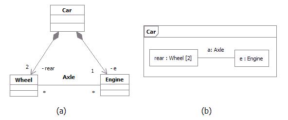
Example: Parts playing their roles inside a structured class
Connector
A connector is an instance of relationship between two parts in a structured class. It is a link to allow communication. Connectors may be implemented by ordinary associations or by transient relationships, such as procedure parameters, variables, global values, or other mechanisms.
The internal “wiring” of a structured class is specified with assembly connectors and delegation connectors:
-
Within the implementation of a structured class, assembly connectors connect ports of different parts. A message sent on a port of one structured class is received on a connected port of another structured class. A set of parts may be wired together through their ports. A part need not know anything about other parts, except that they exist and satisfy the constraints on connected ports. Communication among structured classes is modeled by their ports.
-
A delegation connector connects an external port of a structured class with a port on one of its internal parts. A message received by the external port is passed to the port on the internal part; a message sent by the internal port is passed to the external port and then to the structured class connected to it.
Port
A port is a structural feature of a structured class. Encapsulation can be increased by forcing communications from outside the structured class to pass through ports obeying declared interfaces, which brings additional precision in specification and interconnection for that structured class.
The required and provided interfaces of a port specify everything that is necessary for interactions through that interaction point. If all interactions of a structured class with its environment are achieved through ports, then the internals of the structured class are fully isolated from the environment. This allows such a structured class to be used in any context that satisfies the constraints specified by its ports.
There is no assumption about how a port is implemented. It might be implemented as an explicit object, or it might be merely a virtual concept that does not explicitly appear in the implementation.
Examples of ports are provided below:
Example 1
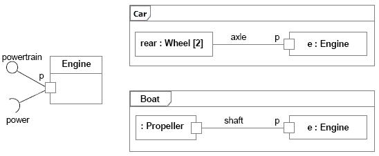
Port of an Engine being used by a Car and a Boat
The figure above shows a class Engine with a port p and two interfaces:
- A provided interface powertrain, which specifies the services that the engineoffers at this port (i.e., the operations and receptions that are accessible by communication arriving at this port).
- A required interface power, which specifies the services that the engine expects its environment to provide.
At port p, the Engine class is completely encapsulated; it can be specified without any knowledge of the environment the engine will be embedded in. As long as the environment obeys the constraints expressed by the provided and required interfaces of the engine, the engine will function properly.
To illustrate that, two uses of the Engine class are shown in this example:
- The Car class connects port p of the engine to a set of wheels by means of the axle.
- The Boat class connects port p of the engine to a propeller by means of the shaft.
As long as the interaction between the Engine and the part linked to its port p obeys the constraints specified by the provided and required interfaces, the engine will function as specified, whether it is an engine of a car or an engine of a boat.
Furthermore, even if Engine had other declared ports, such as a port f for Fuel Consumption, the wheels of a car and the propeller of a boat would still access the Engine through port p. Port f would be of interest of a fuel meter, regardless of what kind of fuel is being used and what kind of fuel meter cars and boats might have.
Example 2
This example of ports is based on Java Logging API ([JAV03]), which is a package that provides the following classes and interfaces of the Java 2 platform’s core logging facilities, among others:
Logger is the main entity on which applications make logging calls. It is used to log messages for a specific system or application component Level gives a guide to the importance and urgency of a log message Filter provides fine grain control of what is logged, beyond the control provided by the log levels Handler takes messages from a Logger and exports them to different destinations (memory, output streams, consoles, files and sockets) Formatter provides support for formatting log records
Those classes and interfaces are involved in two important kinds of collaborations. Some classes and interfaces are used to write to the log while others are used to administrate the log. The figure below shows two different collaborations that clients and administrators have with the log, modeled as UML collaborations:
Writing collaboration, where the LogClient role connects to the LogWriter role in order to write to the log. Administration collaboration, where the LogAdministrator role connects to the LogController role in order to access the log and change log settings.
Different collaborations that clients and administrators have with the log
One possible UML 2.0 representation to model the logging services and its collaborations would be using a component with ports and declared interfaces, as shown in the figure below:
Java Logging API package being implemented as a component with provided interfaces grouped into ports
In the Java Logging API specification, some of the logging services were implemented as classes and others as interfaces. In this example, we model each of those services as provided interfaces, which could be realized by parts inside the component. The two different kinds of behavior related to Writing and Administration collaborations mentioned above could be represented by interfaces logically grouped into ports. Therefore, we have:
Logger and Level interfaces grouped into LogWriter port. Those interfaces are accessed by log clientsto write to the log**.** Handler, Filter and Formatter interfaces grouped into LogController port. Those interfaces are accessed by log administrators to access the log and change log settings.
This modeling alternative brings a separation of concerns, by logically grouping interfaces into different ports. We have additional precision for the component specification and the interconnection it can have with the external world.
Modeling
During design, classes and components may be decomposed into collections of connected parts that may be further decomposed in turn.
A composite structure diagram can be used to show the decomposition of a structured class. As an example, the figure below shows a composite structure diagram for the box office in the ticketing system. This class is decomposed into three parts:
- A ticket seller interface
- A performance guide that retrieves performances according to date and other criteria
- A set of databases that contain the data on the performances and the tickets.
Each part interacts through a well-defined interface specified by its ports. The entire box office interacts with the outside through a port. Messages on this port are dispatched to the ticket seller class, but the internal structure of the box office class is hidden from outside clients.
Example: Composite structure diagram for a ticketing system.
UML 1.x Representation
Note that Structured Class is a new concept in UML 2.0.
Much of what RUP defines as Capsule can be represented using Structured Class as notation (see Artifact: Capsule and Guidelines: Capsule for more information on this topic).
If your tool supports only UML 1.5, an alternative representation is also discussed in Artifact: Capsule and Guidelines: Capsule.
Refer to Differences Between UML 1.x and UML 2.0 for more information.
Concepts: Web Architecture Patterns
Topics
- Introduction
- [Thin Web Client](#Thin Web Client)
- Applicability
- [Known Uses](#Known Uses)
- Structure
- Dynamics
- Consequences
- [Thick Web Client](#Thick Web Client)
- Applicability
- [Known Uses](#Known Uses1)
- Structure
- Dynamics
- Consequences
- [Web Delivery](#Web Delivery)
- Applicability
- [Known Uses](#Known Uses2)
- Structure
- Dynamics
- Consequences
Introduction
The three most common patterns are:
Thin Web Client - Used mostly for Internet based applications, where there is little control of the client’s configuration. The client only requires a standard web browser (forms capable). All of the business logic is executed on the server.
Thick Web Client - An architecturally significant amount of business logic is executed on the client machine. Typically the client utilizes Dynamic HTML, Java Applets, or ActiveX controls to execute business logic. Communication with the server is still done via HTTP.
Web Delivery - In addition to use of the HTTP protocol for client and server communication, other protocols such as IIOP and DCOM may be employed to support a distributed object system. The web browser acts principally as a delivery and container device for a distributed object system.
This list cannot be considered complete, especially in an industry where technological revolutions seem to happen annually. It does represent, at a high level the most common architectural patterns of web applications. As with any pattern it is conceivable to apply several to a single architecture.
Thin Web Client
The Thin Web Client architectural pattern is useful for Internet-based applications, for which only the most minimal client configuration can be guaranteed. All business logic is executed on the server during the fulfillment of page requests for the client browser.
Applicability
This pattern is most appropriate for Internet-based Web applications or for those environments in which the client has minimal computing power or no control over its configuration.
Known Uses
Most e-commerce Internet applications use this pattern, as it doesn’t make good business sense to eliminate any sector of customers just because they do not have sufficient client capabilities. A typical e-commerce application tries to reach the largest customer pool possible; after all, a Commodore Amiga user’s money is just as good as a Windows NT user’s.
Structure
The major components of the Thin Web Client architecture pattern exist on the server. In many ways, this architecture represents the minimal Web application architecture. The major components are as follows:
Client browser-Any standard forms-capable HTML browser. The browser acts as a generalized user interface device. When used in a Thin Web Client architecture, the only other service it provides is the ability to accept and to return cookies. The application user uses the browser to request Web pages: either HTML or server. The returned page contains a fully formatted user interface - text and input controls-which is rendered by the browser on the client display. All user interactions with the system are through the browser.
Web server-The principal access point for all client browsers. Client browsers in the Thin Web Client architecture access the system only through the Web server, which accepts requests for Web pages
- either static HTML or server pages. Depending on the request, the Web server may initiate some server-side processing. If the page request is for a server scripted page, CGI, ISAPI, or NSAPI module, the Web server will delegate the processing to the appropriate script interpreter or executable module. In any case, the result is an HTML-formatted page, suitable for rendering by an HTML browser.
HTTP connection - The most common protocol in use between client browsers and Web servers. This architectural element represents a connectionless type of communication between client and server. Each time the client or the server sends information to the other, a new and separate connection is established between the two. A variation of the HTTP connection is a secure HTTP connection via Secure Sockets Layer (SSL). This type of connection encrypts the information being transmitted between client and server, using public/private encryption key technology.
HTML page -A Web page with user interface and content information that does not go through any server-side processing. Typically these pages contain explanatory text, such as directions or help information, or HTML input forms. When a Web server receives a request for an HTML page, the server simply retrieves the file and sends it without filtering back to the requesting client.
Server page -Web pages that go through some form of server-side processing. Typically, these pages are implemented on the server as scripted pages (Active Server Pages, Java Server Pages, Cold Fusion pages) that get processed by a filter on the application server or by executable modules (ISAPI or NSAPI). These pages potentially have access to all server-side resources, including business logic components, databases, legacy systems, and merchant account systems.
Application server -The primary engine for executing server-side business logic. The application server is responsible for executing the code in the server pages, can be located on the same machine as the Web server, and can even execute in the same process space as the Web server. The application server is logically a separate architectural element, since it is concerned only with the execution of business logic and can use a completely different technology from the Web server.
The figure below shows a diagram of the logical view for the Thin Web Client architecture.
Minimal Thin Web Client Architecture
The minimal Thin Web Client architecture is missing some common optional components that are typically found in web applications; most notably the database. Most web applications use a database to make the business data persistent. In some situations the database may also be used to store the pages themselves (this use of a database however, represents a different architectural pattern). Since web applications can use any number of technologies to make business data persistent, the architectural component is labeled with the more generic term: Persistence. The Persistence component also includes the possible use of a Transaction Processing Monitor (TPM).
The simplest way to connect a database to the system is to allow the scripts in the server pages direct access to the Persistence component. Even this direct access utilizes standard data access libraries like RDO, ADO, ODBC, JDBC, DBLib, etc. to do the dirty work. In this situation the server pages are knowledgeable of the database schema. For relational database systems they construct and execute the necessary SQL statements to gain access to data in the database. In smaller and less complicated web applications this can be sufficient. For larger and more robust systems however the use of a full business object layer is preferred.
A business object component encapsulates the business logic. This component is usually compiled and executed on the application server. One of the advantages of having a business object architectural component is that other web or client server systems can use the same components to invoke the same business logic. For example an Internet based store front may use server pages and the Thin Web Client architectural pattern for all consumer activity however, the billing division may require more sophisticated access to the data and business logic and prefer to use a client server system over a web based one. The billing division’s system can utilize the same business components on the same application server as the web front, yet use their own and more sophisticated client software.
Since relational databases are the most common type of database in mainstream businesses, an additional architectural component is usually present between the application server and the database. It provides a mapping service between objects and relational databases. This mapping layer itself can be implemented in a number of ways. Detailed discussions of this component are beyond the scope of this page.
Other options that are commonly added to this architectural pattern are integration with legacy systems and for e-commerce applications; a merchant account system. Both are accessed via the business objects (or the application server for those systems without a formal business object component). Legacy systems could represent an accounting system or manufacturing scheduling system. The merchant account system enables an Internet web application to accept and process credit card payments. There are many merchant account systems available for small businesses wanting to get into the on-line market. For larger businesses this component would most likely be a interface to an already existing system capable of processing credit card requests.
With these optional components in place the logical view of the Thin Web Client architectural pattern becomes more complete. The logical view is shown in the figure below.
Thin Web Client Logical View
Much of a web application’s server components can be found on non-web based applications as well. The design and architecture of a web application’s back end is not unlike the design of any mainframe or client/server system. Web applications employ the use of databases and transaction processing monitors (TPM) for the same reasons that other systems do. Enterprise Java Beans (EJB) and Microsoft’s Transaction Server (MTS) are new tools and technologies that were introduced with Web applictions in mind but are equally suited for use in other application architectures.
The architecture and design of a web application’s server side components is treated exactly like that of any client server system. Since this architectural pattern focuses on the web and the components specific to web applications, a detailed review of possible back end server architectures is beyond the scope of this pattern.
Dynamics
The underlying principal of the dynamics of this architectural pattern is that business logic only gets executed in response to a web page request by the client. Clients use the system by requesting web pages from the web server with the HTTP protocol. If the requested page is an HTML file on the web server’s file system, it simply fetches it and sends it back to the requesting client.
If the page is a scripted page, that is a page with interpretable code that needs to be processed before it can be returned to the client, then the web server delegates this action to the application server. The application server interprets the scripts in the page, and if directed to, interacts with server side resources like databases, email services, legacy systems, etc. The scripted code has access, through the application and web server, to special information accompanying the page request. This information includes form field values entered by the user, and parameters appended to the page request. The ultimate result is a properly formatted HTML page suitable for sending back to the client.
The page may also be an executable module like an ISAPI or NSAPI DLL. A DLL or dynamic link library is a compiled library that can be loaded and executed at run time by the application server. The module has access to the same details about the page request (form field values and parameters) that scripted pages have.
The key point of the dynamic behavior of this pattern is that business logic is only invoked during the processing of a page request. Once the page request has been fulfilled, the result is sent back to the requesting client, and the connection between the client and server is terminated. It is possible for a business process to linger on after the request is fulfilled, but this is not the norm.
Consequences
This type of architecture is best suited to applications whose server response can be completed within the acceptable response time expected by the user (and within the timeout value allowed by the client browser). This is usually on the order of no more than a few seconds. This may not be the most appropriate architecture pattern if the application needs to allow the user to start and monitor a business process that lasts a long time. The use of push technologies however can be employed to allow the client to monitor long running processes. For the most part push technologies just employ periodic polling of the server.
Another major consequence of this architectural pattern is the limited ability for sophisticated user interfaces. Since the browser acts as the entire user interface delivery mechanism, all user interface widgets and controls must be available via the browser. In the most common browsers, and in the HTML specifications these are limited to a few text entry fields and buttons. On the other hand, it could be argued that such a severely limited user interface is a plus. Sparse user interface offerings prevent the development team from spending effort on “cool” and “neat” interfaces, when more simpler ones would suffice.
Thick Web Client
The Thick Web Client architectural pattern extends the Thin Web Client pattern with the use of client side scripting and custom objects like ActiveX controls and Java Applets. The Thick Web Client pattern gets its name from the fact that the client can actually execute some of the business logic of the system and hence becomes more than just a generalized user interface container.
Applicability
The Thick Web Client architectural pattern is most appropriate for web applications where a certain client configuration and browser version can be assumed, a sophisticated user interface is desired, and/or a certain amount of the business logic can be executed on the client. Much of the distinction between the Thin Web Client and Thick Web Client patterns is in the role the browser plays in the execution of the system’s business logic.
The two strong motivations for Thick Web Client usage are enhanced user interface capability and client execution of business logic. A sophisticated user interface could be used to view and modify three dimensional models, or animate a financial graph. In some instances the ActiveX control can be used to communicate with client side monitoring equipment. For example health care equipment that can measure blood pressure, sugar count, and other vital signs could be used by an agency that needs to monitor geographically remote patients on a daily basis, and be able to cut down on personal visits to twice a week.
In some situations business logic can be executed on the client alone. In these situations all the data required to carry out the process should be available on the client. The logic may be as simple as validating entered data. Dates can be checked for accuracy, or compared with other dates (for example the birth date should be before the date first admitted to the hospital). Depending upon the business rules of the system some fields may or may not be enabled depending upon the currently entered values.
Known Uses
The most obvious uses of client side scripts, applets, controls and plug-ins is on the Internet in the form of enhanced user interfaces. Java Scripts are often used to change the color or image of a button or menu item in HTML pages. Java Applets and ActiveX controls are often used to create sophisticated hierarchical tree view controls.
The Shockwave ActiveX control and plug-in is one of the most common user interface components in use on the Internet today. It enables interactive animations, and is primarily used to spice up Internet sites with attractive graphics, but is also being used to display simulations, and monitor sporting events.
Microsoft’s agent control is used by several Internet sites to accept voice commands and execute actions in the browser that assist the user navigating the web site.
Off of the Internet, a healthcare software company has developed a web based intranet application to manage patient records and billing. The web based user interface make heavy use of client side scripting to perform data validations and assist the user in navigation of the site. In addition to scripts, the application uses several ActiveX controls to manage XML content, which is used as the primary encoding scheme for information.
Structure
All communication between client and server, like in the Thin Web Client pattern, is done with HTTP. Since HTTP is a “connectionless” type of protocol, most of the time there is no open connection between client and server. Only during page requests does the client send information. This means that client side scripting, ActiveX controls and Java Applets are limited to interacting with objects only on the client.
The Thick Web Client pattern utilizes certain browser capabilities like ActiveX controls or Java Applets to execute business logic on the client. ActiveX controls are compiled, binary executables that can be downloaded to the client via HTTP, and invoked by the browser. Since they are ActiveX controls are essentially COM objects, they have full reign over client side resources. They can interact with both the browser as well as the client system itself. For this reason ActiveX controls, especially those on the Internet, are typically “authenticated” by a third trusted party
The most recent versions of common HTML browsers also allow client side scripting. HTML pages can be embedded with scripts written in Java Script or VB Script. This scripting capability enables the browser itself to execute (or rather interpret) code that may be part of the business logic of the system. The term “maybe” is used since it is very common for client scripts to contribute only to extraneous aspects of the user interface, and not actually be part of the business logic. In either case, there are potentially architecturally significant elements (i.e. scripts) embedded inside HTML pages that need to be expressed as such.
Since the Thick Web Client pattern is really just an extension to the Thin Web Client pattern, most of the architecturally significant elements are the same. The additional elements that the Thick Web Client pattern introduces are:
Client Script - JavaScript or Microsoft® VirtualBasic® script embedded in HTML formatted pages. The browser interprets the script. The W3C (an Internet standards body) has defined the HTML and Document Object Model interface that the browser offers to client scripts.
XML Document - A document formatted with the eXtensible Markup Language (XML). XML Documents represent content (data) without user interface formatting.
ActiveX Control - A COM object that can be referenced in a client script and “downloaded” to the client if necessary. Like any COM object, it has full access to client resources. The principle security mechanism for protecting client machines is through authentication and signing. Internet browsers can be configured to not accept, or warn the user when ActiveX controls are about to be downloaded to the client. The authentication and signing mechanisms merely establish the identity of the author of the control through a trusted third party.
Java Applet - A self contained and compiled component that runs in the context of a browser. For security reasons it has limited access to client side resources. Java Applets are used both as sophisticated user interface elements, and for non-user interface purposes such as parsing XML documents, or to encapsulate complicated business logic.
Java Bean - A Java component that implements a certain set of interfaces that enable it to be easily incorporated into larger more complex systems. The term bean reflects the small nature and single purpose the component should have. A full cup of coffee usually takes more than one bean. ActiveX is the analog to the Java Bean in Microsoft centered architectures.
The figure below shows a diagram of the Logical View for the Thick Web Client Architecture.
Logical View of the Thick Web Client Architecture Pattern
Dynamics
The principal dynamics of the Thick Web Client pattern include those of the Thin Web Client pattern plus the ability to execute business logic on the client. As with the Thin Web Client pattern, all communication between the client and server is done during page requests. The business logic however, can be partially executed on the client with scripts, controls or applets.
When a page is sent to a client browser it may contain scripts, controls and applets. They may be used simply to enhance the user interface, or contribute to the business logic. The simplest business logic uses are field validations. Client scripts can be used to check for valid input, not only in a single field, but across all fields in any given web page. For example an e-commerce application that allows users to configure their own computer systems may use scripts to prevent incompatible options from being specified.
In order for Java Applets and ActiveX controls to be used, they must be specified in the content of the HTML page. These controls and applets can work independently of any scripts in the page or be driven by scripts in the page. Scripts in an HTML page can respond to special events sent by the browser. These events can indicate that the browser has just completed loading the web page, or that the user’s mouse just moved over a specific region of the page.
They have access to the browser’s Document Object Model (DOM) interface. This interface is a W3C standard for giving scripts, controls and applets access to the browser and HTML content in pages. Microsoft’s and Netscape’s implementation of this model is Dynamic HTML (DHTML). DHTML is more than just an implementation of the DOM interface, it particular DHTML includes events, which at the time of this writing are not part of the DOM Level 1 specification.
At the core of the Document Object Model is a set of interfaces that specifically handle XML documents. XML is a flexible language that enables designers to create their own special purpose tags. The DOM interface enables client scripts to access XML documents
The use of XML as a standard mechanism of exchanging information between client and server is enabled by the use of special components on the client. ActiveX controls or Java Applets can be placed on the client to independently request and send XML documents. For example a Java Applet embedded in an HTML page could make an HTTP request from the web server for an XML document. The web server finds and processes the requested information and sends back not an HTML document, but an XML formatted one. The Applet still running in the HTML page on the client would accept the XML document, parse it and interact with current HTML document in the browser to display its content for the user. The entire sequence happens in the context of a single HTML page in the client browser.
Consequences
By far the biggest consequence of this pattern is portability across browser implementations. Not all HTML browsers support Java Script or VirtualBasic Script. Additionally only Microsoft Windows based clients can use ActiveX controls. Even when a specific brand of client browser is exclusively used there are subtle differences in implementations of the Document Object Model.
When client scripting, controls or applets are used the testing team needs to perform the full set of test scenarios for each client configuration to be supported. Since critical business logic is being performed on the client it is important that it behaves consistently and correctly for all browsers involved. Never assume that all browsers behave the same. Not only is it possible for different browsers to behave differently with the same source code, but even the same browser running on different operating systems might show anomalous behavior.
Web Delivery
The Web Delivery architectural pattern is named so because the Web is primarily used as a delivery mechanism for an otherwise traditional distributed object client/server system. From one viewpoint this type of application is really a distributed object client/server application that just happens to include a web server and client browser as significant architectural elements. Whether such a system is a web application with distributed objects or a distributed object system with web elements the ultimate system is the same. The fact that these two viewpoints are of the same system, and distributed object systems have always been seen as systems requiring careful modeling, it further emphasizes the theme in this page that web applications, need to be modeled and designed like any other software system.
Applicability
The Web Delivery architectural pattern is most appropriate when there is significant control over client and network configurations. This pattern is not particularly suited for Internet based applications, where there is no or little control over client configurations, or when network communications are not reliable.
The greatest strengths of this architecture is its ability to leverage existing business objects in the context of a web application. With direct and persistent communications possible between client and server the limitations of the previous two web application patterns can be overcome. The client can be leveraged to perform significant business logic to an even greater degree.
It is unlikely that this architectural pattern is used in isolation. More realistically this pattern would be combined with one or both of the previous patterns. The typical system would utilize one or both of the first architectural patterns for those parts of the system not requiring a sophisticated user interface, or where client configurations are not strong enough to support a large client application.
Known Uses
The CNN Interactive web site is one of the busiest news sites on the Net. Most of its public access is done with conventional browsers and straight HTML 3.2, however behind the web site is a sophisticated CORBA based network of browsers, servers, and distributed objects. A case study of this system was published Distributed Computing.
A healthcare software company has created a web application to manage patients, health records, and billing. The billing aspects of the system are only used by a significantly small proportion of overall user community. Much of the legacy billing systems were written in FoxPro. The new web based system leveraged the old FoxPro legacy code and through the use of some conversion utilities built ActiveX documents for the user interface and business logic. The resulting system is a Thick Web Client based web application for patient and health records, integrated with a Web Delivery based web application for billing operations.
Structure
The most significant difference between the Web Delivery and the other web application architecture patterns is the method of communication between the client and server. In the other patterns the primary mechanism was HTTP, a connectionless protocol that severely limits the designer when it comes to interactive activity between the user and the server. The architecturally significant elements in the Web Delivery pattern include all those specified in Thin Web Client pattern plus these additional ones:
DCOM - Distributed COM is Microsoft’s distributed object protocol. It enables objects on one machine to interact with and invoke methods on objects on another machine.
IIOP - Internet Inter-Orb Protocol is OMG’s CORBA protocol for interacting with distributed objects across the Internet (or any TCP/IP based network).
RMI (JRMP) - Remote Method Invocation is the Java way of interacting with objects on other machines. JRMP (Java Remote Method Protocol) is the native protocol for RMI, but not necessarily the only protocol that can be used. RMI can be implemented with CORBA’s IIOP.
The figure below shows a diagram of the Logical View for the Web Delivery Architecture pattern.
Logical View of the Web Delivery Architecture Pattern
Dynamics
The principal dynamics of the Web Delivery architectural pattern are the use of the browser to deliver a distributed object system. The browser is used to contain a user interface and some business objects that communicate, independently of the browser to objects in the server tier. Communications between client and server objects occur with IIOP, RMI and DCOM protocols.
The main advantage of using a web browser in this otherwise distributed object client server system is that the browser has some built in capabilities to automatically download the needed components from the server. A brand new computer to the network needs only a compatible web browser to begin using the application. Special software does not need to be manually installed on the client, since the browser will manage this for the user. Components are delivered and installed on the client on a as-needed basis. Both Java Applets and ActiveX controls can be automatically sent to and cached on the client. When these components are activated (as a result of loading the appropriate web page) they can engage in asynchronous communication with server objects.
Consequences
By far the biggest consequence of this pattern is portability across browser implementations. The use of this pattern requires a solid network. Connections between client and server objects last much longer than HTTP connections, and so sporadic loss of server, which is not a problem with the other two architectures poses a serious problem to be handled in this pattern.
Guideline: Representing Graphical User-Interfaces
In systems in which there is a great deal of user interaction, it is often desirable to represent the entire user interface as a single analysis class during Use-Case Analysis. These classes are, in reality, composed of many different kinds of other classes: buttons, windows, menus, sub-panes, controls, etc. Using a single class to represent this complex collaboration is sometimes too great an over-simplification. While a single class could be used, refining it as we go along, it is often easier to represent this with a more encompassing concept, the subsystem.
In this case, a single class (or subsystem) was used to represent complex collaborations such as GUI interfaces due to our limited design vocabulary. This class was regarded, in a sense, as the entry point to complex collaborations, but it really was not a class in the real sense (it did not have a single well-defined set of responsibilities, except in a very loose sense) and it often disappeared in the design process. In the end, one discovers the real classes and collaborations, and distributes the behavior of each place-holder class to them. Some of the work performed in Prototype the User Interface by the Role: User-Interface Designer when producing the Artifact: User-Interface Prototype may be able to be carried forward and reused, depending on the nature of that prototype.
Guideline : Representing Interfaces to External Systems
If the system communicates with another system, there will be one or more boundary classes identified in Activity: Use Case Analysis to describe the communication protocol. Another system may be anything from software to hardware units that the current system will use, such as printers, terminals, alarm devices, and sensors. In each case, a boundary class will be identified whose purpose is to mediate the communication with the other system.
Example
An Automated Teller Machine (ATM) must communicate with the ATM Network to ascertain whether a customer’s bank number and PIN are correct, and whether they have sufficient funds in their account to effect a withdrawal. Since the ATM Network is an external system (from the perspective of the ATM), we would use a boundary class to represent it in Use Case Analysis.
If the interface(s) to the system are simple and well-defined, a single class may be sufficient to represent the external system. Often, however, these interfaces are too complex to be represented using a single class; they often require complex collaborations of many classes. Moreover, interfaces between systems are often highly reusable across applications. As a result, in many cases, a subsystem more appropriately models the system interfaces.
The use of a subsystem allows the interface to the external system to be defined and stabilized, while leaving the design details of the system interface to remain hidden while its definition evolves.
Analysis & Design: Activity Overview
Analysis & Design: Workflow
In the Inception Phase, analysis and design is concerned with establishing whether the system as envisioned is feasible, and with assessing potential technologies for the solution (in Perform Architectural Synthesis). If it is felt that little risk attaches to the development (because, for example, the domain is well understood, the system is not novel, and so on) then this workflow detail may be omitted.
The early Elaboration Phase focuses on creating an initial architecture for the system (Define a Candidate Architecture) to provide a starting point for the main analysis work. If the architecture already exists (either because it was produced in previous iterations, in previous projects, or is obtained from an application framework), the focus of the work changes to refining the architecture (Refine the Architecture) and analyzing behavior and creating an initial set of elements which provide the appropriate behavior (Analyze Behavior).
After the initial elements are identified, they are further refined. Design Components produce a set of components which provide the appropriate behavior to satisfy the requirements on the system. If the system includes a database, then Design the Database occurs in parallel. The result is an initial set of components which are further refined in Implementation.
Workflow Detail: Analyze Behavior
| The purpose of this Workflow Detail is to transform the behavioral descriptions provided by the requirements into a set of elements upon which the design can be based. | |
| Topics - Description - Related Information - Timing - Optionality - How to Staff - Work Guidelines |
Description
This Workflow Detail occurs in each iteration in which there are behavioural requirements to be analyzed and designed.
The analysis of behavioural requirements includes:
- identifying analysis classes that satisfy the required behaviour
- determining how these analysis classes fit into the logical architecture (the major subsystems and classes) of the system. The analysis classes may be determined to belong to existing subsystems, require the creation of new subsystems, or cause existing subsystems and their interfaces to be redefined.
This Workflow Detail may also include modeling and prototyping of the user interface.
Related Information
This section provides links to additional information related to this workflow detail.
Timing
Starts in Elaboration phase, recurs through Construction and Transition phases.
Optionality
Required
How to Staff
Especially in larger projects, user-interface design and prototyping is performed by a separate group of people, focused only on usability of the system and the user interface. However, this group should work closely with other members of the development team, especially those responsible for the requirements and the business logic, to make sure that the user interface is what the user expects, and that the business logic provides what the user interface requires (in terms of content and user actions).
The Activity: Use-Case Analysis is best conducted by a small group with a blend of skills; staffing guidelines are presented in Guidelines: Use-Case Analysis Workshop. The Activity: Identify Design Elements requires a broader perspective of the architecture and the results of other use-case analysis workshops, and requires some experience in the implementation technology and any frameworks being used on the project. Reviews should be staffed with people who have both in-depth knowledge of the implementation technologies as well as an understanding of the problem domain.
Work Guidelines
Activity: Design the User-Interface and Activity: Prototype the User-Interface are performed iteratively throughout the Elaboration iterations. Early iterations focus on the initial user interface design, which includes the identification and design of the key user interface elements and the navigation paths between them. Storyboarding is an effective technique that can be used during user-interface design to gain a better understanding of how the user interface should behave. Once consensus on the initial user-interface design has been reached, then the development of an executable user-interface prototype begins. Feedback on the prototype is fed back into the user-interface design (and possibly even the requirements). The initial prototype typically supports only a subset of the system’s features. In subsequent iterations, the prototype is expanded, gradually adding broader coverage of the system’s features. The main benefit of producing non-functional versions of the user-interface during user-interface design is to postpone the investment of more elaborate and costly functional user-interface prototypes until there is consensus on the overall user-interface design. It is important to work closely with users and potential users of the system when designing and prototyping the user-interface in order to confirm and validate the usability of the system.
A number of use-case analysis workshops may be organized in parallel, limited only by the available resource pool and the skills of the participants. As soon as possible following each use-case analysis workshop, some members of the workshop and some members of the architecture team should work to merge the results of the workshop in the Activity: Identify Design Elements. Members of both teams are essential: the use-case analysis team members understand the context in which the analysis classes were identified, while the architecture team understands the greater context of the design as well as other use cases which have already been identified.
As the design work matures and stabilizes, increasingly larger parts of it can and should be reviewed. Smaller, more focused reviews are better than large all-encompassing reviews; sixteen two-hour reviews focused on very specific aspects are significantly better than a single review spanning two days. In the focused reviews, define objectives to bound the focus of the review, and ensure that a small review team with the right skills for the review, given the objectives, is available for the review. Early reviews should focus primarily on the integrity of layering and packaging in the design, the stability and quality of the interfaces, and the completeness of coverage of the use case behavior. Later reviews should drill down into packages and subsystems to ensure that their contents completely and correctly realize their defined interfaces, and that the dependencies and associations between design elements are necessary, sufficient and correct. See the check-points on each design artifacts for specific review points.
Workflow Detail: Define a Candidate Architecture
| The purpose of this workflow detail is to create an initial sketch of the software architecture. | |
| Topics - Description - Related Information - Timing - Optionality - How to Staff - Work Guidelines |
Description
This workflow detail has the following goals:
- Create an initial sketch of the architectureof the system
- Define an initial set of architecturally significant elementsto be used as the basis for analysis
- Define an initial set of analysis mechanisms
- Define the initial layering and organizationof the system
- Define the use-case realizations to be addressed in the current iteration
- Identify analysis classesfrom the architecturally significant use cases
- Update the use-case realizations with analysis class interactions
Related Information
This section provides links to additional information related to this workflow detail.
Timing
Early part of Elaboration phase.
Optionality
Required
How to Staff
These activities are best carried out by a small team staffed by cross-functional team members. Issues that are typically architecturally significant include performance, scaling, process and thread synchronization, and distribution. The team should also include members with domain experience who can identify key abstractions. The team should also have experience with model organization and layering. The team will need to be able to pull all these disparate threads into a cohesive, coherent (albeit preliminary) architecture.
Work Guidelines
The work is best done in several sessions, perhaps performed over a few days (or weeks and months for very large systems), with iteration between Architectural Analysis and Use-Case Analysis. Perform an initial pass at the architecture in Architectural Analysis, then choose architecturally significant use cases, performing Use-Case Analysis on each one. After (or as) each use case is analyzed, update the architecture as needed to reflect adaptations required to accommodate new behavior of the system and to address potential architectural problems which are identified.
Where the architecture already exists (either from a prior project or iteration), change requests may need to be created to change the architecture to account for the new behavior the system must support. These changes may be to any artifact in the process, depending on the scope of the change.
Workflow Detail: Design Components
| The purpose of this workflow detail is to refine the design of the system. | |
| Topics - Description - Related Information - Timing - Optionality - How to Staff - Work Guidelines |
Description
This Workflow Detail has the following goals:
- Refine the definitions of design elements (including capsules and protocols) by working out the ‘details’ of how the design elements realize the behavior required of them.
- Refine and update the use-case realizations based on new design element identified (i.e. keeping the use-case realizations updated)
- Reviewing the design as it evolves
Related Information
This section provides links to additional information related to this workflow detail.
Timing
Starts in Elaboration phase. Recurs through Construction and Transition phases.
Optionality
Required
How to Staff
Typically, one person or a small team is responsible for a set of design elements, usually one or more packages or subsystems containing other design elements. This person/team is responsible for fleshing out the design details for the elements contained in the package or subsystem: completing all operation definitions and the definition of relationships to other design elements. The Activity: Capsule Design focuses on the recursive decomposition of functionality in the system in terms of capsules and (passive or data) classes. The Activity: Class Design focuses on refining the design of passive class design elements, while the Activity: Subsystem Design focuses on the allocation of behavior mapped to the subsystem itself to contained design elements (either contained capsules and classes or subsystems). Typically subsystems are used primarily as large-grained model organization structures, while capsules being used for the bulk of the work and “ordinary” classes being relegated largely to passive stores of information.
The individuals or teams responsible for designing capsules should be knowledgeable in the implementation language as well as possessing expertise in the concurrency issues in general. Individuals responsible for designing passive classes should also be knowledgeable in the implementation language as well as in algorithms or technologies to be employed by the class. Individuals or teams responsible for subsystems should be more generalists, able to make decisions on the proper partitioning of functionality between design elements, and able to understand the inherent trade-offs involved in various design alternatives.
While the individual design elements are refined, the use-case realizations must be refined to reflect the evolving responsibilities of the design elements. Typically, one person or a small team is responsible for refining one or more related use-case realizations. As design elements are added or refined, the use-case realizations need to be reconsidered and evolved as they become outdated, or as improvements in the design model allow for simplifications in the use-case realizations. The individuals or teams responsible for use-case realizations need to have broader understanding of the behavior required by the use cases and of the trade-offs of different approaches to allocating this behavior amongst design elements. In addition, since they are responsible for selecting the elements that will perform the use cases, they need to have a deep understanding of external (public) behaviors of the design elements themselves.
Work Guidelines
Typically the work here is carried in individually or in small teams, with informal inter-group interactions where needed to communicate changes between the teams. As design elements are refined, responsibilities often shift between them, requiring simultaneous changes to a number of design elements and use-case realizations. Because of the interplay of responsibilities, it is almost impossible for design team members to work in complete isolation. To keep the design effort focused on the required behavior of the system (as expressed in use-case realizations), a typical pattern of interaction emerges:
- design elements are refined by the responsible persons or teams
- a small group (perhaps 2-5 people) gathers informally to work out the impact of the new design elements on a set of existing use-case realizations
- in the course of the discussion, changes to both the use-case realization and the participating design elements are identified
- the cycle repeats until all required behaviour for the iteration is designed.
Because the process itself is iterative, the criteria for ‘all required behaviour for the iteration’ will vary depending on the position in the lifecycle:
- In the elaboration phase, the focus will be on architecturally-significant behaviors, with all other ‘details’ effectively ignored (or more likely ‘stubbed-out’)
- In the construction phase there is a shift to completeness and consistency of the design, so that by the end of the construction phase there are no unresolved design issues.
Note that the design for an iteration does not need to be complete before beginning implementation and test activities. Partially implementing and testing a design as it evolves can be an effective means of validating and refining design, even within an iteration.
Workflow Detail: Design the Database
| The purpose of this workflow detail is to identify the design classes to be persisted in a database, and design the corresponding database structures. | |
| Topics - Description - Related Information - Timing - Optionality - How to Staff - Work Guidelines |
Description
This Workflow Detail includes:
- Identifying the persistent classes in the design
- Designing appropriate database structures to store the persistent classes
- Defining mechanisms and strategies for storing and retrieving persistent data in such a way that the performance criteria for the system are met
The database and persistent data storage and retrieval mechanisms, are implemented and tested as part of the overall implementation of the components and subsystems of the application.
Related Information
This section provides links to additional information related to this workflow detail.
Timing
Starts in Elaboration phase, recurs through Construction and Transition phases.
Optionality
Optional (required if the system includes a database)
How to Staff
The Designers responsible for persistent classes need to have an understanding of the persistence in general and the persistence mechanisms in specific. Their primary responsibility is to ensure that persistent classes are identified and that these classes utilize the persistence mechanisms in an appropriate manner. The Database Designer needs to understand the persistent classes in the design model and so must have a working understanding of object-oriented design and implementation techniques. The Database Designer also needs a strong background in database concurrency and distribution issues.
Work Guidelines
In the elaboration phase, this workflow focuses on ensuring that the persistence strategy is scalable and that the database design and persistence mechanism will support the throughput requirements of the system. Persistent classes identified in Activity: Class Design are mapped to the persistence mechanism and data-intensive use cases are analyzed to ensure the mechanisms will be scalable. The persistence mechanism and database design is assessed and validated.
Persistence must be treated as an integral part of the design effort, and close collaboration between designers and database designers is essential. Typically the database designer is a ‘floating’ resource, shared between several teams as a consulting resource to address persistence issues. The database designer is also typically responsible for the persistence mechanisms; if the persistence mechanism is built rather than bought, there will typically be a team of people working on this. Larger projects will typically require a small team of database designers who will need to coordinate work between both design teams and amongst themselves to ensure that persistence is consistently implemented across the project.
Workflow Detail: Perform Architectural Synthesis
| The purpose of this workflow detail is to construct and assess an Architectural Proof-of-Concept to demonstrate that the system, as envisioned, is feasible. | |
| Topics - Description - Related Information - Timing - Optionality - How to Staff - Work Guidelines |
Description
This workflow detail is about showing that there exists, or is likely to exist, a solution which will satisfy the architecturally significant requirements, thus showing that the system, as envisioned, is feasible.
Related Information
This section provides links to additional information related to this workflow detail.
Timing
Inception phase
Optionality
Optional
How to Staff
As with Workflow Detail: Define a Candidate Architecture, these activities are best carried out by a small team staffed by cross-functional team members. Issues that are typically architecturally significant include performance, scaling, process and thread synchronization, and distribution. The team should also include members with domain experience who can identify key abstractions. The team should also have experience with model organization and layering. From these inputs, the team will need to be able to synthesize a model, or even a prototype, of a solution.
Work Guidelines
This work takes place during inception, and so should be limited to one or two iterations. The purpose is to determine feasibility, not to construct the system during this workflow detail.
Workflow Detail: Refine the Architecture
| The purpose of this workflow detail is to complete the architecture for an iteration. | |
| Topics - Description - Related Information - Timing - Optionality - How to Staff - Work Guidelines |
Description
This Workflow Detail:
- Provides the natural transition from analysis activities to design
activities, identifying:
- appropriate design elements from analysis elements
- appropriate design mechanisms from related analysis mechanisms
- Describes the organization of the system’s run-time and deployment architecture
- Organizes the implementation model so as to make the transition between design and implementation seamless
- Maintains the consistency and integrity of the architecture, ensuring
that:
- new design elements identified for the current iteration are integrated with pre-existing design elements.
- maximal re-use of available components and design elements is achieved as early as possible in the design effort.
Related Information
This section provides links to additional information related to this workflow detail.
Timing
Starts in Elaboration phase, recurs through Construction and Transition phases.
Optionality
Required.
How to Staff
These activities are best carried out by a small teamstaffed by cross-functional team members. Issues that are typically architecturally significant include usability, performance, scaling, process and thread synchronization, and distribution. The team should also include members with domain experience who can identify key abstractions. The team should also have experience with model organization and layering. The team will need to be able to pull all these disparate threads into a cohesive, coherent (albeit preliminary) architecture.
Because the focus of the architecture effort is shifting toward implementation issues, greater attention needs to be paid to specific technology issues. This will force the architecture team to shift members or expand to include people with distribution and deployment expertise (if those issues are architecturally significant). In order to understand the potential impact of the structure on the implementation model on the ease of integration, expertise in the software build management process is useful to have.
At the same time, it is essential that the architecture team not be composed of a large extended team. A strategy for countering this trend is to retain a relatively small core team with a satellite group of extended team members that are brought in as “consultants” on key issues**.** This structure also works well for smaller projects where specific expertise may be borrowed or contracted from other organizations; they can be brought in as specific issues need to be addressed.
Work Guidelines
The work is best done in several sessions, perhaps performed over a few days (or weeks and months for very large systems). The initial focus will be on the activities Identify Design Mechanisms and Identify Design Elements, with a great deal of iteration with the Incorporate Existing Design Elements activity to make sure that new elements do not duplicate functionality of existing elements.
As the design emerges, concurrency and distribution issues are introduced in the activities Describe the Run-time Architecture and Describe Distribution, respectively. As these issues are considered, changes to design elements may be required to split behavior across processes, threads or nodes.
As the individual models are refined to incorporate the architectural decisions, the results are documented in respective view sections in the Software Architecture Document (e.g., as the Design Model is refined, the Logical View of the Software Architecture Document is refined, as well). The resulting architecture is reviewed.
Analysis & Design: Artifact Overview
The roles involved and the artifacts produced in the Analysis & Design discipline.
Analysis & Design: Guidelines
Business Modeling(业务建模): Overview
| This content developed or partially developed by http://www.empulsys.com/rupbm – This hyperlink in not present in this generated websiteEmpulsys BV. |
Introduction to Business Modeling(业务建模)
- Purpose
- Artifacts
- [Process and Notation](#Process and Notation)
- [Relation to Other Disciplines](#Relation to Other Disciplines)
Purpose
The purposes of business modeling are:
- To understand current problems in the target organization and identify improvement potentials.
- To assess the impact of organizational change.
- To ensure that customers, end users, developers, and other parties have a common understanding of the organization.
- To derive the software system requirements needed to support the target organization.
- To understand how a to-be-deployed software system fits into the organization.
An organizational chart is not enough to understand how a business works. We also need a dynamic view of the business. A business model provides a static view of the structure of the organization and a dynamic view of the processes within the organization.
A business needs to change according to the factors that drive it and keep it healthy. These factors might be goals such as reducing costs, improving quality, or shortening time-to-market. We need to model the business to localize problems or identify opportunities for improvements. A characteristic of a healthy-and-learning organization is that it is able to adapt as its business drivers change.
Many different people (stakeholders) need to understand the business. Because all of these people have different backgrounds and interests, they have different views of the business. We need to model the business in a simple, understandable way, using a common notation. The business model must support the ability to be described in different ways using different views and levels of abstraction. If everybody cannot understand your business model, you are missing the point of modeling the business!
Business is about delivering value to customers to make a profit. Running a business is about making decisions, and information is the most important determinant in the quality of decisions [MARS00]. Information systems must be designed to ensure that the information provided is timely, accurate, sufficient, and relevant. We can ensure that information systems support business decisions in this way only if we understand the context in which those decisions are made.
Artifacts
To achieve these goals, the business-modeling discipline describes how to assess the current organization and develop a vision of the new organization. Using this vision as a basis, it then defines the processes, roles, and responsibilities of that organization in a business use-case model and a business-analysis model.
Complementary to these models, the following artifacts are developed:
- Business Vision(愿景)
- Business Architecture(架构) Document
- Supplementary Business Specification
- Business Rules (either as a document and/or as elements in the Business Analysis Model)
- Business Glossary(术语表)
Process and Notation
There are many available business-modeling techniques and notations that have been used with varying degrees of success. However, there are fewer business-modeling processes. The RUP(统一软件开发过程) provides a process for business modeling. The Unified Modeling Language (UML) can be effectively applied to modeling both software and a business. The single most important advantage in using the same modeling notation for both business and software modeling, is that business analysts and software developers share a common language. This allows a direct and efficient translation between models of the business and models of the software systems that support that business.
Modeling, understanding, and improving a business is very much like building a software system. There is a journey of discovery in the beginning that includes defining the objectives and scope. This journey also involves making a broad high-level outline and filling it in piece by piece. We cannot focus on one piece, finish it, and never look at it again. Very often we must revisit pieces that we already have modeled and change them based on new insights and understanding. We cannot wait until we have completely finished modeling the entire business before we start verifying our work and making improvements.
Business modeling is therefore best done in an iterative fashion, starting with the broad overview and filling it in piece by piece. In every iteration, we revisit the broad overview and make any necessary adjustments. We then fill out more of the overview and verify the work that we have done. These steps must be completed before starting the next iteration.
Relation to Other Disciplines
The business-modeling discipline is related to other disciplines, as follows:
- The Requirements(需求) discipline uses business models as an important input to understanding the requirements of the system.
- The Analysis and Design discipline uses business models as an input to defining software systems that seamlessly fit into the organization.
- The Deployment(部署) discipline uses business models as an aid in planning the deployment of a software system.
- The **Environment(环境)**discipline develops and maintains supporting artifacts, such as the Business Modeling Guidelines.
| This content developed or partially developed by http://www.empulsys.com/rupbm – This hyperlink in not present in this generated websiteEmpulsys BV. |
Business Modeling(业务建模): Concepts
Concepts: Activity-Based Costing
Topics
- Introduction
- [Calculating the performance of a business process](#Calculating the Performance of a Business Process)
- [Identifying areas of improvement](#Identifying Areas of Improvement)
Introduction
Activity-based costing (ABC) is a methodology that measures the cost and performance of activities, resources, and cost objects. Resources are assigned to activities, then activities are assigned to cost objects based on their use. Activity-based costing recognizes the causal relationships of cost drivers to activities [PLR99].
Activity-based costing is about:
- Measuring business process performance, activity by activity.
- Estimating the cost of business process outputs based on the cost of the resources used in producing the product.
- Identifying opportunities to improve process efficiency and effectiveness. Activity costs are used as the quantitative measurement. If activities have unusually high costs or it they don’t add value, they become targets for re-engineering.
Activity-based management (ABM) is a broad discipline that focuses on achieving customer value and company profit by managing activities. ABM draws on activity-based costing as a major source of information.
Calculating the Performance of a Business Process
To calculate the performance of a business process, you need to know what the workflow is and what type of resources are involved in performing the workflow. You need to have the following elements describing the workflow in place before you can start measuring:
- A description of the business use case representing the business process-see Guidelines: Business Use Case, and the sections on workflow.
- One or more activity diagrams describing the workflow-see Guidelines: Activity Diagram in the Business Use-Case Model.
- The realization of that business use case-see Guidelines: Business Use-Case Realization.
Basic Cost Drivers
For each activity state in an activity diagram, the basic cost drivers are:
- Resources: determine what business workers and business entities are participating, and how many instances of each. The allocation of a resource to a workflow implies a certain cost.
- Cost rate: each business worker or business entity instance may have a cost per time in use.
- Duration: an activity occurs for a certain time, therefore a resource can either be allocated for the duration of the activity, or for a fixed amount of time.
- Overhead: any fixed costs that the invocation of a workflow or an activity would incur.
Additionally, for a transition you may need to determine the Guard Probability, which is the probability for a transition to be traversed. This needs to be determined for alternative threads such as outgoing transitions from a decision, and for conditional threads such as a conditional transition outgoing from a synchronization bar.
Calculating the Cost of Performing a Workflow
A workflow is described with a collection of activity states. For each of those activity states, you must define what the cost drivers are, in order to calculate the total cost for performing the activity.
Example:
The total cost of performing this activity is ‘number of resources’ * ‘resource cost’ * ’ duration’ + ‘overhead cost’. Knowing that the cost rate for using a customer representative is 200 per hour, the total cost for this activity is then 1*200*0.5 + 100=200.
The total cost of performing the workflow is the sum of the cost for each activity, although there is often an overhead associated with initiating the workflow. For the whole workflow, it may be interesting to calculate the total duration or frequency.
Example:
The workflow depicted in this activity graph has an overhead cost that needs to be added to the cost of performing each activity.
Concurrent Threads
If concurrent threads exist in an activity diagram, the duration of the longest thread is the relevant duration for all threads. Concurrent threads are shown using synchronization bars.
Example:
The total duration for these two concurrent threads is 8 minutes, which is the duration of the longest thread in this case.
Alternative Threads
If alternative threads exist in an activity diagram, the cost for the alternative threads are calculated as the sum of the cost for each alternative, weighted with the occurrence probability for each alternative. Alternative threads are shown using decision icons.
Example:
The total calculated cost for a thread with alternatives is the weighted cost of the alternative threads.
Conditional Threads
If a conditional thread exists, the cost for that thread is added to the cost for its parallel threads, weighted with the probability of it occurring. A conditional thread is indicated with a guard condition on a transition.
Example:
If there is a conditional thread, its cost is first weighted with the probability of it occurring, and then added to the cost of its parallel threads.
Nested Activity Graphs
If an activity has a sub-graph, the cost of that activity is the cost of the activities in the sub-graph.
Identifying Areas of Improvement
Activity-based costing is often used to compare alternatives, such as proposed change versus current practice, or to compare different proposed changes. There are three kinds of parameters to work with to explore differences between alternative flows:
- Changing values of cost attributes without changing the structure or realization of the workflow; for example, assuming shorter time durations.
- Changing structure of the workflow; for example, changing from sequential to concurrent execution of activities.
- Changing what resources are used in the realization of the workflow; for example, merging resources to eliminate hand-offs.
To compare these alternatives, you may create “sibling” activity diagrams to show the variations of the business use case. When changing what resources are used in the realization of the workflow, you must also establish “sibling” realizations of the workflows to correctly explore resource costs.
Concepts: Business Architecture
Topics
- [Introduction](#Architectural Views)
- [Context of Business Architecture](#Context of Business Architecture)
- [Business Architecture as a Framework for Change](#Business Architecture is a Framework for Change)
- [Business Architectural Views](#Architectural Views)
We define business architecture as an organized set of elements with clear relationships to one another, which together form a whole defined by its functionality. The elements represent the organizational and behavioral structure of a business system and show abstractions of the key processes and structures of the business [NDL97], [ERI00].
Different people have different backgrounds and perspectives. When attempting to achieve a common understanding on something as complex as the organization-including its processes, structure, and strategy-we need a way to describe architecture and architecturally significant issues in a way that will be understood by each impacted group. This is done by describing three different-yet-related architectures as shown and described later in this document.
Business architecture is a description of the significant aspects of the organization. Application architecture is a description of the software applications that support the business, including how those applications are used and how they interact with each other. Technical architecture is a description of the hardware infrastructure that supports the software applications.
The business architecture must govern the application architecture, which in turn must govern the technical architecture. This does not imply a hierarchical relationship wherein the business architecture prescribes to the application architecture, and the application architecture prescribes to technical architecture. Rather, it means that goals and constraints (called drivers) are communicated in one direction, and any architectural decisions (called tradeoffs) that affect the governing architecture must be made at the level of the governing architecture. An architectural goal implies a desired condition, while an architectural constraint implies mandatory compliance. However, even constraints can be intentionally ignored. For example, a constraint that requires the business to comply with certain legislation might be ignored because the cost of making the changes necessary to comply far exceed the penalties incurred by noncompliance.
Architectingis about balancing forces and making tradeoffs to create a solution that optimally satisfies conflicting requirements. This means that the business architecture defines goals and constraints that describe the support that it requires from application architecture. The same applies to the application and the technical architecture. Where conflicts arise, as they always do, localized sub-optimal solutions must be found in order to ensure an optimum overall solution. When these decisions have a broad impact, they are termed architectural issues and must be formally agreed to by stakeholders represented by an architecture board.
These different architectures must always be considered when communicating with stakeholders. Discussing only one of them with an individual who does not understand its form, application, or notation results in ineffective communication. Furthermore, it can cause that individual to misunderstand the consequences of his or her decisions regarding the other architectures. The impact of decisions in one of the architectures must be translated to the other ones. This helps stakeholders understand the benefits and disadvantages of tradeoffs, which leads to architectural alignment. Architectural alignment helps us understand the consequences of decisions.
The business architecture is what we use to communicate with different stakeholders about the business to ensure a common, consistent understanding. We can describe the business architecture as the framework within which we make changes to the organization to enable the business to ultimately realize the business idea, as shown in the figure.
Because business architecture is complex and difficult to measure, we divide it into a number of different views. Much as the software architecture is defined in Concepts: Software Architecture, the architectural views of the business will be defined here.
Each view describes one aspect of the entire business. It therefore contains an architecturally significant subset of what would be a complete definition. In other words, an architectural view contains the 20% that really matters to that aspect of the business [ROY98].
The architectural views are helpful in discussing the business architecture with different stakeholders. Because each stakeholder has one or several views that are of particular interest, he or she can focus on those aspects of the organization that are associated with those views without having to understand everything else as well.
Note that not all views apply to all situations. Some views can be ignored when they add no value, and sometimes it might be necessary to define new views. Here are some typical business architectural views:
- Market View describes the markets in which the business operates, customer profiles and offerings, or the products and services that the business offers to customers in the target markets.
- Business Process View describes the significant goals of the business and outlines the key business use cases that support these goals. When business use cases are used to document business processes, this view is called the Business Use Case View.
- Organization View describes the groupings of roles and responsibilities within the business and the realization of business use cases.
- Human Resource View describes remuneration profiles and incentive mechanisms, key cultural characteristics and mechanisms, competence profiles, and education and training mechanisms.
- Domain View describes the major business concepts and information structures used by the business.
- Geographic View describes the distribution of organizational structure and function across physical locations such as cities and countries.
- Communication View describes the communication pathways within the business.
| This content developed or partially developed by http://www.empulsys.com/rupbm – This hyperlink in not present in this generated websiteEmpulsys BV. |
Concepts: Business Patterns
We define a business pattern as generalized solutions that can be implemented and applied in a problem situation (a context), and thereby eliminate one or more of the inherent problems. Patterns can be considered prototypes for production. [ERI00]
Patterns are part of how you define your business architecture:
- They reflect common solutions to common problems.
- Patterns help maintain an architectural style throughout the organization.
- They are a simple way of capturing experiences.
We present a few patterns that can be useful as a baseline:
- [Process evaluation pattern](#Process Evaluation Pattern)
- [Process feedback pattern](#Process Feedback Pattern)
- [Activity interaction pattern](#Activity Interaction Pattern)
- [Business event-result history pattern](#Business Event-Result History Pattern)
All of these patterns are based on the extensive pattern collection in [ERI00].
Process Evaluation Pattern
Context: This pattern is a sibling to the process feedback pattern. It reflects a need to plan for more strategic and long-term investments when improving a process.
Problem: The process evaluation pattern can be applied to all situations where the business process results must be evaluated to provide a competitive edge. Manufacturing, marketing, and sales processes are examples of the different business processes that must be evaluated each time they are executed.
Solution: A solution to this problem is to have an evaluation process in place that continuously monitors and suggests improvements, both long-term and short term, to a business process.
Participants of the process evaluation pattern
List of participants:
aBusiness Actor-A consumer of the business.
Core Process-A business process which has the primary purpose to fulfill a need of the consumer.
Evaluate Core Process(es)-A business process whit the primary purpose of monitoring one or more core processes to propose improvements to make them more efficient.
Dynamic view of the process evaluation pattern. For each core business process, a supporting business process that evaluates and improves it should exist. This evaluation process needs to interact with the business actor involved in the basic process.
This pattern has no static view.
Process Feedback Pattern
Context: The process feedback pattern can be applied to all situations where the business process results must be evaluated to provide a competitive edge. Manufacturing, marketing, and sales processes are examples of the different business processes that must be evaluated each time they are executed. For example, if the sales process is evaluated each time it’s executed, the sales budget can be increased or decreased based on feedback from the sales channels.
Problem: A process starts with an input and ends with an output. The process uses and consumes resources to create and refine other resources that become the output. A process also has a certain goal to achieve, which can be expressed in the number of resources that are output from the process. If resources are not used effectively, it may become too expensive to produce the outputs of the process, which would enable competitors to gain market shares.
Solution: A solution to this problem is to measure the effectiveness of the process, and at each initiation of a new instance of the process, perform a few steps to evaluate how the process can be improved the next time.
Participants of the process feedback pattern
List of participants:
aBusiness Worker-A role including the set of responsibilities needed to refine the process deliverable.
aDeliverable-This is the deliverable of the process, which changes state as the business worker manipulates it.
Metrics of aDeliverable-This is the metrics collected to show the state changes of the process deliverable, and also how the business worker performs.
Static view of the process feedback pattern
Dynamic view of the process feedback pattern
Activity Interaction Pattern
Context: The activity interaction pattern can be used wherever complex interactions between activities within a business process are modeled.
Problem: Activities may share resources with one another, typically by way of data transmission.
Solution: The activity interaction pattern can be used to model and organize complex interactions between business resources.
Participants of the activity interaction pattern
List of participants:
aBusinessWorker-One of the business workers participating in the realization of the process.
anotherBusinessWorker-Another of the business workers participating in the realization of the process.
doThing-Activity performed by an instance of aBusinessWorker.
doOtherThing-Activity performed by an instance of anotherBusinessWorker.
aDeliverable-What is produced or maintained by the process.
Dynamic view of the activity interaction pattern-Resource A and resource B use the same shared object.
This pattern has no static view.
Business Event-Result History Pattern
Context: The business event-result history pattern is suitable for problem domains where you need to maintain a history of business events and their results. It is most often used to model financial systems and enterprise resource planning (ERP) systems.
Problem: The business event-result history pattern is use to track significant business events and then to connect these events to their results. Capturing the different business events, along with their results-such as decisions, contracts, statements, or products-helps you make better business decisions. The goal of this pattern is to enable you to keep a record of all important business events, which are typically described with attributes such as description, purpose, and result.
Solution: Using the business event-results history pattern ensures that models produced to track important business events and their causes are extensible. Extensible means that new kinds of events and causes can be added at a later date to the same overall structure. Using this pattern makes it possible to record business events and, at a later point in time, to analyze these events and draw conclusions. These conclusions typically lead to activities or decisions in the business, such as to discontinue a relationship with a customer or vendor because of poor payment history. If no record of business events is maintained, no history is available to learn from and the same mistakes may be repeated over and over again. One potential problem with this pattern is when too many low-level business events are recorded, the amount of detail makes the record hard to analyze and evaluate. Events should be defined so they’re easy to understand in a business context; for example, order placed, product delivered, invoice paid, and so on.
Participants of the business event-result history pattern
List of participants:
Business Event-This business entity describes significant occurrences to the business. Examples of attributes to a Business Event could be date, priority, description, and type. Common types are delivery, contract signing, and purchase.
Product-This business entity represents the deliverables. Products can be abstract objects, such as a service, business effort or market share or physical objects such as software and hardware. Common attributes are identifier and name. Common types of products are computer program, support, consultation, and installation.
Party-This business entity may represent either individuals or companies. The parties play a role in the context of a Contract. Typical roles are seller and buyer. Party typically has the attributes name and address.
Contract-This business entity represents a deal or a decision. The Contract defines the circumstances of a delivery, where the delivery is a Product. The Contract is usually between a seller and a buyer, but it can also be between other parties. Common attributes are description, date and until-date. Contracts can be associated with each other; for example, one contract can be complimentary to another contract. This is also shown with the recursive association. Examples of types of contracts are skeleton contract or lease contract.
Statement-A Statement expresses a Contract. A Statement can express many contracts and a contract can be stated many times. Typical attributes are description and date. Statements can also be associated with each other. This is shown with the recursive association. Examples of types of statements are written statements and verbal statements.
The static view of the business event-result history pattern
This pattern has no dynamic view.
Concepts: Modeling Large Organizations
Topics
- [Small and Large organizations](#Small and Large Organizations)
- [High-level and Detailed Business Use Cases](#High-Level and Detailed Business Use Cases)
- [Superordinate and Subordinate Models](#Super-Ordinate and Subordinate Models)
- [Layered Business Models](#Layered Business Models)
- [Core Business Use Cases vs. Supporting Business Use Cases](#Core Business Use Cases versus Supporting Business Use Cases)
- [Models of the Entire Organization](#Models of the Entire Organization)
Small and Large Organizations
The differences between a small and a large organization lie in the broader spectrum of products, often within several totally different product families. Generally the higher the complexity of products, the more distributed the organization and the market. This results in a larger number of more complex business use cases, involving many more employees with more specialized tasks.
The techniques proposed here can be applied independently or in combination.
High-Level and Detailed Business Use Cases
A company’s executive management, as well as its process owners, are interested in their company’s business models-the management must work with the company’s strategic objectives, whereas the process owners and leaders need a detailed picture of how their process should be performed.
If the differences between the executives’ and the process owners’ views of the organization are too great, you could satisfy their needs by developing two different, yet related, sets of business use cases. One model, for the executives, would contain a set of high-level business use cases that showed the intent and purpose of the organization. The other model, for the process owners, would contain a detailed set of use cases that helped clarify how the organization needs to function internally. For each high-level business use case, you could define one, or several, detailed business use cases representing the same activities in the organization. For example, you could start with the primary business actor, detail the results and services he or she is interested in, or even specialize the business actor itself, then develop a separate business use case for each detailed area.
If you want to engineer your organization one business use case at a time, you can apply this technique incrementally. First make a high-level use-case model of the entire business and rank the business use cases in an overview, then identify one or several detailed business use cases for the highest ranked, high-level business use cases.
There is a one-to-one relationship between a high-level business use case and its set of detailed business use cases. The relationships between business use cases of the two categories are represented as <<refinement>> relationships, a stereotype of dependency. A high-level business use case, and the group of detailed business use cases it represents, can be presented in the same diagram.
High-level business use cases and detailed business use cases. The detailed business use cases have been identified by detailing the results in which the customer and potential customer are interested.
Superordinate and Subordinate Models
The technique for modeling business use cases presented so far is most easily applied to companies that have a single business area and whose business activities are concentrated geographically at one location. For larger companies distributed over several locations, it may be necessary to scale up the technique.
Therefore, to model companies built of independent-yet-cooperating parts, you can build one superordinate Business Use-Case Model that describes the whole business, followed by one subordinate Business Use-Case Model for each business area. Business systems can be used to define the various areas of responsibility, different physical locations, or interacting parts of the business.
To explore realizations of the superordinate business use cases, you can identify business systems and show how they collaborate to perform the workflow. At this level, a business system corresponds to a business area. Collaborations between the business systems can be explicitly defined and clarified using interfaces at a business level. These “interfaces” describe the set of responsibilities provided by the business system.
Superordinate and subordinate models of an organization
In this example, we see the superordinate business use case Request Proposal being refined into the subordinate business use cases Request Proposal, Plan and Estimate Project, and Estimate Resource Costs at the business system level. The superordinate business use case Supply Resources has been refined into the subordinate business use cases Determine Resource Needs and Purchase Raw Materials at the business system level.
Each business system can then be treated as an organization of its own, fulfilling the interfaces defined in the superordinate Business Analysis Model.
Layered Business Models
In software engineering, a technique used to master the complexity of very large systems is called layering. The idea behind this technique is to separate the application-specific parts from the more general parts of the system, so that the program units and program services can be reused. When structuring organizations, the same principles are often naturally applied. For example, in the bottom layer you find resources that provide general services; somewhere in the middle layer you often find resources that support business-specific activities; and in the top layer you find business area-specific or product-specific specialists, Research and Development, and sales force activities. Core business use cases use resources from all layers.
Therefore, layering is not a question of qualifications or seniority, but of uniqueness and importance in relation to the company’s business ideas. A task handled by a business worker from the general skill layer could be as qualified as any other. The work in core business use cases and supporting business use cases where business-specific information systems, production lines, and other types of business infrastructure are developed, may require equally business-specific skills from the same layered organization.
Guidelines: Business System contains an example of business systems and their interfaces. While this example does not explicitly illustrate layers, the business systems in this example are layered implicitly.
For an explanation of the terms “core,” “supporting,” and “management business use case,” see Guidelines: Business Use Case Model-specifically the section on different categories of business use cases.
Business Use Cases and Classes in a Layered Model
Structuring the organization into layers does not change the business use case, because the same results still need to be produced. It does, however, change the business use-case realizations.
Compared to a non-layered Business Analysis Model, a layered Business Analysis Model should be developed with two recommended restrictions in mind:
- A business worker in a certain layer never makes contact with a business worker or manipulates a business entity of a higher layer, except on explicit request from someone in the higher layer. Similarly, business events from higher layers should not be propagated to lower layers.
- A business worker has responsibilities only within his or her own layer.
Without these restrictions, a layered structure quickly degenerates. Note that these restrictions apply to the case where the most general parts of the business are found in lower layers, while the most specific (regarding a particular market segment) are found in the upper layers. Organization charts tend to be the other way around-from general at the top to specific at the bottom.
When identifying business workers and assigning activities to them, the skills needed in order to perform an activity needs to be understood. A business worker from the layer that organizes resources for those particular skills must perform an activity that by its nature requires a particular skill. Instead of having as few business workers as possible, which is the normal rule of thumb when designing a business use case, you should now have as few business workers as possible-with as wide responsibilities as possible-in each layer.
Workflows, business workers, business entities, and business events in lower layers should be designed with generality in mind to provide services shaped for reuse in several areas. Business workers and business entities can be organized into business systems according to their business specificity. Business systems that include the most general competencies and phenomena are found in the bottom layer; while the most company-specific business systems are found in the top layer.
Core Business Use Cases vs. Supporting Business Use Cases
Business use-case realizations will, to differing degrees, engage business workers from different layers. Business use-case realizations with a high degree of top-layer involvement (highly specific) set the profile of the company, implement the business idea and function as the profit centers. These correspond to core business use cases and supporting business use cases to provide core business use cases with essential, business-area-specific infrastructure.
Business use-case realizations in lower layers, without top layer business workers, provide the general services required to keep the company running. They can be abstract and define workflows performed as parts of other business use cases-for example, billing activities that conclude a sales business use case. They can also be concrete, executing on their own and performing activities that do not need business area-specific competence, like bookkeeping. These normally correspond to supporting business use cases.
A layered structure reflects those kinds of skills that are key to the business ideas, whether needed in core business use cases or supporting business use cases, as well as those skills that are less specific. This could be a good starting point for systematically analyzing the company’s available resources.
Models of the Entire Organization
In many cases, you are interested onlyin detailed information about one or a few of your business processes. However, to provide context, it can be practical to identify the complete set of business process and briefly describe each of them. This results in a model that includes core business use cases, supporting business use cases, and management business use cases. See the section on different categories of business use cases in Guidelines: Business Use Case Model.
Supporting business use cases-such as core business use cases, business-specific information systems, computer networks, and premises-are responsible for the development and maintenance of a company’s infrastructure, among others. From the modeling perspective, there are no real differences between core business use cases and supporting business use cases. Both types of business use cases should have the same requirements of usability and effectiveness. To perform successfully, both kinds of business use cases might require the same types of resource.
A supporting business use case in one organization-for example a software development business use case-might be a core business use case in another. The major difference is for whom the business use cases work. At the request of a business owner, the supporting business use cases develop the business in cooperation with the affected business use case owners and operators. In a model of the entire business, a typical business actor would be the Board. When the modeling is delimited to the supporting business use cases only, typical business actors are Business Use-Case Owner and Business Use-Case Operator.
Management business use cases, on the other hand, are responsible for managing the business; that is, for running and developing the other business use cases according to directives from the owner in order to initiate and supervise core business use cases and supporting business use cases according to directives from the owner. The Business Analysis Model describes how executives, resource owners, business use-case owners, business-use case leaders, and business use-case operators need to cooperate. Typical business actors are the Owner or the Board.
A model of an entire organization
At the other end of the scale, many minor tasks must be taken care of, such as keeping the computer network running, answering the phone, and cleaning the coffee machine. These tasks, however, are not part of a defined business use case. For example, if you intend to be certified according to the ISO 9000 Standard, these activities need to be included in the model as well. A straightforward approach is provided by this rule of thumb: If it is a full-time job, assign the activity to a specific business worker. If it is less than a full-time job, assign the activity to an existing business worker with the right skill requirements without trying to include it in any business use case.
| This content developed or partially developed by http://www.empulsys.com/rupbm – This hyperlink in not present in this generated websiteEmpulsys BV. |
Concepts: Scope of Business Modeling
A business-modeling effort can have different scopes depending on context and need. Six such scenarios are listed below.
Scenario #1-Organization Chart
You may want to build a simple map of the organization and its processes to get a better understanding of what the requirements are on the application you are building. In this case, business modeling is part of the software-engineering project, primarily performed during the inception phase. These types of efforts often start out as merely charting with no intent of changing the organization, however, in reality, building and deploying a new application always includes some level of business improvement.
Scenario #2-Domain Modeling
If you are building applications with the primary purpose of managing and presenting information, such as an order management system or a banking system, you may choose to build a model of that information at a business level, without considering the workflows of the business. This is referred to as domain modeling. See Workflow Detail: Develop a Domain Model. Typically, domain modeling is part of the software-engineering project, and is performed during the inception and elaboration phases of the project.
Scenario #3-One Business Many Systems
If you are building a large system, or a family of applications, you may have one business-modeling effort that will serve as input to several software-engineering projects. The business models help you find functional requirements, and they serve as input to building the architecture of the application family. See Guidelines: Going from Business Models to systems. The business-modeling effort is, in this case, often treated as a project on its own.
Scenario #4-Generic Business Model
If you are building an application that will be used by several organizations-for example, a sales support application or a billing application-it can be useful to go through a business-modeling effort to align the organizations as to how they do their business to avoid requirements that are too complex for the system (business improvement). If aligning the organizations is not an option, however, a business-modeling effort can help you understand and manage differences in how the organizations will use the application and will make it easier to determine which application functionality should be prioritized.
Scenario #5-New Business
If an organization has decided to start a completely new line of business (business creation), and will build information systems to support it, a business-modeling effort needs to be performed. In this case, the purpose of business modeling is not only to find requirements on systems, but also to determine the feasibility of the new line of business. The business-modeling effort is, in this case, often treated as a project on its own.
Scenario #6-Revamp
If an organization has decided to completely revamp their way of doing business (business reengineering), business modeling is often one or several projects in its own right. Typically, business reengineering is done in several stages: envision the new business, reverse-engineer the existing business, forward-engineer the new business, and install the new business.
Concepts: e-business Development
Topics
- [Entering the world of e-business](#Entering the World of e-business)
- [Characteristics of e-business Development](#Characteristics of e-business Development)
- [e-business Technologies](#e-business Technologies)
Entering the World of e-business
Our definition of the term e-business is that it is about building systems, sometimes called business tools, that automate business processes. In a sense, the business tools are the business and are a way of differentiating yourself from your competitors. For example, an e-commerce business tool automates the sales process.
Organizations developing e-business solutions consider business modeling as a central part of their projects. They use model-based technologies to develop both rapidly and in a controlled manner. The business and the business tools that support it are regarded as an integrated whole, and delivering the right solution requires a much tighter integration of business process definition and system development than has been needed in the past. Many more stakeholders are involved in the development of the business tools. Since the business tools run the business, almost everyone is touched by it in some way; changes to business processes require changes to the business tools. As an example, a CEO or marketing director could now be involved in defining the e-business and its business tools, whereas previously you would typically involve some level of “business domain expert” who may know how business is run but who is not empowered to make any decisions about how to change it.
An e-business development effort is more than just automating existing processes; it forces some reflection on the nature of the business and the way it is run. Business modeling and system definition are not only of interest for people in the Information Technology department, it is of concern for everyone involved in business development. A project to develop a new business tool involves people from all parts of the organization, from executives with the power to make decisions, to grass roots and end users who feel the consequences of those decisions.
The business tools built under the umbrella of e-business development can be categorized as follows:
- Customer to business (C2B)-applications that allow you to order goods over the Internet, such as electronic books stores.
- Business to business (B2B)-application that automate a supply chain across two companies.
- Business to customer (B2C)-application that provide information to otherwise passive customers, such as distributing news letters.
- Customer to customer (C2C)-applications that allow customers to share and exchange information with little information from the service provider, such a auctions.
Characteristics of e-business Development
An e-business development project has many characteristics in common with the development of any complex information system. These characteristics typically include:
- Externally imposed rules and regulations, often of high complexity, such as business rules.
- High complexity in data structures.
- Customer focus.
- Pressed time schedules.
- Performance and reliability of the final system is a primary concern.
Typical differences in an e-business development project are:
- More emphasis on business modeling.
- More emphasis on user-interface design.
- Use of e-business enabling technologies to define the architecture.
- A greater focus on performance testing.
See Roadmap: Developing e-business Solutions.
e-business Technologies
Revolutions in technology lead to new business opportunities and drive changes to business processes. The e-business concept is one of the more illuminating examples of this happening. The primary driving technology in this case is the Internet, but there are also many other technologies needed that are not necessarily specific to e-business but are important components. Such enabling technologies include [CONA99]:
- Client/server
- Database management
- Programming languages, such as HTML, XML, Java
- Scripted server pages and servlets, such as Microsoft’s Active Server Pages, Java Server Pages
- Object communication protocols, such as OMG’s Common Object Request Broker Architecture (CORBA), the Java standard Remote Method Invocation (RMI), or Microsoft’s Distributed Component Object Model (DCOM)
- Components, such as Microsoft’s ActiveX/COM
- Web applications frameworks, such as IBM’s WebSphere or Microsoft’s Windows DNA
Defining how to use these technologies is an architectural concern. See Concepts: Software Architecture.
Business Modeling: Activity Overview
| This content developed or partially developed by http://www.empulsys.com/rupbm – This hyperlink in not present in this generated websiteEmpulsys BV. |
Business Modeling: Workflow
You can take one of several paths through this workflow. The path that you choose depends on the purpose of your business-modeling effort, as well as on your stage in the development lifecycle.
- In your first iteration, you will assess the status of the organization and determine improvement areas, as defined in Assess Business Status. Based on the results of this assessment, you can make decisions regarding how to continue in this iteration, as well as on how to work in subsequent iterations. Concepts: Scope of Business Modeling describes some typical scenarios that might occur.
- If you determine that no full-scale business models are needed and only a domain model is required (scenario #2 in Concepts: Scope of Business Modeling), you will follow the alternative Domain Modeling path of this workflow. In the Rational Unified Process, a domain model is considered a subset of the business analysis model, encompassing only the business entities of that model.
- If you determine that no major changes will occur to the business processes, and you intend to develop a software system, all you need to do is chart those processes and derive software requirements (scenario #1 in Concepts: Scope of Business Modeling). Because there is no need to keep a special set of models of the current organization, you can directly focus on describing the target organization. You will follow the business-modeling path, but skip “describe current business.”
- If you intend to deploy a new software system, you need to describe current business processes in order to understand how the software system will fit into the organization. The models will initially describe the current organization (“describe current business”), but will be adjusted to reflect the ways in which the software system will be used. In this case, you also need only one set of models.
- If you do business modeling with the intention of improving or re-engineering an existing business (scenarios #3, #4, and #6 in Concepts: Scope of Business Modeling) or of making significant changes to the business, you will model both the current business and the target business. In this case, the Business Architecture Document is crucial to the assessment of the consequences of architectural decisions.
- If you do business modeling with the intention of developing a new business more or less from scratch (scenario #5 in Concepts: Scope of Business Modeling), you will envision the new business and build models of it, but skip “describe current business.”
| This content developed or partially developed by http://www.empulsys.com/rupbm – This hyperlink in not present in this generated websiteEmpulsys BV. |
Workflow Detail: Assess Business Status
| The purpose of this workflow detail is to assess the status of the organization, and set business modeling objectives. | |
| Topics - Description - Related Information - Timing - Optionality - How to Staff - Work Guidelines |
Description
The purpose of this workflow detail is to:
- Assess the status of the organization (called the target organization), identify improvement areas, and document these in the Target-Organization Assessment and the Business Architecture Document.
- Understand how to categorize the project and identify what business-modeling scenario is the best fit (see Concepts: Scope of Business Modeling).
- Make decisions about how to continue working in the current iteration and outline how to work in subsequent iterations with the business-modeling artifacts.
- Develop a preliminary understanding of the objectives (a Business Vision) of the target organization that can be agreed upon by the stakeholders and the business-modeling team.
This workflow detail commences with an assessment of the organization. The goal is to delimit the business-modeling effort. The assessment might be performed at varying levels of effort and detail. The amount of effort you invest depends upon the reason for change. The results of the assessment, including the current status of the organization, reasons for change, problems, and improvement areas are documented in the Target-Organization Assessment.
While performing the assessment, it might be necessary to maintain a list of commonly used terms and definitions, which are captured in the Business Glossary. It might also be necessary to consider the business architecture and document it in the Business Architecture Document. Any business rules uncovered during this process must be captured in the Business Rules.
Once the current situation has been described, the desired situation is captured in the Business Vision. The problem to be solved or opportunity to be exploited must be well defined. It is essential to set clear, realistic business-modeling objectives in order to determine the right scope and depth of the business-modeling activities to perform. A large part of this workflow detail involves gaining consensus and managing expectations. The Business Vision must be supported by all stakeholders in order for the business-modeling effort to have any chance of success.
While defining objectives and setting expectations for the business-modeling effort, Business Goals may be uncovered. These must be documented because, they will later be used to validate the Business Use Cases.
Related Information
This section provides links to additional information related to this workflow detail.
Timing
Early Inception phase.
Optionality
Recommended, as a means of delimiting the business modeling effort.
How to Staff
Your business-modeling team, all of whom act as Business-Process Analysts, invites the stakeholders’ representatives to understand the problem to be solved and the character of the business domain of the target organization. This extended business-modeling team needs good business-domain knowledge as well as an understanding of how software systems are currently used to automate the business. The core team needs to have strong facilitation and business-modeling skills.
If business modeling is done with the intention of re-engineering an existing organization, it is very important to involve those people who will work at this task in the new organization. First, these people know how things work; they are the best sources of ideas for improvement. Second, they must feel that they are part of the work because they are going to “own” the new organization.
There are at least three ways to involve those people who are going to work in the new organization in the envisioning work:
- Make them members of the business-modeling team.
- Interview them for their ideas and opinions based on their experience.
- Ask them to review the results.
Work Guidelines
Developing the Business Vision is the task of a business-modeling team It can be done through a series of workshops, with the follow-up work done by individuals. Facilitate a workshop in which the goal is to determine the scope of the business-modeling effort. The following sample techniques can be applied to help you collect correct and relevant information:
The decisions you make about how to use the business-modeling discipline’s workflow and the vision of the future target organization are closely related. Depending on what you want to achieve, the approach you take to business modeling may be more or less comprehensive. Typically, the first iteration of a project-in the Inception phase-focuses on producing the Target-Organization Assessment and only briefly outlines the Business Vision and Business Architecture Document. During the Elaboration phase, you will revisit the Business Vision and the Business Architecture Document to make them more complete.
| This content developed or partially developed by http://www.empulsys.com/rupbm – This hyperlink in not present in this generated websiteEmpulsys BV. |
Workflow Detail: Describe Current Business
| The purpose of this workflow detail is to understand the organization’s current (as-is) processes and structure, and based on this understanding, refine the objectives of the business-modeling effort. | |
| Topics - Description - Related Information - Timing - Optionality - How to Staff - Work Guidelines |
Description
The purpose of this workflow detail is not to describe the entire organization in detail-only enough of it to allow the team to prioritize which parts of the organization to focus on for the remainder of the project. The reasons for doing business modeling should guide the breadth and depth of the effort (see Concepts: Scope of Business Modeling). For example, a broader, more detailed business model will be necessary for a business process re-engineering (BPR) project than for domain modeling.
[JAC94] (pages 164 - 167) points out, “While we realize that it is vital to produce this model, we wish to emphasize the importance of not spending too much time on it.” It also observes, “There are of course situations where it is necessary to go into more detail, but this should be weighed up against the negative consequences of further modeling”. This is said because in practice, it is very easy to end up modeling more than is necessary.
This workflow detail usually starts with doing some groundwork before beginning to describe the business use cases. Typically, the organization structure is described, or refined if necessary (see the Organization and Geographic Views of the Business Architecture Document). Business Systems might be defined if a large part of the business will be modeled. Independently of this, a first sketch is made of the Business Entities in the Domain View of the Business Architecture Document. This greatly facilitates communication during the business-modeling workshops by providing a context for discussion. Also, one team may make a start at the Business Workers, possibly beginning with the employment positions within the organization. Although business workers represent roles and should therefore not be confused with positions, the positions provide a helpful starting point for identifying business workers.
Next the Business Goals are defined, using any that have been already identified during Workflow Detail: Assess Business Status. During or after describing the business goals, the Business Use-Case Model is fleshed out with Business Actors and Business Use Cases (and possibly Business Events). Business use cases should be traced back to the business goals that they support. During this tracing, it is possible that you may identify new or refine existing business goals. Where requirements that govern the behavior of the business use cases are uncovered (such as performance requirements), they must be documented in the Supplementary Business Specifications.
Based on the business-modeling objectives, the business use cases are prioritized, and the Business Process View of the Business Architecture Document is updated with the architecturally significant business use cases. Business Use-Case Realizations are then produced for the highest priority business use cases. Business Workers, Business Entities, and Business Events that have already been identified may be used as starting points, although these will be refined. While describing these current business use-case realizations, business rules will be uncovered, which should be captured in the Business Rules-either in a document or directly in the Business Analysis Model.
Any terms, concepts, and definitions discovered while performing these activities must be captured in the Business Glossary. At the end of this workflow detail, objectives and expectations must be reconsidered and adjusted if necessary, based on the experience gained with the highest priority business use cases. If necessary, the Business Vision must be refined. While performing this workflow detail, it might even become obvious that the assumptions or decisions made during Assess Business Status were incorrect. If this is the case, the Target-Organization Assessment might need to be adjusted to reflect the real situation.
Related Information
This section provides links to additional information related to this workflow detail.
Timing
Begins in Inception phase, repeated in later iterations as required/planned.
Optionality
Use this workflow detail if understanding the current business is a goal for the business modeling effort. Skip this workflow detail if you have determined that no major changes will occur to the business processes, or if you plan to develop a new business more or less from scratch.
How to Staff
Your business-modeling team, all acting as business-process analysts, should interact with the stakeholders’ representatives. This extended business-modeling team needs strong business domain knowledge as well as an understanding of how software systems are currently used to automate the business. The core team members need to have good facilitation skills.
Work Guidelines
Conduct a workshop in which the goal is to understand and outline the business use cases and business actors in the current organization. The following sample techniques can be applied to help you collect correct and relevant information:
| This content developed or partially developed by http://www.empulsys.com/rupbm – This hyperlink in not present in this generated websiteEmpulsys BV. |
Workflow Detail: Design Business Process Realizations
| The purpose of this workflow detail is to identify all roles, products, deliverables, and events in the business, and to describe how the target (to-be) business use-case realizations will be performed by business workers and business entities. | |
| Topics - Description - Related Information - Timing - Optionality - How to Staff - Work Guidelines |
Description
This workflow detail is the first step toward defining the target Business Use-Case Realizations. The current (as-is) business use-case realizations were documented during Describe Current Business. Depending on the scope of the business-modeling effort defined in the Business Vision, the existing business use-case realizations may be used as a starting point (business process improvement or BPI) or completely reinvented (business process re-engineering or BPR).
Any terms, concepts, and definitions discovered while performing these activities must be captured in the Business Glossary. The business rules governing the current business use-case realizations may have to be refined. It is also possible that new business rules will be discovered. Business rules must be captured in Artifact: Business Rules, either in document form or as elements in the Business Analysis Model.
The architectural views in the Business Architecture Document should be kept up to date during these activities. Defining or improving business use-case realizations may raise a number of architectural issues. These issues need to be investigated, resolved, and described in the Business Architecture Document.
Related Information
This section provides links to additional information related to this workflow detail.
Timing
Begins in Inception phase, repeated in later iterations as required/planned.
Optionality
Recommended for business modeling efforts aimed at engineering or re-engineering a business.
How to Staff
This workflow detail is often conducted as a series of workshops attended by the core development team (acting as business designers) and some invited domain experts. There must also be at least one person in attendance who has previously held the responsibility of business-process analyst-both to ensure that the business use-case model is understandable and to keep the Business Glossary updated. If the business designers lack knowledge in some aspect of the business domain, this information can be provided by invited stakeholders.
Work Guidelines
The following sample techniques can be applied in this workflow detail:
| This content developed or partially developed by http://www.empulsys.com/rupbm – This hyperlink in not present in this generated websiteEmpulsys BV. |
Workflow Detail: Develop a Domain Model
| The purpose of this alternative workflow detail is to develop a Domain Model - a standalone subset of the Business Analysis Model that focuses on concepts, products, deliverables, and events that are important to the business domain. | |
| Topics - Description - Related Information - Timing - Optionality - How to Staff - Work Guidelines |
Description
You can choose to develop a standalone subset of the Business Analysis Model that focuses on explaining products, deliverables, or events that are important to the business domain. Such a model describes only the significant information in the business and does not include the responsibilities that people carry. Such a model is often referred to as a Domain Model.
The purpose of this alternative workflow detail is to:
- Identify all products and deliverables important to the business domain.
- Detail the business entities.
- Provide a common understanding of the concepts found in the business operations and environment.
This workflow detail is a somewhat condensed version of Describe Current Business, where only the Business Entities are identified and described. Each business entity, as well as any terms and definitions used, must be documented in the Business Glossary.
Most business rules discovered here will be structural constraints (see Guidelines: Business Rules) and can be captured as Business Rules directly in the model (Business Analysis Model or Domain Model). Other business rules, such as computations, must be described in a document (see the template associated with Artifact: Business Rules).
When performing this workflow detail, it is essential to review the business entities and obtain a common understanding. Failure to do this often defeats the purpose of performing domain modeling in the first place!
Related Information
This section provides links to additional information related to this workflow detail.
Timing
Begins in the first iteration of Inception phase, repeated in later iterations as required/planned.
Optionality
This workflow detail is an alternative to a more in-depth business modeling approach.
How to Staff
This workflow detail is often conducted as a series of workshops attended by the core development team (acting as business designers) and some invited domain experts. There also must be at least one person in attendance who has previously held the responsibility of business-process analyst-both to ensure that the business use-case model is understandable and to keep the glossary up-to-date. This workflow detail is a somewhat condensed version of Describe Current Business, where only the Business Entities are identified and described. Each business entity, as well as any terms and definitions used, must be documented in the Glossary. If the business designers lack knowledge of some aspect of the business domain, this information can be provided by invited stakeholders.
Work Guidelines
Domain modeling is best performed in several workshops to develop an overview of the business entities and their relationships. Duos or teams can be tasked with detailing the entities and their relationships, or with resolving issues that arose during the workshop. The results of the work performed by these teams can be reviewed again by the entire group.
The following sample techniques can be applied in this workflow detail:
The core development team must conduct a few rounds of internal walkthroughs facilitated by the business designer. These walkthroughs will clean up any inconsistencies before the work of the core development team is more formally inspected and reviewed by the extended team.
The team divides the material so that they do not have to review everything at once. The review meeting should not take more than a day.
Activity: Review the Business Analysis Model contains checklists that will be helpful when you are reviewing a business entity. See also Work Guideline: Reviews.
| This content developed or partially developed by http://www.empulsys.com/rupbm – This hyperlink in not present in this generated websiteEmpulsys BV. |
Workflow Detail: Explore Process Automation
| The purpose of this workflow detail is to explore what portions of the business processes can and should be automated. | |
| Topics - Description - Related Information - Timing - Optionality - How to Staff - Work Guidelines |
Description
The purpose of this workflow detail is to:
- Explore what portions of the business processes can and should be automated.
- Understand how software systems that are to be acquired, developed, or deployed will fit into the organization.
- Derive software requirements for software systems to be acquired, developed, or deployed.
[JAC94] describes three categories of process automation:
- Support for improving lead times of business use cases. This category improves the efficiency of the existing way of working but does not change that way of working.
- Support for reorganizing or sequencing the activities of a business process. This category improves business use cases innovatively and often results in changes to the existing way of working.
- Support for monitoring, controlling, and improving the way of working.
This workflow detail starts with a reconsideration of the objectives defined for the business-modeling effort. Based on the insight and experience that the business-modeling team has gained, objectives and expectations might need to be adjusted. Once the possibilities and constraints for automating and improving the business are agreed upon, the threat of unrealistic expectations or an overambitious project is reduced.
The Business Use Cases are analyzed to determine which offer the greatest potential improvement at the least cost. This is a tradeoff between smaller short-term benefits for relatively less effort and potentially huge long-term benefits at a greater cost. After the business use cases that would benefit the most from automation have been determined, the Business Use-Case Realizations are analyzed. Software system requirements are derived from these realizations, providing input for an initial System Use Case Model, System Analysis Model, and System Supplementary Specifications. For more information on this process, see Guidelines: Going from Business Model to Systems.
It may be necessary to adjust and refine the Business Workers and Business Use-Case Realizations slightly in order to delimit the role of the software system in the business use-case realizations. For example, responsibilities of human business workers can be delegated to automated business workers (software systems). These changes must be reviewed to ensure that the Business Analysis Model remains consistent.
Related Information
This section provides links to additional information related to this workflow detail.
Timing
Begins in Inception phase, repeated in later iterations as required/planned.
Optionality
Recommended for business modeling efforts aimed at improving business processes through automation.
How to Staff
A person acting as a business designer needs to have strong writing skills. Although knowledge of the business is useful, it can be obtained by involving domain experts as reviewers. To perform this workflow detail effectively, you also need people who are familiar with the current set of software systems used in the organization, from both functional and support points of view. If you will be considering how business processes can be automated, people who are knowledgeable about the implications of any new technology under consideration will be necessary (for example, a software architect).
Work Guidelines
The work centers around the business use-case realizations. Discuss automation by considering the time, cost, and quality implications of automating a business worker (or part of a business worker). When only some of the responsibilities of a business worker will be automated, split the business worker into an automatedand a non-automated part. Do not consider only efficiency when exploring process automation; there is more strategic advantage in finding the radical new possibilities provided by software support [[Business Modeling](../../overview/referenc.md#Business Modeling references)].
| This content developed or partially developed by http://www.empulsys.com/rupbm – This hyperlink in not present in this generated websiteEmpulsys BV. |
Workflow Detail: Identify Business Processes
| The purpose of this workflow detail is to identify and prioritize business processes that need detailed descriptions. | |
| Topics - Description - Related Information - Timing - Optionality - How to Staff - Work Guidelines |
Description
Within the team, you need to come to a common understanding of the boundaries of the organization that you are describing and decide which processes you will need to describe in more detail.
The purpose of this workflow detail is to:
- Decide on terminology.
- Identify business goals that support the business strategy.
- Outline the business use-case model.
- Prioritize which business use cases to describe in detail.
This workflow detail starts with identifying the current Business Goals. This is done somewhat in parallel to refining the existing Business Actors and Business Use Cases to reflect the target organization (to-be situation). Depending on the scope of the business-modeling effort defined in the Business Vision, the existing business actors and business use cases might be used as a starting point and refined or completely rethought.
Business use cases are detailed just enough to understand their impact and prioritize them. In practice, a rough outline of each business use case should be adequate. Where quantitative or qualitative requirements (such as minimum throughput or adherence to standards) that govern the behavior of the business use cases are uncovered, they must be documented in the Supplementary Business Specifications.
Commonly used terms and definitions must be captured in the Business Glossary. Any business rules discovered during this process must be documented in the Business Rules.
Based on the business-modeling objectives as defined in the Business Vision, the business use cases are prioritized, and the Business Process View of the Business Architecture Document is updated with the (adjusted) architecturally significant business use cases.
Related Information
This section provides links to additional information related to this workflow detail.
Timing
Begins in Inception phase, repeated in later iterations as required/planned.
Optionality
Recommended for business modeling efforts aimed at engineering or re-engineering a business.
How to Staff
Your business-modeling team (all acting as business-process analysts) invites representatives of the stakeholders to the modeling effort. This extended business-modeling team must have a strong understanding of how the business currently serves its customers and of the direction that the business is taking. The core team needs to have detailed knowledge of the business-modeling techniques and good facilitation skills.
When re-engineering a business, this workflow detail means that you are effectively deciding who your new customers will be. This means that the individuals who have the power to make such decisions need to take part in this effort, either as active members of the modeling team or as stakeholders.
Work Guidelines
Conduct a workshop in which the goal is to decide on terminology and outline the business use cases and business actors. The following sample techniques can be applied to help you collect the correct and relevant information:
| This content developed or partially developed by http://www.empulsys.com/rupbm – This hyperlink in not present in this generated websiteEmpulsys BV. |
Workflow Detail: Refine Business Process Definitions
| The purpose of this workflow detail is to detail the business process descriptions and describe how they support the business goals. | |
| Topics - Description - Related Information - Timing - Optionality - How to Staff - Work Guidelines |
Description
Each business use case will be assigned to a subset of the business-modeling team, who will describe it in detail. Acting as business designer, this subset team will complete the definition of the business use case and lead a review session for it. Other members of the business-modeling team are invited to this review session to act as business-model reviewers. The business designers might also invite representatives of the stakeholders to the project, such as end users.
The purpose of this workflow detail is to:
- Detail the definition of the business use cases.
- Describe how the business use cases support the business goals.
- Verify that the business use case correctly reflects how business is conducted.
It may be necessary to restructure the Business Use Case Model to improve understanding or readability, but restructuring should not be attempted too early. This is because it is best to wait until the level of understanding of the business use cases has become sufficient enough to prevent the introduction of unnecessary complexity during restructuring. Usually, any necessary restructuring should be performed after this workflow detail has been reached.
Common sub-flows might be identified, as well as relationships between business use cases. Business use cases may also be grouped into packages. Restructuring should occur only to make the model more understandable or manageable.
Once the business use cases have become somewhat stabilized, the highest priority ones must be detailed. This entails further describing each step of the business use case, as well as completing its remaining properties (preconditions, post-conditions, and special requirements). While detailing the highest priority business use cases, certain quantitative and qualitative requirements governing their behavior might be discovered (for example, required turnaround time or process flexibility). If these requirements are applicable to the business use case only, they should be captured in the Special Requirements property of the business use case. Otherwise, they should be captured in the Supplementary Business Specification.
The Business Use Case Model must be reviewed to ensure that it remains succinct and understandable to all stakeholders. The Supplementary Business Specification must also be reviewed to ensure that the requirements are clear and realistic.
Related Information
This section provides links to additional information related to this workflow detail.
Timing
Begins in Inception phase, repeated in later iterations as required/planned.
Optionality
Recommended for business modeling efforts aimed at engineering or re-engineering a business.
How to Staff
A person acting as business designer must have strong writing skills. Knowledge of the business domain is, of course, also helpful, but this can be obtained by involving domain experts as reviewers.
Work Guidelines
The core development team must conduct a few rounds of internal walkthroughs facilitated by the business designer. These walkthroughs will clean up any inconsistencies before the work of the core development team is more formally inspected and reviewed by the extended team.
The team divides the material so that they do not have to review everything at once. The review meeting (covering the most important business use cases) should not take more than a day.
Activity: Review the Business Use-Case Model contains checklists that will be helpful when you are reviewing a business use case. See also Work Guideline: Reviews.
| This content developed or partially developed by http://www.empulsys.com/rupbm – This hyperlink in not present in this generated websiteEmpulsys BV. |
Workflow Detail: Refine Roles and Responsibilities
| The purpose of this workflow detail is to detail the business entities, business workers, and business events, and verify that the results of business modeling conform to the stakeholders’ view of the business. | |
| Topics - Description - Related Information - Timing - Optionality - How to Staff - Work Guidelines |
Description
In this workflow detail, a number of Business Workers and Business Entities are detailed independently. Where changes are made to the definitions of business workers and business entities, the corresponding Business Use-Case Realizations may have to be updated to reflect these changes. The Business Systems defined in the Business Architecture Document are used to partition the business workers and business entities. As yet undiscovered Business Events may be revealed when detailing the business entities. The Business Rules are used when assigning responsibilities to the business workers.
This workflow detail results in a blueprint for the target (to-be) organization and should therefore be thoroughly reviewed, especially to ensure that no important architectural issues have been overlooked or remain unaddressed. This target Business Analysis Model can be compared to the current (as-is) Business Analysis Model described during Describe Current Business to assess the necessary organizational changes.
Related Information
This section provides links to additional information related to this workflow detail.
Timing
Begins in Inception phase, repeated in later iterations as required/planned.
Optionality
Recommended for business modeling efforts aimed at engineering or re-engineering a business.
How to Staff
A person acting as business designer needs to be skilled in modeling techniques and possess strong writing skills. Knowledge of the business domain is good, of course, but this can be provided by involving domain experts as reviewers. Someone with strong business-modeling experience must be involved, at least as a sparring partner, to assist the business designer in making judicious choices regarding roles and responsibilities.
Work Guidelines
The core development team members must conduct a few rounds of internal walkthroughs, facilitated by the business designer, to clean up inconsistencies before their work is more formally inspected and reviewed by the extended team.
The team divides the material so that they do not have to review everything at once. The review meeting (covering the primary business workers, business entities, and business events) should not take more than a day. See also Work Guideline: Reviews.
Activity: Review the Business Analysis Model contains checklists that will help you when you are reviewing a business worker or business entity.
| This content developed or partially developed by http://www.empulsys.com/rupbm – This hyperlink in not present in this generated websiteEmpulsys BV. |
Business Modeling: Guidelines
Business Modeling: Artifact Overview
The roles involved and the artifacts produced in the business-modeling discipline.
| This content developed or partially developed by http://www.empulsys.com/rupbm – This hyperlink in not present in this generated websiteEmpulsys BV. |
Requirements(需求): Overview
Introduction to Requirements(需求)
Purpose
The purpose of the Requirements discipline is:
- To establish and maintain agreement with the customers and other stakeholders on what the system should do.
- To provide system developers with a better understanding of the system requirements.
- To define the boundaries of (delimit) the system.
- To provide a basis for planning the technical contents of iterations.
- To provide a basis for estimating cost and time to develop the system.
- To define a user-interface for the system, focusing on the needs and goals of the users.
To achieve these goals, it is important, first of all, to understand the definition and scope of the problem which we are trying to solve with this system. The Business Rules, Business Use-Case Model and Business Analysis Model developed during Business Modeling will serve as valuable input to this effort. Stakeholders are identified and Stakeholder Requests are elicited, gathered and analyzed.
A Vision document, a use-case model, use cases and Supplementary Specification are developed to fully describe the system - what the system will do - in an effort that views all stakeholders, including customers and potential users, as important sources of information (in addition to system requirements).
Stakeholder Requests are both actively elicited and gathered from existing sources to get a “wish list” of what different stakeholders of the project (customers, users, product champions) expect or desire the system to include, together with information on how each request has been considered by the project.
The Vision document provides a complete vision for the software system under development and supports the contract between the funding authority and the development organization. Every project needs a source for capturing the expectations among stakeholders. The vision document is written from the customers’ perspective, focusing on the essential features of the system and acceptable levels of quality. The Vision(愿景) should include a description of what features will be included as well as those considered but not included. It should also specify operational capacities (volumes, response times, accuracies), user profiles (who will be using the system), and inter-operational interfaces with entities outside the system boundary, where applicable. The Vision document provides the contractual basis for the requirements visible to the stakeholders.
The use-case model should serve as a communication medium and can serve as a contract between the customer, the users, and the system developers on the functionality of the system, which allows:
- Customers and users to validate that the system will become what they expected.
- System developers to build what is expected.
The use-case model consists of use cases and actors. Each use case in the model is described in detail, showing step-by-step how the system interacts with the actors, and what the system does in the use case. Use cases function as a unifying thread throughout the software lifecycle; the same use-case model is used in system analysis, design, implementation, and testing.
The Supplementary Specifications are an important complement to the use-case model, because together they capture all software requirements (functional and nonfunctional) that need to be described to serve as a complete software requirements specification.
A complete definition of the software requirements described in the use cases and Supplementary Specifications may be packaged together to define a Software Requirements Specification (SRS) for a particular “feature” or other subsystem grouping.
A Requirements Management Plan specifies the information and control mechanisms which will be collected and used for measuring, reporting, and controlling changes to the product requirements.
Complementary to the above mentioned artifacts, the following artifacts are also developed:
The Glossary is important because it defines a common terminology which is used consistently across the project or organization.
The Storyboards may be generated during requirements elicitation, which are done in parallel with other requirements activities. They provide important feedback mechanisms in later iterations for discovering unknown or unclear requirements.
Relation to Other Disciplines
The Requirements discipline is related to other process disciplines.
- The Business Modeling(业务建模) discipline provides Business Rules, a Business Use-Case Model and a Business Analysis Model, including a Domain Model and an organizational context for the system.
- The Analysis & Design(分析与设计) discipline gets its primary input (the use-case model and the Glossary) from Requirements. Flaws in the use-case model can be discovered during analysis & design; change requests are then generated, and applied to the use-case model.
- The Test discipline validates the system against (amongst other things) the Use-Case Model. Use Cases and Supplementary Specifications provide input on requirements used in the definition of the evaluation mission, and in the subsequent test and evaluation activities.
- The **Configuration & Change Management**discipline provides the change control mechanism for requirements. The mechanism for proposing a change is to submit a Change Request, which is reviewed by the Change Control(变更控制) Board.
- The Project Management(项目管理)discipline plans the project and each iteration (described in an Iteration Plan). The use-case model and Requirements Management Plan are important inputs to the iteration planning activities.
- The Environment(环境)discipline develops and maintains the supporting artifacts that are used during requirements management and use-case modeling, such as the Use-Case-Modeling Guidelines and User-Interface(接口) Guidelines captured in Project Specific Guidelines.
Concepts: Requirements
A requirement is defined as “a condition or capability to which a system must conform”.
There are many different kinds of requirements. One way of categorizing them is described as the FURPS+ model [GRA92], using the acronym FURPS to describe the major categories of requirements with subcategories as shown below.
The “+” in FURPS+ reminds you to include such requirements as:
- [design constraints](#Design Requirement)
- [implementation requirements](#Implementation Requirement)
- [interface requirements](#Interface Requirement)
- [physical requirements](#Physical Requirement).
(See also [IEEE Std 610.12.1990].)
Functional requirements specify actions that a system must be able to perform, without taking physical constraints into consideration. These are often best described in a use-case model and in use cases. Functional requirements thus specify the input and output behavior of a system.
Requirements that are not functional, such as the ones listed below, are sometimes called non-functional requirements. Many requirements are non-functional, and describe only attributes of the system or attributes of the system environment. Although some of these may be captured in use cases, those that cannot may be specified in Supplementary Specifications. Nonfunctional requirements are those that address issues such as those described below.
A complete definition of the software requirements, use cases, and Supplementary Specifications may be packaged together to define a Software Requirements Specification (SRS) for a particular “feature” or other subsystem grouping.
Functionality
Functional requirements may include:
- feature sets
- capabilities
- security
Usability
Usability requirements may include such subcategories as:
- human factors (see Concepts: User-Centered Design)
- aesthetics
- consistency in the user interface
- online and context-sensitive help
- wizards and agents
- user documentation
- training materials
Reliability
Reliability requirements to be considered are:
- frequency and severity of failure
- recoverability
- predictability
- accuracy
- mean time between failure (MTBF)
Performance
A performance requirement imposes conditions on functional requirements. For example, for a given action, it may specify performance parameters for:
- speed
- efficiency
- availability
- accuracy
- throughput
- response time
- recovery time
- resource usage
Supportability
Supportability requirements may include:
- testability
- extensibility
- adaptability
- maintainability
- compatibility
- configurability
- serviceability
- installability
- localizability (internationalization)
Design Requirement
A design requirement, often called a design constraint, specifies or constrains the design of a system.
Implementation Requirement
An implementation requirement specifies or constrains the coding or construction of a system. Examples are:
- required standards
- implementation languages
- policies for database integrity
- resource limits
- operation environments
Interface Requirement
An interface requirement specifies:
- an external item with which a system must interact
- constraints on formats, timings, or other factors used by such an interaction
Physical Requirement
A physical requirement specifies a physical characteristic that a system must possess; for example,
- material
- shape
- size
- weight
This type of requirement can be used to represent hardware requirements, such as the physical network configurations required.
More Information
More information on this topic can be found at:
- Concepts: Requirements Management
- Concepts: Types of Requirements
- Concepts: Traceability
- Concepts: User-Centered Design
- White Paper: Applying Requirements Management with Use Cases
Concepts: Requirements Management
Topics
- [What Is Requirements Management?](#What is Requirements Management)
- [Problem Analysis](#Problem Analysis)
- [Understanding Stakeholder Needs](#Understanding Stakeholder Needs)
- [Defining the System](#Defining the System)
- [Managing the Scope of the Project](#Managing the Scope of the Project)
- [Refining the System Definition](#Refining the System Definition)
- [Managing Changing Requirements](#Managing Changing Requirements)
- More Information
What is Requirements Management?
Requirements management is a systematic approach to finding, documenting, organizing and tracking the changing requirements of a system.
We define a requirement as:
A condition or capability to which the system must conform.
Our formal definition of requirements management is that it is a systematic approach to
- eliciting, organizing, and documenting the requirements of the system, and
- establishing and maintaining agreement between the customer and the project team on the changing requirements of the system.
Keys to effective requirements management include maintaining a clear statement of the requirements, along with applicable attributes for each requirement type and traceability to other requirements and other project artifacts.
Collecting requirements may sound like a rather straightforward task. In real projects, however, you will run into difficulties because:
- Requirements are not always obvious, and can come from many sources.
- Requirements are not always easy to express clearly in words.
- There are many different types of requirements at different levels of detail.
- The number of requirements can become unmanageable if not controlled.
- Requirements are related to one another and also to other deliverables of the software engineering process.
- Requirements have unique properties or property values. For example, they are neither equally important nor equally easy to meet.
- There are many interested parties, which means requirements need to be managed by cross-functional groups of people.
- Requirements change.
So, what skills do you need to develop in your organization to help you manage these difficulties? We have learned that the following skills are important to master:
- [Problem analysis](#Problem Analysis)
- [Understanding stakeholder needs](#Understanding Stakeholder Needs)
- [Defining the system](#Defining the System)
- [Managing scope of the project](#Managing the Scope of the Project)
- [Refining the system definition](#Refining the System Definition)
- [Managing changing requirements](#Managing Changing Requirements)
Problem Analysis
Problem analysis is done to understand problems, initial stakeholder needs, and propose high-level solutions. It is an act of reasoning and analysis to find “the problem behind the problem”. During problem analysis, agreement is gained on the real problem(s), and who the stakeholders are. Also, you define what from a business perspective are the boundaries of the solution, as well as business constraints on the solution. You should also have analyzed the business case for the project so that there is a good understanding of what return is expected on the investment made in the system being built.
See also Workflow Detail: Analyze the Problem.
Understanding Stakeholder Needs
Requirements come from many sources; examples would be customers, partners, end users, and domain experts. You need to know how to best determine what the sources should be, get access to those sources, and also how to best elicit information from them. The individuals who provide the primary sources for this information are referred to as stakeholders in the project. If you’re developing an information system to be used internally within your company, you may include people with end user experience and business domain expertise in your development team. Very often you will start the discussions at a business model level rather than a system level. If you’re developing a product to be sold to a market place, you may make extensive use of your marketing people to better understand the needs of customers in that market.
Elicitation activities may occur using techniques such as interviews, brainstorming, conceptual prototyping, questionnaires, and competitive analysis. The result of the elicitation would be a list of requests or needs that are described textually and graphically, and that have been given priority relative one another.
See also Workflow Detail: Understand Stakeholder Needs.
Defining the System
To define the system means to translate and organize the understanding of stakeholder needs into a meaningful description of the system to be built. Early in system definition, decisions are made on what constitutes a requirement, documentation format, language formality, degree of requirements specificity (how many and in what detail), request priority and estimated effort (two very different valuations usually assigned by different people in separate exercises), technical and management risks, and initial scope. Part of this activity may include early prototypes and design models directly related to the most important stakeholder requests. The outcome of system definition is a description of the system that is both natural language and graphical.
See also Workflow Detail: Define the System.
Managing the Scope of the Project
To efficiently run a project, you need to carefully prioritize the requirements, based on input from all stakeholders, and manage its scope. Too many projects suffer from developers working on so called “Easter eggs” (features the developer finds interesting and challenging), rather than early focusing on tasks that mitigate a risk in the project or stabilize the architecture of the application. To make sure that you resolve or mitigate risks in a project as early as possible, you should develop your system incrementally, carefully choosing requirements to for each increment that mitigates known risks in the project. To do so, you need to negotiate the scope (of each iteration) with the stakeholders of the project. This typically requires good skills in managing expectations of the output from the project in its different phases. You also need to have control of the sources of requirements, of how the deliverables of the project look, as well as of the development process itself.
See also Workflow Detail: Manage the Scope of the System.
Refining the System Definition
The detailed definition of the system needs to be presented in such a way that your stakeholders can understand, agree to, and sign off on it. It needs to cover not only functionality, but also compliance with any legal or regulatory requirements, usability, reliability, performance, supportability, and maintainability. An error often committed is to believe that what you feel is complex to build needs to have a complex definition. This leads to difficulties in explaining the purpose of the project and the system. People may be impressed, but they will not give good input since they don’t understand. You should put lots effort into understanding the audience for the documents you are producing to describe the system. You may often see a need to produce different kinds of descriptions for different audiences.
We have seen that the use-case methodology, often in combination with simple visual prototypes, is a very efficient way of communicating the purpose of the system and defining the details of the system. Use cases help put requirements into a context; they tell a story of how the system will be used.
Another component of the detailed definition of the system is to state how the system should be tested. Test plans and definitions of what tests to perform tell us what system capabilities will be verified.
See also Workflow Detail: Refine the System Definition.
Managing Changing Requirements
No matter how careful you are about defining your requirements, there will always be things that change. What makes changing requirements complex to manage is not only that a changed requirement means that more or less time has to be spent on implementing a particular new feature, but also that a change to one requirement may have an impact on other requirements. You need to make sure that you give your requirements a structure that is resilient to changes, and that you use traceability links to represent dependencies between requirements and other artifacts of the development lifecycle. Managing change includes activities like establishing a baseline, determining which dependencies are important to trace, establishing traceability between related items, and change control.
See also Workflow Detail: Manage Changing Requirements.
More Information
More Information on this topic can be found at:
Concepts: Requirements Concepts: Types of Requirements Concepts: Traceability White Paper: Applying Requirements Management with Use Cases
Concepts: Traceability
Topics
| - Introduction - [Purpose of Traceability](#Purpose of Traceability) - [Typical Traceability](#Typical Traceability) Additional Concepts: - Concepts: Requirements - Concepts: Requirement Management - Concepts: Types of Requirements | Additional Guidance: - Guidelines: Going from Business Models to Systems - White Paper: Applying Requirements Management with Use Cases - White Paper: Traceability Strategies for Managing Requirements with Use Cases |
Introduction
Traceability is the ability to trace a project element to other related project elements, especially those related to requirements. Project elements involved in traceability are called traceability items. Typical traceability items include different types of requirements, analysis and design model elements, test artifacts (test suites, test cases, etc.), and end-user support documentation and training material, as shown in the figure below.
The traceability hierarchy.
Each traceability item has its own unique set of associated associated (See: Requirement Attributes), which is useful for tracking the status, benefit, risk, etc. associated with each item.
Purpose of Traceability
The purpose of establishing traceability is to help:
- Understand the source of requirements
- Manage the scope of the project
- Manage changes to requirements
- Assess the project impact of a change in a requirement
- Assess the impact of a failure of a test on requirements (i.e. if test fails the requirement may not be satisfied)
- Verify that all requirements of the system are fulfilled by the implementation.
- Verify that the application does only what it was intended to do.
Traceability helps you understand and manage how input to the requirements, such as Business Rules and Stakeholder Requests, are translated into a set of key stakeholder/user needs and system features, as specified in the Vision document. The Use-Case model, in turn, outlines the how these features are translated to the functionality of the system. The details of how the system interacts with the outside world are captured in Use Cases, with other important requirements (such as non-functional requirements, design constraints, etc.) in the Supplementary Specifications. Traceability allows you to also follow how these detailed specifications are translated into a design, how it is tested, and how it is documented for the user. For a large system, Use Cases and Supplementary Specifications may be packaged together to define a Software Requirements Specification (SRS) for a particular “feature” or other subsystem grouping.
A key concept in helping to manage changes in requirements is that of a “suspect” traceability link. When a requirement (or other traceability item) changes at either end of a traceability link, all links associated with that requirement are marked as “suspect”. This flags the responsible role to review the change and determine if the associated items will need to change also. This concept also helps in analyzing the impact of potential changes.
Traceabilities may be set up to help answer the following sample set of queries:
- Show me user needs that are not linked to product features.
- Show me the status of tests on all use cases in iteration #n.
- Show me all supplementary requirements linked to tests whose status is untested.
- Show me the results of all tests that failed, in order of criticality.
- Show me the features scheduled for this release, which user needs they satisfy, and their status.
Example:
For a Recycling Machine system, the Vision document specifies the following feature:
- FEAT10:The recycling machine will allow the addition of new bottle types.
This feature is traced to a use case “Add New Bottle Type”:
- The use case Add New Bottle Type allows the Operator to teach the Recycling Machine to recognize new kinds of bottles.
This traceability helps us verify that all features have been accounted for in use cases and supplementary specifications.
Typical Traceability
The most important traceability items are:
Other elements, such as Business Rules and Issues may also be useful to trace.
A typical traceability is shown in the following diagram:
This diagram only shows traceability to requirements. Other traceability may exist as well, but is not shown on this diagram: design elements trace down to implementation elements, there are test cases for design and implementation, etc.
Concepts: Types of Requirements
Traditionally, requirements are looked upon as statements of text fitting into one of the categories mentioned in Concepts: Requirements. Each requirement states “a condition or capability to which the system must conform”.
To perform effective requirements management, we have learned that it helps to extend what we maintain as requirements beyond only the detailed “software requirements”. We introduce the notion of requirements types to help separate the different levels of abstraction and purposes of our requirements.
We may want to keep track of ambiguous “wishes”, as well as formal requests, from our stakeholders to make sure we know how they are taken care of. The Vision document helps us keep track of key “user needs” and “features” of the system. The use-case model is an effective way of expressing detailed functional “software requirements”, therefore use cases may need to be tracked and maintained as requirements, as well as perhaps individual statements within the use case properties which state “conditions or capabilities to which the system must conform”. Supplementary Specifications may contain other “software requirements”, such as design constraints or legal or regulatory requirements on our system. For a complete definition of the software requirements, use cases and Supplementary Specifications may be packaged together to define a Software Requirements Specification (SRS) for a particular “feature” or other subsystem grouping.
The larger and more intricate the system developed, the more expressions, or types of requirements appear and the greater the volume of requirements. “Business rules” and “vision” statements for a project trace to “user needs”, “features” or other “product requirements”. Use cases or other forms of modeling and other Supplementary Specifications drive design requirements, which may be further decomposed to functional and non-functional “software requirements” represented in analysis & design models and diagrams.
More Information
More Information on this topic can be found at:
Concepts: Requirements Concepts: Requirements Management Concepts: Traceability White Paper: Applying Requirements Management with Use Cases
Concepts: Use-Case View
To provide a basis for planning the technical contents of iterations, an architectural view called the use-case view is used in the Requirements discipline. There is only one use-case view of the system, which illustrates the use cases and scenarios that encompass architecturally significant behavior, classes, or technical risks. The use-case view is refined and considered initially in each iteration.
The use-case view shows an architecturally significant subset of the use-case model, a subset of the use cases and actors.
The analysis, design, and implementation activities subsequent to requirements are centered on the notion of an architecture. The production and validation of that architecture is the main focus of the early iterations, especially during the Elaboration phase. Architecture is represented by a number of different architectural views, which in their essence are extracts illustrating the “architecturally significant” elements of the models.
There are four additional views: the Logical View, Process View, Deployment View, and Implementation View. These views are handled in the Analysis & Design and Implementation disciplines.
The architectural views are documented in a Software Architecture Document. You may add different views, such as a security view, to convey other specific aspects of the software architecture.
So, in essence, architectural views can be seen as abstractions or simplifications of the models built, in which you make important characteristics more visible by leaving the details aside. The architecture is an important means for increasing the quality of any model built during system development.
Concepts: User-Centered Design
Topics
-
[What Is User-Centered Design?](#What is user-centered design?)
- [Focus on Users](#Focus on users)
- [Integrated With Design](#Integrated design)
- [Early User Testing](#Early user testing)
- [Iterative Design](#Iterative design)
-
[Why User-Centered Design?](#Why user-centered design?)
-
[Meeting User Needs](#Meeting user needs)
-
[User-Interface Design](#User interface design)
-
[Legislation and Standards](#Legislation and standards)
-
[User-Centered Design In the RUP](#User-centered design in RUP)
-
[Contexts of Use](#Contexts of use)
-
[Scenarios, Use Cases and Essential Use Cases](#Scenarios, use cases and essential use cases)
-
[Essential Use Cases in the RUP](#Essential use cases in the Rational Unified Process)
What Is User-Centered Design?
There is no clear consensus on what constitutes user-centered design. However, John Gould and his colleagues at IBM developed an approach in the 1980’s called Design for Usability [GOU88] which encompasses most commonly-accepted definitions. It developed from practical experience on a number of interactive systems, most notably IBM’s 1984 Olympic Messaging System [GOU87]. The approach has four main components as described below.
Focus on Users
Gould suggests that developers should decide who the users will be and to involve them at the earliest possible opportunity. He suggests a number of ways of becoming familiar with users, their tasks and requirements:
| · Talk with users. | · Visit customer locations. |
| · Observe users working. | · Videotape users working. |
| · Learn about work organization. | · Try it yourself. |
| · Get users to think aloud while working. | · Participative design. |
| · Include expert users on the design team. | · Perform task analysis. |
| · Make use of surveys and questionnaires. | · Develop testable goals. |
In the Rational Unified Process (RUP), workshops are used at several key stages, but these must be complemented by the kinds of activities Gould describes if an accurate picture is to be formed. (Part of the argument behind this is that people frequently describe what they do quite differently from how they do it. Commonly performed tasks and seemingly unimportant details such as placement of work or the existence of “mysterious” scraps of paper are often forgotten, or omitted because they are not “officially” part of the current process.)
Integrated With Design
Usability tasks should be performed in parallel early in development. These tasks would include sketching the user interface and drafting the user guides or online help. Gould also makes the point that usability should be the responsibility of one group.
An important feature of integrated design is that the overall approach - the framework - for detailed user-interface design is developed and tested at an early stage. This is an important difference between user-centered design and other purely incremental techniques. It ensures that incremental design carried out in later phases fits seamlessly into the framework and that the user interface is consistent in appearance, terminology and concept.
Within the RUP, this framework can be established by using a domain model to ensure that all terminology and concepts that will appear in the user interface are known and understood within the business in general and with users in particular. (There will also be subsets of the domain model that will be relevant only to specific groups of users. Care should be taken to ensure that the domain model is organized so that these subsets can be easily identified.) As user-interface design progresses, many of the domain classes will be represented as user-interface elements. The user-interface elements, and the relationships between them, should be consistent with the domain model and should be represented consistently through all parts of the system under design. (This not only assists users, but also improves reuse of user-interface components.)
Early User Testing
Early user testing means early storyboarding and the early development of low-fidelity prototypes. Hi-fidelity prototypes will follow later in the process.
Storyboards can be used in conjunction with Use Cases to write concrete scenarios of use for the system under design. These can take the form narrative, illustrated narrative (using the user-interface mockups for illustration), Storyboards, walkthroughs (with users), and user-focus groups are approaches that may be unfamiliar to many software developers. However, they are clearly more cost effective than the discovery of inappropriate design or misunderstood requirements once implementation is under way.
Iterative Design
Object-oriented development has become synonymous with an iterative process. Iterative design is well-suited to problems that need a refinement of understanding and have changing requirements. Not surprisingly, iterative design is a key component of user-centered design. This is partly due to the changing needs of users over time, but also the inherent complexity of producing design solutions that can deal with diverse needs.
Note that in user-centered methods, iterative design takes place within an integrated framework. We deliberately avoid incremental development, outside of an agreed framework, that might lead to a “patchwork” solution.
Why User-Centered Design?
Meeting User Needs
Interactive systems rely on their ability to accommodate the needs of users for their success. This means not only identifying diverse user communities but also recognizing the range of skills, experience and preferences of individual users.
While it is tempting for developers and managers to feel that they understand user needs, this is seldom the case in practice. Attention is frequently focused on how users ought to perform tasks rather than how they prefer to perform them. In many cases the issue of preference is much more than simply feeling in control, although that is an important issue in itself. Preference will also be determined by experience, ability and the context of use. These issues are considered sufficiently important to the design process to warrant an international standard, [ISO 13407], entitled human-centered design processes for interactive systems. The standard and related issues are discussed in general terms in the remainder of this page.
User-Interface Design
Users understand and interact with a system through its user interface. The concepts, images and terminology presented in the interface must be appropriate to users’ needs. For example, a system that allows customers to buy their own tickets would be very different to one used professionally by ticket sales staff. The main differences are not in the requirements or even the detailed use cases, but the characteristics of the users and the environments in which the systems might operate.
The user interface must also cater for a potentially wide range of experience along at least two dimensions, computer and domain experience, as shown in Figure 1 below. Computer experience includes not only general familiarity with computers, but also experience of the system under development. Users with little experience of either computers or the problem domain, in the near left corner of the figure, will require a substantially different approach in the user interface to expert users, shown here in the far right corner.
Figure 1: The effects of computer and domain experience on ease of learning versus ease of use
Beware that it is not a forgone conclusion that inexperienced users will become experts over time. A number of factors may conspire to prevent this, for example low frequency of use, low motivation or high complexity. Conversely some systems may have predominately expert users. Factors here might be training, high frequency of use or high motivation (job dependence). Some of these issues and their effects on user-interface design are shown in Table 1.
| Low | High | |
|---|---|---|
| Computer experience | Simple question and answer, simple form-fill, web (hyper linked) or menu interface style | Complex form-fill, web (hyper linked) or menu interface style (question and answer or simple form-fill would be very frustrating to experienced users) |
| Domain experience | Common terminology and concepts | Domain-specific terminology and concepts |
| Training | Focus on ease of learning (consistent, predictable, memorable) | Focus on ease of use (direct, customizable, non-intrusive) |
| Frequency of use | Easy to learn and remember, simple interface style | Easy to use, multiple shortcuts and techniques to allow user control |
| Motivation | Rewarding to use, powerful without seeming complex. | Sophisticated with many advanced and customizable features. |
Table 1, Some factors affecting user-interface design
Interactive systems must either be designed to cater for an appropriate range of user experience and circumstances, or steps must be taken to restrict the design universe. For instance, training can be used to reduce the requirement for ease of learning in a complex system. Alternatively a system might be reduced in its scope in order that it better meets the core requirements of its users (a suggestion made by Alan Cooper in his book The Inmates Are Running the Asylum [COO99]).
Legislation and Standards
As part of user-centered design, we need to consider the skills and physical attributes of users. These issues are now being increasingly embodied in legislation. This is mostly directed at accommodating users with disabilities. However, making systems accessible to a wider range of users is generally seen as benefiting the user community as a whole.
The table below shows the relevant legislation and resources for many parts of the world:
Table 2a, Disability-related legislation by country, region or body
Aside from legislation, user-centered design and user-interface design are increasingly becoming the subject of standardization as shown below.
| Description | Web Site/Standards |
|---|---|
| ANSI | http://www.ansi.org/ – This hyperlink in not present in this generated websitewww.ansi.org |
| ANSI ANSI-HFES ANSI-NSC | ANSI and the Human Factors and Ergonomics Society have published a number of joint standards. ANSI also has ANSI-NSC Z365 which relates to the control and prevention of cumulative stress disorders (also known as repetitive strain injury or RSI). ANSI is drafting standards concerning human computer interaction as part of the Information Infrastructure Standards Panel (IISP). |
| ISO | http://www.iso.ch/ – This hyperlink in not present in this generated websitewww.iso.ch |
| ISO 9241 | A large series of standards mainly concerned with ergonomics of workstations, but also includes guidance on usability (part 11). Also the basis for ANSI-HFES 200, under development. |
| ISO 10075: 1991 | Ergonomic principles relating to mental work load |
| ISO 17041-1: 1995 | Cursor control for text editing |
| ISO 11581 | Series in development dealing with icons and pointers. |
| ISO 13407: 1999 | Standard for human-centered design processes for interactive systems. |
Table 2b, ANSI and ISO user interface and user-centered design standards
User-Centered Design in the RUP
Developing systems appropriate to user needs means a significant effort in requirements analysis. In user-centered design, this effort is focused on end users. These are a subset of the human Business Actors (for users outside of the business) and Business Workers found when working in the Business Modeling discipline. They are later described in greater detail in the Requirements discipline as Actors. (The relationships between Actors, Business Actors and Business Workers is discussed in Guideline: Going from Business Models to Systems.)
However, a substantial point of emphasis in User-Centered design is that we understand the requirements of the real people who will fill the roles described in the artifacts mentioned above. In particular, we must avoid designing hypothetical humans for whom it is convenient to design software systems. The artifacts describing end users must be written only after substantial, first-hand contact with users. In user-centered design this first-hand contact is part of a process sometimes called contextual inquiry. Hugh Beyer and Karen Holtzblatt (in their book Contextual Design, [BEY98]) describe the premise of contextual inquiry as:
“…go where the customer works, observe the customer as he or she works, and talk to the customer about the work.”
(Some concrete examples of this have already been listed under [Focus on Users](#Focus on users).) This approach is used not only to have a better understanding of system requirements, but also of the users themselves, their tasks and environments. Each have their own attributes and taken together are referred to as the context of use. They are detailed in the ISO standard for user-centered design, described below.
Contexts of Use
ISO’s Human-centered design processes for interactive systems [ISO13407] identifies the first step in design as understanding and specifying the context of use. The attributes suggested are:
| Context | Attributes |
|---|---|
| Tasks | Goals of use of the system, frequency and duration of performance, health and safety considerations, allocation of activities, operational steps between human and technological resources. Tasks should not be described solely in terms of the functions or features provided by a product or system. |
| Users (for each different type or role) | Knowledge, skill, experience, education, training, physical attributes, habits, preferences, capabilities. |
| Environments | Hardware, software, materials; physical and social environments, relevant standards, technical environment, ambient environment, legislative environment, social and cultural environment |
Table 3: Context of use from ISO standard for user-centered design
It is useful to split the user context into its two constituent parts (user type and role) and then to consider the relationships between all four contexts:

Figure 2: Relationships between contexts
Figure 2 shows that every task is performed in a role taken by a user within an environment. These contexts correspond to the RUP artifacts as shown in Table 4.
| ISO 13407 Context | the RUP Artifact |
|---|---|
| Environments | - High-level: - Business Vision [Section: [Customer Environment](../../webtmpl/bm/rup_bvis.md#3.4 Customer Environment)], - Stakeholder Requests, - Vision [Section: [User Environment](../../webtmpl/req/rup_vision.md#3.4 User Environment)] |
| Users | - High-level: - Business Vision [Section: [Customer Profiles](../../webtmpl/bm/rup_bvis.md#3.3 Customer Profiles)], - Stakeholder Requests, - Vision [Section: [User Profiles](../../webtmpl/req/rup_vision.md#3.6 User Profiles)] |
| Roles | - High-level: - Business Actor (external users), - Business Worker (internal users) - Detailed: - Actor |
| Tasks | - High-level: - Stakeholder Requests, - Vision [Section: [Product Features](../../webtmpl/req/rup_vision.md#5. Product Features)] - Detailed: - Storyboard - Use Case |
Table 4, ISO user-centered design standard contexts and their the RUP artifacts
Each of these contexts could have a significant impact on the design of an appropriate user interface. As a result we are faced with a potentially large number of permutations. Even for a small system, there may be 2 environments (e.g. office and customer site), 3 types of user (sales novice, sales expert and management) and 6 roles (telephone sales assistant, external sales representative, etc.). That means up to 36 potential variations per task, although the set of realistic combinations is usually much smaller.
Clearly tasks must be described individually, but a single description is unlikely to be appropriate for all permutations. One approach is to factor the user and environment contexts into the role description. This is the solution adopted by Constantine and Lockwood [CON99]. It involves providing a separate “user role” for each significant permutation of role, user and environment, then naming the resulting user role with a descriptive phrase, rather that a simple noun. Compare, for example, the role “Customer” with the user roles “Casual Customer”, “Web Customer”, “Regular Customer” and “Advanced Customer”.
Each user role description includes details of the role itself plus its users (referred to as role incumbents) and environment. This approach can be adopted with the RUP by choosing actors that correspond to user roles.
Scenarios, Use Cases, and Essential Use Cases
The terms scenarios, Use Cases and essential Use Cases have a confusing degree of overlap and are used in different design approaches to mean slightly different things. For example, within the RUP “scenario” means a Use-Case instance; simply a specific “path” through the possible basic and alternative flows. However, it is common to find user-centered and user-interface design methods describing scenarios as stories of use, containing substantially more detail than just the flow of events. While this additional information may be irrelevant in later design phases, it does form part of the understanding of users, tasks and environments. Consequently, scenarios may be used extensively (in storyboarding and role playing) in the Business Modeling discipline, but the focus moves towards Use Cases in the Requirements discipline.
Figure 3 shows the nature of this overlap. The scale at the top incorporates a number of different factors that tend to vary together. For example, as purpose moves more towards requirements, structure usually becomes more formal. Essential Use Cases appear to the right of generic Use Cases because user roles make them slightly more specific (see the preceding section) and they have a more formal structure.
Figure 3: Overlap in concepts between scenarios and use cases in user-centered design
The differences between system Use Cases and essential Use Cases are best illustrated by example. Table 5 shows a Use Case from Constantine and Lockwood’s Software for Use [CON99]:
| User Action | System Response |
|---|---|
| insert card | read magnetic strip request pint |
| enter PIN | verify PIN display transaction option menu |
| press key | display account menu |
| press key | prompt for amount |
| enter amount | display amount |
| press key | return card |
| take card | dispense cash |
| take cash |
Table 5: Generic use case for getting cash from an ATM
This example details the sequence of events between the actor and the system, with the vertical line between the two columns representing the user interface. Notice that while Constantine and Lockwood recommend this style for essential Use Cases, this particular Use Case is not an essential one. The reason is that it is based on the syntactic detail of the interaction. That is, how the interaction takes place. An essential Use Case focuses on what the interaction is about (called the semantics). Table 6 is the essential version of the interaction.
| User Intention | System Responsibility |
|---|---|
| identify self | verify identity offer choices |
| choose | dispense cash |
| take cash |
Table 6: Essential use case for getting cash from an ATM
This Use Case captures the essence of the getting cash interaction. The User Action and System Response headings have been replaced by User Intention and System Responsibility to reflect the change in emphasis. Good interface design centers on user goals and intentions; these are often hidden in conventional Use Cases. Essential Use Cases are particularly useful if:
- there are few design constraints (for example, the implied design constraint of using bank cards is false)
- the system might be enhanced to use other means of identification (such as some kind of secure internet access)
- there is a desire to create Use Cases without design constraints, for potential reuse in projects that lack these constraints.
However, essential Use Cases do have their drawbacks. Perfectly straightforward Use Cases such as that in Table 5 can be subject to considerable debate when it comes to distilling their essence. For example, does inserting a card identify the customer or the account? In most existing ATMs, it is the later although Constantine and Lockwood have chosen to interpret this as identifying the customer. This may have been a deliberate decision in light of newer technology such as retina scanning and fingerprint identification, or it may have been an oversight. The consequences in this case is an additional choice that has to be made by customers who hold more than one account.
Another difficulty that essential Use Cases present is that they are not as suitable for review with end users and other stakeholders because of their abstract nature. Part of this problem stems from having to translate essential Use Cases back to a concrete form representing user actions. This can be done once a Design Model is available by writing scenarios that describe the interaction in concrete terms (similar in concept to a Use-Case Realization, although concerned with user-system interaction rather than internal object collaboration).
In summary, building essential Use Cases may not a good idea if:
- the user interface technologies are intentionally highly constrained (for example, the system must accept bank cards)
- the time to required for the users to understand the more abstract Use Cases is outweighed by the expected benefits.
Essential Use Cases in the RUP
The RUP does not explicitly refer to essential Use Cases, but in the Activity: Design the User Interface, essential Use Cases are used as a starting point, then developed and augmented with usability requirements to create Storyboards, as explained in Guidelines: Storyboard.
This means removing all design or current implementation detail so that only the semantics-the meaning of the interaction-remain. Then, as various design alternatives are explored, syntactic detail-how the interaction takes place-is added to the essential Use Case as a type of realization. (Each alternative design is, in effect, a realization of the same essential Use Case.)
Storyboards can then be used as input to the Activity: Prototype the User Interface to develop the User-Interface Prototype.
Requirements(需求): Concepts
Requirements: Activity Overview
Requirements: Workflow
To help explain the work involved in the Requirements discipline, we have organized the activities and artifacts into workflow details as shown above.
Each workflow detail represents a high-level goal that needs to be acheived to perform effective requirements management. Analyzing the problem and understanding the stakeholders needs are the primary requirements goals during the Inception phase of a project. During the Elaboration and Construction phases, the emphasis shifts more towards initially defining and subsequently refining the system definition in terms of the detailed requirements. Managing the system scope and ongoing requirements change are addressed continuously throughout the project.
The workflow details are shown in a logical, sequential order. As indicated in the text above, they are applied continuously in varied order as needed throughout the project. Here they are shown in the sequence that you would most likely apply to the first iteration of a new project.
Workflow Detail: Analyze the Problem
| The purpose of this workflow detail is to gain agreement on the problem being solved. Analysis of the problem involves identify the stakeholders, define the boundary of, and identify the constraints imposed on the system. | |
| Topics - Description - Related Information - Timing - Optionality - How to Staff - Work Guidelines |
Description
The first step in any problem analysis is to make sure that all parties involved agree on what the problem is that needs to be solved-or opportunity that will be realized-by the system. In order to help avoid misunderstandings, it is important to agree on common terminology which will be used throughout the project. Starting early in the lifecycle, you should define your project terms in a glossary which will be maintained throughout the life of the project.
In order to fully understand the problem(s) that need to be addressed, it is very important to know who the stakeholders are in the conceptual vision for the project. Note that some of these stakeholders-the users of the system-will be represented by actors in your use-case model.
The Requirements Management Plan is used to provide guidance on the requirements artifacts that you should develop, the types of requirements that should be managed for the project, the requirement attributes that should be collected and the approach to requirements traceability that will be used in managing the product requirements. (See also: requirements traceability, requirements attributes).
The primary artifact in which you capture the information gained from your problem analysis is the Vision, which identifies the high-level user or customer view of the system to be built. In the Vision, initial high-level requirements identify the key features it is desired that the appropriate solution will provide. These are typically expressed as a set of high-level features the system might possess in order to solve the most critical problems.
Key stakeholders should be involved in gathering the set of features to be considered, which might be gathered in a requirements workshop. The features can then be assigned attributes such as rationale, relative value or priority, source of request and so on, so that dependencies and work plans can begin to be managed.
To determine the initial scope for your project, the boundaries of the system must be agreed upon. The System Analyst identifies users and systems - represented by actors - which will interact with the system.
If you have developed a domain model, a business use-case model, along with any business rules, these will be useful inputs to help perform the analysis. (See also: developing a domain model, Guidelines: Going from Business Models to Systems, business use-case model).
This workflow detail should be revisited several times during Inception and early Elaboration. Then, throughout the lifecycle of the project, it should be revisited as necessary while managing the inevitable changes that will occur in your project, in order to ensure that you continue to address the correct problem(s).
Related Information
This section provides links to additional information related to this workflow detail.
- Guideline: Brainstorming and Idea Reduction
- Guideline: Fishbone Diagrams
- Guideline: Going from Business Models to Systems
- Guideline: Pareto Diagrams
- Guideline: Requirements Workshop
Timing
This work is normally undertaken early in an iteration.
Optionality
Performed primarily in early iterations where the problem being addressed need to be understood.
How to Staff
The project members involved in analyzing the problem should be efficient facilitators and have experience in techniques for finding the problem behind the problem. Of course, familiarity with the targeted technology is desirable, but it is not essential. Active involvement from various stakeholders in the project is required.
Work Guidelines
See the Related Information section for additional guidance that will help you in performing this work.
Workflow Detail: Define the System
| The purpose of this workflow detail is to begin converging on the scope of the high-level requirements by outlining the breadth of the detailed requirements for the system. | |
| Topics - Description - Related Information - Timing - Optionality - How to Staff - Work Guidelines |
Description
The workflow detail addresses:
- Aligning the project team in their understanding of the system.
- Performing a high-level analysis on the results of collected stakeholder requests.
- Refining the Vision to capture the key features that characterize the system.
- Refining the use-case model to include outlined use cases.
- Beginning to capture the results of the requirements elicitation activities in a more structured manner.
The activities that focus on problem analysis and understanding stakeholder needs create early iterations of key system definitions including the features defined in the Vision and a first outline of the detailed requirements. In defining the system you will focus on identifying actors and use cases more completely, and expand the global non-functional requirements as defined in the supplementary specifications. (See also: Guidelines: Going from Business Models to Systems, business use-case model).
Typically, this is primarily performed in iterations during the Inception and Elaboration phases, however it may be revisited as needed when managing scope and responding to changing requirements, as well as other changes in the project conditions.
Related Information
This section provides links to additional information related to this workflow detail.
Timing
This work normally begins part-way into each iteration.
Optionality
Should be performed in each iteration where the requirements will be defined.
How to Staff
While it encourages team ownership and commitment to have all members of the project team participate in defining the system, this work is primarily coordinated and conducted by staff playing the System Analyst role. Because this work often requires making tradeoff’s between multiple requirements to make best use of the finite development resources, diplomacy, negotiation and mediation are important skills for the system analyst conducting this work.
Work Guidelines
See the Related Information section for additional guidance that will help you in performing this work.
Workflow Detail: Manage Changing Requirements
| The purpose of this workflow detail is to assess the impact of requested changes to the requirements, and manage the downstream impact of the changes approved to be actioned | |
| Topics - Description - Related Information - Timing - Optionality - How to Staff - Work Guidelines |
Description
This workflow detail addresses:
- Evaluating requested changes and determining their impact on the existing requirement set.
- Structuring the use-case model.
- Setting up appropriate requirements attributes and traceability relationships.
- Verify that the results of the requirements work conform to the customer’s view of the system.
Changes to requirements naturally impact downstream artifacts. For example the models produced in the course of analysis & design work, the tests developed to validate that the requirements have been met, and the end-user support materials. The Traceability relationships identified in the manage dependency activity of this discipline, identify the relationships between requirements and other artifacts. These relationships are the key to understanding the impact of requirements change.
Another important consideration is the tracking of requirement history. By capturing the nature and rationale of requirements changes, reviewers (in this case the role is played by anyone on the software project team whose work is affected by the change) receive the information needed to respond to the change properly.
Regular reviews, along with updates to the requirement attributes and dependencies, should be done whenever the requirements are updated.
Related Information
This section provides links to additional information related to this workflow detail.
- Whitepaper: Applying Requirements Management with Use Cases
- Whitepaper: Traceability Strategies for Managing Requirements with Use Cases
Timing
This work is normally addressed throughout each iteration.
Optionality
Should be performed in each iteration where the requirements will be further refined.
How to Staff
Involve the extended team (stakeholders: customer representatives, domain experts, and others). Be careful to manage your reviewing resources effectively-do not include the entire extended team unless you can ensure it adds value to the project.
The extended team should incorporate good knowledge of the problem domain, the technical difficulties of the project, as well as skills in requirements management and use-case modeling .
Work Guidelines
The core development team should conduct a few rounds of internal reviews: walk-throughs to clean up unnecessary inconsistencies before their work is more formally inspected and reviewed by the extended team.
You should divide the material up so that the team does not review everything at once. A review meeting shouldn’t take more than a day. For example, you might conduct separate reviews of the user interface and the behavioral scenarios, or you might review all of the requirements artifacts related to a given subsystem.
See the Related Information section for additional guidance that will help you in performing this work.
Workflow Detail: Manage the Scope of the System
| The purpose of this workflow detail is to make the scope of the system being developed as explicit as possible, and focus on a manageable body of requirements work for the iteration. | |
| Topics - Description - Related Information - Timing - Optionality - How to Staff - Work Guidelines |
Description
This workflow detail addresses:
- Prioritizing and refining the input to the selection of features and requirements that are to be included in the current iteration.
- Defining the set of behavioral scenarios, for one or more use cases, that represent some significant central functionality.
- Defining how traceability will be maintained, including which requirement attributes and traceability relationships to maintain.
The scope of a project is defined by the set of requirements allocated to it. Managing project scope to fit the available resources (time, people, and money) is key to managing successful projects. Managing scope is a continuous activity that requires iterative or incremental development, which breaks project scope into smaller more manageable pieces.
Use requirement attributes, such as priority, effort, and risk, as the basis for negotiating the inclusion of a requirement is a particularly useful technique for managing scope. Focusing on the attributes rather than the requirements themselves helps desensitize negotiations that are otherwise contentious.
It is also helpful for team leaders to be trained in negotiation skills and for the project to have a champion in the organization, as well as on the customer side. Product/project champions should have the organizational power to refuse scope changes beyond the available resources or to expand resources to accommodate additional scope.
Project scope should be managed continuously throughout the project. A better understanding of system functionality can be formulated at the point that most actors and use cases (e.g. 80%) have been identified and outlined. Non-functional requirements, which either do not fit in the use-case model or are general across multiple use cases, should be documented in the supplementary specifications. The System Analyst role is responsible for determining values of priority, effort, cost, risk values etc., from the appropriate stakeholders, which are collected in the repository of requirements attributes. These will be used by staff in the Project Manager role when planning each iteration and will enable staff in the Software Architect role to identify the architecturally significant scenario’s or complete use cases, which will help define the use-case view of the architecture. (See also: stakeholders, non-functional requirements, architecture, use-case view, requirements attributes, use cases, actors, supplementary specifications and architecturally significant use cases).
Related Information
This section provides links to additional information related to this workflow detail.
Timing
This work is normally addressed from part-way into until the end of each iteration.
Optionality
Should be performed in each iteration where the requirements will be further refined.
How to Staff
The people involved in this workflow detail should all be members of the architecture team.
Work Guidelines
The architecture team will facilitate a session for various team members to discuss how to best prioritize the requirements.
See the Related Information section for additional guidance that will help you in performing this work.
Workflow Detail: Refine the System Definition
| The purpose of this workflow detail is to further refine the requirements in order to capture the consensus understanding of the system definition. | |
| Topics - Description - Related Information - Timing - Optionality - How to Staff - Work Guidelines |
Description
The workflow detail addresses:
- Describing the use case flow of events in detail.
- Detailing Supplementary Specifications.
- Developing a Software Requirements Specification, if more detail is needed,
This workflow detail furthers the understanding of project scope reflected in the set of prioritized product features (often described in the Vision) that it is believed can be achieved by fairly firm budgets and dates. The output is a more in-depth understanding of system functionality expressed in refined, detailed requirements in specification artifacts and outlined behavioral prototypes. The specification artifacts can take the form of detailed use cases and Supplementary Specifications and in some cases a formal Software Requirements Specification may be developed. This work typically starts by reviewing the existing actor definitions and if necessary least briefly describing the actors, then continues with detailing the use cases that have been previously outlined for each actor.
Whenever the requirements specifications are changed, regular reviews and updates to the associated requirements attributes should be done as shown in the Manage Changing Requirements workflow detail.
Related Information
This section provides links to additional information related to this workflow detail.
Timing
This work is normally started part way into the iteration and continues until iteration end.
Optionality
Should be performed in each iteration where the requirements will be further refined.
How to Staff
The Requirements Specifier role is primarily involved in performing this work. The most important skills required to conduct this work include information elicitation & communication. Staff responsible for specifying requirements should be skilled in expressing themselves in writing, and need to develop a good understanding of the problem domain.
While most of the resource for this work will be expended in Elaboration, some resource will typically need to be allocated to this work from late Inception through Construction.
Work Guidelines
Although much of the work is done individually, frequent reviews (i.e. walk-throughs) should be performed to calibrate work products across team members and ensure the team is in sync.
See the Related Information section for additional guidance that will help you in performing this work.
Workflow Detail: Understand Stakeholder Needs
| The purpose of this workflow detail is to understand the needs of the primary project stakeholders by gathering information about the desired or envisaged product. | |
| Topics - Description - Related Information - Timing - Optionality - How to Staff - Work Guidelines |
Description
This workflow detail addresses collecting and eliciting information from the stakeholders in the project in order to understand what their needs really are. The collected stakeholder requests can be regarded as a “wish list” that will be used as primary input to defining the high-level features of your system, as described in the Vision, which drive the specification of the software requirements, as described in the use-case model, use cases and supplementary specifications. (See also: stakeholder requests, use-case model, use cases and supplementary specifications).
Typically, this activity is mainly performed during iterations in the Inception and Elaboration phases, however additional stakeholder requests will continue to be gathered throughout the project via Change Requests submitted and approved in accordance with your projects Change-Request Management Process.
The main objective is to elicit stakeholder requests using such input as interviews business rules, enhancement requests, and requirements workshops. The primary outputs are collection(s) of prioritized features and their critical attributes, which will be used in defining the system and managing the scope of the system. (See also: defining the system, managing system scope, business rules and the Related Information section for additional guidance).
This information results in a refinement of the Vision artifact, as well as a better understanding of the requirements attributes. Also, during the enactment of this workflow detail you may start discussing the functional requirements of the system in terms of its use cases and actors. Those non-functional requirements, which do not fit appropriately within the use-case specifications, should be documented in Supplementary Specifications. (See also: non-functional requirements, requirements attributes, use cases and actors).
Another important output is an updated Glossary of terms to facilitate communication through the use of a common vocabulary among team members.
Related Information
This section provides links to additional information related to this workflow detail.
- Guideline: Brainstorming and Idea Reduction
- Guideline: Interviews
- Guideline: Requirements Workshop
- Guideline: Review Existing Requirements
- Guideline: Role Playing
- Guideline: Storyboarding
- Guideline: Use-Case Workshop
- Concept: User-Centered Design
Timing
This work is normally addressed early in each iteration.
Optionality
Should be performed in iterations where the needs of the stakeholders are being discovered or undergoing change.
How to Staff
The project members involved in understanding stakeholder needs should be efficient facilitators and have experience in eliciting information. Of course, familiarity with the targeted technology is desirable, but it is not essential.
Work Guidelines
See the Related Information section for additional guidance that will help you in performing this work.
Requirements: Guidelines
Requirements: Artifact Overview
The roles and the artifacts developed in the Requirements discipline.
Implementation(实现): Overview
Introduction to Implementation(实现)
- Purpose
- [Relation to Other Disciplines](#Relation to Other Disciplines)
Purpose
The purpose of implementation is:
- to define the organization of the code, in terms of implementation subsystems organized in layers
- to implement the design elements in terms of implementation elements (source files, binaries, executables, and others)
- to test the developed components as units
- to integrate the results produced by individual implementers (or teams), into an executable system
The Implementation discipline limits its scope to how individual classes are to be unit tested. System test and integration test are described in the Test(测试) discipline.
Relation to Other Disciplines
The implementation is related to other disciplines:
- The **Requirements**discipline describes how to, in a use-case model, capture requirements that the implementation should fulfill.
- The **Analysis & Design**discipline describes how to develop a design model. The design model represents the intent of the implementation, and is the primary input to the Implementation discipline.
- The **Test**discipline describes how to integration test each build during the integration of the system. It also describes how to test the system to verify that all requirements have been met, as well as how defects are detected and submitted.
- The **Environment**discipline describes how to develop and maintain supporting artifacts that are used during implementation, such as the process description, the design guidelines, and the programming guidelines. See the *Rational Unified Process: Artifacts*for more details.
- The **Deployment**discipline describes how to use the implementation model to produce and deliver the code to the end-customer.
- The **Project Management**discipline describes how to best plan the project. Important aspects of the planning process are the iteration plan, change management and defect tracking systems.
Concepts: Build
A build is an operational version of a system or part of a system that demonstrates a subset of the capabilities provided in the final product.
Builds are an integral part of the iterative lifecycle. They represent on-going attempts to demonstrate the functionality developed to date. Each build is placed under configuration control in case there is a need to roll back to an earlier version when added functionality causes breakages or otherwise compromises build integrity.
During iterative software development there will be numerous builds. Each build serves to provide early review points and helps to uncover integration problems as soon as they are introduced.
Concepts: Development and Integration Workspaces
A system is typically implemented by teams of individual implementers working together and in parallel. To make this possible, several workspaces are needed such as:
- a development workspace for each individual implementer
- an subsystem integration workspace for the team
- an system integration workspace for integrators at the system level
Development Workspace
Individual implementers have a development workspace where they implement the subsystems and the contained elements for which they are responsible. To compile, link, execute, and test the code in the subsystem, other parts of the system are needed. Normally the implementers do not need the entire system to develop their subsystem. It’s usually enough to have the subsystems required to compile, link, and execute the subsystem in the development workspace. These other subsystems do not have to reside in any one implementer’s private development workspace as physical copies. Instead they can reside in a common repository with the internally released subsystems. When implementers compile the precise location of the other subsystems, it’s defined in a separate file; for example, a makefile.
Example:
The Monthly Account Telephone subsystem (in a banking system) needs the subsystems that are directly or indirectly imported by the subsystem to compile, link, and execute its elements. In this case, six of the ten subsystems will be needed for the implementers of the Monthly Account Telephone subsystem.
The development workspace for implementers of the subsystem Monthly Account Telephone
Integration Workspace for the Team
At times there may be a team of implementers who simultaneously develop the same subsystem. In this case implementers need to integrate their elements into a subsystem before it can be propagated on to system integration. Team integration is often done in a subsystem integration workspace dedicated to the integration of individual team member’s work. One team member acts as the integrator and is responsible for the integration workspace and its performance.
Integration Workspace for Integrators at the System Level
System integrators have an integration workspace where they can add one or several software elements or one or several subsystems at a time, thereby creating builds that are then integration tested.
An integration workspace for system integrators where subsystems are added in each integration increment
Concepts: Implementation View
The implementation view is one of five architectural views of a system. The other architectural views are the logical view, use-case view, process view, and deployment view.
The purpose of the implementation view is to capture the architectural decisions made for the implementation. Typically, the implementation view contains:
- an enumeration of all subsystems in the implementation model
- component diagrams illustrating how subsystems are organized in layers and hierarchies
- illustrations of import dependencies between subsystems
The implementation view is useful for:
- assigning implementation work to individuals and teams, or subcontractors
- assessing the amount of code to be developed, modified, or deleted
- reasoning large-scale reuse
- considering release strategies
The implementation view and the other architectural views are documented in the Software Architecture Document.
Concepts: Mapping from Design to Code
Topics
Introduction
Design must define enough of the system so that it can be implemented unambiguously. What constitutes enough varies from project to project and company to company.
In some cases the design resembles a sketch, elaborated only far enough to ensure that the implementer can proceed (a “sketch and code” approach). The degree of specification varies with the expertise of the implementer, the complexity of the design, and the risk that the design might be misconstrued.
In other cases, the design is elaborated to the point that the design can be transformed automatically into code. This typically involves extensions to standard UML to represent language and/or environment specific semantics.
The design may also be hierarchical, such as the following:
- a high level design model which sketches an overview of the overall system
- a subsystem specification model which precisely specifies the required interfaces and behaviour of major subsystems within the system
- a detailed design model for the internals of subsystems
The Development Case should define how the Design Model is realized in the project’s specific process, and how/if the model relates to other models and to the implementation. Details should be captured in the Project Specific Guidelines.
The sections below describe some different options for relating a design and implementation, and discuss benefits and drawbacks of these approaches.
Sketch and Code
One common approach to design is to sketch out the design at a fairly abstract level, and then move directly to code. Maintenance of the design model is manual.
In this approach, we let a design class be an abstraction of several code-level classes. We recommend that you map each design class to one “head” class that, in turn, can use several “helper” classes to perform its behavior. You can use “helper” classes to implement a complex attribute or to build a data structure that you need for the implementation of an operation. In design, you don’t model the “helper” classes and you only model the key attributes, relationships, and operations defined by the head class. The purpose of such a model is to abstract away details that can be completed by the implementer.
This approach is extended to apply to the other design model elements. You may have design interfaces which are more abstract than the code-level interfaces, and so on.
Round-Trip Engineering
In round-trip engineering environments, the design model evolves to a level of detail where it becomes a visual representation of the code. The code and its visual representation are synchronized (with tool support).
The following are some options for representing a Design Model in a round-trip engineering context.
High Level Design Model and Detailed Design Model
In this approach, there are two levels of design model maintained. Each high level design element is an abstraction of one or more detailed elements in the round-tripped model. For example, a design class may map to one “head” class and several “helper” classes, just as in the “sketch and code” approach described previously. Traceability from the high level design model elements to round-trip model elements can help maintain consistency between the two models.
Although this can help abstract away less important details, this benefit must be balanced against the effort required to maintain consistency between the models.
Single Evolving Design Model
In this approach, there is a single Design Model. Initial sketches of design elements evolve to the point where they can be synchronized with code. Diagrams, such as those used to describe design use-case realizations, initially reference sketched design classes, but eventually reference language-specific classes. High level descriptions of the design are maintained as needed, such as:
- diagrams of the logical structure of the system,
- subsystem/component specifications,
- design patterns / mechanisms.
Such a model is easier to maintain consistent with the implementation.
Specification and Realization Models
A related approach is to define the design in terms of specifications for major subsystems, detailed to the point where client implementations can compile against them.
The detailed design of the subsystem realization can be modeled and maintained separately from this specification model.
See Guidelines: Design Subsystem for guidelines related to subsystem specifications and realizations, and when they should be used.
Concepts: Runtime Observation & Analysis
Topics
Introduction
The observation and subsequent analysis of the runtime behavior of a software component is an important practice in the successful debugging of software. Understanding the runtime behavior of software involves two key practices:
- Observation of the software during runtime execution.
- Analysis of the captured observations.
Runtime observation and analysis techniques are themselves not dependent on testing in so far as runtime behavior can be observed and analyzed without the requirement for predefined test inputs or the use of testing techniques to stimulate the application behavior. However, testing can be successfully combined with runtime observation techniques and tools: for example, tools that automate runtime observation can be executed during test execution, improving the visibility into the runtime behavior of the component that occurs in response to the test.
Observing runtime behavior
While it is important to carefully observe all of the behavior that occurs during runtime execution of the software, there are usually significant observation points that are useful to specifically monitor. These significant observation points are often:
- Decision points at which the software logic path is about to or has just branched.
- Completion points at which an important logic path has completed, typically resulting in a state change within the software environment.
- An interface point between two separate application components.
- An interface point between the software and it’s execution environment, including any interfaces to hardware components.
These observation points may also align with control points at which it may be desirable to alter either the application state or the flow of control through the logic paths. These concerns are often referred to as Points of Control and Observation (PCO).
Runtime observation excludes static observation methods as a primary approach, such as review of the static software source code or of the relationships between the software building blocks captured in visual models and so forth. Rather, it requires an executable software component and offers valuable information not available through other debugging techniques about how the developed component behaves when it runs, either in the test environment, or in the final deployment environment. The observations captured from the runtime behavior may subsequently be related to static elements to provide additional insight.
Analyzing runtime observations
Software runtime analysis is simply the practice of understanding the behavior of a software component by analyzing data collected during runtime execution of the component. During the development of the component by the Implementer, runtime observation and analysis is one aspect of the debugging activities the Implementer undertakes.
Automated tool support
Because of the potential volume of low-level information that can be captured from runtime behavior, the speed at which that information is generated, and the subsequent difficulty in understanding the potentially vast amount of information, automated tool support is a key factor in making this practice feasible. There are various approaches that can be taken to provide tool support yourself, and a wealth of tools available commercially that will save you the time, effort and cost of creating your own.
See PurifyPlus for more information about runtime observation and analysis tools.
Concepts: Software Integration
The term “integration” refers to a software development activity in which separate software components are combined into a whole. Integration is done at several levels and stages of the implementation:
- Integrating the work of a team working in the same implementation subsystem before releasing the subsystem to system integrators.
- Integrating subsystems into a complete system.
The Rational Unified Process approach to integration is to incrementally integrate the software. Incremental integration means that code is written and tested in small pieces, and then combined into a working whole by adding one piece at a time.
The contrasting approach to incremental integration is phased integration. Phased integration relies on integrating multiple (new and changed) components at a time. The major drawback of phased integration is that it introduces multiple variables and makes it harder to locate errors. This is primarily due to the fact that an error could be in any one of the new components, in the interaction between the new components at the core of the system, or in the interaction between the new components.
The benefits of incremental integration are:
- Faults are easy to locate. When a new problem occurs during incremental integration, the new or changed component, or its interaction with the previously integrated components, are the obvious places to look for a fault. Incremental integration also makes it more likely that defects are discovered one-at-a-time, which makes it easier to identify faults.
- The components are tested more fully. Components are integrated as they are developed and then tested. This means that the components are exercised more often than if integration is done in one step.
- Something is running earlier. Developers see early results from their work instead of waiting for everything until the end, which is better for their morale. It also makes getting early feedback possible.
It’s important to understand that integration occurs at least once within each and every iteration. An iteration plan defines what use cases to design and what classes to implement. The focus of the integration strategy is to determine the order in which classes are implemented and combined.
Concepts: Stubs
Topics
Introduction
A component is tested by sending inputs to its interface, waiting for the component to process them, then checking the results. In the course of its processing, a component very likely uses other components by sending inputs to them and using their results:
Fig1: Testing a Component you’ve implemented
Those other components may cause problems for your testing:
- They may not be implemented yet.
- They may have defects that prevent your tests from working or make you spend a lot of time discovering that a test failure was not caused by your component.
- They may make it hard to run tests when you need to. If a component is a commercial database, your company might not have enough floating licenses for everyone. Or one of the components may be hardware that’s available only at scheduled times in a separate lab.
- They may make testing so slow that tests aren’t run often enough. For example, initializing the database might take five minutes per test.
- It may be difficult to provoke the components to produce certain results. For example, you may want each of your methods that writes to disk to handle “disk full” errors. How do you make sure the disk fills at just the moment that method is called?
To avoid these problems, you may choose to use stub components (also called mock objects). Stub components behave like the real components, at least for the values that your component sends them while responding to its tests. They may go beyond that: they may be general-purpose emulators that seek to faithfully mimic most or all the component’s behaviors. For example, it’s often a good strategy to build software emulators for hardware. They behave just like the hardware, only slower. They’re useful because they support better debugging, more copies of them are available, and they can be used before the hardware is finished.
Fig2: Testing a Component you’ve implemented by stubbing out a component it depends on
Stubs have two disadvantages.
- They can be expensive to build. (That’s especially the case for emulators.) Being software themselves, they also need to be maintained.
- They may mask errors. For example, suppose your component uses trigonometric functions, but no library is available yet. Your three test cases ask for the sine of three angles: 10 degrees, 45 degrees, and 90 degrees. You use your calculator to find the correct values, then construct a stub for sine that returns, respectively, 0.173648178, 0.707106781, and 1.0. All is fine until you integrate your component with the real trigonometric library, whose sine function takes arguments in radians and so returns -0.544021111, 0.850903525, and 0.893996664. That’s a defect in your code that’s discovered later, and with more effort, than you’d like.
Stubs and software design practices
Unless the stubs were constructed because the real component wasn’t available yet, you should expect to retain them past deployment. The tests they support will likely be important during product maintenance. Stubs, therefore, need to be written to higher standards than throwaway code. While they don’t need to meet the standards of product code - for example, most do not need a test suite of their own - later developers will have to maintain them as components of the product change. If that maintenance is too hard, the stubs will be discarded, and the investment in them will be lost.
Especially when they’re to be retained, stubs alter component design. For example, suppose your component will use a database to store key/value pairs persistently. Consider two design scenarios:
Scenario 1: The database is used for testing as well as for normal use. The existence of the database needn’t be hidden from the component. You might initialize it with the name of the database:
public Component(String databaseURL) {
try {
databaseConnection =
DriverManager.getConnection(databaseURL);
...
} catch (SQLException e) {...}
}
And, while you wouldn’t want each location that read or wrote a value to construct a SQL statement, you’d certainly have some methods that contain SQL. For example, component code that needs a value might call this component method:
public String get(String key) {
try {
Statement stmt =
databaseConnection.createStatement();
ResultSet rs = stmt.executeQuery(
"SELECT value FROM Table1 WHERE key=" + key);
...
} catch (SQLException e) {...}
}
Scenario 2: For testing, the database is replaced by a stub. The component code should look the same whether it’s running against the real database or the stub. So it needs to be coded to use methods of an abstract interface:
interface KeyValuePairs {
String get(String key);
void put(String key, String value);
}
Tests would implement KeyValuePairs with something simple like a hash table:
class FakeDatabase implements KeyValuePairs {
Hashtable table = new Hashtable();
public String get(String key) {
return (String) table.get(key);
}
public void put(String key, String value) {
table.put(key, value);
}
}
When not being tested, the component would use an adapter object that converted calls to the KeyValuePairs interface into SQL statements:
class DatabaseAdapter implements KeyValuePairs {
private Connection databaseConnection;
public DatabaseAdapter(String databaseURL) {
try {
databaseConnection =
DriverManager.getConnection(databaseURL);
...
} catch (SQLException e) {...}
}
public String get(String key) {
try {
Statement stmt =
databaseConnection.createStatement();
ResultSet rs = stmt.executeQuery(
"SELECT value FROM Table1 WHERE key=" + key);
...
} catch (SQLException e) {...}
}
public void put(String key, String value) {
...
}
}
Your component might have a single constructor for both tests and other clients. That constructor would take an object that implements KeyValuePairs. Or it might provide that interface only for tests, requiring that ordinary clients of the component pass in the name of a database:
class Component {
public Component(String databaseURL) {
this.valueStash = new DatabaseAdapter(databaseURL);
}
// For testing.
protected Component(KeyValuePairs valueStash) {
this.valueStash = valueStash;
}
}
So, from the point of view of client programmers, the two design scenarios yield the same API, but one is more readily testable. (Note that some tests might use the real database and some might use the stub database.)
Further information
For further information related to Stubs, see the following:
- Endo-Testing:
Unit testing with Mock Objects, “eXtreme Programming and Flexible
Processes in Software Engineering - XP2000”. © 2000 Tim Mackinnon,
Steve Freeman, Philip Craig.
(Get Adobe Reader)- Tool Mentors: Rational QualityArchitect
Implementation(实现): Concepts
Implementation: Workflow
Structure the Implementation Model is done early in the Elaboration phase. For each iteration, starting in Elaboration, you would Plan the Integration, Implement Components, Integrate each Subsystem, and finally Integrate the System. The two latter workflow details are closely related to integration test activities.
Workflow Detail: Implement Components
| The purpose of this workflow detail is to complete a part of the implementation so that it can be delivered for integration, | |
| Topics - Description - Related Information - Timing - Optionality - How to Staff - Work Guidelines |
Description
In this workflow detail:
- The implementers write source code, adapt existing source code, compile, link and perform unit tests, as they implement the elements in the design model. If defects in the design are discovered, the implementer submits rework feedback on the design.
- The implementers also fix code defects and perform unit tests to verify the changes. Then the code is reviewed to evaluate quality and compliance with the Programming Guidelines.
Related Information
This section provides links to additional information related to this workflow detail.
Timing
Starts in Elaboration phase, recurs through Construction and Transition phases.
Optionality
Required
How to Staff
These activities carried out by the implementer tend to be done by a single person. The review activity is best carried out by a small team staffed by cross-functional team members, typically more senior members of technical staff with greater experience into common problems and pitfalls encountered in the programming language. Special expertise may be required in the problem domain, as is often the case in systems involving telephony or devices with special interfaces. Expertise in specific algorithms or programming techniques may also be required.
Work Guidelines
The review work is best done in several sessions, each focused on small sections of the system or on specific issues. The goal of these sessions is to identify specific problems in the code that need to be resolved, not to resolve them on the spot; resolution discussions should be postponed until after the review. More frequent reviews which are smaller in scope are more productive than less frequent sessions which are larger in scope.
Workflow Detail: Integrate Each Subsystem
| The purpose of this workflow detail is to integrate changes from multiple implementers to create a new consistent version of an Implementation Subsystem. | |
| Topics - Description - Related Information - Timing - Optionality - How to Staff - Work Guidelines |
Description
If several implementers work (as a team) in the same Implementation Subsystem, the changes from the individual implementers need to be integrated to create a new consistent version of the Implementation Subsystem. The integration results in series of builds in a subsystem integration workspace. Each build is then integration tested by a tester and/or an implementer executing the developer tests. Following testing, the Implementation Subsystem is delivered into the system integration workspace.
Related Information
This section provides links to additional information related to this workflow detail.
Timing
Starts in Elaboration phase, recurs through Construction and Transition phases.
Optionality
Recommended for larger systems. Optional for smaller systems.
How to Staff
Integration is typically carried out by a single person (for a small project on which the build process in simple) or a small team (for a large project on which the build process is complex). The integrators need experience in software build management, configuration management, and experience in the programming language in which the components to be integrated are written. Because integration often involves a high degree of automation, expertise in operating system shell or scripting languages and tools like ‘make’ (on Unix) is also essential.
Work Guidelines
Integration work is typically automated to a large degree, with manual effort required when the build breaks. A frequent strategy is to perform automated nightly builds and some automated testing (usually at the unit level), allowing for frequent feedback from the build process.
Workflow Detail: Integrate the System
| The purpose of this workflow detail is to integrate implementation subsystems to create a new consistent version of the overall system. | |
| Topics - Description - Related Information - Timing - Optionality - How to Staff - Work Guidelines |
Description
The integrator integrates the system, in accordance with the integration build plan, by adding the delivered implementation subsystems into the system integration workspace and creating builds. Each build is then integration tested by a tester. After the last increment, the build can be completely system tested by a tester.
Related Information
This section provides links to additional information related to this workflow detail.
Timing
Starts in Elaboration phase, recurs through Construction and Transition phases.
Optionality
Required (however, in smaller systems, there may not be separate integration of subsystems)
How to Staff
Integration is typically carried out by a single person (for a small project on which the build process in simple) or a small team (for a large project on which the build process is complex). The integrators need experience in software build management, configuration management, and experience in the programming language in which the components to be integrated are written. Because integration often involves a high degree of automation, expertise in operating system shell or scripting languages and tools like ‘make’ (on Unix) is also essential.
Work Guidelines
Integration work is typically automated to a large degree, with manual effort required when the build breaks. A frequent strategy is to perform automated nightly builds and some automated testing (usually at the unit level), allowing for frequent feedback from the build process.
Workflow Detail: Plan the Integration
| The purpose of this workflow detail is to plan the integration of the system for the current iteration. | |
| Topics - Description - Related Information - Timing - Optionality - How to Staff - Work Guidelines |
Description
Planning the integration is focussed on which implementation subsystems should be implemented, and the order in which the implementation subsystems should be integrated in the current iteration.
Related Information
This section provides links to additional information related to this workflow detail.
Timing
Starts in Elaboration phase, recurs through Construction and Transition phases.
Optionality
Recommended, especially for larger systems.
How to Staff
Integration is typically carried out by a single person (for a small project on which the build process in simple) or a small team (for a large project on which the build process is complex). The integrators need experience in software build management, configuration management, and experience in the programming language in which the components to be integrated are written. Because integration often involves a high degree of automation, expertise in operating system shell or scripting languages and tools like ‘make’ (on Unix) is also essential.
Work Guidelines
Planning the integration process should be done early, at least in rough form, when the architecture is baselined. As the architecture and design evolve, the integration plan should be examined and updated to ensure that the build plan does not become obsolete by changes in the architecture or the design.
Workflow Detail: Structure the Implementation Model
| The purpose of this workflow detail is to structure the implementation to ensure a smooth implementation and integration/build process. | |
| Topics - Description - Related Information - Timing - Optionality - How to Staff - Work Guidelines |
Description
Structuring the implementation model generally results in a set of Implementation Subsystems that can be developed relatively independently. A well-organized model will prevent configuration management problems and will allow the product to built-up from successively larger integration builds.
Related Information
This section provides links to additional information related to this workflow detail.
Timing
Starts in Elaboration phase, recurs through Construction and Transition phases as needed.
Optionality
Recommended for larger systems. Optional for smaller systems.
How to Staff
While the software architect has primary responsibility for the structure of the implementation model, the software architect’s experience needs to include that of an integrator at the system level. They need experience in software build management, configuration management, and experience in the programming language in which the components to be integrated are written. Because the automation of integration will be handled by the integrator, the software architect need not be an expert in scripting or integration automation, but some familiarity with the topic will often help the build process go more smoothly.
Work Guidelines
Structuring the implementation model should be done in parallel with the evolution of the other aspects of the architecture; failure to consider it early in the architecting process may lead to poor organization of the implementation and may impede the implementation and build process. In the worst case, a poorly organized implementation model will impede parallel development of software by the project team.
Implementation: Guidelines
Implementation: Activity Overview
Implementation: Artifact Overview
The roles involved and the artifacts produced in the Implementation discipline.
Test(测试): Overview
Introduction to Test(测试)
Purpose
The Test discipline acts as a service provider to the other disciplines in many respects. Testing focuses primarily on evaluating or assessing product quality, which is realized through these core practices:
- Find and document defects in software quality.
- Advise on the perceived software quality.
- Validate and prove the assumptions made in design and requirement specifications through concrete demonstration.
- Validate that the software product works as designed.
- Validate that the requirements are implemented appropriately.
An interesting difference exists between Test and the other disciplines in RUP(统一软件开发过程) - essentially Test is tasked with finding and exposing weaknesses in the software product. It’s interesting because, to get the biggest benefit, you need a different general philosophy than what’s used in the Requirements(需求), Analysis & Design(分析与设计), and Implementation(实现) disciplines. A somewhat subtle difference is that those three disciplines focus on completeness, whereas Test focuses on incompleteness.
A good test effort is driven by questions such as:
- How could this software break?
- In what possible situations could this software fail to work predictably?
Test challenges the assumptions, risks, and uncertainty inherent in the work of other disciplines, and addresses those concerns using concrete demonstration and impartial evaluation. You want to avoid two potential extremes:
- an approach that does not suitably or effectively challenge the software, and exposes its inherent problems or weaknesses
- an approach that is inappropriately negative or destructive - adopting such a negative approach, you may find it impossible to consider the software product of acceptable quality and could alienate the Test effort from the other disciplines
Information presented in various surveys and essays states that software testing accounts for 30 to 50 percent of total software development costs. It is, therefore, somewhat surprising to note that most people believe computer software is not well tested before it’s delivered. This contradiction is rooted in a few key issues:
- Testing software is very difficult. How do you quantify the different ways in which a given program can behave?
- Typically testing is done without a clear methodology, creating results that vary from project to project and from organization to organization. Success is primarily a factor of the quality and skills of the individuals.
- Productivity tools are used insufficiently, which makes the laborious aspects of testing unmanageable. In addition to the lack of automated test execution, many test efforts are conducted without tools that let you effectively manage extensive Test Data and Test Results. Flexibility of use and complexity of software make complete testing an impossible goal. Using a well-conceived methodology and state-of-the-art tools can improve both the productivity and effectiveness of software testing.
High-quality software is essential to the success of safety-critical systems - such as air-traffic control, missile guidance, or medical delivery systems - where a failure can harm people. The criticality of a typical MIS system may not be as immediately obvious, but it’s likely that the impact of a defect could cause the business using the software considerable expense in lost revenue and possibly legal costs. In this information age, with increasing demands on providing electronically delivered services over the Internet, many MIS systems are now considered mission-critical; that is, companies cannot fulfill their functions and they experience massive losses when failures occur.
A continuous approach to quality, initiated early in the software lifecycle, can lower the cost of completing and maintaining your software significantly. This greatly reduces the risk associated with deploying poor quality software.
Relation to Other Disciplines
The Test discipline is related to other disciplines, as follows:
- The Requirements discipline captures requirements for the software product, which is one of the primary inputs for identifying what tests to perform.
- The Analysis & Design discipline determines the appropriate design for the software product, which is another important input for identifying what tests to perform.
- The Implementation discipline produces builds of the software product that are validated by the Test discipline. Within an iteration, multiple builds will be tested - typically one per test cycle.
- The Deployment(部署) discipline delivers the completed software product to the end-user. While the software is validated by the Test discipline before this occurs, beta testing and acceptance testing are often conducted as part of Deployment.
- The Environment(环境) discipline develops and maintains supporting artifacts that are used during Test, such as the Test Guidelines and Test Environment.
- The Project Management(项目管理) discipline plans the project and the necessary work in each iteration. Described in an Iteration(迭代) Plan(迭代计划), this artifact is an important input used when you define the correct evaluation mission for the test effort.
- The Configuration & Change Management(配置与变更管理) discipline controls change within the project team. The test effort verifies that each change has been completed appropriately.
Further Reading
We recommend reading Kaner, Bach & Pettichord’s Lessons Learned in Software Testing [KAN01], which contains an excellent collection of important concerns for test teams.
Concepts: Acceptance Testing
Acceptance testing is the final test action before deploying the software. The goal of acceptance testing is to verify that the software is ready and can be used by your end users to perform those functions and tasks for which the software was built. There are three common strategies for implementing an acceptance test. They are:
- [Formal acceptance](#Formal Acceptance Testing)
- [Informal acceptance or alpha test](#Informal Acceptance Testing)
- [Beta test](#Beta Testing)
The strategy you select is often based on the contractual requirements, organizational and corporate standards, and application domain.
Formal Acceptance Testing
Formal acceptance testing is a highly managed process and is often an extension of the system test. The tests are planned and designed as carefully as, and in the same detail as, system testing. The test cases chosen should be a subset of those performed in system test. It’s important not to deviate in any way from the chosen test cases. In many organizations, formal acceptance testing is fully automated.
The activities and artifacts are the same as for system testing. In some organizations, the development organization (or its independent test group), with the representatives of the end-user organization, performs the acceptance test. In other organizations, acceptance testing is performed completely by the end-user organization or an objective group of people chosen by the end-user organization.
The benefits of this form of testing are:
- The functions and features to be tested are known.
- The details of the tests are known and can be measured.
- The tests can be automated, which permits regression testing.
- The progress of the tests can be measured and monitored.
- The acceptability criteria are known.
The disadvantages include:
- Requires significant resources and planning.
- The tests may be a re-implementation of system tests.
- The testing may not uncover subjective defects in the software, since you’re only looking for defects you expect to find.
Informal Acceptance Testing
In informal acceptance testing, the test procedures for performing the test are not as rigorously defined as for formal acceptance testing. The functions and business tasks to be explored are identified and documented, but there are no particular test cases to follow. The individual tester determines what to do. This approach to acceptance testing is not as controlled as formal testing and is more subjective than the formal one.
Informal acceptance testing is most frequently performed by the end-user organization.
The benefits of this form of testing are:
- The functions and features to be tested are known.
- The progress of the tests can be measured and monitored.
- The acceptability criteria are known.
- You will uncover more subjective defects than with formal acceptance testing.
The disadvantages include:
- Resources, planning, and management resources are required.
- You have no control over what test cases are used.
- End users may conform to the way the system works and not see the defects.
- End users might focus on comparing the new system to a legacy system, rather than looking for defects.
- Resources for acceptance testing are not under the control of the project and could be constricted.
Beta Testing
Beta testing is the least controlled of the three acceptance test strategies. In beta testing, the amount of detail, the data, and the approach taken is entirely up to the individual tester. Each tester is responsible for creating his or her own environment, selecting his or her data, and determining what functions, features, or tasks to explore. Each tester is responsible for identifying his or her own criteria for whether to accept the system in its current state or not.
Beta testing is implemented by end users, often with little or no management from the development (or other non end-user) organization. Beta testing is the most subjective of all acceptance test strategies.
The benefits of this form of testing are:
- Testing is implemented by end users.
- There are large volumes of potential test resources.
- There is increased customer satisfaction for those who participate.
- You uncover more subjective defects than with formal or informal acceptance testing.
The disadvantages include:
- You might not test all functions or features.
- Test progress is difficult to measure.
- End users might conform to the way the system works and not see or report the defects.
- End users may focus on comparing the new system to a legacy system, rather than looking for defects.
- Resources for acceptance testing are not under the control of the project and could be constricted.
- Acceptability criteria are not known.
- You need increased support resources to manage the beta testers.
Concepts: Developer Testing
Topics
Introduction
The phrase “Developer Testing” is used to categorize the testing activities most appropriately performed by software developers. It also includes the artifacts created by those activities. Developer Testing encompasses the work traditionally thought of under the following categories: Unit Testing, much of Integration Testing, and some aspects of what is most often referred to as System Testing. While Developer Testing is traditionally associated with activities in the Implementation discipline, it also has a relationship to activities in the Analysis and Design discipline.
By thinking of Developer Testing in this “holistic” way, you help to mitigate some of the risk associated with the more “atomistic” approach traditionally taken. In the traditional approach to Developer Testing, the effort is initially focused on evaluating that all units are working independently. Late in the development life-cycle, as the development work nears completion, the integrated units are assembled into a working subsystem or system and tested in this setting for the first time.
This approach has a number of failings. Firstly, because it encourages a staged approach to the testing of the integrated units and later subsystems, any errors identified during these tests are often found too late. This late discovery typically results in the decision to take no corrective action, or it requires major rework to correct. This rework is both expensive and detracts from making forward progress in other areas. This increases the risk of the project being derailed or abandoned.
Secondly, creating rigid boundaries between Unit, Integration and System Test increases the probability that errors spanning the boundaries will be discovered by no one. The risk is compounded when responsibility for these types of tests is assigned to separate teams.
The style of developer testing recommended by RUP encourages the developer to focus on the most valuable and appropriate tests to conduct at the given point in time. Even within the scope of a single iteration, it is usually more efficient for the developer to find and correct as many of the defects in her own code as possible, without the additional overhead in hand-off to a separate test group. The desired result is the early discovery of the most significant software errors-regardless of whether those errors are in the independent unit, the integration of the units or the working of the integrated units within a meaningful end-user scenario.
Pitfalls Getting Started with Developer Testing
Many developers who begin trying to do a substantially more thorough job of testing give up the effort shortly thereafter. They find that it does not seem to be yielding value. Further, some developers who begin well with developer testing find that they’ve created an unmaintainable test suite that is eventually abandoned.
This page gives some guidelines for getting over the first hurdles and for creating a test suite that avoids the maintainability trap. For more information, see Guidelines: Maintaining Automated Test Suites.
Establish expectations
Those who find developer testing rewarding do it. Those who view it as a chore find ways to avoid it. This is simply in the nature of most developers in most industries, and treating it as a shameful lack of discipline hasn’t historically been successful. Therefore, as a developer you should expect testing to be rewarding and do what it takes to make it rewarding.
Ideal developer testing follows a very tight edit-test loop. You make a small change to the product, such as adding a new method to a class, then you immediately rerun your tests. If any test breaks, you know exactly what code is the cause. This easy, steady pace of development is the greatest reward of developer testing. A long debugging session should be exceptional.
Because it’s not unusual for a change made in one class to break something in another, you should expect to rerun not just the changed class’s tests, but many tests. Ideally, you rerun the complete test suite for your component many times per hour. Every time you make a significant change, you rerun the suite, watch the results, and either proceed to the next change or fix the last change. Expect to spend some effort making that rapid feedback possible.
Automate your tests
Running tests often is not practical if tests are manual. For some components, automated tests are easy. An example would be an in-memory database. It communicates to its clients through an API and has no other interface to the outside world. Tests for it would look something like this:
/* Check that elements can be added at most once. */ // Setup Database db = new Database(); db.add("key1", "value1"); // Test boolean result = db.add("key1", "another value"); expect(result == false);
The tests are different from ordinary client code in only one way: instead of believing the results of API calls, they check. If the API makes client code easy to write, it makes test code easy to write. If the test code is not easy to write, you’ve received an early warning that the API could be improved. Test-first design is thus consistent with the Rational Unified Process’s focus on addressing important risks early.
The more tightly connected the component is to the outside world, however, the harder it will be to test. There are two common cases: graphical user interfaces and back-end components.
Graphical user interfaces
Suppose the database in the example above receives its data via a callback from a user-interface object. The callback is invoked when the user fills in some text fields and pushes a button. Testing this by manually filling in the fields and pushing the button isn’t something you want to do many times an hour. You must arrange a way to deliver the input under programmatic control, typically by “pushing” the button in code.
Pushing the button causes some code in the component to be executed. Most likely, that code changes the state of some user-interface objects. So you must also arrange a way to query those objects programmatically.
Back-end components
Suppose the component under test doesn’t implement a database. Instead, it’s a wrapper around a real, on-disk database. Testing against that real database might be difficult. It might be hard to install and configure. Licenses for it might be expensive. The database might slow down the tests enough that you’re not inclined to run them often. In such cases, it’s worthwhile to “stub out” the database with a simpler component that does just enough to support the tests.
Stubs are also useful when a component that your component talks to isn’t ready yet. You don’t want your testing to wait on someone else’s code.
For more information, see Concepts: Stubs.
Don’t write your own tools
Developer testing seems pretty straightforward. You set up some objects, make a call through an API, check the result, and announce a test failure if the results aren’t as expected. It’s also convenient to have some way to group tests so that they can be run individually or as complete suites. Tools that support those requirements are called test frameworks.
Developer testing is straightforward, and the requirements for test frameworks are not complicated. If, however, you yield to the temptation of writing your own test framework, you’ll spend much more time tinkering with the framework than you probably expect. There are many test frameworks available, both commercial and open source, and there’s no reason not to use one of those.
Do create support code
Test code tends to be repetitive. It’s common to see sequences of code like this:
// null name not allowed retval = o.createName(""); expect(retval == null); // leading spaces not allowed retval = o.createName(" l"); expect(retval == null); // trailing spaces not allowed retval = o.createName("name "); expect(retval == null); // first character may not be numeric retval = o.createName("5allpha"); expect(retval == null);
This code is created by copying one check, pasting it, then editing it to make another check.
The danger here is twofold. If the interface changes, much editing will have to be done. (In more complicated cases, a simple global replacement won’t suffice.) Also, if the code is at all complicated, the intent of the test can be lost amid all the text.
When you find yourself repeating yourself, seriously consider factoring out the repetition into support code. Even though the code above is a simple example, it’s more readable and maintainable if written like this:
void expectNameRejected(MyClass o, String s) { Object retval = o.createName(s); expect(retval == null); } ... // null name not allowed expectNameRejected(o, ""); // leading spaces not allowed. expectNameRejected(o, " l"); // trailing spaces not allowed. expectNameRejected(o, "name "); // first character may not be numeric. expectNameRejected(o, "5alpha");
Developers writing tests often err on the side of too much copying-and-pasting. If you suspect yourself of that tendency, it’s useful to consciously err in the other direction. Resolve that you will strip your code of all duplicate text.
Write the tests first
Writing the tests after the code is a chore. The urge is to rush through it, to finish up and move on. Writing tests before the code makes testing part of a positive feedback loop. As you implement more code, you see more tests passing until finally all the tests pass and you’re done. People who write tests first seem to be more successful, and it takes no more time. For more on putting tests first, see Concepts: Test-first Design
Keep the tests understandable
You should expect that you, or someone else, will have to modify the tests later. A typical situation is that a later iteration calls for a change to the component’s behavior. As a simple example, suppose the component once declared a square root method like this:
double sqrt(double x);
In that version, a negative argument caused sqrt to return NaN (“not a number” from the IEEE 754-1985 Standard for Binary Floating-Point Arithmetic). In the new iteration, the square root method will accept negative numbers and return a complex result:
Complex sqrt(double x);
Old tests for sqrt will have to change. That means understanding what they do, and updating them so that they work with the new sqrt. When updating tests, you must take care not to destroy their bug-finding power. One way that sometimes happens is this:
void testSQRT () { // Update these tests for Complex // when I have time -- bem /* double result = sqrt(0.0); ... */ }
Other ways are more subtle: the tests are changed so that they actually run, but they no longer test what they were originally intended to test. The end result, over many iterations, can be a test suite that is too weak to catch many bugs. This is sometimes called “test suite decay”. A decayed suite will be abandoned, because it’s not worth the upkeep.
You can’t maintain a test’s bug-finding power unless it’s clear what Test Ideas a test implements. Test code tends to be under-commented, even though it’s often harder to understand the “why” behind it than product code.
Test suite decay is less likely in the direct tests for sqrt than in indirect tests. There will be code that calls sqrt. That code will have tests. When sqrt changes, some of those tests will fail. The person who changes sqrt will probably have to change those tests. Because he’s less familiar with them, and because their relationship to the change is less clear, he’s more likely to weaken them in the process of making them pass.
When you’re creating support code for tests (as urged above), be careful: the support code should clarify, not obscure, the purpose of the tests that use it. A common complaint about object-oriented programs is that there’s no one place where anything’s done. If you look at any one method, all you discover is that it forwards its work somewhere else. Such a structure has advantages, but it makes it harder for new people to understand the code. Unless they make an effort, their changes are likely to be incorrect or to make the code even more complicated and fragile. The same is true of test code, except that later maintainers are even less likely to take due care. You must head off the problem by writing understandable tests.
Match the test structure to the product structure
Suppose someone has inherited your component. They need to change a part of it. They may want to examine the old tests to help them in their new design. They want to update the old tests before writing the code (test-first design).
All those good intentions will go by the wayside if they can’t find the appropriate tests. What they’ll do is make the change, see what tests fail, then fix those. That will contribute to test suite decay.
For that reason, it’s important that the test suite be well structured, and that the location of tests be predictable from the structure of the product. Most usually, developers arrange tests in a parallel hierarchy, with one test class per product class. So if someone is changing a class named Log, they know the test class is TestLog, and they know where the source file can be found.
Let tests violate encapsulation
You might limit your tests to interacting with your component exactly as client code does, through the same interface that client code uses. However, this has disadvantages. Suppose you’re testing a simple class that maintains a doubly linked list:
Fig1: Double-linked list
In particular, you’re testing the DoublyLinkedList.insertBefore(Object existing, Object newObject) method. In one of your tests, you want to insert an element in the middle of the list, then check if it’s been inserted successfully. The test uses the list above to create this updated list:
Fig2: Double-linked list - item inserted
It checks the list correctness like this:
// the list is now one longer. expect(list.size()==3); // the new element is in the correct position expect(list.get(1)==m); // check that other elements are still there. expect(list.get(0)==a); expect(list.get(2)==z);
That seems sufficient, but it’s not. Suppose the list implementation is incorrect and backward pointers are not set correctly. That is, suppose the updated list actually looks like this:
Fig3: Double-linked list - fault in implementation
If DoublyLinkedList.get(int index) traverses the list from the beginning to the end (likely), the test would miss this failure. If the class provides elementBefore and elementAfter methods, checking for such failures is straightforward:
// Check that links were all updated expect(list.elementAfter(a)==m); expect(list.elementAfter(m)==z); expect(list.elementBefore(z)==m); //this will fail expect(list.elementBefore(m)==a);
But what if it doesn’t provide those methods? You could devise more elaborate sequences of method calls that will fail if the suspected defect is present. For example, this would work:
// Check whether back-link from Z is correct. list.insertBefore(z, x); // If it was incorrectly not updated, X will have // been inserted just after A. expect(list.get(1)==m);
But such a test is more work to create and is likely to be significantly harder to maintain. (Unless you write good comments, it will not be at all clear why the test is doing what it’s doing.) There are two solutions:
- Add the elementBefore and elementAfter methods to the public interface. But that effectively exposes the implementation to everyone and makes future change more difficult.
- Let the tests “look under the hood” and check pointers directly.
The latter is usually the best solution, even for a simple class like DoublyLinkedList and especially for the more complex classes that occur in your products.
Typically, tests are put in the same package as the class they test. They are given protected or friend access.
Characteristic Test Design Mistakes
Each test exercises a component and checks for correct results. The design of the test-the inputs it uses and how it checks for correctness-can be good at revealing defects, or it can inadvertently hide them. Here are some characteristic test design mistakes.
Failure to specify expected results in advance
Suppose you’re testing a component that converts XML into HTML. A temptation is to take some sample XML, run it through the conversion, then look at the results in a browser. If the screen looks right, you “bless” the HTML by saving it as the official expected results. Thereafter, a test compares the actual output of the conversion to the expected results.
This is a dangerous practice. Even sophisticated computer users are used to believing what the computer does. You are likely to overlook mistakes in the screen appearance. (Not to mention that browsers are quite tolerant of misformatted HTML.) By making that incorrect HTML the official expected results, you make sure that the test can never find the problem.
It’s less dangerous to doubly-check by looking directly at the HTML, but it’s still dangerous. Because the output is complicated, it will be easy to overlook errors. You’ll find more defects if you write the expected output by hand first.
Failure to check the background
Tests usually check that what should have been changed has been, but their creators often forget to check that what should have been left alone has been left alone. For example, suppose a program is supposed to change the first 100 records in a file. It’s a good idea to check that the 101st hasn’t been changed.
In theory, you would check that nothing in the “background”-the entire file system, all of memory, everything reachable through the network-has been left alone. In practice, you have to choose carefully what you can afford to check. But it’s important to make that choice.
Failure to check persistence
Just because the component tells you a change has been made, that doesn’t mean it has actually been committed to the database. You need to check the database via another route.
Failure to add variety
A test might be designed to check the effect of three fields in a database record, but many other fields need to be filled in to execute the test. Testers will often use the same values over and over again for these “irrelevant” fields. For example, they’ll always use the name of their lover in a text field, or 999 in a numeric field.
The problem is that sometimes what shouldn’t matter actually does. Every so often, there’s a bug that depends on some obscure combination of unlikely inputs. If you always use the same inputs, you stand no chance of finding such bugs. If you persistently vary inputs, you might. Quite often, it costs almost nothing to use a number different than 999 or to use someone else’s name. When varying the values used in tests costs almost nothing and it has some potential benefit, then vary. (Note: It’s unwise to use names of old lovers instead of your current one if your current lover works with you.)
Here’s another benefit. One plausible fault is for the program to use field X when it should have used field Y. If both fields contain “Dawn”, the fault can’t be detected.
Failure to use realistic data
It’s common to use made-up data in tests. That data is often unrealistically simple. For example, customer names might be “Mickey”, “Snoopy”, and “Donald”. Because that data is different from what real users enter - for example, it’s characteristically shorter - it can miss defects real customers will see. For example, these one-word names wouldn’t detect that the code doesn’t handle names with spaces.
It’s prudent to make a slight extra effort to use realistic data.
Failure to notice that the code does nothing at all
Suppose you initialize a database record to zero, run a calculation that should result in zero being stored in the record, then check that the record is zero. What has your test demonstrated? The calculation might not have taken place at all. Nothing might have been stored, and the test couldn’t tell.
That example sounds unlikely. But this same mistake can crop up in subtler ways. For example, you might write a test for a complicated installer program. The test is intended to check that all temporary files are removed after a successful installation. But, because of all the installer options, in that test, one particular temporary file wasn’t created. Sure enough, that’s the one the program forgot to remove.
Failure to notice that the code does the wrong thing
Sometimes a program does the right thing for the wrong reasons. As a trivial example, consider this code:
if (a < b && c) return 2 * x; else return x * x;
The logical expression is wrong, and you’ve written a test that causes it to evaluate incorrectly and take the wrong branch. Unfortunately, purely by coincidence, the variable X has the value 2 in that test. So the result of the wrong branch is accidentally correct - the same as the result the right branch would have given.
For each expected result, you should ask if there’s a plausible way in which that result could be gotten for the wrong reason. While it’s often impossible to know, sometimes it’s not.
Concepts: Exploratory Testing
Thought to have first been defined by Cem Kaner et. al. in Testing Computer Software [KAN99], exploratory testing has been publicized by the work of others, including James Bach. Bach advocates a style of exploratory testing where short sessions of exploration lasting approximately 90 minutes are briefly planned and undertaken, with the results recorded and reviewed.
The following quote from James Bach explains some of the benefits of Exploratory Testing:
“Exploratory software testing is a powerful and fun approach to testing. In some situations, it can be orders of magnitude more productive than scripted testing. I haven’t found a tester yet who didn’t, at least unconsciously, perform exploratory testing at one time or another. Yet few of us study this approach, and it doesn’t get much respect in our field. It’s high time we stop the denial, and publicly recognize the exploratory approach for what it is: scientific thinking in real-time.” [BAC01a]
Bach provides a simple definition of the technique as “test design and test execution at the same time”. This technique for testing computer software does not require significant advanced planning and is tolerant of limited documentation for the target-of-test. Instead, the technique relies mainly on the skill and knowledge of the tester to guide the testing, and uses an active feedback loop to guide and calibrate the effort.
We recommend the following resources for further information on exploratory testing:
- James Bach http://www.satisfice.com
- Exploratory
Testing
- General
Functionality and Stability Test Procedure for Microsoft’s Windows
2000 Compatibility Certification program. (Get Adobe Reader)
- Cem Kaner, J.D., Ph. D. http://www.kaner.com
Concepts: Key Measures of Test
Topics
- Introduction
- Coverage Measures
- [Requirements-based Test Coverage](#Requirements-based test coverage)
- [Code-based Test Coverage](#Code-based test coverage)
- Measuring Perceived Quality
- [Defect Reports](#Defect Reports)
- [Defect Density Reports](#Defect density reports:)
- [Defect Aging Reports](#Defect aging reports:)
- [Defect Trend Reports](#Defect trend reports:)
- Performance Measures
- [Dynamic Monitoring](#Dynamic monitoring)
- [Response Time and Throughput Reports](#Response time and throughput reports)
- [Percentile Reports](#Percentile reports)
- [Comparison Reports](#Comparison reports)
- [Trace and Profile Reports](#Trace and profile reports)
Introduction
The key measures of a test include coverage and quality.
Test coverage is the measurement of testing completeness, and it’s based on the coverage of testing expressed by the coverage of test requirements and test cases or by the coverage of executed code.
Quality is a measure of the reliability, stability, and performance of the target-of-test (system or application-under-test). Quality is based on evaluating test results and analyzing change requests (defects) identified during testing.
Coverage Measures
Coverage metrics provide answers to the question: “How complete is the testing?” The most commonly-used measures of coverage are based on the coverage of software requirements and source code. Basically, test coverage is any measure of completeness with respect to either a requirement (requirement-based), or the code’s design and implementation criteria (code-based), such as verifying use cases (requirement-based) or executing all lines of code (code-based).
Any systematic testing activity is based on at least one test coverage strategy. The coverage strategy guides the design of test cases by stating the general purpose of the testing. The statement of coverage strategy can be as simple as verifying all performance.
A requirements-based coverage strategy might be sufficient for yielding a quantifiable measure of testing completeness if the requirements are completely cataloged. For example, if all performance test requirements have been identified, then the test results can be referenced to get measures; for example, 75% of the performance test requirements have been verified.
If code-based coverage is applied, test strategies are formulated in terms of how much of the source code has been executed by tests. This type of test coverage strategy is very important for safety-critical systems.
Both measures can be derived manually (using the equations given in the next two headings) or may be calculated using test automation tools.
Requirements-based Test Coverage
Requirements-based test coverage, measured several times during the test lifecycle, identifies the test coverage at a milestone in the testing lifecycle, such as the planned, implemented, executed, and successful test coverage.
- Test coverage is calculated using the following equation:
Test Coverage = T(p,i,x,s) / RfT
where: T is the number of Tests (planned, implemented, executed, or successful), expressed as test procedures or test cases.
RfT is the total number of Requirements for Test.
- In the Plan Test activity, the test coverage is calculated to determine the planned test coverage in the following manner:
Test Coverage (planned) = Tp / RfT
where: Tp is the number of planned Tests, expressed as test procedures or test cases.
RfT is the total number of Requirements for Test.
- In the Implement Test activity, as test procedures are being implemented (as test scripts) test coverage is calculated using the following equation:
Test Coverage (implemented) = Ti / RfT
where: Ti is the number of Tests implemented, expressed by the number of test procedures or test cases for which there are corresponding test scripts.
RfT is the total number of Requirements for Test.
-
In the Execute Test activity, there are two test coverage measures used-one identifies the test coverage achieved by executing the tests and the second identifies the successful test coverage (those tests that executed without failures, such as defects or unexpected results).
These coverage measures are calculated using the following equations:
Test Coverage (executed) = Tx / RfT
where: Tx is the number of Tests executed, expressed as test procedures or test cases.
RfT is the total number of Requirements for Test.
Successful Test Coverage (executed) = Ts / RfT
where: Ts is the number of Tests executed, expressed as test procedures or test cases that completed successfully, without defects.
RfT is the total number of Requirements for Test.
Turning the above ratios into percentages allows for the following statement of requirements-based test coverage:
x% of test cases (T(p,i,x,s) in the above equations) have been covered with a success rate of y%
This meaningful statement of test coverage can be matched against a defined success criteria. If the criteria have not been met, then the statement provides a basis for predicting how much testing effort remains.
Code-based Test Coverage
Code-based test coverage measures how much code has been executed during the test, compared to how much code is left to execute. Code coverage can be based on control flows (statement, branch, or paths) or data flows.
- In control-flow coverage, the aim is to test lines of code, branch conditions, paths through the code, or other elements of the software’s flow of control.
- In data-flow coverage, the aim is to test that data states remain valid through the operation of the software; for example, that a data element is defined before it’s used.
Code-based test coverage is calculated by the following equation:
Test Coverage = Ie / TIic
where: Ie is the number of items executed, expressed as code statements, code branches, code paths, data state decision points, or data element names.
TIic is the total number of items in the code.
Turning this ratio into a percentage allows the following statement of code-based test coverage:
x% of test cases (I in the above equation) have been covered with a success rate of y%
This meaningful statement of test coverage can be matched against a defined success criteria. If the criteria have not been met, then the statement provides a basis for predicting how much testing effort remains.
Measuring Perceived Quality
Although evaluating test coverage provides a measure of the extent of completeness of the testing effort, evaluating defects discovered during testing provides the best indication of the software quality as it has been experienced. This perception of quality can be used to reason about the general quality of the software system as a whole. Perceived Software Quality is a measure of how well the software meets the requirements levied on it, therefore, in this context, defects are considered as a type of change request in which the target-of-test failed to meet the software requirements.
Defect evaluation could be based on methods that range from simple defect counts to rigorous statistical modeling.
Rigorous evaluation uses assumptions about the arrival or discovery rates of defects during the testing process. A common model assumes that the rate follows a Poisson distribution. The actual data about defect rates are then fit to the model. The resulting evaluation estimates the current software reliability and predicts how the reliability will grow if testing and defect removal continue. This evaluation is described as software-reliability growth modeling and it’s an area of active study. Due to the lack of tool support for this type of evaluation, you want to carefully balance the cost of using this approach with the benefits gained.
Defects analysis involves analyzing the distribution of defects over the values of one or more of the attributes associated with a defect. Defect analysis provides an indication of the reliability of the software.
In defect analysis, four main defect attributes are commonly analyzed:
- Status - the current state of the defect (open, being fixed, closed, and so forth).
- Priority - the relative importance of this defect being addressed and resolved.
- Severity - the relative impact of this defect to the end-user, an organization, third parties, and so on.
- Source - where and what is the originating fault that results in this defect or what component will be fixed to eliminate this defect.
Defect counts can be reported as a function of time, creating a Defect Trend diagram or report. They can also be reported in a Defect Density Report as a function of one or more defect attributes, like severity or status. These types of analysis provide a perspective on the trends or on the distribution of defects that reveal the software’s reliability.
For example, it’s expected that defect discovery rates will eventually diminish as the testing and fixing progresses. A defect or poor quality threshold can be established at which point the software quality will be unacceptable. Defect counts can also be reported based on the origin in the Implementation model, allowing for detection of “weak modules”, “hot spots”, and parts of the software that keep being fixed again and again, which indicates more fundamental design flaws.
Only confirmed defects are included in an analysis of this kind. Not all reported defects denote an actual flaw; some might be enhancement requests outside of the project’s scope, or may describe a defect that’s already been reported. However, it’s valuable to look at and analyze why many defects, which are either duplicates or not confirmed defects, are being reported.
Defect Reports
The Rational Unified Process recommends defect evaluation based on multiple reporting categories, as follows:
- Defect Distribution (Density) Reports allow defect counts to be shown as a function of one or two defect attributes.
- Defect Age Reports are a special type of defect distribution report. Defect age reports show how long a defect has been in a particular state, such as Open. In any age category, defects can also be sorted by another attribute, such as Owner.
- Defect Trend Reports show defect counts, by status (new, open, or closed), as a function of time. The trend reports can be cumulative or non-cumulative.
Many of these reports are valuable in assessing software quality. They are most useful when analyzed in conjunction with Test results and progress reports that show the results of the tests conducted over a number of iterations and test cycles for the application-under-test. The usual test criteria include a statement about the tolerable numbers of open defects in particular categories, such as severity class, which is easily checked with an evaluation of defect distribution. By sorting or grouping this distribution by test motivators, the evaluation can be focused on important areas of concern.
Normally tool support is required to effectively produce reports of this kind.
Defect Density Reports
Defect status versus priority
Give each defect a priority. It’s usually practical and sufficient to have four levels of priority, such as:
- Urgent priority (resolve immediately)
- High priority
- Normal priority
- Low priority
Note: Criteria for a successful test could be expressed in terms of how the distribution of defects over these priority levels should look. For example, successful test criteria might be “no Priority 1 defects and fewer than five Priority 2 defects are open”. A defect distribution diagram, such as the following, should be generated.
It’s clear that the criteria has not been met. This diagram needs to include a filter to show only open defects, as required by the test criteria.
Defect status versus severity
Defect Severity Reports show how many defects there are for each severity class; for example, fatal error, major function not performed, minor annoyance.
Defect status versus location in the Implementation model
Defect Source Reports show distribution of defects on elements in the Implementation model.
Defect Aging Reports
Defect Age Analysis provides good feedback on the effectiveness of the testing and the defect removal activities. For example, if the majority of older, unresolved defects are in a pending-validation state, it probably means that not enough resources are applied to the retesting effort.
Defect Trend Reports
Defect Trend Reports identify defect rates and provide a particularly good view of the state of the testing. Defect trends follow a fairly predictable pattern in a testing cycle. Early in the cycle, the defect rates rise quickly, then they reach a peak, and decrease at a slower rate over time.
To find problems, the project schedule can be reviewed in light of this trend. For example, if the defect rates are still rising in the third week of a four-week test cycle, the project is clearly not on schedule.
This simple trend analysis assumes that defects are being fixed promptly and that the fixes are being tested in subsequent builds, so that the rate of closing defects should follow the same profile as the rate of finding defects. When this does not happen, it indicates a problem with the defect-resolution process; the defect fixing resources or the resources to retest and validate fixes could be inadequate.
The trend reflected in this report shows that new defects are discovered and opened quickly at the beginning of the project, and that they decrease over time. The trend for open defects is similar to that for new defects, but lags slightly behind. The trend for closing defects increases over time as open defects are fixed and verified. These trends depict a successful effort.
If your trends deviate dramatically from these, they may indicate a problem and identify when additional resources need to be applied to specific areas of development or testing.
When combined with the measures of test coverage, the defect analysis provides a very good assessment on which to base the test completion criteria.
Performance Measures
Several measures are used for assessing the performance behaviors of the target-of-test and for focusing on capturing data related to behaviors such as response time, timing profiles, execution flow, operational reliability, and limits. Primarily, these measures are assessed in the Evaluate Test activity, however, there are performance measures that are used during the Execute Test activity to evaluate test progress and status.
The primary performance measures include:
- Dynamic Monitoring - real-time capture and display of the status and state of each test script being executed during the test execution.
- Response Time and Throughput Reports - measurement of the response times and throughput of the target-of-test for specified actors and use cases.
- Percentile Reports - percentile measurement and calculation of the data collected values.
- Comparison Reports - differences or trends between two (or more) sets of data representing different test executions.
- Trace Reports - details of the messages and conversations between the actor (test script) and the target-of-test.
Dynamic Monitoring
Dynamic monitoring provides real-time display and reporting during test execution, typically in the form of a histogram or a graph. The report monitors or assesses performance test execution by displaying the current state, status, and progress of the test scripts.
For example, in the preceding histogram, there are 80 test scripts executing the same use case. In this graph, 14 test scripts are in the Idle state, 12 in the Query, 34 in SQL Execution, 4 in SQL Connect, and 16 in the Other state. As the test progresses, you would expect to see the number of scripts in each state change. The displayed output would be typical of a test execution that is executing normally and is in the middle of its execution. However, if test scripts remain in one state or do not show changes during test execution, this could indicate a problem with the test execution, or the need to implement or evaluate other performance measures.
Response Time and Throughput Reports
Response Time and Throughput Reports, as their name implies, measure and calculate the performance behaviors related to time and throughput (number of transactions processed). Typically, these reports are displayed as a graph with response time (or number of transactions) on the “y” axis and events on the “x” axis.
It’s often valuable to calculate and display statistical information, such as the mean and standard deviation of the data values in addition to showing the actual performance behaviors.
Percentile Reports
Percentile Reports provide another statistical calculation of performance by displaying population percentile values for data types collected.
Comparison Reports
It’s important to compare the results of one performance test execution with that of another, so you can evaluate the impact of changes made between test executions on the performance behaviors. Use Comparison Reports to display the difference between two sets of data (each representing different test executions) or trends between many executions of test.
Trace and Profile Reports
When performance behaviors are acceptable or when performance monitoring indicates possible bottlenecks (such as when test scripts remain in a given state for exceedingly long periods), trace reporting could be the most valuable report. Trace and Profile Reports display lower-level information. This information includes the messages between the actor and the target-of-test, execution flow, data access, and the function and system calls.
Concepts: Levels of Test
Testing is applied to different types of targets, in different stages or levels of work effort. These levels are distinguished typically by those roles that are best skilled to design and conduct the tests, and where techniques are most appropriate for testing at each level. It’s important to ensure a balance of focus is retained across these different work efforts.
Developer Testing
Developer testing denotes the aspects of test design and implementation most appropriate for the team of developers to undertake. This is in contrast to Independent Testing. In most cases, test execution initially occurs with the developer testing group who designed and implemented the test, but it is a good practice for the developers to create their tests in such a way so as to make them available to independent testing groups for execution.
Traditionally, developer testing has been considered mainly with respect to unit testing. While some developers also perform varying levels integration testing, this is largely dependent on culture and other context issues. We recommend that developer testing should cover more than just testing independent units in isolation.
Independent Testing
Independent testing denotes the test design and implementation most appropriately performed by someone who is independent from the team of developers. You can consider this distinction a superset, which includes Independent Verification & Validation. In most cases, test execution initially occurs with the independent testing group that designed and implemented the test, but the independent testers should create their tests to make them available to the developer testing groups for execution. Boris Beizer gives the following explanation of the different objective that independent testing has over developer testing:
“The purpose of independent testing is to provide a different perspective and, therefore, different tests; furthermore to conduct those tests in a richer […] environment than is possible for the developer.” [BEI95]
Independent Stakeholder Testing
An alternate view of independent testing is that it represents testing that is based on the needs and concerns of various stakeholders. Therefore it’s referred to as Stakeholder Testing. This is an important distinction-it helps to include a broader set of stakeholder concerns than might traditionally be considered, extending the somewhat generic “customer” with stakeholders such as technical support staff, technical trainers, sales staff in additional to customers, and end users.
As a final comment, XP’’s notion of customer tests relates to this categorization of independent testing in the RUP.
Unit Testing
Unit testing focuses on verifying the smallest testable elements of the software. Typically unit testing is applied to components represented in the implementation model to verify that control flows and data flows are covered, and that they function as expected. The Implementer performs unit testing as the unit is developed. The details of unit testing are described in the Implementation discipline.
Integration Testing
Integration testing is performed to ensure that the components in the implementation model operate properly when combined to execute a use case. The target-of-test is a package or a set of packages in the implementation model. Often the packages being combined come from different development organizations. Integration testing exposes incompleteness or mistakes in the package’s interface specifications.
In some cases, the assumption by developers is that other groups such as independent testers will perform integration tests. This situation presents risks to the software project and ultimately the software quality because:
- integration areas are a common point of software failure.
- integration tests performed by independent testers typically use black-box techniques and are typically dealing with larger software components.
A better approach is to consider integration testing the repsonsibility of both developer and independent testers, but make the strategy of each teams testing effort does not overlap significantly. The exact nature of that overlap is based on the needs of the individual project. We recommend you foster an environment where developers and independent system testers share a single vision of quality. See Concepts: Developer Testing for additional information.
System Testing
Traditionally system testing is done when the software is functioning as a whole. An iterative lifecycle allows system testing to occur much earlier-as soon as well-formed subsets of the use-case behavior are implemented. Usually the target is the system’s end-to-end functioning elements.
Acceptance Testing
User acceptance testing is the final test action taken before deploying the software. The goal of acceptance testing is to verify that the software is ready, and that it can be used by end users to perform those functions and tasks for which the software was built. See Concepts: Acceptance Testing for additional information.
There are other notions of acceptance testing, which are generally characterized by a hand-off from one group or one team to another. For example, a build acceptance test is the testing done to accept the hand-over of a new software build from development into independent testing.
A comment about sequence and timing of test levels
Traditionally, unit testing is thought of as being implemented early in the iteration as the first stage of testing: all units required to be passed before subsequent stages are conducted. However, in an iterative development process, this approach is as a general rule, inappropriate. A better approach is to identify the unit, integration and system tests that offer most potential for finding errors, then implement and execute them based on a combination of greatest risk and supporting environement.
Concepts: Performance Testing
Performance testing is a class of tests implemented and executed to characterize and evaluate the performance-related characteristics of the target-of-test, such as the timing profiles, execution flow, response times, and operational reliability and limits. Different types of performance tests, each focused on a different test objective, are implemented throughout the software development lifecycle (SDLC).
Early in the architecture iterations, performance tests are focused on identifying and eliminating architectural-related performance bottlenecks. In the construction iterations, additional types of performance tests are implemented and executed to fine-tune the software and environment (optimizing response time and resources), and to verify that the applications and system acceptably handle high load and stress conditions, such as a large numbers of transactions, clients, and/or volumes of data.
The following types of tests are included in Performance Testing:
- Benchmark testing: Compares the performance of new or unknown target-of-test to a known reference standard, such as existing software or measurements.
- Contention test: Verifies the target-of-test can acceptably handle multiple actor demands on the same resource (data records, memory, and so forth).
- Performance profiling: Verifies the acceptability of the target-of-test’s performance behavior using varying configurations while the operational conditions remain constant.
- Load testing: Verifies the acceptability of the target-of-test’s performance behavior under varying operational conditions (such as number of users, number of transactions, and so on) while the configuration remains constant.
- Stress testing: Verifies the acceptability of the target-of-test’s performance behavior when abnormal or extreme conditions are encountered, such as diminished resources or an extremely high number of users.
Performance evaluation is normally performed in conjunction with the User representative and is done from a multileveled approach.
- The first level of performance analysis involves evaluating the results for a single actor or use-case instance and comparing the results across several test executions; for example, capturing the performance behavior of a single actor performing a single use case without any other activity on the target-of-test and comparing the results with several other test executions of the same actor or use case. This first-level analysis can help identify trends that could indicate contention among system resources, which may affect the validity of the conclusions drawn from other performance test results.
- A second level of analysis examines the summary statistics and actual data values for specific actor or use-case execution, and the target-of-test’s performance behavior. Summary statistics include standard deviations and percentile distributions for the response times, which provide an indication of the variability in system responses as seen by individual actors.
- A third level of analysis can help in understanding the causes and significance of performance problems. This detailed analysis takes the low-level data and uses statistical methods to help testers draw correct conclusions from the data. Detailed analysis provides objective and quantitative criteria for making decisions, but it’s more time consuming and requires a basic understanding of statistics.
Detailed analysis uses the concept of statistical significance to help understand when differences in performance behavior are real or due to some random event associated with collecting the test data. The idea is that, on a fundamental level, there is randomness associated with any event. Statistical testing determines whether there is a systematic difference that can’t be explained by random events.
See Concepts: Key Measures of Test for more information on the different performance test reports.
Concepts: Product Quality
Topics
- Introduction
- Paradigms of Good Enough
- Is High Quality Necessarily More Expensive?
- Wouldn’t Quantification Help?
- Further Information
Introduction
If you’re serious about producing an excellent product, you face two problems:
- How do you know when the product is good enough?
- If the product is not yet good enough, how do you assure that the stakeholders involved know that?
The answer to the first question lets you release the product. The answer to the second question helps you avoid releasing a bad product.
You might think: “I don’t want to ship a merely good enough product; I want to ship a great product!” Let’s explore that. What happens when you tell your coworkers, managers, or investors that you have high quality standards and intend to ship a great product? If it’s early in the project cycle, they probably nod and smile. Everyone likes quality. However, if it’s late in the project cycle, you’re under a lot of pressure to complete the project. Creating a great product might require that you perform extensive testing, fix many problems (even small ones), add features, or even scrap and rewrite a large part of the code. You will also have to resolve disputes over different visions of good quality. Greatness is hard work. Perfection is even harder! Eventually, the people who control the project will come to you and say something like: “Perfection would be nice, but we have to be practical. We’re running a business. Quality is good, but not quality at any cost. As you know, all software has bugs.”
Greatness can be a motivating goal. It appeals to the pride you have in your work. But there are problems with using what amounts to “if quality is good, more quality must be better” to justify the pursuit of excellence. For one thing, making such an argument can portray you as a quality fanatic, rather than a balanced thinker. For another thing, it ignores the cost factor. A BMW is a nice car, but it costs a lot more than a Saturn. A Saturn may not be the ultimate driving experience, but it’s nice for the money. In leaving out cost, the more is better argument also ignores diminishing returns. The better your product, the harder it gets to justify further improvement. While you labor to gold-plate one aspect of a product, out of necessity you must ignore other aspects of the product or even the potential opportunities presented by another project. The business has to make choices every day about the best use of its resources. There are factors other than quality that must be considered.
The good enough quality concept (GEQ) is, paradoxically, a more effective argument than more is better, because it provides a target that is either achievable or not achievable, in which case it becomes a de facto argument for canceling or rechartering the project.
Paradigms of Good Enough
Most businesses practice some form of good enough reasoning about their products. The only ones that don’t are those who believe they have achieved perfection, because they lack the imagination and skill to see how their products might be improved.
Here are some models of good enough that have been tried. Some of them are more effective than others, depending on the situation:
- Not too Bad (“we’re not dead yet”) - Our quality only has to be good enough so we can continue to stay in business. Make it good enough so that we aren’t successfully sued.
- Positive Infallibility *(“anything we do is good”) -*Our organization is the best in the world. Because we’re so good, anything we do is automatically good. Think about success. Don’t think about failure because “negative” thinking makes for poor quality.
- Righteous Exhaustion (“perfection or bust”) - No product is good enough; it’s effort that counts. And only our complete exhaustion will be a good enough level of effort. Business issues are not our concern. We will do everything we possibly can to make it perfect. Since we’ll never be finished improving, someone will have to come in and pry it from our fingers if they want it. Then they will bear the blame for any quality problems, not us.
- Customer is Always Right (“customers seem to like it”) - If customers like it, it must be good enough. Of course, you can’t please everybody all the time. And if a current or potential customer doesn’t like the product, it’s up to them to let us know. We can’t read their minds.
- Defined Process (“we follow a Good Process”) - Quality is the result of the process we use to build the product. We have defined our process and we think it’s a good process. Therefore, as long as we follow the process, a good enough product will inevitably result.
- Static Requirements (“we satisfy the Requirements”) - We have defined quality in terms of objective, quantifiable, noncontroversial goals. If we meet those goals, we have a good enough product, no matter what other subjective, non-quantifiable, controversial goals might be suggested.
- Accountability (“we fulfill our promises”) - Quality is defined by contract. We promise to do certain things and achieve certain goals. If we fulfill our contract, that’s good enough.
- Advocacy *(“we make every reasonable effort”) -*We advocate excellence. Throughout the project, we look for ways to prevent problems, and to find and fix the ones we couldn’t prevent. If we work faithfully toward excellence, that will be good enough.
- Dynamic Tradeoff (“we weigh many factors”) - With respect to our mission and the situation at hand, a product is good enough when it has sufficient benefits, no critical problems, its benefits sufficiently outweigh its non-critical problems, and it would cause more harm than good to continue improving it.
Is High Quality Necessarily More Expensive?
Depending on a lot of factors-such as process, skill, technology, tools, environment, and culture-you may be able to produce a much higher quality product for the same cost. A more testable and maintainable product will cost less to improve and other costs are specifically associated with poor quality, such as support costs and costs to the customer.
The cost of quality is a complex issue and it’s difficult to make broad generalizations. However, you can say with certainty that you can always spend more time on much better tests, much more error handling, and more fixing or rewriting of every part of the product. No matter how good you are, that costs something. And if you can’t think of more improvements to make, it’s more likely that you’ve reached the upper limit of your imagination, not of quality.
In the software industry GEQ is inspired more as a response to one particular cost than any other: the cost of not releasing the product soon enough. The specter of the market window, or the external deadline, imposes penalties upon us if we can’t meet the challenge. That’s why the ends of projects are so often characterized by frenzied triage. If you want to know what an organization really believes is good enough, and how well prepared they are for it, witness the last three days of any six-month software project. See what happens when a new problem is reported on the last day.
Wouldn’t Quantification Help?
It can be tempting to reduce quality to a number, then set a numerical threshold that represents good enough quality. This is a problem, because you can only measure factors that relate to quality. You can’t measure quality itself. This is partly because the word “quality” is just a label for a relationship between a person and a thing. “This product is high in quality” is just another way of saying “Somebody values this product”. It’s a statement about the product, but also a statement about people and the surrounding context. Even if the product stays the same, people and situations change, so there can be no single, static, true measure of quality.
There are many measures you might use to get a sense of quality, even if you can’t measure it completely and objectively. Even so, the question of what quality is good enough requires sophisticated judgment. You can’t escape from the fact that, in the end, people have to think it through and make a judgment. For a simple product, that judgment might be easy. For a complex, high-stakes product, it’s very difficult.
Further Information
To assist you with evaluating product quality, the following types of information are available for most of the artifacts included in the RUP:
- Artifact Guidelines and Checkpoints: information on how to develop, evaluate, and use the artifact.
- Templates: “models” or prototypes of the artifact, providing structure and guidance for content.
For additional information see Concepts: Measuring Quality and [Key Concepts: Artifact, Artifact Guidelines, and Checkpoints](../../manuals/intro/kc_artifact.md#Artifact Guidelines).
Concepts: Quality Dimensions
Quality, as discussed in Best Practices: Verify Quality, is not a simple concept to describe. Likewise, when our focus turns to the discussion of testing to identify quality, there is no single perspective of what quality is or how it’s measured.
In the RUP, we categorize quality using the FURPS+ model [GRA92]:
- Functionality
- Usability
- Reliability
- Performance
- Supportability
-
- (and others)
This is the same categorization scheme that we use in RUP for requirements, which is described further in Concepts: Requirements.
For each of these dimensions, one or more individual types of tests (see Concepts: Types of Test) should be implemented and executed during one or more of the different levels of test (see Concepts: Stages of Test).
Concepts: Structure Testing
The concept of structural testing is used in two main contexts. Although different in nature, the root concept or idea behind structure testing is arguably the same in both cases.
Topics
Structure Testing of Code Internals
The older reference and perhaps more established use of the term “structure testing” relates to testing the internal structure of the software source code. Most often, this form of structure testing is performed as a “static” as opposed to a “dynamic” test, in that the software itself is not executed to perform the test. Diagnostic tools parse the source code, looking for structural errors and weaknesses, typically providing a list to enable subsequent corrective action to be taken. This type of test and evaluation is conducted by developers, rather than system testers.
Structure Testing of Web Sites
Web-based applications-those employing Internet application technology-are increasingly more prevalent. This movement has been encouraged by the fact that this software development and deployment method offers organizations the ability to take advantage of several technology-enabled business benefits, such as:
- Developed audience of customers, prospects, and business partners without sending out a single piece of software or paper.** Anyone with a browser and access to the “net” (Internet or Intranet) can simply point their browser to the published URL and immediately run the application.
- Centralized control and maintenance. The “thin-client/fat-server” model of Web-based applications places the application components and logic on the Web server, which centralizes and simplifies control and maintenance. This also enables developers to distribute the software automatically. Once the application is on the server, it is immediately available for all users.
Although this offers advantages to those who employ this technology, Web-based applications increase the demands of testing. Testing these Web-based applications, like their non-Web counterparts (client/server, legacy, and so forth), requires testing to address the function and performance characteristics of the applications. In addition, Web-based applications have the added need for tests that focus on the structure of the application, ensuring it’s well-formed and that all links are valid.
Typically Web-based applications are constructed using a series of documents (both HTML text documents and GIF/JPEG graphics) connected by many static links and a few active, or program-controlled, links. These applications may also include “active content”, such as forms, Java scripts, plug-in-rendered content, or Java applications. Frequently this active content is used for output only, such as for audio or video presentation. However, it may also be used as a navigation aid, to help the user navigate the application (Web site). The freeform nature of the Web-based applications (through its links) is a great strength, but it’s also a tremendous weakness because structural integrity can be easily damaged.
Structure testing is implemented and executed to verify that all links (static or active) are properly connected. These tests include:
- Verifying that the proper content (text, graphics, and so on) for each link is displayed. Different types of links are used to reference target-content in Web-based applications, such as bookmarks, hyperlinks to other target content (in the same or different Web site), or hot spots. Each link needs to be verified to ensure that the correct target-content is presented to the user.
- Ensuring there are no broken links. Broken links are those links for which the target content cannot be found. Links may be broken for many reasons, including moving, removing, or renaming the target-content files. Links may also be broken because of improper syntax use, including missing slashes, colons, or letters.
- Verifying there is no orphaned content. Orphaned content are those
files for which there is no “inbound” link in the current Web site;
that is, there is no way to access or present the content. Care must be taken
to investigate orphaned content to determine the cause:
- Is it orphaned because it is truly no longer needed?
- Is it orphaned due to a broken link?
- Or is it accessed by a link external to the current Web site?
Once determined, the appropriate action should be taken, such as remove the content file, repair the broken link, or ignore the orphan, respectively.
Concepts: Test Automation and Tools
Test automation tools are increasingly being brought to the market to automate Test activities. A number of automation tools exist, but it’s unlikely that a single tool is capable of automating all test activities. Most tools focus on a specific activity or group of activities, whereas some only address one aspect of an activity.
When evaluating different tools for test automation, it’s important to be aware of the type of tool you are evaluating, the limitations of the tool, and what activities the tool addresses and automates. Test tools are often evaluated and acquired based on these categories:
Function
Test tools may be categorized by the functions they perform. Typical function designations for tools include:
- Data acquisition tools that acquire data to be used in the test activities. The data may be acquired through conversion, extraction, transformation, or capture of existing data, or through generating use cases or supplemental specifications.
- Static measurement tools that analyze information contained in the design models, source code, or other fixed sources. The analysis yields information on the logic flow, data flow, or quality metrics such as complexity, maintainability, or lines of code.
- Dynamic measurement tools that perform an analysis during the execution of the code. The measurements include the run-time operation of the code such as memory, error detection, and performance.
- Simulators or drivers that perform activities, which for reasons of timing, expense, or safety are not available for testing purposes.
- Test management tools that assist in planning, designing, implementing, executing, evaluating, and managing the test activities or artifacts.
White-box vs. Black-box
Test tools are often characterized as either white-box or black-box based upon the manner in which tools are used, or the technology and knowledge needed to use the tools.
- White-box tools rely upon knowledge of the code, design models, or other source material to implement and execute the tests.
- Black-box tools rely only upon the use cases or functional description of the target-of-test.
Whereas white-box tools have knowledge of how the target-of-test processes the request, black-box tools rely upon the input and output conditions to evaluate the test.
Specialization
In addition to the broad classifications of tools previously presented, tools may also be classified by specialization.
- Record and Playback tools combine data acquisition with dynamic measurement. Test data is acquired during the recording of events (known as test implementation). Later, during test execution, the data is used to playback the test script, which is used to evaluate the execution of the target-of-test.
- Quality metrics tools are static measurement tools that perform a static analysis of the design models or source code to establish a set of parameters that describe the target-of-test’s quality. The parameters may indicate reliability, complexity, maintainability, or other measures of quality.
- Coverage monitoring tools indicate the completeness of testing by identifying how much of the target-of-test was covered, in some dimension, during testing. Typical classes of coverage include use cases (requirements-based), logic branch or node (code-based), data state, and function points.
- Test case generators automate the generation of test data. Test case generators use either a formal specification of the target-of-test’s data inputs, or the design models and source code to produce test data that tests the nominal inputs, error inputs, and limit and boundary cases.
- Comparator tools compare test results with reference results and identify differences. Comparators differ in their specificity to particular data formats. For example, comparators may be pixel-based to compare bitmap images or object-based to compare object properties or data.
- Data extractors provide inputs for test cases from existing sources, including databases, data streams in a communication system, reports, or design models and source code.
Concepts: Test Strategy
A strategy for the testing portion of a project describes the general approach and objectives of the test activities. It includes those stages of testing (unit, integration, and system) to be addressed and the kinds of testing (function, performance, load, stress) to be performed.
The strategy defines:
-
Testing techniques and tools to be used.
-
What test completion and success criteria will be used. For example, the criteria might allow the software to progress to acceptance testing when 95% of the test cases have been successfully executed. Another criterion is code coverage. This criterion may, in a safety-critical system, be that 100% of the code should be covered by tests.
-
Special considerations affect resource requirements or have schedule implications such as:
-
testing all interfaces to external systems
-
simulating physical damage or security threat
Some organizations have defined corporate test strategies, in which case you work to apply those strategies to your specific project.
The most important dimensions around which you should plan your test activities are:
- What iteration you are you in and what are the goals of that iteration?
- What stage of test (unit test, integration test, system test) are you are performing? You might work all stages of test in one iteration.
Now take a look at how the characteristics of your test activities can change depending on where you are in the previously mentioned test dimensions. There are many characteristics you could look at, such as resources needed and time spent, but, at this point, focus on what is important to defining your test strategy such as:
- types of test (functional, stress, volume, performance, usability, distribution, and so on)
- evaluation criteria used (code-based test coverage, requirements-based test coverage, number of defects, mean-time-between-failure, and so on)
- testing techniques used (manual and automated)
There is no general pattern for how the types of tests are distributed over the test cycles. You focus on different types of tests depending on the number of iterations, the size of the iteration, and what kind of project this is that you’re testing.
You will find that the system test stage has a strong focus on making sure you are covering all testable requirements expressed in terms of a set of test cases. This means your completion criteria will focus on requirements-based test coverage. In the integration and unit test stages, you will find code-based test coverage is a more appropriate completion criterion. The next figure shows how the use of these two types of test coverage measures can change as you develop new iterations of your software.
- The test plan should define sets of completion criteria for unit test, integration test, and system test.
- You may have different sets of completion criteria defined for individual iterations.
On your project, consider automating your tests as much as possible, specifically the kind of tests you repeat several times (regression tests). Keep in mind that it costs time and resources to create and maintain automated tests. There will always be some amount of manual testing on each project. The following figure illustrates when and in what stages of testing you’ll probably perform manual tests.
Example
The following tables show when the different types of tests are identified and provide an example of the completion criteria to define. The first table shows a “typical” MIS project.
| Iteration test | System test | Integration test | Unit test |
|---|---|---|---|
| Iteration 1 | Automated performance testing for all use cases. · All planned tests have been executed. · All severity 1 defects have been addressed. · All planned tests have been re-executed and no new severity 1 defects have been identified. | None | Informal testing |
| Iteration 2 | Automated performance and functionality testing for all new use cases and the previous as regression test. · All planned tests have been executed. · All severity 1 and 2 defects have been addressed. · All planned tests have been re-executed and no new severity 1 or 2 defects have been identified. | None | Informal testing |
| Iteration 3 | Automated functionality and negative testing for all new use cases, and all the previous as regression test; 95% of test cases have to pass. · All planned tests have been executed. · All severity 1, 2, and 3 defects identified. | Automated testing, 70% code coverage. | Informal testing |
| Iteration 4 | Automated functionality and negative testing for all use cases, manual testing for all parts that are not automated, and all the previous as regression test. 100% of test cases have to pass. · All planned tests have been executed. · All severity 1, 2, and 3 defects have been addressed. · All planned tests have been re-executed and no new severity 1 or 2 defects have been identified. | Automated testing, 80% code coverage. | Informal testing |
The second table shows the types of test and completion criteria applied for a typical safety-critical system.
| Iteration test | System test | Integration test | Unit test |
|---|---|---|---|
| Iteration 1 | Automated performance testing for all use cases; 100% test-case coverage. · All planned tests have been executed. · All severity 1 defects have been addressed. · All planned tests have been re-executed and no new defects have been identified. | None | None |
| Iteration 2 | Automated performance, functionality, and negative testing for all use cases; 100% test-case coverage. · All planned tests have been executed. · All severity 1 or 2 defects have been addressed. · All planned tests have been re-executed and no new defects have been identified. | Automated performance testing | Informal testing |
| Iteration 3 | Automated performance, functionality, negative usability, and documentation testing for all use cases; 100% test-case coverage. · All planned tests have been executed. · All severity 1, 2, and 3 defects have been addressed. · All planned tests have been re-executed and no new defects have been identified. | Automated performance testing and the previous as regression test | Automated testing, 70% code coverage |
| Iteration 4 | Automated performance, functionality, negative usability, and documentation testing for all use cases; 100% test-case coverage. · All planned tests have been executed. · All severity 1, 2, and 3 defects have been addressed. · All planned tests have been re-executed and no defects have been identified. | Automated performance testing and the previous as regression testing | Automated testing, 80% code coverage |
Concepts: Test-Ideas Catalog
Topics
- Introduction
- How a Test-Ideas Catalog Finds Faults
- A Good Test-Ideas Catalog
- An Example of Using a Test-Ideas Catalog
- Creating and Maintaining Your Own Test-Ideas Catalog
Introduction
Much of programming involves taking things you’ve used over and over before, and then using them yet again in a different context. Those things are typically of certain classes-data structures (such as linked lists, hash tables, or relational databases) or operations (such as searching, sorting, creating temporary files, or popping up a browser window). For example, two customer relational databases will have many clichéd characteristics.
The interesting thing about these clichés is that they have clichéd faults. People do not invent imaginative new ways to insert something incorrectly into a doubly-linked list. They tend to make the same mistakes that they and others have made before. A programmer who pops up a browser window might make one of these clichéd mistakes:
- creates a new window when one that’s already open should be reused
- fails to make an obscured or minimized browser window visible
- uses Internet Explorer when the user has chosen a different default browser
- fails to check whether JavaScript is enabled
Since faults are clichéd, so are the test ideas that can find them. Put these test ideas in your test-idea catalog so you can reuse them.
How a Test-Ideas Catalog Finds Faults
One of the virtues of a catalog is that a single test idea can be useful for finding more than one underlying fault. Here’s an example of one idea that finds two faults.
The first fault was in a C compiler. This compiler took command-line options like “-table” or “-trace” or “-nolink”. The options could be abbreviated to their smallest unique form. For example, “-ta” was as good as “-table”. However, “-t” was not allowed, because it was ambiguous: it could mean either “-table” or “-trace”.
Internally, the command-line options were stored in a table like this:
When an option was encountered on the command line, it was looked up in the table. It matched if it was the prefix of any table entry; that is, “-t” matched “-table”. After one match was found, the rest of the table was searched for another match. Another match would be an error, because it would indicate ambiguity.
The code that did the searching looked like this:
for (first=0; first < size; first++) { if (matches(entry[first], thing_sought)) { /* at least one match */ for(dup=first+1; dup < size; dup++) /* search for another */ if (matches(entry[dup], thing_sought)) /* extra match */ break; /* error out */ return first; } } return -1; /* Not found or ambiguity */
Do you see the problem? It’s fairly subtle.
The problem is the break statement. It’s intended to break out of the outermost enclosing loop when a duplicate match is found, but it really breaks out of the inner one. That has the same effect as not finding a second match: the index of the first match is returned.
Notice that this fault can only be found if the option being sought for matches twice in the table, as “-t” would.
Now let’s look at a second, completely different fault.
The code takes a string. It is supposed to replace the last ‘=’ in the string with a ‘+’. If there is no ‘=’, nothing is done. The code uses the standard C library routine strchr to find the location of ‘=’. Here’s the code:
ptr = strchr(string, '='); /* Find last = */ if (ptr != NULL_CHAR) *ptr = '+';
This problem here is also somewhat subtle.
The function strchr returns the first match in the string, not the last. The correct function is strrchr. The problem was most likely a typographical error. (Actually, the deep underlying problem is that it’s definitely unwise to put two functions that differ only by a typo into a standard library.)
This fault can only be found when there are two or more equal signs in the input. That is:
- “a=b” would return the correct result, “a+b”.
- “noequals” would return the correct result, “noequals”.
- “a=b=c” would incorrectly return “a+b=c”, not the correct “a=b+c”
What’s interesting and useful here is that we have two faults with completely different root causes (typographical error, misunderstanding of a C construct) and different manifestations in the code (wrong function called, misuse of break statement) that can be found by the same test idea (search for something that occurs twice).
A Good Test-Ideas Catalog
What makes a good catalog?
- It contains a small set of test ideas that can find a much larger set of underlying faults.
- It’s easy to read quickly (skim). You should be able to skip test ideas that are not relevant to your situation.
- It contains only test ideas that you will use. For example, someone who doesn’t ever deal with Web browsers shouldn’t have to keep skipping over test ideas for programs that use Web browsers. Someone working on game software will want a shorter catalog than someone working on safety-critical software. The game person can afford to concentrate only on the test ideas with the highest chance of finding faults.
Given these rules, it seems best to have more than one catalog. Some data and operations are common to all programming, so their test ideas can be put into a catalog that all programmers can use. Others are specific to a particular domain, so test ideas for them can be put into a catalog of domain-specific test ideas.
A sample
catalog (Get
Adobe Reader), used in the following example, is a good one from which to begin.
Test Ideas for
Mixtures of ANDs and ORs provides another example.
An Example of Using a Test-Ideas Catalog
Here’s how you might use the sample
catalog (Get
Acrobat Reader). Suppose you’re implementing this method:
void applyToCommonFiles(Directory d1, Directory d2, Operation op);
applyToCommonFiles takes two directories as arguments. When a file in the first directory has the same name as a file in the second, applyToCommonFiles performs some operation on that pair of files. It descends subdirectories.
The method for using the catalog is to scan through it looking for major headings that match your situation. Consider the test ideas under each heading to see if they are relevant, and then write those that are relevant into a Test-Ideas List.
Note: This step-by-step description might make using the catalog seem laborious. It takes longer to read about creating the checklist than it does to actually create one.
So, in the case of applyToCommonFiles, you might apply the catalog in the manner described throughout the rest of this section.
The first entry is for Any Object. Could any of the arguments be null pointers? This is a matter of the contract between applyToCommonFiles and its callers. The contract could be that the callers will not pass in a null pointer. If they do, you can’t rely on th expected behavior: applyToCommonFiles could perform any action. In such a case, no test is appropriate, since nothing applyToCommonFiles does can be wrong. If, however, applyToCommonFiles is required to check for null pointers, the test idea would be useful. Let’s assume the latter, which gives us this starting Test-Ideas List:
- d1 is null (error case)
- d2 is null (error case)
- op is null (error case)
The next catalog entry is Strings. The names of the files are strings, and they’re compared to see if they match. The idea of testing with the empty string (“”) doesn’t seem useful. Presumably some standard string comparison routines will be used, and they will handle empty strings correctly.
But wait… If there are strings being compared, what about case? Suppose d1 contains a file named “File” and d2 contains a file named “file”. Should those files match? On UNIX, clearly not. On Microsoft® Windows®, they almost certainly should. That’s another test idea:
- Files match in the two directories, but the case of the names is different.
Notice that this test idea didn’t come directly from the catalog. However, the catalog drew our attention to a particular aspect of the program (file names as strings), and our creativity gave us an additional idea. It’s important not to use the catalog too narrowly-use it as a brainstorming technique, a way of inspiring new ideas.
The next entry is Collections. A directory is a collection of files. Many programs that handle collections fail on the empty collection. A few that handle the empty collection, or collections with many elements, fail on collections with exactly one element. So these ideas are useful:
- d1 is empty
- d2 is empty
- d1 has exactly one file
- d2 has exactly one file
The next idea is to use a collection of the maximum possible size. This is useful because programs like applyToCommonFiles are often tested with trivial little directories. Then some user comes along and applies them to two huge directory trees with thousands of files in them, only to discover that the program is grotesquely memory inefficient and can’t handle that realistic case.
Now, testing the absolute maximum size for a directory is not important; it only needs to be as large as a user might try. However, at the very least, there should be some test with more than three files in a directory:
- d1 contains very many files
- d2 contains very many files
The final test idea (duplicate elements) doesn’t apply to directories of files. That is, if you have a directory with two files that have the same name, you have a problem independent of applyToCommonFiles-your file system is corrupt.
The next catalog entry is Searching. Those ideas can be translated into applyToCommonFiles terms like this:
- d1 and d2 have no files in common (all the names are different)
- d1 and d2 have exactly one file in common (it’s alphabetically the last element in the directory)
- d1 and d2 have more than one file in common
The final test idea checks whether applyToCommonFiles terminates too soon. Does it return as soon as it finds the first match? The parenthetical remark in the test idea before that assumes that the program will fetch the list of files in a directory using some library routine that returns them, sorted alphabetically. If not, it might be better to find out what the last one really is (the most recently created?) and make that be the match. Before you devote a lot of time to finding out how files are ordered, though, ask yourself how likely it is that putting the matching element last will make finding defects easier. Putting an element last in a collection is more useful if the code explicitly steps through the collection using an index. If it’s using an iterator, it’s extremely unlikely that the order matters.
Let’s look at one more entry in the sample catalog. The Linked structures entry reminds us that we’re comparing directory trees, not just flat collections of files. It would be sad if applyToCommonFiles worked only in the top-level directories, but not in the lower-level ones. Deciding how to test whether applyToCommonFiles works in lower-level directories forces us to confront the incompleteness of its description.
First, when does applyToCommonFiles descend into subdirectories? If the directory structure looks like this
Figure 1: A directory structure
does applyToCommonFiles descend into Cdir? That doesn’t seem to make sense. There can be no match with anything in the other directory tree. In fact, it seems as if files in subdirectories can only match if the subdirectory names match. That is, suppose we have this directory structure:
Figure 2: A second directory structure
The files named “File” don’t match because they’re in different subdirectories The subdirectories should be descended only if they have the same name in both d1 and d2. That leads to these test ideas:
- some subdirectory in d1 is not found in d2 (no descent)
- some subdirectory in d2 is not found in d1 (no descent)
- some subdirectory appears in both d1 and d2 (descend)
But that raises other questions. Should the operation (op) be applied to matching subdirectories or just to matching files? If it’s applied to the subdirectories, should it be applied before the descent or afterward? That makes a difference if, for example, the operation deletes the matching file or directory. For that matter, should the operation be allowed to modify the directory structure? And more specifically: what’s the correct behavior of applyToCommonFiles if it does? (This is the same issue that comes up with iterators.)
These sorts of questions typically arise when you carefully read a method’s description of creating test ideas. But let’s leave them aside for now. Whatever the answers are, there will have to be test ideas for them-test ideas that check whether the code correctly implements the answers.
Let’s return to the catalog. We still haven’t considered all of its test ideas. The first one-empty (nothing in structure)-asks for an empty directory. We’ve already got that from the Collections entry. We’ve also got the minimal non-empty structure, which is a directory with a single element. This sort of redundancy is not uncommon, but it’s easy to ignore.
What about a circular structure? Directory structures can’t be circular-a directory can’t be within one of its descendants or within itself… or can it? What about shortcuts (on Windows) or symbolic links (on UNIX)? If there’s a shortcut in d1’s directory tree that points back to d1, should applyToCommonFiles keep descending forever? The answer could lead to one or more new test ideas:
- d1 is circular because of shortcuts or symbolic links
- d2 is circular because of shortcuts or symbolic links
Depending on the correct behavior, there may be more test ideas than that.
Finally, what about depth greater than one? Earlier test ideas will ensure that we test descending into one level of subdirectory, but we should check that applyToCommonFiles keeps descending:
- descends through several levels (>1) of d1’s subdirectories
- descends through several levels (>1) of d2’s subdirectories
Creating and Maintaining Your Own Test-Ideas Catalog
As mentioned previously, the generic catalog won’t contain all of the test ideas you need. But domain-specific catalogs haven’t been published outside of the companies that created them. If you want them, you’ll need to build them. Here’s some advice.
-
Do not fill a catalog with your speculations about what ideas would be good for finding faults. Remember that each test idea you put in the catalog costs time and money:
- your time to maintain the catalog
- other programmers’ time to think about the test idea
- possibly other programmers’ time to implement a test Add only ideas that have a demonstrated track record. You should be able to point to at least one actual fault that the test idea would have caught. Ideally, the fault should be one that was missed by other testing; that is, one that was reported from the field. One good way to build catalogs is to browse through your company’s bug database and ask questions about how each fault could have been detected earlier.
-
It’s unlikely to work if creating and maintaining a Test-Ideas Catalog is something you do in your spare time. You’ll need time specifically allocated to this task, just like for any other important one. We recommend you create and maintain your Test-Ideas Catalog during Workflow Detail: Improve Test Assets.
Concepts: Test-Ideas List
Topics
- Introduction
- What are Test Ideas?
- Test Design Using the List
- Using Test Ideas Before Testing
- Test Ideas and Traceability
See also:
- Concepts: Test-Ideas Catalog
- Guidelines: Test Ideas for Booleans and Boundaries
- Guidelines: Test Ideas for Method Calls
- Guidelines: Test Ideas for Statechart and Flow Diagrams
- Test-Ideas
Catalog: A Short Catalog for Developers(Get
Adobe Reader)
- Test-Ideas Catalog: Test Ideas for Mixtures of ANDs and ORs
Introduction
Information used in designing tests is gathered from many places: design models, classifier interfaces, statecharts, and code itself. At some point, this source document information must be transformed into executable tests:
- specific inputs given to the software under test
- in a particular hardware and software configuration
- initialized to a known state
- with specific results expected
It’s possible to go directly from source document information to executable tests, but it’s often useful to add an intermediate step. In this step, test ideas are written into a Test-Ideas List, which is used to create executable tests.
What are Test Ideas?
A test idea (sometimes referred to as a test requirement) is a brief statement about a test that could be performed. As a simple example, let’s consider a function that calculates a square root and come up with some test ideas:
- give a number that’s barely less than zero as input
- give zero as the input
- test a number that’s a perfect square, like 4 or 16 (is the result exactly 2 or 4?)
Each of these ideas could readily be converted into an executable test with exact descriptions of inputs and expected results.
There are two advantages to this less-specific intermediate form:
- test ideas are more reviewable and understandable than complete tests-it’s easier to understand the reasoning behind them
- test ideas support more powerful tests, as described later under the heading Test Design Using the List
The square root examples all describe inputs, but test ideas can describe any of the elements of an executable test. For example, “print to a LaserJet IIIp” describes an aspect of the test environment to be used for a test, as does “test with database full”, however, these latter test ideas are very incomplete in themselves: Print what to the printer? Do what with that full database? They do, however, ensure that important ideas aren’t forgotten; ideas that will be described in more detail later in test design.
Test ideas are often based on fault models; notions of which faults are plausible in software and how those faults can best be uncovered. For example, consider boundaries. It’s safe to assume the square root function can be implemented something like this:
double sqrt(double x) { if (x < 0) // signal error ...
It’s also plausible that the < will be incorrectly typed as <=. People often make that kind of mistake, so it’s worth checking. The fault cannot be detected with X having the value 2, because both the incorrect expression (x<=0) and the correct expression (x<0) will take the same branch of the if statement. Similarly, giving X the value -5 cannot find the fault. The only way to find it is to give X the value 0, which justifies the second test idea.
In this case, the fault model is explicit. In other cases, it’s implicit. For example, whenever a program manipulates a linked structure, it’s good to test it against a circular one. It’s possible that many faults could lead to a mishandled circular structure. For the purposes of testing, they needn’t be enumerated-it suffices to know that some fault is likely enough that the test is worth running.
The following links provide information about getting test ideas from different kinds of fault models. The first two are explicit fault models; the last uses implicit ones.
- Guidelines: Test Ideas for Booleans and Boundaries
- Guidelines: Test Ideas for Method Calls
- Concepts: Test-Ideas Catalog
These fault models can be applied to many different artifacts. For example, the first one describes what to do with Boolean expressions. Such expressions can be found in code, in guard conditions, in statecharts and sequence diagrams, and in natural-language descriptions of method behaviors (such as you might find in a published API).
Occasionally it’s also helpful to have guidelines for specific artifacts. See Guidelines: Test Ideas for Statechart and Flow Diagrams.
A particular Test-Ideas List might contain test ideas from many fault models, and those fault models could be derived from more than one artifact.
Test Design Using the List
Let’s suppose you’re designing tests for a method that searches for a string in a sequential collection. It can either obey case or ignore case in its search, and it returns the index of the first match found or -1 if no match is found.
int Collection.find(String string, Boolean ignoreCase);
Here are some test ideas for this method:
- match found in the first position
- match found in the last position
- no match found
- two or more matches found in the collection
- case is ignored; match found, but it wouldn’t match if case was obeyed
- case is obeyed; an exact match is found
- case is obeyed; a string that would have matched if case were ignored is skipped
It would be simple to implement these seven tests, one for each test idea. However, different test ideas can be combined into a single test. For example, the following test satisfies test ideas 2, 6, and 7:
Setup: collection initialized to [“dawn”, “Dawn”] Invocation: collection.find(“Dawn”, false) Expected result: return value is 1 (it would be 0 if “dawn” were not skipped)
Making test ideas nonspecific makes them easier to combine.
It’s possible to satisfy all of the test ideas in three tests. Why would three tests that satisfy seven test ideas be better than seven separate tests?
-
When you’re creating a large number of simple tests, it’s common to create test N+1 by copying test N and tweaking it just enough to satisfy the new test idea. The result, especially in more complex software, is that test N+1 probably exercises the program in almost the same way as test N. It takes almost exactly the same path through the code.
A smaller number of tests, each satisfying several test ideas, doesn’t allow a “copy and tweak” approach. Each test will be somewhat different from the last, exercising the code in different ways and taking different paths.
Why would that be better? If the Test-Ideas List were complete, with a test idea for every fault in the program, it wouldn’t matter how you wrote the tests. But the list is always missing some test ideas that could find bugs. By having each test do very different things from the last one-by adding seemingly unneeded variety-you increase the chance that one of the tests will stumble over a bug by sheer dumb luck. In effect, smaller, more complex tests increase the chance the test will satisfy a test idea that you didn’t know you needed.
-
Sometimes when you’re creating more complex tests, new test ideas come to mind. That happens less often with simple tests, because so much of what you’re doing is exactly like the last test, which dulls your mind.
However, there are reasons for not creating complex tests.
- If each test satisfies a single test idea and the test for idea 2 fails, you immediately know the most likely cause: the program doesn’t handle a match in the last position. If a test satisfies ideas 2, 6, and 7, then isolating the failure is harder.
- Complex tests are more difficult to understand and maintain. The intent of the test is less obvious.
- Complex tests are more difficult to create. Constructing a test that satisfies five test ideas often takes more time than constructing five tests that each satisfy one. Moreover, it’s easier to make mistakes-to think you’re satisfying all five when you’re only satisfying four.
In practice, you must find a reasonable balance between complexity and simplicity. For example, the first tests you subject the software to (typically the smoke tests) should be simple, easy to understand and maintain, and intended to catch the most obvious problems. Later tests should be more complex, but not so complex they are not maintainable.
After you’ve finished a set of tests, it’s good to check them against the characteristic test design mistakes discussed in Concepts: Developer Testing.
Using Test Ideas Before Testing
A Test-Ideas List is useful for reviews and inspections of design artifacts. For example, consider this part of a design model showing the association between Department and Employee classes.
Figure 1: Association between Department and Employee Classes
The rules for creating test ideas from such a model would ask you to consider the case where a department has many employees. By walking through a design and asking “what if, at this point, the department has many employees?”, you might discover design or analysis errors. For example, you might realize that only one employee at a time can be transferred between departments. That might be a problem if the corporation is prone to sweeping reorganizations where many employees need to be transferred.
Such faults, cases where a possibility was overlooked, are called faults of omission. Just like the faults themselves, you have probably omitted tests that detect these faults from your testing effort. For example, see [GLA81], [OST84], [BAS87], [MAR00], and other studies that show how often faults of omission escape into deployment.
The role of testing in design activities is discussed further in Concepts: Test-first Design.
Test Ideas and Traceability
Traceability is a matter of tradeoffs. Is its value worth the cost of maintaining it? This question needs to be considered during Activity: Define Assessment and Traceability Needs.
When traceability is worthwhile, it’s conventional to trace tests back to the artifacts that inspired them. For example, you might have traceability between an API and its tests. If the API changes, you know which tests to change. If the code (that implements the API) changes, you know which tests to run. If a test puzzles you, you can find the API it’s intended to test.
The Test-Ideas List adds another level of traceability. You can trace from a test to the test ideas it satisfies, and then from the test ideas to the original artifact.
Concepts: Test-first Design
Topics
- Introduction
- Examples
- Who does Test-First Design?
- Can all test design be done at component design time?
- Test-first design and the phases of RUP
Introduction
Test designs are created using information from a variety of artifacts, including design artifacts such as use case realizations, design models, or classifier interfaces. Tests are executed after components are created. It’s typical to create the test designs just before the tests are to be executed-well after the software design artifacts are created. Figure 1, following, shows an example. Here, test design begins sometime toward the end of implementation. It draws on the results of component design. The arrow from Implementation to Test Execution indicates that the tests can’t be executed until the implementation is complete.
Fig1: Traditionally, Test Design is performed later in the life-cycle
However, it doesn’t have to be this way. Although test execution has to wait until the component has been implemented, test design can be done earlier. It could be done just after the design artifact is completed. It could even be done in parallel with component design, as shown here:
Fig2: Test-first Design brings test design chronologically in-line with software design
Moving the test effort “upstream” in this way is commonly called “test-first design”. What are its advantages?
-
No matter how carefully you design software, you’ll make mistakes. You might be missing a relevant fact. Or you might have particular habits of thought that make it hard for you to see certain alternatives. Or you might just be tired and overlook something. Having other people review your design artifacts helps. They might have the facts you miss, or they might see what you overlooked. It’s best if these people have a different perspective than you do; by looking at the design differently, they’ll see things you missed.
Experience has shown that the testing perspective is an effective one. It’s relentlessly concrete. During software design, it’s easy to think of a particular field as “displaying the title of the current customer” and move on without really thinking about it. During test design, you must decide specifically what that field will show when a customer who retired from the Navy and then obtained a law degree insists on referring to himself as “Lieutenant Morton H. Throckbottle (Ret.), Esq.” Is his title “Lieutenant” or “Esquire”?
If test design is deferred until just before test execution, as in Figure 1, you’ll probably waste money. A mistake in your software design will remain uncaught until test design, when some tester says, “You know, I knew this guy from the Navy…”, creates the “Morton” test, and discovers the problem. Now a partially or fully complete implementation has to be rewritten and a design artifact has to be updated. It would be cheaper to catch the problem before implementation begins.
-
Some mistakes might be caught before test design. Instead, they’ll be caught by the Implementer. That’s still bad. Implementation must grind to a halt while the focus switches from how to implement the design to what that design should be. That’s disruptive even when the Implementer and Designer roles are filled by the same person; it’s much more disruptive when they’re different people. Preventing this disruption is another way in which test-first design helps improve efficiency.
-
Test designs help Implementers in another way-by clarifying design. If there’s a question in the Implementer’s mind about what the design meant, the test design might serve as a specific example of the desired behavior. That will lead to fewer bugs due to Implementer misunderstanding.
-
There are fewer bugs even if the question wasn’t in the Implementer’s mind-but should have been. For example, there might have been an ambiguity that the Designer unconsciously interpreted one way and the Implementer another. If the Implementer is working from both the design and also from specific instructions about what the component is supposed to do-from test cases-the component is more likely to actually do what is required.
Examples
Here are some examples to give you the flavor of test-first design.
Suppose you’re creating a system to replace the old “ask the secretary” method of assigning meeting rooms. One of the methods of the MeetingDatabase class is called getMeeting, which has this signature:
Meeting getMeeting(Person, Time);
Given a person and a time, getMeeting returns the meeting that person is scheduled to be in at that time. If the person isn’t scheduled for anything, it returns the special Meeting object unscheduled. There are some straightforward test cases:
- The person isn’t in any meeting at the given time. Is the unscheduled meeting returned?
- The person is in a meeting at that time. Does the method return the correct meeting?
These test cases are unexciting, but they need to be tried eventually. They might as well be created now, by writing the actual test code that will someday be run. Java code for the first test might look like this:
// if not in a meeting at given time,
// expect to be unscheduled.
public void testWhenAvailable() {
Person fred = new Person("fred");
Time now = Time.now();
MeetingDatabase db = new MeetingDatabase();
expect(db.getMeeting(fred, now) == Meeting.unscheduled);
}
But there are more interesting test ideas. For example, this method searches for a match. Whenever a method searches, it’s a good idea to ask what should happen if the search finds more than one match. In this case, that means asking “Can a person be in two meetings at once?” Seems impossible, but asking the secretary about that case might reveal something surprising. It turns out that some executives are quite often scheduled into two meetings at once. Their role is to pop into a meeting, “rally the troops” for some short amount of time, and then move on. A system that didn’t accommodate that behavior would go at least partially unused.
This is an example of test-first design done at the implementation level catching an analysis problem. There are a few things to note about that:
- You would hope that good use-case specification and analysis would have already discovered this requirement. In that case, the problem would have been avoided “upstream” and getMeeting would have been designed differently. (It couldn’t return a meeting; it would have to return a set of meetings.) But analysis always misses some problems, and it’s better for them to be discovered during implementation than after deployment.
- In many cases, Designers and Implementers won’t have the domain knowledge to catch such problems-they won’t have the opportunity or time to quiz the secretary. In that case, the person designing tests for getMeeting would ask, “is there a case in which two meetings should be returned?”, think for a while, and conclude that there wasn’t. So test-first design doesn’t catch every problem, but the mere fact of asking the right kinds of questions increases the chance a problem will be found.
- Some of the same testing techniques that apply during implementation also apply to analysis. Test-first design can be done by analysts as well, but that’s not the topic of this page.
The second of the three examples is a statechart model for a heating system.
Fig3: HVAC Statechart
A set of tests would traverse all the arcs in the statechart. One test might begin with an idle system, inject a Too Hot event, fail the system during the Cooling/Running state, clear the failure, inject another Too Hot event, then run the system back to the Idle state. Since that does not exercise all the arcs, more tests are needed. These kinds of tests look for various kinds of implementation problems. For example, by traversing every arc, they check whether the implementation has left one out. By using sequences of events that have failure paths followed by paths that should successfully complete, they check whether error-handling code fails to clean up partial results that might affect later computation. (For more about testing statecharts, see Guideline: Test Ideas for Statechart and Activity Diagrams.)
The final example uses part of a design model. There’s an association between a creditor and an invoice, where any given creditor can have more than one invoice outstanding.
Fig4: Association between Creditor and Invoice Classes
Tests based on this model would exercise the system when a creditor has no invoices, one invoice, and a large number of invoices. A tester would also ask whether there are situations in which an invoice might need to be associated with more than one creditor, or where an invoice has no creditor. (Perhaps the people who currently run the paper-based system the computer system is to replace use creditor-less invoices as a way to keep track of pending work). If so, that would be another problem that should have been caught in Analysis.
Who does test-first design?
Test-first design can be done by either the author of the design or by someone else. It’s common for the author to do it. The advantage is that it reduces communication overhead. The artifact Designer and Test Designer don’t have to explain things to each other. Further, a separate Test Designer would have to spend time learning the design well, whereas the original Designer already knows it. Finally, many of these questions-like “what happens if the compressor fails in state X?”-are natural questions to ask during both software artifact design and test design, so you might as well have the same person ask them exactly once and write the answers down in the form of tests.
There are disadvantages, though. The first is that the artifact Designer is, to some extent, blind to his or her own mistakes. The test design process will reveal some of that blindness, but probably not as much as a different person would find. How much of a problem this is seems to vary widely from person to person and is often related to the amount of experience the Designer has.
Another disadvantage of having the same person do both software design and test design is that there’s no parallelism. Whereas allocating the roles to separate people will take more total effort, it will probably result in less elapsed calendar time. If people are itching to move out of design and into implementation, taking time for test design can be frustrating. More importantly, there’s a tendency to skimp on the work in order to move on.
Can all test design be done at component design time?
No. The reason is that not all decisions are made at design time. Decisions made during implementation won’t be well-tested by tests created from the design. The classic example of this is a routine to sort arrays. There are many different sorting algorithms with different tradeoffs. Quicksort is usually faster than an insertion sort on large arrays, but often slower on small arrays. So a sorting algorithm might be implemented to use Quicksort for arrays with more than 15 elements, but insertion sort otherwise. That division of labor might be invisible from design artifacts. You could represent it in a design artifact, but the Designer might have decided that the benefit of making such explicit decisions wasn’t worthwhile. Since the size of the array plays no role in the design, the test design might inadvertently use only small arrays, meaning that none of the Quicksort code would be tested at all.
As another example, consider this fraction of a sequence diagram. It shows a SecurityManager calling the log() method of StableStore. In this case, though, the log() returns a failure, which causes SecurityManager to call Connection.close().
Fig5: SecurityManager sequence diagram instance
This is a good reminder to the Implementer. Whenever log() fails, the connection must be closed. The question for testing to answer is whether the Implementer really did it-and did it correctly-in all cases or just in some. To answer the question, the Test Designer must find all the calls to StableStore.log() and make sure each of those call points is given a failure to handle.
It might seem odd to run such a test, given that you’ve just looked at all the code that calls StableStore.log(). Can’t you just check to see if it handles failure correctly?
Perhaps inspection might be enough. But error-handling code is notoriously error-prone because it often implicitly depends on assumptions that the existence of the error has violated. The classic example of this is code that handles allocation failures. Here’s an example:
while (true) { // top level event loop try { XEvent xe = getEvent(); ... // main body of program } catch (OutOfMemoryError e) { emergencyRestart(); } }
This code attempts to recover from out of memory errors by cleaning up (thus making memory available) and then continuing to process events. Let’s suppose that’s an acceptable design. emergencyRestart takes great care not to allocate memory. The problem is that emergencyRestart calls some utility routine, which calls some other utility routine, which calls some other utility routine-which allocates a new object. Except that there’s no memory, so the whole program fails. These kinds of problems are hard to find through inspection.
Test-first design and the phases of RUP
Up to this point, we’ve implicitly assumed that you’d do as much test design as possible as early as possible. That is, you’d derive all the tests you could from the design artifact, later adding only tests based on implementation internals. That may not be appropriate in the Elaboration phase, because such complete testing may not be aligned with an iteration’s objectives.
Suppose an architectural prototype is being built to demonstrate product feasibility to investors. It might be based on a few key use-case instances. Code should be tested to see that it supports them. But is there any harm if further tests are created? For example, it might be obvious that the prototype ignores important error cases. Why not document the need for that error handling by writing test cases that will exercise it?
But what if the prototype does its job and reveals that the architectural approach won’t work? Then the architecture will be thrown away - along with all those tests for error-handling. In that case, the effort of designing the tests will have yielded no value. It would have been better to have waited, and only designed those tests needed to check whether this proof-of-concept prototype really proves the concept.
This may seem a minor point, but there are strong psychological effects in play. The Elaboration phase is about addressing major risks. The whole project team should be focused on those risks. Having people concentrating on minor issues drains focus and energy from the team.
So where might test-first design be used successfully in the Elaboration phase? It can play an important role in adequately exploring architectural risks. Considering how, precisely, the team will know if a risk has been realized or avoided will add clarity to the design process and may well result in a better architecture being built the first time.
During the Construction phase, design artifacts are put into their final form. All the required use case realizations are implemented, as are the interfaces for all classes. Because the phase objective is completeness, complete test-first design is appropriate. Later events should invalidate few, if any, tests.
The Inception and Transition phases typically have less focus on design activities for which testing is appropriate. When it is, test-first design is applicable. For example, it could be used with candidate proof of concept work in Inception. As with Construction and Elaboration phase testing, it should be aligned with iteration objectives.
Concepts: The Lifecycle of Testing
Software is refined through iterations in the RUP software development lifecycle. The testing lifecycle benefits from following an equivalent iterative approach in this process environment. In each iteration, the software development team produces one or more builds, with each build being a potential candidate for testing.
The focus and objectives of the development team differ from iteration to iteration. Therefore, the test team members must structure their test effort accordingly. We suggest that you keep the amount of upfront, detailed test planning and design to a minimum and, where you need to do this, that you aim to produce this work as close as possible to the time it will be used. We also recommend that you address upfront, detailed test development no earlier than one iteration in advance.
Additions, refinements, and deletions are made to the tests that are implemented and executed for each build. Some of these test are retained and accumulate in a body of tests, which are used for regression testing subsequent builds used in each future test cycle. This approach reworks and revises the tests throughout the process, just as the software itself is revised. There is no frozen software specification and there are no frozen tests. The following figure illustrates how tests evolve over time.
This iterative approach-coupled with the use of component architectures-necessitates that you consider testing for regressions in product quality in each subsequent build. Any of the tests developed in iteration X are potential candidates for regression testing in iteration X+1, and in iteration X+2, and so on. When the same test is likely to be repeated several times, it’s worthwhile to consider automating the test. Test automation provides an approach to the repeated testing of usage scenarios and that frees testing staff to explore testing in new functional areas.
Look at the lifecycle of testing without considering the rest of the project. The following figure shows the work detail breakdown for the Test discipline in a given iteration.
This lifecycle aligns with the iteration cycle that the rest of the development team follows. The Iteration begins with an investigation by the test team, who negotiates with the project manager and other stakeholders regarding the most useful testing work to undertake in the forthcoming iteration. Most test team members play a part in this work effort.
Usually each iteration contains at least one test cycle, as shown in the next figure. It’s a fairly typical practice for multiple builds to be produced for each Iteration and for a test cycle to be aligned with each build. However, in some cases, specific builds are not tested.
With the core test effort underway, a subset of the team members may be investigating new testing techniques. This effort attempts to prove that the techniques work so the team can rely on them, especially in subsequent iterations.
The testing lifecycle is part of the software lifecycle; they should start in an equivalent timeframe. The design and development process for tests can be as complex and arduous as the process to develop the software product itself. If tests do not start in line with the first executable software releases, the test effort will delay the discovery of too many problems until late in the development cycle. This often results in a long bug-fixing period being appended to the end of the development schedule, which defeats the goals and eliminates the benefits of iterative development.
Although test planning and defining activities started early can expose important faults or flaws in the early specification work, we recommend you carefully choose the testing work you do in advance. As well as the potential for rework already mentioned, the test team needs to be careful to maintain their role as impartial quality advisors, and not derail the early requirements and design activities by acting as “quality police”. By their very nature, the project team’s early attempts to understand the problem and solution spaces will be flawed. Making unreasonable demands about the quality of this early work risks alienating the test team from the rest of the development group.
Problems found during an iteration can be solved within the same iteration or postponed until the next-a decision that ultimately rests with the Project Manager role. One of the major tasks for the test team and project managers is to measure how complete the iteration is by verifying that the iteration objectives, as outlined in the Iteration Plan, were met. There is ongoing “requirements discovery” from iteration to iteration. It’s something you need to be aware of and be prepared to manage.
How you will perform tests depends on several factors:
- your application domain
- your budget
- your company’s policy
- your risk tolerance
- your staff
How much you invest in testing depends on how you evaluate quality and tolerate risk in your particular environment.
Concepts: Types of Test
There is much more to testing computer software than simply evaluating the functions, interface, and response-time characteristics of a target-of-test. Additional tests must focus on characteristics and attributes, such as the target-of-test.
- integrity (resistance to failure)
- ability to be installed and executed on different platforms
- ability to handle many requests simultaneously
- … and so forth
To achieve this, many different types of tests are implemented and executed. Each test type has a specific objective and support technique. Each technique focuses on testing one or more characteristics or attributes of the target-of-test.
The following lists the test types based on the most obvious quality dimensions (see Concepts: Quality Dimensions) they address:
| Quality Dimension/ Quality Risk | Type of Test |
|---|---|
| Functionality | - Function test: Tests focused on validating the target-of-test functions as intended, providing the required services, methods, or use cases. This test is implemented and executed against different targets-of-test, including units, integrated units, applications, and systems. - Security test: Tests focused on ensuring the target-of-test data (or systems) are accessible only to those actors for which they are intended. This test is implemented and executed on various targets-of-test. - Volume test: Testing focused on verifying the target-of-test’s ability to handle large amounts of data, either as input and output or resident within the database. Volume testing includes test strategies such as creating queries that would return the entire contents of the database, or that would have so many restrictions that no data is returned, or where the data entry has the maximum amount of data for each field. |
| Usability See Concepts: Usability Testing for additional information. | - Usability test: Tests that focus on: - human factors - esthetics - consistency in the user interface - online and context-sensitive help - wizards and agents - user documentation - training materials |
| Reliability | - Integrity test: Tests that focus on assessing the target-of-test’s robustness (resistance to failure), and technical compliance to language, syntax, and resource usage. This test is implemented and executed against different targets-of-test, including units and integrated units. - Structure test: Tests that focus on assessing the target-of-test’s adherence to its design and formation. Typically, this test is done for Web-enabled applications ensuring that all links are connected, appropriate content is displayed, and no content is orphaned. See Concepts: Structure Testing for additional information. - Stress test: A type of reliability test that focuses on evaluating how the system responds under abnormal conditions. Stresses on the system could include extreme workloads, insufficient memory, unavailable services and hardware, or limited shared resources. These tests are often performed to gain a better understanding of how and in what areas the system will break, so that contingency plans and upgrade maintenance can be planned and budgeted for well in advance. |
| Performance See Concepts: Performance Testing for additional information | - Benchmark test: A type of performance test that compares the performance of a new or unknown target-of-test to a known reference-workload and system. - Contention test: Tests focused on validating the target-of-test’s ability to acceptably handle multiple actor demands on the same resource (data records, memory, and so on). - Load test: A type of performance test used to validate and assess acceptability of the operational limits of a system under varying workloads while the system-under-test remains constant. In some variants, the workload remains constant and the configuration of the system-under-test is varied. Measurements are usually taken based on the workload throughput and in-line transaction response time. The variations in workload usually include emulation of average and peak workloads that occur within normal operational tolerances. - Performance profile: A test in which the target-of-test’s timing profile is monitored, including execution flow, data access, function and system calls to identify and address both performance bottlenecks and inefficient processes. |
| Supportability | - Configuration test: Tests focused on ensuring the target-of-test functions as intended on different hardware and software configurations. This test might also be implemented as a system performance test. - Installation test: Tests focused on ensuring the target-of-test installs as intended on different hardware and software configurations, and under different conditions (such as insufficient disk space or power interruptions). This test is implemented and executed against applications and systems. |
Concepts: Usability Testing
Topics
-
[Ways of Exposing the Design](#How to Expose the Design)
-
[Benefits of Exposing the Design to Various Stakeholders:](#Benefits of Exposing the Design to Various Stakeholders)
-
[Other Project Members](#Exposing the Design to Other Project Members)
-
[External Usability Experts](#Exposing the Design to External Usability Experts)
-
[Users](#Exposing the Design to Users)
Usability testing evaluates the system from the perspective of the end user and includes the following types of tests:
- human factors (see Concepts: User-Centered Design)
- esthetics
- consistency in the user interface (see Guidelines: User-Interface)
- online and context-sensitive help
- wizards and agents
- user documentation
- training materials
Usability testing is not a substitute for good design-it’s most effective when combined with User-Centered Design (see Concepts: User-Centered Design).
Start usability testing early. Early user testing means early prototyping, typically drawings and mockups described as low-fidelity prototypes. The hi-fidelity prototypes follow later in the process (see Activity: Prototype the User Interface).
Ways of Exposing the Design
One way of exposing a user-interface design is to have a business or system analyst sit with the end user in front of the interface. Walk through a common scenario; for example, a use case’s basic flow with typical values you described in a use-case storyboard. Encourage the person to ask questions and give comments.
The challenge with this approach is to ensure the information you obtain is as unbiased as possible. To do this, you need to make sure the questions you ask are context-free. Take as many notes as you can. If possible, have someone else do this so you don’t interrupt the user’s natural flow. (For useful guidelines on conducting user interviews and workshops, see Guidelines: interviews and requirements workshops.)
Another way of exposing the user-interface design is to perform use tests. These are often conducted as a lab or workshop with representatives from the end-user community. In a use test, real users perform real tasks with the interface, and the software development staff typically takes a passive, observational role.
A lot of value can be gained from this type of usability testing, however, there are a number of challenges that must be faced and tradeoffs that must be made to get reliable, economic results:
- As a general rule, this approach has the most value if the end-user community is large, varied, and has a great degree of control over selecting their software system. In the presence of these factors, the risk of not performing use tests increases. Often the greater the value in performing these tests, the harder it is to gain access to, coordinate, and manage this activity with the end user.
- It’s important to identify the most common usage patterns, discounting outlier and exceptional results, to ensure that the user-interface design decisions are based on the needs of the majority. To do this, you need both broad and deep sample data, which usually requires a large amount of gathering and collating effort.
- Where end users must migrate from an existing legacy system to a new system, they are often concerned that the new system will provide less functionality than that provided by the old one. Unfortunately, this issue is seldom raised directly, and is often concealed by comments such as “I want the new system to look and feel exactly the way the existing system does”.
- Where a significant change in technology is being proposed to an end-user community, it may be necessary to provide training in the basic use of the technology before significant value will be gained from use testing. For example, legacy system users may have had no previous experience using a mouse or working with a GUI.
Each project team needs to consider these challenges against the unique project environment they are working within to arrive at the appropriate timing, method, and approach to usability testing.
Benefits of Exposing the Design to Various Stakeholders
It’s very important to expose the user interface to others. As the design and implementation of the interface progresses, you expose the design to increasing numbers of reviewers, including:
- other project members
- external usability experts
- users
To get valuable feedback, you don’t always have to go through formal use tests where real users perform real tasks. An important class of user-interface defects are caused by the home blindness of the user-interface designer-anyone who wasn’t involved in the user-interface design should be able to identify most of these defects.
Other Project Members
This is an underestimated way of exposing the design. It has a very fast turnaround time: project members are already familiar with the application and usually they’re available for a spontaneous usability session without tremendous ceremony or formality. User-interface designers should do this continuously during the design activity to cure their own home blindness.
External Usability Experts
A good usability expert can help to reduce development effort by pointing out common usability flaws, and usually offers other perspectives on the user interface based on experience. It can be valuable to involve external usability experts early in the user-interface design work, so there’s sufficient time to refactor the design to incorporate their recommendations.
Design to Users
Exposing prototypes to users is generally a good use of your time. Because access to users is often limited, it’s worth getting feedback on prototypes when the opportunity arises. Do this as often as necessary to gain the stakeholders’ approval and to correct any misinterpretation of the stakeholders’ needs. This can occur either during requirements capture or user-interface design. Wherever possible, avoid exposing the same user to the interface more than once-the second time, the user will be tainted by your earlier design ideas (similar to home blindness), and, as such, the value of the activity is diminished.
Also, when you expose a software prototype to end users, be careful to set the expectations correctly. If you don’t, users may have expectations that they’ll experience the full behavior of the functioning system behind the user interface.
Further Reading
See [CON99] and [GOU88] for information on designing for usability.
Workflow Detail: Achieve Acceptable Mission
| The purpose of this workflow detail is to deliver a useful evaluation result to the stakeholders of the test effort-where useful evaluation result is assessed in terms of the Evaluation Mission. In most cases that will mean focusing your efforts on helping the project team achieve the Iteration Plan objectives that apply to the current test cycle. | |
| Topics - Description - Related Information - Timing - Optionality - How to Staff - Work Guidelines |
Description
For each test cycle, this work is focused mainly on:
- Actively prioritizing the minimal set of necessary tests that must be conducted to achieve the Evaluation Mission
- Advocating the resolution of important issues that have a significant negative impact on the Evaluation Mission
- Advocating appropriate quality
- Identifying regressions in quality introduced between test cycles
- Where appropriate, revising the Evaluation Mission in light of the evaluation findings so as to provide useful evaluation information to the project team
Related Information
This section provides links to additional information related to this workflow detail.
- Concept: Key Measures of Test
- Concept: Measuring Quality
- Concept: Product Quality
- Concept: Quality Dimensions
Timing
Typically addressed from when testing starts until the end of the test effort in each iteration.
Optionality
Should be performed in each iteration that will result in an executable release.
How to Staff
This work is primarily centered around the Test Manager and Test Analyst roles, although success relies heavily on the work of the Tester. The most important skills required for this work include problem and results analysis, communication and negotiation, as well as the ability to identify and focus on the most important items (and avoid being sidetracked by unimportant details).
As a heuristic for relative resource allocation by phase, typical percentages of test resource use for this workflow detail are: Inception - 10%, Elaboration
- 00%, Construction - 20% and Transition - 30%.
Work Guidelines
Given that providing focused evaluation feedback and achieving test-cycle closure are the objectives of this work, ongoing prioritization of the work and strategic management of the test resources is required. Focus continually on identifying and executing the minimum set of specific tasks to achieve the evaluation mission. Ongoing involvement by the stakeholders in the test and evaluation effort is critical to ensure the appropriate focus is maintained and, ultimately, that the work is successful.
Notice that for some iterations it may not be possible to achieve the Evaluation Mission as originally defined. Rather than simply abandoning the test and evaluation effort, it is important to find an appropriate and agreeable revision of the original Evaluation Mission based on the current situation, and attempt to provide useful evaluation information to the stakeholders of the test effort.
This work typically starts toward the end of each test cycle as suitable breadth and depth is achieved in the testing effort. For test cycles earlier in the project lifecycle, there is typically less work to be managed, therefore less effort is required to address this workflow detail. In later iterations-especially those toward the end of the Elaboration phase and throughout the Construction phase-this work becomes more important and typically requires more focused effort.
See Workflow Detail: Test and Evaluate
The availability of analysis tools that provide accurate and timely results has an impact on resourcing this work. Without the use of appropriate tools, this task quickly becomes unmanageable as the test effort progresses and increasingly more detail needs to be analyzed and assessed manually.
See the Related Information section for additional guidance that will help you in performing this work.
Workflow Detail: Define Evaluation Mission
| The purpose of this workflow detail is to identify the appropriate focus of the test effort for the iteration, and to gain agreement with stakeholders on the corresponding goals that will direct the test effort. | |
| Topics - Description - Related Information - Timing - Optionality - How to Staff - Work Guidelines |
Description
For each iteration, this work is focused mainly on:
- Identifying the objectives for, and deliverables of, the testing effort
- Identifying a good resource utilization strategy
- Defining the appropriate scope and boundary for the test effort
- Outlining the approach that will be used
- Defining how progress will be monitored and assessed.
Related Information
This section provides links to additional information related to this workflow detail.
- Concept: Evaluating Quality
- Concept: Key Measures of Test
- Concept: Measuring Quality
- Concept: Product Quality
- Concept: Test Strategy
- Concept: The Lifecycle of Testing
- Whitepaper: Traceability Strategies for Managing Requirements with Use Cases
Timing
Typically addressed toward the beginning of each iteration before other test-related work commences.
Optionality
Should be performed in each iteration that will result in an executable release.
How to Staff
Although most of the roles involved in the Test discipline play a part in performing this work, the effort is primarily centered around the Test Manager and Test Analyst roles. The most important skills required for this work include negotiation, elicitation, strategy and planning.
While most of the resource for this work will be expended in Construction, significant resources will need to be allocated to this work from Inception to Transition. As a relative indication of test resource use for this workflow detail by phase, typical percentages are: Inception - 50%, Elaboration - 25%, Construction
- 10% and Transition - 10%.
Work Guidelines
Note that this work is performed in each iteration. We recommend that you don’t spend a lot of time on the detailed planning of testing tasks too far in advance of the iteration in which they are performed-as a general rule, don’t plan detailed testing work further than one iteration ahead.
The main value in performing this work is to think through the various concerns and issues that will impact testing over the course of the iteration, and consider the appropriate actions you should take. As a general rule, don’t spend excessive amounts of time on the presentation of the documentation for these aspects of the test effort.
See the Related Information section for additional guidance that will help you in performing this work.
Workflow Detail: Improve Test Assets
| The purpose of this workflow detail is to maintain and improve the test assets. This is important especially if the intention is to reuse the assets developed in the current test cycle in subsequent test cycles. | |
| Topics - Description - Related Information - Timing - Optionality - How to Staff - Work Guidelines |
Description
For each test cycle, this work is focused mainly on:
- Adding the minimal set of additional tests to validate the stability of subsequent Builds
- Removing test assets that no longer serve a useful purpose or have become uneconomic to maintain
- Conducting general maintenance of and making improvements to the maintainability of test automation assets
- Assembling Test Scripts into additional appropriate Test Suites
- Exploring opportunities for reuse and productivity improvements
- Maintaining Test Environment Configurations and Test Data sets
- Documenting lessons learned-both good and bad practices discovered during the test cycle.
Related Information
This section provides links to additional information related to this workflow detail.
- Guideline: Maintaining Automated Test Suites
- Concept: Test Automation and Tools
- Concept: Test-Ideas Catalog
Timing
Either toward the end of each test cycle, or in the final test cycle in each iteration.
Optionality
Should be performed in each test cycle that produces assets that will be reused in subsequent work.
How to Staff
Although most of the roles in the Test discipline play a part in performing this work, the effort is primarily centered around the Test Designer and Tester roles. The most important skills required for this work include focus on test asset coverage, an eye for potential reuse, consistency of test assets and an appreciation of architectural issues.
As a heuristic for relative resource allocation by phase, typical percentages of test resource use for this workflow detail are: Inception - 05%, Elaboration
- 20%, Construction - 10% and Transition - 10%.
Where the requirement for test automation is particularly important, this work may take more effort and, therefore, more time or more resource. In some cases it may be useful to assign the creation and maintenance of automation assets to a separate sub-team, allowing them to specialize on automation concerns. This allows the other team members to focus on the improvement of non-automation test assets.
Work Guidelines
This work typically occurs at the end of each test cycle, however some teams perform aspects of this work only once per Iteration. A common practice is to focus the work in each test cycle on adding and maintaining only those tests necessary to assess the stability for the build in the subsequent test cycle(s). After the final Build for the Iteration has been tested, other aspects of test asset improvement may also be explored. See: Workflow Detail: Validate Build Stability.
See the Related Information section for additional guidance that will help you in performing this work.
Workflow Detail: Test and Evaluate
| The purpose of this workflow detail is to achieve appropriate breadth and depth of the test effort to enable a sufficient evaluation of the items being targeted by the tests-where sufficient evaluation is governed by the current test motivators and evaluation mission. | |
| Topics - Description - Related Information - Timing - Optionality - How to Staff - Work Guidelines |
Description
Typically performed once per test cycle, this work involves performing the core tactical work of the test and evaluation effort: namely the implementation, execution and evaluation of specific tests and the corresponding reporting of incidents that are encountered.
For each test cycle, this work is focused mainly on:
- Providing ongoing evaluation and assessment of the Target Test Items
- Recording the appropriate information necessary to diagnose and resolve any identified Issues
- Achieving suitable breadth and depth in the test and evaluation work
- Providing feedback on the most likely areas of potential quality risk
Related Information
This section provides links to additional information related to this workflow detail.
- Concept: Levels of Test
- Concept: Performance Testing
- Concept: Test Automation and Tools
- Concept: Types of Test
- Concept: Usability Testing
Timing
Starting typically in Elaboration, this work is generally performed multiple times during an iteration, once per test cycle based on the availability of a series of Builds that warrant independent testing.
Optionality
Required for each iteration that will result in an executable release
How to Staff
The work is primarily centered around the Tester and Test Analyst roles. The most important skills required for this work include investigative and analytical skills, tenacity, thoroughness, good technical knowledge and good verbal and written communication skills (documentation of incidents, change requests and so on).
As a heuristic for relative resource allocation by phase, typical percentages of test resource use for this workflow detail are: Inception - 05%, Elaboration
- 25%, Construction - 40% and Transition - 35%.
Where the requirement for test automation is particularly important, it may be useful to assign the creation and maintenance of automation assets to a separate sub-team, allowing them to specialize on automation concerns. This allows the other team members to focus on the improvement of non-automation test assets.
Work Guidelines
As noted, this work is typically performed multiple times during an iteration; the actual number of times often equating to once per Build. Note however that it’s typical not to test every Build. Note also that the Build schedule will often result in this work increasing in frequency during the course of the iteration. The need for additional cycles is governed by assessing when appropriate breadth and depth of testing is achieved within a test cycle, which is the focus of the Workflow Detail: Achieve Acceptable Mission.
For iterations prior to and including those early in the Construction phase, additional effort is usually required to address tactical problems encountered for the first time during test implementation and execution. These issues often detract from the number of actual tests successfully implemented and executed and limit either the breadth or depth of the testing.
The sophistication and availability of test automation tools and the necessary prerequisite skills to use them effectively will have an impact on the resourcing of this work. It may be appropriate to strategically deploy specialized contract resource for some part of this work to improve the likelihood of success. It may also be more economical to lease the automation tools and contract appropriately skilled people to use the tools, especially to help mitigate the risks in getting started. You need to balance the benefits of this approach with the necessity to develop in-house skills to maintain automation assets into the future.
The following references provide more detail to help guide you in performing this work:
See the Related Information section for additional guidance that will help you in performing this work.
Workflow Detail: Validate Build Stability
| The purpose of this workflow detail is to validate that the build is stable enough for detailed test and evaluation effort to begin. This work is also referred to as a smoke test, build verification test, build regression test, sanity check or acceptance into testing. This work helps to prevent the test resources being wasted on a futile and fruitless testing effort. | |
| Topics - Description - Related Information - Timing - Optionality - How to Staff - Work Guidelines |
Description
For each Build to be tested, this work is focused on:
- Making as assessment of the stability and testability of the Build
- Gaining an initial understanding-or confirming the expectation-of the development work delivered in the Build
- Making a decision to accept the Build as suitable for use-guided by the evaluation mission-in further testing, or to conduct further testing against a previous Build.
Related Information
This section provides links to additional information related to this workflow detail.
Timing
Typically addressed once per test cycle based on the availability of new software builds.
Optionality
Should be performed once for each build that will be subjected to an extensive test effort.
How to Staff
The work is primarily centered around the Tester and Test Analyst roles. The most important skills required for this work include providing timely results, thoroughness and applying reasonable judgment to assessing the usefulness of the Build for further testing.
It is appropriate to allocate a subset of the test team to perform this work; the other team members ignore the new build until it is validated as stable, devoting their efforts instead to either additional tests against the build from the previous test cycle, or improving test assets as appropriate. See: Workflow Detail: Improve Test Assets.
As a heuristic for relative resource allocation by phase, typical percentages of test resource use for this workflow detail are: Inception - 00%, Elaboration
- 05%, Construction - 10% and Transition - 10%. Notice that it is typical for there to be no formal Build in the Inception phase.
The sophistication and availability of test automation tools and the necessary prerequisite skills to use them will have an impact on the resourcing of this work. Where automation tools are used, much of this work can be performed fast and efficiently: without automation significantly more effort is required.
Work Guidelines
This work is potentially conducted once per Build-note however that it’s typical not to test every Build. Once the Build is determined suitably stable, focus turns to Workflow Detail: Test and Evaluate. Where it is determined that the Build is sufficiently unsuitable to conduct further testing against, Test and Evaluation work typically recommences against a previous suitable Build.
Although somewhat dependent on the size of the development effort, we recommend that you should plan to automate appropriate aspects of this work. For automated elements of these “smoke” tests, it is typical to have them run unattended in otherwise “dead-time”, such as during lunch or over night.
Note that in addition to executing automated “smoke” tests, you should also plan to conduct a minimal set of manual tests on new or significantly changed software items.
See the Related Information section for additional guidance that will help you in performing this work.
Workflow Detail: Verify Test Approach
| The purpose of this workflow detail is to demonstrate that the various techniques outlined in the Test Approach will facilitate the planned test effort. The intent is to verify by demonstration that the approach will work, produces accurate results and is appropriate for the available resources. | |
| Topics - Description - Related Information - Timing - Optionality - How to Staff - Work Guidelines |
Description
The objective is to gain an understanding of the constraints and limitations of each technique as it will be applied in the given project context, and to either:
- find an appropriate implementation solution for each technique or
- find alternative techniques that can be used.
This helps to mitigate the risk of discovering too late in the project lifecycle that the test approach is unworkable. For each iteration, this work is focused mainly on:
- Early verification that the intended test strategy will work and produces results of value
- Establishing the basic infrastructure to enable and support the test strategy
- Obtaining commitment from the development team to develop the software to meet testability requirements necessary to achieve the test strategy, and to provide continued support for those testability requirements.
- Identifying the scope, boundaries, limitations and constraints of each technique
Related Information
This section provides links to additional information related to this workflow detail.
- Concept: Levels of Test
- Concept: Test Automation and Tools
- Concept: Test Strategy
- Concept: Types of Test
Timing
Starts early on each in each iteration, as soon as sufficient agreement is reached on the mission for the iteration, and continues as needed throughout the iteration. More frequently addressed in the earlier phases of Inception, Elaboration and early Construction, typically tapering off in late Construction and Transition.
Optionality
Considered optional when the test approach is well known, and its applicability in the current context is well established.
How to Staff
Although most of the roles involved in the Test discipline play a part in performing this work, the effort is primarily centered around the Test Designer and Tester roles. The most important skill areas required for this work include software architecture, software design and problem solving.
It is typical for this work to require more resource in iterations from the late Inception to early Construction phases, often requiring minimal resource late in the Construction and in the Transition phases. However, be aware that as the project progresses, new objectives or deliverables may be identified that require new test strategies to be defined and verified.
As a heuristic for relative resource allocation by phase, typical percentages of test resource use for this workflow detail are: Inception - 30%, Elaboration
- 20%, Construction - 10% and Transition - 05%.
Work Guidelines
This work is somewhat independent of the test cycles, often involving the verification of techniques that will not be used until subsequent Iterations. This work normally begins after the evaluation mission has been defined for the current Iteration, although it can begin earlier. In some cases, finding the best implementation approach to a technique may take multiple Iterations.
The test implementation and execution activities that form a part of this work are performed for the purpose of obtaining demonstrable proof that the techniques being verified can actually work. As such, you should limit your selection of tests to a small, representative subset; typically focusing on areas with substantial quality risk. You should try to include a selection of tests that you expect to fail to confirm that the technique will successfully detect these failures.
While failures with the target test items will be identified and these incidents logged accordingly, this focus of this work is not directly on attempting to identify failures in the target test items as it’s main objective. Again, the objective is to verify that the approach is appropriate (it produces results that complement the Iteration objectives), is achievable (it can be implemented with given resource constraints), and that it will work.
For this work to produce timely results, it is often necessary to make use of incomplete, “unofficial” Builds, or to perform this work outside of a recognized Test Environment Configuration. Although these are appropriate compromises, be aware of the constraints, assumptions and risks involved in verifying your approach in under these conditions.
As the lifecycle progresses through its Phases, the focus of the test effort typically changes. Potentially this requires new or additional approaches, often requiring the introduction of new types of tests or new techniques to support the test effort.
In situations where the combination of domain, the test environment and other critical aspects of the strategy are unprecedented, you should allow more time and effort to complete this work. In some cases-especially where automation is a requirement-it may be more economic to obtain the use of resources with specialized skills that have proven experience in the unprecedented aspects of the strategy for a limited period of time (such as on contract) to define and verify the key technical needs of the test strategy.
See the Related Information section for additional guidance that will help you in performing this work.
Test Activities Overview
The activities conducted as part of the test and evaluation work grouped by responsible role.
Test Artifacts Overview
The artifacts developed as products of the test and evaluation activities grouped by responsible role.
Test: Workflow
This diagram represents the default workflow for the Test discipline over the course of a typical iteration in RUP. This workflow may require variations based on the specific needs of each iteration and project.
Test: Concepts
Test: Guidelines
Deployment(部署): Overview
Introduction to Deployment(部署)
- Purpose
- [Relation to Other Disciplines](#Relation to Other Disciplines)
Purpose
The Deployment Discipline(学科) describes the activities associated with ensuring that the software product is available for its end users.
The Deployment Discipline describes three modes of product deployment:
- the custom install
- the “shrink wrap” product offering
- access to software over the internet
In each instance, there is an emphasis on testing the product at the development site, followed by beta-testing before the product is finally released to the customer.
Although deployment activities peak in the Transition Phase(移交阶段), some of the activities occur in earlier phases to plan and prepare for deployment.
Relation to Other Disciplines
The deployment discipline is related to other disciplines, as follows:
- The Requirements(需求) discipline produces the Software Requirements Specifications that consists of the use-case model and non-functional requirements. Together with the User-Interface(接口) Prototype(原型), the Software Requirements specification is one of the key inputs to developing End-User Support Materials and Training Materials.
- Testing is an indispensable partner to deployment, and the essential elements from the testing are the Test(测试) Evaluation Summary(测试评估总结) and the activities for implementing, executing, and managing the tests.
- The Configuration & Change Management discipline is referenced for providing the baselined build, and releasing the product and mechanisms for handling Change Requests that are generated as result of beta-tests and acceptance tests.
- In the **Project Management(项目管理)**discipline, the activities to develop an Iteration(迭代) Plan(迭代计划) and a Software Development Plan(软件开发计划) are influential on developing the Deployment Plan. Also, the work to produce a Product Acceptance plan has to be coordinated with how you manage acceptance test in the Deployment discipline.
- The **Environment(环境)**discipline provides the supporting test environment.
Deployment(部署): Concepts
Deployment: Workflow
Deployment is about making the software product available to the end-user, and is the culmination of the software development effort.
Deployment planning ( Plan Deployment ) starts early in the project lifecycle and addresses not only the production of the deliverable software, but also the development of training material and system support material to ensure that the end-user can successfully use the delivered software product.
Support material (Develop Support Material ) covers the full range of information that will be required by the end-user to install, operate, use and maintain the delivered system. It also includes training material for all the various positions that will be required to effectively use the new system
The Deployment Discipline places a great emphasis on ensuring the product is well tested prior to its release to the customer base. The workflow detail Manage Acceptance Test refers to two kinds of test environments. Firstly the build needs to be sufficiently tested in the development test environment, and then re-tested at the target site. The ‘test environment’ should be an ‘instance’ of the target environment.
Once the product has been tested at the development site it needs to be prepared for delivery to the customer. The release can created for the purposes of beta-testing, a test deployment to the final users, or depending on it level of maturity for the final product. Produce Deployment Unit describes the logistics of creating a product release that consists of the software, and the necessary accompanying artifacts required to effectively install and use it.
A beta-program refers to the process used by an organization to solicit feedback from a subset of users on products that are under development. The feedback is used to augment the product. Beta Test Product describes the activities to enable iterative deployment of a product, and systematic customer engagement in creating the final product.
For ‘shrink wrap’ software, Package Product describes the activities to take the software product, installation scripts and user manuals, and package them for mass production like any other consumer product.
You could have your software installed for you by the developing contractor, or you could buy the software over the counter, or download it over the internet. Provide Access to Download Site refers to the product being made available for purchase, and download over the internet as a software distribution channel.
Workflow Detail: Beta Test Product
| The purpose of this workflow detail is to solicit feedback on the product from a subset of the intended users while it is still under active development. | |
| Topics - Description - Related Information - Timing - Optionality - How to Staff - Work Guidelines |
Description
Feedback from the Beta Program is treated as Stakeholder Requests and factored into the developing product features in subsequent iterations.
Related Information
This section provides links to additional information related to this workflow detail.
Timing
This work is generally performed in the Construction and Transition phases, although there may be situations where it is useful to perform as early as the Elaboration phase. It is typical for beta testing to be the primary focus for iterations in which it is conducted, as such this workflow detail will typically be preceded by integration and build activities focused on enabling the beta test work. This workflow detail itself will typically begin part-way into the iteration, and may continue until the end of the iteration.
Optionality
This workflow detail can be considered optional. It is most appropriate in situations where the product being built is unprecedented or where the product will be shrink-wrapped and made available for sale commercially. As a general heuristic, products will either be acceptance tested or beta tested, but not both.
How to Staff
A deployment manager needs to be someone who is aware of the operational needs of the end user and capable of pulling together all the items that go in to making the product. The deployment manager runs the beta test and, in the case of “shrink wrap” products, deals with the manufacturers to ensure that adequate quality is achieved in the product.
The deployment manager “gets the product out there” and, as such, needs to be well versed in the required infrastructure, and user needs, to ensure that the product is available for the users.
Work Guidelines
See the Related Information section for additional guidance that will help you in performing this work.
Workflow Detail: Develop Support Material
| The purpose of this workflow detail is to produce the collateral needed to effectively deploy the product to its users. | |
| Topics - Description - Related Information - Timing - Optionality - How to Staff - Work Guidelines |
Description
Support material covers the full range of information that will be required by the end-user to install, operate, use, and maintain the delivered system. It also includes training material for all of the various positions that will be required to effectively use the new system.
Related Information
This section provides links to additional information related to this workflow detail.
Timing
While this work might begin as early as the Elaboration phase, it is generally conducted in Construction and Transition iterations. Within an iteration, it can start as soon as the first software build is produced.
Optionality
Most software requires some level of support material to be provided with it. In exceptional cases this material might be excluded from the deliverables in agreement with the project stakeholders.
How to Staff
Both the Technical Writer and Course Developer need to be articulate and adept at creating information, written or otherwise, that is relevant from an end-user perspective.
Work Guidelines
See the Related Information section for additional guidance that will help you in performing this work.
Workflow Detail: Manage Acceptance Test
| The purpose of this workflow detail is to ensure that the product is deemed acceptable to the customer prior to its general release. | |
| Topics - Description - Related Information - Timing - Optionality - How to Staff - Work Guidelines |
Description
The Deployment Manager organizes the installation of the product on one or more Test Environment Configurations that represents an environment acceptable to the customer as specified in the Product Acceptance Plan. In some cases, this environment will actually be the production deployment environment itself.
In some cases, the installation process itself may involve be subject to an acceptance test, as may any preceding hardware upgrades and configurations.
Once installed, the Tester typically runs through a preselected set of tests-usually based on a selected subset of the existing Test Suites-and determines the Test Results. The Deployment Manager and other stakeholders review the Test Results for anomalies. If there are “show stoppers”, the Deployment Manager raises Change Requests that require immediate attention and resolution, and may delay or postpone subsequent plans for deployment to a wider user base.
Related Information
This section provides links to additional information related to this workflow detail.
Timing
This work is generally performed in Construction and Transition, typically starting later into construction. In some exceptional cases, acceptance testing may be useful in Elaboration iterations. Within an iteration, it is typically conducted later in the iteration on a more mature software build.
Optionality
In most cases, software will either be acceptance tested in some or beta tested by target end-users. Note however that where acceptance testing is performed, the formality of that testing will differ to suit the project context.
How to Staff
A Deployment Manager needs to be someone who is aware of the operational needs of the end user and capable of enabling a valid assessment of the product in a suitable environment. Pulling together all the many items, events and resources required for a successful acceptance test requires exceptional planning an organization skills.
Work Guidelines
See the Related Information section for additional guidance that will help you in performing this work.
Workflow Detail: Package Product
| The purpose of this workflow detail is to describe the necessary activities to create a “shrink-wrapped” product. | |
| Topics - Description - Related Information - Timing - Optionality - How to Staff - Work Guidelines |
Description
The idea is to take the deployment unit, installation scripts, and user manuals, then package them for mass production-as in a consumer product.
Related Information
This section provides links to additional information related to this workflow detail.
Timing
This work is performed in selected iterations in late Construction and Transition.
Optionality
Performed in iterations in which an executable release will be externally delivered, most typically where the chosen deployment method requires the creation of a “shrink-wrapped” product.
How to Staff
Apart from the software logistics people like the Deployment Manager, this workflow detail calls for the product image-makers such as the technical “copy” writers and graphic artists to lend their talents to add to the product’s visual appeal as it competes for consumer attention. Also required is handing off of the product to manufacturing, who will produce the product in massive quantities.
Work Guidelines
See the Related Information section for additional guidance that will help you in performing this work.
Workflow Detail: Plan Deployment
| The purpose of this workflow detail is to plan the product deployment. Deployment planning needs to take into account how and when the product will be made available to the end user. | |
| Topics - Description - Related Information - Timing - Optionality - How to Staff - Work Guidelines |
Description
Deployment planning requires a high degree of customer collaboration and preparation. A successful conclusion to a software project can be severely impacted by factors outside the scope of software development such as the building, hardware infrastructure not being in place, and the staff being ill-prepared for cut-over to the new system.
To ensure successful deployment, and transition to the new system and ways of doing business, the Deployment Plan needs to address not only the deliverable software, but also the development of training material and system support material to ensure that end users can successfully use the delivered software product.
Related Information
This section provides links to additional information related to this workflow detail.
Timing
This work is performed early in each iteration, generally starting late in the Construction phase and continuing through Transition. It can begin as soon as iteration planning is reasonably complete for the iteration.
Optionality
Recommended whenever an executable release will be externally deployed outside the primary development team, either for the purposes of delivering the software to the end user, or for testing purposes.
How to Staff
A deployment manager needs to be someone who is aware of the operational needs of the end user and capable of pulling together all the items that go into making the product. The deployment manager runs the beta test and, in the case of “shrink wrap” products, deals with the manufacturers to ensure that adequate quality is achieved in the product.
The deployment manager “gets the product out there” and, as such, needs to be well versed in the required infrastructure, and user needs, to ensure that the product is available for the users.
Work Guidelines
See the Related Information section for additional guidance that will help you in performing this work.
Workflow Detail: Produce Deployment Unit
| The purpose of this workflow detail is to create a deployment unit that enables the software product to be effectively installed and used. | |
| Topics - Description - Related Information - Timing - Optionality - How to Staff - Work Guidelines |
Description
The purpose of this workflow detail is to:
- Create a deployment unit that consists of the software, and the necessary accompanying artifacts required to effectively install and use it.
- The deployment unit can be created for the purposes of beta testing a test deployment to the final users or, depending on it level of maturity, for the final product.
Related Information
This section provides links to additional information related to this workflow detail.
Timing
This work is primarily performed in the Construction and Transition phases, although it may start in the Elaboration phase especially where aspects of the deployment of the product are determined to involve significant architectural risk. This work typically begins mid-way through the iteration and may be repeated several times during the remainder of the iteration.
Optionality
This work is not considered optional, although it will differ in format, style and level of ceremony to suit the project context.
How to Staff
This workflow detail relies on the skill set of described roles to create the product, installation scripts, and associated user support material, in a form that can be effectively delivered to the end users.
Work Guidelines
See the Related Information section for additional guidance that will help you in performing this work.
Workflow Detail: Provide Access to Download Site
| The purpose of this workflow detail is to make the product available for download over the Internet. | |
| Topics - Description - Related Information - Timing - Optionality - How to Staff - Work Guidelines |
Description
The appeal of the Internet as a software distribution channel is obvious. The product is entirely accessible through the software environment via browsers and web-sites. The challenge for the provider is to make sure the product is reliably available at all times to a global marketplace, even through varying that could choke the host hardware and communication bandwidths.
Related Information
This section provides links to additional information related to this workflow detail.
Timing
While this work often begins in the Construction phase, it isn’t typically not considered important until the Transition phase. It will generally be done later in an iteration.
Optionality
This work is only performed where the software will be deployed via the Internet
How to Staff
Setting up the hardware infrastructure to host the corporate web presence is beyond the scope of a software development process. However, the deployment manager needs to know how to add the product offering to the list of products available over the web and that the product is available for purchase and delivery on demand.
Work Guidelines
See the Related Information section for additional guidance that will help you in performing this work.
Deployment: Guidelines
Deployment: Activity Overview
Deployment: Artifact Overview
The roles involved and the artifacts produced in the Deployment discipline.
Configuration & Change Management(配置与变更管理): Overview
Introduction to Configuration & Change Management(配置与变更管理)
- Introduction
- Purpose
- [Relation to Other Disciplines](#Relation to Other Disciplines)
Introduction
To paraphrase the Software Engineering Institute’s Capability Maturity Model (SEI CMM) ‘Configuration and Change Request(变更请求) Management controls change to, and maintains the integrity of, a project’s artifacts’.
Configuration and Change Request Management (CM and CRM) involves:
- identifying configuration items,
- restricting changes to those items,
- auditing changes made to those items, and
- defining and managing configurations of those items.
The methods, processes, and tools used to provide change and configuration management for an organization can be considered as the organization’s CM System.
An organization’s Configuration and Change Request Management System (CM System) holds key information about its product development, promotion , deployment and maintenance processes, and retains the asset base of potentially re-usable artifacts resulting from the execution of these processes.
The CM System is an essential and integral part of the overall development processes.
Purpose
A CM System is essential for controlling the numerous artifacts produced by the many people who work on a common project. Control helps avoid costly confusion, and ensures that resultant artifacts are not in conflict due to some of the following kinds of problems:
- [Simultaneous Update](#Simultaneous Update)
- [Limited Notification](#Limited Notification)
- [Multiple Versions](#Multiple Versions)
Simultaneous Update
When two or more team members work separately on the same artifact, the last one to make changes destroys the work of the former. The basic problem is that if a system does not support simultaneous update this leads to serial changes and slows down the development process. However, with simultaneous update, the challenge is to detect that updates have occurred simultaneously and to resolve any integration issues when these changes are incorporated
Limited Notification
When a problem is fixed in artifacts shared by several developers, and some of them are not notified of the change.
Multiple Versions
Most large programs are developed in evolutionary releases. One release could be in customer use, while another is in test, and the third is still in development. If problems are found in any one of the versions, fixes need to be propagated between them. Confusion can arise leading to costly fixes and re-work unless changes are carefully controlled and monitored.
A CM System is useful for managing multiple variants of evolving software systems, tracking which versions are used in given software builds, performing builds of individual programs or entire releases according to user-defined version specifications, and enforcing site-specific development policies.
Some of the direct benefits provided by a CM System are that it:
- supports development methods,
- maintains product integrity,
- ensures completeness and correctness of the configured product,
- provides a stable environment within which to develop the product,
- restricts changes to artifacts based on project policies, and
- provides an audit trail on why, when and by whom any artifact was changed.
In addition, a CM System stores detailed ‘accounting’ data on the development process itself: who created a particular version (and when, and why), what versions of sources went into a particular build, and other relevant information.
Relation to Other Disciplines
An organization’s CM System is used throughout the product’s lifecycle, from inception to deployment. As an organization’s asset repository, the CM system contains current and historical versions of source files of requirements, design and implementation artifacts that define a particular version of a system or a system component
The Product Directory Structure , represented in the CM System, contains all the artifacts required to implement the product. As such, the Configuration & Change Management(变更管理) (CCM) discipline is related to all the other process disciplines as it serves as a repository for their resultant sets of artifacts.
- The Business Modeling(业务建模) Set,
- The Requirements(需求) Set,
- The Analysis & Design(分析与设计) Set,
- The Implementation(实现) Set,
- The Test(测试) Set,
- The Deployment(部署) Set,
- The Configuration & Change Management Set,
- The Project Management(项目管理) Set, and
- The Environment(环境) Set.
Concepts: Baselining
Topics
Definition
A baseline is a ‘snapshot’ in time of one version of each artifact in the project repository. It provides an official standard on which subsequent work is to be based, and to which only authorized changes can be made. After an initial baseline is established every subsequent change to a baseline is recorded as a delta until the next baseline is set.
Developers on joining a project populate their work areas with versions of directories and files represented by a baseline. As work proceeds, a baseline incorporates work that developers have delivered since the last baseline was created. Once changes have been incorporated into a baseline, developers rebase to the new baseline to stay current with changes in the project. Rebasing merges files from the integration workspace into the development workspace.
Explanation
The three main reasons for creating baselines are reproducibility, traceability, and reporting.
Reproducibility is the ability to go back in time and reproduce a given release of a software system, or reproduce a development environment at a prior time in the project. Traceability establishes the predecessor-successor relationship between project artifacts. Its purpose is to ensure that design fulfills requirements, code implements the design, and executables are built from the correct code. Reporting is based on comparing the contents of one baseline against another. Baseline comparison assists in debugging and generating release notes.
When baselines are created, all constituent elements and baselines need to be labeled such that they are uniquely identifiable and re-creatable.
There are several advantages to creating baselines:
- A baseline provides a stable point, and a snapshot of the development artifacts.
- Baselines provide a stable point from which new projects can be created. The new project, as a separate branch, would be isolated from subsequent changes to the original project (on the main branch).
- Individual developers can take baselined elements as a basis for updates in their isolated private workspaces.
- A baseline provides a way for a team to roll back changes in case the updates are considered to be unstable or suspect.
- A baseline provide a way to reproduce reported bugs given that you can recreate the configuration when a particular release was built.
Use
Make baselines regularly to make sure that developers stay in sync with each other’s work. However, during the course of the project baselines should be created routinely at the ends of iterations (minor milestones) and major milestones associated with the end of the lifecycle phases:
- Lifecycle Objectives Milestone (Inception Phase)
- Lifecycle Architecture Milestone (Elaboration Phase)
- Initial Operational Capability Milestone (Construction Phase)
- Product Release Milestone (Transition Phase)
Concepts: Change Request Management
Topics
- Definitions
- Sample Activities for Managing Change Requests
- Sample States and Transitions for a Change Request
Definitions
Change Request (CR) - A formally submitted artifact that is used to track all stakeholder requests (including new features, enhancement requests, defects, changed requirements, etc.) along with related status information throughout the project lifecycle. All change history will be maintained with the Change Request, including all state changes along with dates and reasons for the change. This information will be available for any repeat reviews and for final closing.
Change (or Configuration) Control Board (CCB) - The board that oversees the change process consisting of representatives from all interested parties, including customers, developers, and users. In a small project, a single team member, such as the project manager or software architect, may play this role. In the Rational Unified Process, this is shown by the Change Control Manager role.
CCB Review Meeting - The function of this meeting is to review Submitted Change Requests. An initial review of the contents of the Change Request is done in the meeting to determine if it is a valid request. If so, then a determination is made if the change is in or out of scope for the current release(s), based on priority, schedule, resources, level-of-effort, risk, severity and any other relevant criteria as determined by the group. This meeting is typically held once per week. If the Change Request volume increases substantially, or as the end of a release cycle approaches, the meeting may be held as frequently as daily. Typical members of the CCB Review Meeting are the Test Manager, Development Manager and a member of the Marketing Department. Additional attendees may be deemed necessary by the members on an “as needed” basis.
Change Request Submit Form - This form is displayed when a Change Request is being Submitted for the first time. Only the fields necessary for the submitter to complete are displayed on the form.
Change Request Combined Form - This form is displayed when you are reviewing a Change Request that has already been submitted. It contains all the fields necessary to describe the Change Request.
The following outline of the Change Request process describes the states and statuses of Change Requests through their overall process, and who needs to be notified during the lifecycle of the Change Request. The general process associated with Change Requests is described in Activity: Establish Change Control Process.
Sample Activities for Managing Change Requests
The following example shows sample activities that a project might adopt for managing a Change Request (CR) throughout its lifecycle (click on items in the diagram to view descriptions):
Sample Change Request Management (CRM) Process Activity Descriptions:
| Activity | Description | Responsibility |
|---|---|---|
| Submit CR | Any stakeholder on the project can submit a Change Request (CR). The Change Request is logged into the Change Request Tracking System (e.g., Rational ClearQuest) and is placed into the CCB Review Queue, by setting the Change Request State to Submitted. | Submitter |
| Review CR | The function of this activity is to review Submitted Change Requests. An initial review of the contents of the Change Request is done in the CCB Review meeting to determine if it is a valid request. If so, then a determination is made if the change is in or out of scope for the current release(s), based on priority, schedule, resources, level-of-effort, risk, severity and any other relevant criteria as determined by the group. | CCB |
| Confirm Duplicate or Reject | If a Change Request is suspected of being a Duplicate or Rejected as an invalid request (e.g., operator error, not reproducible, the way it works, etc.), a delegate of the CCB is assigned to confirm the duplicate or rejected Change Request and to gather more information from the submitter, if necessary. | CCB Delegate |
| Update CR | If more information is needed (More Info) to evaluate a Change Request, or if a Change Request is rejected at any point in the process (e.g., confirmed as a Duplicate, Rejected**, etc.), the submitter is notified and may update the Change Request with new information. The updated Change Request is then re-submitted to the CCB Review Queue for consideration of the new data. | Submitter |
| Assign & Schedule Work | Once a Change Request is Opened, the Project Manager will then assign the work to the appropriate team member - depending on the type of request (e.g., enhancement request, defect, documentation change, test defect, etc.) - and make any needed updates to the project schedule. | Project Manager |
| Make Changes | The assigned team member performs the set of activities defined within the appropriate section of the process (e.g., requirements, analysis & design, implementation, produce user-support materials, design test, etc.) to make the changes requested. These activities will include all normal review and unit test activities as described within the normal development process. The Change Request will then be marked as Resolved. | Assigned Team Member |
| Verify Changes in Test Build | After the changes are Resolved by the assigned team member (analyst, developer, tester, tech writer, etc.), the changes are placed into a test queue to be assigned to a tester and Verified in a test build of the product. | Tester |
| Verify Changes in Release Build | Once the resolved changes have been Verified in a test build of the product, the Change Request is placed into a release queue to be verified against a release build of the product, produce release notes, etc. and Close the Change Request. | CCB Delegate (System Integrator) |
Sample States and Transitions for a Change Request
The following example diagram shows sample states and who should be notified throughout the lifecycle of a Change Request (CR) [Click on items in the diagram to view descriptions]:
Sample Change Request Management (CRM) State Descriptions:
| State | Definition | Access Control |
|---|---|---|
| Submitted | This state occurs as the result of 1) a new Change Request submission, 2) update of an existing Change Request or 3) consideration of a Postponed Change Request for a new release cycle. Change Request is placed in the CCB Review queue. No owner assignment takes place as a result of this action. | All Users |
| Postponed | Change Request is determined to be valid, but “out of scope” for the current release(s). Change Requests in the Postponed state will be held and reconsidered for future releases. A target release may be assigned to indicate the timeframe in which the Change Request may be Submitted to re-enter the CCB Review queue. | Admin Project Manager |
| Duplicate | A Change Request in this state is believed to be a duplicate of another Change Request that has already been submitted. Change Requests can be put into this state by the CCB Review Admin or by the team member assigned to resolve it. When the Change Request is placed into the Duplicate state, the Change Request number it duplicates will be recorded (on the Attachments tab in ClearQuest). A submitter should initially query the Change Request database for duplicates of a Change Request before it is submitted. This will prevent several steps of the review process and therefore save a lot of time. Submitters of duplicate Change Requests should be added to the notification list of the original Change Request for future notifications regarding resolution. | Admin Project Manager QE Manager Development |
| Rejected | A Change Request in this state is determined by in the CCB Review Meeting or by the assigned team member to be an invalid request or more information is needed from the submitter. If already assigned (Open), the Change Request is removed from the resolution queue and will be reviewed again. A designated authority of the CCB is assigned to confirm. No action is required from the submitter unless deemed necessary, in which case the Change Request state will be changed to More Info. The Change Request will be reviewed again in the CCB Review Meeting considering any new information. If confirmed invalid, the Change Request will be Closed by the CCB and the submitter notified. | Admin Project Manager Development Manager Test Manager |
| More Info | Insufficient data exists to confirm the validity of a Reject or Duplicate Change Request. The owner automatically gets changed to the submitter who is notified to provide more data. | Admin |
| Opened | A Change Request in this state has been determined to be “in scope” for the current release and is awaiting resolution. It has been slated for resolution before an upcoming target milestone. It is defined as being in the “assignment queue”. The meeting members are the sole authority for opening a Change Request into the resolution queue. If a Change Request of priority two or higher is found, it should be brought to the immediate attention of the QE or Development Manager. At that point they may decide to convene an emergency CCB Review Meeting or simply open the Change Request into the resolution queue instantly. | Admin Project Manager Development Manager QE Department |
| Assigned | An Opened Change Request is then the responsibility of the Project Manager to Assign Work based on the type of Change Request and update the schedule, if appropriate. | Project Manager |
| Resolved | Signifies that the resolution of this Change Request is complete and is now ready for verification. If the submitter was a member of the QE Department, the owner automatically gets changed to the submitting QE member; otherwise, it changes to the QE Manager for manual re-assignment. | Admin Project Manager Development Manager QE Manager Development Department |
| Test Failed | A Change Request that fails testing in either a test build or a release build will be placed in this state. The owner automatically gets changed to the team member who resolved the Change Request. | Admin QE Department |
| Verified | A Change Request in this state has been Verified in a test build and is ready to be included in a release. | Admin QE Department |
| Closed | Change Request no longer requires attention. This is the final state a Change Request can be assigned. Only the CCB Review Admin has the authority to close a Change Request. When a Change Request is Closed, the submitter will receive an email notification with the final disposition of the Change Request. A Change Request may be Closed: 1) after its Verifiedresolution is validated in a release build, 2) when its Reject state is confirmed, or 3) when it is confirmed as a Duplicate of an existing Change Request. In the latter case, the submitter will be informed of the duplicate Change Request and will be added to that Change Request for future notifications (see the definitions of states “Reject” and “Duplicate” for more details). If the submitter wishes to contest a closing, the Change Request must be updated and re-Submitted for CCB review. | Admin |
The state ‘tags’ provide the basis for reporting Change Request (aging, distribution or trend) statistics.
Change Request States in the context of the CM Cube.
Concepts: Configuration Status Reporting
Topics
Overview
Tracking the progress of a software project is a difficult task. One of the main problems you face is finding a means by which an objective measurement of actual progress and associated status can be assessed. One approach you should consider is tracking the trends in actual change metrics from your change control system: this approach to measuring progress is referred to as configuration status accounting, and the reporting derived from it is often called configuration status reporting.
Configuration Status Accounting (Measurement) - is used to describe the “state” of the product based on the type, number, rate and severity of defects found, and fixed, during the course of product development. Metrics derived under this aspect of Configuration Management are useful in determining the overall status of completeness of the project.
Four principal sources for software Configuration Status Reports are:
- Change Requests,
- Software Builds,
- Version Descriptions, and
- Audits.
Change Requests
A Change Request (CR) is a general term for a request to change an artifact or process. The general process associated with CRs is described in Concepts: Change Request Management.
The status ‘tags’ provide the basis for reporting CR (aging, distribution or trend) statistics as described in the CRM process steps.
Change Request based defect reports fall under the following categories:
- Aging (Time Based Reports)
How long have Change Requests of the various kinds been open? What is the ‘lag time’ of when in the lifecycle defects are found, versus when are they being fixed?
- Distribution (Count Based Reports)
How many Change Requests are there in the various categories by owner, priority or state of fix?
- Trend (Time and Count Related Reports)
What is the cumulative number of defects being found and fixed over time? What is the rate of defect discovery and fix? What is the ‘quality gap’ in terms of open versus closed defects? What is the average defect resolution time?
Build Reports
Build Reports list all the files, their location, and incorporated changes that make up a build for a specific version of the software.
Build Reports can be maintained both at the system and subsystem level.
Version Descriptions
Similar to Release Notes, Version Descriptions describe the details of a software release. As a minimum the description needs to include the following:
- Inventory of material released (physical media and documents),
- Inventory of software contents (file listings),
- All unique-to-site ‘adaptation’ data,
- Installation instructions, and
- Possible problems and known errors.
Audits
There two kinds of audits that are covered in the context of Configuration Management:
- Physical Configuration Audits, and
- Functional Configuration Audits.
A Physical Configuration Audit (PCA) identifies the elements of a product to be deployed from the Project Repository.
A Functional Configuration Audit (FCA) confirms that a baseline meets the requirements targeted for the baseline.
The detailed activity for performing Audits is described in Perform Configuration Audit.
Concepts: Configuration and Change Request Management
The major aspects of a CM System include all of the following:
- Change Request Management
- Configuration Status Accounting/Measurement
- Configuration Management (CM)
- Change Tracking
- Version Selection
- Software Manufacture
The following CM Cube, suggesting their mutual interdependence, serves to iconograph the major aspects of a CM System.
- Change Request Management (CRM) - addresses the organizational infrastructure required to assess the cost, and schedule, impact of a requested change to the existing product. Change Request Management addresses the workings of a Change Review Team or Change Control Board.
- Configuration Status Accounting (Measurement) - is used to describe the ‘state’ of the product based on the type, number, rate and severity of defects found, and fixed, during the course of product development. Metrics derived under this aspect, either through audits or raw data, are useful in determining the overall completeness status of the project.
- Configuration Management (CM) - describes the product structure and identifies its constituent configuration items that are treated as single versionable entities in the configuration management process. CM deals with defining configurations, building and labeling, and collecting versioned artifacts into constituent sets and maintaining traceability between these versions.
- Change Tracking - describes what is done to elements for what reason and at what time. It serves as history and rationale of changes. It is quite separate from assessing the impact of proposed changes as described under ‘Change Request Management’.
- Version Selection -the purpose of good ‘version selection’ is to ensure that right versions of configuration items are selected for change or implementation. Version selection relies on a solid foundation of ‘configuration identification’.
- Software Manufacture - covers the need to automate the steps to compile, test and package software for distribution.
The Rational Unified Process describes a comprehensive CM System that covers all CM aspects. The purpose is to allow for an effective CM process that:
- is built into the software development process
- helps manage the evolution of the software development work products
- allows developers to execute CM tasks with minimal intrusion into the development process
One goal of the Rational CM process is to encourage version control of artifacts captured in development tools, and to de-emphasize the resource inefficient production of hardcopy documentation per-se.
Another goal of the Rational CM process is to ensure that the level of control applied to each artifact is based on the maturity level of that product. As work products mature, change authorization migrates from implementer, to subsystem or system integrator, to project manager and ultimately to the customer.
For the sake of process efficiency it is important to ensure that the bureaucratic overhead associated with the Change Request Management process is consistent with the maturity of the product.
For example, during early iterations the Change Request Management (CRM) process may be relatively informal. In the later phases of the development lifecycle, the CRM process can be made more strict to ensure that necessary test and documentation resources can handle changes as well as assessing the potential instability that a change may introduce. A project which is unable to tailor the level of control during the development process will not be running as efficiently as possible.
Concepts: Product Directory Structure
The Product Directory Structure serves as a logically nested placeholder for all versionable product-related artifacts. Artifacts are produced as result of the following development process lifecycle and for the development of each constituent implementation element of the overall system.
The following figure shows that System-X consists of “N” subsystems and each subsystem consists of “N” components. The Product Directory Structure provides a common placeholder for the various artifacts that are required for the development of each part of the overall system.
Topics
In the Rational Unified Process artifacts are grouped and described in terms of information sets. The information sets are:
Projects could organize artifacts by information set, however, that would not take into account how the overall system is to be developed and then assembled from its constituent parts. The Product Directory Structure is logically structured to show how components are nested and has the essential information required to create them in an overall context of a system or subsystem.
The Product Directory Structure is a placeholder framework and provides a navigational map to all project-related artifacts. The artifacts could be physically placed within the various directories or they could be referenced from given locations.
System Product Directory Structure
Although an experienced software architect may have a good idea of system composition at the outset, the view of major developmental components emerges as a result of Analysis & Design-related activities to define and refine candidate architectures.
The following table provides a Product System Directory Structure pattern that could be used as a “Product Directory Structure” in the initial phases of project development whereas the precise details of composite subsystems and architectural layering has yet to be determined.
System Level Product Directory Structure
| System Requirements | Models | Use-Case Model | Use-Case Package | | Database | Requirements Attributes | | | Documents | Vision | | | Glossary | | | Stakeholder Requests | | | Supplementary Specifications | | | Software Requirement Specs | | | Storyboards | | | Reports | Use-Case Model Survey | | | Use-Case Report | | | System Design and Implementation | Models | Analysis Model | Use-Case Realization | | Design Model | Design Subsystem | | Interface | | Design Package | | Data Model | | | Workload Analysis Document | | | User-Interface Prototype | | | Documents | Software Architecture Document | | | Design Model Survey | | | Navigation Map | | | Subsystem-1 | [Subsystem Directory Structure](#Subsystem Level Product Directory Structure) | | | Subsystem-N | [Subsystem Directory Structure](#Subsystem Level Product Directory Structure) | | | System Integration | Plans | Integration Build Plan | | | Libraries | | | | System Test | Test Plan | Test Suites | | | Test Cases | Test Scripts | | | Test Data | | | | Test Results | | | | System Deployment | Deployment Plan | | | | Documents | Release Notes | | | Manuals | End-User Support Material | | | Training Materials | | | Installation Artifacts | | | | System Management | Plans | Software Development Plan | | | Iteration Plan | Requirements Management Plan | | Risk List | Risk Management Plan | | Development Case | Infrastructure Plan | | Product Acceptance Plan | Configuration Management Plan | | Documentation Plan | QA Plan | | Problem Resolution Plan | Subcontractor Management Plan | | Process Improvement Plan | Measurement Plan | | Assessments | Iteration Assessment | | | Development Organization Assessment | | | Status Assessment | | | Tools | Development Environment Tools | Editors | | | Compilers | | | Configuration Management Tools | Rational ClearCase | | | Requirements Management Tools | Rational RequisitePro | | | Visual Modeling Tools | Rational Rose | | | Test Tools | Rational Test Factory | | | Defect Tracking | Rational ClearQuest | | | Standards and Guidelines | Requirements | Requirements Attributes | | | Project Specific Guidelines | | | Design | Project Specific Guidelines | | | Implementation | Project Specific Guidelines | | | Documentation | Manual Styleguide | |
Once Analysis & Design activities are underway, and there is an improved understanding about the number and nature of subsystems required in the overall system (Activity: Subsystem Design), the Product Directory Structure needs to be expanded to accommodate each subsystem.
The information in the System Product Directory Structure needs to be visible to all subsystems across the project. So apart from the product management, requirements and test information Standards and Guidelines would belong in the System Product Directory Structure. In this instance, Tools are included in the System Product Directory Structure, however, they could be in a higher level directory where a number of Systems could be using the same toolset.
Subsystem Directory Structure
The information in the Product Subsystem Directory Structure relates directly to the development of that particular subsystem. The number of ‘instantiations’ of the Subsystems Product Directory Structure is clearly related to number of subsystems decided upon as a result of the Analysis&Design activities.
As shown in the following figure (Drilling to the Executables), System-y has three subsystems (Subsystem-A, Subsystem-B and Subsystem-N). Each subsystem has the necessary information for its design and, eventual, implementation.
Drilling to the Executables
A generalized breakdown of the Subsystem Product Directory Structure is as follows:
Subsystem Level Product Directory Structure
| Subsystem-N Requirements | Models | Use-Case Model | Use-Case Package | | Storyboard | | Use-Case (text) | | | User-Interface Prototype | | | Database | Requirements Attributes | | | Documents | Vision | | | Glossary | | | Stakeholder Requests | | | Supplementary Specifications | | | Software Requirement Specs | | | Storyboards | | | Reports | Use-Case Model Survey | | | Use-Case Report | | | Subsystem-N Design and Implementation | Models | Analysis Model | Use-Case Realization | | Subsystem Design Model | Design Packages | | Interface Packages | | Test Packages | | Implementation Model | | | Data Model | | | Workload Model | | | Documents | Software Architecture Document | | | Design Model Survey | | | Navigation Map | | | Reports | Use-Case Realization Report | | | Component-1 | [Component-1 Directory](#Component Level Directory Structure) | | | Component-N | [Component-N Directory](#Component Level Directory Structure) | | | Subsystem-N Integration | Plans | Subsystem Integration Build Plan | | | Libraries | | | | Subsystem-N Test | Test Plan | Test Suites | | | Test Cases | Test Scripts | | | Test Results | | | | Test Data | | |
Component Directory Structure
The number of components is a result of subsystem design decisions. The following directory structure needs to be instantiated for each component to be developed.
Component Level Directory Structure
| Component | Source Code | | Object (Executable) Code | | Interfaces | | Test Code | | Executable Test Scripts | | Test Data | | Test Results |
One benefit of nesting directories in the prescribed manner is that all relevant contextual information on the development of a component is available, either at the same level, or the level above.
This type of logical nesting gives rise to the setting up of development and integration workspaces that can linked to the overall development [team structure](../../modeling_guides/md_prpln.md#Team Structure) .
The naming convention for artifacts is described in Activity: Establish CM Policies, Step: Define Configuration Identification Practices
Concepts: Promotion Method
Topics
Definition
As the project progresses and the completeness and stability of baselines improve, “promotion levels” can be used to characterize the baseline in terms of its completeness or stability. Promotion levels and other baseline attributes should be defined as appropriate to meet the needs of the individual project, although you’ll typically find that a common set of definitions can be reused in many different projects. Here’s an example of promotion levels that might be appropriate to use:
- Integration Tested
- System Tested
- Acceptance Tested
- Production Delivered
In this example, the levels are sequenced to reflect the relative progression in completeness and stability of the software over time. Note that while the software will usually progress forward through these levels, it can also regress in terms of completeness or stability. The act of changing the promotion level of a baseline in the former case is called promoting and in the latter case demoting the baseline.
Explanation
On occasion, the configuration manager may need to demote a baseline by changing its promotion level to one that is lower in the promotion level order. For example, the integrator may discover a a major bug in a newly created baseline. To prevent developers introducing this bug into their development workspaces, the problems with the baseline can also be more clearly indicated by adding a label to the the baseline such as “rejected”.
Use
The recommended baseline represents a system configuration that has achieved a specific promotion level. A baseline becomes part of the set of recommended baselines when it is promoted to a certain level, for example, “Acceptance Tested”. Promotion levels can be used in project development policies. For example, a policy on a project could be that a given baseline is considered “recommended” when it reaches a particular promotion level. This policy helps to ensure that developers rebase their workspaces whenever a baseline passes an acceptable level of completeness and stability.
Concepts: Unified Change Management (UCM)
Unified Change Management (UCM) is Rational Software’s approach to managing change in software system development, from requirements to release. UCM spans the development life cycle, defining how to manage change to requirements, design models, documentation, components, test cases, and source code.
One of the key aspects of the UCM model is that it unifies the activities used to plan and track project progress and the artifacts undergoing change. The UCM model is realized by both process and tools. The Rational products Rational ClearCase and Rational ClearQuest are the foundation technologies for UCM ClearCase manages all the artifacts produced by a software project, including both system artifacts and project management artifacts. ClearQuest manages the project’s tasks, defects, and requests for enhancements (referred to generically as activities) and provides the charting and reporting tools necessary to track project progress.
Concepts: Workspaces
Topics
Definition
Workspaces refer to ‘private’ areas where developers can implement and test code in accordance with the project’s adopted standards in relative isolation from other developers. The Configuration Manager needs to create a workspace environment for each developer on the project.
Explanation
A workspace provides each developer with a consistent, flexible, inexpensive, and reproducible environment that selects and presents the appropriate version of each file. The workspace needs to be able to provide fine-grained control over both sharing and isolation. This is required because in most projects, developers need to stay isolated from changes made by others; but at the same time, they must be able to unit-test their changes with changes made by certain other developers.
When performing maintenance on older releases, a developer needs to be able to see older versions, binaries, documents, tests, tools, and other objects. In this case the workspace serves as a ‘time machine’, making everything in the environment, not just the sources, appear as it did in the past.
Each developer’s workspace needs to be isolated, for purposes of editing, compiling, testing and debugging. However, the isolation of the workspace should be relative and not absolute:
- Others should be able to track a developers work, and selectively integrate it into their own.
- Others should be able to shut out, until a subsequent integration period, those changes that may prove destabilizing to their own work.
A workspace can be completely private to an individual developer, or shared among a team of developers over a network.
In addition to providing access to source versions, a workspace needs to provide private (isolated) storage for files generated during software development:
- Working (checked-out) versions of source files,
- Executables,
- Other workspace private objects - source code, test subdirectories, and test data files.
A workspace’s private storage would be typically located within a developer’s home directory on a workstation. A workspace shared by a group of developers might have its private storage area located on a central file server. However, the actual location of the private storage is largely irrelevant. From the developer’s point of view the workspace’s private storage should be appear to be fully integrated.
The figure above illustrates the notion of private and integration workspaces in the overall context of the CM Cube.
Working Configurations
Working configurations (workspace profiles) refer to particular subsystems that make up a working set for the project. A working set is a list of specific versions of subsystems that must be referenced, or modified, to implement a piece of work. This list may represent the entire system or a subset.
Views
A view provides access to a set of files in the project repository. Moreover, a view provides access to an appropriate set of versions of those files:
- A new development view may provide access to the most recent versions of the files.
- Another new development view may provide access to the versions being used by a team working on a new user interface for your product.
- A maintenance view may provide access to the versions of the files that were used to build a given release of the product.
A workspace, sometimes also called a view, allows developers to make and test changes in private before sharing the modifications with the rest of the team. There are two types of views:
- Snapshot Views, and
- Dynamic Views.
A snapshot view provides the developer with a stable, unchanging working environment. It is analogous to a computer directory tree. A snapshot view is populated with copies of the appropriate versions of files from one or more project repositories. Some people use the term “sandbox” for such a directory tree. When a developer wants to see changes made by other team members, she updates her view. This style of working is characterized as a pull model as it relies on actively pulling in the relevant information, rather than it being immediately available through automatic refresh mechanisms.
A dynamic view is a virtual data structure as it appears to contain all the development data. Dynamic views do not make local copies of files, but rely on over the network immediate updating. Dynamic views may be the best choice in the following situations:
- There is limited client-side disk space
- You want to take advantage of derived object sharing
- The development team must work with the latest versions of the code. This feature is particularly useful for integration that requires the latest version of any given software.
Configuration & Change Management(配置与变更管理): Concepts
Configuration & Change Management: Activity Overview
Configuration & Change Management: Workflow
The first two workflow details (Plan Project Configuration and Change Control, and Create Project CM Environments) are invoked at the start of a project. The rest are invoked on an on-going basis through the project life-cycle.
Workflow Detail: Change and Deliver Configuration Items
| The purpose of this workflow detail is to manage project artifacts and the work involved from their initial creation as private artifacts through to their delivery and general availability to the project team and other stakeholders. | |
| Topics - Description - Related Information - Timing - Optionality - How to Staff - Work Guidelines |
Description
This workflow detail is focused on:
- The creation of workspaces, accessing project artifacts, making changes to those artifacts, delivering the changes for inclusion in the overall product, by any role in the project team.
- The building of the product, creation of baselines and promotion of the baselines for availability to the rest of the development team.
Related Information
This section provides links to additional information related to this workflow detail.
Timing
Typically this work starts in Inception and continues throughout the lifecycle.
Optionality
This work is not considered optional.
How to Staff
“Any Role” is used to represent any one of the roles defined in this configuration of the Rational Unified Process (RUP), where someone playing the role may want to make changes to a RUP Artifact (Configuration Item).
The Integrator (as described in other Workflow Details) needs to be sure that artifacts delivered from the developer workspaces are sufficiently tested such that they can be incorporated into a testable build. The Integrator needs to be familiar with Project CM Policies and Test Practices.
Work Guidelines
See the Related Information section for additional guidance that will help you in performing this work.
Workflow Detail: Create Project Configuration Management (CM) Environments
| The purpose of this workflow detail is to establish an environment where the overall product can be developed, built, and be made available for stakeholders. | |
| Topics - Description - Related Information - Timing - Optionality - How to Staff - Work Guidelines |
Description
This work is done by making sure the essential artifacts are available to developers and integrators in the various private and public workspaces as they need them, and then are adequately baselined and stored for subsequent use. Setting up the CM environment involves creating the product directory structure, repositories, workspaces (developer and integration) and allocating machine resources (servers and disk space).
Related Information
This section provides links to additional information related to this workflow detail.
Timing
Typically this work starts in Inception and continues throughout the lifecycle. Generally this work is most prevalent in iterations at the very beginning of each phase (or at the end of each preceding phase) to prepare a suitable CM environment for the forthcoming phase. Note that the requirements for a CM environment often change from phase-to-phase as the team size expands and contracts: a smaller development team in early phases normally requires a less formal environment than is required in later phases.
Optionality
This work is not considered optional, although project culture will mean this work will vary from being a small consideration to a large endeavor. Note that where an existing CM environment is in place, this work may be more focused on tailoring that environment to suit the project or lifecycle phase.
How to Staff
To set up an appropriate environment, a person playing the Configuration Manager role needs to have a good understanding of the component structures of the overall product, and will need to work closely with the software architect to ensure that adequate “place holder” CM items are established.
A person playing the Integrator role in this work needs to ensure that artifacts delivered from the developer workspaces are sufficiently tested such that they can be incorporated into a testable build. The Integrator role needs to be familiar with Project CM Policies, Build and Test Practices.
Work Guidelines
See the Related Information section for additional guidance that will help you in performing this work.
Workflow Detail: Manage Baselines & Releases
| The purpose of this workflow detail is to to ensure that consistent sets of related or dependent artifacts can be identified as part of a “baseline” for various purposes such as the identification of release candidates, product versions, artifact maturity or completeness. | |
| Topics - Description - Related Information - Timing - Optionality - How to Staff - Work Guidelines |
Description
The frequency and formality in which baselines are created are described in the CM Plan. The degree of formality is clearly much higher for a product being released to a customer than for executable releases within the internal project team. When the combined set of artifacts reach certain stages or levels of maturity, baselines are created to assist managing availability for release, reuse and so forth.
Related Information
This section provides links to additional information related to this workflow detail.
Timing
Typically this work starts in Elaboration, though it is most prevalent in the Construction and Transition phases. In some cases there may be value in baselining Inception artifacts, but this is not the general case. Multiple baselines may be created and managed within a single iteration and may happen at any stage during the iteration.
Optionality
As a general rule, this work is optional if an executable release does not need to be externally delivered outside the core development team.
How to Staff
This work is primarily driven by the Configuration Manager role, where the typical need is to be able to assemble a product for release. The released product requires a Bill of Materials (BOM) that serves as a complete checklist of what is to be delivered to the customer. The released product will inevitably require release notes and training material as described in the Deployment activities.
The Integrator role contributes to this work by ensuring that artifacts delivered from the developer workspaces are integrated such that they can be incorporated into a independently testable build. The person playing the Integrator role needs to be familiar with Project CM Policies and Test Practices.
Work Guidelines
See the Related Information section for additional guidance that will help you in performing this work.
Workflow Detail: Manage Change Requests
| The purpose of this workflow detail is to ensure that due consideration is given to the impact of change on the project, and that approved changes are made within a project in a consistent manner. | |
| Topics - Description - Related Information - Timing - Optionality - How to Staff - Work Guidelines |
Description
Having a standard, documented change control process ensures that changes are made within a project in a consistent manner and the appropriate stakeholders are informed of the state of the product, changes to it and the cost and schedule impact of these changes.
Related Information
This section provides links to additional information related to this workflow detail.
Timing
While this work starts in Inception and continues throughout the lifecycle, it tends to gain importance as the lifecycle progresses. It is often much more formally managed in Transition than it starts out being managed in Inception.
Optionality
This work is not considered optional, although project culture will mean this work will vary from being a small informal consideration to a larger more formal endeavor. Note that some CM environments may enable the CCB function to supported through process automation where rules can be established within a tool. This is particularly valuable where the CCB function must be managed across distributed teams.
How to Staff
The Change (or Configuration) Control Board (CCB) oversees the change process, and consists of representatives playing various roles in RUP. Typically this includes managers, stakeholders (customers, end-users), developers, and testers. In a small project, a single person, such as the project manager or software architect, may be the only representative on the CCB. In the Rational Unified Process, this primary CCB role is the Change Control Manager.
Work Guidelines
See the Related Information section for additional guidance that will help you in performing this work.
Further explanation of these concepts, suggested activities, and states of Change Requests are found in Concepts: Change Request Management.
Workflow Detail: Monitor & Report Configuration Status
| The purpose of this workflow detail is to provide visibility to configuration change activity through ongoing monitoring and reporting. | |
| Topics - Description - Related Information - Timing - Optionality - How to Staff - Work Guidelines |
Description
This workflow detail is focused on:
- Ensuring that artifacts and their associated baselines are available.
- Determining if required artifacts are stored in a controlled library and baselined.
- Supporting project Configuration Status Accounting activities.
- Facilitating reporting of change request information, especially the activities related to work performed against defect and enhancement requests.
- Ensuring that data is “rolled-up” and reported for the purposes of tracking progress and trends.
Related Information
This section provides links to additional information related to this workflow detail.
Timing
This work is applicable throughout the project lifecycle, beginning as early as the Inception phase.
Optionality
This work is not considered optional, although project culture will mean this work will vary from low-ceremony to a high-ceremony undertaking, and will increase in complexity the larger or more distributed the project team becomes.
How to Staff
The person playing the Configuration Manager role in accordance with the Configuration Management Plan needs to provide quantitative reports that can be used to assess the project status.
Work Guidelines
See the Related Information section for additional guidance that will help you in performing this work.
Workflow Detail: Plan Project Configuration & Change Control
| The purpose of this workflow detail is to establish an appropriate plan for managing and controlling change to the artifacts that are developed as work products of the software development process. | |
| Topics - Description - Related Information - Timing - Optionality - How to Staff - Work Guidelines |
Description
The workflow detail focuses on:
- Establishing project configuration management policies
- Establishing policies and processes for controlling product change
- Documenting this information in the Configuration Management Plan (included in Software Development Plan)
CM policies refer to the ability to identify, safeguard and report on the artifacts that have been approved for use in a project. Identification is simplified and enabled through the use of proper tools to control project artifacts, and the systematic labeling of those artifacts over time to identify their relative maturity and their relationships with each other at given points in time. Systematic identification practices are a key enabler for the safeguarding of project artifacts through archiving and baselining techniques.
Standard, documented change control processes help to ensure that changes are made within a project in a consistent manner, and the appropriate stakeholders are informed of the current state of the product, requested changes to it and the impact of these changes on cost, schedule and so forth.
The CM Plan documents how product related CM activities are to be planned, implemented controlled and organized.
Related Information
This section provides links to additional information related to this workflow detail.
Timing
This work is primarily performed in the first iterations in each phase. While most important in the Construction and Transition phases, this work may be important in the Elaboration and even Inception phase, depending on project culture.
Optionality
This work is not considered optional, although it will differ in format, style and level of ceremony to suit the project context. Note also that the rigidity and formality of the change process tend to change increase over the life of the project, typically becoming most formal and rigid in the Transition phase.
How to Staff
A person playing the Configuration Manager role needs to be organized by nature, yet flexible enough to plan configuration and change control to suit the needs of the project team. The Configuration Manager role supports the team by ensuring that the project change policies are reflected within the projects change management tools, enabling software developers to easily transition artifacts through state changes in accordance with the defined development and approval practices. The Configuration Manager role is required to put measures in place to monitor that the CM Plan is being followed as intended, that audit reporting is occurring on a regular basis, and to work with the System Administrator role to ensure that backups of CM assets are in safekeeping (e.g. fireproof safe for backup sets on-site, weekly backup sets stored off-site).
The Change Control Manager is a key arbitration role. In this capacity, the decision for the inclusion of any given change in a software build is ultimately made by the Change Control Manager on a project. In practice, only those changes of significant potential impact typically warrant monitoring, and any potential impact on the inclusion-or exclusion-of changes to the product should be carefully considered with regard to project factors such as the political climate, the need to establish trust between developer and customer and so forth.
Work Guidelines
See the Related Information section for additional guidance that will help you in performing this work.
Configuration & Change Management: Guidelines
Configuration & Change Management: Artifact Overview
The roles involved and the artifacts produced in the Configuration & Change Management discipline.
Project Management(项目管理): Overview
Introduction to Project Management(项目管理)
- Introduction
- Purpose
- [Relation to Other Disciplines](#Relation to Other Disciplines)
- [Further Reading-the Project Management Institute’s Project Management Body of Knowledge](#Further Reading)
Introduction
Software Project Management is the art of balancing competing objectives, managing risk, and overcoming constraints to successfully deliver a product which meets the needs of both customers (the payers of bills) and the users. The fact that so few projects are unarguably successful is comment enough on the difficulty of the task.
Purpose
Our goal with this section is to make the task easier by providing some context for Project Management. It is not a recipe for success, but it presents an approach to managing the project that will markedly improve the odds of delivering successful software.
The purpose of Project Management is:
- To provide a framework for managing software-intensive projects.
- To provide practical guidelines for planning, staffing, executing, and monitoring projects.
- To provide a framework for managing risk.
However, this discipline of the Rational Unified Process(统一软件开发过程) (RUP) does not attempt to cover all aspects of project management. For example, it does not cover issues such as:
- Managing people: hiring, training, coaching
- Managing budget: defining, allocating, and so forth
- Managing contracts, with suppliers and customers
This discipline focuses mainly on the important aspects of an iterative development process:
- Risk(风险) management
- Planning an iterative project, through the lifecycle and for a particular iteration
- Monitoring progress of an iterative project, metrics
Relation to Other Disciplines
The Project Management Discipline(学科) provides the framework whereby a project is created and managed. In doing so, all other disciplines are utilized as part of the project work:
- Business Modeling discipline
- Requirement discipline
- Analysis & Design discipline
- Implementation discipline
- Test discipline
- Deployment discipline
The Project Management Discipline is one of the supporting process disciplines, together with:
- Configuration & Change Management discipline
- Environment discipline
Further Reading-the Project Management Institute’s Project Management Body of Knowledge
It is not our intention in the RUP(统一软件开发过程) to present a complete tutorial on project
management. We describe only that subset which is directly related to our
approach to software development, and, of that subset, certain topics (as
noted above) have been ruled out of scope, and are touched on only lightly,
or omitted entirely. The project management approach described here has been
influenced by the Project Management Institute’s Project Management Body of
Knowledge (PMBOK®), and the reader should consult that work for a complete
coverage of generally accepted best practice in project management. It is
available from www.pmi.org.
The Project Management Institute (PMI®) is the leading nonprofit professional
organization covering project management; it establishes project management
standards and provides professional certification.
Concepts: Estimating Project Effort
Topics
Introduction
One of the most common desires in software development projects is to accurately determine in advance the total cost of the project. With cost and schedule overruns being the industry norm, that desire is understandable. However, the current state of software development practice isn’t a predictive science, as clearly evidenced by the vast array of project failures.
That said, it is still useful to attempt some estimation of project costs, then calibrate those estimates based on actual findings as the project progresses. Here are some techniques that you may find useful in estimating software project costs.
Use-Case Points
This technique originated from on work done at Objective Systems SF AB, and was first proposed in a 1993 paper by Gustav Karner entitled Resource Estimation for Objectory Projects. This technique enables the estimation of the resources needed to develop a software system by using the elements of the use-case model as a basis for that estimation. The use-case points (UCP) that are derived from this method can then be used to determine the equivalent function point (FP) count. Function Points (FP) are a common technique for estimations, proposed by Albrecht A. J. (1979), Measuring application development productivity.
For more information, see the Whitepaper: The Estimation of Effort Based on Use Cases.
Wideband Delphi
Originating at the Rand Corporation in 1948, this technique began as the Delphi estimation method. The basic technique called upon a small team of experts to anonymously generate individual estimates from a problem description and reach consensus on a final set of estimates through iteration.
In the early 1970s, Barry Boehm and his Rand colleagues extended the basic method to include more estimation team interaction, which resulted in the Wideband Delphi method; see Software Engineering Economics. [BOE81]. Mary Sakry and Neil Potter of The Process Group, a Dallas, Texas-based consulting company, later created a repeatable procedure for performing Wideband Delphi estimation on software projects. This guideline explains that procedure.
For more Information, see the Guideline: Estimating Effort Using the Wideband Delphi Technique.
Concepts: Evaluating Quality
Throughout the product lifecycle, to manage quality, measurements and assessments of the process and product quality are performed. The evaluation of quality may occur when a major event occurs, such as at the end of a phase, or may occur when an artifact is produced, such as a code walkthrough. Described below are the different evaluations that occur during the lifecycle.
- [Milestones and Status Assessments](#Milestones and Status Assessments)
- [Inspections, Reviews, Walkthroughs](#Inspections, Reviews, and Walkthroughs)
Milestones and Status Assessments
Each phase and iteration in the Rational Unified Process (RUP) results in the release (internal or external) of an executable product or subset of the final product under development, at which time assessments are made for the following purposes:
- Demonstrate achievement of the requirements (and criteria)
- Synchronize expectations
- Synchronize related artifacts into a baseline
- Identify risks
Major milestones occur at the end of each of the four RUP phases and verify that the objectives of the phase have been achieved. There are four major Milestones:
- Lifecycle Objectives Milestone
- Lifecycle Architecture Milestone
- Initial Operational Capability Milestone
- Product Release Milestone
Minor milestones occur at the conclusion of each iteration and focus on verifying that the objectives of the iteration have been achieved. Status assessments are periodic efforts to assess ongoing progress throughout an iteration and/or phase.
See also:
- Key Concepts: Activity Guidelines
- [Key Concepts: Artifact Guidelines](../../manuals/intro/kc_artifact.md#Artifact Guidelines)
- [Key Concepts: Checkpoints](../../manuals/intro/kc_artifact.md#Artifact Guidelines)
- Concepts: Measuring Quality
- Concepts: Process Quality
- Concepts: Product Quality
- Introduction to Project Management
Inspections, Reviews, and Walkthroughs
Inspections, Reviews, and Walkthroughs are specific techniques focused on evaluating artifacts and are a powerful method of improving the quality and productivity of the development process. Conducting these should be done in a meeting format, with one role acting as a facilitator, and a second role recording notes (change requests, issues, questions, and so on).
The IEEE standard Glossary (1990 Ed.) defines these three kinds of efforts as:
- Review
A formal meeting at which an artifact, or set of artifacts are presented to the user, customer, or other interested party for comments and approval.
- Inspection
A formal evaluation technique in which artifacts are examined in detail by a person or group other than the author to detect errors, violations of development standards, and other problems.
- Walkthrough
A review process in which a developer leads one or more members of the development team through a segment of an artifact that he or she has written while the other members ask questions and make comments about technique, style, possible errors, violation of development standards, and other problems.
See Guidelines: Reviews for additional information on conducting inspections, reviews, and walkthroughs.
Concepts: Iteration
Topics
- [Why Iterate?](#Why iterate)
- [What is an Iteration?](#What is an iteration)
- [Iteration and Phases](#Iteration and phases)
- Iteration pattern: Incremental Lifecycle
- Iteration pattern: Evolutionary Lifecycle
- Iteration pattern: [Incremental Delivery Lifecycle](#Incremental Delivery)
- Iteration pattern: [“Grand Design” Lifecycle](#“Grand Design”)
- Iteration pattern: [Hybrid Strategies](#Hybrid Strategies)
Why Iterate?
Traditionally, projects have been organized to go through each discipline in sequence, once and only once. This leads to the waterfall lifecycle:
This often results in an integration ‘pile-up’ late in implementation when, for the first time, the product is built and testing begins. Problems which have remained hidden throughout Analysis, Design and Implementation come boiling to the surface, and the project grinds to a halt as a lengthy bug-fix cycle begins.
A more flexible (and less risky) way to proceed is to go several times through the various development disciplines, building a better understanding of the requirements, engineering a robust architecture, ramping up the development organization, and eventually delivering a series of implementations that are gradually more complete. This is called an iterative lifecycle. Each pass through the sequence of process disciplines is called an iteration.
Therefore, from a development perspective the software lifecycle is a succession of iterations, through which the software develops incrementally. Each iteration concludes with the release of an executable product. This product may be a subset of the complete vision, but useful from some engineering or user perspective. Each release is accompanied by supporting artifacts: release description, user documentation, plans, and so on, and updated models of the system.
The main consequence of this iterative approach is that the sets of artifacts, described earlier, grow and mature over time, as shown in the following diagram.

Information set evolution over the development phases.
What is an Iteration?
An iteration encompasses the development activities that lead to a product release-a stable, executable version of the product, together with any other peripheral elements necessary to use this release. So a development iteration is in some sense one complete pass through all the disciplines: Requirements, Analysis & Design, Implementation, and Test, at least. It is like a small waterfall project in itself. Note that evaluation criteria are established when each iteration is planned. The release will have planned capability which is demonstrable. The duration of an iteration will vary depending on the size and nature of the project, but it is likely that multiple builds will be constructed in each iteration, as specified in the Integration Build Plan for the iteration. This is a consequence of the continuous integration approach recommended in the Rational Unified Process (RUP): as unit-tested components become available, they are integrated, then a build is produced and subjected to integration testing. In this way, the capability of the integrated software grows as the iteration proceeds, towards the goals set when the iteration was planned. It could be argued that each build itself represents a mini-iteration, the difference is in the planning required and the formality of the assessment performed. It may be appropriate and convenient in some projects to construct builds on a daily basis, but these would not represent iterations as the RUP defines them-except perhaps for a very small, single person project. Even for small multi-person projects (for example, involving five people building 10,000 lines of code), it would be very difficult to achieve an iteration duration of less than a week. For an explanation of why, see Guidelines: Software Development Plan.
Release
A release can be internal or external. An internal release is used only by the development organization, as part of a milestone, or for a demonstration to users or customers. An external release (or delivery) is delivered to end users. A release is not necessarily a complete product, but can just be one step along the way, with its usefulness measured only from an engineering perspective. Releases act as a forcing function that drives the development team to get closure at regular intervals, avoiding the “90% done, 90% remaining” syndrome.
Iterations and releases allow a better usage over time of the various specialties in the team: designers, testers, writers, and so forth. Regular releases let you break down the integration and test issues and spread them across the development cycle. These issues have often been the downfall of large projects because all problems were discovered at once during the single massive integration step, which occurred very late in the cycle, and where a single problem halts the whole team.
At each iteration, artifacts are updated. It is said that this is a bit like “growing” software. Instead of developing artifacts one after another, in a pipeline fashion, they are evolving across the cycle, although at different rates.
Minor milestone
Each iteration is concluded by a minor milestone, where the result of the iteration is assessed relative to the objective success criteria of that particular iteration.
Iteration and Phases

Each iteration within a phase results in an executable release of the system.
Each phase in the RUP can be further broken down into iterations. An iteration is a complete development loop resulting in a release (internal or external) of an executable product, a subset of the final product under development, which grows incrementally from iteration to iteration to become the final system.
Iteration pattern: IncrementalLifecycle
“The incremental strategy determines user needs, and defines the system requirements, and then performs the rest of the development in a sequence of builds. The first build incorporates parts of the planned capabilities, the next build adds more capabilities, and so on until the system is complete.” [DOD94]
The following iterations are characteristic:
- a short Inception iteration to establish scope and vision, and to define the business case
- a single Elaboration iteration, during which requirements are defined, and the architecture established
- several Construction iterations during which the use cases are realized and the architecture fleshed-out
- several Transition iterations to migrate the product into the user community
This strategy is appropriate when:
- The problem domain is familiar.
- Risks are well-understood.
- The project team is experienced.
Iteration pattern: Evolutionary Lifecycle
“The evolutionary strategy differs from the incremental in acknowledging that user needs are not fully understood, and all requirements cannot be defined up front, they are refined in each successive build.” [DOD94]
The following iterations are characteristic:
- a short Inception iteration to establish scope and vision, and to define the business case
- several Elaboration iterations, during which requirements are refined at each iteration
- a single Construction iteration, during which the use cases are realized and the architecture is expanded upon
- several Transition iterations to migrate the product into the user community
This strategy is appropriate when:
- The problem domain is new or unfamiliar.
- The team is inexperienced.
Iteration pattern: Incremental Delivery Lifecycle
Some authors have also phased deliveries of incremental functionality to the customer [GIL88]. This may be required where there are tight time-to-market pressures, where delivery of certain key features early can yield significant business benefits.
In terms of the phase-iteration approach, the transition phase begins early on and has the most iterations. This strategy requires a very stable architecture, which is hard to achieve in an initial development cycle, for an “unprecedented” system.
The following iterations are characteristic:
- a short Inception iteration to establish scope and vision, and to define the business case
- a single Elaboration iteration, during which a stable architecture is baselined
- a single Construction iteration, during which the use cases are realized and the architecture fleshed-out
- several Transition iterations to migrate the product into the user community
This strategy is appropriate when:
- The problem domain is familiar:
- the architecture and requirements can be stabilized early in the development cycle
- there is a low degree of novelty in the problem
- The team is experienced.
- Incremental releases of functionality have high value to the customer.
Iteration pattern: “Grand Design” Lifecycle
The traditional waterfall approach can be seen as a degenerated case in which there is only one iteration in the construction phase. It is called “grand design” in [DOD94]. In practice, it is hard to avoid additional iterations in the transition phase.
The following iterations are characteristic:
- a short Inception iteration to establish scope and vision, and to define the business case
- a single very long Construction iteration, during which the use cases are realized and the architecture fleshed-out
- several Transition iterations to migrate the product into the user community
This strategy is appropriate when:
- a small increment of well-defined functionality is being added to a very stable product
- the new functionality is well-defined and well-understood
- The team is experienced, both in the problem domain and with the existing product
Iteration pattern: Hybrid Strategies
In practice few projects strictly follow one strategy. You often end up with a hybrid, some evolution at the beginning, some incremental building, and multiple deliveries. Among the advantages of the phase-iteration model is that it lets you accommodate a hybrid approach, simply by increasing the length and number of iterations in particular phases:
- For complex or unfamiliar problem domains, where there is a high degree of exploration: increase the number of iterations in the elaboration phase and its length.
- For more complex development problems, where there is complexity translating the design into code: increase the number of iterations in the construction phase and its length.
- To deliver software in a series of incremental releases: increase the number of iterations in the transition phase and its length.
Concepts: Measuring Quality
Topics
- [Measuring Quality](#Measuring Quality)
- [Measuring Product Quality](#Measuring Product Quality)
- [Measuring Process Quality](#Measuring Process Quality)
Measuring Quality
The measurement of Quality, whether Product or Process, requires the collection and analysis of information, usually stated in terms of measurements and metrics. Measurements are made primarily to gain control of a project, and therefore be able to manage it. They are also used to evaluate how close or far we are from the objectives set in the plan in terms of completion, quality, compliance to requirements, etc.
Metrics are used to attain two goals, knowledge and change (or achievement):
Knowledge goals: they are expressed by the use of verbs like evaluate, predict, monitor. You want to better understand your development process. For example, you may want to assess product quality, obtain data to predict testing effort, monitor test coverage, or track requirements changes.
Change or achievement goals: these are expressed by the use of verbs such as increase, reduce, improve, or achieve. You are usually interested in seeing how things change or improve over time, from an iteration to another, from a project to another.
Metrics for both goals are used for measuring Process and Product Quality.
All metrics require criteria to identify and to determine the degree or level at which of acceptable quality is attained. The level of acceptable quality is negotiable and variable, and needs to be determined and agreed upon early in the development lifecycle For example, in the early iterations, a high number of application defects are acceptable, but not architectural ones. In late iterations, only aesthetic defects are acceptable in the application.
The acceptance criteria may be stated in many ways and may include more than one measure. Common acceptance criteria may include the following measures:
- Defect counts and / or trends, such as the number of defects identified, fixed, or that remain open (not fixed).
- Test coverage, such as the percentage of code, or use cases planned or implemented and executed (by a test). Test coverage is usually used in conjunction with the defect criteria identified above).
- Performance, such as a the time required for a specified action (use case, operation, or other event) to occur. This is criteria is commonly used for Performance testing, Failover and recovery testing, or other tests in which time criticality is essential.
- Compliance. This criteria indicates the degree to which an artifact or process activity / step must meet an agreed upon standard or guideline.
- Acceptability or satisfaction. This criteria is usually used with subjective measures, such as usability or aesthetics.
See Concepts: Metrics for additional information.
Measuring Product Quality
Stating the requirements in a clear, concise, and testable fashion is only part of achieving product quality. It is also necessary to identify the measures and criteria that will be used to identify the desired level of quality and determine if it has been achieved. Measures describe the method used to capture the data used to assess quality, while criteria defines the level or point at which the product has achieved acceptable (or unacceptable) quality.
Measuring the product quality of an executable artifact is achieved using one or more measurement techniques, such as:
- reviews / walkthroughs
- inspection
- execution
Different metrics are used, dependent upon the nature the quality goal of the measure. For example, in reviews, walkthroughs, and inspections, the primary goal is to focus on the function and reliability quality dimensions. Defects, coverage, and compliance are the primary metrics used when these measurement techniques are used. Execution however, may focus on function, reliability, or performance. Therefore defects, coverage, and performance are the primary metrics used. Other measures and metrics will vary based upon the nature of the requirement.
See Concepts: Key Measures of Test for additional information.
See Guidelines: Metrics for additional information.
See Concepts: Product Quality for additional information.
Measuring Process Quality
The measurement of Process Quality is achieved by collecting both knowledge and achievement measures.
- The degree of adherence to the standards, guidelines, and implementation of an accepted process.
- Status / state of current process implementation to planned implementation.
- The quality of the artifacts produced (using product quality measures described above).
Measuring process quality is achieved using one or more measurement techniques, such as:
- progress - such as use cases demonstrated or milestones completed
- variance - differences between planned and actual schedules, budgets, staffing requirements, etc.
- product quality measures and metrics (as described in Measuring Product Quality section above)
See Guidelines: Metrics for additional information.
See Introduction to Project Management for additional information.
See Concepts: Process Quality for additional information.
Concepts: Metrics
Topics
- [Why do we Measure?](#Why do we measure?)
- [Organizational Needs for Metrics](#Organizational Needs for Metrics)
- [Project Needs for Metrics](#Project Needs for Metrics)
- [Technical Needs for Metrics](#Technical Needs for Metrics)
- [What is a Metric?](#What is a metric?)
- [Metric Activities](#Metrics activities)
- [How are the Metrics Used?](#How are the metrics used?)
Why do we Measure?
We measure primarily to gain control of a project, and therefore to be able to manage it. We measure to evaluate how close or far we are from the objectives we had set in our plan in terms of completion, quality, compliance to requirements, etc.
We measure also to be able to better estimate for new projects effort, cost and quality, based on past experience. Finally, we measure to evaluate how we improve on some key aspects of performance of the process over time, to see what are the effects of changes.
Measuring some key aspects of a project adds a non-negligible cost. So we do not measure just anything because we can. We must set very precise goals for this effort, and only collect metrics that will allow us to satisfy these goals.
There are two kinds of goals:
- Knowledge goals: they are expressed by the use of verbs like evaluate, predict, monitor. You want to better understand your development process. For example, you may want to assess product quality, obtain data to predict testing effort, monitor test coverage, or track requirements changes.
- Change or achievement goals: these are expressed by the use of verbs such as increase, reduce, improve, or achieve. You are usually interested in seeing how things change or improve over time, from an iteration to another, from a project to another.
Examples
- Monitor progress relative to plan
- Improve customer satisfaction
- Improve productivity
- Improve predictability
- Increase reuse
These general management goals do not translate readily into metrics. We have to translate them into some smaller subgoals (or action goals) which identify the actions project members have to take to achieve the goal. And we have to make sure that the people involved understand the benefits.
Examples
The goal to “improve customer satisfaction” would decompose into:
- Define customer satisfaction
- Measure customer satisfaction, over several releases
- Verify that satisfaction improves
The goal to “improve productivity” would decompose into:
- Measure effort
- Measure progress
- Calculate productivity over several iterations or projects.
- Compare the results
Then some of the subgoals (but not all) would require some metrics to be collected.
Example
“Measure customer satisfaction” can be derived from
- Customer survey (where customer would give marks for different aspects)
- Number and severity of calls to a customer support hotline.
For more information, consult [AMI95].
A useful way to categorize these goals is by organization, project and technical need. This gives a framework for the refinement discussed above.
Organizational Needs for Metrics
An organization needs to know, and perhaps improve, its costs per ‘item’, shorten its build times (time-to market), while delivering product of known quality (objective and subjective), and appropriate maintenance demands. An organization may from time to time (or even continuously) need to improve its performance to remain competitive. To reduce its risks, an organization needs to know the skill level and experience level of its staff, and ensure it has the other resources and capability to compete in its chosen sphere. An organization must be able to introduce new technology and determine the cost-benefit of that technology. The following table lists some examples of the kinds of metrics that are relevant to these needs for a software development organization.
| Concern | Metric |
|---|---|
| Item Cost | Cost per line of code, cost per function point, cost per use case. Normalized effort (across defined portion of life cycle, programming language, staff grade, etc.) per line of code, function point or use case. Note that these metrics are not usually simple numbers - they depend on the size of the system to be delivered and whether the schedule is compressed. |
| Construction Time | Elapsed time per line of code or per function point. Note that this will also depend on system size. The schedule can also be shortened by adding staff - but only up to a point. An organization’s management ability will determine exactly where the limit is. |
| Defect Density in Delivered Product | Defects (discovered after delivery) per line of code or per function point. |
| Subjective Quality | Ease of use, ease of operation, customer acceptance. Although these are fuzzy, ways of attempting quantification have been devised. |
| Ease of Maintenance | Cost per line of code or function point per year. |
| Skills Profile, Experience Profile | The Human Resources group would presumably keep some kind of skills and experience database. |
| Technology Capability | - Tools - an organization should know which are in general use, and the extent of expertise for those not regularly used. - Process Maturity - where does the organization rate on the SEI CMM scale, for example? - Domain Capability - in which application domains is the organization capable of performing? |
| Process Improvement Measures | - Process execution time and effort. - Defect rates, causal analysis statistics, fix rates, scrap and rework. |
Project Needs for Metrics
A project must be delivered typically:
- with required functional and non-functional capabilities;
- under certain constraints;
- to a budget and in a certain time;
- delivering a product with certain transition (to the customer), operational and maintenance characteristics.
The Project Manager must be able to see if s/he is tracking towards such goals, expanded in the following table to give some idea of things to consider when thinking about project measurements:
This is an extensive, but not exhaustive list, of concerns for the Project Manager. Many will require the collection and analysis of metrics, some will also require the development of specific tests (to derive measurements) to answer the questions posed.
Technical Needs for Metrics
Many of the project needs will not have direct measures and even for those that do, it may not be obvious what should be done or changed to improve them. Lower level quality-carrying attributes can be used to build in quality against various higher level quality attributes such as those identified in ISO Standard 9126 (Software Quality Characteristics and Metrics) and those mentioned above in Project Needs. These technical measures are of engineering (structural and behavioral) characteristics and effects (covering process and product), that contribute to project level metrics needs. The attributes in the following table have been used to derive a sample set of metrics for the Rational Unified Process artifacts and process. This may be found in Guidelines: Metrics.
| Quality | Attributes |
|---|---|
| Goodness of Requirements | - Volatility: frequency of change, rate of introduction of new requirements - Validity: are these the right requirements? - Completeness: are any requirements missing? - Correctness of expression: are the requirements properly stated? - Clarity: are the descriptions understandable and unambiguous? |
| Goodness of Design | - Coupling: how extensive are the connections between system elements? - Cohesion: do the components each have a single, well-defined purpose? - Primitiveness: can the methods or operations of a class be constructed from other methods or operations of the class? If so they are not primitive (a desirable characteristic). - Completeness: does the design completely realize the requirements? - Volatility: frequency of architectural change. |
| Goodness of Implementation | - Size: how close is the implementation to the minimal size (to solve the problem)? Will the implementation meet its constraints? - Complexity: is the code algorithmically difficult or intricate? Is it difficult to understand and modify? - Completeness: does the implementation faithfully realize all of the design? |
| Goodness of Test | - Coverage: how well does the test exercise the software? Are all instructions executed by a set of tests? Does the test exercise many paths through the code? - Validity: are the tests themselves a correct reflection of the requirements? |
| Goodness of Process (at lowest level) | - Defect rate, defect cause: what is the incidence of defects in an activity, and what are the causes? - Effort and duration: what duration and how much human effort does an activity require? - Productivity: per unit of human effort, what does an activity yield? - Goodness of artifacts: what is the level of defects in the outputs of an activity? |
| Effectiveness of Process/Tool Change | (as for Goodness of Process, but percentage changes rather than total values): - Defect rate, defect cause - Effort and duration - Productivity - Goodness of artifacts |
For a deep treatment of metrics concepts, see [WHIT97].
What is a Metric?
We distinguish two kinds of metrics:
- A metric is a measurable attribute of an entity. For example, project effort is a measure (that is, metric) of project size. To be able to calculate this metric you would need to sum all the time-sheet bookings for the project.
- A primitive metric is a raw data item that is used to calculate a metric. In the above example the time-sheet bookings are the primitive metrics. A primitive metric is typically a metric that exists in a database but is not interpreted in isolation.
Each metric is made up of one or more collected metrics. Consequentially each primitive metric has to be clearly identified and its collection procedure defined.
Metrics to support change or achievement goals are often “first-derivative” over time (or iterations or project). We are interested in a trend, not in the absolute value. To “improve quality” we need to check that the residual level of known defects diminishes over time.
Templates
Template for a metric
| Name | Name of the metric and any known synonyms. |
| Definition | The attributes of the entities that are measured using this metric, how the metric is calculated, and which primitive metrics it is calculated from. |
| Goals | List of goals and questions related to this metric. Also some explanation as to why the metric is being collected. |
| Analysis procedure | How the metric is intended to be used. preconditions for the interpretation of the metric (e.g., valid range of other metrics). Target values or trends. Models of analysis techniques and tools to be used. Implicit assumptions (for example, of the environment or models). Calibration procedures. Storage. |
| Responsibilities | Who will collect and aggregate measurement data, prepare the reports and analyze the data. |
Template for a primitive metric
| Name | Name of the primitive metric |
| Definition | Unambiguous description of the metric in terms of the project’s environment |
| Collection procedure | Description of the collection procedure. Data collection tool and form to be used. Points in the lifecycle when data are collected. Verification procedure to be used. Where will the data be stored, format, precision. |
| Responsibilities | Who is responsible for collecting the data. Who is responsible for verifying the data. |
Metrics Activities
There are two activities:
- Define measurement plan
- Collect measures
Define measurement plan is done once per development cycle - in the inception phase, as part of the general planning activity, or sometimes as part of the configuration of the process in the development case. The measurement plan may be revisited like any other section of the software development plan during the course of the project.
Collect measures is done repetitively, at least once per iteration, and sometimes more often; for example, weekly on an iteration spanning many months.
The metrics collected are part of the Status Assessment document, to be exploited in assessing the progress and health of the project. They may also be accumulated for later use in project estimations and trends over the organization.
How are the Metrics Used?
Estimation
The project manager in particular is faced with having to plan - assign resources to activities with budgets and schedules. Either effort and schedule are estimated from a judgment of what is to be produced, or the inverse - there are fixed resources and schedule and an estimate of what can be produced is needed. Estimation typically has to do with the calculation of resource needs based on other factors - typically size and productivity - for planning purposes.
Prediction
Prediction is only slightly different from estimation, and is usually about the calculation of the future value of some factor based on today’s value of that factor, and other influencing factors. For example, given a sample of performance data, it is useful to know (predict) from it how the system will perform under full load, or in a resource constrained or degraded configuration. Reliability prediction models use defect rate data to predict when the system will reach certain reliability levels. Having planned an activity, the project manager will need data on which to predict completion dates and effort at completion.
Assessment
Assessment is used to establish the current position for comparison with a threshold, say, or identification of trends, or for comparison between alternatives, or as the basis for estimation or prediction.
For more on metrics in project management, read [ROY98].
Concepts: Organizational Context for the Rational Unified Process
Topics
- Introduction
- [The Software Engineering Process Authority (SEPA)](#The Software Engineering Process Authority (SEPA))
- [The Project Review Authority (PRA)](#The Project Review Authority (PRA))
- [The Software Engineering Environment Authority (SEEA)](#The Software Engineering Environment Authority (SEEA))
- Infrastructure
Introduction
Projects do not run in isolation, they rely on care and feeding from their supporting organizations. The nature of that support is characterized in the following sections. The Rational Unified Process (RUP) assumes that the kinds of services described here will be available from outside the project and that in any organization there will exist some equivalent capability to provide them, but does not prescribe the structure or operation of these entities. The following descriptions are taken from [ROY98] (q.v.).
The Software Engineering Process Authority (SEPA)
The Software Engineering Process Authority (SEPA) facilitates the exchange of information and process guidance both to and from project practitioners. This role is accountable to the organization general manager for maintaining a current assessment of the organization’s process maturity and its plan for future process improvements. The SEPA must help initiate and periodically assess project processes. Catalyzing the capture and dissemination of software best practices can be accomplished only when the SEPA understands both the desired improvement and the project context. The SEPA is a necessary role in any organization. It takes on responsibility and accountability for the process definition and its maintenance (modification, improvement, technology insertion). The SEPA could be a single individual, the general manager, or even a team of representatives. The SEPA must truly be an authority, competent and powerful, not a staff position rendered impotent by ineffective bureaucracy.
The Project Review Authority (PRA)
The Project Review Authority (PRA) is the organizational entity responsible for ensuring that a software project complies with all organizational and business unit software policies, practices, and standards. A software project manager is responsible for meeting the requirements of a contract or some other project compliance standard, and is also accountable to the PRA. The PRA reviews the project’s conformance to contractual obligations and the project’s organizational policy obligations. The customer monitors contract requirements, contract milestones, contract deliverables, monthly management reviews, progress, quality, cost, schedule, and risk. The PRA reviews customer commitments as well as adherence to organizational policies, organizational deliverables, financial performance, and other risks and accomplishments. It is recommended that a single individual be nominated as the PRA; that individual may delegate the work of monitoring and review as required, and meetings in which the PRA engages may require the support of others from the development organization’s executive management team, so that, at least for the duration of the meeting, the PRA appears as a team of people. It is strongly recommended however that ultimate authority for performance should rest with an individual, who calls for support as needed.
The Software Engineering Environment Authority (SEEA)
The Software Engineering Environment Authority (SEEA) is responsible for automating the organization’s process, maintaining the organization’s standard environment, training projects to use the environment, and maintaining organization-wide reusable assets. The SEEA role is necessary to achieve a significant return on investment for a common process. Tools, techniques, and training can be amortized effectively across multiple projects only if someone in the organization (the SEEA) is responsible for supporting and administering a standard environment. In many cases, the environment may be augmented, customized, or modified, but the existence of an 80% default solution for each project is critical to achieving institutionalization of the organization’s process and a good ROI on capital tool investments.
Infrastructure
An organization’s infrastructure provides human resources support, project-independent research and development, and other capital software engineering assets. The infrastructure for any given software line of business can range from trivial to highly entrenched bureaucracies. The typical components of the organizational infrastructure are as follows:
- Project administration: time accounting system; contracts, pricing, terms and conditions; corporate information systems integration
- Engineering skill centers: custom tools repository and maintenance, bid and proposal support, independent research and development
- Professional development: internal training boot camp, personnel recruiting, personnel skills database maintenance, literature and assets library, technical publications.
Concepts: Prototypes
Topics
- [How to use](#How to Use)
- [Types of Prototypes](#Types of Prototypes)
- [Exploratory Prototypes](#Exploratory Prototypes)
- [Evolutionary Prototypes](#Evolutionary Prototypes)
- [Behavioral Prototypes](#Behavioral Prototypes)
- [Structural Prototypes](#Structural Prototypes)
How to Use
Prototypes are used in a directed way to reduce risk. Prototypes can reduce uncertainty surrounding:
- The business viability of a product being developed
- The stability or performance of key technology
- Project commitment or funding: building a small proof-of-concept prototype
- The understanding of requirements
- The look and feel of the product, its usability.
A prototype can help to build support for the product by showing something concrete and executable to users, customers and managers.
The nature and goal of the prototype must remain clear, however, throughout its lifetime. If you don’t intend to evolve the prototype into the real product, don’t suddenly assume that because the prototype works it should become the final product. An exploratory, behavioral prototype, intended to very rapidly try out some user-interface, rarely evolves into a strong, resilient product.
Types of Prototypes
You can view prototypes in two ways: what they explore; and how they evolve or what is their outcome.
In the context of the first view - what they explore - there are two main kinds of prototypes:
- A behavioral prototype, which focuses on exploring specific behavior of the system.
- A structural prototype, which explores some architectural or technological concerns.
In the context of the second view - their outcome - there are also two kinds of prototypes:
- An exploratory prototype, which is thrown away when done, also called a throw-away prototype.
- An evolutionary prototype, which gradually evolves to become the real system.
Exploratory Prototypes
An exploratory prototype is designed to be like a small “experiment” to test some key assumption about the project, either functionality or technology or both. It might be something as small as a few hundred lines of code, created to test the performance of a key software or hardware component. Or it may be a way of clarifying requirements, a small prototype developed to see if the developer understands a particular behavioral or technical requirement.
Exploratory prototypes tend to be intentionally “throw-away”, and testing of them tends to be informal. The design of exploratory prototypes tends to be very informal, and also tends to be the work of one or two developers at most.
Evolutionary Prototypes
Evolutionary prototypes, as their name implies, evolve from one iteration to the next. While not initially production quality, their code tends to be reworked as the product evolves. In order to keep rework manageable, they tend to be more formally designed and somewhat formally tested even in the early stages. As the product evolves, testing becomes formalized, as usually does design.
Behavioral Prototypes
Behavioral prototypes tend to be exploratory prototypes; they do not try to reproduce the architecture of the system to be developed but instead focus on what the system will do as seen by the users (the “skin”). Frequently, this kind of prototype is “quick and dirty,” not built to project standards. For example, Visual Basic may be used as the prototyping language, while C++ is intended for the development project. Exploratory prototypes are temporary, are done with minimal effort, and are thrown away once they have served their purpose.
Structural Prototypes
Structural prototypes tend to be evolutionary prototypes; they are more likely to use the infrastructure of the ultimate system, (the “bones”), and are more likely to evolve into becoming the real system. If the prototype is done using the “production” language and tool set, there is the added advantage of being able to test the development environment and let some of the personnel get familiar with new tools and procedures.
Concepts: Risk
Topics
Introduction
The software development process takes care mainly of the known aspects of software development. You can only precisely describe, schedule, assign and review what you know will have to be done. Risk management takes care of the unknown aspects. Risk management is there with us for a long time; as Tim Lister says: “All the risk-free projects have been done.” Many organizations still work in a ‘risk denial’ mode: estimating and planning is done as if all variables are known, it assumes work is mechanical, personnel are interchangeable, etc. But more and more organizations are at least paying lip service to risk management; pushed to the extreme, you may discover that it is often just on the surface, a faint attempt at risk minimization.
Definitions
Many decisions in an iterative lifecycle are driven by Risks. In order to achieve this you need to get a good grip on the risks the project is faced with, and have clear strategies on how to mitigate or deal with them.
In everyday life a risk is an exposure to loss or injury; a factor, thing, element, or course involving uncertain danger. But more specifically in software development:
- A risk is a variable that, within its normal distribution, can take a value that endangers or eliminates success for a project. In plain terms, a risk is whatever may stand in our way to success, and is currently unknown or uncertain.
- Success is meeting the entire set of all requirements and constraints held as project expectations by those in power.
We can further qualify risks as direct or indirect:
- Direct risk: a risk that the project has a large degree of control over
- Indirect risk: a risk with little or no project control
Attributes of a risks:
- Probability of occurrence
- Impact on the project (severity)
The two can often be combined in a single risk magnitude indicator: High, Significant, Moderate, Minor, Low.
Strategies
The key idea in risk management is not to wait passively until a risk materializes and becomes a problem or kills the project, but to decide what to do with it. For each perceived risk you decide in advance what you are going to do. There are 3 main possible routes:
- Risk avoidance: reorganize the project so that it cannot be affected by that risk.
- Risk transfer: reorganize the project so that someone or something else bears the risk (customer, vendor, bank, another element, etc.)
- Risk acceptance: decide to live with the risk as a contingency. Monitor the risk symptom, and decide on a contingency plan of what to do if the risk emerges.
When accepting a risk, you should do 2 things:
- Risk mitigation: take some immediate, pro-active step to reduce the probability or the impact of the risk
- Define a contingency plan: what course of action you should take if the risk become an actual problem.
For more information on risk management see [BOE91], [CAR93], [CHA89], [FAI94], and [JON94].
Project Management(项目管理): Concepts
Project Management: Workflow
In the initial iteration of theInception Phase, the Project Management discipline begins in Conceive New Project, during which the initial Vision, Business Case and Risk List artifacts are created and reviewed. The objective is to obtain enough funding to proceed with a serious scoping and planning exercise.
An embryonic Software Development Plan is created, and the project bootstrapped into life with the initial Iteration Plan. With this initial authorization, work can continue on the Vision, Risk List and Business Case in Evaluate Project Scope and Risk, to give a firm foundation for fleshing out the Software Development Plan in Plan Project.
At the conclusion of Plan Project, enough should be known about the risks and possible business returns of the project, to allow an informed decision to be made to commit funds for the rest of the Inception Phase, or to abandon the project. Next, the initial Iteration Plan is refined to control the remainder of the initial iteration in inception, in an invocation of Plan for Next Iteration (the workflow detail used here is the same as will be used for planning subsequent iterations - hence the somewhat odd name in this context). In Plan for Next Iteration, the Project Manager and Software Architect decide which requirements are to be explored, refined or realized. In early iterations, the emphasis is on the discovery and refinement of requirements; in later iterations, on the construction of software to realize those requirements.
At this point, the Project Management discipline merges into a common sequence for all subsequent iterations.
The iteration plan is executed in Manage Iteration, which is concluded by an iteration assessment and review, to determine if the objectives for the iteration have been achieved. The Iteration Acceptance Review may determine that the project should be terminated, if the iteration has significantly missed its objectives, and it is judged that the project cannot recover during subsequent iterations.
Optionally, at about the mid-point of the iteration, an Iteration Evaluation Criteria Review may be held, to review the iteration Test Plan, which by this stage should be well-defined. This optional review is usually held only for lengthy (six months and longer) iterations. It gives project management and other stakeholders the opportunity to make mid-course corrections.
In parallel with Manage Iteration, the routine daily, weekly and monthly tasks of the project management are performed in Monitor & Control Project, in which the status of the project is monitored and problems and issues are handled as they arise.
Following the iteration assessment and acceptance review, and before planning the next iteration, the Vision, Risk List and Business Case are revisited in Evaluate Project Scope and Risk, with the idea that expectations may need to be reset based on the experience of the previous iteration.
When the final iteration of a phase completes, a major milestone review is held as part of Close-Out Phase and planning is done for the next phase, assuming the project is to continue. At the conclusion of the project, a Project Acceptance Review is held as part of Close-Out Project and the project terminates, unless the review determines that the delivered product is not acceptable, in which case a further iteration is scheduled.
Detailed planning, in Plan for Next Iteration, then leads into the next iteration. In parallel, changes to the Software Development Plan are made at this time, in Plan Project, capturing lessons learned, and updating the overall Project Plan (in the Software Development Plan) for later iterations.
Workflow Detail: Close-Out Phase
| In this workflow detail, the Project Manager brings the phase to closure by ensuring that the phase objectives have been achieved. | |
| Topics - Description - Related Information - Timing - Optionality |
Description
In this workflow detail, the Project Manager brings the phase to closure by ensuring that:
- all major issues from the previous iteration are resolved
- the state of all artifacts is known (through configuration audit)
- required artifacts have been distributed to stakeholders
- any deployment (for example, installation, transition, training), problems are addressed
- the project’s finances are settled, if the current contract is ending (with the intent to recontract for the next phase)
A final phase Status Assessment is prepared for the Lifecycle Milestone Review, at which point the phase artifacts are reviewed and, if the project state is satisfactory, sanction is given to proceed to the next phase.
Required Artifacts
- for the Lifecycle Objectives Milestone
- for the Lifecycle Architecture Milestone
- for the Initial Operational Capability Milestone
- for the Product Release Milestone
Related Information
This section provides links to additional information related to this workflow detail.
Timing
Occurs at the end of every phase.
Optionality
This workflow detail is strongly recommended, as it ensures that the project is on track, by verifying that the stated phase objectives have been achieved.
Workflow Detail: Close-Out Project
| In this workflow detail, the Project Manager readies the project for termination. | |
| Topics - Description - Related Information - Timing - Optionality |
Description
A final Status Assessment is prepared for the Project Acceptance Review , which, if successful, marks the point at which the customer formally accepts ownership of the software product. The Project Manager then completes the close-out of the project by disposing of the remaining assets and reassigning the remaining staff.
Related Information
This section provides links to additional information related to this workflow detail.
Timing
Occurs once, at the end of the project.
Optionality
Should occur on projects that require formal project acceptance.
Workflow Detail: Conceive New Project
| The purpose of this workflow detail is to bring a project from the initial germ of an idea to a point at which a reasoned decision can be made to continue or abandon the project. | |
| Topics - Description - Related Information - Timing - Optionality - How to Staff - Work Guidelines |
Description
On the basis of the initial Vision, risks are assessed and an economic analysis, the Business Case, is produced. If the Project Approval Review finds these satisfactory, the project is formally set up (in Activity: Initiate Project), and given limited sanction (and budget) to begin a complete planning effort. Note that, by definition, this initial Vision is created outside the project (perhaps by a separate business modeling or systems engineering activity), not by the subsequent Activity: Develop Vision within the project. This latter activity adds substance to the initial Vision, validates and refines it. The project begins with this workflow detail, so any artifacts that are input must already exist - i.e. the project must have some organizational and business context.
Related Information
This section provides links to additional information related to this workflow detail.
Timing
This workflow detail occurs at the start of the project, in the Inception phase.
Optionality
This workflow detail should be performed, since it is important to know whether or not to invest in the project.
How to Staff
The person(s) acting as Project Manager for these early activities may not be the one(s) to carry the project forward, because the emphasis at this stage is on risk discovery and establishing the potential return-on-investment. The Project Manager’s ability to make sound business and technical risk judgments is valuable, the ability to manage teams of people less so, in these early activities. Equally, the Management Reviewer should have extensive business and domain experience.
Work Guidelines
In the Business Case, the Project Manager should describe at least two approaches to realizing the Vision, and analyze these in terms of risk impact, and economic outcomes. During the Project Approval Review, one of the offered choices will be selected, if the project is to continue. There is a considerable body of management knowledge and theory to assist the Project Manager and the Project Reviewer in risk and decision analysis, and it is valuable to have a few of the project management and review staff well versed in these techniques - especially if the project is large, unprecedented, complex or otherwise risky. See, for example, [CLE96], [EVA98] and [VOS96].
Workflow Detail: Evaluate Project Scope and Risk
| The purpose of this workflow detail is to reappraise the project’s scope and risk, and update the business case. | |
| Topics - Description - Related Information - Timing - Optionality - How to Staff - Work Guidelines |
Description
The purpose of this workflow detail is to reappraise the project’s intended capabilities and characteristics, and the risks associated with achieving them. As the capabilities and risks are better understood, the business case should be updated, to ensure that the project continues to be worth investing in, in its current form, or if a change in direction is needed.
Related Information
This section provides links to additional information related to this workflow detail.
Timing
This evaluation is done once after the preferred approach is chosen and the project is initiated, to give a solid basis for detailed planning, and then at the end of each iteration, as more is learned, and risks are retired.
Optionality
This workflow detail is recommended, to ensure that project scope and risks are managed effectively.
How to Staff
The skills required in the person acting as Project Manager in this workflow detail are in technical project management - risk analysis, planning and decision analysis - and in the domain of the application.
Work Guidelines
This workflow detail updates and refines the Risk List and Business Case. Techniques such as those described in Workflow Detail: Conceive New Project: Guidelines may be used for risk and decision analysis. The Risk List and Business Case should be subjected to internal walkthroughs and reviews to ensure there is a general consensus, before the next round of detailed planning is begun.
Workflow Detail: Manage Iteration
| This workflow detail contains the activities that begin, end and review an iteration. The purpose is to acquire the necessary resources to perform the iteration (in Activity: Acquire Staffand Activity: Initiate Iteration), allocate the work to be done (in Activity: Initiate Iteration), and finally, to assess the results of the iteration in Activity: Assess Iteration. An iteration concludes with an Iteration Acceptance Review which determines, from the Iteration Assessment, whether the objectives of the iteration were met. | |
| Topics - Description - Related Information - Timing - Optionality - How to Staff |
Description
Optionally, in a lengthy iteration, the Project Manager may think it prudent to resynchronize the expectations of management, technical staff, customer and other stakeholders, by holding an Iteration Evaluation Criteria Review mid-way through the iteration. At this review, which is based mainly around the Test Plan, the project reveals the planned contents of the iteration in a very concrete way. This gives an opportunity for a ‘mid-course correction’, should misunderstandings have arisen over the intent of the Iteration Plan.
Related Information
This section provides links to additional information related to this workflow detail.
Timing
Occurs in every iteration of every phase.
Optionality
This workflow detail is recommended.
How to Staff
A mix of skills is needed for the activities in this workflow detail: although the Project Manager may rely on a human resources function to provide candidate project members, in the end the responsibility for selection is his or hers. Interviewing skills are valuable, as is a history of selecting good people. The Project Manager will need to show planning, leadership and team building capabilities to initiate the iteration - to allocate the work appropriately, and realize the abstract Iteration Plan in effective teams of people.
The evaluation criteria for an iteration should have been set objectively and clearly, so the assessment of an iteration requires the Project Manager to be analytic and equally objective.
The Management Reviewer for these reviews needs to be very experienced in the domain of the application, and able to sift out what is important and what can be ignored or relaxed. While none should be in any doubt about what worked and what failed in the iteration, all requirements are not of equal importance, nor are they immutable. Knowledge is gained over the course of an iteration and circumstances may change. For example, at the beginning of the iteration, one of the evaluation criteria might have said that the response time for a certain function had to be 0.25 seconds or less. Let us say that this proved very difficult, and by the time of the Iteration Acceptance Review, the project could only demonstrate 0.5 seconds. It is thought that the lower figure can be achieved, but only with the expenditure of excessive resources. However, the customer, having seen the function demonstrated in an operational context, finds that 0.5 seconds is perfectly acceptable.
Failing the iteration on this count alone would not be sensible. Far better for the Project Manager and Management Reviewer to agree to relax this requirement, and as compensation, to add capability elsewhere. The Management Reviewer (and Project Manager) need the experience and confidence to make these kinds of trades, which do not compromise the Vision for the product.
Workflow Detail: Monitor & Control Project
| This workflow detail captures the daily, continuing, work of the Project Manager, including monitoring project status, reporting to stakeholders, and dealing with issues. | |
| Topics - Description - Related Information - Timing - Optionality - How to Staff - Work Guidelines |
Description
This workflow detail captures the daily, continuing, work of the Project Manager, covering:
- dealing with change requests that have been sanctioned by the Change Control Manager, and scheduling these for the current or future iterations;
- continuously monitoring the project in terms of active risks and objective measurements of progress and quality;
- regular reporting of project status, in the Status Assessment, to the Project Review Authority (PRA), which is the organizational entity to which the Project Manager is accountable;
- dealing with issues and problems as they are discovered, through the Activity: Monitor Project Status or otherwise, and driving these to closure according to the Artifact: Problem Resolution Plan. This may require that Change Requests be issued for work that cannot be authorized by the Project Manager alone.
Related Information
This section provides links to additional information related to this workflow detail.
Timing
Occurs in every interation of every phase. Issues can come up at any time. The timing of other activities is tailored to suit the project. For example, the project manager could decide to produce weekly metrics reports, and report to the PRA monthly.
Optionality
Some degree of monitoring and controlling the progress of the project is required for any project.
How to Staff
The Project Manager needs a mix of organizational, planning, communication, time management, triage, and analytic skills for this part of the discipline. The Management Reviewer will need a strong background in project management, will have a deep understanding of the organization’s business policies and practices, and be able to make judgments about the project’s financial performance and performance against contractual obligations.
Work Guidelines
The Project Manager should put in place mechanisms to automate, as far as possible, the collection and reduction of information (metrics, for example) about the project. Time should be spent in analyzing trends, not in collection and calculation. The responsibility for solution of problems that arise on a project obviously ultimately rests with the Project Manager. However, there is a class of technical problems that should be delegated to the Software Architect, for example, for solution. The Project Manager’s role is then to implement the suggested solution - which may give rise to a secondary problem, say, lack of resources, which does have to be solved by the Project Manager. This demonstrates the kind of trust that must exist between the Project Manager and the technical staff - the Project Manager expects the Software Architect to devise sound technical solutions, and the Software Architect expects the Project Manager to put in place the infrastructure and resources to implement them, contractual and financial constraints permitting.
Workflow Detail: Plan for Next Iteration
| The purpose of this workflow detail is to create an Iteration Plan, which is a fine-grained plan to guide the next iteration. After creating the plan, adjustments may be needed to the Business Case (for example, if costs change, or the return-on-investment calculation is affected by changes to the availability dates of important features in the software). | |
| Topics - Description - Related Information - Timing - Optionality - How to Staff - Work Guidelines |
Description
The Iteration Plan should be reviewed by the customer and other stakeholders, and, if satisfactory, should be approved through the Iteration Plan Review. This review also gives the customer visibility of the project’s expectations of customer participation and resources-particularly if the iteration is intended to deliver artifacts or deploy software-so the customer can make appropriate plans. In the Rational Unified Process, it is strongly recommended that the scope and resources of an iteration are actively managed to meet the planned end date, that is, a timeboxing approach is used. This means that the Iteration Plan may be changed during an iteration, as schedule problems arise and are rectified.
Related Information
This section provides links to additional information related to this workflow detail.
Timing
Occurs in every iteration of every phase, excepting the final project iteration.
Optionality
This workflow detail is strongly recommended, as a means of managing the scope and resources of an iteration to keep the iteration, and the project, on track.
How to Staff
The Project Manager needs a combination of planning, risk management and estimation skills, and an appreciation for the technical content of the iteration, because the iteration’s contents will be decided based on considerations of risk, the need to demonstrate or deliver certain artifacts and capability, and the natural order imposed by integration. The Project Manager will work closely with the Software Architect in the preparation of the Iteration Plan. The Management Reviewer should have similar skills to the Project Manager, and also needs good domain understanding.
Work Guidelines
The Project Manager should work closely with the Software Architect to define the iteration’s contents. The Iteration Plan should be evaluated internally, through walkthrough and review, before being presented for the Iteration Plan Review, in particular:
- to assess the clarity of expression of the evaluation criteria for the iteration
- to reach agreement internally that the planned artifacts can be built with the effort and time available
- to ensure that the results of the iteration will be testable or otherwise demonstrable; that is, the iteration will have a tangible outcome
Workflow Detail: Plan the Project
| The purpose of this workflow detail is to develop the components and enclosures of the Software Development Plan, and then have them formally reviewed, for feasibility and acceptability to stakeholders, and as the basis for the fine-grained plan for the next iteration (the Iteration Plan). | |
| Topics - Description - Related Information - Timing - Optionality - How to Staff - Work Guidelines |
Description
The major effort in creating these artifacts comes early in the inception phase; thereafter, when this workflow detail is invoked at the beginning of each iteration, it is to revise the Software Development Plan (and its enclosures) on the basis of the previous iteration’s experience and the Iteration Plan for the next. The Project Manager will also collate all other contributions to the Software Development Plan and assemble them in Activity: Compile Software Development Plan.
Related Information
This section provides links to additional information related to this workflow detail.
Timing
The major effort occurs early in the inception phase; thereafter, at the beginning of each iteration.
Optionality
This workflow detail is recommended.
How to Staff
This workflow detail will obviously stress the Project Manager’s estimation, planning and writing skills. Also, the Project Manager must ensure buy-in from affected stakeholders during the construction of these plans, so presentation and communication skills will also be important. The Management Reviewer will need to be experienced in the estimation of projects in the relevant business or technical domain and should be able to make judgments about the validity of assumptions made by the Project Manager. The Management Reviewer should also have enough understanding of the Rational Unified Process to judge whether the Development Case is accurately represented in the Software Development Plan.
Work Guidelines
Estimation should ideally be based in the organization’s own experience,
which is then used to calibrate an estimation model, such as COCOMO. (See [BOE81]
for a description of the original model, or go to http://sunset.usc.edu/research/cocomosuite/index.html
for the latest work.) If the Project Manager is starting from scratch, using
default values for model coefficients, it will be important to use other methods
to validate the estimates. Just as important is to obtain staff and other
stakeholder agreement that the estimates are realistic and achievable. However,
the Project Manager has to take into account the experience of staff giving
feedback about estimates. More junior staff may be just guessing numbers and
then adding large margins for error; conversely, their effort estimates may be
naively low. The Project Manager must be circumspect when dealing with estimates
from junior staff, and be prepared to counsel them when necessary, and offer the
assistance of a more experienced peer. See Activity:
Plan Phases and Iterations for more information about estimation.
All enclosed plans and sections of the Software Development Plan should be evaluated through internal walkthroughs and reviews before the Project Planning Review occurs.
Project Management: Guidelines
Project Management: Activity Overview
Project Management: Artifact Overview
The roles involved and the artifacts produced in the Project Management discipline.
Environment(环境): Overview
Introduction to Environment(环境)
- Purpose
- [Relation to Other Disciplines](#Relation to Other Disciplines)
Purpose
The environment discipline focuses on the activities necessary to configure the process for a project. It describes the activities required to develop the guidelines in support of a project. The purpose of the environment activities is to provide the software development organization with the software development environment-both processes and tools-that will support the development team.
 Read the Concepts:
RUP(统一软件开发过程) Tailoring, to understand the basics about how to customize the Rational
Unified Process (RUP).
Read the Concepts:
RUP(统一软件开发过程) Tailoring, to understand the basics about how to customize the Rational
Unified Process (RUP).
The Concepts: Implementing a Process in a Project, explains how to implement a process, together with supporting tools, in a software-development project.
The Rational Process Workbench(TM) product, provides guidance and tool support for configuring a process at the organizational level.
Relation to Other Disciplines
The Environment discipline provides the supporting environment for a project. In doing so, it supports all other disciplines.
Concept: Agile Practices and RUP
Topics
Introduction
The Rational Unified Process (RUP) is a process framework that Rational Software
has refined over the years which has been widely used for all types of software
projects-from small to large. Recently a growing number of “agile”
processes-such as eXtreme Programming (XP), SCRUM, Feature-Driven Development
(FDD) and the Crystal Clear Methodology-have recently been gaining recognition
as effective methods for building smaller systems. (See www.agilealliance.org
for further information on the Agile Alliance.)
The following sections are intended to assist those project teams evaluating some of the “agile” practices found in one of these methods to see how they are addressed by the more complete software development process defined by RUP.
Overview
The agile community has synthesized a number of “best practices” that are especially applicable to small, co-located project teams. Although RUP is targeted to project teams of any size, it can be successfully applied to small projects. In general, RUP and the processes of the Agile community have a similar view of the key best practices required to develop quality software-for example, applying iterative development and focusing on the end users.
The following sections explain how to apply some of the “best practices”
identified in the agile community to RUP-based projects that would like to benefit
from some of these practices. In this case, the focus will be specifically on
those practices presented by the eXtreme Programming (XP) methodology. (For
more information on XP, please refer to the website: http://www.extremeprogramming.org.)
XP Practices
XP includes four basic “activities” (coding, testing, listening, and designing), which are actually more closely aligned with RUP disciplines. These XP activities are performed using a set of practices that require the performance of additional activities, which map to some of the other disciplines in the RUP. XP’s practices, according to Extreme Programming Explained, are:
- The planning game: Quickly determine the scope of the next release by combining business priorities and technical estimates. As reality overtakes the plan, update the plan.
- Small releases: Put a simple system into production quickly, then release new versions on a very short cycle.
- Metaphor: Guide all development with a simple shared story of how the whole system works.
- Simple design: The system should be designed as simply as possible at any given moment. Extra complexity is removed as soon as it is discovered.
- Testing: Programmers continually write unit tests, which must run flawlessly for development to continue. Customers write tests demonstrating that features are finished.
- Refactoring: Programmers restructure the system without changing its behavior to remove duplication, improve communication, simplify, or add flexibility.
- Pair programming: All production code is written with two programmers at one machine.
- Collective ownership: Anyone can change any code anywhere in the system at any time.
- Continuous integration: Integrate and build the system many times a day, every time a task is completed.
- 40-hour week: Work no more than 40 hours a week as a rule. Never work overtime a second week in a row.
- On-site customer: Include a real, live user on the team, available full-time to answer questions.
- Coding standards: Programmers write all code in accordance with rules emphasizing communication through the code.
Activities performed as a result of the “planning game” practice, for example, will mainly map to the RUP’s project management discipline. But some RUP topics, such as business modeling and the deployment of the released software, are outside the scope of XP. Requirements elicitation is largely outside the scope of XP, since the customer defines and provides the requirements. Also, because of simpler development projects it addresses, XP can deal very lightly with the issues the RUP covers in detail in the configuration and change management discipline and the environment discipline.
XP Practices Compatible with RUP
In the disciplines in which XP and the RUP overlap, the following practices described in XP could be-and in some cases already are-employed in the RUP:
- The planning game: The XP guideance on planning could be used to achieve many of the objectives shown in the Project Management discipline of RUP for a very small project. This is especially useful for low-formality projects that are not required to produce formal intermediate project management artifacts.
- Test-first design and refactoring: These are good techniques that can be applied in the RUP’s implementation discipline. XP’s testing practice, which requires test-first design, is in particular an excellent way to clarify requirements at a detailed level. As we’ll see in the next section, refactoring may not scale well for larger systems.
- Continuous integration: The RUP supports this practice through builds at the subsystem and system levels (within an iteration). Unit-tested components are integrated and tested in the emerging system context.
- On-site customer: Many of the RUP’s activities would benefit greatly from having a customer on-site as a team member, which can reduce the number of intermediate deliverables needed-particularly documents. As its preferred medium of customer-developer communication, XP stresses conversation, which relies on continuity and familiarity to succeed; however, when a system-even a small one-has to be transitioned, more than conversation will be needed. XP allows for this as something of an afterthought with, for example, design documents at the end of a project. While it doesn’t prohibit producing documents or other artifacts, XP says you should produce only those you really need. The RUP agrees, but it goes on to describe what you might need when continuity and familiarity are not ideal.
- Coding standards: The RUP has an artifact-programming guidelines-that would almost always be regarded as mandatory. (Most project risk profiles, being a major driver of tailoring, would make it so.)
- Forty-hour week: As in XP, the RUP suggests that working overtime should not be a chronic condition. XP does not suggest a hard 40-hour limit, recognizing different tolerances for work time. Software engineers are notorious for working long hours without extra reward-just for the satisfaction of seeing something completed-and managers need not necessarily put an arbitrary stop to that. What managers should never do is exploit this practice or impose it. They should always be collecting metrics on hours actually worked, even if uncompensated. If the log of hours worked by anyone seems high over an extended period, this certainly should be investigated; however, these are issues to be resolved in the circumstances in which they arise, between the manager and the individual, recognizing any concerns the rest of the team might have. Forty hours is only a guide-but a strong one.
- Pair programming: XP claims that pair programming is beneficial to code quality, and that once this skill is acquired it becomes more enjoyable. The RUP doesn’t describe the mechanics of code production at such a fine-grained level, although it would certainly be possible to use pair programming in a RUP-based process. Some information on pair programming-as well as test-first design and refactoring-is now provided with the RUP, in the form of white papers. Obviously, it is not a requirement to use any of these practices in the RUP, however in a team environment, with a culture of open communication, we would hazard a guess that the benefits of pair programming (in terms of effect on total lifecycle costs) would be hard to discern. People will come together to discuss and solve problems quite naturally in a team that’s working well, without being obliged to do so.
The suggestion that good process has to be enforced at the “micro” level is often unpalatable and may not fit some corporate cultures. Strict enforcement, therefore, is not advocated by RUP. However, in some circumstances, working in pairs-and some of the other team-based practices advocated by XP-is obviously advantageous, as each team member can help the other along; for example:
- in the early days of team formation, as people are getting acquainted,
- in teams inexperienced in some new technology,
- in teams with a mix of experienced staff and novices.
XP Practices That Don’t Scale Well
The following XP practices don’t scale well for larger systems (nor does XP claim they do), so we would make their use subject to this proviso in the RUP.
- Metaphor: For larger, complex systems, architecture as metaphor is simply not enough. The RUP provides a much richer description framework for architecture that isn’t just-as Extreme Programming Explained describes it-“big boxes and connections.” Even in the XP community, metaphor has more recently been deprecated. It is no longer one of the practices in XP (until they can figure out how to describe it well-maybe a metaphor would help them).
- Collective Ownership: It’s useful if the members of a team responsible for a small system or a subsystem are familiar with all of its code. But whether you want to have all team members equally empowered to make changes anywhere should depend on the complexity of the code. It will often be faster (and safer) to have a fix made by the individual (or pair) currently working on the relevant code segment. Familiarity with even the best-written code, particularly if it’s algorithmically complex, diminishes rapidly over time.
- Refactoring: In a large system, frequent refactoring is no substitute for a lack of architecture. Extreme Programming Explained says, “XP’s design strategy resembles a hill-climbing algorithm. You get a simple design, then you make it a little more complex, then a little simpler, then a little more complex. The problem with hill-climbing algorithms is reaching local optima, where no small change can improve the situation, but a large change could.” In the RUP, architecture provides the view and access to the “big hill,” to make a large, complex system tractable.
- Small Releases: The rate at which a customer can accept and deploy new releases will depend on many factors, typically including the size of the system, which is usually correlated with business impact. A two-month cycle may be far too short for some types of system; the logistics of deployment may prohibit it.
XP Practice Requiring Caution
Finally, an XP practice that at first glance sounds potentially usable in the RUP-Simple Design-needs some elaboration and caution when applied generally.
-
Simple Design XP is very much functionality driven: user stories are selected, decomposed into tasks, and then implemented. According to Extreme Programming Explained, the right design for the software at any given time is the one that runs all the tests, has no duplicated logic, states every intention important to the programmers, and has the fewest possible classes and methods. XP doesn’t believe in adding anything that isn’t needed to deliver business value to the customer.
There’s a problem here, akin to the problem of local optimizations, in dealing with what the RUP calls “nonfunctional” requirements. These requirements also deliver business value to the customer, but they’re more difficult to express as stories. Some of what XP calls constraints fall into this category. The RUP doesn’t advocate designing for more than is required in any kind of speculative way, either, but it does advocate designing with an architectural model in mind-that model being one of the keys to meeting nonfunctional requirements.
So, the RUP agrees with XP that the “simple design” should include running all the tests, but with the rider that this includes tests that demonstrate that the software will meet the nonfunctional requirements. Again, this only looms as a major issue as system size and complexity increase, or when the architecture is unprecedented or the nonfunctional requirements onerous. For example, the need for marshalling data (to operate in a heterogeneous distributed environment) seems to make code overly complex, but it will still be required throughout the program.
Mapping of Artifacts for a Small Project
When we tailor the RUP for a small project and reduce the artifact requirements accordingly, how does this compare to the equivalent of artifacts in an XP project? Looking at the example development case for small projects in the RUP, we see a sample RUP configuration has been configured to produce fewer artifacts (as shown in Table 1).
| XP Artifacts | RUP Artifacts (from Example Development Case for Small Projects) |
|---|---|
| Stories Additional documentation from conversations | Vision Glossary Use-Case Model |
| Constraints | Supplementary Specifications |
| Acceptance tests and unit tests Test data and test results | Test PlanTest Case Test Suite (including Test Script, Test Data) Test Log Test Evaluation Summary |
| Software (code) | Implementation Model |
| Releases | Product (Deployment Unit) Release Notes |
| Metaphor | Software Architecture Document |
| Design (CRC, UML sketch) Technical tasks and other tasks Design documents produced at end Supporting documentation | Design Model |
| Coding standards | Project Specific Guidelines |
| Workspace Testing framework and tools | Development Case Test Environment Configuration |
| Release plan Iteration plan Story estimates and task estimates | Software Development Plan Iteration Plan |
| Overall plan and budget | Business Case Risk List |
| Reports on progress Time records for task work Metrics data (including resources, scope, quality, time) Results tracking Reports and notes on meetings | Status Assessment Iteration Assessment Review Record |
| Defects (and associated data) | Change Requests |
| Code management tools | Project Repository Workspace |
| Spike (solution) | Prototypes User Interface Prototype Architectural Proof of Concept |
| XP itself (it’s recommendations and guidance) | Test Ideas List Project Specific Guidelines |
| [Not included in XP] | Data Model End-User Support Material. |
Table 1: XP-to-RUP mapping of artifacts for a small project
Although the granularity of the artifacts varies on both sides, in general the artifacts in the RUP for small projects (the type XP would comfortably address) map quite well to those of an XP project.
Note that the Example Development Case for Small Projects also includes a few artifacts which are not covered by XP, but are needed on many projects. These include Data Model, and artifacts related to deployment, such as End-User Support Material.
Activities
The RUP defines an activity as work performed by a role-either using and transforming input artifacts or producing new and changed output artifacts. RUP goes on to enumerate these activities and categorize them according to the RUP disciplines. These disciplines include: business modeling, requirements, analysis and design, deployment, and project management (among others).
Activities are time-related through the artifacts they produce and consume: an activity can logically begin when its inputs are available (and in an appropriately mature state). This means that producer-consumer activity pairs can overlap in time, if the artifact state permits; they need not be rigidly sequenced. Activities are intended to give strong guidance on how an artifact should be produced, and they may also be used to help the project manager with planning.
Woven through the RUP as it’s described in terms of lifecycle, artifacts, and activities are “best practices”: software engineering principles proven to yield quality software built to predictable schedule and budget. The RUP, through its activities (and their associated artifacts) supports and realizes these best practices - they are themes running through the RUP. Note that XP uses the notion of “practices” as well, but as we shall see, there is not an exact alignment with RUP’s concept of best practice.
XP presents an engagingly simple view of software development as having four basic activities-coding, testing, listening, and designing-which are to be enabled and structured according to some supporting practices (as discussed in Extreme Programming Explained, Chapter 9). Actually, as noted earlier, XP’s activities are closer in scope to the RUP’s disciplines than to the RUP’s activities, and much of what happens on an XP project (in addition to its four basic activities) will come from the elaboration and application of its practices.
So, there is an XP equivalent of the RUP’s activities, but XP’s “activities” aren’t formally identified or described as such. For example, looking at Chapter 4, “User Stories,” in Extreme Programming Installed, you’ll find the heading, “Define requirements with stories, written on cards,” and throughout the chapter there’s a mixture of process description and guidance on what user stories are, and how (and by whom) they should be produced. And it goes on that way; in the various sections of the XP books (under headings that are a mixture of artifact-focused and activity-focused), both “things produced” and “things done” are described, to varying degrees of prescription and detail.
RUP’s apparently high degree of prescription results from its completeness and greater formality in its treatment of activities and their inputs and outputs. XP does not lack prescription but, perhaps in its attempt to remain lightweight, the formality and detail are simply omitted. Lack of specificity is neither a strength nor a weakness, but the lack of detailed information in XP should not be confused with simplicity. Not having details may be fine for more experienced developers, but in many cases, more details are a great help for new team members, and team members that are still getting up to speed with the team’s approach to software development.
With Activities, just as with Artifacts, it is important to keep focus on what we are trying to achieve. Carrying out an activity blindly is never a good practice. Activities and associated guidelines are there to look at when you need them to achieve your objectives, but should not be used as an excuse for not having to figure out what you are trying to achieve. This spirit is well articulated in XP, and we believe it should be applied by every user of RUP
Roles
In the RUP, activities are said to be performed by roles (or, more precisely, by individuals or groups playing roles). Roles also have responsibility for particular artifacts; the responsible role will usually create the artifact and ensure that any changes made by other roles (if allowed at all) don’t break the artifact. An individual or group of people may perform just one role or several roles. A role doesn’t have to be mapped to a only a single position or “slot” in an organization.
Extreme Programming Explained identifies seven roles applicable to XP-Programmer, Customer, Tester, Tracker, Coach, Consultant, and Big Boss-and describes their responsibilities and the competencies required of the people who will perform them. References are made to these roles in some of the other XP books as well. The difference in the number of roles in XP and the RUP is easy to explain:
- XP doesn’t cover all of the RUP disciplines.
- XP roles are more comparable to positions within an organization (possibly with multiple responsibilities) than to RUP roles. For example, XP’s Programmer actually performs multiple RUP roles-Implementer, Code Reviewer, and Integrator-which require slightly different competencies.
XP and RUP Roles on a Small Project
When RUP roles are mapped to a small project, the number of XP-like roles that they correspond to is reduced considerably in that the number of positions, or job titles, is 5. Table 3 (drawn from the RUP) shows this mapping with the corresponding XP Role.
| XP Role | Example RUP Small Project Team Member | RUP Role |
|---|---|---|
| Coach Consultant Big Boss | Sally Slalom, Senior Manager | Project Manager Deployment Manager Technical Reviewer Configuration Manager Change Control Manager |
| Customer | Stakeholder (as documented in the Vision) | Management Reviewer Technical Reviewer (requirements) |
| Customer Big Boss Tracker | Tom Telemark, Senior Software Engineer | System Analyst Requirements Specifier User Interface Designer Software Architect Technical Reviewer Test Manager Test Analyst and to a lesser extent the developer roles. |
| Programmer Tester | Susan Snow, Software Engineer Henry Halfpipe, Junior Software Engineer | Designer Implementer Technical Reviewer Integrator Test Designer Tester Technical Writer |
| Tracker | Patrick Powder, Administrative Assistant | Responsible for maintaining the Project web site, assisting the Project Manager role in planning/scheduling activities, and assisting the Change Control Manager role in controlling changes to artifacts. May also provide assistance to other roles as necessary. |
Table 3: Mapping XP roles to RUP roles on a small project
Using XP Practices with RUP
The RUP is a process framework from which particular processes can be configured and then instantiated. The RUP must be configured-this is a required step defined in the RUP itself. Strictly speaking then, we should compare a tailored version of the RUP with XP-that is, with the RUP tailored to the project characteristics that XP explicitly establishes (and those that can be inferred). Such a tailored RUP process could accommodate many of XP’s practices (such as pair programming, test-first design and refactoring), but it still wouldn’t be identical to XP because of RUP’s emphasis on the importance of architecture, abstraction (in modeling), and risk, and its different structure in time (phases and iterations).
XP is intentionally directed at implementing a lightweight process for small projects. In doing so, it also includes descriptions (at least in the books) that are not fully elaborated. In an XP implementation there will always be things that will need to be discovered, invented, or defined on the fly. The RUP will accommodate projects that both fit and are beyond the scope of XP in scale and kind. As this roadmap shows, RUP is actually quite compatible with most of the practices described in the XP literature.
Keep in mind that essence of XP is its focus on organization, people, and culture. This is important in all projects and is certainly applicable to those projects using RUP. Small projects could benefit greatly by using these practices together.
Agile Process References
- eXtreme Programming (XP) (See http://www.extremeprogramming.org/more.html
for more information.):
- Extreme Programming Explained: Embrace Change. Kent Beck explains the concepts and philosophy behind extreme programming. This book teaches what and why but not how.
- Refactoring Improving the Design of Existing Code. Martin Fowler writes the first authoritative volume on refactoring. Presented as patterns. There are plenty of examples in Java. This book teaches you how to refactor and why.
- Extreme Programming Installed. By Ron Jeffries, Chet Hendrickson, and Ann Anderson. This book covers specific XP practices in finer detail than Expreme Programming Explained. This book teaches how to program XP style.
- Planning Extreme Programming. by Kent Beck, and Martin Fowler. This book presents the latest thoughts on how to plan software in a rapid delivery environment. This book teaches how to run an XP project.
- Extreme Programming Examined. by Giancarlo Succi and Michele Marchesi. Papers presented at XP2000. A well rounded set of papers covers most topics.
- Extreme Programming in Practice. by Robert C. Martin, James W. Newkirk. A real project which used XP is described in gory detail.
- Extreme Programming Explored. by William C. Wake. Based on the popular XPlorations website. Specific subjects are explored in detail.
- Extreme Programming Applied: Playing to Win. by Ken Auer and Roy Miller. Experiences from pioneers in applying XP. To be published in September.
- For information on other members of the Agile Alliance see
http://www.agilealliance.org/home.
Concepts: Development Environment
Topics
Development Environment for a Project
The development environment for a software development project is the term for all things the project needs to develop and deploy the system, such as tools, guidelines, process, templates, and infrastructure. All of these are represented as artifacts in the Rational Unified Process listed below:
- Artifact: Development Infrastructure
- Artifact: Development Case
- Artifact: Tools
- Artifact: Project-Specific Templates
- Artifact: Project-Specific Guidelines, such as:
- Tool Usage Guidelines
- Business Modeling Guidelines
- Use-Case Modeling Guidelines
- User-Interface Guidelines
- Design Guidelines
- Programming Guidelines
- Test Guidelines
- Artifact: CM Plan
- Artifact: Manual Styleguide
Sometimes it’s useful to discuss parts of the project’s development environment, examples of which are:
- The Test environment which may include:
- Templates for the test artifacts, such as Test Plan and Test Evaluation Summary
- Project-Specific Test Guidelines
- Test tools, such as:
- The necessary basic hardware and software infrastructure
- The Implementation environment which may include:
- Templates for the implementation artifacts, such as the Integration Build Plan
- Project-Specific Programming Guidelines
- Implementation tools, such as:
- The necessary basic hardware and software infrastructure
Organizational Development Environment
There are often many similarities between different projects in a development organization. The projects use the same tools in a similar way. The process is similar between different projects and some guidelines are probably identical. Therefore, a development organization can gain from having a team to develop and maintain an organizational development environment that consists of an organization-wide process, tool use, and infrastructure.
This environment team will have process engineers who develop and maintain an organization-wide process. By having an organization-wide process, the separate software development projects have to do less customization of the process because a lot of that would have already been done for the organization-wide process. The process engineers act as mentors on the individual software development projects.
The environment team can also have a tool specialists who sets up and maintains the supporting tools. Tool specialists from this team could assist the individual software development projects to set up the tools. System administrators can also be part of the environment team.
Process engineers, tools specialists, and system administrators develop a development environment for the organization.
Test Environments
In most cases, the requirements for testing environments are more specific, detailed and rigorous than the basic development environment. Test environments are often technically less sophisticated than the development environment (the hardware requirements are less). There are also often multiple environments needing to support software testing activities, in which the configuration of hardware and software will differ, representing different stakeholder constraints.
For more information, see Artifact: Test Environment Configuration.
Concepts: Effect of Implementing a Process
Process changes are difficult and it may take time to see their true effects. It is relatively easy and fast to adopt a new tool- you install it, read the user’s guide, go through an example, and maybe attend a training course. This transition can last from a few hours to several weeks, however, changing the software development process often means affecting the fundamental beliefs and values of the individuals involved, changing the way they perceive their work, and how they perceive its value. It is a cultural change that’s almost political or philosophical in nature.
A process change affects the individuals and the organization more deeply than changing technology or tools. It must be carefully planned and managed. The adopting organization must identify the opportunity and the benefits, convey them clearly to the interested parties, raise their level of awareness, and then gradually change from the current practice to a new one. Ivar Jacobson describes this as “reengineering your software engineering process”.
The following areas must be addressed when implementing a process:
- The people and their competencies, skills, motivation, and attitude: everyone needs to be adequately trained and motivated.
- The supporting tools: new tools will inevitably replace old ones, requiring customization and integration with the others
- The software development life cycle model, its dependent organizational structure, underlying activities, and practices together with the artifacts that are produced
- The actual description of the software development process
There are other areas in addition to those mentioned above that affect the way people work. For example, the physical working environment, organizational culture and politics, and the reward structure.
In addition to those people inside the software development organization, you must also take into consideration the people outside of that organization who will be affected by these changes, such as:
- Managers, who are responsible for the performance of the software development organization must understand why the process is being changed and why new tools are being procured. It’s important that they understand how, and if, progress is being made. Any process improvement project must have executive support. Management needs to understand that a return on the investment is being made in changing the process and also that expectations need to be carefully managed.
- Customers may need to be informed that the organizational process has changed because it could affect how and when their input will be addressed.
- Other parts of the software development organization may also be affected. Sometimes changes in one part of the organization may lead to resistance and skepticism from other parts of the organization. The reason is often that they don’t understand the reasons for the changes. Even if they don’t have a direct influence, it may cause political problems.
Concepts: Environment Practices
Some key practices used to implement a new development environment, consisting of the Rational Unified Process together with tools, are:
- Assess the Project and the Organization
- Implement Process and Tools Incrementally
- Manage and Plan
- [Use Mentors](#Use Mentors)
- Distribute Process Ownership
- Think ‘Return-On-Investment’
- Keep People Informed and Involved
- Educate People
Assessthe Project and the Organization
Assess the current state of the project and the organization to better understand what parts of the environment you should improve. You will also better understand how to implement the environment.
The following pages explain how to assess the state of a project and its surrounding organization:
- Role: Process Engineer
- Activity: Tailor the Process for the Project
- Artifact: Development Organization Assessment
- Guidelines: Assessment Workshop
- Role: Tool Specialist
ImplementProcess and Tools Incrementally
Implement the environment, process, and tools incrementally so people on the projects won’t be overwhelmed by many new factors all at once. By implementing the environment incrementally, it’s possible to focus on a subset of the environment, which increases the probability of success.
Introduce the environment one piece at a time. The result of the development organization assessment helps decide which parts of the process and which tools you should start to introduce. Normally, focus on those areas where the development organization has its biggest problems.
Incrementally implementing the environment might mean that in a first, or inception, iteration, you focus on introducing the Requirements discipline together with the Requirements tools. In the second iteration, the focus is on introducing the Analysis & Design discipline together with its modeling tools. In subsequent iterations, more and more parts of the environment are introduced.
See Concepts: Implementing a Process in a Project for details.
Manageand Plan
Manage and plan the environment activities just as you would with all other activities in the software development project.
Implementing a new process and new tools on a project is a complex task. Changing the way people work can jeopardize the success of a project. Experience shows that when compared to the development activities, the environment activities are sometimes overlooked by the project manager.
The environment activities must be managed and planned like all other activities in a software development project. Therefore, it’s important that the project manager has a good understanding of the new process and tools. Sometimes it’s difficult for the project manager to allocate the necessary time to learn about both a new process and potentially several new tools. In that case, the project manager needs support from someone who knows both how to implement the environment and who has previously been involved in doing so. Even if the project manager has the right set of skills and experience, we recommend that you involve “environment-implementation expertise”, as it greatly increases the chances for the project to succeed.
See the Project Management discipline for details on how to manage and plan a software development project, including the environment activities. Also see Concepts: Implementing a Process in a Project.
Use Mentors
Use mentors to introduce a new process in a project. Experience shows that using mentors is crucial if you want the implementation of a new process to succeed. If you don’t have mentors, there’s a clear risk that the people on the project will fall back into their old habits. The mentor acts as a driver of change.
The project needs both the resources and the budget for mentoring on the project. The occurrence of some mentoring activities need to be planned, such as leading workshops. It’s important that the process mentor understands the significance of being a change driver and makes sure that the work progresses. It’s also important that the mentor becomes dispensable and that there is an end to it, therefore, the mentor needs to transfer both knowledge and responsibilities to members of the project. See Concepts: Mentoring for more details on what a mentor is and what a mentor does.
DistributeProcess Ownership
Distribute the ownership for the process among the people on the project because they’re more likely to adopt and learn the new process faster. The resulting development case is better when the “real experts”, those people on the project, develop it themselves. If you distribute the ownership for the process, it will also reduce the likelihood of the project becoming too heavily dependent on outside consultants.
As soon as possible appoint people on the project to be responsible for each core process discipline. This person has primary responsibility for configuring that part of the process and the corresponding part of the development case. For example, being responsible for a core process discipline like requirements, means you’re responsible for that part of the development case. Each person needs to be responsible for one or several core process disciplines, and is someone who knows the area well and who can mentor other developers.
A process engineer acts as mentor to the people on the project who own the different parts of the process and assists them when they configure the process.
Think’Return-On-Investment’
Think ‘return-on-investment’ when you configure the process: focus on those things that will pay back more than the investment.
Experience shows that some projects tend to spend too much time and resources developing extensive guidelines, an extensive development case, and additional process-related material. There are three major problems with this:
- People do not read extensive descriptions.
- Doing everything right from the beginning is very difficult. It’s better to do something less extensive, try it out, and then adjust it.
- It removes the focus from mentoring. People with process knowledge need to have mentoring, not writing extensive descriptions, assigned as their primary task.
When developing guidelines, you need to keep in mind the return-on-investment. Try to reuse existing guidelines. For example, a cost-efficient alternative to developing a complete use-case modeling guideline is to let a good example of an existing use-case description serve as the Use-Case Modeling Guidelines.
In practice, you can’t measure the investment and the pay-back, then compare the two. As a process engineer, the most important thing to always keep in mind is that whatever you do, it must have a substantial pay back for the developers.
KeepPeople Informed and Involved
Keep people informed about the new process and tools, and have them involved in the work because the greatest threat to any change in an organization is peoples’ attitudes towards the change. Introducing a new process and tools in any organization means that people have to change the way they work. People have a natural resistance toward change. There’s always the risk of falling into a negative spiral, where people’s negative attitudes lead to poorer results which then lead to even more negative attitudes.
The following lists some actions you can take that may help prevent negative attitudes from forming among people in the organization:
- Set realistic expectations. Do not oversell the new process or the new tools.
- Involve key people in the change work. Let them be part of the pilot project and give them responsibility for parts of the process. See Distribute Process Ownership.
- Explain why the change needs to be done. What problems does the organization have that need to be solved? What changes in technology require a new process and new tools? How will you benefit from using these new tools and process?
- Inform all people in the organization about what is happening. For example, keep all departments informed about what is going on. This information doesn’t have to be in very great detail; the important thing is that they receive some information.
- Remember stakeholders, such as customers or sponsors. For example, if you change from a more waterfall-like development approach to an iterative development approach, the stakeholders must understand how an iterative development project is managed and how progress is measured. In an iterative development project, for example, they can’t expect a completely frozen design at an early milestone. They would also be affected when projects change the way they capture requirements.
EducatePeople
Educate people about the new process and the new tools because they need to understand both the new process and how to use the new tools.
There are several ways to educate people, including the following methods that have been used:
- Standard training courses
- “Boot-camps” consisting of one to five weeks of concentrated, hands-on training. Not many organizations can afford boot-camps, however, they have proven to be efficient if there are many new factors for the people in the project.
- Mentoring works when you have a mentor who reviews results, leads workshops, and answers questions. Done well, mentoring can be a very efficient way to transfer knowledge.
- “Kick-start” workshops are an efficient way to get the people up-to-speed in a day when introducing a new part of the environment. In this type of workshop, people work using their real project material and following the new parts of the development case using the new templates, guidelines, and tools. Typically, a process engineer and a tool specialist would be responsible for this workshop. Do not spend a lot of time developing training material for a kick-start workshop. The main purpose is to give hands-on experience using new sections of the development case together with templates, guidelines, and tools. The kick-start workshop is also a way to verify the development case, templates, guidelines, and tools.
Concepts: Implementing a Process in a Project
Topics
- Introduction
- [General planning guidelines](#General Planning Guidelines)
- [Approaches to
implementing process and tools](#Types of Software-Development Projects)
- “[Change everything](#Change Everything)”
- “[Improve process and tools](#Improving Process and Tools)”
- [Inception iteration example](#Sample Inception Iteration Plan)
Introduction
This page explains how to implement process and tools in a software development project by performing the activities described in the Environment discipline. It also discusses the Project Management discipline, which deals with planning the project, identifying risks, and managing, monitoring, and evaluating the project.
It’s important to understand that there are different ways to implement process and tools, as described in the section “[Approaches to Implementing Process and Tools](#Types of Software-Development Projects)”. The approach you choose depends on the current state of the project and its surrounding organization, therefore, do an assessment of the project and its surrounding organization.
The page Concepts: Environment Practices gives a list of proven practices that help you improve process and tools on a project.
If you want to know more about how to implement process and tools in an organization, refer to the Process Engineering Process (PEP), a component in the Rational Process Workbench(TM) product.
General Planning Guidelines
These general guidelines apply in almost every project:
- Before the project starts: Before the project actually starts, people who act as process engineers, tool specialists, and project managers must be trained in the Rational Unified Process (RUP). This is crucial to the project’s success. If the project members do not know what to do, they probably will not succeed.
- Inception phase: During this phase, you typically focus on understanding how to improve the way you manage requirements (Requirements discipline) and how you manage the project (Project Management discipline).
- Elaboration phase: By the end of the Elaboration phase, all process and tools are in place. The most critical part of this phase is often how to perform configuration and change management because in the Construction phase, the work is performed by development teams working in parallel.
- Construction phase: No new process or tools are introduced in this phase. The focus here is to produce the product, therefore the development environment must be stable. In the Construction phase, the motivation is to get new people on the project up-to-speed.
- Transition phase: No new process or tools are introduced. In the Transition phase, the focus shifts from project-specific process improvement to project post-mortems, gathering project experiences from the current project, summarizing them, and packaging them in a form that future projects can use. These gathered experiences serve as input to improving process and tools for developing of the next evolution of the product.
Approaches to Implementing Process and Tools
It’s important to understand the basic approaches to implementing process and tools on a software development project. These approaches are:
- “[Change everything](#Change Everything)”. This means that the project adopts the entire RUP and a complete set of new tools.
- “[Improve process and tools](#Improving Process and Tools)”. This means that the project decides to improve some areas of the process and tools by adopting parts of the RUP and supporting tools.
How much of the RUP to adopt and how many new tools you decide to implement on a specific project depend on:
- What problems are identified and prioritized for the project
- The capacity for change
These are factors you typically uncover during an assessment of the project and its surrounding organization. This information is captured in Artifact: Development-Organization Assessment.
“Change Everything” ([back to Approaches …](#Types of Software-Development Projects))
A project can decide to adopt the complete RUP and start to use a new set of tools for one or several of the following reasons:
- There is no process or tools in place and the project needs everything-a complete process and all tools.
- All, or most, of the people are new hires and no commonly accepted way of working exists.
- The project will shift to a new technology for the organization, which means that the existing process and tools will become obsolete.
If you decide to introduce the complete RUP and tools onto your project, then it’s important to incrementally implement the process and tools. By implementing process and tools in a step-by-step procedure, it’s easier to manage the risks and it makes these changes less overwhelming for the people on the project. The following diagram illustrates when the different Environment artifacts would be developed over a project’s lifecycle.
The evolution of the Environment artifacts in a project where “everything is new”.
Comments to the plan:
- Overall: The Business Modeling discipline is skipped altogether.
- Inception: Focus on introducing the Requirements and Project Management disciplines. To reduce the number of new factors, the user-interface parts of Requirements are not introduced. The project manager decides what parts of the Project Management discipline to use.
- Elaboration iteration E-1: Analysis & Design and Architecture are most important in the Elaboration phase. Automated Test and Configuration & Change Management are not as crucial this early in the project because the number of project members is relatively low. This can be introduced later in the project.
- Elaboration iteration E-2: Test tools and process are introduced to automate testing. Rational RequisitePro is introduced to manage the changing requirements.
- Elaboration iteration E-3: In the Construction phase, the work will be performed by development teams working in parallel. Therefore, it’s crucial to have the Configuration & Change Management discipline in place at the end of the Elaboration phase. The deployment manager decides how to perform the discipline in the Deployment discipline.
- Construction: Nothing new is introduced. From an Environment perspective, the focus during the Construction phase is to get all new people on the project up-to-speed.
- Transition: Nothing new is introduced. The process and tools are refined as needed.
“Improve Process and Tools” ([back to Approaches …](#Types of Software-Development Projects))
The people on a project in an organization where a process and tools are in place, have the capability to develop a system. These people have a common way of working, which is a process that may be more, or less, well documented.
The long-term goal may be to adopt the complete RUP and a complete set of new tools. However, the short-term goal is to improve on one or several areas of the process and tool support. These should be areas that have high improvement potential.
The diagram below shows an example of a project that has decided to adopt the Requirements discipline along with tools, such as RequisitePro and Rational Rose, to improve the way requirements are managed. The project has also decided to introduce the Analysis & Design discipline.
The evolution of the Environment artifacts when improving Requirements and Analysis & Design.
It’s important to understand that the diagram above is only an example. The parts of the process you decide to improve on will differ between projects, depending on the problems and needs of a particular project. You must assess the project and its surrounding organization to find out those parts of the process you want to improve or which tools you want to introduce.
Inception Iteration Example
The following is an example of an iteration in the Inception phase where the Requirements discipline is introduced. Each entry in the Gantt chart is described in detail after the diagram.
Example of an iteration in the Inception phase
The basic workflow described in Sample Iteration Plan: Inception Phase applies with these variations and extensions.
Project Management
Bring the project from the initial germ of an idea to a point at which a reasoned decision can be made to continue or abandon it. The main results are initial drafts of Artifact: Business Case, Artifact: Software Development Plan, and Artifact: Risk List.
Identify risks in the project, including those risks associated with implementing the new process and tools. The result is the Artifact: Risk List.
Plan the phases. The main result is the section titled Project Plan in the Artifact: Software-Development Plan. This includes the Phase Plan where you’ll find the major milestones with their achievement criteria, including criteria for the Environment discipline.
Plan the iteration in detail, including the Environment discipline and all other disciplines. The main result is an Artifact: Iteration Plan, with all workflow details and activities of the Environment discipline, as well as all other process disciplines.
The use of process and tools is appraised as part of the evaluation of the iteration. The results are:
- Artifact: Iteration Assessment. This includes problems or issues with process and tools used by the project team that may be addressed in subsequent iterations.
- Artifact: Status Assessment. This is for assessments other than iteration.
The project manager monitors the daily work, including the process and tools.
At the end of the iteration, the risks are re-evaluated, including risks associated with process and tools. Some risks are mitigated during the iteration and new risks are identified. The primary result is an updated Artifact: Risk List.
Requirements
No specific changes.
Test
Some logistic aspects of the Artifact: Test Strategy is defined that will provide the initial reasoning for the resourcing the test effort.
The test designer and a small team of testers verify that the key elements of the test approach will work against the Artifact: Architectural Proof-of-Concept. and that third-party component selections are verified as being testable.
Environment
Assess the current state of the organization and decide what parts of the process and those tools on which you want to focus in the first iterations. In this case the project decided, based on the assessment, to start implementing process and tools. The results are:
- Artifact: Development Process which is an initial version of the project-specific process.
- Artifact:Tools. The project’s need for development tools is identified.
Prepare the process and tools for the Requirements discipline together with the supporting tools so the people on the project can start using them. (Of course, other disciplines can be prepared.) Make sure that the people on the project understand how to use the development case, use-case modeling guidelines, and tools. In addition to standard training courses, we recommend that you arrange a one-day workshop where the project members will get hands-on experience. See Activity: Launch Development Process and Concepts: Environment Practices.
The results of performing the workflow detail are:
- The Artifact: Development Case where the Requirements discipline is described in detail.
- Tailored document templates-see Artifact: Project-Specific Templates-for artifacts in the Requirements discipline, such as the Artifact: Vision, Artifact: Requirements Management Plan, and Artifact: Stakeholder Requests.
- Tailored guidelines-see Artifact: Project-Specific Guidelines-for central Requirements activities, such as the Use-Case Modeling activities.
- Requirements tools are set up and ready to use by the people on the project.
The system administrator supports the developer during the iteration.
Training
- All members of the project attend a course that gives an overview of the RUP in order to get an overview of the project’s lifecycle.
- The people who work on Requirements need to attend a course where they learn the details of the Requirements discipline in the RUP.
Mentoring
- Process Mentor 50%. Someone who acts as a process engineer to support the project manager and other people on the project in using and configuring the process.
- Requirements Mentor 50%. Someone who facilitates the Requirements work, by leading workshops, reviewing results, and answering specific questions about requirements.
Concepts: Mentoring
Topics
- [What a mentor does](#What a Mentor Does)
- [Effects of mentoring](#Effects of Mentoring)
- [Making good use of a mentor](#Making Good Use of a Mentor)
What a Mentor Does
A mentor is someone who teaches and guides the project teams about what they need and when they need it. Typical ways of mentoring are:
- Workshop leader. Some activities are best performed in a group; for example, finding actors and use cases during use-case modeling. Throughout such activities, it’s valuable to have a modeling leader who is a process expert. An experienced modeling leader can save a lot of time and effort.
- Process expert. The process expert is an on-site support person for the project. The process expert’s task is to help the developers use the process and model as well as possible. If the process expert detects any problems due to lack of knowledge among the developers, the process expert is responsible for filling that knowledge gap on the project team.
- Project manager support. A process expert can help the project manager to plan and steer the project. Sometimes the project manager has little or no experience about the process in question.
- Reviewer. A cost-effective way to transfer knowledge is to have a process expert review the results of each phase. A review often reveals any problems the members of the project may have with how they use the process. Of course, the process reviewer does not replace any of the regular reviewers with their domain and technical expertise.
Effects of Mentoring
There are several good reasons to have one or several experienced mentors on the project. A mentor can:
- Give a project a kick-start.
- Drive the project’s use of the process.
- Be a cost-efficient way of transferring knowledge.
A good mentor becomes dispensable because the goal is that the project will become independent of the mentor. However, it is not trivial for a mentor to become indispensable. There is a risk that the project will become too dependent on the mentor taking care of all problems and difficult tasks, rather than the project team solving them. People on the project need to be given the responsibility for taking over the mentor’s tasks, especially ownership of the process.
Be aware that there is a built-in conflict between the goal that the mentor should become dispensable, and the project manager’s short-term goal of successfully finishing the project.
Making Good Use of a Mentor
Experience shows that having a mentor is very important to process implementation success. Without a mentor, there is no process driver and, in many cases, this means that the whole process implementation could fail. This is a common problem.
However for long-term success, it’s important not to rely on an outside mentor. Therefore, you need to plan for transitioning the mentor’s role to people within the organization. Assign someone in the organization to become the expert and to learn from the mentor.
One potential problem is that the mentor becomes a resource on the project and cannot focus on the mentoring tasks. Therefore, it must be made clear that the mentor only does short assignments, such as:
- Supporting the project manager
- Reviewing
- Leading workshops
Concepts: Pilot Project
A pilot project is one where you try out your new ideas. In the context of implementing process and tools, this means that you try new process and new tools.
It implies that you may add additional resources, use key people, and adjust budget and plans accordingly. It also implies that you monitor the project extra carefully, because it’s by evaluating and learning from the pilot project that you’ll start using the new process and tools on real projects.
Select as your pilot:
- A complete software-development project, considered low risk from a technical and financial perspective.
- The first complete iteration of a real software-development project, with the caveat that the main focus is on learning and improving the process, not on developing the software.
An alternative may be to select an intended software-development project, which is considered low risk from a technical and financial perspective. That way, you limit the scope of the project and make it your pilot project.
To get the most out of a pilot project, it’s important that the pilot uses the real development environment and that there is a real project pressure.
The pilot project needs to be staffed with some key people who:
- Have the ear of the masses
- Can act as a mentor
- Are considered an expert in some area
It’s difficult to give precise guidelines regarding time and resources. However, the following figures are common for many pilot projects:
- Fewer than 10 people
- Less than four months
- One mentor 50%
Here is one suggested definition of the term pilot project:
A pilot project (noun) is an activity planned as a test or trial.
Concepts: Process Quality
Process quality refers to the degree to which an acceptable process, including measurements and criteria for quality, has been implemented and adhered to in order to produce the artifacts.
Software development requires a complex web of sequential and parallel steps. As the scale of the project increases, more steps must be included to manage the complexity of the project. All processes consist of product activities and overhead activities. Product activities result in tangible progress toward the end product. Overhead activities have an intangible impact on the end product, and are required for the many planning, management, and assessment tasks.
The objectives of measuring and assessing process quality are to:
- Manage profitability and resources
- Manage and resolve risk
- Manage and maintain budgets, schedules, and quality
- Capture data for process improvement
To some degree, adhering to a process and achieving high process quality overlaps somewhat with the quality of the artifacts. That is, if the process is adhered to (high quality), the risk of producing poor quality artifacts is reduced. However, the opposite is not always true-generating high quality artifacts is not necessarily an indication that the process has been adhered to.
Therefore, process quality is measured not only to the degree to which the process was adhered to, but also to the degree of quality achieved in the products produced by the process.
To aid in your evaluation of the process and product quality, the Rational Unified Process (RUP) has included pages such as:
- Activity: a description of the activity to be performed and the steps required to perform the activity.
- Guideline: techniques and practical advice useful for performing the activity.
- Artifact Guidelines and Checkpoints: information on how to develop, evaluate, and use the artifact.
- Templates: models or prototypes of the artifact that provide structure and guidance for content.
See Key Concepts: Activity, Key Concepts: Steps and [Key Concepts: Artifact Guidelines and Checkpoints](../../manuals/intro/kc_artifact.md#Artifact Guidelines) for additional information.
In general, everyone is responsible for implementing and adhering to the agreed-upon process, and to make sure the quality of the artifacts produced achieve the agreed-upon quality. However, specific roles, such as the Project Manager, may have specific tasks that identify and impact the process quality. See Best Practice: Verify Quality, the section titled “Who Owns Quality” for further information.
Also see Concepts: Measuring Quality, Product Quality, and Discipline: Introduction to Project Management for additional information.
For information about customizing the RUP, see Concepts: RUP Tailoring.
Concepts: RUP Tailoring
Topics
- Introduction
- Extend the RUP framework
- Create a RUP configuration
- Instantiate the configured process on the project
Introduction
The Rational Unified Process framework constitutes guidance on a rich set of software engineering practices. It is applicable to projects of different size and complexity, as well as for different development environments and domains. This means that no single project will benefit from using of all of RUP. Applying all of RUP on a single project will likely result in an inefficient project environment, where teams will struggle to keep focused on the important tasks, and struggle to find the right set of information. Thus, we recommend that all projects tailor the RUP.
This is a high-level summary of the concept of RUP Tailoring, the goal of which is to provide appropriate and customized guidance on how to develop software. In general, process tailoring may happen at two levels :
- At the organizational level, where process engineers modify, improve or configure a common process to be used organization-wide. This takes into consideration issues such as the application domain, reuse practices, and core technologies mastered by the company. One organization can have more than one organization-wide process, each adapted to a different type of development. In some cases, the predefined classic RUP configuration serves as the organization-wide process. Tailoring at the organizational level is described in more detail in the Process Engineering Process (PEP) - a component of the Rational Process Workbench(TM) product.
- At the project level, where process engineers take the organization-wide process and further refine it for a given project. This level takes into consideration the size of the project, the reuse of company assets, the initial cycle (“green-field development”) versus the evolution cycle, and so on. Process tailoring at the project level is described in more details in the Activity: Tailor the Process for the Project.
The rest of this paper is organized into three categories of process customization work :
- Extend the process framework by creating RUP plug-ins.
- Configure the process by selecting the relevant process components and plug-ins in the RUP framework.
- Instantiate the process by fine-tuning the configuration to fit the exact needs of a project.
Extend the RUP Framework
The RUP process framework is manifested in a process model defined using an UML based meta-model. This meta-model is compliant with Object Management Group’s (OMG) Software Process Engineering Meta-model (SPEM), which is a UML profile for process modeling. The RUP Website that you are currently looking at, is produced from this process model. The goal of extending the RUP framework is to add additional process know-how to fit with the specific process needs of the development organization or individual projects, in areas where the coverage of the RUP process framework is deemed insufficient for the project.
The RPW enables the creation of RUP extensions using the RUP plug-in technology. Following the recommendations for this technology, the RUP framework can be extended in two ways. You either create a structural plug-in to extend the RUP process model, or you create extensions that will provide a development organization’s relevant reusable assets to the project through thin plug-ins. The two different options are discussed below.
Sub-topics:
Extending the RUP by Creating Structural Plug-ins
A RUP plug-in is typically a fraction of a software development process describing a specific domain, technology, or platform. A structural plug-in is a process fraction that extends the RUP process model by adding process elements, such as roles, activities, artifacts, and disciplines. RUP Modeler(TM) is a tool component of RPW that supports the development of structural plug-ins.
Most structural plug-ins will be developed in process mature organizations
where the focus is on utilizing the process synergy between projects, especially
where several projects are developed over the same domain and technology, or
in similar development environments. We recommend that you spend some time looking
at existing plug-ins before a plug-in project is started, to avoid “reinventing
the wheel”. The developerWorks:IBM
Sponsored RUP Plug-Ins contains a complete list of available plug-ins that
you can download and include in your RUP configuration.
A single project usually does not take on the task of creating a structural plug-in to the RUP, unless the project is large enough to justify the cost of the plug-in development within the budget of the project. A structural plug-in is similar to any reusable asset in the sense that you don’t want to take the cost of making it reusable unless you see a reuse potential for it beyond the scope of the project.
Extending the RUP by creating thin plug-ins
Thin plug-ins differ from the above mentioned structural plug-ins in that they don’t require any modeling. This is a mechanism for organizations to package their organizational assets, such as artifact templates, guidelines, examples and other reusable assets for consumption in the individual project.
The creation of such plug-ins is done at very low cost and, as such, is highly applicable to any sized organization and can usually be justified within the budget of one single project. The RPW product enables the creation of such an extension through the tool component RUP Organizer(TM). The resulting artifact is a plug-in that can be loaded into the RUP Builder product and included in any process configuration.
See the Tool Mentor: Packaging Project-specific Assets into Thin Plug-ins with RUP Organizer for further information.
Create a RUP configuration
Configuring the RUP is a matter of right-sizing the process to match the needs of a specific organization or individual project. It involves selecting the right set of process components and to provide appropriate views into this configuration to hide parts of the process irrelevant for certain user-groups.
Creating a RUP configuration involves making a series of decisions :
- Selecting relevant process components from the RUP framework.
- Eliminating unnecessary process elements.
- Adding company specific processes and relevant resources to help the production of project artifacts.
- Defining views into the configuration to support different stakeholders’ perspectives on the process.
The RUP product comes with a process configuration tool called RUP Builder(TM) for supporting the nontrivial tasks listed above. It provides a set of predefined RUP configurations for specific project contexts. Select the predefined configuration closest to the characteristics of your project, and tailor it further by selecting and deselecting process components as appropriate. Each process component presented in RUP Builder has a description page where you can read about what process elements it contains, as well as guidance on why you should include it in your configuration.
If thin or structural RUP plug-ins have been created using the RPW product, these are typically loaded into the RUP Builder repository and selected as part of the configuration, and thus becoming an integral part of the resulting Website.
Further, projects will often require that views be defined on top of the configured process, to suppress unwanted process elements for given teams within the project. The developers, for example, don’t necessarily want to see the same details as the project manager. The RUP Builder allows for creation of such views, for example based on roles. When the process components are selected and the views created, RUP Builder allows for automatic generation of the RUP Website. The resulting RUP Website contains only the selected components and will present the views as separate instances (or tabs) of the treebrowser.
We recommend that all projects start by creating and publishing their RUP configuration in RUP Builder. See Tool Mentor: Configure Process Using RUP Builder for further information.
Instantiate the configured process on a project
Instantiating a RUP configuration on a project means turning the configuration into a enactable process instance for the project. This process instance - also called the Project-Specific Process - is fine-tuned to fit the exact needs of the project.
If the produced configuration is accurate, the task of instantiating it on the project will be fairly light. However, since a RUP configuration is produced from a set of process components, and these components are comprised of process elements,
The work of instantiating the process can include :
- Defining which artifacts the project will produce, when in the lifecycle they are produced, and how the quality of these artifacts will be verified.
- Collecting and customize relevant guidelines, templates, and examples. Make these available through the process Website.
- Customizing the lifecycle model to fit the characteristics of the project.
- Producing a project Website that serves as the project’s artifact repository. This project web will typically reference the underlying process Website tailored for the project.
The RUP has a notion of a development case for documenting decisions made when fine-tuning the process. A process engineer often uses the development case as a means of communicating process related issues with the project members. Thus, it is important to make this artifact available to all project members. The formatting options of a development case is discussed in Guideline: Development Case. One common approach is to develope it as a minimal set of web pages, and provide details in the underlying RUP configuration. Below is an illustration of how these artifacts can be positioned to achieve a high degree of visibility.
Example of positioning the Development Case artifact
The instantiated process serves as a direct input to the planning of the project.
Concepts: Supporting Tools
A software-engineering process requires tools to support all activities in a system’s lifecycle. An iterative development process puts special requirements on the tool set you use, such as better integration among tools, and round-trip engineering between models and code. You also need tools to automate documentation and, possibly, to automate tests that make regression testing easier. The Rational Unified Process (RUP) can be used with a variety of tools-from Rational or other vendors. However, Rational provides many well-integrated tools that efficiently support the RUP.
Below are listed the tools you will require, the disciplines in which they are used, and some examples of Rational tools that meet these needs.
| Supporting Tools | Discipline | Examples of Rational tools | |
|---|---|---|---|
| Requirements management | A requirements management tool used to capture, organize, prioritize, and trace all requirements. | Requirements and Business Modeling | Rational RequisitePro |
| Visual modeling | A modeling tool used to develop the various models, such as use-case model and design model. The tool needs to have true round-trip engineering so you can forward-engineer and reverse-engineer code without overriding the changes you’ve made in the models or code since the last generation. | Requirements, Analysis & Design and Business Modeling | Rational Rose |
| Programming | Programming tools used to assist the developers, such as editors, compilers, debuggers, and so on. These should be integrated with the modeling environment and the test environment. | Implementation and Test | Rational Apex/Ada, Rational Apex/C++ (Java ready) |
| Automated testing | In an iterative development process, you test throughout the lifecycle. It’s important that you use test tools to automate testing so that you can easily retest code (regression testing) to minimize resources and maximize quality. More specialized tools allow you to perform load testing. | Test | Rational Robot, Rational TestFactory, Rational PurifyPlus, Rational TestManager |
| Configuration management | A configuration management tool can help you keep track of all artifacts produced and their different versions. Models and code, in particular, need to be configuration-managed. Integration of coding environments, modeling tools, and configuration management tools is essential. | Configuration & Change Management | Rational ClearCase |
| Change management | A change management tool helps you manage change requests. A change management tool helps the project manager organize and prioritize the change requests. Change management is also used to track and follow-up change requests. | Configuration & Change Management | Rational ClearQuest |
| Project management | Tools for planning and tracking that support the project manager. | Project management | |
| Documentation | A documentation tool to support the project documentation. You need to extract information from the modeling tool and other sources, such as the code, to create documents that present the models. If you do not have automated document generation, you will most likely have documentation that diverts from your models or no documentation at all. A documentation tool must allow you to manually make changes in a document and to not override these changes when you regenerate the documentation. | All disciplines | Rational SoDA/Microsoft® Word® and Rational SoDA/Adobe® Frame® |
| Web authoring | Tools for developing web content, and managing web content. You need to design pages and author the content of the pages. You also need to manage the content of the web, manage hyperlinks, publishing the site, and so on. | Implementation | |
| Graphics tools | Tools to draw and edit images. Also tools to manipulate and convert images. Graphics are becoming even more important with web technology. Most web pages use more colors, font sizes and graphical layout elements than a typical client/server application. | Implementation |
Concepts: The Underlying Model of the Rational Unified Process
This is a description of the underlying model, sometimes called a meta-model, of the Rational Unified Process (RUP). It is not meant as a complete and syntactically correct specification of the meta-model. It is more a means of giving a process engineer an understanding of the underlying structure of a RUP based process. For an introduction to the basic concepts of the RUP, see the Overview.
For additional information on extending the RUP, and for a more detailed guide to the design of the RUP, see the Process Engineering Process (PEP). The PEP is a RUP-like process that provides guidance in the area of process engineering. It is included with the Rational Process Workbench(TM), available for download from the Rational Developer NetworkSM.
Topics
- High-level view of the RUP
- Detailed view of the RUP - first-class elements
- Detailed view of the RUP - second-class elements
- Ways of organizing the process
- Miscellaneous
High-level view of the RUP
The underlying model of the RUP is organized around first-class process elements, categorized as structural or behavioral. These elements are structured into process components, the packaging mechanism in the process model. A plug-in to RUP defines its own process model that complies with this structure.
A model of the high-level structure of the RUP
Detailed view of the RUP - first-class elements
The first-class process elements constitute the modeled part of the RUP process, such as the roles, artifacts and activities. The diagram below shows a model of the first-class elements of the RUP, as defined in the RUP meta-model. This meta description enumerates the element types of the RUP, and describes the valid relationships between them.
The meta-model representation of the first-class elements of RUP
The three core elements of the RUP is Role, Artifact and Activity. The backbone of any software engineering process is the description of who (roles) does what (artifacts) and how (activities) to do it. The notion of when (phases) is a central supplement to help plan and execute a project. The 3 core elements are briefly described below:
-
A role is a grouping mechanism that defines a set of responsibilities in terms of activities that this role can perform. A role may be performed by an individual or a set of individuals working together as a team. An individual may also assume multiple roles. Sometimes a role may relate directly to an individual’s job title, but it does not have to.
-
An activity is a unit of work a role may be asked to perform. An activity is described by it’s steps and input and output artifacts. The goal of an activity is to create or update one or more artifacts.
-
Artifacts are the products of a software project. A given artifact might serve as both input to and output from a set of activities. To better be able to describe an artifact using a well-defined process language, the RUP meta-model defines a set of artifacts types, each identified by a specific stereotype. The valid RUP artifacts are listed below:
- A model, such as the Use-Case Model or the Design Model
- A model element, that is, an element within a model such as a class or a subsystem.
- A document, such as the Vision Document
- A specification document, such as the Supplementary Specification
- A data store, such as the Project Repository
- A plan document, such as the Software Development Plan
- An assessment document, such as the Iteration Assessment
- An executable artifact, such as the User-Interface Prototype
- An infrastructure oriented artifact, such as the Development Infrastructure
- A generic artifact, used when none of the above are applicable
Detailed view of the RUP - second-class elements
The RUP meta-model defines a set of second-class process element types, also know as supporting file types, aimed at supplementing the first-class elements with additional process guidance. These elements differ from the first-class elements in that they are not defined as part of the process model, they don’t have a UML representation as such. Below is an illustration of the most common file-type-to-element mapping. Whitepapers and Roadmaps are files that often span several elements or sometimes even don’t address specific first-class elements. A second-class element can be associated with more than one first-class element.
An overview of second-class elements and how they map to first-class elements
The Rational Process Workbench product provides a work space for creating instances of these file types and and associating them to one or more of the first-class process elements.
Ways of organizing the process
Different process stakeholders may see the RUP from different perspectives. A RUP Website is constructed to allow for different navigation paths to be taken through the process. Below are a few examples of typical perspectives into a RUP based process:
- The discipline-based organization is useful when you work within a certain ‘area-of-concern’, such as Analysis & Design. Each discipline has one diagram showing the workflow of the discipline, expressed in terms of workflow details. The primary purpose of a workflow detail is to describe how activities are performed in reality. Normally, several activities are performed together. Workflow details are groupings of activities that are done together, presented with input and resulting artifacts. The workflow details are not necessarily performed in sequence and you may alternate between them during an iteration.
- The time-based organizationis very relevant when you try to plan activities or measure progress. The lifecycle element defines the breakdown of the timeline into a set of phases, the standard RUP phases are Inception, Elaboration, Construction and Transition. Each phase defines a workflow that is typical for an iteration in this phase. The workflow defines a set of workflow details, each of which points to the relevant set of core elements (roles, activities and artifacts), at a given time.
- The role-based organization is useful for any practitioner, to narrow down the number of process elements to be only the relevant pieces of the process for a given individual. A role based view of the process is often organized around a set of closely related roles, such as all the Analyst roles. By navigating the role’s overview pages, we get to the set of activities performed by these roles or to the artifacts modified by these roles.
- Organizing the process around tools is yet another valid perspective on the RUP. Tool mentors provide tool specific guidance on related activities, and the Extended Help capability provides hocks into the process from certain tool contexts.
### Miscellaneous
There are some additional items in the RUP. The most important of these are listed below:
- Introductory material that describes key concepts of the RUP and gives an overview of all the process related content.
- A glossary of all terms used in the RUP.
- References to external sources.
- A search database allowing users to search for information based on keywords.
Environment(环境): Concepts
Environment: Workflow
In early iterations of the project, initiate the workflow by preparing the project environment. The activities involved will produce the project-specific process. Then, do adjustments to the project environment as needed for each iteration.
Workflow Detail: Prepare Environment for Project
| The purpose of this workflow detail is to turn the underlying development process into a project-specific process, and to make the tool environment ready for the project. | |
| Topics - Description - Related Information - Timing - Optionality - How to Staff - Work Guidelines |
Description
- defining how the project is going to use the configured development process.
- developing a development case describing deviations of the underlying process.
- qualifying artifact selections with timing and formality requirements.
- preparing project-specific assets, like guidelines and templates, according to the development case.
- producing a list of candidate tools to use for development.
Related Information
This section provides links to additional information related to this workflow detail.
Timing
Preparing the environment for the project is done during the Inception phase. Any subsequent work done to improve and complete the prepared environment is described in Workflow Detail: Prepare Environment for Iteration.
Optionality
It is recommended to always spend some time preparing your development environment based on the specific needs of the project.
How to Staff
The activities in this workflow detail are best carried out by a small team, staffed by individuals with a good general knowledge of the development process. If the organization has a dedicated process group focusing on process and development environment, the Process Engineer role is often staffed from this group. Background information about the state of the development organization is often collected prior to project startup and documented in Artifact: Development Organization Assessment.
Work Guidelines
[Insert descriptions of work guidelines here]
Workflow Detail: Prepare Environment for an Iteration
| The purpose of this workflow detail is to ensure that the project environment is ready for the upcoming iteration. This includes process and tools. | |
| Topics - Description - Related Information - Timing - Optionality - How to Staff |
Description
For each iteration, this work is focused mainly on:
- Complete the Development Case to get ready for the iteration.
- Prepare and, if necessary, customize tools to use within the iteration.
- Verify that the tools have been correctly configured and installed.
- Prepare a set of project-specific templates and guidelines to support the development of project artifacts in the iteration.
- Make sure that all the changes made to the project environment are properly communicated to the project members.
Related Information
This section provides links to additional information related to this workflow detail.
Timing
As the name says, this workflow detail will be performed in the beginning of every iteration.
Optionality
This workflow detail is recommened for any project, although the activities may be performed somewhat informally in some types of projects and may be considered part of the on-going support of the project environment. See Workflow Detail: Support the Environment During an Iteration for details.
How to Staff
A process engineer is responsible for completing the development case. It’s unusual that one individual can master all disciplines of software development, therefore, it’s important that the process engineer consults experts, both within and outside of the development organization.
The development of project-specific templates and guidelines, found in Activity: Prepare Templates for the Project and Activity: Prepare Guidelines for the Project, can be done by several people. There is no need for detailed knowledge of the process to develop these project-specific artifacts.
There are normally several individuals who act as tool specialists. Each individual is then responsible for one tool or a group of related tools.
Workflow Detail: Support Environment During an Iteration
| The purpose of this workflow detail is to support the developers in their use of tools and process during an iteration. | |
| Topics - Description - Related Information - Timing - Optionality - How to Staff |
Description
Supporting the project environment is an ongoing task to allow the project members to do their job efficiently without being slowed down due to issues with the development environment. This includes installation of required software, ensuring that the hardware is functioning properly and that potential network issues are resolved without delays.
Related Information
This section provides links to additional information related to this workflow detail.
Timing
The project environment needs continuos attention. This means that activities related to supporting the environment are performed in every iteration throughout the project, with a peak in late elaboration and early construction, when the whole project machinery is up and running.
Optionality
This workflow detail is required in most project settings.
How to Staff
The support of the environment is carried out by one person or a small team of several people. In large organizations, these people are often part of the company’s IT department or members of its process group.
Environment: Guidelines
Environment: Activity Overview
Environment: Artifact Overview
The roles involved and the artifacts produced in the Environment discipline.
Iteration(迭代) Workflows: Example Implementation(实现) Pattern
The above example workflow is a typical implementation pattern when the project follows an iterative and incremental development process. This is a recurring pattern in iterations both in the Elaboration Phase(精化阶段) and Construction Phase(构建阶段). This pattern will typically be repeated for every build in an iteration. The frequency of build production varies from project to project, some projects will produce builds on a daily basis, others produce one build per iteration.
Iteration(迭代) Plan(迭代计划) Sample Schedule: Construction Phase(构建阶段)
This example schedule is for a typical iteration in the Construction Phase(阶段) of a project following the Classic RUP(统一软件开发过程) configuration (or similar). This illustration shows how the work to be conducted in each discipline relates to the overall schedule, and is based on the Workflow(工作流) Details as they would be enacted at that time. The intent is to indicate schedule dependencies and show where work occurs in parallel. The lengths of the bars in the chart (indicating duration) have no absolute significance. For example, it is not intended to convey that Plan the Integration(集成) and Prepare Environment(环境) for Iteration must have the same duration. There is also no intention to suggest the application of a uniform level of effort across the disciplines. An indication of the relative effort can be seen in the Process Overview. You can navigate to the corresponding Workflow Detail pages from each line of the chart by clicking on the Workflow Detail name. This Gant Chart illustration was created from a Microsoft® Project® Plan.
Note that there is significant continuing design work shown in this iteration, indicating that it is early in the construction phase. In later construction iterations, this will diminish as design work completes. In this example, Requirements(需求) discovery and refinement is shown as complete, the remaining requirements effort relating entirely to the management of change.
A walk-through of the schedule outline
| Project Management(项目管理): Plan the Iteration. | The project manager has updated the iteration plan based on what new functionality is to be added during the new iteration, factoring in the current level of product maturity, lessons learned from the previous iterations, and any risks that need to be mitigated in the upcoming iteration (see Artifact: Iteration Plan and Artifact: Risk(风险) List). |
| Environment: Prepare the environment for the iteration. | Based on the evaluation of process and tools in the previous iteration, the Role: Process Engineer further refines the development case, templates, and guidelines. The Role: Tool Specialist does the necessary changes to the tools. |
| Implementation(实现): Plan system-level integration. | Integration planning takes into account the order in which functional units are to be put together to form a working/testable configuration. The choice depends on the functionality already implemented, and what aspects of the system need to be in place to support the overall integration and test strategy. This is done by the system integrator (see Workflow Detail: Plan the Integration in the Implementation discipline), and the results are documented in the Artifact: Integration Build(构建) Plan. The Integration Build Plan defines the frequency of builds and when given ‘build sets’ will be required for ongoing development, integration, and test. |
| Analysis & Design(分析与设计): Refine Use-Case Realizations. | Designers refine the model elements identified in previous iterations by allocating responsibilities to specific model elements (classes or subsystems) and updating their relationships and attributes. New elements may also need to be added to support possible design and implementation constraints (see Workflow Detail: Design Components) Changes to elements may require changes in package and subsystem partitioning (see Activity: Incorporate Existing Design Elements). Results of the analysis need to be followed by review(s). |
| Test(测试): Define Evaluation Mission | The test manager (Role: Test Manager) gains agreement with stakeholders on the test objectives for this iteration. The test analyst (Role: Test Analyst) and test designer (Role: Test Designer) define the details of the approach - what will be tested and how. |
| Test: Verify Test Approach | If the test approach has changed significantly from the previous iteration, then the change in approach needs to be verified. The test designer (Role: Test Designer) and tester (Role: Tester) implements new test infrastructure. The test analyst (Role: Test Analyst) details specific verification tests which are then implemented and executed by the tester. The test manager (Role: Test Manager) ensures that the development team is committed to supporting the revised test approach. |
| Implementation: Develop Code and Test Unit | Implementers develop code, in accordance with the project’s programming guidelines, to implement the Artifact: Implementation Elements in the implementation model. They fix defects and provide any feedback that may lead to design changes based on discoveries made in implementation (see Workflow Detail: Implement Components in the Implementation discipline). |
| Implementation: Plan and Implement Unit Tests. | The Implementer(实现者) needs to design unit tests so that they address what the unit does (black-box), and how it does it (white-box). Under black-box (specification) testing the Implementer needs to be sure that the unit, in its various states, performs to its specification, and can correctly accept and produce a range of valid and invalid data. Under white-box (structure), testing the challenge for the Implementer is to ensure that the design has been correctly implemented, and that the unit can be successfully traversed through each of its decision paths (see Workflow Detail: Implement Components in the Implementation discipline). |
| Implementation: Test Unit within Subsystem(子系统). | Unit Test focuses on verifying the smallest testable components of the software. Unit tests are designed, implemented, and executed by the Implementer of the unit. |
| Implementation: Integrate Subsystem. | The purpose of subsystem integration is to combine units that may come from many different developers within the subsystem (part of the implementation model), into an executable ‘build set’. The Implementer in accordance with the plan integrates the subsystem by bringing together completed and stubbed classes that constitutes a build (see Workflow Detail: Integrate Each Subsystem in the Implementation discipline). The Implementer integrates the subsystem incrementally from the bottom-up based on the compilation-dependency hierarchy. Once the subsystem is ready for integration at the system level, the Implementer ‘releases’ the subsystem from the team integration area into an area where it becomes visible, and usable, for system-level integration. |
| Implementation: Integrate System. | The purpose of system integration is to combine the currently available implementation model functionality into a build. The system integrator incrementally adds subsystems, and creates a build that is handed over to testers for overall integration testing (see Workflow Detail: Integrate the System in the Implementation discipline). |
| Test: Validate Build Stability, Test and Evaluate, Achieve Acceptable Mission, and Improve Test Assets. | Testing proceeds through the following cycle of Workflow Details (organized around major builds, and involving all test roles): - Validate Build Stability - execute a subset of tests to validate that the build is stable enough for detailed test and evaluation effort to commence. - Test and Evaluate - tests are implemented, executed, and evaluated - Achieve Acceptable Mission - test results are evaluated against testing objectives. Additional testing is done as necessary. - Improve Test Assets - test artifacts are improved as needed to support the next cycle of testing. |
| Project Management: Assess the iteration itself. | Lastly, the project manager compares the iteration’s actual cost, schedule, and content with the iteration plan; determines if rework needs to be done, and if so, assigns it to future iterations; updates the risk list (see Artifact: Risk List); updates the project plan (see Artifact: Software Development Plan); prepares the iteration plan for the next iteration (see Artifact: Iteration Plan). Productivity figures, size of code, and size of database might be interesting to consider here. The project manager, in cooperation with the process engineer and the tool specialist, evaluates the process and the use of tools. These lessons-learned will be used when preparing the environment for the following iteration. |
Result
The main result of a late iteration in the construction phase is that more functionality is added, which yields an increasingly more complete system. The results of the current iteration are made visible to developers to form the basis of development for the subsequent iteration.
Iteration(迭代) Plan(迭代计划) Sample Schedule: Elaboration Phase(精化阶段)
This example schedule is for a typical iteration in the Elaboration Phase(阶段) of a project following the Classic RUP(统一软件开发过程) configuration (or similar). This illustration shows how the work to be conducted in each discipline relates to the overall schedule and is based on the Workflow(工作流) Details as they would be enacted at that time. The intent is to indicate dependencies and show where workflows occur in parallel. The lengths of the bars in the chart (indicating duration) have no absolute significance. For example, it is not intended to convey that Plan for Next Iteration and Manage the Scope of the System must have the same duration. There is also no intention to suggest the application of a uniform level of effort across the disciplines. An indication of the relative effort can be seen in the Process Overview. You can navigate to the corresponding Workflow Detail pages from each line of the chart by clicking on the Workflow Detail name. This Gant Chart illustration was created from a Microsoft® Project® Plan.
Note that although this is a plan for a single iteration, not all Requirements(需求) and Analysis and Design work performed during this iteration is intended for Implementation(实现) and Test(测试) in this iteration. This explains why the relative effort, within an iteration, for Requirements, Analysis and Design, Implementation and Test, changes through the lifecycle. However, the Iteration Plan will dictate what requirements are explored and refined and what components are designed, even if they are intended for Implementation and Test in a later iteration.
At the start of the elaboration phase, the Inception Phase has been completed and the project has been funded. An initial Artifact: Software Development Plan exists, along with preliminary Artifact: Iteration Plans for at least the Elaboration Phase. The requirements of the system, captured by the Artifact: Use-Case Model and Artifact: Supplementary Specifications, have been briefly outlined.
A walk-through of the schedule outline
| Start up: Outline the iteration plan, risks, and architectural objectives. | The Artifact: Iteration Plan for this iteration was constructed by the Role: Project Manager after the previous iteration was assessed and the project scope and risk reevaluated. The evaluation criteria for the architecture are outlined by the Role: Software Architect in the Artifact: Software Architecture(软件架构) Document, taking into consideration the “architectural risks” that are to be mitigated (see Artifact: Risk(风险) List). Remember that one of the goals of Elaboration is establishing a robust, executable architecture; the plan for doing this needs to be developed in the initial Elaboration iteration. |
| Environment(环境): Prepare environment for the iteration | The Role: Process Engineer and the Role: Tool Specialist prepare the environment for the iteration (see the Workflow Detail: Prepare Environment for an Iteration). An important input is the evaluation of the previous iteration. The Role: Process Engineer completes the Artifact: Development Case and tailor templates (see Artifact: Project-Specific Templates) and guidelines (see Artifact: Project-Specific Guidelines), to be ready for the iteration, by tailoring (at least) the Analysis & Design(分析与设计) discipline and the Implementation discipline. The Role: Tool Specialist sets up the tools (see Artifact: Tools) to be used in the iteration. |
| Requirements: Decide what will “drive” the development of the architecture. | The Role: Software Architect and the Role: Project Manager then determine which use cases and/or scenarios should be addressed in the current iteration; these use cases and/or scenarios drive the development of the architecture (see Workflow Detail: Manage the Scope of the System in the Requirements Discipline). The Artifact: Iteration Plan created in previous step should be updated accordingly. |
| Understand the “drivers” in detail, if necessary; inspect results. | A number of Role: Requirements Specifiers then describe in detail the architecturally significant subsets of the selected use cases or scenarios (see Workflow Detail: Refine the System Definition in the Requirements discipline). As the model evolves, the Role: System Analyst may restructure the Artifact: Use-Case Model to improve the comprehensibility of the model. The changes to the Artifact: Use-Case Model are then reviewed and approved (see Workflow Detail: Manage Changing Requirements in the Requirements Discipline) |
| The “drivers” of the architecture are reconsidered according to new information; risks also need to be reconsidered. | The use-case view is revisited again by the Role: Software Architect, taking into consideration new use-case descriptions, and possibly a new structure of the Artifact: Use-Case Model (revisit Workflow Detail: Manage the Scope of the System in the Requirements Discipline). The task now is to select what set of use cases and/or scenarios should be analyzed, designed and implemented in the current iteration. Note again that the development of these use cases and/or scenarios set the software architecture. The Role: Project Manager again updates the current iteration plan accordingly (see Artifact: Iteration Plan), and might also reconsider risk management, because new risks might have been made visible according to new information (see Artifact: Risk List). |
| Use-Case Analysis: Find obvious classes, do an initial (high-level) subsystem partitioning, and start looking at the “drivers” in detail. | To get a general feeling of the obvious classes needed, the Role: Software Architect then considers the system requirements, the glossary, the use-case view (but not use case descriptions), and the team’s general domain knowledge to sketch the outline of the subsystems, possibly in a layered fashion (see Activity: Identify Design Elements in the Analysis & Design Discipline). The analysis mechanisms (common solutions to frequent analysis problems) are also identified by the software architect. In parallel with this effort, a team of Role: Designers, possibly together with the software architect, will start finding Artifact: Analysis Classes for this iteration’s use cases and/or scenarios, as well as beginning to allocate responsibilities to the identified classes and analysis mechanisms, in the process updating the Artifact: Use-Case Realizations. The designers will use the obvious classes found by the software architect as input. Then, a number of designers refine the classes identified in the previous step by allocating responsibilities to the classes, and updating their relationships and attributes. It is determined in detail how the available analysis mechanisms are used by each class. When this is done, the Role: Software Architect identifies a number of classes that should be considered as architecturally significant, and includes these classes in the logical view section of the Artifact: Software Architecture(架构) Document. The resulting analysis artifacts are then reviewed. |
| Design: Adjust to the implementation environment, decide how the “drivers” are to be designed, and refine the definition of classes, packages and subsystems; inspect results. | The Role: Software Architect then refines the architecture by deriving the design mechanisms (e.g. programming language, database, distribution mechanism, communication mechanism) needed by the earlier identified analysis mechanisms (see Activity: Identify Design Mechanisms in the Analysis & Design Discipline). Artifact: Design Subsystems are defined and design classes are allocated to them; the interfaces to subsystems are identified. Remaining design classes are partitioned into packages, and responsibilities for subsystems and packages are allocated to Role: Designers. Instances of classes and subsystems are used by designers to describe the realizations of the selected use cases and/or scenarios (see Workflow Detail: Design Components in the Analysis & Design discipline). This puts requirements on the employed model elements and their associated design mechanisms; in the process the interaction diagrams previously created are refined. The requirements put on each design mechanism are handled by the software architect (revisit Activity Identify Design Mechanisms in the Analysis & Design discipline). The logical view is updated accordingly by the software architect. The resulting design artifacts are then reviewed. |
| Consider the concurrency and distribution aspect of the architecture. | The next step for the software architect is to consider the concurrency and distribution required by the system. This is done by studying the tasks and processes required and the physical network of processors and other devices (see Activity: Describe the Run-time Architecture and Activity: Describe Distribution in the Analysis & Design Discipline). An important input to the software architect here are the designed use cases in terms of collaborating objects in interaction diagrams; these objects are allocated to tasks and processes, which in turn are allocated to processors and other devices. This results in both a logical and physical distribution of functionality. |
| Inspect the architecture | The architecture is reviewed. See Activity: Review the Architecture. |
| Implementation: Consider the physical packaging of the architecture. | A Role: Software Architect now considers the impact of the architectural design onto the implementation model, and defines the initial structure of the implementation model (revisit Activity: Structure the Implementation Model in the Analysis & Design discipline). |
| Implementation: Plan the integration. | A system integrator (Role: Integrator) now studies the use cases that are to be implemented in this iteration, and defines the order in which subsystems should be implemented, and later integrated into an architectural prototype (see Workflow Detail: Plan the Integration in the Implementation discipline). The results of this planning should be reflected in the Artifact: Software Development Plan. |
| Test: Define Evaluation Mission | The test manager (Role: Test Manager) gains agreement with stakeholders on the test objectives for this iteration. The test analyst (Role: Test Analyst) and test designer (Role: Test Designer) define the details of the approach - what will be tested and how. |
| Test: Verify Test Approach | The test designer (Role: Test Designer) and tester (Role: Tester) now implement enough of the test infrastructure to verify that the test approach will work and is of value. The test analyst (Role: Test Analyst) details these verification tests which are then implemented and executed by the tester. The test manager (Role: Test Manager) ensures that the development team is committed to supporting the test approach. |
| Implementation: Implement the classes and integrate. | A number of implementers (Role: Implementer) now implement and unit test the classes identified in the architectural design (Step 5, 6, and 7). The implementations of the classes are physically packaged as defined by the implementation model. The implementers (Role: Implementer) also fix defects (see Workflow Detail: Implement Components in the Implementation discipline). The developers and testers integration test the implementation subsystem (see Workflow Detail: Integrate Each Subsystem in the Implementation discipline and Workflow Detail: Test and Evaluate in the Test discipline), and then the implementers (Role: Implementer) release the tested implementation subsystems to system integration. |
| Integrate the implemented parts. | The system integrators (Role: Integrator) incrementally integrate the subsystems into an executable architectural prototype (see Workflow Detail: Integrate the System in the Implementation discipline). Each build is normally tested to ensure it is stable enough to warrant further testing (see Workflow Detail: Validate Build(构建) Stability in the Test discipline), detailed testing work commences and (see Workflow Detail: Test and Evaluate in the Test discipline). |
| Test: Test and Evaluate, Achieve Acceptable Mission, Improve Test Assets | Testing proceeds through the following cycle (organized around major builds, and involving all test roles): - Test and Evaluate - tests are implemented, executed, and evaluated - Achieve Acceptable Mission - test results are evaluated against testing objectives. Additional testing is done as necessary. - Improve Test Assets - test artifacts are improved as needed to support the next cycle of testing. |
| Assess the iteration itself. | Lastly, the Role: Project Manager compares the iteration’s actual cost, schedule, and content with the iteration plan; determine if rework needs to be done, and if so, assign to future iterations; update the risk list (see Artifact: Risk List); update the project plan (see Artifact: Software Development Plan); and prepare an outline of an iteration plan for the next iteration (see Artifact: Iteration Plan). Productivity figures, size of code, and size of database might be interesting to consider here. The Role: Project Manager, in cooperation with the Role: Process Engineer and the Role: Tool Specialist, evaluate the use process and tools. |
Result
The result of this initial iteration would be a first cut at the architecture, consisting of fairly described architectural views (use-case view, logical view, process view, deployment view, implementation view) and an executable architecture prototype.
Subsequent Iterations In Elaboration
Subsequent iterations can be initiated to further enhance the understanding of the architecture. This might imply a further enhancement of the design or implementation model (that is, the realization of more use cases, in priority order, of course). Whether this needs to take place depends on considerations such as the complexity of the system and its architecture, associated risks, and domain experience.
In each iteration the supporting environment is further refined. If the first Elaboration iteration focused on preparing the environment for Analysis & Design, and Implementation, then the second iteration may focus on preparing the test environment. Preparing the test environment includes configuring the test process, and writing that part of the development case, preparing templates and guidelines for test and setting up the test tools.
Iteration(迭代) Plan(迭代计划) Sample Schedule: Inception Phase(初始阶段)
This example schedule is for a typical iteration in the Inception Phase(阶段) of a project following the Classic RUP(统一软件开发过程) configuration (or similar). This illustration shows how a project begins, and how the work conducted in each discipline is related to the overall schedule. It is constructed from the Workflow(工作流) Details as they would appear at the time of the first iteration of the project. The intent is to indicate dependencies and show where workflows occur in parallel. The lengths of the bars in the chart (indicating duration) have no absolute significance. For example, it is not intended to convey that Conceive New Project and Define Evaluation Mission must have the same duration. There is also no intention to suggest the application of a uniform level of effort across the disciplines. An indication of the relative effort can be seen in the Process Overview. You can navigate to the corresponding Workflow Detail pages from each line of the chart - just click on the Workflow Detail name. This Gant Chart illustration was created from a Microsoft® Project® Plan.
A walk-through of the schedule outline
| Preliminary: Define the Business Context (optional) | In cases where the system is being built to support a new or significantly changed business process, some context-setting business engineering can help to better define the environment in which the system will operate. This is especially useful if the stakeholders are having difficulties expressing the requirements on the system needed to support the new or changed business process, or have difficulty separating what the new system will do as opposed to what the new business process will do. Defining the business context starts with Workflow Detail: Identify Business Processes. Prioritize those business processes that affects the system being built, and detail those according to Workflow Detail: Refine Business Process Definitions. Workflow Detail: Design Business Process Realizations and the Workflow Details: Refine Roles and Responsibilities shows how you further refine your understanding of the responsibilities that need to be carried out by the organization. In parallel with building the process realizations, you need to look at types of system sort, as described in Workflow Detail: Explore Process Automation. The degree of business engineering performed depends on the desired results. If the purpose of business engineering is merely to set context for the system, the effort should be restricted to the subset of the business which will be supported by the system to be developed. Further business engineering, while perhaps valuable for other reasons, tends to be defocusing for the system development team. |
| Start up: Define the vision and scope of the system. | The Stakeholders of the system to be developed, working with System Analysts, define the vision and the scope of the project (see Workflow Detail: Analyze Problem in the Requirements discipline, and the Artifact: Vision). The driving factor to consider in this effort is the user’s needs and expectations. Also considered are constraints on the project, such as platforms to be supported, and external interfaces. Based on the early sketches of the Vision(愿景), start to define the Artifact: Business Case and document the important risks in the Artifact: Risk(风险) List. |
| Outline and clarify the functionality that is to be provided by system. | Conduct sessions to collect stakeholders’ opinions on what the system should do. This can be done using various techniques (See Work Guidelines: Storyboarding and Work Guidelines: Brainstorming). You can also include building an initial outline of the Artifact: Use-Case Model in this session. The Artifact: Glossary will likely be started to simplify the maintenance of the use-case model, and to keep it consistent. See Workflow Detail: Understand Stakeholder(干系人) Needs. The main result of these sessions is the Artifact: Stakeholder Requests and an outline of the Artifact: Use-Case Model. |
| Consider the feasibility of the project, and outline the project plan. | With the input from the use-case modeling, translate the Artifact: Vision into economic terms, updating the Artifact: Business Case, factoring in the project’s investment costs, resource estimates, the environment needed, and success criteria (revenue projection and market recognition). Update the Artifact: Risk List to refer to the identified use cases and add new identified risks. Establish the initial Artifact Software Development Plan, mapping out the phases (Inception, Elaboration, Construction, and Transition), and major milestones. Define the high level approach to testing in a “Master Test(测试) Plan(测试计划)” (see Artifact: Test Plan). |
| Prepare the environment | Analyze the current state of the project and its surrounding organization (see Workflow Detail: Prepare Environment(环境) for Project). The Role: Process Engineer develops a first version of the project-specific process (see Artifact: Development Process). The Role: Tool Specialist selects tools for the project, and sets up the tools necessary to support the Requirements(需求) work. The Process Engineer(过程工程师) works with the different subject matter experts to prepare the initial set of relevant guidelines and templates for project use (see Activity: Prepare Guidelines for the Project and Activity: Prepare Templates for the Project). |
| Refine the project plan. | At this stage, the stakeholders of the system to be developed should have a fairly good understanding of its vision and the feasibility of the project. An order of priority among features and use cases is established (see Workflow Detail: Manage the Scope of the System, Artifact: Iteration Plan, and Artifact: Vision). The Role: Project Manager refines the Artifact Software Development Plan, mapping out a set of iterations using the prioritized use cases and associated risks (see Artifact: Risk List). The plans developed at this point are refined after each subsequent iteration and become more accurate as iterations are completed. Note: this is a key differentiator in using this process - recognizing that initial project plan estimates are rough estimates, but that those estimates become more realistic as the project progresses and there are real metrics on which to base estimates; successive refinement of the project and iterations plans is both expected and essential. |
| Complete the iteration | The scope of the remaining work in this initial inception iteration (which is planned in the Artifact: Iteration Plan) will depend on the project manager’s assessment of the risk (because, for example, the system is unprecedented, the domain is new to the development team, or the requirements are still not well understood or are particularly onerous). If the risk is low, there may be need for little more than clarifications of some requirements, in Workflow Detail: Refine the System Definition and Workflow Detail: Manage Changing Requirements, before a decision can be taken by the stakeholders to commit to development, and the elaboration phase can begin. If the risks are judged to be high, then it may be necessary to do more exploration in this initial inception phase iteration, as described in the (optional) Workflow Detail: Perform Architectural Synthesis, in which the Role: Software Architect determines a set of architecturally significant requirements, which are modeled or prototyped (in Activity: Construct Architectural Proof-of-Concept), with the objective of increasing confidence in the feasibility of the project. At the end of the initial inception iteration, the scope of the project and its associated risks are reevaluated to update the Business Case(商业论证). Then the Iteration Plan for the next iteration is constructed; in parallel, the Software Development Plan(软件开发计划) and any of the artifacts it contains are updated, if this is warranted. |
Result
The result of this initial iteration is a first cut at:
The scope of the project should be understood, and the stakeholders initiating the project should have a good understanding of the project’s ROI (return on investment), i.e. what is returned, for what investment cost. Given this knowledge, a go/no go decision can be taken.
Subsequent Iterations In Inception
In cases where the project involves new product roll-out or creation of new technology, subsequent iterations may be needed to further define the scope of the project, the risks and the benefits. This may involve further enhancing the use-case model, business case, risk list, architectural proof-of-concept, or project and iteration plans. Extension of the Inception phase may also be advisable in cases where both the risk and the investment required are high, or where the problem domain is new or the team inexperienced.
Iteration(迭代) Plan(迭代计划) Sample Schedule: Transition Phase(移交阶段)
This example schedule is for a typical iteration in the Transition Phase(阶段) of a project following the Classic RUP(统一软件开发过程) configuration (or similar). This illustration shows how the work to be conducted in each discipline relates to the overall schedule, and is based on the Workflow(工作流) Details as they would be enacted late in the Transition Phase. If the Workflow Detail ‘Close-Out Project’ is invoked, then this would be the final iteration. It is constructed from the Workflow Details as they would appear at that time. The intent is to indicate dependencies and show where workflows occur in parallel. The lengths of the bars in the chart (indicating duration) have no absolute significance. For example, it is not intended to convey that Integrate the System and Improve Test(测试) Assets have similar duration. There is also no intention to suggest the application of a uniform level of effort across the disciplines. An indication of the relative effort can be seen in the Process Overview. You can navigate to the corresponding Workflow Detail pages from each line of the chart by clicking on the Workflow Detail name. This Gant Chart illustration was created from a Microsoft® Project® Plan.
A walk-through of the schedule outline
| Project Management(项目管理) | Late in the Transition Phase, the main driver for planning in Activity: Develop Iteration Plan is the delivery of reliable software, with acceptable performance and complete functionality, to the customer. Accordingly, Change Requests (mainly defects and feedback from beta testing) are the Project Manager(项目经理)’s major planning input for continuing development. Based on the number and severity of the Change Requests, the Project Manager may invoke risk management activities (through the Artifact: Risk(风险) List), for example in the management of changing requirements, or architecture refinement. The Project Manager has also to plan for the production of end-user support and installation material, and the contractually formal aspects of acceptance test. The Project Manager initiates the iteration in Activity: Initiate Iteration, then monitors and reports on project status in Workflow Detail: Monitor and Control Project. At completion, the results of the iteration are examined in Activity: Assess Iteration, and if this is the final iteration, the project manager prepares the project for shutdown. |
| Requirements(需求) and Analysis & Design(分析与设计) | Given the nature of the iterative development process, it is expected that the requirements will be very stable, if not completely frozen, by this time. Even so, some feedback that affects system requirements, or their interpretation, should be anticipated and the impact of this on scope has to be understood and controlled in Workflow Detail: Manage Changing Requirements. It is important that the system not be allowed to change in an ad hoc way during transition. Equally, the objective of analysis and design in this phase, in Workflow Detail: Refine the Architecture, is to maintain architectural integrity and perform the necessary run-time tuning and physical distribution adjustments to meet requirements for performance, capacity, and reliability. |
| Implementation(实现) | The planning for implementation during transition in Workflow Detail: Plan the Integration is driven by the feedback from beta test and other Change Requests raised during test by the project itself. As defects are fixed, and subsystems mature, they are integrated into builds for testing. In transition, the main work is in fixing defects in components, not adding new components. Unit testing (in Activity: Perform Unit Tests) is still required, but the purpose in transition is to verify changes and avoid regression, not complete functional verification. In subsystem and system integration during transition, (in Workflow Details: Integrate Each Subsystem and Integrate the System), completed components are available, so the use of ‘stubs’ is unnecessary, and again the purpose is to verify and validate changes and check for regressions. It is not usually necessary to perform integration in the piecewise fashion used during construction because the interfaces are stable by this time, and the Integrator can take a more optimistic approach. |
| Test | The focus of testing during transition shifts towards improving quality and avoiding regression. In addition, there will often be a requirement for formal acceptance testing, which may involve a repeat of all or part of the system level tests. The planning for test during transition (in Workflow Detail: Define Evaluation Mission) thus has to provide effort and resources for some level of continued test design and implementation (because of ongoing development); regression testing, for which the effort and resources will depend on the chosen approach (for example, re-test everything, re-test to an operational profile, or re-test changed software), and acceptance testing, which may not require the development of new tests. As defects are fixed and beta feedback incorporated, successive builds are tested using the normal test cycle of Workflow Details: - Validate Build(构建) Stability - execute a subset of tests to validate that the build is stable enough for detailed test and evaluation effort to commence. - Test and Evaluate - tests are implemented, executed, and evaluated - Achieve Acceptable Mission - test results are evaluated against testing objectives. Additional testing is done as necessary. - Improve Test Assets - test artifacts are improved as needed to support the next cycle of testing. When the system is deemed fit to undergo acceptance testing (perhaps through a repeat of all or part of the system level tests), a separate cycle of testing is performed which focuses on executing tests and evaluation of results. In transition, particularly during acceptance testing, the Customer, Test Designer(测试设计师) and Deployment(部署) Manager(部署经理) will collaborate during Workflow Detail: Achieve Acceptable Mission, to decide which test results are acceptable, whether to continue testing, and which tests must be repeated. |
| Deployment | Deployment Planning (in Workflow Detail: Plan Deployment) at this stage in transition is concerned with establishing the schedule and resources (in the Artifact: Deployment Plan) for (continued) development of end-user support material, acceptance testing, and production, packaging and distribution of software deployment units. Beta testing has been completed in previous iterations in transition. The Deployment Manager also produces the Artifact: Bill of Materials in this workflow detail. Any remaining work to produce the Artifact: End-User Support Material (for example, user guides, operational guides, maintenance guides) and the Artifact: Training Materials is completed by the Role: Technical Writer and Role: Course Developer respectively, in Workflow Detail: Develop Support Material. Once the system is deemed fit, acceptance testing commences, managed by the Deployment Manager in Activity: Manage Acceptance Test. After successful testing at the development site, the Deployment Manager initiates the production of the deployment units (for installation at the customer’s site), by producing the Artifact: Release(发布) Notes. These and the Artifact: Installation Artifacts, produced by the Role: Implementer, are input (with others) to the Activity: Create Deployment Unit (in the Configuration Management(配置管理) discipline). Frequently, at least a portion of acceptance testing is performed at the customer’s site, usually after initial acceptance testing at the development site. In parallel with acceptance testing, the artwork for the product packaging is developed by the Role: Graphic Artist in Activity: Create Product Artwork. Finally, the deployment manager initiates the production of the product for distribution in Activity: Release to Manufacturing, and quality checks the result in Activity: Verify Manufactured Product, before the product is shipped. |
| Environment(环境) | There should be little or no development work to be done on the environment by this stage, the work during transition should be almost wholly support and maintenance, in the Workflow Detail: Support Environment During an Iteration. |
| Configuration Management | The configuration management activities continue in parallel with the remaining implementation and test with increasing emphasis on the formality of change control. The Artifact: Deployment Unit is created in Workflow Detail: Manage Baselines and Releases, by the Configuration Manager(配置经理), as a precursor to final product packaging. All requests for change will require sanction by a project-level CCB (and the customer) during transition, as part of Workflow Detail: Manage Change Requests. Finally, as part of acceptance, it is usually necessary to do a Functional Configuration Audit (FCA) and a Physical Configuration Audit (PCA) in Activity: Perform Configuration Audit. |
Result
This final iteration in the transition phase culminates in the delivery to the customer of a complete system (and ancillary support artifacts) with functionality and performance as specified, and demonstrated in acceptance testing. The customer takes ownership of the software after a successful acceptance test.
RUP(统一软件开发过程) Lifecycle
The phases and milestones of a project
From a management perspective, the software lifecycle of the Rational Unified Process (RUP) is decomposed over time into four sequential phases, each concluded by a major milestone; each phase is essentially a span of time between two major milestones. At each phase-end an assessment is performed to determine whether the objectives of the phase have been met. A satisfactory assessment allows the project to move to the next phase.
Planning Phases
All phases are not identical in terms of schedule and effort. Although this varies considerably depending on the project, a typical initial development cycle for a medium-sized project should anticipate the following distribution between effort and schedule:
| Inception | Elaboration | Construction | Transition | |
|---|---|---|---|---|
| Effort | ~5 % | 20 % | 65 % | 10% |
| Schedule | 10 % | 30 % | 50 % | 10% |
which can be depicted graphically as
For an evolution cycle, the inception and elaboration phases would be considerably smaller. Tools which can automate some portion of the Construction effort can mitigate this, making the construction phase much smaller than the inception and elaboration phases together.
One pass through the four phases is a development cycle; each pass through the four phases produces a generation of the software. Unless the product “dies,” it will evolve into its next generation by repeating the same sequence of inception, elaboration, construction and transition phases, but this time with a different emphasis on the various phases. These subsequent cycles are called evolution cycles. As the product goes through several cycles, new generations are produced.
Evolution cycles may be triggered by user-suggested enhancements, changes in the user context, changes in the underlying technology, reaction to the competition, and so on. Evolution cycles typically have much shorter Inception and Elaboration phases, since the basic product definition and architecture are determined by prior development cycles. Exceptions to this rule are evolution cycles in which a significant product or architectural redefinition occurs.
Milestone(里程碑): Initial Operational Capability
At the Initial Operational Capability Milestone(初始运行能力里程碑), the product is ready to be handed over to the Transition Team. All functionality has been developed and all alpha testing (if any) has been completed. In addition to the software, a user manual has been developed, and there is a description of the current release.
Evaluation Criteria
The evaluation criteria for the construction phase involve the answers to these questions:
- Is this product release stable and mature enough to be deployed in the user community?
- Are all the stakeholders ready for the transition into the user community?
- Are actual resource expenditures versus planned still acceptable?
Transition may have to be postponed by one release if the project fails to reach this milestone.
Artifacts
| Essential Artifacts (in order of importance) | State at milestone |
|---|---|
| “The System” | The executable system itself, ready to begin “beta” testing. |
| Deployment Plan | Initial version developed, reviewed and baselined. On smaller projects, this may be embedded in the Software Development Plan. |
| Implementation Model (and all constituent artifacts, including Implementation Elements) | Expanded from that created during the elaboration phase; all implementation elements created by the end of the construction phase. |
| Test Suite (“smoke test”) | Tests implemented and executed to validate the stability of the build for each executable releases created during the construction phase. |
| End-User Support Material | User Manuals and other training materials. Preliminary draft, based on use cases. May be needed if the system has a strong user interface aspect. |
| Iteration Plan | Iteration(迭代) plan for the transition phase completed and reviewed. |
| Design Model (and all constituent artifacts) | Updated with new design elements identified during the completion of all requirements. |
| Development Process | The development process, including the development case and any project-specific guidelines and templates, has been refined based on project experience, and is sufficiently defined for the next phase to proceed. |
| Development Infrastructure | The development environment for transition is in place, including all tools and automation support for the process. |
| Data Model | Updated with all elements needed to support the persistence implementation (e.g. tables, indexes, object-to-relational mappings, etc.) |
| Optional Artifacts | State at milestone |
| Supplementary Specifications | Updated with new requirements (if any) discovered during the construction phase. |
| Use-Case Model (Actors, Use Cases) | Updated with new use cases (if any) discovered during the construction phase. |
Milestone(里程碑): Lifecycle Architecture(架构)
At the end of the elaboration phase is the second important project milestone, the Lifecycle Architecture Milestone(生命周期架构里程碑). At this point, you examine the detailed system objectives and scope, the choice of architecture, and the resolution of the major risks.
Evaluation Criteria
- The product Vision(愿景) and requirements are stable.
- The architecture is stable.
- The key approaches to be used in test and evaluation are proven.
- Test(测试) and evaluation of executable prototypes have demonstrated that the major risk elements have been addressed and have been credibly resolved.
- The iteration plans for the construction phase are of sufficient detail and fidelity to allow the work to proceed.
- The iteration plans for the construction phase are supported by credible estimates.
- All stakeholders agree that the current vision can be met if the current plan is executed to develop the complete system, in the context of the current architecture.
- Actual resource expenditure versus planned expenditure is acceptable.
The project may be aborted or considerably re-thought if it fails to reach this milestone.
Artifacts
| Essential Artifacts (in order of importance) | State at milestone |
|---|---|
| Prototypes | One or more executable architectural prototypes have been created to explore critical functionality and architecturally significant scenarios. See the note below on [the role of prototyping](#The Role(角色) of Prototyping). |
| Risk List | Updated and reviewed. New risks are likely to be architectural in nature, primarily relating to the handling of non-functional requirements. |
| Development Process | The development process, including any project-specific guidelines and templates, has been refined based on early project experience, and is sufficiently defined for the construction phase to proceed. |
| Development Infrastructure | The development environment for construction is in place, including all tools and automation support for the process. |
| Software Architecture Document | Created and baselined, including detailed descriptions for the architecturally significant use cases (use-case view), identification of key mechanisms and design elements (logical view), plus definition of the process view and the deployment view (see Artifact: Deployment(部署) Model) if the system is distributed or must deal with concurrency issues. |
| Design Model (and all constituent artifacts) | Defined and baselined. Design use-case realizations for architecturally significant scenarios have been defined and required behavior has been allocated to appropriate design elements. Components have been identified and the make/buy/reuse decisions sufficiently understood to determine the construction phase cost and schedule with confidence. The selected architectural components are integrated and assessed against the primary scenarios. Lessons learned from these activities may well result in a redesign of the architecture, taking into consideration alternative designs or reconsideration of the requirements. |
| Data Model | Defined and baselined. Major data model elements (e.g. important entities, relationships, tables) defined and reviewed. |
| Implementation Model (and all constituent artifacts, including Implementation Elements) | Initial structure created and major components prototyped. |
| Vision | Refined, based on new information obtained during the phase, establishing a solid understanding of the most critical use cases that drive the architectural and planning decisions. |
| Software Development Plan | Updated and expanded to cover the Construction and Transition phases. |
| Iteration Plan | Iteration(迭代) plan for the construction phase completed and reviewed. |
| Use-Case Model (Actors, Use Cases) | A use-case model (approximately 80% complete)-all use cases having been identified in the use-case model survey, all actors having been identified, and most use-case descriptions (requirements capture) have been developed. |
| Supplementary Specifications | Supplementary requirements capturing the non functional requirements are documented and reviewed. |
| Test Suite (“smoke test”) | Tests implemented and executed to validate the stability of the build for each executable releases created during the elaboration phase. |
| Test Automation Architecture | A baselined composition of the various mechanisms and key software elements that embody the fundamental characteristics of the test automation software system. |
| Optional Artifacts | State at milestone |
| Business Case | Updated if architectural investigations uncover issues that change fundamental project assumptions. |
| Analysis Model | May be developed as a formal artifact; frequently not formally maintained, evolving into an early version of the Design Model(设计模型) instead. |
| End-User Support Material | User Manuals and other training materials. Preliminary draft, based on use cases. May be needed if the system has a strong user interface aspect. |
The Role of Prototyping
The Rational Unified Process(统一软件开发过程) gives the software architect and project manager the freedom to construct prototypes of several types (see Concepts: Prototypes) as a risk reduction strategy. Some of these prototypes may be purely exploratory, and are subsequently discarded. However, it is likely (certainly for larger or unprecedented systems) that the architecture will have been constructed as a series of evolutionary prototypes-covering different issues as elaboration proceeds-and by the end of elaboration, will have culminated in an integrated, stable architectural base. We do not mean to suggest here that the prototyping effort during elaboration should result in a set of architectural fragments, which need not be integrated.
Milestone(里程碑): Lifecycle Objectives
At the end of the inception phase is the first major project milestone orLifecycle Objectives Milestone. At this point, you examine the lifecycle objectives of the project, and decide either to proceed with the project or to cancel it.
Evaluation Criteria
- Stakeholder(干系人) concurrence on scope definition and cost/schedule estimates
- Agreement that the right set of requirements have been captured and that there is a shared understanding of these requirements.
- Agreement that the cost/schedule estimates, priorities, risks, and development process are appropriate.
- All risks have been identified and a mitigation strategy exists for each.
The project may be aborted or considerably re-thought if it fails to reach this milestone.
Artifacts
| Essential Artifacts (in order of importance) | State at milestone |
|---|---|
| Vision | The project’s core requirements, key features, and main constraints are documented. |
| Business Case | Defined and approved. |
| Risk List | Initial project risks identified. |
| Software Development Plan | Initial phases, their durations and objectives identified. Resource estimates (specifically the time, staff, and development environment costs in particular) in the Software Development Plan(软件开发计划) must be consistent with the Business Case(商业论证). The resource estimate may encompass either the entire project through delivery, or only an estimate of resources needed to go through the elaboration phase. Estimates of the resources required for the entire project should be viewed as very rough, a “guesstimate” at this point. This estimate is updated in each phase and each iteration, and becomes more accurate with each iteration. Depending on the needs of the project, one or more of the enclosed “Plan” artifacts may be conditionally completed. An initial Product Acceptance Plan should be reviewed and baselined. The Product Acceptance plan is refined in subsequent iterations as additional requirements are discovered. In addition, the enclosed “Guidelines” artifacts are typically in at least a “draft” form. |
| Iteration Plan | Iteration(迭代) plan for first Elaboration iteration completed and reviewed. |
| Development Process | Adaptations and extensions to the Rational Unified Process(统一软件开发过程), documented and reviewed. This typically includes project specific guidelines and templates, as well as a development case for documenting project-specific tailoring decisions. |
| Development Infrastructure | All tools to support the project are selected. The tools necessary for work in Inception are installed. In particular, the Configuration Management(配置管理) environment should be set up. |
| Glossary | Important terms defined; glossary reviewed. |
| Use-Case Model (Actors, Use Cases) | Important actors and use cases identified and flows of events outlined for only the most critical use cases. |
| Optional Artifacts | State at milestone |
| Domain Model (a.k.a. Business Analysis Model) | The key concepts being used in the system, documented and reviewed. Used as an extension to the Glossary(术语表) in cases where there are specific relationships between concepts that are essential to capture. |
| Prototypes | One or more proof of concept prototypes, to support the Vision(愿景) and Business Case, and to address very specific risks. |
Milestone(里程碑): Product Release(发布)
At the end of the transition phase is the fourth important project milestone, the Product Release Milestone(产品发布里程碑). At this point, you decide if the objectives were met, and if you should start another development cycle. In some cases this milestone may coincide with the end of the inception phase for the next cycle. The Product Release Milestone is the result of the customer reviewing and accepting the project deliverables. See Activity: Project Acceptance Review for details.
Evaluation Criteria
The primary evaluation criteria for the transition phase involve the answers to these questions:
- Is the user satisfied?
- Are actual resources expenditures versus planned expenditures acceptable?
At the Product Release Milestone, the product is in production and the post-release maintenance cycle begins. This may involve starting a new cycle, or some additional maintenance release.
Artifacts
| Essential Artifacts (in order of importance) | State at milestone |
|---|---|
| The Product Build | Complete in accordance with the product requirements. The final product should be useable by the customer. |
| End-User Support Material | Materials that assist the end-user in learning, using, operating and maintaining the product should be complete in accordance with requirements. |
| Implementation Elements | The implementation is complete and baselined, and the deployable elements have been incorporated in the final product. |
| Optional Artifacts | State at milestone |
| Test Suite (“smoke test”) | The test suite developed to validate the stability of each build may be provided in the situation where the customer wants to execute a basic level of on-site testing. |
| ‘Shrinkwrap’ Product Packaging | In the case of creating a shrinkwrap product, the contractor will need the necessary packaging artifacts to help retail the product. |
Phase(阶段): Construction
| The goal of the construction phase is clarifying the remaining requirements and completing the development of the system based upon the baselined architecture. The construction phase is in some sense a manufacturing process, where emphasis is placed on managing resources and controlling operations to optimize costs, schedules, and quality. In this sense the management mindset undergoes a transition from the development of intellectual property during inception and elaboration, to the development of deployable products during construction and transition. | |
| Topics - Objectives - Essential activities - Milestone - Tailoring Decisions | Workflow(工作流) details typically performed in an iteration in Construction for medium sized projects. |
Objectives
The primary objectives of the Construction phase include:
- Minimizing development costs by optimizing resources and avoiding unnecessary scrap and rework.
- Achieving adequate quality as rapidly as practical
- Achieving useful versions (alpha, beta, and other test releases) as rapidly as practical
- Completing the analysis, design, development and testing of all required functionality.
- To iteratively and incrementally develop a complete product that is ready to transition to its user community. This implies describing the remaining use cases and other requirements, fleshing out the design, completing the implementation, and testing the software.
- To decide if the software, the sites, and the users are all ready for the application to be deployed.
- To achieve some degree of parallelism in the work of development teams. Even on smaller projects, there are typically components that can be developed independently of one another, allowing for natural parallelism between teams (resources permitting). This parallelism can accelerate the development activities significantly; but it also increases the complexity of resource management and workflow synchronization. A robust architecture is essential if any significant parallelism is to be achieved.
Essential Activities
The essential activities of the Construction phase include:
- Resource management, control and process optimization
- Complete component development and testing against the defined evaluation criteria
- Assessment of product releases against acceptance criteria for the vision.
Milestone(里程碑)
The Initial Operational Capability milestone determines whether the product is ready to be deployed into a beta-test environment. See Milestone: Initial Operational Capability for details.
Tailoring Decisions
The example iteration workflow shown at the top of this page represents a typical Construction iteration in medium sized projects. The Sample Iteration(迭代) Plan(迭代计划): Construction Phase represents a different perspective of the breakdown of activities to undertake in an Construction iteration. This iteration plan is more complete in terms of workflow details and activities, and as such, more suitable for larger projects. Small projects might decide to do only a subset of these workflow details, deviations should be challenged and documented as part of the project-specific process. When planning an iteration in Construction, keep in mind that the project’s focus may shift from beginning of the phase to the end, and the iteration workflows may differ slightly from one iteration to the other. For example - in the Construction phase - a project will focus more on development of installation artifacts in late iterations.
Phase(阶段): Elaboration
| The goal of the elaboration phase is to baseline the architecture of the system to provide a stable basis for the bulk of the design and implementation effort in the construction phase. The architecture evolves out of a consideration of the most significant requirements (those that have a great impact on the architecture of the system) and an assessment of risk. The stability of the architecture is evaluated through one or more architectural prototypes. | |
| Topics - Objectives - Essential activities - Milestone - Tailoring Decisions | Workflow(工作流) details typically performed in an iteration in Elaboration for medium sized projects. |
Objectives
The primary objectives of the Elaboration phase include:
- To ensure that the architecture, requirements and plans are stable enough, and the risks sufficiently mitigated to be able to predictably determine the cost and schedule for the completion of the development. For most projects, passing this milestone also corresponds to the transition from a light-and-fast, low-risk operation to a high cost, high risk operation with substantial organizational inertia.
- To address all architecturally significant risks of the project
- To establish a baselined architecture derived from addressing the architecturally significant scenarios, which typically expose the top technical risks of the project.
- To produce an evolutionary prototype
of production-quality components, as well as possibly one or more exploratory,
throw-away prototypes to mitigate specific risks such as:
- design/requirements trade-offs
- component reuse
- product feasibility or demonstrations to investors, customers, and end-users.
- To demonstrate that the baselined architecture will support the requirements of the system at a reasonable cost and in a reasonable time.
- To establish a supporting environment.
In order to achieve these primary objectives, it is equally important to set up the supporting environment for the project. This includes creating a development case, preparing templates, guidelines, and setting up tools.
Essential Activities
The essential activities of the Elaboration phase include:
- Defining, validating and baselining the architecture as rapidly as practical.
- Refining the Vision(愿景), based on new information obtained during the phase, establishing a solid understanding of the most critical use cases that drive the architectural and planning decisions.
- Creating and baselining detailed iteration plans for the construction phase.
- Refining the development case and putting in place the development environment, including the process, tools and automation support required to support the construction team.
- Refining the architecture and selecting components. Potential components are evaluated and the make/buy/reuse decisions sufficiently understood to determine the construction phase cost and schedule with confidence. The selected architectural components are integrated and assessed against the primary scenarios. Lessons learned from these activities may well result in a redesign of the architecture, taking into consideration alternative designs or reconsideration of the requirements.
Milestone(里程碑)
The Lifecycle Architecture(架构) milestone establishes a managed baseline for the architecture of the system and enables the project team to scale during the Construction phase. See Milestone: Lifecycle Architecture for details.
Tailoring Decisions
The example iteration workflow shown at the top of this page represents a typical Elaboration iteration in medium sized projects. The Sample Iteration(迭代) Plan(迭代计划): Elaboration Phase represents a different perspective of the breakdown of activities to undertake in an Elaboration iteration. This iteration plan is more complete in terms of workflow details and activities, and as such, more suitable for larger projects. Small projects might decide to do only a subset of these workflow details, deviations should be challenged and documented as part of the project-specific process. When planning an Elaboration iteration, keep in mind that the project’s focus may shift from beginning of a phase to the end, and the iteration workflows may differ slightly from one iteration to the other.
Phase(阶段): Inception
| The overriding goal of the inception phase is to achieve concurrence among all stakeholders on the lifecycle objectives for the project. The inception phase is of significance primarily for new development efforts, in which there are significant business and requirements risks which must be addressed before the project can proceed. For projects focused on enhancements to an existing system, the inception phase is more brief, but is still focused on ensuring that the project is both worth doing and possible to do. | |
| Topics - Objectives - Essential activities - Milestone - Tailoring Decisions | Workflow(工作流) details typically performed in an iteration in Inception for medium sized projects. |
Objectives
The primary objectives of the Inception phase include:
- Establishing the project’s software scope and boundary conditions, including an operational vision, acceptance criteria and what is intended to be in the product and what is not.
- Discriminating the critical use cases of the system, the primary scenarios of operation that will drive the major design tradeoffs.
- Exhibiting, and maybe demonstrating, at least one candidate architecture against some of the primary scenarios
- Estimating the overall cost and schedule for the entire project (and more detailed estimates for the elaboration phase that will immediately follow)
- Estimating potential risks (the sources of unpredictability) (See Concepts: Risk)
- Preparing the supporting environment for the project.
Essential Activities
The essential activities of the Inception include:
- Formulating the scope of the project. This involves capturing the context and the most important requirements and constraints to such an extent that you can derive acceptance criteria for the end product.
- Planning and preparing a business case. Evaluating alternatives for risk management, staffing, project plan, and cost/schedule/profitability tradeoffs.
- Synthesizing a candidate architecture, evaluating tradeoffs in design, and in make/buy/reuse, so that cost, schedule and resources can be estimated. The aim here is to demonstrate feasibility through some kind of proof of concept. This may take the form of a model which simulates what is required, or an initial prototype which explores what are considered to be the areas of high risk. The prototyping effort during inception should be limited to gaining confidence that a solution is possible - the solution is realized during elaboration and construction.
- Preparing the environment for the project, assessing the project and the organization, selecting tools, deciding which parts of the process to improve.
Milestone(里程碑)
The Lifecycle Objectives Milestone evaluates the basic viability of the project. See Milestone: Lilfecycle Objectives for details.
Tailoring Decisions
The example iteration workflow shown at the top of this page represents a typical Inception iteration in medium sized projects. The Sample Iteration(迭代) Plan(迭代计划) for Inception represents a different perspective of the breakdown of activities to undertake in an Inception iteration. This iteration plan is more complete in terms of workflow details and activities, and as such, more suitable for large projects. Small projects might decide to do only a subset of these workflow details, deviations should be challenged and documented as part of the project-specific process.
Phase(阶段): Transition
| The focus of the Transition Phase(移交阶段) is to ensure that software is available for its end users. The Transition Phase can span several iterations, and includes testing the product in preparation for release, and making minor adjustments based on user feedback. At this point in the lifecycle, user feedback should focus mainly on fine tuning the product, configuring, installing and usability issues, all the major structural issues should have been worked out much earlier in the project lifecycle. | |
| Topics - Objectives - Essential activities - Milestone - Tailoring Decisions | Workflow(工作流) details typically performed in an iteration in Transition for medium sized projects. |
Objectives
By the end of the Transition Phase lifecycle objectives should have been met and the project should be in a position to be closed out. In some cases, the end of the current life cycle may coincide with the start of another lifecycle on the same product, leading to the next generation or version of the product. For other projects, the end of Transition may coincide with a complete delivery of the artifacts to a third party who may be responsible for operations, maintenance and enhancements of the delivered system.
This Transition Phase ranges from being very straightforward to extremely complex, depending on the kind of product. A new release of an existing desktop product may be very simple, whereas the replacement of a nation’s air-traffic control system may be exceedingly complex.
Activities performed during an iteration in the Transition Phase depend on the goal. For example, when fixing bugs, implementation and test are usually enough. If, however, new features have to be added, the iteration is similar to one in the construction phase requiring analysis & design, etc.
The Transition Phase is entered when a baseline is mature enough to be deployed in the end-user domain. This typically requires that some usable subset of the system has been completed with acceptable quality level and user documentation so that transitioning to the user provides positive results for all parties.
The primary objectives of the Transition phase include:
- beta testing to validate the new system against user expectations
- beta testing and parallel operation relative to a legacy system that it’s replacing
- converting operational databases
- training of users and maintainers
- roll-out to the marketing, distribution and sales forces
- deployment-specific engineering such as cutover, commercial packaging and production, sales roll-out, field personnel training
- tuning activities such as bug fixing, enhancement for performance and usability
- assessment of the deployment baselines against the complete vision and the acceptance criteria for the product
- achieving user self-supportability
- achieving stakeholder concurrence that deployment baselines are complete
- achieving stakeholder concurrence that deployment baselines are consistent with the evaluation criteria of the vision
Essential Activities
The essential activities of the Transition phase include:
- executing deployment plans
- finalizing end-user support material
- testing the deliverable product at the development site
- creating a product release
- getting user feedback
- fine-tuning the product based on feedback
- making the product available to end users
Milestone(里程碑)
The Product Release(发布) Milestone(产品发布里程碑) is where you decide if the objectives of the project were met, and if you should start another development cycle. See Milestone: Product Release for details.
Tailoring Decisions
The example iteration workflow shown at the top of this page represents a typical Transition iteration in medium sized projects. The Sample Iteration(迭代) Plan(迭代计划): Transition Phase represents a different perspective of the breakdown of activities to undertake in an Transition iteration. This iteration plan is more complete in terms of workflow details and activities, and as such, more suitable for larger projects. Smaller projects might decide to do only a subset of these workflow details, deviations should be challenged and documented as part of the project-specific process. When planning an iteration in Transition, keep in mind that the project’s focus may shift from beginning of the phase to the end, and the iteration workflows may differ slightly from one iteration to the other. For example - in the Transition phase - a project will focus more on defect fixes in the first iteration, and more on activities related to closing the project in the last iteration.
Overview: Additional Roles
Roles in the “additional” set are separated from other roles because they don’t fit into just one of the other role sets. For example, the “Any Role” role covers change management activities performable by anyone on the project.
Role Set: Production and Support
Production and support roles are those roles not directly related to the definition, management, development, and test of software, but are needed in order to support the software development process, or in order to produce additional materials required by the final product. Example of such roles are system administrator, graphic artist, and technical writer.
Role Set: Developers
The Developer role set organizes those roles primarily involved in designing and implementing software.
Role Set: Managers
The Manager set organizes roles primarily involved in managing and configuring the software engineering process.
Role Set: Analysts
The Analysts role set is a grouping of roles primarily involved in eliciting and investigating requirements.
Role Set: Testers
The Tester Role Set organizes those roles that deal with the specific skills unique to testing. Note that there are additional roles involved in the Test discipline that build on and extend the base skills of other role sets. These additional roles can be found in the other role sets arranged by the base skill-set they extend (i.e. Manager, Designer, Analyst).
Role: Any Role
| A person playing any role identified in the Rational Unified Process can, given appropriate access privileges, ‘check-in’ and ‘check-out’ product-related artifacts for maintenance in the configuration control system. Any role in RUP may also submit and update change requests within the rules established for the project. | |
| Topics - Description - Related Information - Staffing - Further Reading |
Description
Related Information
This section provides links to additional information related to this role.
Staffing
Skills
The Any Role can be played by any member of the project team who has been assigned at least one of the other specific roles in RUP. As such, the prerequisite skills required to play this role are the ability to play at least one of the other roles in RUP, and appropriate training or experience in the project environment tools that will be used to perform the Any Role activities.
Role assignment approaches
The Any Role role will be played by all members of the project team. As such once a project team member has been assigned at least one of the other roles, they will also be assigned this role by default.
Further Reading
See the references page for further information.
Role: Business Designer
| The business designer role details the specification of a part of the organization. | |
| Topics - Description - Related Information - Staffing - Further Reading |
Description
This role specifies the workflow of business use cases in terms of business workers and business entities. It also distributes the behavior to these business workers and business entities - defining their responsibilities, operations, attributes, and relationships.
Related Information
This section provides links to additional information related to this role.
- Concept: Activity-Based Costing
- Concept: Business Architecture
- Concept: Business Patterns
- Concept: Business Patterns
Staffing
Skills
A person acting as business designer must be a good facilitator and have adequate communication skills. Knowledge of the business domain is helpful but not necessary for everyone acting in this role. The business designer needs to be familiar with the tools used to capture the business models.
A business designer must be prepared to:
- understand customer and user requirements, their strategies, and their goals
- facilitate modeling of the target organization
- discuss and facilitate a business engineering effort, if needed
- take part in defining requirements on the end-product of the project
Role assignment approaches
Consider assigning the Business-Process Analyst and Business Designer roles to the same person. These roles interact a lot, so it can be more efficient to have a single person responsible for both roles.
Further Reading
See the following [Business Modeling references](../overview/referenc.md#Business Modeling references).
| This content developed or partially developed by http://www.empulsys.com/rupbm – This hyperlink in not present in this generated websiteEmpulsys BV. |
Role: Business-Process Analyst
| The business-process analyst is responsible for defining the business architecture, and for defining the business use cases and actors, and how they interact. | |
| Topics - Description - Related Information - Staffing - Further Reading |
Description
The business process analyst leads and coordinates business use-case modeling by outlining and delimiting the organization being modeled-for example, by establishing what business actors and business use cases exist and how they interact. The business-process analyst is responsible for the business architecture, outlining and delimiting the organization being modeled.
He or she is shown below as responsible for Artifact: Business Analysis Model because of this overall architectural responsibility, even though Role: Business Designer creates and maintains it.
Related Information
This section provides links to additional information related to this role.
- Concept: Activity-Based Costing
- Concept: Business Architecture
- Concept: Business Patterns
- Concept: e-business Development
- Concept: Modeling Large Organizations
- Concept: Scope of Business Modeling
Staffing
Skills
A person acting as business-process analyst must be a good facilitator and have excellent communication skills. Knowledge of the business domain is essential for those acting in this role; however, it is not necessary for other roles.
A business-process analyst should be prepared to:
- assess the situation of the target organization where the project’s end-product will be deployed
- understand customer and user requirements, their strategies, and their goals
- facilitate modeling of the target organization
- discuss and facilitate a business engineering effort, if needed
- perform a cost/benefit analysis for any suggested changes in the target organization
- discuss and support those who market and sell the end-product of the project
Role assignment approaches
The following are some approaches to assigning this role:
- Assign the Business-Process Analyst and Business Designer roles to the same person. These roles interact a lot, so it can be more efficient to have a single person responsible for both roles.
- Assign the Business-Process Analyst and System Analyst roles to the same person - useful when the business context needs to be understood, but the organization doesn’t have existing Business-Process Analyst skills. Many common skills exist between these roles. One concern is that this person may find it difficult to separate business needs from possible solutions, as the System Analyst works with requirements for automated systems.
- Assign the Business-Process Analyst and Test Analyst roles to the same person
- useful where customers are actively involved in the project definition and ongoing assessment. You might mix this with some more technically skilled staff assigned solely to the Business-Process Analyst and Test Analyst roles.
Further Reading
See the following [Business Modeling references](../overview/referenc.md#Business Modeling references).
| This content developed or partially developed by http://www.empulsys.com/rupbm – This hyperlink in not present in this generated websiteEmpulsys BV. |
Role: Capsule Designer
| The capsule designer role is responsible for designing Artifact: Capsule, ensuring that the system can respond to events in a timely manner, in accordance with concurrency requirements. Extends: Designer | |
| Topics - Description - Related Information - Staffing - Further Reading |
Description
Related Information
This section provides links to additional information related to this role.
Staffing
Skills
The skill set required for the capsule designer role is similar to that of the Role: Designer (the capsule designer is a kind of designer), however, the capsule designer role requires more experience in handling concurrency issues. The capsule designer must have a solid understanding of the types of problems that surface in highly concurrent, reactive systems and the various approaches for addressing these problems. Required skills include understanding the resource issues involved in creating, destroying, and synchronizing operating system processes and threads. In addition, the capsule designer requires an understanding of handling state-dependent and event-driven behavior in software systems.
Role assignment approaches
In systems that have a significant event-driven portion, there may be one or more dedicated capsule designers, that focus on the design of capsules. However, on most projects, the person or persons that act as capsule designers are also responsible for other design artifacts, such as classes and subsystems. See Role: Designer for more on role assignment approaches to designer roles.
Further Reading
See Real-time Object-Oriented Modeling [SEL94] and Real-Time UML [DOUG98].
Role: Change Control Manager
| The Change Control Manager role oversees the change control process which the role is also responsible for defining. | |
| Topics - Description - Related Information - Staffing - Further Reading |
Description
Related Information
This section provides links to additional information related to this role.
Staffing
Skills
The person playing the Change Control Manager should understand configuration management principles. They should be skilled in estimating cost and schedule impacts of change requests. They should be able to communicate effectively in order to negotiate scope changes and in order to determine how each change request should be handled and by whom.
Role assignment approaches
This role is often shared by a Configuration (or Change) Control Board (CCB) and consists of representatives from all interested parties, including customers, developers, and users. In a small project, a single team member, such as the project manager or software architect, may play this role.
Further Reading
See the references page for further information.
Role: Configuration Manager
| The Configuration Manager role is responsible for providing the overall Configuration Management (CM) infrastructure and environment to the product development team. | |
| Topics - Description - Related Information - Staffing - Further Reading |
Description
The CM function supports the product development activity so that developers and integrators have appropriate workspaces to build and test their work, and so that all artifacts are available for inclusion in the deployment unit as required. The Configuration Manager role also has to ensure that the CM environment facilitates product review, and change and defect tracking activities. The role is also responsible for writing the CM Plan and reporting progress statistics based on change requests.
Related Information
This section provides links to additional information related to this role.
- Concept: Configuration Status Reporting
- Whitepaper: Content Management Using the Rational Unified Process
- Concept: Product Directory Structure
- Concept: Promotion Method
Staffing
Skills
The person playing the Configuration Manager role should understand configuration management principles, and preferably have experience or-at a minimum training-in the use of Configuration Management tools. The Configuration Manager role is played best when the practitioner pays attention to detail. They should be assertive, in order to ensure that developers do not bypass configuration management policies and procedures.
Role assignment approaches
Here are some examples of different ways this role can be assigned:
- Assign a staff member to perform both the Configuration Manager and Integrator roles. This approach is a commonly adopted and is particularly suitable for small to mid-sized development teams.
- Assign one staff member to perform both the Configuration Manager and Deployment Manager roles. This strategy is another option for small to mid-sized test teams, especially where deployment is a low-ceremony concern.
Further Reading
See Software Configuration Management Strategies and Rational ClearCase: A Practical Introduction [WHI00].
Role: Course Developer
| The Course Developer role is responsible for developing training material to enable users to be taught how to use the product. | |
| Topics - Description - Related Information - Staffing - Further Reading |
Description
The Course Developer role requires experience-or at a minimum training-in course development. A person playing this role requires a good understanding of the product for which the training material is to be created, and preferably a good understanding of that product from the perspective of the target users’ needs.
This training material typically includes instructor presentation slides, student notes, examples, tutorials, and so on to enhance users’ understanding of the product.
Related Information
This section provides links to additional information related to this role.
Staffing
Skills
The Course Developer role requires experience in courseware development using the chosen medium (e.g. Instructor-lead, Web-based self-learn), and where applicable, this should ideally be supported by in-depth experience delivering training to students. A person playing this role needs to possess a good understanding of how people learn and the different teaching styles that will be required to make the training material effective.
Role assignment approaches
The Course Developer role can be assigned in the following ways:
- Assign one or more staff members to perform both the Course Developer and System Analyst roles. This is a commonly adopted approach and capitalizes on the common communication skills that System Analysts share with this role, as well as the domain knowledge that the System Analyst has gained during the Inception and Elaboration phases of the project.
- Assign one or more test staff members to perform the Course Developer role only. This works well in large teams, and particularly in situations where there are domain experts available who have significant domain knowledge, enabling them to write and possibly deliver training courses.
- Contract the role out to a specialized training developers. This is a common approach to dealing with these responsibilities.
The second strategy can also be used to capitalize on domain knowledge, and where stakeholder domain experts play this role, they will often be more likely to use a courseware style that will suit the culture of the organization.
Further Reading
See the references page for further information.
Role: Database Designer
| The database designer is responsible for designing the persistent data storage to be used by the system. | |
| Topics - Description - Related Information - Staffing - Further Reading |
Description
For most application development projects, the technology used for persisting data is a relational database. The database designer is responsible for defining the detailed database design, including tables, indexes, views, constraints, triggers, stored procedures, and other database-specific constructs needed to store, retrieve, and delete persistent objects. This information is maintained in the Artifact: Data Model.
The scope of the activities performed by the database designer role vary depending on the size and complexity of the application development effort and the type of persistent data storage mechanisms used for the project.
Related Information
This section provides links to additional information related to this role.
- Concept: Conceptual Data Modeling
- Concept: Normalization
- Concept: Relational Databases and Object Orientation
Staffing
Skills
The database designer must have a solid working knowledge of the following:
- Data Modeling, Database design
- Object-Oriented Analysis and Design techniques
- System Architecture, including Database and System performance tuning, as well as hardware and network workload balancing
- Database Administration
- an understanding of the implementation language and environment
Role assignment approaches
On small projects, the database designer role may be performed by a senior developer, possibly in addition to other roles.
On large projects, the database designer role may be assigned to a team of database specialists.
In some organizations, the database designer role may be assigned to a member of a central database management or administration group that supports multiple projects.
An organization may choose to replace this role by finer-grained roles. For example, an organization may define a Data Analyst role that is responsible only for logical data modeling, while physical data modeling is the responsibility of another role (such as a Database Administrator).
A person that takes on this role should ideally be involved early in the project as a technical reviewer, participating in requirements reviews and analyzing the relevant system features and requirements.
Further Reading
Some additional reference sources to learn more about this role are:
Role: Deployment Manager
| The Deployment Manager role is responsible for planning the product’s transition to the user community, ensuring those plans are enacted appropriately, managing issues and montoring progress. | |
| Topics - Description - Related Information - Staffing - Further Reading |
Description
Related Information
This section provides links to additional information related to this role.
Staffing
Skills
A person playing the Deployment Manager role requires the following skills:
- Experience in deploying systems.
- Communication/Coordination in order to stay current with the status of the product development and communicate the needs of the deployment activities to the rest of the organization.
- Planning Ability in order to ensure that deployment can be performed on schedule and with the available resources.
- Goal-orientation and Pro-activity in order to plan and drive the product to completion across the various teams. The Deployment Manager role has to focus on getting a quality product out the door.
Role assignment approaches
Here are some examples of different ways this role can be assigned:
- To be effective, the Deployment Manager and the Project Manager roles must work closely together. As such Often these roles are realized by a single person.
Further Reading
See the references page for further information.
Role: Designer
| The designer role is responsible for designing a part of the system, within the constraints of the requirements, architecture, and development process for the project. | |
| Other Relationships: | Extended By: - Capsule Designer |
| Topics - Description - Related Information - Staffing - Further Reading |
Description
The designer identifies and defines the responsibilities, operations, attributes, and relationships of design elements. The designer ensures that the design is consistent with the software architecture, and is detailed to a point where implementation can proceed.
Related Information
This section provides links to additional information related to this role.
- Whitepaper: Developing Large-Scale Systems with the Rational Unified Process
- Whitepaper: RUP/XP Guidelines: Test-first Design and Refactoring
Staffing
Skills
The designer must have a solid working knowledge of:
- system requirements
- the architecture of the system
- software design techniques, including object-oriented analysis and design techniques, and the Unified Modeling Language
- technologies with which the system will be implemented
- project guidelines on how the design relates to the implementation, including the level of detail expected in the design before implementation should proceed.
Role assignment approaches
A designer may be assigned responsibility for implementing a structural part of the system (such as a class or implementation subsystem), or a functional part of the system, such as a use-case realization or feature that crosses classes/subsystems.
It is common for a person to act as both implementer and designer, taking on the responsibilities of both roles.
It is possible for design responsibilities to be divided, such that a high level sketch of the design is the responsibility of one designer, while detailed design (such as details of operation signatures, or the identification and design of helper classes) is deferred to another designer who also acts as the implementer.
Further Reading
See the references page, in particular the references on Modeling and Unified Modeling Language, and Object Oriented Technology.
Role: Graphic Artist
| The Graphic Artist creates product artwork that is included as part of the product packaging. | |
| Topics - Description - Related Information - Staffing - Further Reading |
Description
To fulfill the role of a Graphic Artist, you need to have expertise in the creative design field. You will also need to have some knowledge of the production process chosen for this product, for example, whether this includes shrink-wrapping and packaging the product or deploying a Web site. Given the context of business-to-customer communication, it is beneficial to have some experience in the fields of marketing and public relations.
Related Information
This section provides links to additional information related to this role.
Staffing
Skills
The Graphic Artist role requires experience-or at a minimum training-in graphic artistry. A person playing this role needs to possess creativity, an understand of marketing principles and an awareness of how to attract consumer interest.
Role assignment approaches
The Graphic Artist role can be assigned in the following ways:
- Contract the role out to a specialized graphic art consultant. This is a common approach to dealing with these responsibilities.
- Assign one (or more) staff members to perform the Graphic Artist role. Given that graphic artistry is a specialized skill, it is generally not possible to find staff members with combined software development and graphic art skills.
Further Reading
See the references page for further information.
Role: Implementer
| The implementer role is responsible for developing and testing components, in accordance with the project’s adopted standards, for integration into larger subsystems. When test components, such as drivers or stubs, must be created to support testing, the implementer is also responsible for developing and testing the test components and corresponding subsystems. | |
| Topics - Description - Related Information - Staffing - Further Reading |
Description
The implementer role is responsible for developing and testing components, in accordance with the project’s adopted standards, for integration into larger subsystems. When test components, such as drivers or stubs, must be created to support testing, the implementer is also responsible for developing and testing the test components and corresponding subsystems.
Related Information
This section provides links to additional information related to this role.
- Concept: Developer Testing
- Concept: Mapping from Design to Code
- Concept: Runtime Observation & Analysis
- Whitepaper: RUP/XP Guidelines: Pair Programming
- Whitepaper: RUP/XP Guidelines: Test-first Design and Refactoring
Staffing
Skills
The appropriate skills and knowledge for the implementer include:
- knowledge of the system or application under test
- familiarity with testing and test automation tools
- programming skills
Role assignment approaches
An implementer may be assigned responsibility for implementing a structural part of the system (such as a class or implementation subsystem), or a functional part of the system, such as a design use-case realization or feature.
It is common for a person to act as both implementer and designer, taking on the responsibilities of both roles.
It is possible for two persons to act as the implementer for a single part of the system, either by dividing responsibilities between themselves or by performing activities together, as in a pair-programming approach.
Further Reading
See Code Complete-A Practical Handbook of Software Construction [MCO93]
Role: Integrator
| Integrators are responsible for planning the integration and performing the integration of Implementation Elements to produce builds. | |
| Topics - Description - Related Information - Staffing - Further Reading |
Description
Implementers deliver their tested Implementation Elements into an integration workspace, whereas integrators combine them to produce a build. An integrator is also responsible for planning the integration, which takes place at the subsystem and system levels, with each having a separate integration workspace. Tested elements are delivered from an implementer’s private development workspace into a subsystem integration workspace, whereas integrated implementation subsystems are delivered from the subsystem integration workspace into the system integration workspace.
Related Information
This section provides links to additional information related to this role.
- Concept: Baselining
- Concept: Development and Integration Workspaces
- Concept: Development and Integration Workspaces
- Concept: Software Integration
Staffing
Skills
The appropriate skills and knowledge for this role include:
- knowledge of the system or part of the system to be integrated. In particular, the integrator needs to know the interdependencies between Implementation Elements and the inter-dependencies between Implementation Subsystems, and how their development and dependencies are expected to change over time.
- familiarity with integration tools
Integrators need to have good coordination skills, as he/she often works with multiple developers to ensure a sucessful integration.
Role assignment approaches
It may sometimes be appropriate for an individual acting as an integrator to also act as tester. For example, if the project is small or the integration is at the subsystem level, it may be an effective use of resources to have the integrator and tester be the same team member. Indeed, for subsystem-level integration and test, a single individual might play the role of implementer, integrator, and tester. At the system level, however, we recommend that integration and testing are performed by an independent team.
Further Reading
See Code Complete-A Practical Handbook of Software Construction [MCO93]
Role: Management Reviewer
| The Management Reviewer role is responsible for evaluating project planning and project assessment artifacts at major review points in the project’s lifecycle. | |
| Other Relationships: | Extends: Reviewer |
| Topics - Description - Related Information - Staffing - Further Reading |
Description
The Management Reviewer role participates in significant review events because these management reviews mark points at which the project may be canceled if planning is inadequate or if progress is unacceptably poor.
Related Information
This section provides links to additional information related to this role.
Staffing
Skills
The Management Reviewer role requires many years of business (including contract formulation and negotiation), technical, and software project management experience, and the individual who fills this role is chosen because of demonstrated decision-making ability at the operational management level. The Management Reviewer must have an excellent understanding of risk management principles and must be skilled at estimation in an environment with incomplete or fuzzy information.
Role assignment approaches
This role is assigned to one or more individuals on a case-by-case basis, according to the artifact(s) being reviewed, the teams involved and the availability of staff members to take part in the review.
Further Information
See: [ROY98] Chapters 9 & 13, and [MCO97].
Role: Process Engineer
| The Process Engineer is one of the support roles in RUP. Its main goal is to equip the project team with an efficient and lean development process, and to make sure that the team members are not hindered in doing their jobs. | |
| Topics - Description - Related Information - Staffing - Further Reading |
Description
Process Engineers play an important part of any management team of a software project. The role is responsible for all process related aspects of the project, such as :
- Tailoring the process to match the specific needs of the project.
- Educating and mentoring project members on process related issues.
- Ensuring that valuable project experience is harvested and fed back into the process.
- Assisting the Project Manager in planning the project.
Related Information
This role relates to the following RUP information:
- Whitepaper: A Comparison of RUP and XP
- Concept: Agile Practices and RUP
- Whitepaper: An Enabler for Higher Process Maturity
- Whitepaper: Developing Large-Scale Systems with the Rational Unified Process
- Guideline: Development Case
- Concept: Effect of Implementing a Process
- Concept: Implementing a Process in a Project
- Concept: Mentoring
- Concept: Pilot Project
- Whitepaper: Reaching CMM Levels 2 and 3
- Whitepaper: System Variants
- Whitepaper: The Ten Essentials of RUP
- Concept: The Underlying Model of the Rational Unified Process
- Whitepaper: Using the RUP for Small Projects: Expanding upon eXtreme Programming
Staffing
Having good people playing this role is key to the success of the project. As a service provider to the project members, any individual performing this role needs to have a good mix of soft skills and process knowledge.
Skills
It is important for a person playing the Process Engineer role to have an in-depth understanding of the underlying process definition to be able to make informed choices about its configuration. Ideally, a person playing this role should have had multiple experiences working on software projects that used RUP as the software development process, and should understand the various considerations to be made when tailoring RUP to suit the context of a specific software project.
The appropriate skills and knowledge for the Process Engineer role include:
- First hand knowledge of the structure of the RUP, and of the supporting tool set for creating customized processes.
- Good communication skills to be able to present the process to the teams and to encourage individual team members to provide feedback to improve the process.
Role assignment approaches
The Process Engineer role can be assigned in the following ways:
- Assign the person filling the Project Manager role to the Process Engineer role. This is a common approach for small teams and for teams where there are no dedicated process engineering resources available.
- For larger organizations, individuals filling this role are often part of a process group that defines organizational configurations and act as process mentors on projects.
- It is common practice for organizations new to the RUP and iterative development to look for resources outside the company for filling this role for the first RUP driven projects.
Further Reading
For further information on process engineering in general, see the Process Engineering Process, a RUP-like process description that ships with the Rational Process Workbench(TM) product.
Role: Project Manager
| The Project Manager role plans, manages and allocates resources, shapes priorities, coordinates interactions with customers and users, and keeps the project team focused. The Project Manager also establishes a set of practices that ensure the integrity and quality of project artifacts. | |
| Topics - Description - Related Information - Staffing - Further Reading |
Description
A Project Manager applies project management knowledge, skills, tools and techniques to a broad range of activities in order to meet requirements and to deliver an end result for a particular project.
Related Information
This section provides links to additional information related to this role.
- Concept: Estimating Project Effort
- Concept: Evaluating Quality
- Whitepaper: From Waterfall to Iterative Lifecycle
- Concept: Iteration
- Whitepaper: The Estimation of Effort Based on Use Cases
- Whitepaper: The Ten Essentials of RUP
Staffing
Skills
The following skills are recommended to fulfill the Project Manager role:
- experience in the software development lifecycle, the domain of the application and platform
- scope estimation, planning, time management, scheduling, project costing, and budget management
- resource planning, resource management, and procurement
- risk analysis, dependencies, and decision analysis skills
- presentation, communication, and negotiation skills
- experience in Project Management
- leadership and team building capabilities
- conflict resolution, problem solving skills, and the ability to make sound decisions under stress
- deliverables based management, a focus on the delivery of customer value, in the form of executing software that meets (or exceeds) the customer’s needs.
Role assignment approaches
For smaller projects, a single person can act as project manager and also take on a development role, such as software architect. However, if at all possible, it is generally better for the project manager to avoid taking on development responsibilities, in order to ensure that time pressure on management responsibilities doesn’t cause development tasks to suffer, and vice versa.
The project manager role can usually be combined successfully with other management-type roles, such as Change Control Manager, Deployment Manager, and Process Engineer.
The project manager may require support for tasks such as gathering project status information, generating metrics, and preparing reports. When staffing the project, consider including support staff to help with these activities.
Further Reading
See the following [Project Management references](../overview/referenc.md#Project Management references).
Role: Requirements Specifier
| The Requirements Specifier role specifies and maintains the detailed system requirements. | |
| Topics - Description - Related Information - Staffing - Further Reading |
Description
Different aspects of the requirements are typically documented in different types of software requirements artifacts; as such the requirements will usually be defined in multiple artifacts. A person playing the Requirements Specifier role may be responsible for many of those artifacts -such as one or more use-case packages- and for maintaining the integrity of the requirements within and between those artifacts. It is recommended that the person playing this role for a given use-case package is also responsible for detailing its contained use cases and actors.
Related Information
This section provides links to additional information related to this role.
Staffing
It can be beneficial to include people who will subsequently act in the designer, test analyst or technical writer roles in the group of staff playing the Requirements Specifier role.
Skills
A person acting in the Requirements Specifier role needs good communication skills, both in terms of expressing themselves verbally and in writing. Knowledge of the business and technology domain is also important, but is not typically necessary for every project team member acting in this role. For the requirements specifier role to be carried out efficiently, the person playing this role needs to be familiar with the productivity tools used to capture the results of the requirements work.
Role assignment approaches
The Requirements Specifier role can be assigned in the following ways:
- Assign one or more staff members to perform the Requirements Specifier role only. This works well in large teams, particularly in situations where there are domain experts available who have significant domain knowledge to specify appropriate requirements.
- Assign one or more staff members to perform both the Requirements Specifier and Test Analyst roles. This strategy is a good option for small to mid-sized test teams, and is often used where domain experts are available to play both roles. You need to be careful that appropriate effort is devoted to satisfying both of these roles.
Further Reading
See the [references](../overview/referenc.md#Requirement Management references) page for further information.
Role: Review Coordinator
| The Review Coordinator role is responsible for facilitating formal reviews and inspections, and ensuring that they occur when required and are conducted to a satisfactory standard. | |
| Topics - Description - Related Information - Staffing - Further Reading |
Description
The Review Coordinator role is responsible for managing the review process. Reviews can be generalized into two main categories: management reviews of project progress and technical reviews of project artifacts. This role is responsible for:
- Ensuring that required reviews are conducted
- Ensuring that the appropriate review attendees are included and notified with appropriate review details
- Conducting the review in an appropriate and efficient manner
- Ensuring that follow-up activities that result from the review are managed to closure
When staffing this role, you need to consider both the skills required for the role and the different approaches you can take to assigning staff to the role.
Related Information
This section provides links to additional information related to this role.
Staffing
Skills
It is important for a person playing the Review Coordinator role to have the ability to facilitate groups of people collaborating effectively. Ideally, a person playing this role should have the trust and respect of all the attendees involved in the review process.
The appropriate skills and knowledge for this role include:
- Planning and Organizational skills
- Diplomacy including dispute resolution skills
- Facilitation skills
- The ability to enable productive collaboration
Role assignment approaches
This role can be assigned in the following ways:
- Assign a person to the Review Coordinator role on a case-by-case basis for each review. This is a common approach for small teams and is particularly suitable for teams of any size where the team has a high degree of trust and respect. This approach works particularly well where the team is made up of an experienced group of individuals of relatively equal skill level.
- In a small to mid-sized team, someone playing the Project Manager role may also take on the Review Coordinator responsibility. Sometimes, team leads may take on this role.
- In larger team, administrative staff may act as meeting facilitators, freeing up domain experts to participate actively in the review.
Further Information
See the references page for further information.
Role: Reviewer
| The Reviewer role is responsible for providing timely feedback to project team members on the artifacts they have produced. | |
| Other Relationships: | Extended By: - Management Reviewer - Technical Reviewer |
| Topics - Description - Related Information - Staffing - Further Reading |
Description
Any member of the project team can take on the Reviewer role, as long as they have the appropriate pre-requisite skills. For reviews that involve multiple team members, one person playing this role will also need to take responsibility for coordinating the review process itself, playing the Review Coordinator role. Reviews can be generalized into two main categories: management reviews of project progress
- see the Management Reviewer role and technical reviews of project artifacts - see the Technical Reviewer role.
Related Information
This section provides links to additional information related to this role.
Staffing
Skills
Role assignment approaches
Further Reading
See the references page for further information.
Role: Software Architect
| The software architect role is responsible for the software architecture, which includes the key technical decisions that constrain the overall design and implementation for the project. | |
| Topics - Description - Related Information - Staffing - Further Reading |
Description
The software architect has overall responsibility for driving the major technical decisions, expressed as the software architecture. This typically includes identifying and documenting the architecturally significant aspects of the system, including requirements, design, implementation, and deployment “views” of the system.
The architect is also responsible for providing rationale for these decisions, balancing the concerns of the various stakeholders, driving down technical risks, and ensuring that decisions are effectively communicated, validated, and adhered to.
Related Information
This section provides links to additional information related to this role.
- Concept: Concurrency
- Concept: Design and Implementation Mechanisms
- Concept: Distribution Patterns
- Concept: Events and Signals
- Concept: Layering
- Whitepaper: Layering Strategies
- Concept: Prototypes
- Concept: Software Architecture
- Concept: Web Architecture Patterns
Staffing
Skills
“The ideal architect should be a person of letters, a mathematician, familiar with historical studies, a diligent student of philosophy, acquainted with music, not ignorant of medicine, learned in the responses of jurisconsults, familiar with astronomy and astronomical calculations.” - Vitruvius, circa 25 BC
In summary, the software architect must be well-rounded, posses maturity, vision, and a depth of experience that allows for grasping issues quickly and making educated, critical judgment in the absence of complete information. More specifically, the software architect, or members of the architecture team, must combine these skills:
- Experience in both the problem domain, through a thorough understanding of the requirements, and the software engineering domain. If there is a team, these qualities can be spread across the team members, but at least one software architect must provide the global vision for the project.
- Leadership in order to drive the technical effort across the various teams, and to make critical decisions under pressure and make those decisions stick. To be effective, the software architect and the project manager must work closely together, with the software architect leading the technical issues and the project manager leading the administrative issues. The software architect must have the authority to make technical decisions.
- Communication to earn trust, to persuade, to motivate, and to mentor. The software architect cannot lead by decree, only by the consent of the rest of the project. In order to be effective, the software architect must earn the respect of the project team, the project manager, the customer, and the user community, as well as the management team.
- Goal-orientation and Pro-activity with a relentless focus on results. The software architect is the technical driving force behind the project, not a visionary or dreamer. The career of a successful software architect is a long series of sub-optimal decisions made in uncertainty and under pressure. Only those who can focus on doing what needs to be done will be successful in this environment of the project.
From an expertise standpoint, the software architect also needs to encompass the Role: Designer capabilities. However, unlike the designer, the software architect:
- tends to be a generalist rather than a specialist, knowing many technologies at a high level rather than a few technologies at the detail level
- makes broader technical decisions, and therefore broad knowlege and experience, as well as communication and leadership skills, are key.
Role assignment approaches
If the project is large enough to warrant an architecture team, the goal is to have a good mix of talents, covering a wide spectrum of experience and sharing a common understanding of software engineering process. The architecture team need not be a committee of representatives from various teams, domains or contractors. Software architecture is a full-time function, with staff permanently dedicated to it.
For smaller projects, a single person may act as both project manager and software architect. However, if at all possible, it is better to have these roles performed by separate people, in order to ensure that time pressure on one role doesn’t cause the other role to be neglected.
Further Reading
See the references page, in particular the references on Software Architecture.
Role: Stakeholder
| The Stakeholder role is responsible for representing an interest group whose needs must be satisfied by the project. The role may be played by anyone who is (or potentially will be) materially affected by the outcome of the project. | |
| Topics - Description - Related Information - Staffing - Further Reading |
Description
Effectively solving any complex problem involves satisfying the needs of a diverse group of stakeholders. Typically, different interest groups (and even stakeholders) will have different perspectives on the problem and different needs that must be addressed by the solution. Many stakeholders are users of the system. Other stakeholders are only indirect users of the system or are affected only by the business outcomes that the system influences. Many are economic buyers or champions of the system. An understanding of who the stakeholders are and their particular needs are key elements in developing an effective solution.
Related Information
This section provides links to additional information related to this role.
- Concept: Acceptance Testing
- Whitepaper: Applying Requirements Management with Use Cases
- Whitepaper: The Ten Essentials of RUP
- Concept: User-Centered Design
Staffing
Examples of interest groups you might need to consider as Stakeholder:
- Customer or customer representative,
- User or user representative,
- Investor,
- Shareholder,
- Owner or Board member,
- Production manager,
- Buyer,
- Designer,
- Tester,
- Documentation writer,
- and so on
Skills
The Stakeholder role requires subject-matter expertise in the domain or the interest area.
In some project cultures, a person playing the Stakeholder role must act as the representative for a number of other disenfranchised people: people who will be materially affected by the outcome of the project, but cannot for some reason represent their needs directly. As such, the assigned Stakeholder representative must be able to elicit sufficient information from other members of the interest group to fairly represent their needs.
Role assignment approaches
The Stakeholder role can be assigned in the following ways:
- Assign one or more staff members to perform the Stakeholder role only. This works well in large teams, where there are a sufficient number of subject-matter experts available who have significant domain knowledge that is critical to the success of the project.
- Assign one or more staff members to perform both the Stakeholder and Requirements Specifier roles. This strategy is a good option for small to mid-sized test teams, and is often used where domain experts are available to play both roles. You need to be careful that appropriate effort is devoted to satisfying both of these roles, and that the domain expert is suitable skilled in requirements elicitation and communication.
- Assign one or more staff members to perform both the Stakeholder and Test Analyst or Tester roles. This strategy is another option for small to mid-sized test teams, and is often used where domain experts are available to play both roles. Again, you need to be careful that appropriate effort is devoted to satisfying both of these roles, and that enough training is provided in testing practices to make this approach viable.
If either of the latter approaches are taken, it is recommended that you make sure that at least some staff with specialized skills and experience are assigned primarily to the roles indicated as secondary here.
Further Reading
See the references page for further information.
Role: System Administrator
| The System Administrator role maintains the development environment, both hardware and software, system administration, backup, and so on. | |
| Topics - Description - Related Information - Staffing - Further Reading |
Description
An individual taking on the role of System Administrator needs a good understanding of the specific hardware and software components used on a project, and the possible dependencies between these components.
Related Information
This section provides links to additional information related to this role.
Staffing
In larger organizations, people assigned to this role typically belong to a resource pool outside the project, and will be responsible for supporting the development environment in multiple projects. This may raise issues with regards to availability of the desired resources.
Skills
In-depth knowledge of the development platform’s operating system(s), network, and mechanisms, such as security and distribution, is required. Problem solving and fault diagnosis are also key skills for this role.
Role assignment approaches
The System Administrator role can be assigned in the following ways:
- Assign one or more staff members to perform the System Administrator role exclusively. This is a commonly adopted approach and is particularly suitable for large teams or where smaller teams will “time-share” centralized administration resource.
- Time-share a pool of System Administrator resources across multiple projects. This is another common approach used in large organizations in which an IT department is resourced separately from-and the resources “leased” back to-each development project.
- Assign one staff member to perform the System Administrator role in conjunction with another technical role such as the Implementer or Integrator role. This approach is suitable for small to medium sized teams, although it often results in reduced productivity in the both role assignments which you will need to allow for.
- Assign each team member in the development team responsibility for their own administration activities. While this approach can be suitable for smaller teams, this will detract from focusing on other activities, and often results in lost efficiency through duplicate effort.
Further Reading
See the references page for further information.
Role: System Analyst
| The System Analyst role leads and coordinates requirements elicitation and use-case modeling by outlining the system’s functionality and delimiting the system; for example, identifying what actors exist and what use cases they will require when interacting with the system. | |
| Topics - Description - Related Information - Staffing - Further Reading |
Description
Related Information
This section provides links to additional information related to this role.
- Whitepaper: Applying Requirements Management with Use Cases
- Guideline: Brainstorming and Idea Reduction
- Concept: Requirements Management
- Whitepaper: The Estimation of Effort Based on Use Cases
- Concept: Traceability
- Whitepaper: Traceability Strategies for Managing Requirements with Use Cases
Staffing
Skills
A person acting in the System Analyst role needs to be, above all else, an expert in identifying and understanding problems and opportunities. This includes the ability to articulate the needs that are associated with the key problem to be solved or opportunity to be realized.
In addition to this, a person paling the role needs to be a good facilitator and must has above-average communication skills. Knowledge of the business and technology domains are useful additional skills for those acting in this role. However, these skills may be of less importance if the individual has the ability to absorb and understand new information quickly. As a core role in the project team, a person playing this role must be able to collaborate effectively with other team members.
Role assignment approaches
The System Analyst role can be assigned in the following ways:
- Assign one or more staff member to perform the System Analyst role only. This is a commonly adopted approach and is particularly suitable for large teams or where the requirements are particularly complex, difficult to elicit or where the Vision is particularly challenging to define and manage.
- Assign one staff member to perform both the System Analyst and Test Manager or Deployment Manager roles. This strategy is a good option for smaller or resource constrained test teams. A person filling both these roles needs to have strong management and leadership skills as well as a prerequisite understanding of the domain or the ability to develop that understanding.
Further Reading
See the [references](../overview/referenc.md#Requirement Management references) page for further information.
Role: Technical Reviewer
| The Technical Reviewer role is responsible for contributing feedback to the review process. This role is involved in the category of review that deals with the technical review of project artifacts. This role is responsible for providing timely, appropriate feedback on the project artifacts being reviewed. | |
| Other Relationships: | Extends: Reviewer |
| Topics - Description - Related Information - Staffing - Further Reading |
Description
Roles organize the responsibility for performing activities and developing artifacts into logical groups. Each role can be assigned to one or more people, and each person can fill one or more roles. When staffing the Technical Reviewer role, you need to consider both the skills required for the role and the different approaches you can take to assigning staff to the role.
Related Information
This section provides links to additional information related to this role.
Staffing
Skills
A person playing the Technical Reviewer role needs to have the appropriate skills and knowledge including:
- Domain knowledge or subjective matter expertise appropriate to the artifact being reviewed
- Either:
- the skills required to produce the artifact being reviewed
- the responsibility for other artifacts, the content of which this artifact is a transformation of or otherwise reflects in some manner.
- the responsibility for subsequent activities in which this artifact will be consumed
Role assignment approaches
The Technical Reviewer role is assigned to one or more individuals on a case-by-case basis, according to the artifact(s) being reviewed, the teams involved and the availability of staff members to take part in the review.
Further Reading
See [MCO97].
Role: Technical Writer
| The Technical Writer role is responsible for producing end-user support material such as user guides, help texts, release notes, and so on. | |
| Topics - Description - Related Information - Staffing - Further Reading |
Description
Related Information
This section provides links to additional information related to this role.
Staffing
Skills
Playing the Technical Writer requires experience and/or training in technical writing. The role may also require experience or training in developing help systems and/or Web sites.
Some background knowledge in the domain being documented is also desirable.
Good communication skills are important, since playing the Technical Writer is often required to interview developers, testers, and users in order to elicit correct and applicable documentation.
Role assignment approaches
The Technical Writer role can be assigned in the following ways:
- Assign one or more staff members to perform both the Technical Writer and Course Developer roles. This is a commonly adopted approach and capitalizes on common skills that these roles share. Note that this assignment is based purely on the technical skills required for these roles and may result in lack of domain knowledge.
- Assign one or more staff members to perform both the Technical Writer and System Analyst roles. This approach capitalizes on the domain knowledge that the System Analyst has gained during the Inception and Elaboration phases of the project, as well as the common communication skills that System Analysts share with this role.
- Contract the role out to a specialized Technical Writers. This is a common approach taken to deal with these responsibilities.
Further Reading
See the references page for further information.
Role: Test Analyst
| The Test Analyst role is responsible for identifying and defining the required tests, monitoring detailed testing progress and results in each test cycle and evaluating the overall quality experienced as a result of testing activities. The role typically carries the responsibility for appropriately representing the needs of stakeholders that do not have direct or regular representation on the project. | |
| Topics - Description - Related Information - Staffing - Further Reading |
Description
Roles organize the responsibility for performing activities and developing artifacts into logical groups. Each role can be assigned to one or more people, and each person can fill one or more roles. When staffing the Test Analyst role, you need to consider both the skills required for the role and the different approaches you can take to assigning staff to the role.
In some development cultures, this role is referred to as the Test Designer, or considered a specialization of the Tester role.
Related Information
This section provides links to additional information related to this role.
- Concept: Performance Testing
- Concept: Quality Dimensions
- Concept: Test Automation and Tools
- Concept: Test-Ideas Catalog
Staffing
Skills
The appropriate skills and knowledge for the Test Analyst role include:
- good analytical skills
- a challenging and inquiring mind
- attention to detail and tenacity
- understanding of common software failures and faults
- knowledge of the domain (highly desirable)
- knowledge of the system or application-under-test (highly desirable)
- experience in a variety of testing efforts (desirable)
This role is primarily responsible for:
- Identifying the Target Test Items to be evaluated by the test effort
- Defining the appropriate tests required and any associated Test Data
- Gathering and managing the Test Data
- Evaluating the outcome of each test cycle
Role assignment approaches
The Test Analyst role can be assigned in the following ways:
- Assign one or more test staff members to perform both the Test Analyst and Tester roles. This is a commonly adopted approach and is particularly suitable for small teams and for any sized test team where the team is made up of an experienced group of Testers of relatively equal skill level.
- Assign one or more test staff members to perform the Test Analyst role only. This works well in large teams, particularly in situations where there are domain experts who have minimal test implementation experience but who have significant domain knowledge to specify appropriate tests and determine the appropriate results for those tests. This role assignment strategy is also useful to separate responsibilities when some of the test staff have minimal test automation experience and would have difficulty filling the Tester and Test Designer roles.
- Assign one staff member to perform both the Test Analyst and Test Manager roles. This strategy is another option for small to mid-sized test teams. You need to be careful that the minutia of the Test Analyst role does not adversely effect the responsibilities of the Test Manager role. Mitigate that risk by assigning less critical Test Analyst tasks to a person filling both these roles, leaving the most important tasks to team members without any direct management responsibility.
- Assign one or more staff members to perform both the Test Analyst and Requirements Specifier roles. This strategy is another option for small to mid-sized test teams, and is often used where domain experts are available to play both roles. You need to be careful that appropriate effort is devoted to satisfying both of these roles.
Note also that specific skill requirements vary depending on the type of testing being conducted. For example, the skills needed to successfully analyze the requirements for system load testing are different from those needed for analyzing system functional testing requirements.
Further Information
We recommend reading Kaner, Bach & Pettichord’s Lessons Learned in Software Testing [KAN01], which contains an great collection of important considerations for test teams. Of special interest to the Test Analyst role are the chapters on the Role of the test group, Thinking like a tester, Test planning and strategy and Bug advocacy.
Role: Test Designer
| The Test Designer role is responsible for defining the test approach and ensuring its successful implementation. The role involves identifying the appropriate techniques, tools and guidelines to implement the required tests, and to give guidance on the corresponding resources requirements for the test effort. | |
| Topics - Description - Related Information - Staffing - Further Reading |
Description
Roles organize the responsibility for performing activities and developing artifacts into logical groups. Each role can be assigned to one or more people, and each person can fill one or more roles. When staffing the Test Designer role, you need to consider both the skills required for the role and the different approaches you can take to assigning staff to the role.
In some development cultures, this role is referred to as the Test Architect, Test Automation Architect or Test Automation Specialist role.
Related Information
This section provides links to additional information related to this role.
- Concept: Exploratory Testing
- Concept: Test Automation and Tools
- Guideline: Test Design
- Concept: Test-Ideas Catalog
- Whitepaper: Testing Embedded Systems
- Concept: Test Strategy
Staffing
Skills
The appropriate skills and knowledge for the Test Designer role include:
- experience in a variety of testing efforts
- diagnostic and problem solving skills
- broad knowledge of hardware and software installation and setup
- experience and success with the use of test automation tools
- programming skills (preferable)
- programming team lead and software design skills (highly desirable)
- indepth knowledge of the system or application-under-test (desirable)
This role is primarily responsible for:
- Identifying and describing appropriate test techniques
- Identifying the appropriate supporting tools
- Defining and maintaining a Test Automation Architecture
- Specifying and verifying the required Test Environment Configurations
- Verify and assess the Test Approach
RoleAssignmentApproaches
The Test Designer role can be assigned in the following ways:
- Assign one staff member to perform the Test Designer role only. This is a commonly adopted approach and is particularly suitable for large to mid-sized teams.
- Assign one staff member to perform both the Test Designer and Test Manager roles. This strategy is a good option for small test teams. A person filling both these roles needs to have strong management and leadership skills as well as strong technical skills and experience.
- Assign one staff member to perform both the Test Designer and Software Architect roles. This strategy is also an option for small test teams. A person filling both these roles needs to have strong technical skills and experience in software design and usually skills and experience test automation.
- Assign one staff member to perform both the Test Designer and Test Analyst roles. This strategy is another option for small to mid-sized test teams. You need to be careful that the minutia of the Test Analyst role does not adversely effect the responsibilities of the Test Designer role. Mitigate that risk by assigning less critical Test Analyst tasks to a person filling both these roles, leaving the most important tasks to team members without the Test Designer responsibilities.
Further Reading
We recommend reading Kaner, Bach & Pettichord’s Lessons Learned in Software Testing [KAN01], which contains an excellent collection of important concerns for test teams. Of special interest to the Test Designer role are the chapters on Testing techniques, Test automation and Test planning and strategy.
Role: Test Manager
| The Test Manager role is tasked with the overall responsibility for the test effort’s success. The role involves quality and test advocacy, resource planning and management, and resolution of issues that impede the test effort. | |
| Topics - Description - Related Information - Staffing - Further Reading |
Description
Roles organize the responsibility for performing activities and developing artifacts into logical groups. Each role can be assigned to one or more people, and each person can fill one or more roles. When staffing the Test Manager role, you need to consider both the skills required for the role and the different approaches you can take to assigning staff to the role.
Related Information
This section provides links to additional information related to this role.
Staffing
Skills
Supported by the following basic skills and expedience:
- general knowledge of all aspects of the software engineering process
- experience in a wide variety of testing efforts, techniques and tools
- people skills, especially diplomacy and advocacy skills
- planning and management skills
- knowledge of the domain, system or application-under-test (desirable)
- experience programming or managing programming teams (desirable)
This role is primarily responsible for:
- Negotiating the ongoing purpose and deliverables of the test effort
- Ensuring the appropriate planning and management of the test resources
- Assessing the progress and effectiveness of the test effort
- Advocating the appropriate level of quality by the resolution of important Defects
- Advocating an appropriate level of testability focus in the software development process
Role assignment approaches
The Test Manager role can be assigned in the following ways:
- Assign one staff member to perform the Test Manager role only. This is a commonly adopted approach and is particularly suitable for large teams or smaller teams where the Project Manager has minimal test experience.
- Assign one staff member to perform both the Project Manager and Test Manager roles. This strategy is a good option for smaller test teams.
- Assign one staff member to perform both the Test Manager and Test Designer roles. This strategy is also a good option for smaller test teams. A person filling both these roles needs to have strong management and leadership skills as well as strong technical skills and experience.
- Assign one staff member to perform both the Test Manager and Test Analyst roles. This strategy is another option for small to mid-sized test teams. You need to be careful that the minutia of the Test Analyst role does not adversely effect the responsibilities of the Test Manager role. Mitigate that risk by assigning less critical Test Analyst tasks to a person filling both these roles, leaving the most important tasks to team members without any direct management responsibility.
Further Information
We recommend Rex Black’s Managing the Testing Process [BLA99] as a good source of information about managing testing. We also recommend reading Kaner, Bach & Pettichord’s Lessons Learned in Software Testing [KAN01], which contains an excellent collection of important concerns for test teams. Of special interest to the Test Manager role are the chapters on Managing the testing project and Supervising the testing group.
Role: Tester
| The Tester role is responsible for the core activities of the test effort, which involves conducting the necessary tests and logging the outcomes of that testing. | |
| Topics - Description - Related Information - Staffing - Further Reading |
Description
Roles organize the responsibility for performing activities and developing artifacts into logical groups. Each role can be assigned to one or more people, and each person can fill one or more roles. When staffing the Tester role, you need to consider both the skills required for the role and the different approaches you can take to assigning staff to the role.
Related Information
This section provides links to additional information related to this role.
Staffing
Skills
The knowledge and skill sets may vary depending on the types of tests being executed and the phases of the project lifecycle, however in general, staff filling the Tester role should have the following skills:
- knowledge of testing approaches and techniques
- diagnostic and problem-solving skills
- knowledge of the system or application being tested (desirable)
- knowledge of networking and system architecture (desirable)
Where automated testing is required, these skills should be considered in addition to those already noted above:
- training in the appropriate use of test automation tools
- experience using test automation tools
- programming skills
- debugging and diagnostic skills
This role is primarily responsible for:
- Identifying the most appropriate implementation approach for a given test
- Implementing individual tests
- Setting up and executing the tests
- Logging outcomes and verifying test execution
- Analyzing and recovering from execution errors
Role assignment approaches
The Tester role can be assigned in the following ways:
- Assign one or more test staff members to perform both the Tester and Test Analyst roles. This is a fairly standard approach and is particularly suitable for small teams and for any sized test team where the team is made up of an experienced group of Tester of relatively equal skill levels.
- Assign one or more test staff members to perform the Tester role only. This works well in large teams, and is also useful to separate responsibilities when some of the test staff have more test automation experience than other team members.
Note also that specific skill requirements vary depending on the type of testing being conducted. For example, the skills needed to successfully utilize system load testing automation tools are different from those needed for the automation of system functional testing.
Further Reading
We recommend reading Kaner, Bach & Pettichord’s Lessons Learned in Software Testing [KAN01], which contains an excellent collection of important concerns for test teams. Of special interest to the Tester role are the chapters on The Role of the test group and Thinking like a tester and Bug advocacy.
Role: Tool Specialist
| The Tool Specialist is responsible for the supporting tools on the project. This includes selecting and acquiring tools. The Tool Specialist also configures and sets up the tools, and verifies that the tools work. | |
| Topics - Description - Related Information - Staffing - Further Reading |
Description
Related Information
This section provides links to additional information related to this role.
Staffing
Skills
An individual playing the role of a Tool Specialist needs to have a broad set of skills. This includes an understanding of the underlying processes used by the project, and for this training might be required prior to project startup. General systematic analysis skills are beneficial when comparing and selecting tools for the project. Knowledge of the development platform(s) is required, on networking issues in particular. A person acting as a Tool Specialist also needs good communication skills and a ‘service-minded’ attitude, since she or he is likely to be a support contact point for the project members, on installation and other tool troubleshooting issues.
Role assignment approaches
The Tool Specialist role can be assigned in the following ways:
- Assign one or more staff members to perform both the Tool Specialist and Implementer roles. This is a commonly adopted approach, especially in small-to-mid-sized teams, and capitalizes on the common development skills that Implementer role shares with this role.
- Assign one staff member to perform the Tool Specialist role only. This is a commonly adopted approach and is particularly suitable for large teams or smaller teams where effective tool support and process automation is a key aspect of the projects development plan.
Further Reading
See the references page for further information.
Role: User-Interface Designer
| The user-interface designer coordinates the design of the user interface. User-interface designers are also involved in gathering usability requirements and prototyping candidate user-interface designs to meet those requirements. | |
| Topics - Description - Related Information - Staffing - Further Reading |
Description
The user-interface designer role is not responsible for implementing the user interface. Instead, this role focuses on the design and the “visual shaping” of the user interface, by:
- capturing requirements on the user interface, including usability requirements
- building user-interface prototypes
- involving other stakeholders of the user interface, such as end-users, in usability reviews and use testing sessions
- reviewing and providing the appropriate feedback on the final implementation of the user interface, as created by other developers; that is, designers and implementers.
Related Information
This section provides links to additional information related to this role.
Staffing
Skills
The User-Interface Designer may come from a creative and visual arts background instead of a business, engineering or computer science background. The User-Interface Designer focusses on the usability of the system.
Role assignment approaches
Especially in larger projects, a separate group of people are often formed in which they all play the user-interface designer role. This group focuses primarily on the user interface and the usability aspects of the system. This is important because:
- the skills required by a user-interface designer often need to be improved and optimized for the current project and application type, with potentially unique usability requirements, and this requires both time and focus
- the risk of “mixed allegiances” must be delimited; that is, the user-interface designer needs to be influenced more by usability considerations than implementation considerations
Further Reading
See Software for Use [CON99].
Rational Unified Process: Roles and Activities
| A role is an abstract definition of a set of responsibilities for activities to be performed and artifacts to be produced. Roles are typically realized by an individual, or a set of individuals, working together as a team. A project team member typically fulfills many different roles. Roles are not individuals, nor are they necessarily equivalent to job titles; instead, they describe how individuals assigned to the roles will behave in the context of a software engineering project. While most roles are realized by people within the organization, people outside of the development organization play an important role: for example, that of the stakeholder of the project or product being developed. | Diagram described in accompanying text. A role, and its activities and artifacts Roles have a set of cohesive activities that they perform. These activities are closely related and functionally coupled, and are best performed by the same individual. Activities are closely related to artifacts. Artifacts provide the input and output for the activities, and the mechanism by which information is communicated between activities. | Role Sets - Analysts - Developers - Managers - Production and Support - Testers - Additional Roles |
Activity: Use-Case Analysis
| Purpose - To identify the classes which perform a use case’s flow of events - To distribute the use case behavior to those classes, using analysis use-case realizations - To identify the responsibilities, attributes and associations of the classes - To note the usage of architectural mechanisms | |
| Role: Designer | |
| **Frequency:**Once per iteration, for a set of use cases and/or use-case scenarios (those being developed in the current iteration). | |
| Steps The following are performed for each use case in the current iteration: - [Create the Analysis Use-Case Realization](#Create Use-Case Realization) - [Supplement the Use-Case Description](#Supplement the use-case description) - [Find Analysis Classes from Use-Case Behavior](#Find Classes from Use-Case Behavior) - [Distribute Behavior to Analysis Classes](#Distribute behavior to analysis classes) - [Describe Responsibilities](#Describe responsibilities) - [Describe Attributes and Associations](#Describe attributes and associations) The following are performed once per iteration: - [Reconcile the Analysis Use-Case Realizations](#Reconcile the Use-Case Realizations) - [Qualify Analysis Mechanisms](#Qualify Analysis Mechanisms) - [Establish Traceability](#Establish Traceability) - [Review the Results](#Review the Results) Note: The above steps are presented in a logical order, but you might have to alternate between them, or perform some of them in parallel. | |
| Input Artifacts: - Analysis Class - Analysis Model - Design Model - Glossary - Project Specific Guidelines - Software Architecture Document - Supplementary Specifications - Use Case - Use-Case Model - Use-Case Realization | Resulting Artifacts: - Analysis Class - Analysis Model - Use-Case Realization |
| Tool Mentors: - Capturing the Results of Use-Case Analysis Using Rational Rose - Creating Use-Case Realizations Using Rational Rose - Managing Collaboration Diagrams Using Rational Rose - Managing Sequence Diagrams Using Rational Rose - Managing the Design Model Using Rational Rose - Performing Use-Case Analysis Using Rational XDE Developer - .NET Edition - Performing Use-Case Analysis Using Rational XDE Developer - Java Platform Edition | |
| More Information: - Guideline: Analysis Class - Guideline: Communication Diagram - Guideline: Sequence Diagram - Guideline: Use-Case-Analysis Workshop - Guideline: Use-Case Realization |
| Workflow Details: - Analysis & Design - Define a Candidate Architecture - Analyze Behavior |
Create Analysis Use-Case Realization
| Purpose | To create the modeling element used to express the behavior of the use case. |
Use Cases form the central focus of most of the early analysis and design work. To enable the transition between Requirements-centric activities and Analysis/Design-centric activities, the Artifact: Use-Case Realization serves as a bridge, providing a way to trace behavior in the Analysis and Design Models back to the Use-Case Model, as well as organizing collaborations around the Use Case concept.
If one does not already exist, create a Analysis Use-Case Realization in the Analysis Model for the Use Case. The name for the Analysis Use-Case Realization should be the same as the associated Use Case, and a “realizes” relationship should be established from the analysis use-case realization to its associated use case.
For more information on use-case realizations, see Guidelines: Use-Case Realization.
Supplement the Use-Case Description
| Purpose | To capture additional information needed in order to understand the required internal behavior of the system that might be missing from the use-case description written for the customer of the system. |
The description of each use case is not always sufficient for finding analysis classes and their objects. The customer generally finds information about what happens inside the system uninteresting, so the use-case descriptions may leave such information out. In these cases, the use-case description reads like a ‘black-box’ description, in which internal details on what the system does in response to an actor’s actions is either missing or very summarily described. To find the objects which perform the use case, you need to have the ‘white box’ description of what the system does from an internal perspective.
Example
In the case of an Automated Teller Machine (ATM), the customer of the system might prefer to say
“The ATM validates the Bank Customer’s card.”
To describe the user authentication behavior of the system. While this might be sufficient for the customer, it gives us no real idea of what actually happens inside the ATM to validate the card.
In order to form an internal picture of how the system works, at a sufficient level of detail to identify objects, we might need additional information. Taking the ATM card validation activity as an example, the expanded description would read as:
“The ATM sends the customer’s account number and the PIN to the ATM Network to be validated. The ATM Network returns success if the customer number and the PIN match and the customer is authorized to perform transactions, otherwise the ATM Network returns failure.”
This level of detail provides a clear idea of what information is required (account number and PIN) and who is responsible for the authentication (the ATM Network, an actor in the Use Case model). From this information, we can identify two potential objects (a Customer object, with attributes of account number and PIN, and an ATM Network Interface) as well as their responsibilities.
Examine the use-casedescription to see if the internal behavior of the system is clearly defined. The internal behavior of the system should be unambiguous, so that it is clear what the system must do. It is not necessary to define the elements within the system (objects) that are responsible for performing that behavior - just a clear definition of what needs to be done.
Sources of information for this detail include domain experts who can help define what the system needs to do. A good question to ask, when considering a particular behavior of the system, is “what does it mean for the system to do that thing?”. If what the system does to perform the behavior is not well defined enough to answer that question, there is likely more information that needs to be uncovered.
The following alternatives exist for supplementing the description of the Flow of Events:
- Do not describe it at all. This might be the case if you think the interaction diagrams are self-explanatory, or if the Flow of Events of the corresponding use case provides a sufficient description.
- Supplement the existing Flow of Event description. Add supplementary descriptions to the Flow of Events in areas where the existing text is unclear about the actions the system should take.
- Describe it as a complete textual flow, separate from the “external” Use Case Flow of Events description. This is appropriate in cases where the internal behavior of the system bears little resemblance to the external behavior of the system. In this case, a completely separate description, associated with the analysis use-case realization rather than the use case, is warranted.
Find Analysis Classes from Use-Case Behavior
| Purpose | To identify a candidate set of model elements (analysis classes) which will be capable of performing the behavior described in use cases. |
Finding a candidate set of analysis classes is the first step in the transformation of the system from a mere statement of required behavior to a description of how the system will work. In this effort, analysis classes are used to represent the roles of model elements which provide the necessary behavior to fulfill the functional requirements specified by use cases and the non-functional requirements specified by the supplemental requirements. As the project focus shifts to design, these roles evolve a set of design elements which realize the use cases.
The roles identified in Use-Case Analysis primarily express behavior of the upper-most layers of the system-application-specific behavior and domain specific behavior. Boundary classes and control classes typically evolve into application-layer design elements, while entity classes evolve into domain-specific design elements. Lower layer design element typically evolve from the analysis mechanisms which are used by the analysis classes identified here.
The technique described here uses three different perspectives of the system to drive the identification of candidate classes. The three perspectives are that of the boundary between the system and its actors, the information the system uses, and the control logic of the system. The corresponding class stereotypes, boundary, entity and control, are conveniences used during Analysis that disappear in Design.
Identification of classes means just that: they should be identified, named, and described briefly in a few sentences.
For more information on identification of analysis classes, see Guidelines: Analysis Class. For more information on analysis use-case realizations, see Guidelines: Use-Case Realization.
If particular analysis mechanisms and/or analysis patterns have been documented in the project-specific guidelines, these should be used as another source of “inspiration” for the analysis classes.
Distribute Behavior to Analysis Classes
| Purpose | To express the use-case behavior in terms of collaborating analysis classes. To determine the responsibilities of analysis classes. |
For each independent sub-flow (scenario):
- Create one or more interaction (communication or sequence) diagrams. At least one diagram is usually needed for the main flow of events of the use case, plus at least one diagram for each alternate/exceptional flow. Separate diagrams are usually needed for sub-flows which have complex timing or decision points, or to simplify complex flows which are too long to grasp easily in one diagram.
- Identify the analysis classes responsible for the required behavior by stepping through the flow of events of the scenario, ensuring that all behavior required by the use case is provided by the analysis use-case realization.
- Illustrate interactions between analysis classes in the interaction diagram. The interaction diagram should also show interactions of the system with its actors (the interactions should begin with an actor, since an actor always invokes the use case).
- Include classes that represent the control classes of used use-cases. (Use a separate interaction diagram for each extending use-case, showing only the variant behavior of the extending use case.)
A communication diagram for the use case Receive Deposit Item.
If particular analysis mechanisms and/or analysis patterns have been documented in the project-specific guidelines, these should be reflected in the allocation of responsibility and resulting interaction diagrams.
Describe Responsibilities
| Purpose | To describe the responsibilities of a class of objects identified from use-case behavior. |
A responsibility is a statement of something an object can be asked to provide. Responsibilities evolve into one (but usually more) operations on classes in design; they can be characterized as:
- the actions that the object can perform
- the knowledge that the object maintains and provides to other objects
Each analysis class should have several responsibilities; a class with only one responsibility is probably too simple, while one with a dozen or more is pushing the limit of reasonability and should potentially be split into several classes.
That all objects can be created and deleted goes without saying; don’t restate the obvious unless the object performs some special behavior when it is created or deleted. (Some objects cannot be removed if certain relationships exist.)
Finding Responsibilities
Responsibilities are derived from messages in interaction diagrams. For each message, examine the class of the object to which the message is sent. If the responsibility does not yet exist, create a new responsibility that provides the requested behavior.
Other responsibilities will derive from non-functional requirements. When you create a new responsibility, check the non-functional requirements to see if there are related requirements which apply. Either augment the description of the responsibility, or create a new responsibility to reflect this.
Documenting Responsibilities
Responsibilities are documented with a short (up to several words) name for the responsibility, and a short (up to several sentences) description. The description states what the object does to fulfill the responsibility, and what result is returned when the responsibility is invoked.
Describe Attributes and Associations
| Purpose | To define the other classes on which the analysis class depends. To define the events in other analysis classes that the class must know about. To define the information that the analysis class is responsible for maintaining. |
In order to carry-out their responsibilities, classes frequently depend on other classes to supply needed behavior. Associations document the inter-class relationships and help us to understand class coupling; better understanding of class coupling, and reduction of coupling where possible, can help us build better, more resilient systems.
The following steps define the attributes of classes and the associations between classes:
- [Define attributes](#Define Attributes)
- [Establish associations between analysis classes](#Establish associations between analysis classes)
- [Describe event dependencies between analysis classes](#Describe event dependencies between analysis classes)
Define Attributes
Attributes are used to store information by a class. Specifically, attributes are used where the information is:
- Referred to “by value”; that is, it is only the value of the information, not it’s location or object identifier which is important.
- Uniquely “owned” by the object to which it belongs; no other objects refer to the information.
- Accessed by operations which only get, set or perform simple transformations on the information; the information has no “real” behavior other than providing its value.
If, on the other hand, the information has complex behavior, is shared by two or more objects, or is passed “by reference” between two or more objects, the information should be modeled as a separate class.
The attribute name should be a noun that clearly states what information the attribute holds.
The description of the attribute should describe what information is to be stored in the attribute; this can be optional when the information stored is obvious from the attribute name.
The attribute type is the simple data type of the attribute. Examples include string, integer, number.
Establish Associations between Analysis Classes
Start by studying the links in the interaction diagrams produced in [Distribute Behavior to Analysis Classes](#Distribute behavior to analysis classes). Links between classes indicate that objects of the two classes need to communicate with one another to perform the Use Case. Once we start designing the system, these links might be realized in several ways:
- The object might have “global” scope, in which case any object in the system can send messages to it
- One object might be passed the second object as a parameter, after which it can send messages to the passed object.
- The object might have a permanent association to the object to which messages are sent.
- The object might be created and destroyed within the scope of the operation (i.e. a ‘temporary’ object)-these objects are considered to be ‘local’ to the operation.
At this early point in the “life” of the class, however, it is too early to start making these decisions: we do not yet have enough information to make well-educated decisions. As a result, in analysis we create associations and aggregations to represent (and “carry”) any messages that must be sent between objects of two classes. (Aggregation, a special form of association, indicates that the objects participate in a “whole/part” relationship (see Guidelines: Association and Guidelines: Aggregation)).
We will refine these associations and aggregations in the Activity: Class Design.
For each class, draw a class diagram which shows the associations each class has to other classes:
Example analysis class diagram for part of an Order Entry System
Focus only on associations needed to realize the use cases; don’t add association you think “might” exist unless they are required based on the interaction diagrams.
Give the associations role names and multiplicities.
- A role name should be a noun expressing what role the associated object plays in relation to the associating object.
- Assume a multiplicity of 0..* (zero to many) unless there is some clear evidence of something else. A multiplicity of zero implies that the association is optional; make sure you mean this; if an object might not be there, operations which use the association will have to adjust accordingly.
- Narrower limits for multiplicity may be specified (such as 3..8).
- Within multiplicity ranges, probabilities may be specified. Thus, if the multiplicity is 0..*, is expected to be between 10 and 20 in 85% of the cases, make note of it; this information will be of great importance during design. For example, if persistent storage is to be implemented using a relational database, narrower limits will help better organize the database tables.
Write a brief description of the association to indicate how the association is used, or what relationships the association represents.
Describe Event Dependencies between Analysis Classes
Objects sometimes need to know when an event occurs in some “target” object, without the “target” having to know all the objects which require notification when the event occurs. As a short-hand to show this event-notification dependency, a subscribe-association allows us to express this dependency in a compact, concise way.
A subscribe-association between two objects indicates that the subscribing object will be informed when a particular event has occurred in the subscribed object. A subscribe-association has a condition defining the event that causes the subscriber to be notified.For more information, see Guidelines: Subscribe-Association
The conditions of the **subscribes-**association should be expressed in terms of abstract characteristics, rather than in terms of its specific attributes or operations. In this way, the associating object is kept independent of the contents of the associated entity object, which may well change.
A subscribe-association is needed:
- if an object is influenced by something that occurs in another object
- if a new object must be created to deal with some event, for example, when an error occurs, a new window must be created to notify the user
- if an object needs to know when another object is instantiated, changed or destroyed
The objects which are ‘subscribed-to’ are typically entity objects. Entity objects are typically passive stores of information, with any behavior generally related to their information-storage responsibilities. Many other objects often need to know when the entity objects change. The subscribe-association prevents the entity object from having to know about all these other objects-they simply ‘register’ interest in the entity object and are notified when the entity object changes.
Now this is all just ‘analysis sleight-of-hand’: in design we have to define how exactly this notification works. We might purchase a notification framework, or we might have to design and build one ourselves. But for the moment, simply noting that the notification exists is sufficient.
The direction of the association shows that only the subscribing object is aware of the relation between the two objects. The description of the subscription is entirely within the subscribing object. The associated entity object, in turn, is defined in the usual way without considering that other objects might be interested in its activity. This also implies that a subscribing object can be added to, or removed from, the model without changing the object to which it subscribes.
Reconcile the Analysis Use-Case Realizations
| Purpose | To reconcile the individual analysis use-case realizations and identify a set of analysis classes with consistent relationships. |
The analysis use-case realizations were developed as a result of analyzing a particular use case. Now the individual analysis use-case realizations need to be reconciled. Examine the analysis classes and the supporting associations defined for each of the analysis use-case realizations. Identify and resolve inconsistencies and remove any duplicates. For example, two different analysis use-case realizations might include an analysis class that is conceptually the same, but since the analysis classes were identified by different designers, a different name was used. Note: Duplication across analysis use-case realizations can be significantly reduced if the Software Architect does a good job defining an initial architecture (see Activity: Architectural Analysis).
When reconciling the model elements, it is important to take into consideration their relationships. If two classes are merged, or one class replaces another, be sure to propagate the original class’s relationships to the new class.
The Software Architect should participate in the reconciliation of the analysis use-case realizations, as it requires an understanding of the business context, as well as some foresight of the software architecture and design so that the analysis classes that best represent the problem and solution domains can be selected.
For more information on classes, see Guidelines: Analysis Class.
Qualify Analysis Mechanisms
| Purpose | To identify analysis mechanisms (if any) used by the analysis classes. To provide additional information about how the analysis classes apply the analysis mechanism. |
In this step, the analysis mechanisms that apply to each of the identified analysis classes is examined.
If an analysis class uses one or more analysis mechanisms, additional information captured now will assist the software architect and designers to determine the capabilities required of the architectural design mechanisms. The number of instances of the analysis class, their size, their frequency of access, and their expected life-span are among the important properties that can assist the designers in selecting appropriate mechanisms.
For each analysis mechanism used by an analysis class, qualify the relevant characteristics which need to be considered when selecting appropriate design and implementation mechanisms. These will vary depending on the type of mechanism; give ranges where appropriate, or when there is still much uncertainty. Different architectural mechanisms will have different characteristics, so this information is purely descriptive and need only be as structured as necessary to capture and convey the information. During analysis, this information is generally quite speculative, but capturing has value since conjectural estimates can be revised as more information is uncovered.
The analysis mechanisms used by a class and their associated characteristic need not be captured in a formal way; a note attached to a diagram, or an extension to the description of the class is sufficient to convey the information. The characteristic information at this point in the evolution of the class is quite fluid and speculative, so the emphasis is on capturing expected values rather than on formalizing the definition of the mechanisms.
Example
The characteristics of the persistence mechanism used by a Flight class could be qualified as:
Granularity: 2 to 24 Kbytes per flight
Volume: Up to 100,000
Access frequency:
- Creation/deletion: 100 per hour
- Update: 3,000 updates per hour
- Read: 9,000 access per hour
Example
The characteristics of the persistence mechanism used by a Mission class could be qualified as:
Granularity: 2 to 3 Mbytes per mission
Volume: 4
Access frequency:
- Creation/deletion: 1 per day
- Update: 10 per day
- Read: 100 per hour
Establish Traceability
| Purpose | To maintain the traceability relationships between the Analysis Model and other models. |
The project’s project-specific guidelines specifies what traceability is required for Analysis Model elements.
For example, if there is a separate model of the user interface, then it might be useful to trace screens or other user interface elements in that model to boundary classes in the Analysis Model.
Review the Results
| Purpose | To verify that the analysis objects meet the functional requirements made on the system. To verify that the analysis objects and interactions are consistent. |
Conduct a review informally at the end of the workshop, as a synchronization point, as well as the conclusion to the Activity: Use-Case Analysis.
Use the checkpoints for artifacts output by this activity.
Activity: Acquire Staff
| Purpose - To commit human resources to the project - To map available resources on to the skill sets needed for the project. - To group available resources into relatively independent but collaborating teams. | |
| Role: Project Manager | |
| **Frequency:**As required, typically at least once per phase, then revisited as needed. | |
| Steps - [Staff the Project](#Staff the Project) - [Map Staff Skills to Roles](#Map Staff Skills to Workers) - [Form Teams](#Form Teams) - [Train Project Staff](#Train Project Staff) | |
| Input Artifacts: - Development Case - Software Development Plan | Resulting Artifacts: - Software Development Plan |
| Tool Mentors: |
| Workflow Details: - Project Management - Manage Iteration |
Staff the Project
The Project Manager will have determined the staffing needs for the iteration in Activity: Define Project Organization and Staffing, and will look to the Human Resources function of the organization to provide staff with the needed domain, skills and experience profiles. Most organizations do not have the luxury of keeping a large pool of staff on stand-by for projects, and project starts do not always neatly synchronize with the termination of previous projects. Frequently then, except for a few staff engaged on the project from the outset, many will need to be hired. This may be a lengthy process, so the prudent Project Manager will always be looking ahead, and initiating the acquisition of staff for future iterations as well as the current one. It may be possible to cover shortfalls by working overtime or by the use of contract rather than permanent staff. Both these solutions have disadvantages, and any systematic and persistent shortfall in staff levels is a serious risk to schedule.
Map Staff Skills to Roles
A role defines the behavior and responsibilities of an individual, or a set of individuals working together, in the business. The behavior of each role is defined as a set of activities. The responsibilities of each role are usually defined relative to certain artifacts, such as documents, for example. Examples of roles are designer, software architect, and reviewer. Through the associated set of activities, the role also implicitly defines a competence.
Note that roles are not individuals; instead, they describe how individuals should behave in the business, and what responsibilities these individuals have.
The project typically has at its disposal a number of resources, individuals which have specific competencies. For example, Joe, Marie, Paul, Sylvia are individuals with different, although overlapping competencies. Using the roles defined in the process, map resources available to the project onto roles they can play.

The association of individual to role is dynamic over time, driven by the phase in the project lifecycle and the work to be performed.
- An individual might act as several different roles in the same day: For example, Sylvia might be a Reviewer in the morning, and a Use-Case Designer in the afternoon.
- An individual might act as several roles simultaneously: For example, Jane could be both the Software Architect and the Designer of a certain class, and also the Package Owner of the package that contains this class.
- Several people can act as the same role to perform a certain activity together, acting as a team: For example, Paul and Mary could be both Use-Case Designers of the same use case.
Try to allocate responsibilities so that there is as little hand-off of artifacts from one resource to another: have the same person or team design and implement a subsystem, so that they do not have to re-learn work already done by others.
When the same team designs as well as implements, there is a smooth transition from design to implementation. In addition, it makes for better designers: by learning what works and what does not, they gain a better sense of good design and incorporate it into future work. Like a sculptor, the good designer must understand the medium of expression, which for software is the implementation environment.
Form Teams
The shape of the project organization and the required staffing levels for the iteration have been decided by the Project Manager in Activity: Define Project Organization and Staffing. With the knowledge of actual resource availability, it remains to fine-tune this structure and assign staff to it. The Project Manager should reexamine any team of more than seven staff to see if there is some architecturally sensible way in which it may be split, say along subsystem lines.
Teams should consist of a minimum of two people and a maximum of about seven; teams with more than seven people usually naturally split themselves into sub-teams, so it’s best to do it for them to make life simpler.
In assigning staff to teams, the Project Manager should be sensitive to the overall experience and familiarity level of the team, and try to create teams with a mix of ‘new blood’ and staff who have been with the project for some time. At the beginning of a project, the Project Manager will have to rely on blending experienced staff with more junior staff.
Train Project Staff
In many cases, an inventory of the competencies of the resources available to the project will reveal gaps in the assignment of team members to roles (assuming that the normal course of trying to recruit additional team members or hire external contractors has already been tried). In this case, skills will need to be developed. Appropriate training and mentoring must be obtained for these people, in advance of but in close proximity to the time when they will need the skills. Training not put to practice immediately rapidly decays. Often, the combination of formal training followed by a mentor-led workshop to ‘jump-start’ an activity is particularly effective at putting the new skills to work.
Activity: Agree on the Mission
| Purpose - To negotiate the most effective use of testing resources for each iteration. - To agree on an appropriate and achievable set of objectives and deliverables for the iteration. | |
| Role: Test Manager | |
| Frequency: This activity is typically conducted multiple times per iteration. . | |
| Steps - Understand iteration objectives - Investigate options for the scope of the assessment effort - Present options to stakeholders - Formulate mission statement - Identify test deliverables - Gain stakeholder agreement - Evaluate and verify your results | |
| Input Artifacts: - Change Request - Issues List - Iteration Plan - Quality Assurance Plan - Risk List - Software Development Plan - Test Automation Architecture - Test Plan - Vision - Work Order | Resulting Artifacts: - Test Plan |
| Tool Mentors: | |
| More Information: - Guideline: Test Plan |
| Workflow Details: - Test - Define Evaluation Mission |
Understand iteration objectives
| Purpose: | To gain an initial understanding of the scope of and objectives for the iteration plan. |
Examine the iteration plan, and identify the scope and objectives of the plan.
It’s useful to supplement this examination with informal discussions with key project staff such as the project manager, software architect and customer sponsor; these meetings will often highlight concerns more explicitly than documented in the plan. Attending iteration kickoff meetings also provides useful information.
Investigate options for the scope of the assessment effort
| Purpose: | To understanding the expectations of stakeholders for the scope of the evaluation effort. |
The mission is the governing principal that guides the test effort during a given time period. Testing resources are typically limited, so the challenge is to balance given testing resource constraints with the quality validation needs of the software development effort.
Gain an initial understanding at a strategic level of the expectations of the software development team. You should mainly be concerned with the expectations of the project manager, software architect and lead system analysts.
Present options to stakeholders
| Purpose: | To gain input and feedback from stakeholders for the objectives and scope of the test effort. |
It’s not a terribly useful practice to consider objectives and scope in isolation from the rest of the project team. RUP advocates team ownership of product quality, and as such you should include relevant stakeholders from the rest of the project team when deciding what testing is important. You should consider team members that fill the following roles as important stakeholders: Project Manager, Architect, System Analyst, Integrator.
In some cases, the presentation format will suit being formal, with the stakeholders convening as a review board and requiring significant preparation in advance. In other cases, “brown-bag” lunches may be appropriate, or individual interview with each stakeholder. There are good and bad points for each approach: choose the format that best suits you needs in the context of the current project environment.
Formulate mission statement
| Purpose: | To clearly identify the essence of the testing focus for the current Iteration. |
Mission statements are helpful in providing focus to a team, especially in situations where the team is faced with many possible choices. Test teams without an Evaluation Mission often consider that they simply “do testing”: this provides little guidance when difficult choices must be made regarding the best focus for testing within time or resource constraints. A mission statement distills the essence of the current work objective and provides a “mantra” to keep the team focused on the right things.
Formulate a mission statement that can be used by the test team. Don’t make it too complex or incorporate too many conflicting ideas: The best mission statements are simple, short and sweet and in most situations where a decision needs to be made between possible options, the mission will make it obvious what choice the team should make.
Here some ideas for mission statements you might adopt for a given iteration:
- find as many bugs as possible
- find important problems fast
- assess perceived quality risks
- advise about perceived project risks
- advise about perceived quality
- certify to a standard
- verify a specification (requirements, design or product claims)
- satisfy stakeholders
- fulfill process mandates
Looking through this list, it should occur to you that many missions are mutually exclusive. For example, if my mission is to “find important problems fast”, I likely won’t be able to “verify a specification”: To successfully achieve one mission often negates other possible missions, and requires a different supporting test approach.
Test teams that try to satisfy too many Evaluation Missions often get into trouble, encountering ongoing conflict in their work. Note also that we recommend choosing or reconsidering your Evaluation Mission in each iteration: it’s natural for the mission to alter over time based on the context of the current work effort.
Identify test deliverables
| Purpose: | To call out the value that will be received from the testing work effort. |
Certain work products are deliverables important to one or more stakeholders: other work products are necessary artifacts of the test effort and while important to the test team, they are of little interest to those same stakeholders.
Give some thought to the minimal set of useful deliverables for the test effort. Don’t list all work products; only list those that give direct, tangible benefit to a stakeholder and those by which you want the success of the test effort to be measured. You might need to adjust your initial list to accommodate the needs of the stakeholders, but you will need to take an proactive role in encouraging the deliverables to be kept useful and manageable.
Gain stakeholder agreement
| Purpose: | To negotiate with all stakeholders to gain mutual agreement on the most appropriate mission for the iteration. |
In a similar manner to the earlier step Present options to stakeholders, you should obtain agreement from those same stakeholders that the Evaluation Mission and it’s associated supporting aspects are appropriate for the Iteration.
Again, give thought to the appropriate format for presenting the mission and gaining required approvals. Choose the format that best suits you needs in the context of the current project environment..
Evaluate and verify your results
| Purpose: | To verify that the activity has been completed appropriately and that the resulting artifacts are acceptable. |
Now that you have completed the work, it is beneficial to verify that the work was of sufficient value, and that you did not simply consume vast quantities of paper. You should evaluate whether your work is of appropriate quality, and that it is complete enough to be useful to those team members who will make subsequent use of it as input to their work. Where possible, use the checklists provided in RUP to verify that quality and completeness are “good enough”.
Have the people performing the downstream activities that rely on your work as input take part in reviewing your interim work. Do this while you still have time available to take action to address their concerns. You should also evaluate your work against the key input artifacts to make sure you have represented them accurately and sufficiently. It may be useful to have the author of the input artifact review your work on this basis.
Try to remember that that RUP is an iterative process and that in many cases artifacts evolve over time. As such, it is not usually necessary-and is often counterproductive-to fully-form an artifact that will only be partially used or will not be used at all in immediately subsequent work. This is because there is a high probability that the situation surrounding the artifact will change-and the assumptions made when the artifact was created proven incorrect-before the artifact is used, resulting in wasted effort and costly rework. Also avoid the trap of spending too many cycles on presentation to the detriment of content value. In project environments where presentation has importance and economic value as a project deliverable, you might want to consider using an administrative resource to perform presentation tasks.
Activity: Analyze Runtime Behavior
| Workflow Details: - Implementation - Implement Components |
Determine Required Execution Scenario
| Purpose: | To identify the execution path that will stimulate the desired runtime behavior |
If the observation and analysis of runtime behavior is to provide the desired insight into the behavior of the software, you will need to give consideration to which execution paths through the application will be of importance to explore and of those, which will offer the most opportunity in understanding the runtime behavior of the software.
In general, the most useful scenarios to explore tend to reflect all or part of those that the end-user will typically use. As such, it is useful wherever possible to identify scenarios by questioning or otherwise consulting with a domain expert such as a representative end-user of the software being developed.
Use cases offer a valuable set of artifacts from which useful scenarios can be identified and explored. As a developer, the most familiar of these will likely be the use-case realizations which you should begin with if available. In the absence of use-case realizations, identify any available use-case scenarios that offer a textual explanation of the path the end user will navigate through the various flows of events in the use-case specification. Finally, the use-case flows of events can be consulted to provide information from which likely candidate scenarios can be identified. The success of this last approach is improved by consultation with a representative for the uses cases actor or other domain expert.
Testers are another useful resource to consult when attempting to identify useful scenarios for runtime analysis. Testers often have insight into and experience with the domain through their testing efforts that evolves them into pseudo-domain experts. In many cases, the stimulus for observing the software’s runtime behavior will come from the results of the testing effort itself.
If this activity is driven by a reported defect, the main focus will be to reproduce it in a controlled environment. Based on the information which has been logged when the problem happened, a number of test case have to be identified as potential candidates for making the defect occur reliably. You might need to tweak some of the tests or write new ones, but keep in mind that reproducing the defect is an essential step and for the most difficult cases it will take more time to stabilize the defect than to fix it.
Prepare Implementation Component for Runtime Observation
| Purpose: | To ensure the component is ready in an appropriate state to enable runtime execution |
For runtime execution of the component to yield accurate results, care should be taken to prepare the component satisfactorily so that no anomalous results occur as a by-product of errors in implementation, compilation or linking.
It is often necessary to make use of stubbed components so that the runtime observation can be completed in a timely manner, or so that it can actually be conducted in situations where the component is reliant on other components that have not yet been implemented.
You will also need to prepare any framework or supporting tools required to execute the component. In some cases this may mean creating driver or harness code to support execution of the component; in other cases it may mean instrumenting the component so that external support tools can observe and possibly control the components behavior.
Prepare Environment for Execution
| Purpose: | To ensure the prerequisite setup of the target environment has been completed satisfactorily. |
It is important to consider any requirements and constraints that must be addressed for the target environment in which the runtime analysis will occur. In some cases it will be necessary to simulate one or more of the intended deployment environments in which the component will ultimately be required to run. In other cases, it will be sufficient to perform the observe the runtime behavior on the developers machine.
In any case, it is important to setup the target environment for the runtime observation satisfactorily so that the exercise is not wasted by the inclusion of “contaminants” that will potentially invalidate the subsequent analysis.
Another consideration is the use of tools that generate environmental constraints or exception conditions that are otherwise difficult to reproduce. Such tools are invaluable in isolating failures or anomalies that occur in runtime behavior under these conditions.
Execute the Component and Capture Behavioral Observations
| Purpose: | To observe and capture the runtime behavior of the component. |
Having prepared both the component and the environment it will be observed in, you can now begin to execute the component through the chosen scenario. Dependent on the techniques and tools employed, this step may be performed largely unattended or may offer (or even require) ongoing attention as the scenario progresses.
Review Behavioral Observations and Isolate Initial Findings
| Purpose: | To identify failures and anomalies in the components runtime behavior |
Either during each step in or at the conclusion of the scenario you are observing, look for failures or anomalies in the expected behavior. Note any observations you make or impressions you have that you think might relate to the anomalous behavior.
Analyze Findings to Understand Root Causes
| Purpose: | To understand the root cause of any failure and anomaly |
Take your findings and begin to investigate the underlying fault or root cause of each failure.
Identify and Communicate Follow-up Actions
| Purpose: | To suggest further investigative or corrective actions |
Once you’ve reviewed all of your findings, you’ll likely have a list of thoughts or hunches that will require further investigation, and possibly specific corrective actions that you propose. If you will not be taking immediate action on these items yourself, record your proposals in an appropriate format and communicate them to the members of your team who can approve or otherwise undertake your proposals.
Evaluate Your Results
| Purpose: | To verify that the activity has been completed appropriately and that the resulting artifacts are acceptable. |
Now that you have completed the work, it is a good practice to verify that the work was of sufficient value. You should evaluate whether your work is of appropriate quality, and that it is complete enough to be useful to those team members who will make subsequent use of it as input to their work. Where possible, use the checklists provided in RUP to verify that quality and completeness are “good enough”.
Have the people who will use your work as input in performing their downstream activities take part in reviewing your interim work. Do this while you still have time available to take action to address their concerns. You should also evaluate your work against the key input artifacts to make sure you have represented or considered them sufficiently and accurately. It may be useful to have the author of the input artifact review your work on this basis.
Try to remember that that RUP is an iterative process and that in many cases artifacts evolve over time. As such, it is not usually necessary-and is in many cases counterproductive-to fully-form an artifact that will only be partially used or will not be used at all in immediately subsequent downstream work. This is because there is a high probability that the situation surrounding the artifact will change-and the assumptions made when the artifact was created proven incorrect-before the artifact is used, resulting in rework and therefore wasted effort.
Also avoid the trap of spending too many cycles on presentation to the detriment of the value of the content itself. In project environments where presentation has importance and economic value as a project deliverable, you might want to consider using an administrative or junior resource to perform work on an artifact to improve its presentation.
Activity: Analyze Test Failure
| Workflow Details: - Test - Test and Evaluate - Validate Build Stability |
Examine the Test Logs
| Purpose: | To collate and understand the output from the tests conducted. |
Start by gathering the Test Logs output during the implementation and execution of the tests. Relevant logs might come from many sources-they might be captured by the tools you use (both test execution and diagnostic tools), generated by custom-written routines your team has developed, output from the Target Test Items themselves, and recorded manually be the tester. Gather all of the available Test Log sources and examine their content. Check that all the scheduled testing executed to completion, and that all the tests were scheduled that should have been.
Capture Nontrivial Incident Data
| Purpose: | To record the occurrence of any anomalous, nontrivial events for subsequent investigation. |
It’s important to capture any anomalous occurrences-even if you can’t reproduce or explain them now, subsequent incidents with similar symptoms will eventually provide enough information to help isolate what the fault is behind them.
Log as much detail as you can now but indicate that the incident can’t yet be resolved.
Identify Procedural Errors in the Test
| Purpose: | To eliminate human error and other procedural and process errors in the test process from the incident log. |
It’s pretty common that a number of failures will be as a result of errors introduced during the implementation of the test, or in the management of the test environment. Identify and correct these errors.
If the test has completed abnormally, preventing other tests from being executed, you might need to recover the test close to the point of failure and continue execution of the remaining tests.
Locate and Isolate Failures
| Purpose: | To identify where the failure is occurring, eliminating Target Test Items from the failure analysis that are not the source of the failure. |
The more diagnosis of the failure you perform, the more likelihood there will be that the fault will eventually be identified and understood.
Try to isolate the failure by eliminating Target Test Items that are unlikely to be involved in the failure, and look for trends and characteristics in the remaining items, system status etc.
Conduct an analysis of the failure by reproducing it under controlled conditions, if the failure cannot be investigated usefully without reproduction. Use diagnostic and debugging tools where helpful.
Diagnose Failure Symptoms and Characteristics
| Purpose: | To capture a useful analysis of the failure to facilitate fault identification and resolution. |
Attempt to diagnose the underlying fault using your experience of similar incidents that have occurred.
If required and available, enlist assistance form developers, taking advantage of the developers’ internal knowledge of the software to improve the failure analysis.
Identify Candidate Solutions
| Purpose: | To provide the person responsible for failure resolution with a better understanding or the nature and impact of the failure, and to assist the developer by providing possible ideas that can optionally be pursued. |
See Activity: Determine Test Results - Create and maintain Change Requests for information on writing effective incident reports and Change Requests.
Document Your Findings Appropriately
| Purpose: | To present your failure analysis in an appropriate manner for the person responsible for resolving the failure. |
See Activity: Determine Test Results - Create and maintain Change Requests for information on writing effective incident reports and Change Requests.
Evaluate and Verify Your Results
| Purpose: | To verify that the activity has been completed appropriately and that the resulting artifacts are acceptable. |
Now that you have completed the work, it is beneficial to verify that the work was of sufficient value, and that you did not simply consume vast quantities of paper. You should evaluate whether your work is of appropriate quality, and that it is complete enough to be useful to those team members who will make subsequent use of it as input to their work. Where possible, use the checklists provided in RUP to verify that quality and completeness are “good enough”.
Have the people performing the downstream activities that rely on your work as input take part in reviewing your interim work. Do this while you still have time available to take action to address their concerns. You should also evaluate your work against the key input artifacts to make sure you have represented them accurately and sufficiently. It might be useful to have the author of the input artifact review your work on this basis.
Try to remember that that RUP is an iterative process and that in many cases artifacts evolve over time. As such, it is not usually necessary-and is often counterproductive-to fully-form an artifact that will only be partially used or will not be used at all in immediately subsequent work. This is because there is a high probability that the situation surrounding the artifact will change-and the assumptions made when the artifact was created proven incorrect-before the artifact is used, resulting in wasted effort and costly rework. Also avoid the trap of spending too many cycles on presentation to the detriment of content value. In project environments where presentation has importance and economic value as a project deliverable, you might want to consider using an administrative resource to perform presentation tasks.
Activity: Architectural Analysis
| Purpose - To define a candidate architecture for the system based on experience gained from similar systems or in similar problem domains. - To define the architectural patterns, key mechanisms, and modeling conventions for the system. | |
| Role: Software Architect | |
| Frequency: Optionally occurs in inception. Should occur in the first elaboration iteration. Can recur in later iterations if substantial changes or additions to the software architecture need to be explored. | |
| Steps - [Develop Architecture Overview](#Develop Architecture Overview) - [Survey Available Assets](#Survey Available Assets) - [Define the High-Level Organization of Subsystems](#Define the High-Level Organization of Subsystems) - [Identify Key Abstractions](#Identify Key Concepts) - [Identify Stereotypical Interactions](#Identify Stereotypical Interactions) - [Develop Deployment Overview](#Develop Deployment Overview) - [Identify Analysis Mechanisms](#Identify Analysis Mechanisms) - [Review the Results](#Review the Results) | |
| Input Artifacts: - Architectural Proof-of-Concept - Design Model - Glossary - Project Specific Guidelines - Reference Architecture - Risk List - Software Architecture Document - Supplementary Specifications - Use-Case Model - Vision | Resulting Artifacts: - Analysis Class - Deployment Model - Design Model - Software Architecture Document |
| Tool Mentors: - Capturing the Results of Use-Case Analysis Using Rational Rose - Creating a Use-Case Model Survey Using Rational SoDA - Creating Use-Case Realizations Using Rational Rose - Performing Architectural Analysis Using Rational XDE Developer - .NET Edition - Performing Architectural Analysis Using Rational XDE Developer - Java Platform Edition - Publishing Web-based Rational Rose Models Using Web Publisher | |
| More Information: - Concept: Analysis Mechanisms - Concept: Concurrency - Concept: Distribution Patterns - Concept: Layering |
| Workflow Details: - Analysis & Design - Define a Candidate Architecture - Perform Architectural Synthesis - Define a Candidate Architecture - Perform Architectural Synthesis |
Architectural analysis focuses on defining a candidate architecture and constraining the architectural techniques to be used in the system. It relies on gathering experience gained in similar systems or problem domains to constrain and focus the architecture so that effort is not wasted in architectural rediscovery. In systems where there is already a well-defined architecture, architectural analysis might be omitted; architectural analysis is primarily beneficial when developing new and unprecedented systems.
Develop Architecture Overview
| Purpose | To facilitate system envisioning by exploring and evaluating high-level architectural options. To convey an early understanding of the high-level structure of the intended system to the sponsor, development teams, and other stakeholders. |
The architecture overview is created early in the lifecycle of a project, possibly as early as the inception phase. It reflects early decisions and working assumptions on implementing the Vision, as well as decisions concerning the physical and logical architecture, and nonfunctional requirements of the system. It’s produced by the software architect, often in collaboration with the project sponsor, and takes the form of an informal, rich picture storyboard or iconic graph. Conceptually, it illustrates the essential nature of the proposed solution, conveying the governing ideas and including the major building blocks. The level of formality of the architectural overview is project dependent. For example, in a large, high-ceremony project, it might be necessary to capture the architecture overview in the appropriate sections of the Software Architecture document, so it can be formally reviewed.
At this point the architecture overview is a provisional first pass. Do not base commitments on the architecture overview diagram until an executable architectural prototype has validated the architecture, including design, implementation, and deployment concerns.
Consider basing the architecture on a reference architecture, other [architectural patterns](../disciplines/analysis_design/co_swarch.md#Architectural Patterns), or other architectural assets.
Consider whether or not you wish to refine and maintain the architecture overview diagram, to serve as a communication vehicle.
Many systems are constrained to be developed and deployed in an existing environment of hardware and software; for these, the software architect will gather information about the current environment.
For example, in an e-business system development the following information is pertinent:
- existing network logical and physical design
- existing databases and database design
- existing Web environment (servers, firewalls, and so forth)
- existing server environment (configuration, software versions, planned upgrades)
- existing standards (network, naming, protocols, and so on)
Such information can be captured either textually, or in a Deployment Model.
Survey Available Assets
| Purpose | To identify assets that might be relevant to the project. To analyze the fit and gap between assets and project requirements. To decide whether to base areas of the system on assets. To locate and list assets that are potentially reusable on the project. To perform a preliminary evaluation to ensure that necessary support is potentially available. |
You need to understand the requirements of the environment for which assets are being considered, and the system scope and general functionality required. Search through organizational asset bases and industry literature to identify assets or similar projects. There are several types of assets to consider, such as (but not limited to) industry models, frameworks, classes, and experience. You’ll need to assess whether available assets contribute to solving the key challenges of the current project and whether they are compatible with the project’s constraints.
You’ll want to analyze the extent of the fit between asset and customer requirements, considering whether any of the requirements are negotiable (to enable use of the asset).
Be certain you assess whether the asset could be modified or extended to satisfy requirements, and what the tradeoffs are in terms of cost, risk, and functionality from adopting the asset.
Finally, you’ll want to decide, in principle, whether to use one or more assets and document the rationale for this decision.
Define the High-Level Organization of Subsystems
| Purpose | To create an initial structure for the Design Model. |
When the focus is on performing the architectural synthesis during inception, this step is excluded from this activity.
Normally the design model is organized in layers-a common [architectural pattern](../disciplines/analysis_design/co_swarch.md#Architectural Patterns) for moderate to large-sized systems. The number of layers is not fixed, but varies from situation to situation.
During architectural analysis, you usually focus on the two high-level layers; that is, the application and business-specific layers. This is what is meant by the high-level organization of subsystems. The other lower-level layers are considered in Activity: Incorporate Existing Design Elements. If you’re using specific architectural patterns, the subsystems are defined around the architectural template for that pattern.
For more on layering, see Guidelines: Layering.
Identify Key Abstractions
| Purpose | To get prepared for analysis by identifying the key abstractions (representation of concepts identified during business modeling and requirement activities) that the system must handle. |
When the focus is on performing the architectural synthesis, this step is done to the extent necessary to guide the software architect in selecting assets for the construction of the Artifact: Architectural Proof-of-Concept and to support representative usage scenarios.
Requirements and Business Modeling activities usually uncover key concepts that the system must be able to handle; these concepts manifest themselves as key design abstractions. Because of the work already done, there is no need to repeat the identification work again during Activity: Use Case Analysis.
You can take advantage of existing knowledge by identifying preliminary entity analysis classes to represent these key abstractions on the basis of general knowledge of the system, such as the Requirements, the Glossary, and, in particular, the Domain Model or the Business Analysis Model, if you have one.
When you define the key abstractions, also define any relationships that exist between entity classes. Present the key abstractions in one or several class diagrams, and create a short description for each. Depending on the domain, and the novelty of the system, analysis patterns that capture many of the key abstractions required to model the system might already exist. Use of such patterns (which should already have been successfully employed in the domain) will considerably ease the intellectual burden of identifying the important concepts that must be represented. [FOW97a] presents some analysis patterns that are immediately useful for modeling business systems, but might be applicable in other contexts. Another example is the Object Management Group (OMG), which also attempts to define interfaces and protocols for many domains through the work of its Domain Technology Committee and associated task forces. Inevitably, this work leads to identifying important abstractions in the domain.
The analysis classes identified at this point will probably change and evolve during the course of the project. The purpose of this step is not to identify a set of classes that will survive throughout design, but to identify the key concepts the system must handle. Don’t spend too much time describing entity classes in detail at this initial stage, because there is a risk that you’ll identify classes and relationships not actually needed by the use cases. Remember that you will find more entity classes and relationships when looking at the use cases.
Identify Stereotypical Interactions
This step is included only when performing Architectural Analysis (this activity) as part of Workflow Detail: Perform Architectural Synthesis during inception.
The purpose of this step is to identify those interactions, between key abstractions in the system, that characterize or are representative of significant kinds of activity in the system. These interactions are captured as Use-Case Realizations.
Develop Deployment Overview
| Purpose | To provide a basis for assessing the viability of implementing the system. To gain an understanding of the geographical distribution and operational complexity of the system. To provide a basis for early effort and cost estimates. |
Develop a high level overview of how the software is deployed. For example, determine if the system needs to accessed remotely, or has requirements that suggest distribution across multiple nodes. Some sources of information to consider are:
- users (at locations), defined in User Profiles (in the Vision) and use cases (in the Use-Case Model)
- organization of business data (in the Business Analysis Model and Design Model)
- service level requirements (in the Supplementary Specifications)
- constraints (in the Supplementary Specifications, such as requirements to interface with legacy systems)
If a non-trivial distributed system is required, then a Deployment Model can be used to capture the relationship between nodes. This should include provisionally assigning components and data to nodes, and indicate how users access components that access data. Detailed specification of nodes and connections is deferred, except where they are important for estimating or assessing viability. Existing assets can be used, if appropriate assets are available. Although this is the first deployment model produced in the project, and it’s produced quickly and at a high level, it might identify actual hardware and software products if they are known, or if it’s important to make these selection decisions at this time.
Validate that the deployment model supports users (especially users at remote locations if this is required) performing typical use cases while satisfying nonfunctional requirements and constraints. Validate that the nodes and connections are adequate to support the interactions between components on different nodes, and between components and their stored data.
Identify Analysis Mechanisms
| Purpose | To define the analysis mechanisms and services used by designers to give “life” to their objects. |
When the focus is on performing the architectural synthesis during inception, this step is excluded from this activity.
Analysis mechanisms can be identified top-down (a priori knowledge) or bottom-up (discovered as you go along). In the top-down mode, experience guides the software architect to know that certain problems are present in the domain and will require certain kinds of solutions. Examples of common architectural problems that might be expressed as mechanisms during analysis are: persistence, transaction management, fault management, messaging, and inference engines. The common aspect of all of these is that each is a general capability of a broad class of systems, and each provides functionality that interacts with or supports the basic application functionality. The analysis mechanisms support capabilities required in the basic functional requirements of the system, regardless of the platform it’s deployed upon or the implementation language. Analysis mechanisms also can be designed and implemented in a number of different ways; generally there will be more than one design mechanism corresponding to each analysis mechanism, and perhaps more than one way of implementing each design mechanism.
The bottom-up approach is where analysis mechanisms are ultimately born-they are created as the software architect sees, perhaps faintly at first, a common theme emerging from a set of solutions to various problems. There is a need to provide a way for elements in different threads to synchronize their clocks and there is a need for a common way of allocating resources. Analysis mechanisms, which simplify the language of analysis, emerge from these patterns.
Identifying an analysis mechanism means you identify that a common, perhaps implicit (in that the requirements for the system imply it), subproblem exists, and you name it. Initially the name might be all that exists; for example, the software architect recognizes that the system will require a persistence mechanism. Ultimately, this mechanism will be implemented through the collaboration of a society of classes (see [BOO98]), some of which do not deliver application functionality directly, but exist only to support it. Very often these support classes are located in the middle or lower layers of a layered architecture, thereby providing a common support service to all application level classes.
If the identified subproblem is common enough, perhaps a pattern exists from which the mechanism can be instantiated-by binding existing classes and implementing new ones as required by the pattern. An analysis mechanism produced this way will be abstract, and will require further refinement through design and implementation.
For more information, see Concepts: Analysis Mechanisms.
Review the Results
| Purpose | To ensure that the results of architectural analysis are complete and consistent. |
As Architectural Analysis concludes, review the architectural mechanisms, the subsystems, packages, and classes that have been identified to ensure they’re complete and consistent. As the results of Architectural Analysis are preliminary and relatively informal, reviews should be informal as well. Scenarios or use cases can be used to validate the architectural choices made at several levels-from the business perspective down to the specific interactions that occur.
See [Checkpoints: Software Architecture Document - Architectural Analysis Considerations](chklists/ck_sad.md#Architectural Analysis Considerations) for more information on assessing the results of this activity.
Activity: Assess Iteration
| Purpose - Determine success or failure of the iteration - Capture lessons learned to modify the project or improve the process | |
| Role: Project Manager | |
| **Frequency:**Once per iteration | |
| Steps - [Collect Metrics](#Collect metrics) - [Assess the Results of the Iteration](#Assess the results of the iteration) - [Consider External Change](#Consider External Change) - [Examine the Evaluation Criteria](#Examine the Evaluation Criteria) - [Create Change Requests](#Create Change Requests) | |
| Input Artifacts: - Business Case - Development Case - Development-Organization Assessment - Issues List - Iteration Plan - Measurement Plan - Software Development Plan - Status Assessment - Test Evaluation Summary - Test Plan - Vision | Resulting Artifacts: - Iteration Assessment |
| Tool Mentors: | |
| More Information: - Concept: Metrics - Guideline: Reviews |
| Workflow Details: - Project Management - Manage Iteration |
One of the primary advantages of the iterative approach over the waterfall approach is that the iterations provide natural milestones for evaluating progress and bounding risk. Within the iteration, progress and risk must continue to be assessed (if informally) to ensure that difficulties do not derail the project.
Collect metrics
| Purpose | Collect quality and progress information on the project for status, and improvements |
This step involves the following work, based on the project’s measurement plan:
- Collect the primitive metrics
- Calculate, verify and validate the metrics
- Include the metrics in the status assessment report
During an iteration assessment, metrics are examined, and any actions are decided, which may involve replanning, re-tooling, training, reorganizing, etc… including revisiting the measurement plan. Similarly at the end of a cycle, a “post mortem review” can make sure that some of the metrics collected can be exploited to improve the process, or for estimation purposes.
For more information on metrics, see Guidelines: Metrics.
For iterations that span weeks or even months, metrics collection and reporting will be a continuing activity, with periodic Artifact: Status Assessments capturing the intermediate results.
Assess the Results Of the Iteration
| Purpose | To compare the actual and expected results of the iteration. |
Near the end of each iteration, the core project team should meet to assess the iteration, focusing on the following:
- Was the iteration successful in meeting its goals?
- Were risks reduced or eliminated?
- Did the release meet its functionality and quality goals? Performance and Capacity goals?
- Are changes to the project and future iteration plans required?
- Have any of the findings captured in the Artifact: Development-Organization Assessment been invalidated by changes during the iteration (as a consequence requiring changes to other artifacts, such as the development case)?
- Were there any difficulties with the development process (as defined in the Artifact: Development Case) during the iteration?
- What portion of the current release will be baselined? Reworked?
- Have new risks been identified?
- Have external changes occurred (changes in the marketplace, in the user community, or in requirements)?
Assess the results of the iteration relative to the evaluation criteria that were established for the iteration plan: functionality, performance, capacity, quality measures. Use metrics resulting from the testing activities and the step [Collect Metrics](#Collect metrics) as the basis for the assessment, when available, to quantify the assessment; qualitative measures are adequate for inception and perhaps early iteration, while later elaboration, construction and transition must rely upon specific test measurements to assess quality, performance, capacity, etc. Address other unresolved issues that were captured in the status assessments performed during the iteration, and any others in the Project Manager’s Issues List.
If all risks have been reduced to acceptable levels, all functionality has been implemented, and all quality objectives have been met, the product is complete. Good planning and execution are essential to making this occur at the end of the Transition phase.
Consider External Change
| Purpose | To ensure the project stays connected with the “outside world” |
It is easy for the project team to become so inwardly focused that they are not aware of changes in the world outside the project team. The business may change, adding, changing or removing key requirements. Or a competitor may enter the market with a similar product, causing a change in market timing requirements, features, or target product cost.
Given the current state of the external environment, is the project plan (including milestones) still valid? Have the risks changed, forcing a reconsideration of the iteration plans? Is the right product being built and is the vision still valid? Is the product team on track to deliver that product? Are process changes necessary because of changing external circumstances?
Use the results of these discussions to generate change requests for the vision, risk list, the project plan, the iteration plans, or the development case.
Examine the Evaluation Criteria
| Purpose | To ensure that the evaluation criteria are realistic. |
Sometimes an iteration will fall short of expectations because the objectives were set too high. Setting high goals is important, but there is sometimes a fine line between aggressive and unrealistic. Project teams are motivated by goals that cause them to stretch their abilities, but tend to become demoralized if objectives are consistently beyond their reach. Defining goals so that the project team is challenged without being overwhelmed sometimes takes a few iterations in itself, as the team learns to work together and learns its limits.
Examine the evaluation criteria to determine whether they were realistic. Sometimes the benefit of the iteration is in revealing that a particular requirement is not as important as originally thought has tremendous value in itself. Projects are often crushed by complex but low-value requirements imposed by over-eager users enthralled by the latest technology; an iteration or two can re-set their expectations and get them to focus on the functionality which provides real value.
Sometimes the iteration will reveal that a particular feature is very expensive to implement or creates an unmaintainable architecture. The business case for this feature should be revisited to see if the feature should remain in-scope, or perhaps revised to make the requirement reachable in a cost-effective way.
Create Change Requests
| Purpose | To update the project planning artifacts. |
Based on the results of the assessment, create change proposals for the vision, risk list, project plan, iteration plans, development case and requirements.
Activity: Assess Target Organization
| Input Artifacts: - Information about the current organization and its stakeholders. This information can be found in any existing descriptions of the current target organization and its processes. Input is also found by interviewing individuals and conducting brainstorming sessions | Resulting Artifacts: - Target-Organization Assessment |
In order to choose the most efficient path through business modeling, you need to understand the current state of the target organization in terms of its people, processes, and tools. The goal of this activity is to understand problem areas and improvement potentials, as well as any information on external issues such as competitors, or trends in the market. When this activity is complete, you should know:
- The current state of the target organization.
- What kind of people there are, their levels of competence, skills, and motivation.
- Which business tools are currently used in the target organization.
- To what level current business processes are described and followed.
- What areas have the best improvement potential.
The reasons for assessing the current state is so you can:
- Choose which business-modeling scenario (see Concepts: Scope of Business Modeling) to follow.
- Identify which areas should be considered first.
- Motivate why you need to change (if you need to change) process, tools, and people in the target organization.
- Create motivation and a common understanding among the people in the target organization that will be directly or indirectly affected by the changes.
This activity is only adding value if you are doing business modeling in order to engineer your business. If you are only building a chart of an existing organization in order to derive system requirements, a full assessment is not necessary. See also Concepts: Scope of Business Modeling.
Initiate an Assessment
It is recommended that you initiate the assessment with a workshop where you gather the key stakeholders (known at that time). The primary purposes of such an initial workshop is to make the business analysts meet the stakeholders of the business-modeling effort, and to gather a comprehensive list of problems from stakeholders of the project. See Work Guidelines: Assessment Workshop, for details on how to conduct such an initial workshop.
Identify the Stakeholders
Identify the stakeholders to the business-modeling effort. Identify stakeholders outside the target organization, such as:
- Customers. Who are the customers? What requirements do customers have on the products, in terms of time-to-market, features, security, robustness and safety, and complexity.
- Competitors. Who are the competitors? In which areas are the competitors strong? What can be learned from competitors?
- Other stakeholders. Are their any other stakeholders involved? Are suppliers and partners involved? Are relationships with them a problem? Are there people with strong influence and opinions that need to be kept in the loop to avoid surprises?
Identify stakeholders within the target organization, such as:
- Project managers
- Sales people
- Customer representatives
- Marketing people
Ask each stakeholder (representatives) what his or her expectations are on the target organization. This can be done either as part of and assessment workshop, or in the form of a questionnaire.
Interview people to understand their attitudes towards change. If people are negative or skeptic towards the change it is impossible to succeed with the change, unless you can turn the negative attitudes into positive.
You must analyze and quantify your customers’ present and future expectations. Do not make assumptions about customer expectations-get the information from the customers. You can either interview the customer, more or less formally, or you can use other market-research techniques, such as telemarketing.
Describe the Structure of the Target Organization
Describe briefly the structure of the organization, the roles, and teams they currently have. Also look at the relationship between different parts of the target organization. For example, what is the relationship between sales and maintenance; or between product development and sales?
It may be inviting to use the business-modeling notation to present this information, but it is often better to use whatever description style the stakeholders are accustomed to, be it text, ‘org charts’, or the Unified Modeling Language.
Identify Key Persons
Identify any key persons in the target organization. A key person is a person who has one or several of the following characteristics:
- Has the “ear of the masses”.
- Can act as mentor.
- Is an expert in some area(s).
- Is opposed to the business-modeling effort.
- Is responsible for the budget.
To succeed with a business-engineering effort it is important to have the key persons on board. You will need to involve them:
- During the rest of the assessment to gather information.
- As experts to help identify changes to the target organization.
- To contribute in a pilot project, then be mentor.
Notice: Watch out for people that want to discuss principles of business modeling, rather than implement an effective new organization.
Assess Business Idea and Business Strategy
Most organizations have their business idea and strategy well documented. In the case where you are documenting “virtual” target organization (meaning that you are doing business modeling to understand the business processes of your target customers in order to build better products), this step could be excluded.
Explore the strategy to assess:
- Whether current processes are in line with the strategy.
- Whether it is concrete enough to be understood by the people working in the organization.
- Whether it is measurable.
- If it is perceived as realistic.
See also Guidelines: Target-Organization Assessment for more information.
Benchmark
Determine the following:
- Who to benchmark. If you are aiming at a detailed benchmarking effort, you would look for non-competitors, but still with sufficient similarities.
- What metrics to use for benchmarking. Relevant metrics are often a combination of time, cost and quality.
- How to perform the benchmarking - is it a partnership with another organization, or will it be enough to look for public information?
See also Guidelines: Target-Organization Assessment for more information.
Measure Target Organization
Measuring an organization is about understanding its business processes and measure them. You need to consider the following:
- Define a set of metrics to use that are a good mix of customer perceived metrics (such as delivery punctuality) and internally perceived metrics (such as production costs).
- Determine who to collect metrics from.
- Define effect means of collecting the metrics - it has to be easy and as little “intrusive” as possible, otherwise people will not consider themselves having time to give it.
See Guidelines: Target-Organization Assessment for more information.
Identify the Underlying Reasons for Change
Ask the stakeholders why they want to change their business processes and business tools. The following are some typical answers, and the effect they have on how you choose to explore and introduce the business processes:
- “We want to use this new technology and need to know how it affects our way of working.” An example could be a company that has decided to build an e-commerce web-site. The least controversial way of approaching this is in many cases to consider the changes as a new line of business, rather than a change of an existing set of business processes.
- “We need to make our business processes more effective to meet the competition.” In this case you need to ask some follow on questions to understand to what degree you need to become more efficient - are we talking about minor improvements, or about major rework and lots of new kinds of technology support. You also need to understand who those competitors are, and what kind of metrics is used to compare.
- “Our old legacy systems are breaking in the seams and we need to replace them before they burst.” This also requires some follow-on questions to understand whether there is an expectation the business processes will change or not. If not, the approach is often to perform some high-level business modeling to get a map of the current organization, sometimes a domain model may suffice.
Estimate the Capacity for Change
Analyze the capacity for change in the target organization. Organizations just like individuals can accommodate change but only within a limited range. Some organizations are better prepared for change than others are. To understand the organizational capacity for change we recommend that you interview the people in the organization, to understand the attitudes, and willingness to change.
Factors to consider are:
- Whether there is a weariness of current conditions - the risk then is that any suggested change is perceived as being for the better and not properly questioned.
- Whether there is a weariness of change - the organization may have gone through several reorganizations for various reasons that were not perceived as successful by the stakeholders. In this case any suggested changes need to be made rather concrete and be well motivated in order for people working in the organization to even consider whether they are of any value. It is also of value to explore why previous change efforts where not successful.
- What are the general attitudes among people working in the target organization. Are they “young and hungry” or “experienced and settled”?
- Whether the target organization is an existing one, or whether it is something intended to be build from scratch. If the latter, you need to understand the intended capabilities of people in the new organization, and how much of ramp-up time it would be possible to give them.
In additions to the soft factors mentioned above, you should also assess the readiness for any new technologies, such as those needed to build an e-business solution. Examples of such technologies are [CONA99]:
- Client/server.
- Database management.
- Programming languages, such as HTML, XML, Java.
- Scripted server pages and servlets, such as Microsoft’s Active Server Pages, Java Server Pages.
- Object communication protocols, such as OMG’s Common Object Request Broker Architecture (CORBA), the Java standard Remote Method Invocation (RMI), or Microsoft’s Distributed Component Object Model (DCOM).
- Components, such as Microsoft’s ActiveX/COM.
- Web applications frameworks, such as IBM’s WebSphere or Microsoft’s Windows DNA.
This assessment will strongly influence the level of risks you should be willing to take when forming the architecture of your solution, see also Workflow Detail: Evaluate Project Scope and Risk.
Identify Problems
The best way to identify problems is to gather a number of key people for a problem-identification session. See Work Guidelines: Brainstorming and Idea Reduction, for general advice on how to organize such a session.
Ask questions such as:
- What are the problems in the target organization?
- Is there a perception that something is broken?
- Are projects routinely behind schedule or over budget?
- What problems do they have?
- Have any metrics been collected that can be analyzed?
Identify what negative effects each problem has, or will have, if it is not eliminated or reduced, for the projects. To know the effect of a problem helps you understand how critical it is to eliminate or reduce the problem.
Identify root causes of each problem. To know the root causes of a problem helps you understand how to remove or reduce the problem, and how much it will cost. Fishbone diagrams may be of help. If there are several root causes to a problem you need to weigh them against each other, in which case Pareto diagrams may be of help.
Warning: It is very common to rush headlong into defining the solution, rather than taking time to first understand the problem. Write down the problem, and see if you can get everyone to agree on the definition.
Rank the problems with respect to the effect they cause. For example, use a 1-to-5-scale, where 5 is for problems with the most dangerous effect, and 1 is for harmless problems. The primary purpose is to understand the relative importance of the problems.
One of the simplest ways to gain agreement on the definition of the problem, is to write it down and see if everyone agrees. List the problems in a table:
| Problem | Effect | Root causes | Ranking |
|---|---|---|---|
| The quality of the delivered software is bad. | - The customers are dissatisfied. - We have to release bug-fixes after the main release. | - The test cases does not provide complete coverage. - Testing is not automated. - The test people are not adequately trained. | #5 |
| … | … | … | … |
Draw Conclusions
Analyze the results of the collected information and compile a list of areas and issues to focus on. Issues that should be addressed early usually fall into one or several of the following categories:
- Major problem areas. Areas where you can improve the performance of the business processes a lot.
- Areas where you can make short-term profits. Areas where you can show fast results.
- Areas where an improvement will have high visibility.
Document the gathered information and the conclusions in the Artifact: Target-Organization Assessment.
Make Recommendations
You need to include some recommendations for the future as part of the assessment. The recommendation should describe what approach to take to business modeling. See Concepts: Scope of Business Modeling for a set of typical scenarios.
Activity: Assess Viability of Architectural Proof-of-Concept
| Purpose - To evaluate the synthesized Architectural Proof-of-Concept to determine whether the critical architectural requirements are feasible and can be met (by this or any other solution). | |
| Role: Software Architect | |
| **Frequency:**Probably once only, during an inception iteration. | |
| Steps - [Determine Evaluation Criteria](#Determine Evaluation Criteria) - [Evaluate Architectural Proof-of-Concept](#Evaluate Architectural Proof-of-Concept) - [Assess Results](#Assess Results) | |
| Input Artifacts: - Architectural Proof-of-Concept - Business Case - Glossary - Risk List - Supplementary Specifications - Use-Case Model - Vision | Resulting Artifacts: - Review Record |
| Tool Mentors: |
| Workflow Details: - Analysis & Design - Perform Architectural Synthesis |
Determine Evaluation Criteria
The criteria against which the Architectural Proof-of-Concept is to be evaluated are drawn from the architecturally significant requirements, which were the drivers in its construction.
Evaluate Architectural Proof-of-Concept
In this step, the Architectural Proof-of-Concept is tested against the evaluation criteria: the way in which this is done will depend on the form of the proof-of-concept. For example, in the case of an executable prototype, this may be through demonstration; in the case of a conceptual model, through inspection and reasoning, or, for a simulation, requiring the set-up and running of the simulation model with input data derived from the evaluation criteria, then the collection and analysis of output data from the model.
Assess Results
The results from the evaluation are assessed to determine not only if the architecturally significant requirements can be satisfied, but also as a check on the validity of those requirements. At this time in the development, requirements are still mutable, and not necessarily well-understood by the stakeholders; for example, perhaps the opportunity exists to relax requirements that were shown to be high-risk by the evaluation of the Architectural Proof-of-Concept. All these avenues should be thoroughly explored in assessing the results - this contrasts with the situation later in elaboration and construction, when there will be much greater reluctance to change or reinterpret requirements. After the assessment, with a better understanding of scope and feasibility by all stakeholders, change proposals to the Business Case, Vision and Risk List are prepared, if necessary.
Activity: Assess and Advocate Quality
| Input Artifacts: - Iteration Plan - Project Measurements - Quality Assurance Plan - Risk List - Test Evaluation Summary - Test Results | Resulting Artifacts: - Test Evaluation Summary |
Examine the most current Test Evaluation Summaries
| Purpose: | To understand the current summary assessment of product quality issues the test team have identified. |
Begin by examining the Test Evaluation Summaries that the test team has prepared. Compare the evaluation information to the Test Plan for the iteration to understand the summary in the context of the planned work. Raise any ambiguities and concerns with the test team members who prepared the summary and resolve them.
For this step and subsequent steps that deal with gathering information and assessing the software quality, try to obtain a balanced view incorporating both objective and subjective measures. Remember that objective numbers only give part of the picture and need to be supported and explained by the current project “climate”. Conversely, don’t rely purely on hearsay and subjective speculation about the software quality: look for supporting objective evidence. We recommend you supplement your objective data by discussion with either team leads or where possible individual team members to gather subjective assessments and gauge how much confidence you can place in the objective data.
Examine selected Test Results for additional context
| Purpose: | To gain amore in-depth understanding of the Test Results that support the current summary assessment of product quality. |
Based on the Test Evaluation Summaries, examine selected Test Results for additional context. Research the results enough to feel confident you understand the important issues that have been identified in the Test Evaluation Summaries.
Also review the data yourself and look for important trends evident in the Test Results data that may have been missed. In general it’s more important to identify what the relative trends in the data are indicating rather than looking at absolute numbers. Be on the lookout for indications such as failures in one areas that relate to failures in others.
Examine key Change Requests
| Purpose: | To be gain the background to be able to effectively discuss the most important outstanding issues and their possible solutions. |
We recommend you limit this exercise to the most pressing Issues and associated Change Requests. You’ll be able to devote more energy to a smaller number of issues, and they are often more likely to have the most impact on product quality. If you have a longer list of key issues, we recommend you devote appropriate effort to them based on their relative priority: don’t waste your resources by championing the least significant issue. However, note that a significant number of outstanding lower-priority Change Requests can make as significant a statement about the products quality as a handful of high-priority changes. Try to group lower-priority Change Requests into logical aspects of quality based on the quality risk the represent. This will help you articulate and advocate their combined effect on quality more clearly.
Identify important trends evident in the general Change Request data. In general it’s more important to identify what the relative trends in the data are indicating rather than looking at absolute numbers. Look for positive signs such as a steady, continuous rate of defect resolution, or a gradual ongoing increase and subsequent decrease in resolution rate over time. Be on the lookout for sharp peaks and troughs in resolution rate that indicate the development team may be encountering process, environmental, political or other problems that are reducing their productivity.
Note: you may also want to take the opportunity improve the clarity of the associated Change Requests, eliminating ambiguity and emotive language and reasoning. If you make these changes yourself, discuss your improvements with the individuals who originally created these artifacts so that they can understand why the improvements are important.
Identify quality gaps and assess the associated impact and risk
| Purpose: | To formulate your understanding of the key Issues in terms of the risk they represent to product quality and the associated risk that poses to the success of the software development project. |
Identify each gap in quality and assess the associated impact and risk of each Issue that creates the gap. Consider mitigation and contingency strategies, formulate your initial ideas for these and discuss them with other team members.
Consider that “perfect” quality is arguably a somewhat mythical concept. Be careful to use a realistic and attainable “quality bar” when assessing quality and identifying quality gaps. See Concept: Product Quality
Identify the essential actions to address quality gaps
| Purpose: | To produce a realistic minimal list of required actions to negotiate satisfactory resolution of the key Issues. |
For each key gap in quality, consider potential mitigation and contingency strategies. Formulate your initial ideas for these and discuss them informally with other team members to gain greater insight and validate your thoughts. In the case of solutions, it’s good to have options: they help you weigh up the tradeoffs and take the best solution for the given context.
Work toward a set of useful candidate solutions and suggestions that will aid the project team in suitably addressing each quality gap. It’s important for you to do this so that the test effort is recognized as contributing helpfully to problem resolution: not simply reporting problems. This is an important aspect of advocating the value of the test team and gaining respect and cooperation from other team members.
Identify and engage with champions on major issues
| Purpose: | To informally gather support for resolving the key issues, and gain an understanding of what proposals are more likely to be accepted. |
It’s no fun to back a lost cause. It’s usually a more effective approach to identify solutions to problems that the project team are more likely to get behind, accept and commit to achieving. Keep a close relationship with key decision makers, and consider starting by making these key issues visibly informally through one-on-one discussion. Often that’s a great way to win support, and find achievable solutions.
Sometimes you don’t have any choice but to back a solution that is unpopular with the development team. Where this looks likely, it’s even more important to know who you can expect support form and find ways to sell the solution that present it’s value as clearly as possible or explain clearly the worse situation that will arise by not resolving the problem.
Negotiate work priority
| Purpose: | To advocate for an appropriate solution to be acted upon in an acceptable time-frame that does not adversely effect required quality. |
This is the crux of quality advocacy: being able to negotiate a suitable solution that both appeases the development team and does not significantly reduce the quality of the product. Remember that in most cases the test team primarily an advisor about quality, so you must be careful not to demand a given resolution being taken.
However, it’s important that the test team does a good job as an advocate for quality and that includes sometimes being the bearer of news the project team would really not like to hear. This is where good test teams provide the development effort with as much insight into the problem, it’s potential solutions and as understanding as the tradeoff’s for each choice as possible. You should act to some extent as an agent for the eventual customers of the product and help negotiate solutions that will be in their best interest.
Monitor work progress
| Purpose: | To remain supportive, involved and aware of the progress on the resolution of the issue. |
Sometimes Defects and other Change Requests get lost in a sea of ongoing basic product development and feature expansion. This is partly because it’s more attractive for developers to work on “new stuff” than it is to fix old and buggy code, and partly because business-value can be more obviously placed on adding something new than fixing something broken. As quality advocates, the test team needs to help the project see important defect fixes through to completion.
Successful software teams find a good balance between incremental quality improvement through defect resolution and incremental feature expansion. The test team can assist the project team by finding ways to encourage and support incremental quality improvement rather than taking less helpful and more adversarial “quality police” role.
Confirm appropriate resolution of key Issues
| Purpose: | To confirm that the resolutions for key issues effectively resolve the issue without significant negative side effects. |
Whatever solution the development team decide on to resolve a quality issue, the resolution should ultimately improve quality. Be sure that you take time to assess the improvement in quality brought by a given resolution and that it both addresses the original issue and does not adversely impact quality in other ways.
For solutions that carry some level of risk themselves, it may be useful to conduct some testing of an early release candidate before too much time and effort is devoted to following the resolution to it’s conclusion.
Evaluate and verify your results
| Purpose: | To verify that the activity has been completed appropriately and that the resulting artifacts are acceptable. |
Now that you have completed the work, it is beneficial to verify that the work was of sufficient value, and that you did not simply consume vast quantities of paper. You should evaluate whether your work is of appropriate quality, and that it is complete enough to be useful to those team members who will make subsequent use of it as input to their work. Where possible, use the checklists provided in RUP to verify that quality and completeness are “good enough”.
Have the people performing the downstream activities that rely on your work as input take part in reviewing your interim work. Do this while you still have time available to take action to address their concerns. You should also evaluate your work against the key input artifacts to make sure you have represented them accurately and sufficiently. It may be useful to have the author of the input artifact review your work on this basis.
Try to remember that that RUP is an iterative process and that in many cases artifacts evolve over time. As such, it is not usually necessary-and is often counterproductive-to fully-form an artifact that will only be partially used or will not be used at all in immediately subsequent work. This is because there is a high probability that the situation surrounding the artifact will change-and the assumptions made when the artifact was created proven incorrect-before the artifact is used, resulting in wasted effort and costly rework. Also avoid the trap of spending too many cycles on presentation to the detriment of content value. In project environments where presentation has importance and economic value as a project deliverable, you might want to consider using an administrative resource to perform presentation tasks.
Activity: Assess and Improve Test Effort
| Workflow Details: - Test - Achieve Acceptable Mission |
Capture work status
| Purpose: | To gain an objective, up-to-date understanding of the general status of the testing work against plan. |
There are different ways to approach this step, and much of the approach will depend on your project culture. Where available, gather and collate progress reports prepared by individual team members or sub-teams. Project time sheets are another possible source to consider. Where project scheduling systems such as Microsoft Project are actively used and updated with actual progress this provides another useful information source. Where available and actively used, you might also derive objective status or progress metrics from configuration and change management systems.
For this step and subsequent steps that deal with gathering information and assessing the test effort, try to obtain a balanced view incorporating both objective and subjective measures. Remember that objective numbers only give part of the picture and need to be supported and explained by the current project “climate”. Conversely, don’t rely purely on hearsay and subjective speculation about the test effort: look for supporting objective evidence. We recommend you supplement your objective data by discussion with either team leads or where possible individual team members to gather subjective assessments and gauge how much confidence you can place in the objective data.
Gather test effort productivity and effectiveness metrics
| Purpose: | To gather and examine objective data that enables the assessment of the testing performed by the test team. |
Investigate how much effort has been spent on the identification, definition, design, implementation and execution of tests. Keep an eye out for signs of excessive effort being devoted to one aspect of the test effort to the detriment of others. Look also for areas where effort may be unproductive or not showing sufficient benefit for the level of effort being expended.
Look also at the effectiveness of the testing. Look for data that supports your initial observations of effectiveness. Consider aspects such as defect discovery rate, defect severity counts, duplicate defect statistics, and defects detected as test escapes.
Gather Change Request distribution, trend and aging metrics
| Purpose: | To gather and examine objective data that enables the assessment of the issues and defects logged by the test team. |
Identify important trends evident in the Change Request data. In general it’s less important for this activity to spend time analyzing data volumes and more important to identify what the relative data trends are indicating. Look for positive signs such as a steady, continuous rate of defect discovery, or a light ongoing increase or decrease in discovery rate over time. Be on the lookout for sharp peaks and troughs in discovery rate that indicate the test team may be encountering process, environmental, political or other problems that are reducing their productivity.
Look at trends in defects closures. Look for significant increases of closures by development staff as “not reproducible”; identify cases where this is a result of insufficient analysis of the failure having been performed by the test team and quantify the extent of this problem. Look at trends in defects being closed by development staff as “functioning as designed”; identify cases where this is a result of insufficient analysis of the specification having been performed by the test team and quantify the extent of this problem. Be careful to confirm these indications are not false and due instead to overworked developers triaging their workload. Some analysis should also be done of defect verification trends as fixes to defects are released to the test team in subsequent builds: look out for trends that indicate defects awaiting verification by the test team are aging or growing to an unmanageable number.
Look for other trends that indicate problems. Look at the the way in which defects and other change requests have been recorded or managed by the test team: ambiguous and insufficient information on a change request is difficult and frustrating for a developer to take action on. The team should take care to monitor that the quality of the information recorded against defects remains-on average-relatively high. Take the opportunity to improve the clarity of the associated Change Requests, eliminating ambiguity and emotive language and reasoning. Work together with the individuals who created these artifacts to ensure the essence of the problem is clearly stated and encourage them to find factual and accurate ways to approach discussing the Issues.
Also look out for imbalances in defect distribution on a number of different dimensions. Look for functional areas of the application or the specification that have low defect counts raised against them: this may indicate an exposure that insufficient testing has been undertaken in that functional area. Look also at distribution by test team member: there may be indications that individual team members are overworked and that productivity is suffering.
Gather traceability, coverage and dependency metrics
| Purpose: | To gather and examine objective data that enables the assessment asset traceability. |
Analyze the state of the traceability relationships between the testing assets-Test Ideas, Test Cases, Test Scripts, Test Suites and Change Requests-and the upstream and downstream assets they relate to. Look for signs that indicate the test effort is focused on the correct areas and a useful set of motivations. Look also for negative indications that suggest certain aspects of testing are missing or are no longer of importance: If the requirements or development teams are working on areas not represented by the current test effort, this should raise concerns.
Evaluate metrics and formulate initial assessment
| Purpose: | To evaluate and assess the metric data and formulate an initial assessment of the effectiveness of the test effort against plan. |
Collate all of the information you have gathered and evaluate it as a collective whole. Remember that each piece of the data gathered only addresses one aspect of the total assessment, and you must formulate your assessment of the test effort based on a balanced and considered view of all data.
Record you initial assessment in a format that will be suitable for the stakeholders to make comments and give feedback on.
Record findings
| Purpose: | To document summary findings for inclusion in project management reporting and to enable analysis of subsequent status assessment against earlier assessments. |
This activity produces summary status information that is important to the project manager and other roles in the management team. These roles will use the summary findings to make informed decisions about the project.
We recommend your record some aspects of the test effort assessment in a format that allows subsequent assessments to be compared and contrasted with previous ones. This will enable you to analyze the relative trend in test effort improvements over time.
Present assessment and gather feedback
| Purpose: | To engage stakeholders and obtain their feedback on whether the actual testing effort is serving their needs. |
Present your assessment for stakeholders to comment and offer feedback on. The format or method for doing this will differ from project to project: in some cases it will be a series of informal conversations, in another simply a posting on a project intranet web-site, and in others a formal presentation-choose a format that suits your culture.
Even with the best planning and specification documents possible, there will usually be differences between the original expectation and intent of those documents and the resulting end product. This is as true for testing and evaluating software as it is for the software development itself. The value of this step is to take the opportunity to elicit the stakeholders feedback and identify where the careful planning and documentation has not achieved what was originally expected or intended.
Plan and implement improvement initiatives
| Purpose: | To identify areas for improvement and formulate initial strategies for achieving those improvements. |
Based on your analysis and the feedback you’ve received from various stakeholders, identify opportunities for improvement. Look for ways to make the testing more effective, productive and efficient. This might involve: reassigning staff, including pairing staff to work more effectively or employing specialized contractors; using productivity tools to improve efficiency; finding alternative approaches and techniques that are more productive in terms of finding defects.
In most cases it’s better to make small, incremental improvements to the test effort and avoid the risk of derailing the project with large, unsettling changes: In some cases a bigger change is warranted and useful. Use your best judgment to formulate an appropriate approach to improvement and discuss your ideas with other management staff to get their input before committing the team to embrace large changes.
Monitor and support improvement initiatives
| Purpose: | To ensure that necessary improvement initiatives are achieved in a satisfactory and timely manner. |
For the improvements to be effective, you will need to manage their success. Identify ways that you will be able to monitor improvement initiatives-preferably in advance on their adoption-to assess their effectiveness. Either actively monitor the progress being made in adopting the changes yourself, or appoint someone else on the team to do so.
Most changes meet resistance or problems that must be overcome for them to be ultimately successful. Allow time for and be prepared to quickly address any issues that arise and prevent the initiative from succeeding. Be sensitive to peoples natural reluctance to change and find ways to address their concerns appropriately.
Evaluate and verify your results
| Purpose: | To verify that the activity has been completed appropriately and that the resulting artifacts are acceptable. |
Now that you have completed the work, it is beneficial to verify that the work was of sufficient value, and that you did not simply consume vast quantities of paper. You should evaluate whether your work is of appropriate quality, and that it is complete enough to be useful to those team members who will make subsequent use of it as input to their work. Where possible, use the checklists provided in RUP to verify that quality and completeness are “good enough”.
Have the people performing the downstream activities that rely on your work as input take part in reviewing your interim work. Do this while you still have time available to take action to address their concerns. You should also evaluate your work against the key input artifacts to make sure you have represented them accurately and sufficiently. It may be useful to have the author of the input artifact review your work on this basis.
Try to remember that that RUP is an iterative process and that in many cases artifacts evolve over time. As such, it is not usually necessary-and is often counterproductive-to fully-form an artifact that will only be partially used or will not be used at all in immediately subsequent work. This is because there is a high probability that the situation surrounding the artifact will change-and the assumptions made when the artifact was created proven incorrect-before the artifact is used, resulting in wasted effort and costly rework. Also avoid the trap of spending too many cycles on presentation to the detriment of content value. In project environments where presentation has importance and economic value as a project deliverable, you might want to consider using an administrative resource to perform presentation tasks.
Activity: Capsule Design
| Purpose - To elaborate and refine the descriptions of a capsule. | |
| Role: Capsule Designer | |
| **Frequency:**As required, typically occurring multiple times in an iteration, and most frequently in elaboration and construction iterations. | |
| Steps - [Create Ports and Bind to Protocols](#Create Ports and Bind to Protocols) - [Validate Capsule Interactions](#Validate Capsule Interactions) - [Define Capsule State Machine](#Define Capsule State Machine) - [Define States](#Define States) - [Define State Transitions](#Define State Transitions) - [Define Requirements on Passive Classes](#Define Requirements on Passive Classes) - [Introduce Capsule Inheritance](#Introduce Capsule Inheritance) - [Validate Capsule Behavior](#Validate Capsule Behavior) | |
| Input Artifacts: - Capsule - Event - Protocol - Signal | Resulting Artifacts: - Capsule - Design Class - Protocol |
| Tool Mentors: - Designing with Active Objects in Rational Rose RealTime | |
| More Information: - Guideline: Concurrency - Guideline: Statechart Diagram | |
| - UML 2.0 Representation |
| Workflow Details: - Analysis & Design - Design Components |
Capsules are used to define concurrent threads of execution in the system. Capsules may be nested to an arbitrary depth, as well as having associations to design (passive) classes. This activity is performed once for each capsule, including new capsules identified within the scope of this activity.
Create Ports and Bind to Protocols
Consider the responsibilities of the capsule, creating an initial set of port classes. These port classes represent the ‘interfaces’ to the capsule. Port classes represent the realization of an Artifact: Protocol, which in turn represents a set of in and out signals used to communicate with capsules.
In creating ports, consider the Checkpoints: Protocol to determine whether the Protocol is appropriate. The port should reflect a singular set of related responsibilities; having a similarly scoped protocol enables its re-use across a number of capsules. Once the appropriate protocol is selected, bind the port to the appropriate protocol.
Validate Capsule Interactions
Once the ports are bound to protocols, the external behavior of the capsule must be evaluated and validated. Using either manual walk-through techniques or automated simulation tools, test the behavior of the capsule by simulating the events that will exercise the capsule behavior. Validation will also consider the capsules which interact with the capsule under design. Using automated tools, write stub code within the capsule to allow the ports to be tested. When errors in protocol or port definition, or in capsule responsibilities are detected, make appropriate changes to capsule, port and protocol definitions.
Define Capsule State Machine
Once the capsule ports and protocols have been validated, define the internal behavior of the capsule. The behavior of the capsule is defined using a statechart diagram, refer to the Guidelines: Statechart Diagram. Other general capsule information can be obtained from Guidelines: Capsule and Checkpoints: Capsules.
Define States
First, identify the states in which the capsule can exist. The states must be unique (a capsule cannot be in two states simultaneously) and descriptive. See the appropriate guidelines and checkpoints for more information.
Define State Transitions
Once states are defined, consider the transitions between states. Transition code should read like high level application pseudo-code, it should consist primarily of real-time operating system service calls e.g., frame services, time services, port operations, capsule operations and passive class operations.
When adding detail code to a Capsule transition:
- If the code would be useful in other transitions consider delegating it to a Capsule operation.
- Consider if the code implements capabilities which conform to the Capsule’s responsibility.
When defining a Capsule operation:
- Consider if the function would be useable at any time from any transition in the Capsule, and if whether any of the work being done would ever be useful elsewhere in the system. If it is consider delegating it to a passive class function.
- If the code is too application-specific to be stored in a particular Data class, consider creating an additional Data class as an abstraction for that code.
- If the code handles data structure manipulation (e.g., maintaining lists), or performs complex (more than 1 line) computations then it should be pushed into a data class.
Define Requirements on Passive Classes
Based on the capsule state machines, examine the passive classes referenced by the capsule. If there are new requirements on these classes, change requests need to be generated to effect the required changes. If new classes have been identified, the requirements on these classes (most specifically the required operations on them) should be gathered together and the classes should be created. These classes will be further described in the Activity: Class Design.
Introduce Capsule Inheritance
Capsule inheritance is used to implement generalization-specialization, to make use of polymorphism, to reuse implementation. The key word here is ‘implementation’
- it is a technique that is used primarily to re-use the internal structure of capsules, not the external behavior of capsules. The primary purpose of Artifact: Protocols is to re-use behavioral definitions, so capsule inheritance should not be used for this purpose.
Inheritance is often misapplied to achieve something that could more easily have been achieved using simpler design techniques.
Using inheritance for generalization-specialization
There are three kinds of inheritance. Listed from lowest complexity (most desirable) to most complex (least desirable), they are:
- Interface inheritance - just inherits ports and protocols, this is the type of inheritance that is most desirable
- Structural inheritance - inherits interface plus structural containment hierarchies (useful for frameworks)
- Behavioral inheritance - in addition to interface and structural inheritance, also reuses behavioral code and state machines
Structural and behavioral inheritance pose some problems:
- The very strong degree of coupling provided by inheritance causes changes to cascade to subclasses when changes are made to superclasses.
- The need to override and delete superclass behavior and structure in subclasses indicates inappropriate use of inheritance (usually for tactical code re-use). Re-factoring classes and capsules and appropriate use of delegation is a more appropriate strategy.
- Inheritance means moving design decisions up the class hierarchy, causing undesirable design and compilation dependencies.
Other problems include:
- Decisions may not be appropriate in all usage situations.
- Introducing inheritance actually makes reuse more difficult, since design elements are more tightly coupled.
- The design becomes more fragile because any new requirement that invalidates the decision causes large problems.
- The design has to be made extremely flexible to compensate, which is often difficult. This is what makes designing reusable frameworks such an effort!
All designs containing structure/behavior have decisions and assumptions built in (either explicit or implicit). The critical question to ask is: are you absolutely sure that decision/assumption will always be valid? If not, what can you do to remove it or make it possible to change?
Validate Capsule Behavior
As a final step, the behavior of the capsule must be evaluated and validated. Using either manual walk-through techniques or automated simulation tools, the behavior of the capsule should be tested by simulating the events that will exercise the capsule behavior. In addition, the internal structure of the capsule should be validated, ensuring that not only the external behavior but also the internal implementation of that behavior is validated. Using automated tools, stub code may need to be written to simulate the implementation of passive data classes and external capsules with which the capsule interacts. Defects detected should be documented and appropriate changes to capsule definitions should be made.
UML 2.0 Representation
Note that the current RUP representation for Capsules is based on UML 1.5 notation. Much of this can be represented in UML 2.0 using the Concepts: Structured Class.
Refer to Differences Between UML 1.x and UML 2.0 for more information.
Activity: Capture a Common Business Vocabulary
| Purpose - To define a common vocabulary that can be used in all textual descriptions of the business, especially in descriptions of business use cases. | |
| Role: Business-Process Analyst | |
| **Frequency:**As required, typically occurring at least once in each of the iterations that include business modeling activities. | |
| Steps - [Find Common Terms](#Find Common Terms) - [Evaluate Your Results](#Evaluate Your Results) | |
| Input Artifacts: - Business Vision | Resulting Artifacts: - Business Glossary |
| Tool Mentors: |
Find Common Terms
In business modeling you must define a common vocabulary using the most common terms and expressions in the problem domain. You should then consistently use the common vocabulary in all textual descriptions of the business. In this way, you keep the textual descriptions consistent and avoid misunderstandings among project members about the use and meaning of terms. You should document the vocabulary in a glossary.
To find common terms in the problem domain, consider terms used when talking about what the business is about. Focus on terms describing the following concepts:
- Business objects representing concepts used in the organization’s daily work. In many cases, a list of concepts of this kind already exists.
- Real-world objects that the business needs to be aware of. These objects occur naturally, and include such things as: car, dog, bottle, aircraft, passenger, reservation, or invoice.
Each term is typically described as a noun, with a definition. Terms should be in the singular, “order” and “task”, not “orders” and “tasks”. All interested parties should agree on definitions for the terms.
Evaluate Your Results
You should check the glossary at this stage to verify that your work is headed in the right direction. There is no need to review it in detail. See especially checkpoints for the Glossary in Activity: Review Requirements.
Activity: Capture a Common Vocabulary
| Input Artifacts: - Business Analysis Model - Business Case - Business Rule - Stakeholder Requests - Use Case - Use-Case Model - Vision | Resulting Artifacts: - Glossary |
Find Common Terms
In the Requirements discipline, you must define a common vocabulary using the most common terms in the problem domain. You should then consistently use the common vocabulary in all textual descriptions of the system, especially in use-case descriptions. In this way, you keep the textual descriptions consistent and avoid misunderstandings among project members about the use and meaning of terms. You should document the vocabulary in a glossary.
To find common terms in the problem domain, consider terms used in the requirements and the development team’s general knowledge of the system to be built. Focus on terms describing the following concepts:
- Business objects representing concepts used in the organization’s daily work or in the system’s expected operating environment. In many cases, a list of concepts of this kind already exists.
- Real-world objects that the system needs to be aware of. These objects occur naturally, and include such things as: car, dog, bottle, aircraft, passenger, reservation, or invoice.
Example:
In a Depot-Handling System, conversation is about, among other things, the items in the depot and potential storage locations for them.
- Events that the system needs to be aware of. By “event” is here meant a point in time or a chronological incident that the system must know of, such as a meeting, or an error occurring.
Example:
A natural event in a Depot-Handling System is the delivery of goods to the depot. For each delivery the system should “remember” the date of the delivery, who received the goods, what goods were delivered and how many there are of each kind.
Each term is typically described as a noun, with a definition. Terms should be in the singular, “order” and “task”, not “orders” and “tasks.” All interested parties should agree on definitions for the terms.
Evaluate Your Results
You should check the glossary at this stage to verify that your work is headed in the right direction. There is no need to review it in detail. See especially checkpoints for the Glossary in Activity: Review Requirements.
Activity: Class Design
| Purpose - To ensure that the class provides the behavior the use-case realizations require - To ensure that sufficient information is provided to unambiguously implement the class - To handle nonfunctional requirements related to the class - To incorporate the design mechanisms used by the class | |
| Role: Designer | |
| **Frequency:**Once per iteration. | |
| Steps - [Use Design Patterns and Mechanisms](#Use Design Patterns and Mechanisms) - [Create Initial Design Classes](#Create Initial Design Classes) - [Identify Persistent Classes](#Define Persistent Classes) - [Define Class Visibility](#Define Class Visibility) - [Define Operations](#Define Operations) - [Define Methods](#Define Methods) - [Define States](#Define States) - [Define Attributes](#Define Attributes) - [Define Dependencies](#Define Dependencies) - [Define Associations](#Define Associations) - [Define Internal Structure](#Define Internal Structure) - [Define Generalizations](#Define Generalizations) - [Resolve Use-Case Collisions](#Resolve Use-Case Collisions) - [Handle Nonfunctional Requirements in General](#Handle Non-Functional Requirements) - [Evaluate Your Results](#Evaluate Your Results) | |
| Input Artifacts: - Analysis Class - Design Class - Design Model - Event - Project Specific Guidelines - Signal - Storyboard - Supplementary Specifications - Use-Case Realization - User-Interface Prototype | Resulting Artifacts: - Design Class - Design Model |
| Tool Mentors: - Designing Classes Using Rational XDE Developer - .NET Edition - Designing Classes Using Rational XDE Developer - Java Platform Edition - Managing Classes Using Rational Rose | |
| More Information: - Guideline: Aggregation - Guideline: Association - Guideline: Class Diagram - Guideline: Generalization - Guideline: Statechart Diagram - Guideline: Subscribe-Association |
| Workflow Details: - Analysis & Design - Design Components - Design the Database |
Classes are the workhorses of the design effort-they actually perform the real work of the system. Other design elements, such as subsystems, packages, and collaborations, describe how classes are grouped or how they interoperate.
Capsules are also stereotyped classes, used to represent concurrent threads of execution in real-time systems. In such cases, other design classes are passive classes, used within the execution context provided by the active capsules. When the software architect and designer choose not to use a design approach based on capsules, it’s still possible to model concurrent behavior using active classes.
Active classes are design classes that coordinate and drive the behavior of the passive classes-an active class is a class whose instances are active objects, owning their own thread of control.
Use Design Patterns and Mechanisms
Use design patterns and mechanisms as suited to the class or capability being designed, and in accordance with project design guidelines.
Incorporating a pattern and/or mechanism is effectively performing many of the subsequent steps in this activity (adding new classes, operations, attributes, and relationships), but in accordance with the rules defined by the pattern or mechanism.
Note that patterns and mechanisms are typically incorporated as the design evolves, and not just as the first step in this activity. They are also frequently applied across a set of classes, rather than only to a single class.
Create Initial Design Classes
Create one or several initial design classes for the analysis class given as input to this activity and assign trace dependencies. The design classes created in this step will be refined, adjusted, split, or merged in subsequent steps when assigned various design properties-such as operations, methods, and a state machine-that describe how the analysis class is designed.
Depending on the type of the analysis class (boundary, entity, or control) being designed, there are specific strategies you can use to create initial design classes.
Designing boundary classes
Boundary classes either represent interfaces to users or to other systems.
Typically, boundary classes that represent interfaces to other systems are modeled as subsystems, because they often have complex internal behavior. If the interface behavior is simple (perhaps acting as only a pass-through to an existing API to the external system), you might choose to represent the interface with one or more design classes. If you choose this route, use a single design class per protocol, interface, or API and note special requirements about standards you used in the special requirements of the class.
Boundary classes that represent interfaces to users generally follow the rule of one boundary class for each window, or one for each form, in the user interface. Consequently the responsibilities of the boundary classes can be on a fairly high-level, and need to be refined and detailed in this step. Additional models or prototypes of the user interface can be another source of input to be considered in this step.
The design of boundary classes depends on the user interface (UI) development tools available to the project. Using current technology, it’s common that the UI is visually constructed directly in the development tool. This automatically creates UI classes that need to be related to the design of control and entity classes. If the UI development environment automatically creates the supporting classes it needs to implement the UI, there is no need to consider them in design. You design only what the development environment does not create for you.
Designing entity classes
During analysis, entity classes represent manipulated units of information. They are often passive and persistent, and might be identified and associated with the analysis mechanism for persistence. The details of designing a database-based persistence mechanism are covered in Activity: Database Design. Performance considerations could force some refactoring of persistent classes, causing changes to the Design Model that are discussed jointly between the Role: Database Designer and the Role: Designer.
A broader discussion of design issues for persistent classes is presented later under the heading [Identify Persistent Classes](#Define Persistent Classes).
Designing control classes
A control object is responsible for managing the flow of a use case and, therefore, coordinates most of its actions; control objects encapsulate logic that is not particularly related to user interface issues (boundary objects) or to data engineering issues (entity objects). This logic is sometimes called application logic or business logic.
Take the following issues into consideration when control classes are designed:
- Complexity - You can handle uncomplicated controlling or coordinating behavior using boundary or entity classes. As the complexity of the application grows, however, significant drawbacks to this approach surface, such as:
- the use-case coordinating behavior becomes imbedded in the UI, making it more difficult to change the system
- the same UI cannot be used in different use-case realizations without difficulty
- the UI becomes burdened with additional functionality, degrading its performance
- the entity objects might become burdened with use-case specific behavior, reducing their generality
To avoid these problems, control classes are introduced to provide behavior related to coordinating flows-of-events.
- Change probability - If the probability of changing flows of events is low or the cost is negligible, the extra expense and complexity of additional control classes might not be justified.
- Distribution and performance - The need to run parts of the application on different nodes, or in different process spaces, introduces the need to specialize design model elements. This specialization is often accomplished by adding control objects and distributing behavior from the boundary and entity classes onto the control classes. In doing this, the boundary classes migrate toward providing purely UI services, the entity classes move toward providing purely data services, and the control classes provide the rest.
- Transaction management - Managing transactions is a classic coordination activity. Without a framework to handle transaction management, one or more transaction manager classes would have to interact to ensure that you maintain the integrity of the transactions.
In the latter two cases, if the control class represents a separate thread of control, it might be more appropriate to use an active class to model the thread of control.
In a real-time system, the use of Artifact: Capsules is the preferred modeling approach.
Identify Persistent Classes
Classes that need to store their state on a permanent medium are referred to as persistent. The need to store their state might be for permanent recording of class information, for backup in case of system failure, or for exchange of information. A persistent class might have both persistent and transient instances; labeling a class persistent means merely that some instances of the class might need to be persistent.
Incorporate design mechanisms corresponding to persistency mechanisms found during analysis. For example, depending on what is required by the class, the analysis mechanism for persistency might be realized by one of these design mechanisms:
- In-memory storage
- Flash card
- Binary file
- Database Management System (DBMS)
Persistent objects might not be derived from entity classes only; persistent objects could also be needed to handle nonfunctional requirements in general. Examples are persistent objects needed to maintain information relevant to process control or to maintain state information between transactions.
Identifying persistent classes serves to notify the Role: Database Designer that the class requires special attention to its physical storage characteristics. It also notifies the Role: Software Architect that the class needs to be persistent and the Role: Designer responsible for the persistence mechanism that instances of the class need to be made persistent.
Due to the need for a coordinated persistence strategy, the Role: Database Designer is responsible for mapping persistent classes into the database, using a persistence framework. If the project is developing a persistence framework, the framework developer will also be responsible for understanding the persistence requirements of design classes. To provide these people with the information they need, it’s sufficient at this point to indicate that the class is persistent or, more precisely, that the instances of the class are persistent.
Define Class Visibility
For each class, determine the class visibility within the package in which it resides. A public class can be referenced outside of the containing package. A private class (or one whose visibility is implementation) might only be referenced by classes within the same package.
Define Operations
- [Identifying operations](#Identifying operations)
- [Naming and describing the operations](#Naming and describing the operations)
- [Defining operation visibility](#Defining operation visibility)
- [Defining class operations](#Defining class operations)
Identifying operations
To identify operations on design classes:
- Study the responsibilities of each corresponding analysis class, creating an operation for each responsibility. Use the description of the responsibility as the initial description of the operation.
- Study the use-case realizations in the class participates to see how the operations are used by the use-case realizations. Extend the operations, one use-case realization at the time, refining the operations, their descriptions, return types, and parameters. Each use-case realization’s requirements pertaining to classes are described textually in the Flow of Events of the use-case realization.
- Study the Special Requirements use case to be sure that you do not miss implicit requirements on the operation that might be stated there.
Operations are required to support the messages that appear on sequence diagrams because scripts-temporary message specifications that have not yet been assigned to operations-describe the behavior the class is expected to perform. Figure 1 illustrates an example of a sequence diagram.
Figure 1: Messages Form the Basis for Identifying Operations
Use-case realizations cannot provide enough information to identify all operations. To find the remaining operations, consider the following:
- Is there a way to initialize a new instance of the class, including connecting it to instances of other classes to which it is associated?
- Is there a need to test to see if two instances of the class are equal?
- Is there a need to create a copy of a class instance?
- Are any operations required on the class by mechanisms that they use? For example, a garbage collection mechanism might require that an object is able to drop all of its references to all other objects so that any unused resources can be freed up.
Do not define operations that merely get and set the values of public attributes (see [Define Attributes](#Define Attributes) and [Define Associations](#Define Associations)). Usually these are generated by code-generation facilities and do not need to be defined explicitly.
Naming and describing the operations
Use naming conventions for the implementation language when you’re naming operations, return types, and parameters and their types. These are described in the Project Specific Guidelines.
For each operation, you should define the following:
- The operation name - keep the name short and descriptive
of the result the operation achieves.
- The names of operations should follow the syntax of the implementation language. Example: find_location would be acceptable for C++ or Visual Basic, but not for Smalltalk (in which underscores are not used); a better name for all would be findLocation.
- Avoid names that imply how the operation is performed. For example, Employee.wages() is better than Employee.calculateWages(), since the latter implies a calculation is performed. The operation might simply return a value in a database.
- The name of an operation should clearly show its purpose. Avoid unspecific names, such as getData, that are not descriptive about the result they return. Use a name that shows exactly what is expected, such as getAddress. Better yet, simply let the operation name be the name of the property that is returned or set. If it has a parameter, it sets the property. If it has no parameter, it gets the property. Example: the operation address returns the address of a Customer, whereas address(aString) sets or changes the address of the Customer. The get and set nature of the operation are implicit from the signature of the operation.
- Operations that are conceptually the same should have the same name even if different classes define them, if they are implemented in entirely different ways, or if they have a different number of parameters. An operation that creates an object, for example, should have the same name in all classes.
- If operations in several classes have the same signature, the operation must return the same kind of result appropriate for the receiver object. This is an example of the concept of polymorphism, which says that different objects should respond to the same message in similar ways. Example: the operation name should return the name of the object, regardless of how the name is stored or derived. Following this principle makes the model easier to understand.
- The return type - The return type should be the class of object that is returned by the operation.
- A short description - As meaningful as you try to make it, the name of the operation is often only vaguely useful when trying to understand what the operation does. Give the operation a short description consisting of a couple of sentences, written from the operation user’s perspective.
- The parameters - For each parameter, create a short
descriptive name, decide on its class, and give it a brief description. As
you specify parameters, remember that fewer parameters mean better reusability.
A small number of parameters makes the operation easier to understand and,
therefore, there is a higher likelihood of finding similar operations. You
might need to divide an operation with many parameters into several operations.
The operation must be understandable to those who want to use it. The brief
description should include:
- the meaning of the parameters, if not apparent from their names
- whether the parameter is passed by value or by reference
- parameters that must have values supplied
- parameters that can be optional and their default values, if no value is provided
- valid ranges for parameters, if applicable
- what is done in the operation
- what by reference parameters are changed by the operation
Once you’ve defined the operations, complete the sequence diagrams with information about what operations are invoked for each message.
Refer to the section titled [Class Operations in Guidelines: Design Class](../modeling_guides/md_class.md#Class Operations) for more information.
Defining operation visibility
For each operation, identify the export visibility of the operation from these choices:
- Public - the operation is visible to model elements other than the class itself.
- Implementation - the operation is visible only within the class itself.
- Protected - the operation is visible only to the class itself, to its subclasses, or to friends of the class (language-dependent).
- Private - the operation is visible only to the class itself and to friends of the class
Choose the most restricted visibility possible that can still accomplish the objectives of the operation. To do this, look at the sequence diagrams and, for each message, determine whether the message is coming from a class outside of the receiver’s package (requires public visibility), from inside of the package (requires implementation visibility), from a subclass (requires protected visibility), or from the class itself or a friend (requires private visibility).
Defining class operations
For the most part, operations are instance operations; that is, they are performed on instances of the class. In some cases, however, an operation applies to all instances of the class and, therefore, is a class-scope operation. The class operation receiver is actually an instance of a metaclass-the description of the class itself-rather than any specific instance of the class. Examples of class operations include messages that create (instantiate) new instances, which return allInstances of a class, and so on.
The operation string is underlined to denote a class-scope operation.
Define Methods
A method specifies the implementation of an operation. In many cases where the behavior required by the operation is sufficiently defined by the operation name, description, and parameters, methods are implemented directly in the programming language. Where the implementation of an operation requires the use of a specific algorithm or more information than is presented in the operation’s description, a separate method description is required. The method describes how the operation works, not just what it does.
If described, the method should discuss how:
- operations will be implemented
- attributes will be implemented and used to implement operations
- relationships will be implemented and used to implement operations
The requirements will vary from case to case, however, the method specifications for a class should always state:
- what will be done according to the requirements
- what other objects and their operations will be used
More specific requirements might concern:
- how parameters will be implemented
- what, if any, special algorithms will be used
Sequence diagrams are an important source for this. From these it’s clear what operations will be used in other objects when an operation is performed. A specification of what operations will be used in other objects is necessary for the full implementation of an operation. The production of a complete method specification, therefore, requires that you identify the operations for the objects involved and inspect the corresponding sequence diagrams.
Define States
For some operations, the behavior of the operation depends upon the state the receiver object is in. A state machine is a tool that describes the states an object can assume and the events that cause the object to move from one state to another (see Guidelines: Statechart Diagram). State machines are most useful for describing active classes.
Using state machines is particularly important for defining the behavior of Artifact: Capsules.
An example of a simple state machine is shown in Figure 2.
Figure 2: A Simple Statechart Diagram for a Fuel Dispenser
Each state transition event can be associated with an operation. Depending on the object’s state, the operation might have a different behavior and the transition events describe how this occurs.
The method description for the associated operation should be updated with the state-specific information, indicating for each relevant state what the operation should do. States are often represented using attributes; the statechart diagrams serve as input into the attribute identification step.
For more information, see Guidelines: Statechart Diagram.
Define Attributes
During the definition of methods and the identification of states, attributes needed by the class to carry out its operations are identified. Attributes provide information storage for the class instance and are often used to represent the state of the class instance. Any information the class itself maintains is done through its attributes. For each attribute, define:
- its name, which should follow the naming conventions of both the implementation language and the project
- its type, which will be an elementary data type supported by the implementation language
- its default or initial value, to which it is initialized when new instances of the class are created
- its visibility, which will take one of the following
values:
- Public: the attribute is visible both inside and outside of the package containing the class
- Protected: the attribute is visible only to the class itself, to its subclasses, or to friends of the class (language-dependent)
- Private: the attribute is only visible to the class itself and to friends of the class
- Implementation: the attribute is visible only to the class itself
- for persistent classes, whether the attribute is persistent (the default) or transient-even though the class itself may be persistent, not all attributes of the class need to be persistent
Check to make sure all attributes are needed. Attributes should be justified-it’s easy for attributes to be added early in the process and survive long after they’re no longer needed due to shortsightedness. Extra attributes, multiplied by thousands or millions of instances, can have a detrimental effect on the performance and storage requirements of a system.
Refer to the section titled Attributes in Guidelines: Design Class for more information on attributes.
Define Dependencies
For each case where the communication between objects is required, ask these questions:
- Is the reference to the receiver passed as a parameter to the operation? If so, establish a dependency between the sender and receiver classes in a class diagram containing the two classes. Also, if the communication diagram format for interactions is used, then qualify the link visibility and set it to parameter.
- Is the receiver a global? If so, establish a dependency between the sender and receiver classes in a class diagram containing the two classes. Also, if the communication diagram format for interactions is used, qualify the link visibility and set it to global.
- Is the receiver a temporary object created and destroyed during the operation itself? If so, establish a dependency between the sender and receiver classes in a class diagram containing the two classes. Also, if the communication diagram format for interactions is used, qualify the link visibility and set it to local.
Note that links modeled this way are transient links, existing only for a limited duration in the specific context of the collaboration-in that sense, they are instances of the association role in the collaboration. However, the relationship in a class model (that is, independent of context) should be a dependency, as previously stated. As [RUM98] states, in the definition of transient link: “It is possible to model all such links as associations, but then the conditions on the associations must be stated very broadly, and they lose much of their precision in constraining combinations of objects.” In this situation, the modeling of a dependency is less important than the modeling of the relationship in the collaboration, because the dependency does not describe the relationship completely; only that it exists.
Define Associations
Associations provide the mechanism for objects to communicate with one another. They provide objects with a conduit along which messages can flow. They also document the dependencies between classes, highlighting that changes in one class could be felt among many other classes.
Examine the method descriptions for each operation to understand how instances of the class communicate and collaborate with other objects. To send a message to another object, an object must have a reference to the receiver of the message. A communication diagram (an alternative representation of a sequence diagram) will show object communication in terms of links, as illustrated in Figure 3.
Figure 3: An Example of a Communication Diagram
Defining associations and aggregations
The remaining messages use either association or aggregation to specify the relationship between instances of two classes that communicate. See Guidelines: Association and Guidelines: Aggregation for information on choosing the appropriate representation. For both of these associations, set the link visibility to field in communication diagrams. Other tasks include:
- Establish the navigability of associations and aggregations. You can do this by considering what navigabilities are required on their link instantiations in the interaction diagrams. Because navigability is true by default, you only need to find associations (and aggregations) where all opposite link roles of all objects of a class in the association do not require navigability. In those cases, set the navigability to false on the role of the class.
- If there are attributes on the association itself (represented by association classes), create a design class to represent the association class, with the appropriate attributes. Interpose this class between the other two classes, and establish associations with appropriate multiplicity between the association class and the other two classes.
- Specify whether association ends should be ordered or not; this is the case when the objects associated with an object at the other end of the association have an ordering that must be preserved.
- If the associated (or aggregated) class is only referenced by the current class, consider whether the class should be nested. Advantages of nesting classes include faster messaging and a simpler design model. Disadvantages include having the space for the nested class statically allocated regardless of whether there are instances of the nested class, a lack of object identity separate from the enclosing class, or an inability to reference nested class instances from outside of the enclosing class.
Associations and aggregations are best defined in a class diagram that depicts the associated classes. The class diagram should be owned by the package that contains the associated classes. Figure 4 illustrates an example of a class diagram, depicting associations and aggregations.
Figure 4: Example of a Class Diagram showing Associations, Aggregations, and Generalizations between Classes
Handling subscribe-associations between analysis classes
Subscribe-associations between analysis classes are used to identify event dependencies between classes. In the Design Model you must handle these event dependencies explicitly, either by using available event-handler frameworks or by designing and building your own event-handler framework. In some programming languages-such as Visual Basic-this is straightforward; you declare, raise, and handle the corresponding events. In other languages, you might have to use some additional library of reusable functions to handle subscriptions and events. If the functionality can’t be purchased, it will need to be designed and built. See also Guidelines: Subscribe-Association.
Define Internal Structure
Some classes may represent complex abstractions and have a complex structure. While modeling a class, the designer may want to represent its internal participating elements and their relationships, to make sure that the implementer will accordingly implement the collaborations happening inside that class.
In UML 2.0, classes are defined as structured classes, with the capability to have a internal structure and ports. Then, classes may be decomposed into collections of connected parts that may be further decomposed in turn. A class may be encapsulated by forcing communications from outside to pass through ports obeying declared interfaces.
When you find a complex class with complex structure, create a composite structure diagram for that class. Model the parts that will perform the roles for that class behavior. Stablish how parts are ‘wired’ together by using connectors. Make use of ports with declared interfaces if you want to allow different clients of that class access specific portions of behavior offered by that class. Also make use of ports to fully isolate the internal parts of that class from its environment.
For more information on this topic and examples on composite structure diagram, see Concepts: Structured Class.
Define Generalizations
Classes might be organized into a generalization hierarchy to reflect common behavior and common structure. A common superclass can be defined, from which subclasses can inherit both behavior and structure. Generalization is a notational convenience that allows you to define common structure and behavior in one place, and to reuse it where you find repeated behavior and structure. Refer to Guidelines: Generalization for more information on generalization relationships.
When you find a generalization, create a common superclass to contain the common attributes, associations, aggregations, and operations. Remove the common behavior from the classes that will become subclasses of the common superclass. Define a generalization relationship from the subclass to the superclass.
Resolve Use-Case Collisions
The purpose of this step is to prevent concurrency conflicts caused when two or more use cases could potentially access instances of the design class simultaneously, in possibly inconsistent ways.
One of the difficulties with proceeding use-case-by-use-case through the design process is that two or more use cases could attempt to invoke operations simultaneously on design objects in potentially conflicting ways. In these cases, concurrency conflicts must be identified and resolved explicitly.
If synchronous messaging is used, executing an operation will block subsequent calls to the objects until the operation completes. Synchronous messaging implies a first-come, first-served ordering to message processing. This might resolve the concurrency conflict, especially in cases where all messages have the same priority or where every message runs within the same execution thread. In cases where an object might be accessed by different threads of execution (represented by active classes), explicit mechanisms must be used to prevent or resolve the concurrency conflict.
In real-time systems where threads are represented by Artifact: Capsules, this problem still has to be solved for multiple concurrent access to passive objects, whereas the capsules themselves provide a queuing mechanism and enforce run-to-completion semantics to handle concurrent access. A recommended solution is to encapsulate passive objects within capsules, which avoids the problem of concurrent access through the semantics of the capsule itself.
It might be possible for different operations on the same object to be invoked simultaneously by different threads of execution without a concurrency conflict; both the name and address of a customer could be modified concurrently without conflict. It’s only when two different threads of execution attempt to modify the same property of the object that a conflict occurs.
For each object that might be accessed concurrently by different threads of execution, identify the code sections that must be protected from simultaneous access. Early in the Elaboration phase, identification of specific code segments will be impossible; operations that must be protected will suffice. Next, select or design appropriate access control mechanisms to prevent conflicting simultaneous access. Examples of these mechanisms include message queuing to serialize access, use of semaphores or tokens to allow access only to one thread at a time, or other variants of locking mechanisms. The choice of mechanism tends to be highly implementation-dependent, and typically varies with the programming language and operating environment. See the Project-Specific Guidelines for guidance on selecting concurrency mechanisms.
Handle Nonfunctional Requirements in General
The Design Classes are refined to handle general, nonfunctional requirements as stated in the Project-Specific Guidelines. Important input to this step include the nonfunctional requirements on an analysis class that might already be stated in its special requirements and responsibilities. Such requirements are often specified in terms of what architectural (analysis) mechanisms are needed to realize the class; in this step, the class is then refined to incorporate the design mechanisms corresponding to these analysis mechanisms.
The available design mechanisms are identified and characterized by the software architect in the Project Specific Guidelines. For each design mechanism needed, qualify as many characteristics as possible, giving ranges where appropriate. Refer to Activity: Identify Design Mechanisms, Concepts: Analysis Mechanisms, and Concepts: Design and Implementation Mechanisms for more information on design mechanisms.
There can be several general design guidelines and mechanisms that need to be taken into consideration when classes are designed, such as how to:
- use existing products and components
- adapt to the programming language
- distribute objects
- achieve acceptable performance
- achieve certain security levels
- handle errors
- and so on
Evaluate Your Results
Check the design model at this stage to verify that your work is headed in the right direction. There is no need to review the model in detail, but you should consider the following checkpoints:
Activity: Compile Software Development Plan
| Purpose - To coordinate the development of all associated plans and content for publication in a master Software Development Plan document. | |
| Role: Project Manager | |
| **Frequency:**Typically occurring once in Inception or early Elaboration iterations, and revisited as needed at the start of subsequent phases. | |
| Steps - [Develop SDP project management content](#Develop SDP Project Management Content) - [Develop enclosed project management plans](#Develop Enclosed Project Management Plans) - [Coordinate development of supporting plans](#Coordinate Development of Supporting Plans) | |
| Input Artifacts: - Business Case - Configuration Management Plan - Development Case - Iteration Plan - Measurement Plan - Problem Resolution Plan - Product Acceptance Plan - Project Specific Guidelines - Quality Assurance Plan - Requirements Management Plan - Risk Management Plan - Vision | Resulting Artifacts: - Software Development Plan |
| Tool Mentors: |
| Workflow Details: - Project Management - Plan the Project |
The Sotware Development Plan (SDP) is a composite document which contains all the information necessary to control the project. The information is included directly in the content of the SDP, or by reference to other specifications or plans.
In this activity the project manager coordinates the development of all the content of the SDP and compiles it into the master SDP document for publication.
Develop SDP Project Management Content
In this step the project manager makes sure the content sections of the SDP document have been completed to the level of detail appropriate for the current point in the project. Early in the Inception Phase, the information included will be fairly high-level and coarse grained. By the end of the Elaboration Phase the content of the SDP should be very detailed. The majority of this information is developed in the following artifacts and activities:
- Artifact: Business Case
- Artifact: Vision
- Activity: Define Project organization and staffing
- Activity: Plan Phases and Iterations
- Activity: Define Monitoring & Control Processes
Develop Enclosed Project Management Plans
In most medium and large sized projects, a number of other project management plans are developed covering metrics, requirements, risk, problem/change management etc. In smaller projects, these plans may be written directly into the SDP. If these plans are created separately, they are enclosed in the SDP by reference.
In this step the project manager ensures these associated plans have been prepared, and that they are properly referenced and attached to the SDP document. Typically these enclosed plans are the following:
- Artifact: Measurement Plan
- Artifact: Requirements Management Plan
- Artifact: Risk Management Plan
- Artifact: Product Acceptance Plan
- Artifact: Problem Resolution Plan
Coordinate Development of Supporting Plans
The SDP also encloses a number of other plans describing project standards and how various supporting processes (for example, configuration management) are to be handled. These plans are the responsibility of other roles in the Rational Unified Process. In this step the project manager coordinates the schedule for developing these supporting plans with the responsible roles, and integrates these plans into the SDP when they are completed.
See Workflow Detail: Plan the Project.
Activity: Conduct Review
| Purpose - To facilitate the review process and ensure the review is undertaken appropriately. | |
| Role: Reviewer | |
| **Frequency:**As required, based on deliverable completion and project schedule milestones. | |
| Steps - Conduct review meetings | |
| Input Artifacts: - Development Process - Iteration Plan - Project Specific Guidelines - Review Record - Software Development Plan | Resulting Artifacts: - Review Record |
| More Information: - Guideline: Reviews | |
| Tool Mentors: - Displaying Artifacts Related to Specific Objects on a Diagram Using Rational ProjectConsole |
| Workflow Details: - Project Management - Monitor & Control Project |
Conduct review meetings
| Purpose: | To facilitate the review so as to maximize the productivity of the reviewers and meet defined quality requirements. |
This activity is just a generic activity; for specific information on how to coordinate and organize reviews see the Organize Review activity. Depending on the artifact under review, see also the Technical and Management Reviewer’s activities for getting a better understanding of the steps that need to be followed.
Activity: Confirm Duplicate or Rejected CR
| Input Artifacts: - Change Request | Resulting Artifacts: - Change Request |
Retrieve the Change Request Form
The Change Request Form is a formally submitted artifact that is used to track all requests (including new features, enhancement requests, defects, changed requirements, etc.) along with related status information throughout the project lifecycle. All change history will be maintained with the CR, including all state changes along with dates and reasons for the change. This information will be available for any repeat reviews and for final closing. An example Change Request Form is provided in Artifact: Change Requests.
Confirm Duplication or Validity
If a CR is suspected by the CCB of being a Duplicate or Rejected as an invalid request (e.g., operator error, not reproducible, the way it works, etc.), a delegate of the CCB is assigned to confirm the duplicate or rejected CR and to gather more information from the submitter, if necessary.
If insufficient data exists to confirm the validity of a Rejected or Duplicate CR, The owner automatically gets changed to the submitter who is notified to provide more data (More Info).
Update the Change Request Status
Based on the results of the investigation, one of the following should occur:
- The confirmed duplicate or rejected Change Request should be Closed (and the submitter notified),
- More information is requested from the submitter (More Info), or
- The Change Request information is updated to show why it is not a duplicate or invalid request and re-Submitted for CCB Review.
Typical states that a Change Request may pass through are shown in Concepts: Change Request Management)
Activity: Construct Architectural Proof-of-Concept
| Purpose - To synthesize at least one solution (which may simply be conceptual) that meets the critical architectural requirements. | |
| Role: Software Architect | |
| **Frequency:**Probably once only, during an inception iteration. | |
| Steps - [Decide on Construction Approach](#Decide on Construction Approach) - [Select Assets and Technologies for Architectural Proof-of-Concept](#Select Assets and Technologies for Architectural Proof-of-Concept) - [Construct Architectural Proof-of-Concept](#Construct Architectural Proof-of-Concept) | |
| Input Artifacts: - Deployment Model - Design Model - Software Architecture Document | Resulting Artifacts: - Architectural Proof-of-Concept |
| Tool Mentors: | |
| More Information: - Concept: Prototypes |
| Workflow Details: - Analysis & Design - Perform Architectural Synthesis |
Decide on Construction Approach
Select the techniques to be used for construction of the Architectural Proof-of-Concept, for example:
- Conceptual modeling
- ‘Rapid’ Prototyping
- Simulation
- Automatic translation of specifications to code
- ‘Executable’ specifications
- Construction of ‘spikes’ as prototypes - vertical slices through layers
The software architect needs to be able to reason about these models, in the process discovering something about both problem and solution spaces.
Select Assets and Technologies for Architectural Proof-of-Concept
The software architect should select, from the assets and technologies identified in Activity: Architectural Analysis, those to be used in the construction of the Architectural Proof-of-Concept.
Construct Architectural Proof-of-Concept
Using the techniques selected for construction, the software architect builds the Architectural Proof-of-Concept, using the selected assets and technologies, to satisfy - to the extent required by the risk profile of the project - the architecturally significant requirements as captured in stereotypical use-case realizations, the overview design and deployment models, and the software architecture document.
Activity: Create Baselines
| Input Artifacts: - Project Repository - Project Specific Guidelines - Software Development Plan - Work Order - Workspace | Resulting Artifacts: - Workspace |
Good candidates for a baseline are the sets of files and directories under version control that are developed, integrated and released together. A baseline identifies one and only one version of a element. Composite baselines are groupings of baselines delivered by teams working on separate subsystems of the overall project.
Part of the iterative development methodology is to constantly build an executable product. A baseline should be seen as the moving front of development which contains the necessary artifacts for subsequent development. So baselines should be created certainly at the end of each iteration.
Project baselining practices are followed in accordance with the configuration identification, baselining and archiving step defined in Activity: Establish CM Policies.
Activity: Create Deployment Unit
| Input Artifacts: - Bill of Materials - Build - Deployment Model - Deployment Plan - End-User Support Material - Installation Artifacts - Project Repository - Release Notes - Training Materials | Resulting Artifacts: - Deployment Unit |
All project artifacts are physically stored in the project repository, and logically organized in accordance with the product directory structure. The deployment unit contains all the deliverable items, and these are listed in the Bill of Materials.
In this activity, the Configuration Manager creates a copy of the deliverable items, baselined and under version control in the project repository, onto the necessary media for deployment on the target environment. The necessary media could be a CD-ROM, or in the case of a web-downloadable product a zipped copy available for download.
Activity: Create Development Workspace
| Purpose - A development workspace is a private development area that provides an environment in which a team member can make changes to artifacts without the changes becoming immediately visible to other team members. - Part of workspaces is a view that is configured to ensure that any team member can ‘get at’ the required version of any given artifact they need to do their work. Project policies determine which artifacts are visible or modifiable by whom. | |
| Role: Any Role | |
| **Frequency:**On-going | |
| Input Artifacts: | Resulting Artifacts: - Workspace |
| Tool Mentors: - Accessing Rational ClearCase from Rational Rose - Creating a Development Workspace Using Rational ClearCase |
| Workflow Details: - Configuration & Change Management - Change and Deliver Configuration Items |
Being a member of a project team is knowing what you can work on, and where to deliver the work so that it can be integrated and tested with the work done by others in the team. A project will typically have one shared work area, and multiple private development areas. The private development workspace allows a developer to work on activities in isolation.
A developer joins a project, and in doing so has access to particular artifacts, and an integration workspace. The next step is for the developers to create a private development workspace and populate it with the contents of the project baseline as a basis from which to proceed. The project baseline is created by the Configuration Manager in setting up the project CM environment.
Within the development workspace, developers perform activities to work on artifacts. The work order provides a description for what a team member needs to do. They can share their work with others in the project team by delivering the changed set of artifacts into the project’s shared work area.
In the shared work area individual work is integrated with that of other team members. Periodically, a new baseline is created in the shared work area that incorporates the delivered work.
Developers update their private development workspaces to include the set of versions represented by the new baseline. Periodically, as the quality and stability of baselines improve, the promotion level attribute of the baselines is changed to reflect the appropriate level of maturity. Example baseline attributes are built, tested or release; these are determined as part of the project CM policies.
Activity: Create Integration Workspaces
| Input Artifacts: - Development Process - Project Repository - Project Specific Guidelines | Resulting Artifacts: - Workspace |
Implementers develop implementation elements, in accordance with the project’s defined Development Case, and deliver themfrom their development workspaces into the project’s integration workspace. Integrators combine the elements delivered to the integration workspace to produce a build. When creating a new baseline, the integrator needs to “lock” the integration workspace to ensure that there is a static set of files, and that no new files are delivered by the developers.
There are two kinds of views that can be associated with the integration workspace, they are the dynamic view, and the static view.
Dynamic views provide immediate, transparent access to files and directories in the project repository. Snapshot views copy files and directories from the project repository onto the developer’s local computer.
The integration view should be a dynamic view. This ensures that the integrator sees the latest version of files and directories delivered by the developers.
Activity: Create Product Artwork
| Purpose - The purpose of creating product artwork is to publish it either as hardcopy directly on the product packaging or in softcopy for the web. Artwork should reinforce product branding standards, established by the company’s marketing group, to create the appropriate messaging for the consumer. | |
| Role: Graphic Artist | |
| **Frequency:**Over a number of iterations in the Transition Phase. | |
| Input Artifacts: - Bill of Materials - Deployment Plan - Iteration Plan | Resulting Artifacts: - Product Artwork |
| Tool Mentors: |
| Workflow Details: - Deployment - Package Product |
A graphic artist should be aware of both the creative and technical aspects of producing product artwork.
A graphic artist’s creativity comes into play when deciding on the look and layout of product artwork, and how it will look on the box taking into account all the folds, flaps, thickness, and how the colors might “bleed”. In the case of creating a Web site, the graphic artist’s concern will be the image area, visual appeal, and navigability of the product site or set of pages.
Technically, the graphic artist needs to be aware of the production process followed to create the product artwork. The deliverables to the manufacturer are going to be different if the artwork is going to be created using silk screening versus delivering a set of camera-ready graphics files that may have been scanned in 4-colors.
Activity: Database Design
| Purpose - To ensure that persistent data is stored consistently and efficiently. - To define behavior that must be implemented in the database. | |
| Role: Database Designer | |
| **Frequency:**Once per iteration. | |
| Steps - [Develop Logical Data Model (optional)](#Develop Logical Data Model) - [Develop Physical Database Design](#Develop Physical Data Model) - [Define Domains](#Define Domains) - [Create Initial Physical Database Design Elements](#Transform Persistent Design Elements to the Physical Data Model) - [Define Reference Tables](#Define Reference Tables and Default Values) - [Create Primary Key and Unique Constraints](#Create Primary Key and Unique Key Constraints) - [Define Data and Referential Integrity Enforcement Rules](#Define Data and Referential Integrity Enforcement Rules) - [De-normalize Database Design to Optimize for Performance](#Optimize the Data Model for Performance) - [Optimize Data Access](#Optimize Data Access) - [Define Storage Characteristics](#Define Storage Characteristics) - [Design Stored Procedures to Distribute Class Behavior to the Database](#Distribute Class behavior to the Database) - [Review the Results](#Review the Results) | |
| Input Artifacts: - Analysis Class - Data Model - Design Class - Design Model - Project Specific Guidelines - Supplementary Specifications - Use-Case Realization | Resulting Artifacts: - Data Model |
| Tool Mentors: - Designing and Modeling Databases Using Rational Rose Data Modeler - Designing Databases Using Rational XDE Developer - .NET Edition - Designing Databases Using Rational XDE Developer - Java Platform Edition - Forward Engineering Databases Using Rational XDE Developer - .NET Edition - Forward Engineering Databases Using Rational XDE Developer - Java Platform Edition - Managing Databases Using Rational XDE Developer - .NET Edition - Managing Databases Using Rational XDE Developer - Java Platform Edition - Reverse Engineering Databases Using Rational XDE Developer - .NET Edition - Reverse Engineering Databases Using Rational XDE Developer - Java Platform Edition |
| Workflow Details: - Analysis & Design - Design the Database |
The steps presented in this activity assume that the persistent data design of the application will be implemented using a relational database management system (RDBMS). It is assumed that you have familiarity with database concepts, including normalization and de-normalization, as well as with database terminology as covered in references such as [DAT99].
The steps in this activity also refer to the Unified Modeling Language (UML) profile for database modeling, which is discussed in [NBG01]. In addition, [NBG01] contains a general description of the process for modeling and designing relational databases using UML. For background information on the relationship between relational data models and object models, consult Concepts: Relational Databases and Object Orientation.
Develop Logical Data Model (Optional)
| Purpose | Define a model of the logical design of the database. |
The purpose of the Logical Data Model is to provide an idealized view of the key logical data entities and their relationships that is independent of any specific software or database implementation. It is generally in third normal form (see Concepts: Normalization), which is a data-modeling form that minimizes redundancy and ensures no transitive dependencies. Such a model is concerned with what the database will look like when capturing data, rather than with the applications that use the data and their performance. Note that a Logical Data Model is considered to be part of the Artifact: Data Model and is not a separate RUP artifact. However, it is often important to define individual Logical Data Models for:
- projects in which the database and application designs are being developed by separate teams.
- projects in which there are multiple applications that will share a common database.
If you are creating a Logical Data Model, you can start from scratch using the model elements discussed in Guidelines: Data Model, or you can begin by starting with entities for each persistent class in the Analysis Model or Design Model.
You might decide not to create a separate Logical Data Model, especially if you are designing a database that serves a single application. In this case, the database designer develops the Physical Data Model based on the set of persistent classes and their associations in the Design Model.
In either approach, it is important for the database designer and the designer to collaborate throughout the analysis and design process to identify which classes in the Artifact: Design Model need to store information in a database. As described in the step titled, “Identify persistent classes of the Activity: Class Design,” the database designer works with the designer to identify which design classes in the Design Model are considered to be persistent and are potential candidates for becoming tables in the database.
Develop Physical Database Design
| Purpose | Define the detailed physical design of the database. |
The physical database design includes model elements (such as tables, views, and stored procedures) that represent the detailed physical structure of the database and model elements (such as schemas and tablespaces) that represent the underlying data storage design of the database. Collectively, these model elements comprise the Physical Data Model of the database. This Physical Data Model is contained in the Artifact: Data Model and is not a separate model artifact.
The detailed steps for developing the physical database design are as follows:
- [Define domains](#Define Domains).
- [Create initial physical database design elements](#Transform Persistent Design Elements to the Physical Data Model).
- [Define reference tables](#Define Reference Tables and Default Values).
- [Create primary key and unique constraints](#Create Primary Key and Unique Key Constraints).
- [Define data and referential integrity enforcement rules](#Define Data and Referential Integrity Enforcement Rules).
- [De-normalize database design to optimize for performance](#Optimize the Data Model for Performance).
- [Optimize data access](#Optimize Data Access).
- [Define storage characteristics](#Define Storage Characteristics).
- [Design stored procedures to distribute class behavior to the database](#Distribute Class behavior to the Database).
Define Domains
| Purpose | To define reusable user-defined types. |
Domains might be used by the database designer to enforce type standards throughout the database design. Domains are user-defined data types that can be applied to a column in a table. Domains have the properties of a column without the name.
Create Initial Physical Database Design Elements
| Purpose | Create the initial database tables and relationships. |
The database designer models the Physical Data Model elements using tables and columns in tables, as described in Guidelines: Data Model.
If a Logical Data Model has been created, then its logical entities can be used as the basis for an initial set of tables.
Alternatively, the database designer might jump-start the Physical Data Model by using the persistent classes in the Design Model as a starting point for tables in the Physical Data Model. The database designer models the persistent classes and their attributes as tables and columns respectively. The database designer also needs to define the relationships between the tables based on the associations between the persistent classes in the Design Model. A description of how the Design Model elements and relationships map to Data Model elements and relationships is provided in Guidelines: Forward Engineering Relational Databases.
If you are starting the model from persistent classes rather than from a normalized Logical Data Model, then you will generally need to apply some normalization in order to eliminate data redundancies and non-key field dependencies. See Concepts: Normalization for more information on database normalization.
Define Reference Tables
| Purpose | To define standard reference tables used across the project. |
Often there are standard look-up tables, validation tables, or reference tables used throughout the project. Since the data in these tables tends be frequently accessed but seldom-changing, that data is worth special consideration. In the Design Model, these tables might contain standard product codes, state or province codes, postal or zip codes, tax tables, area code validation tables, or other frequently accessed information. In financial systems, these tables might contain lists of policy codes, insurance policy rating categories, or conversion rates. Look in the Design Model for classes that are primarily read-only, providing validation information for a large number of clients.
If the reference table is small, do not bother to index it, since indexing might actually add additional overhead for small tables. A small, frequently accessed table also tends to remain in memory, because caching algorithms often keep frequently accessed tables in the data cache.
If possible, make sure that the database cache is large enough to keep all reference tables in memory, along with normal “working set space” for queries and transactions. Often the secret to increasing database performance is reducing disk I/O.
Once the reference table structures are defined, determine a strategy for populating the reference tables. Since these tables are accessed near the beginning of the project, determining the reference values and loading the tables often need to occur relatively early during application runtime. While the database designer is not responsible for obtaining the data, he or she is responsible for determining how and when the reference tables will be refreshed.
Create Primary Key and Unique Constraints
| Purpose | To define the one or more columns that uniquely identify a row in the table. To define constraints on columns that guarantee the uniqueness of the data or collection of data. |
A primary key is one or more columns that uniquely identify rows in a table. A table has a single primary key. There is often a “natural” key that can be used to uniquely identify a row of data (for example, the postal code in a reference table). The primary key should not contain data that might change with the business environment. If the “natural” key is a value that can change (for example a person’s name), then it is recommended that the database designer create a single non-meaningful, non-user-entered column when creating a primary key. This creates a data structure that has greater adaptability to changes in the business structure, rules, or environment.
The use of a non-meaningful, non-user-entered column as the primary key is an essential concept in designing a data warehouse. Transactional systems often choose a “natural” primary key that might be subject to minimal change over a non-meaningful, non-user-entered column.
A unique constraint designates that the data in the column or collection of columns is unique per row. If the unique constraint is on a column, the data in a specific row in the specified column must be unique from the data in a different row in the same column.
When a unique constraint is defined for a group of columns, the uniqueness is based on the collective whole of the data in the columns that make up that unique constraint. The data in a specific row in a specific column does not have to be unique from the data in a different row in the same column. The database designer uses the unique constraint to ensure uniqueness of business data.
Define Data and Referential Integrity Enforcement Rules
| Purpose | To ensure the integrity of the database. |
Data integrity rules, also known as constraints, ensure that data values lie within defined ranges. Where these ranges can be identified, the database can enforce them. (This is not to say that data validation should not be done in the application, but only that the database can serve as a “validator of last resort” in the event that the application does not work correctly.) Where data validation rules exist, the database constraints must be designed to enforce them.
A foreign key is one or more columns in a table that map to the primary key in another table. One table might have many foreign keys, and each foreign key is a map to a different table. This mapping, or relationship, between the tables is often referred to as a parent-child relationship. The child table contains the foreign key, which maps to the primary key in the parent table.
The definition of foreign key constraints is also often used by the query optimizer to accelerate query performance. In many cases, the foreign key enforcement rules use reference tables.
De-Normalize Database Design to Optimize for Performance
| Purpose | To optimize the database data structures for performance. |
In the case of a relational Data Model, the initial mapping generally yields a simple class-to-table mapping. If objects from different classes need to be retrieved at the same time, the RDBMS uses an operation called a “table join” to retrieve the rows related to the objects of interest. For frequently accessed data, join operations can be computationally expensive. To eliminate the cost of the join, a standard relational technique called “de-normalization” is often employed.
De-normalization combines columns from two or more different tables into the same table, effectively pre-joining the information. De-normalization reflects a tradeoff between more-expensive update operations in favor of less-expensive retrieval operations. This technique also reduces the performance of the system in queries that are interested only in the attributes of one of the objects that are effectively joined in the de-normalized table, since all attributes are normally retrieved on every query. For cases in which the application normally wants all attributes, there can be a significant performance improvement.
De-normalizing more than two tables is rare and increases the cost of inserts and updates as well as the cost of non-join queries. Limiting de-normalization to two tables is a good policy unless strong and convincing evidence can be produced regarding the benefits.
De-normalization can be inferred from the design classes in cases in which classes are nested. Nested classes can be mapped to a de-normalized table.
Some object databases allow a concept similar to de-normalization, in which related objects are clustered together on disk and retrieved in single operations. The concept in use is similar: Reduce object retrieval time by reducing the work the system must do in order to retrieve related objects from the database.
In some cases, optimizing the Data Model can unmask problems in the Design Model, including performance bottlenecks, poor modeling, or incomplete designs. In this event, discuss the problems with the designer of the class, triggering change requests where appropriate.
Optimize Data Access
| Purpose | To provide for efficient data access using indexing. To provide for efficient data access using database views. |
Once the table structure has been designed, you must determine the types of queries that will be performed against the data. Indexing is used by the database to speed access. Indexing is most effective when the data values in the column being indexed are relatively distinct.
Consider the following indexing principles:
- The primary key column of the table must always be indexed. Primary key columns are used frequently as search keys and for join operations.
- Tables smaller than 100 rows in size with only a few columns benefit little from indexing. Small tables generally fit easily in the database cache.
- Indexes should also be defined for frequently executed queries or for queries that must retrieve data quickly (generally, any searches done while a person might be waiting). An index should be defined for each set of attributes that are used together as search criteria. For example, if the system needs the ability to find all Orders on which a particular product is ordered, an index on the Line Item table on the product number column would be necessary.
- Indexes should generally be defined only on columns used as identifiers, not on numeric values, such as account balances or textual information such as order comments. Identifier column values tend to be assigned when the object is created and then remain unchanged for the life of the object.
- Indexes on simple numbers (integer and number data types) are much simpler and faster than indexes on strings. Given the large data volumes processed on a query or a large join, small savings add up quickly. Indexes on numeric columns tend to take significantly less space than indexes on characters.
On the down side, the use of indexes is not free; the more indexes on a table, the longer inserts and updates take to process. When contemplating the use of indexes, bear in mind the following precautions:
- Do not index just to speed up an infrequently executed query, unless that query occurs at a critical point, making maximum speed essential.
- In some systems, update and insertion performance is more important than query performance. A common example is in factory data acquisition applications in which quality data is captured in real time. In these systems, only occasional online queries are executed, and most of the data is analyzed periodically by batch reporting applications that perform statistical analysis on it. For data-acquisition systems, remove all indexes to achieve maximum throughput. If indexes are needed, they can be rebuilt just before the batch reporting and analysis applications run, then dropped when the reporting and analysis is complete.
- Always remember that indexes have hidden costs. For example, they take time to update (a tax paid on every insert, update, or delete) and occupy disk space. Be sure you get value from using them.
Many databases offer a choice of index types. The most common include:
- **B-tree indexes-**The most frequently used kind are based on balanced b-tree index data structures. They are useful when the index key values are randomly distributed and tend to have wide variability. They tend to perform poorly, however, when data being indexed is already in sequential order.
- **Hashed indexes-**Less frequently, index key values are hashed. Hashing offers better performance when the range of index key values is known, relatively unchanging, and unique. This technique relies upon the use of the key value to calculate the address of the data of interest. Because of the need for predictability, hash indexes tend to be useful only for medium-sized lookup tables that change very infrequently.
Your choice of indexing strategy and timing of index creation can have a large impact on performance. Bulk data loads should be performed without indexes (this can be achieved by droppingthe index, loading the data, and then re-creating the index). The reason for this is that the index structure is re-balanced as each row is added. Since subsequent rows will change the optimal index structure, the work done re-balancing the index as each row is inserted is largely wasted. It is faster and more efficient to load data without indexes, then re-create the index when the data load is done. Some databases provide bulk data-loaders to do this automatically.
Another strategy for optimizing database access performance is the use of views. Database views are virtual tables that have no independent storage of their own. To the calling program (or user), however, a view behaves like a table. A view supports retrieval of data, and it can be used to update data as well-depending on the database structure and database vendor. The view contains data from one or more tables that can be accessed through a single select statement. The performance gain occurs during the selection of data, especially in frequently queried tables. The data is retrieved from a single location-the view-instead of by searching the multiple or large tables that exist in the database.
Views also play a significant role in database security. A view containing parts of a table can restrict access to sensitive data contained in the base table.
Define Storage Characteristics
| Purpose | To design the space allocation and disk page organization of the database. |
A database designer uses tablespaces to represent the amount of storage space that is allocated to tables, indexes, stored procedures, and so forth. One or more tablespaces are mapped to a database. The database designer must analyze the tables in the Data Model to determine how to distribute them, along with other support database elements, across the storage space in the database.
In determining the tablespace structures for the database, bear in mind that databases do not perform I/O on rows, records, or even whole tables. Instead they perform I/O on disk blocks. The reason for this is simple: Block I/O operations are usually optimized in the software and hardware on the system. As a result, the physical organization of the tables and indexes in the database can have a dramatic impact on the performance of the system.
When planning the space allocation and disk page organization of the database, consider the following factors:
- the density of information in the disk pages
- the location of disk pages on disk and across disk drives
- the amount of disk space to allocate to the table
These factors are discussed in the sections that follow.
Disk Page Density
The density of disk pages depends on the extent to which data is expected to change over time. Basically, a less-dense page is more capable of accepting changes in values or the addition of data over time, while a fuller data page provides better read performance, since more data is retrieved per block read.
To simplify disk management, the database designer can group tables by the extent to which they tend to change. The following three groups constitute a good beginning for this type of organization:
- highly dynamic tables
- somewhat dynamic tables
- mostly static tables
The highly dynamic tables should be mapped onto disk pages that have a great deal of empty space in them (perhaps 30%); the somewhat dynamic tables should be mapped onto disk pages that have less empty space (perhaps 15%); and the mostly static should be mapped onto disk pages that have very little empty space (perhaps 5%). The indexes for the tables must be similarly mapped.
Disk Page Location
After the groups of tables are mapped, the database designer must determine where to put the disk pages. The goal here is to try to balance the workload across a number of different drives and heads to reduce or eliminate bottlenecks. Consider the following guidelines:
- Never put data on the same disk as the operating system, its temporary files, or the swap devices. These drives are busy enough without the addition of further workload to them.
- Put data that is accessed simultaneously on different drives in order to balance the workload. Some systems support parallel I/O channels. If this is the case, put the data on different channels.
- Put the indexes on a different drive from the data that it indexes in order to spread out the workload.
- Refer to the database vendor’s documentation for guidelines.
- The type of storage used (for example, RAID-5, RAID-10, SAN, NAS, and channel attached) affects database performance. Make use of the performance guidelines provided by the storage provider.
Database I/O is generally the limiting factor in database performance. I/O balancing is an iterative, experimental process. By prototyping database access performance during the elaboration phase, coupled with appropriate instrumentation to monitor physical and logical I/O, you can uncover performance problems early while there is still time to adjust the database design.
Disk Space Allocation
Using the characteristics of the persistence design mechanism, estimate the number of objects that must be stored. The amount of disk space required to store the objects varies from RDBMS to RDBMS. When calculating disk space, make sure to account for growth due to additions of data. To estimate the disk space for a database, first estimate the disk space required for each table, and then calculate the space requirements for all tables. Consult the database administrator manual for the specific RDBMS product to determine the precise size estimation formula. Here are some general steps for estimating the space requirements for a table:
- Calculate average row size. This calculation should include any control information at the record level, as well as any control information required for variable-length columns.
- Calculate the number of rows that will fit into a page or block of I/O. Because most databases store only complete records on a page or I/O block, this should be the integer number of rows that will fit into a page or block of I/O.
- Calculate the number of pages or I/O blocks required to store the estimated number of records in the database. The estimated number of records must include any load factors.
- Multiply the number of pages or I/O blocks required by the size of the page or I/O block.
- Add any overhead for additional indexes.
- Add any fixed overhead for the table.
Once the table space requirements have been defined:
- Compute the sum of the space required by the tables.
- Add in any required fixed amount of space for database management.
- Add in disk space required for the transaction log and audit trail.
In a frequently updated environment, the retention requirements for the audit trail require significant amounts of storage. The documentation for major commercial database management systems usually provides detailed sizing instructions. Be sure to refer to these instructions when calculating your estimates of the database disk space requirements.
Design Stored Procedures to Distribute Class Behavior to the Database
| Purpose | To determine if the stored procedures or triggers should be used to implement data access class operations. |
Most databases support a stored procedure capability. A stored procedure is executable code that runs within the process space of the database management system. It provides the ability to perform database-related actions on the server without having to transfer data across a network. The judicious use of stored procedures can the improve performance of the system.
Stored procedures are usually one of these two types: actual procedures or triggers. Procedures are executed explicitly by an application, generally have parameters, and provide an explicit return value. Triggers, on the other hand, are invoked implicitly when some database event occurs (for example, insert a row, update a row, or delete a row), have no parameters other than the row being modified (since they are invoked implicitly), and do not provide an explicit return value.
In database systems that lack constraints, triggers are often used to enforce referential and data integrity. Otherwise, they tend to be used when an event needs to trigger (or cause) another event. Triggers are also frequently used for security purposes by auditing the trigger event.
The design classes in the Design Model must be examined to see if they have operations that should be implemented using the stored procedure or trigger facility. Candidates include:
- any operations that primarily deal with persistent data (creating, updating, retrieving, or deleting it).
- any operations in which a query is involved in a computation (such as calculating the average quantity and value of a product in inventory).
- operations that must access the database in order to validate data.
Remember that improving database performance usually means reducing I/O. Therefore, if performing a computation on the DBMS server will reduce the amount of data passed over the network, the computation should probably be performed on the server.
Work with the designer of the design class to discuss how the database can be used to improve performance. The designer will update the operation method to indicate whether one or more stored procedures can be used to implement the operation.
Review the Results
| Purpose | To ensure the quality and integrity of the Data Model. |
Continuously throughout this activity, you must consider the Checkpoints: Data Model to assess the completeness and quality of the effort. Furthermore, the database designer must regularly review the implemented structure of the database to ensure that the Data Model is consistent with any changes that have been made directly in the database. If the project is using data-modeling tools that support synchronization of the Data Model with the physical structure of database, the database designer must periodically check the state of the Data Model with the database and makes adjustments as needed.
Identified defects that will not be corrected at this time must be documented in Change Requests and eventually assigned to someone to own and drive to resolution.
| This content developed or partially developed by http://www.appliedis.com – This hyperlink in not present in this generated websiteApplied Information Sciences. |
Activity: Define Assessment and Traceability Needs
| Purpose - To define the assessment strategy for the test effort - To define traceability and coverage requirements | |
| Role: Test Analyst | |
| Frequency: This activity is typically conducted multiple times per iteration. . | |
| Steps - Identify Assessment and Traceability Requirements - Consider Constraints - Consider Possible Strategies - Discuss Possible Strategies with Stakeholders - Define and Agree on the Assessment Strategy - Define Tool Requirements - Evaluate and Verify Your Results | |
| Input Artifacts: - Configuration Management Plan - Iteration Plan - Quality Assurance Plan - Requirements Management Plan - Software Development Plan - Test Plan | Resulting Artifacts: - Test Plan |
| Tool Mentors: - Managing Dependencies Using Rational RequisitePro - Performing Test Activities Using Rational TestManager |
| Workflow Details: - Test - Improve Test Assets - Define Evaluation Mission |
Identify Assessment and Traceability Requirements
| Purpose: | To understand the deliverables for the software assessment process and elicit the associated requirements. |
Review the Iteration Plan and identify specific assessment needs for this forthcoming body of work. Ask stakeholders what they require from both assessment and traceability.
Also, consider whether the test effort will be formally audited either during or at the conclusion of the testing effort. Formal audit requirements might necessitate the retention of additional documentation and records as proof that sufficient testing has been undertaken.
Consider Constraints
| Purpose: | To identify the constraints that will effect the ability (or the necessity) to implement the requirements. |
While there is typically a unending list of “wants” you might be tempted to consider as requirements for traceability and assessment strategies, it’s important to focus on the most important “needs” that a) Provide essential information to the project team and b) Can actually be tracked and measured. It is unlikely that you will have enough resource available for your strategy to cater for more than what is essentially needed.
Sub-topics:
Acceptable quality level
It’s important to identify what level of quality will be considered “good enough,” and develop an appropriate assessment strategy. Note that often quality dimensions wax and wane in importance and quality levels rise and fall in the eyes of the stakeholders throughout the project lifecycle
Review the QA Plan, review the Software Development Plan and interview the important stakeholders themselves directly to determine what they consider will be an acceptable quality level.
Process and tool enablement
While you can probably imagine a world of effortless traceability and assessment at a low-level of granularity, the reality is that it’s difficult and usually uneconomic to implement such approaches. With sophisticated tool support, it can still be difficult and time-consuming to manage low-level approaches to traceability; without supporting tools, almost impossible. The software engineering process itself might place constraints on traceability: for example, if traceability from tests to motivating requirements is desired, but the requirements themselves are not being carefully managed, it might be impossible to implement this traceability.
Consider the constraints and limitations of both your software engineering process and tools, and choose an appropriate, workable traceability and assessment approach accordingly.
Consider Possible Strategies
| Purpose: | To identify and outline one or more strategies that will facilitate the required assessment process. |
Now that you have a better understanding of the assessment and traceability
requirements, and of the constraints placed on them by the desired quality level
and available process and tool support, you need to consider the potential assessment
or evaluation strategies you could employ. For a more detailed treatment of
possible startegies, we suggest you read Cem Kaner’s paper “Measurement
of the Extent of Testing,” October 2000. (Get Adobe Reader)
Sub-topics:
Test Coverage Analysis
There are many different approaches to test coverage, and no one coverage measure alone provides all the coverage information necessary to form an assessment of the extent or completeness of the test effort. Note that different coverage strategies take more or less effort to implement, and with any particular measurement category, there will usually be a depth of coverage analysis at which point it becomes uneconomic to record more detailed information.
Some categories of test coverage measurement include: Requirements, Source Code, Product Claims and Standards. We recommend you consider incorporating more than one coverage category in your test assessment strategy. In most cases, test coverage refers to the planning and implementation of specific tests in the first instance. However, test coverage metrics and their analysis are also useful to consider in conjunction with test results or defect analysis.
Test Results Analysis
A common approach to test results analysis is to simply refer to the number of results that were positive or negative as a percentage of the total number of tests run. Our opinion, and the opinion of other practitioner in the test community, is that this is a simplistic and incomplete approach to analyzing test results.
Instead, we recommend you analyze your test results in terms of relative trend over time. Within each test cycle, consider the relative distribution of test failures across different dimensions such as the functional area being tested, the type of quality risks being explored, the relative complexity of the tests and the test resources applied to each functional area.
Defect Analysis
While defects themselves are obviously related to the results of the test effort, the analysis of defect data does not provide any useful information about the progress of the test effort or the completeness or thoroughness of that effort. However, a mistake made by some test teams and project managers is to use the current defect count to measure the progress of testing or as a gauge to the quality of the developed software. Our opinion, and the opinion of other practitioner in the test community, is that this is a meaningless approach.
Instead, we recommend you analyze the relative trend of the defect count over time to provide a measure of relative stability. For example, assuming the test effort remains relatively constant, you would typically expect to see the new defect discovery rate as measured against a regular time period “bell curve” over the course of the iteration; an increasing discovery rate that peaks then tails off toward the end of the iteration. However, you’ll need to provide this information in conjunction with an analysis of other defect metrics such as: defect resolutions rates, including an analysis of the resolution type; distribution of defects by severity; distribution of defects by functional area.
With sophisticated tool support, you can perform complex analysis of defect data relatively easily; without appropriate tool support it is a much more difficult proposition.
Discuss Possible Strategies with Stakeholders
| Purpose: | To gather feedback through initial stakeholder review and adjust the strategies as necessary. |
Present the possible strategies to the various stakeholders. Typically you’d expect this to include a group made up from the following roles; Project Manager, the Software Architect, the Development Manager, the System Analyst, the Configuration & Change Manager, the Deployment Manager and the Customer Representative. Each of these roles has a stakeholding in how quality is assessed.
Depending on the culture of the project, you should choose an appropriate format to present the possible strategies. This might range from one or more informal meetings to a formal presentation or workshop session.
Define and Agree on the Assessment Strategy
| Purpose: | To gain stakeholder agreement on the strategy that will be used. |
Take the feedback your recieve from the discussions and refibe the assessment strategy to a single strategy that addresses the needs of all stakeholders.
Present the assessment strategy for final agreement and approval.
Define Tool Requirements
| Purpose: | To define the supporting tool configuration requirements that will enable the assessment process. |
As mentioned previously, with sophisticated tool support you can perform complex analysis of measurement data relatively easily; without appropriate tool support it is a much more difficult proposition.
For the following categories, consider what tool support you will need: Coverage and Traceability, Defect Analysis.
Evaluate and Verify Your Results
| Purpose: | To verify that the activity has been completed appropriately and that the resulting artifacts are acceptable. |
Now that you have completed the work, it is beneficial to verify that the work was of sufficient value, and that you did not simply consume vast quantities of paper. You should evaluate whether your work is of appropriate quality, and that it is complete enough to be useful to those team members who will make subsequent use of it as input to their work. Where possible, use the checklists provided in RUP to verify that quality and completeness are “good enough.”
Have the people performing the downstream activities that rely on your work as input take part in reviewing your interim work. Do this while you still have time available to take action to address their concerns. You should also evaluate your work against the key input artifacts to make sure you have represented them accurately and sufficiently. It might be useful to have the author of the input artifact review your work on this basis.
Try to remember that that RUP is an iterative process and that in many cases artifacts evolve over time. As such, it is not usually necessary-and is often counterproductive-to fully-form an artifact that will only be partially used or will not be used at all in immediately subsequent work. This is because there is a high probability that the situation surrounding the artifact will change-and the assumptions made when the artifact was created proven incorrect-before the artifact is used, resulting in wasted effort and costly rework. Also avoid the trap of spending too many cycles on presentation to the detriment of content value. In project environments where presentation has importance and economic value as a project deliverable, you might want to consider using an administrative resource to perform presentation tasks.
Activity: Define Automation Requirements
| Purpose - To understand how new technologies can be used to make the target organization more effective. - To determine level of automation in the target organization. - To derive system requirements from the business modeling artifacts. | |
| Role: Business Designer | |
| **Frequency:**Once per iteration, with most work occurring in the early iterations. | |
| Steps - [Explore New Technologies](#Explore New Technologies) - [Identify System Actors and Use Cases](#Identify System Actors and Use Cases) - [Identify Entities in the Analysis Model](#Identify Entities in the Analysis Model) - [Identify Other Sources to Requirements on Systems](#Other Sources of Requirements on Systems) - [Review the Results](#Review the Results) | |
| Input Artifacts: - Business Analysis Model - Business Architecture Document - Business Glossary - Supplementary Business Specification - Target-Organization Assessment | Resulting Artifacts: - Analysis Model - Supplementary Specifications - Use-Case Model |
| Tool Mentors: - Finding Actors and Use Cases Using Rational Rose | |
| More Information: - Guideline: Going from Business Models to Systems |
| Workflow Details: - Business Modeling - Explore Process Automation |
The team must make a rough estimate of what kinds of support the changed business use cases will require. It is important to indicate, at an early stage, which techniques are available for implementing the business. Are your free to support the business use case with new custom business tools? Must you use existing business tools? Or can you purchase off-the-shelf products? Can you find the necessary resources, internally or externally, for the business tools that must be developed? Is the existing configuration of computer systems, terminals, workstations, and networks important? Is compatibility with the existing business tools required?
Explore New Technologies
Many technologies are developing very fast. You must build up a good understanding of available state-of-the-art solutions, generally solutions as well as those specific to your own business domain.
Common to all organizations is the dependence on information technology. For a long time, information technology has been used to improve the performance of the business. However, modern solutions can totally change the way business is done. Before deciding on any new process designs it is important that you understand the potentials of modern information technologies. The following list (see [JAC94]) gives you an idea as to what you can do with technology to improve, or totally revolutionize, the way a business operates.
- Automate work to eliminate human labor.
- Analyze data in a way that cannot practically be done by hand.
- Parallelize work or change the sequencing of activities by using databases and networks.
- Distribute the organization by making it possible to access information from geographically different places, ultimately to the front line where the customer is. Consider developing dedicated hardware solutions to withstand rain and so forth, if required.
- Move parts of the use cases outside the organization by giving your customers or suppliers access to your information system.
- Help coordinate activities by supporting information exchange within the organization.
- Use expert systems to make it possible for non-experts to do specialized work.
- Collect information from different sources and present it in a way that humans can understand.
- Keep track of work. Measure the business to find where improvements need to be made and where problems have occurred.
- Purchase customer databases to improve sales and marketing.
- Sell and market electronically. More and more, companies and consumers are moving into the electronic world of business.
- Follow standards for electronic communication so that you can communicate with other businesses easily.
Identify System Actors and Use Cases
To identify information-system use cases, begin with the business workers in the business analysis model. For each business worker, perform the following steps:
- Decide if the business worker will use the information system.
- If so, identify an actor for the information system in the information system’s use-case model. Give the actor the same name as the business worker.
- For each business use case the business worker participates in, create a system use case and give it a brief description.
- Consider performance goals or additional information about the business worker that should be noted as a Special Requirement for the system use case, or be entered in the Supplementary Specifications for the system.
- Repeat these steps for all business workers.
See also Guidelines: Going from Business Models to Systems, the section on business models and actors to the system.
If a business worker is to be completely automated by the system, the corresponding system actor can be removed. The system use case corresponding to the business worker still needs a system actor that initiates it. Search for that system actor among the business actors and business workers supported by the to-be-automated business worker. See also Guidelines: Going from Business Models to Systems, the section on automated business workers.
Identify Entities in the Analysis Model
For each business entity, consider the following:
- If it is to be managed by the information system, identify a corresponding entity in the analysis model of that system.
- For each attribute of the business entity, determine if it should be modeled as an entity in the analysis model, rather than an attribute. See also Guidelines: Design Class, the section on attributes.
See also Guidelines: Going from Business Models to Systems, the section on business models and entity classes in the analysis model.
Identify Other Sources to Requirements on Systems
There are many sources of knowledge about-and requirements for-the information system outside the business model. Examples of sources are:
- Users of the information systems that you have not modeled in the business model. For example, the system administrator is a user of the information system that is (usually) not represented in the business model.
- Strategies that the business as whole has decided on. For example, regarding IT, reuse, compatibility and quality.
- Corporate databases that must be used.
- Other information systems with which the new system(s) must work (legacy considerations).
- Timing and coordination with other projects.
- Trends within the business’s own industry and within the IT industry.
See the Requirements Discipline for more details.
Review the Results
As the activity concludes, review the system artifacts that have been sketched, to ensure that they are consistent. As the results of this activity are preliminary and relatively informal, reviews should be informal as well.
Activity: Define Bill of Materials
| Purpose - To create a complete list of artifacts that go to make up the build/product. The list includes software configuration items, documents and installation scripts. In the case of packaged products the Bill of Materials will need to identify the pieces of artwork and packaging items that make up the final product. | |
| Role: Deployment Manager | |
| **Frequency:**For each build, and end of iteration. | |
| Steps - [List all Deliverable Items](#list items) - [Maintain the Bill of Materials](#maintain bill of materials) | |
| Input Artifacts: - Iteration Plan - Product Acceptance Plan - Software Development Plan | Resulting Artifacts: - Bill of Materials |
| Tool Mentors: |
| Workflow Details: - Deployment - Plan Deployment |
The Bill of Materials serves as an inventory of the software and materials that are to be delivered as part of the overall product. The Bill of Materials lists the constituent parts of a given version of a product, and where the physical parts may be found. It describes the changes made in the version, and refers to how the product may be installed.
The Bill of Materials should be updated for each build, and certainly for each iteration. The Deployment Manager needs to ensure that the following steps are followed.
List all Deliverable Items
| Purpose | To ensure that the Bill of Materials is compliant with the overall project requirements |
The Deployment Manager needs to be sure that all contractually required items for product acceptance are listed, and accounted for. The Software Development Plan as a comprehensive, composite artifact that gathers all information required to manage the project is a good source of what will be required, and developed during the course of project.
The Deployment Manager should look to the Product Acceptance Plan for a description of how the customer will evaluate the deliverable artifacts to determine if they meet a predefined set of acceptance criteria. The Bill of Materials needs to account for all the items required for product acceptance.
On a tactical level, the Iteration Plan and the Integration Build Plan are a good source for determining what is to be developed for a given iteration.
Maintain the Bill of Materials
| Purpose | To ensure that the project has a current list of artifacts that make up the product build. |
All the items that go into a build need to be listed in the Bill of Materials. The Bill of Materials should be updated for each successive build and then baselined for review at the end of an iteration.
Activity: Define Monitoring & Control Processes
| Purpose - Define the information and processes that will be used to monitor and control the project progress, quality and risks. | |
| Role: Project Manager | |
| **Frequency:**As required, typically once per phase starting as early as Inception. | |
| Steps - [Define project “indicators”](#Define project “indicators”) - [Define sources for project indicators](#Define sources for project indicators) - [Define procedure for team status reporting](#Define procedure for team status reporting) - [Define procedure & thresholds for corrective action](#Define procedure & thresholds for corrective action) - [Define procedure for project status reporting](#Define procedure for project status reporting) | |
| Input Artifacts: - Risk Management Plan - Software Development Plan | Resulting Artifacts: - Measurement Plan - Software Development Plan |
| Tool Mentors: |
| Workflow Details: - Project Management - Plan the Project |
Define project “indicators”
Project “indicators” are pieces of project information that give a picture of the health of the project’s progress against the software development plan. Typically a project manager will be concerned with indicators that apply to the project’s scope of work, budget, quality, and risks. As a project progresses, the project manager will monitor these indicators and instigate corrective actions when they exceed pre-defined trigger conditions (see [Define procedure & thresholds for corrective action](#Define procedure & thresholds for corrective action)). These project indicators may include:
- Total spending vs. budget
- Revised scope (work done + estimates to complete) vs. planned scope
- Defect density vs. quality objectives
- Risk indicators (situations that tell you a risk is being realized)
The definition of these indicators is driven by the project’s budget, quality objectives and schedule (detailed in the Software Development Plan) and is captured in the project’s Measurement Plan and Risk Management Plan.
Define sources for project indicators
The projector indicators, in most cases, will be consolidated project measures calculated from more granular primitive metrics. that are reported by the project team on a regular basis. How these primitive metrics are to be captured, and the process for using them to calculate the project indicators is defined in the project’s Measurement Plan.
Other indicators (especially risk indicators) may be simply the status of whether a particular situation has occurred or not. For these cases, the source of the information on the indicator status is all that needs to be identified.
Section 4.4 Project Monitoring and Control of the Software Development Plan should include a brief description of the project indicators that will be used on your project. Note that there are separate sub-sections in this section of the SDP covering control of the project’s schedule, budget, and quality. Control of project requirements is dealt with separately in the Requirements Management Plan.
Define procedure for team status reporting
Once the primitive metrics and project indicators have been defined, you should define the procedure and reporting frequency for project team members to report their status. This procedure should describe the process for booking time against work packages, reporting the completion of tasks, achievement of project milestones and reporting of issues. To ensure a consistent flow if information, it is typical for standard templates to be defined for timesheets and team member status reports.
This procedure is documented in Section 4.4.5 Reporting Plan of the Software Development Plan.
Define procedure & thresholds for corrective action
In order to maintain effective control of the project, the project manager defines threshold (or trigger) values/conditions for each of the defined project indicators. These threshold conditions are recorded in the appropriate sections of Section 4.4 Project Monitoring and Control of the Software Development Plan.
When these thresholds are exceeded, the project manager must take corrective action in order to bring the project back on track. Depending on the severity of the condition, the project manager may be able to resolve the situation within his authority (by issuing appropriate work orders). If the situation goes beyond the project manager’s authority he will need to issue a Change Request and activate the project’s change control process.
Define procedure for project status reporting
Section 4.4.5 Reporting Plan of the Software Development Plan should also describe the frequency and procedure for the project manager to report project progress to the Project Review Authority (by issuing a Status Assessment). This procedure describes when and where scheduled and un-scheduled PRA Reviews will occur, and what information is to be included in the Status Assessment. The project manager will use the Issues List for continuous recording and tracking of problems (that are not the subject of some other management control instrument, such as the Change Request or the Risk List) in the periods between the production of Status Assessments.
Activity: Define Project Organization and Staffing
| Purpose - To define an organizational structure for the project - Based on effort estimates, to define staffing requirements - in terms of numbers, types and experience levels - for the next iteration (with high confidence), and for subsequent iterations, although with lower confidence, to allow action to begin on staff acquisition, if this is a risk | |
| Role: Project Manager | |
| **Frequency:**Once per iteration | |
| Steps - [Define Project Organization](#Define Project Organization) - [Define Staffing Requirements](#Define Staffing Requirements) | |
| Input Artifacts: - Business Case - Risk List - Vision | Resulting Artifacts: - Software Development Plan |
| Tool Mentors: |
| Workflow Details: - Project Management - Plan the Project |
Define Project Organization
| Purpose | To define the organizational structure of the project in terms of positions, teams, responsibilities and hierarchy. |
The choice of project organizational structure depends on the characteristics of the project, and external constraints, such as existing organizational policy. It is, therefore, difficult to be prescriptive about such structures, because what is effective (or even feasible) will depend very much on circumstance. The issues to be addressed are canvassed in Guidelines: Project Plan, which also present a default project structure that may be adapted to a project’s particular needs. The default structure also suggests a mapping of (Rational Unified Process) roles to the organization’s positions. The shape and size of the project organization will vary across phases, and the Software Development Plan, a living document, will be updated to reflect these changes.
Define Staffing Requirements
| Purpose | To define the numbers, type (skills, domain), experience and caliber of staff required for the project |
Based on the effort estimates for the project, the desired schedule, the
chosen organizational structure and mapping of roles, the Project Manager
determines the staffing profile (number of staff over time, and skill set)
required for the project. The effort estimate for a project is of course not
independent of team size, experience, skills and caliber - in all probability,
the Project Manager will have made assumptions about staff capability, etc. when
forming the effort estimate. In the COCOMO
estimation model (see [Activity: Plan
Phases and Iterations](ac_plph.md#Estimate Project)), staff capability and experience are major effort
drivers. Therefore, selecting an acceptable total effort (by tuning the various
COCOMO effort drivers) and a feasible schedule will determine the staff
profile.
In some cases, the Project Manager may know in advance the numbers and skills of staff that will be available. In these cases, with the staff size and skills set, only the schedule is variable, assuming the project scope stays constant.
The Project Manager must also be aware of the disruption that may be caused by ramping up staff levels too rapidly, and the potentially catastrophic effect on productivity of attempting radical reductions in schedule, by large increases in staff numbers.
Staffing the Inception and Elaboration Phases
During Inception, the focus is on defining and bounding the scope, and developing a business case for the project. Consequently, the team size is quite small: a Project Manager, a Software Architect, and perhaps a developer or two, especially where a proof of concept prototype is needed to clarify the requirements or build support for the product.
During Elaboration, the focus is primarily on the architecture and the architectural prototype. Consequently, design activities in early elaboration focus on the architectural aspects; little attention is given to the details of the classes and their attributes, which although identified are not architecturally significant. During these iterations, most of the effort comes from your architecture team and a designated prototyping team. The prototyping team is usually put together by the more experienced programmers. At this point you have a very small design team that will focus on generic mechanisms and technologies. The test group will focus on building the test environment and testing the early use cases.
The choice of members of the architecture team should be made carefully: they should not only possess superior analysis and design skills, but also leadership qualities. In order to communicate the architecture to the larger team during the construction phase, a good practice is to distribute the members of the architecture team among the Construction teams. Members of the architecture team also need to cover a broad spectrum of software engineering experience: software design and implementation, performance tuning, database management, network management and configuration management include the major skill sets that must be represented in the architecture team.
Staffing the Construction Phase
The Construction Phase focuses on maintaining the architectural integrity of the system while building increasing functionality into the system. This requires architectural refinement (hence the “baselining” and not “freezing” of the architecture following the Elaboration Phase) and an architecture team that keeps an eye on the designers and their designs.
The architecture team will tend to distribute itself among the development teams, acting as technical leads and coordinating inter-group issues with the other technical leads. The Construction teams themselves must be cross-functional teams with both design and development expertise, as they are responsible for both the design and implementation of their assigned functionality. Typically, a Construction team is responsible for one or more subsystems with well-defined interfaces; changes to these interfaces or the addition of new subsystems causes architectural change and needs to be carefully considered. Within the subsystem, the team is relatively free to design and implement as it sees fit, but cross-team communication is needed to ensure that teams are not building the same implementation mechanisms in parallel.
Typically, Construction teams are usually organized horizontally, along the lines of layering. A team may be responsible for database interfaces, or communication infrastructure, while other teams focus on the application functionality itself. The “upper” layer teams as a result require more expertise in the problem domain and with User Interface design or interfacing with external systems. “Lower” layer teams are more intimate with the implementation technology. The composition of these teams must reflect these different skill demands.
Staffing Testing Activities
The first question in test is how much formal testing are you required to do? And then, how much of this can you afford to do to meet your quality objectives and still be within reasonable limits from a cost and schedule perspective. It is rare that projects have the budget to do all kind of tests. Typically, projects must select a test level they can afford. Remember, each test specification must be inspected and maintained. It is very bad for project team morale if there are plans to create a lot of test specifications, but cannot implement those plans because you run out of time.
Create a specific test team. At least one person in the test team must come from the requirements capture team. The test team is responsible for
- Black-box testing. Test the use cases from outside the system on the basis of the use case’s flow of events (see Artifact: Use Case).
- White-box testing. Test the actual sending of messages in the use case on the basis of the sequence views for the scenarios.
- System test. Stressing the system to reveal its true nature.
Remember that testing is not just to run the tests - it is also to prepare the test environment and to write and inspect the test specifications.
An independent group should test the use cases and the entire system. They should perform the tests and write the test reports as well. The work of testing the use cases should be organized so that there is one individual responsible for testing each use case.
If it is not possible for an independent group to test the use cases, as on a small project, you should at least make sure that the person responsible for a use case in design does not test the use case.
Automated regression testing should be used on medium and large projects. The test team will require some programmers to support this capability. This is even more important during an iterative development, where you do not want to expend a lot of effort re-running the same test suites again and again.
Staffing the Transition Phase
In the Transition Phase, development work is completed. Beta testing is conducted, and a final release is prepared. If a good job has been done in Construction, the project team can begin scaling back in size, reducing the number of developers and testers. The mix of the team will shift in favor of trainers and infrastructure logistics experts who are responsible for deploying the product into the user community.
The software architect, or architecture team, works in a “follow up mode”: they help sort out problem reports, prioritize change proposals, and change orders to make sure that problems are not fixed for the sake of expediency in a way that damages the architecture. Design activities recede during the transition phase, and are limited to correcting problems, or introducing last minute enhancements.
Activity: Define Test Approach
| Workflow Details: - Test - Improve Test Assets - Define Evaluation Mission |
Examine test motivators and test items
| Purpose: | To consider the influence of the mission, test motivators and the test items on the approach for the forthcoming test effort. |
Using the evaluation mission as context, examine the iteration Test Plan and study the test motivators that have been identified for the forthcoming test effort. It may be necessary to do further investigation at the Motivator source
- usually the iteration plan provides a means of locating additional information.
For each Motivator, consider what test approach and associated techniques might be required to address each Motivator. Also examine the iteration Test Plan and study the test items. Each targeted test item should be considered in relation to each Motivator, and the approach and techniques extended accordingly. If you cannot find a lot of detail about, or you are unfamiliar with the test items, it may be useful to discuss the targeted items with the development staff, usually by starting with the software architect or development team leads.
Focus on identifying the minimal set of techniques necessary to satisfactorily address the evaluation mission and motivators. Look for opportunities where one technique can be used to address more than one aspect of the required testing. Note other potential techniques that seem interesting to explore, but be able to identify these as additional rather than essential.
Examine the software architecture
| Purpose: | To consider the influence of the software architecture on the test approach. |
Study the Software Architecture to gain an understanding of it’s key elements-mechanisms, main views and so forth. Typically the Software Architecture Document provides good information focused at the right level of detail for use in considering a test approach. To clarify it’s information, or in the absence of a document, it is useful to discuss the architecture with the development staff, usually by talking to the software architect directly, or one of the development team leads.
Focus on identifying and discussing the key mechanisms, and gaining a good understanding of these aspects of the system. Each mechanism and key feature of the architecture will likely present challenges or constraints for the test effort. For example, a distributed architecture may necessitate organizing the test team into sub-teams, each team targeting an architectural tier.
While a creative to the test implementation & execution strategy can often be used to overcome these challenges, it may be necessary to have the development team modify the software to enable testing as discussed in Activity: Define Testability Elements.
Consider the appropriate breadth and depth of the test approach
| Purpose: | To consider the completeness of the test approach both in terms of breadth and depth. |
Considering all the details that are now known about the requirements on the test approach, it is beneficial to step back and consider the test approach from a higher-level perspective. What things does the test approach not address that it should? Are there any concerns that should be explored that don’t appear in any of the documented information?
Based on your experience, review the requirements for the test approach for appropriate breadth and depth for this stage in the project lifecycle. Consider additional requirements that will help to present a more complete approach.
Identify existing test techniques for reuse
| Purpose: | To reuse or adapt from existing proven test techniques, where appropriate. |
From your own experience, or other experience you have access to, identify existing techniques that will either meet the requirements of the test approach, or can be adapted to meet them.
Identify additional techniques
| Purpose: | To identify the techniques required to provide a comprehensive and sufficient test approach. |
It’s not terribly useful to think in terms of a “complete” test approach-there are always additional techniques you might try if you only had limitless time and resource.
However, it is important that the test approach is well-rounded and comprehensive enough to allow a useful evaluation of perceived quality to be made. This requires an approach that evaluates sufficient aspects of quality risk or dimensions of quality for the project team to assess perceived quality with a justified degree of confidence.
Define techniques
| Purpose: | To outline the workings of each technique, including the objective of the testing it supports. |
Outline the workings of each technique. Address the type of testing it supports, the objective and scope, implementation method, test oracles, assessment method and automation needs of the technique.
In many cases you’ll reuse technique from one project to the next. In this situation you can simply reference a common definition of the technique or copy the existing definition and revise as appropriate.
For each existing or required technique:
- Define objectives and scope,
- Describe the implementation method,
- Identify suitable evaluation method,
- Identify applicable use of automation,
- Identify applicable tools
Define objectives and scope
Many techniques will support more than one type of testing, so give some thought to identifying which tests the technique will need to support. This helps to identify the scope of the effort required if the technique is being defined for the first time.
Give thought to the underlying objective and value this technique represents.
Describe the implementation method
Define how the technique will be implemented. It’s not good enough to simply state “We’re doing system performance testing”-you need to give serious thought to how that can be achieved.
Some techniques you would like to use will be uneconomic to pursue. By describing briefly how you will approach implementing this technique you’ll be able to get a overall sense of the logistics involved and the practicalities of pursuing the technique further.
Identify suitable evaluation method
Determine how you will observe and evaluate the outcomes of each test implemented using this technique. Give thought to the different Test Oracles that are available for you to use-is there a single oracle, or are their different ways that you can determine the outcome of each test?
Identify applicable use of automation
Automation can play an important role in many test techniques. In some cases it will be less sophisticated, simply providing support for conducting manual tests.
Give some thought to how the work involving the technique could be most efficiently implemented, maintained and managed. Be open minded-think both broad and deep, considering as many options as possible.
Identify applicable tools
Identify the appropriate tools to use with this test technique. Use the work from the previous step that identified uses of automation.
Remember to consider a broad range of tool categories; your list of candidate tools should include more than just test execution automation tools. In addition tools that automate test execution, consider tools that will enhance the productivity of the test team by reducing repetitive, laborious tasks, such as Test Data management, Test Results analysis, incident and Change Request reporting tools, etc.
Outline the Test Automation Architecture
| Purpose: | To define a candidate architecture for the test automation system. |
Based on experience gained from similar systems or in similar problem domains, begin to define a candidate architecture for the test automation system.
We recommend you review the information at the following link to help you with this task: Workflow Detail: Define a Candidate Architecture.
Define the test asset configuration management strategy
| Purpose: | To consider what requirements test will have for configuration management. |
Like many other artifacts produced during a software development project, test assets are candidates for configuration management and version control.
The specific requirements can range in complexity from the decision to use basic backup and recovery services enabled, to having full-support for parallel development of automated Test Scripts at multiple sites against different versions of an application.
Give thought to your requirements for configuration management, and begin to outline probable logistic needs to realize those requirements.
Survey availability of reusable assets
| Purpose: | To reduce risk and effort by reusing existing proven assets. |
Sometimes it makes sense to build assets from scratch, and sometimes it doesn’t. Try to find a good balance between a complete “roll-you-own” philosophy and establishing a rigid and bureaucratic librarian policy on new artifact creation.
There are times when one approach is better than the other, and you should be flexible enough to take advantage of the benefits that both approaches bring.
Capture your findings
| Purpose: | To record the important information about the test approach. |
Depending on a number of factors including team size and organization culture, there will be better and worse ways to record the decisions you’ve made about the test approach.
You will typically have two audiences to consider: the management team will want to review this information to provide approval and be aware of logistics implications of the approach, and the test team will want to use the test approach as guidance for the work the undertake. Try to find an appropriate medium to suitably address both needs: perhaps using a project Intranet web-site.
Evaluate and verify your results
| Purpose: | To verify that the activity has been completed appropriately and that the resulting artifacts are acceptable. |
Now that you have completed the work, it is beneficial to verify that the work was of sufficient value, and that you did not simply consume vast quantities of paper. You should evaluate whether your work is of appropriate quality, and that it is complete enough to be useful to those team members who will make subsequent use of it as input to their work. Where possible, use the checklists provided in RUP to verify that quality and completeness are “good enough”.
Have the people performing the downstream activities that rely on your work as input take part in reviewing your interim work. Do this while you still have time available to take action to address their concerns. You should also evaluate your work against the key input artifacts to make sure you have represented them accurately and sufficiently. It may be useful to have the author of the input artifact review your work on this basis.
Try to remember that that RUP is an iterative process and that in many cases artifacts evolve over time. As such, it is not usually necessary-and is often counterproductive-to fully-form an artifact that will only be partially used or will not be used at all in immediately subsequent work. This is because there is a high probability that the situation surrounding the artifact will change-and the assumptions made when the artifact was created proven incorrect-before the artifact is used, resulting in wasted effort and costly rework. Also avoid the trap of spending too many cycles on presentation to the detriment of content value. In project environments where presentation has importance and economic value as a project deliverable, you might want to consider using an administrative resource to perform presentation tasks.
Activity: Define Test Details
| Workflow Details: - Test - Verify Test Approach - Improve Test Assets - Test and Evaluate - Validate Build Stability |
Examine the Target Test Item and related Test-Ideas List
| Purpose: | To gain a more detailed understanding of the Targeted Test Item based on the possible Test Ideas. |
Using the Test-Ideas List as context, examine the available information about the Target Test Item. The Use Case and related artifacts (e.g. Use-Case Realization, Use-Case Storyboard and Use-Case Scenarios) are usually good sources to begin with, in addition to any Supplementary Specifications, Business Rules and design artifacts.
Where limited information is available to you, you may need to discuss the Target Test Item with the development staff directly.
Select a subset of the Test Ideas to detail
| Purpose: | To determine a manageable subset of tests to define that are of most benefit in the current context. |
Review the Test-Ideas List and pick a number of the test ideas that you will design detailed tests for. In most cases you will pick a subset of the test ideas, based on time constraints, relevance of the test ideas to the current test cycle, completeness of the Target Test Item and so forth. Depending on the specific context of your situation the actual number of test ideas you take forward into design in the current test cycle will differ on a case-by-case basis.
We recommend that you avoid designing for all test ideas the first time you design from a given Test-Ideas List. Instead, take an incremental and iterative approach to working with the Test-Ideas List, focusing your efforts instead on the few ideas that you think are most likely to produce useful evaluation information for the given test cycle. This helps to mitigate the risk of devoting too much time to a single Target Test Item to the neglect of other items, and minimizes the risk of expending effort on designs for test ideas that may later prove of little interest.
For each test idea, design the Test
| Purpose: | To define the key characteristics of each test that is to be derived from the Test-Ideas List. |
Using the information you’ve gathered so far, design the test by identifying and defining the key characteristics that will be necessary to realize the test. Note that the resulting test design may be captured in different ways:
- Traditionally, test design was captured as a Artifact: Test Case.
- The Artifact: Workload Analysis Model is conceptually a specialized and more complex form of Test Case that relates specifically to system performance testing.
- Depending on the complexity of the test and the project culture, it may be appropriate to realize the test directly as a Artifact: Test Script, an approach you should consider if it is acceptable for you not to create Test Case artifacts. If you take this approach, be sure to liberally comment your Test Scripts with useful information explaining why the test is useful. Use these comments to act as an informal, in-line Test Case.
Using the information you have gathered, consider each of the following aspects of the test.
identify input, output and execution conditions
Considering the test from a “Black-box” perspective, identify the key external visible characteristics that define the test. Identify what inputs will be required to stimulate the test, and what resulting outputs are to be expected. Also enumerate the key execution condition(s)-the “How” of the execution condition does not have to be explained or understood for this step.
Note that Inputs and Expected Outputs will-depending on the specific test-range from simple data type values (eg “A”, “1”), to complex multidimensional data (eg a sound clip, an object). It is better to define the qualifiers behind a particular Input or Expected Outputs, rather than just giving specific values. This provides the person subsequently implementing or executing the test with the required understanding of the reasoning behind the Test Data, allowing them to choose replacement and substitute values to vary the test in any given execution.
identify candidate points of observation
A point of observation is a point during the execution of a test at which you wish to observe some aspect of the state of the test environment. Given what you know of the execution condition(s) and the input and expected outputs, identify what specific points should be observed during test execution, and identify what a data should be observed.
identify candidate points of control
A point of control is a point during the execution of a test at which you wish to make a decision from multiple choices regarding the test’s flow of control. Investigate the Test Scenarios that are available, and for each consider the points at which control will vary through different executions of the test. Collate all of the different points of control and reduce the list to those needed for the current test cycle.
Identify appropriate test oracles
A test oracle combines both the expected output values to be tested for, and the means by which those values can be divined: it’s both the response given and the medium through which it is given. For example, to verify the accurate representation of fonts used in a word processing package, print preview might be used as the medium by which the font presentation can be verified. The test oracle identifies aspects of both form and function that are necessary to verify the actual results of the test against the expected results.
Define required data sources, values and ranges
| Purpose: | To define the required Test Data values, including appropriate sources for that data. |
As mentioned previously, Test Data comes in many shapes-and-forms.
Where complex data-interdependencies are likely, try to make use of Domain Experts to specify appropriate Test Data conditions. Some test productivity tools provide features or utilities that enable simplified generation of Test Data sets.
Source sufficient consumable Test Data
| Purpose: | To source and record sufficient valid Test Data to support the test. |
The accurate generation or collation of appropriate Test Data is one of the most arduous and time consuming tasks in defining a test. This is especially true where the system of a class that is data intensive.
We recommend recording Test Data in Microsoft® Excel® or another product with a tabular data management interface, such as Microsoft® Access®.
Maintain traceability relationships
| Purpose: | To enable impact analysis and assessment reporting to be performed on the traced items. |
Using the Traceability requirements outlined in the Test Plan, update the traceability relationships as required.
Evaluate and verify your results
| Purpose: | To verify that the activity has been completed appropriately and that the resulting artifacts are acceptable. |
Now that you have completed the work, it is beneficial to verify that the work was of sufficient value, and that you did not simply consume vast quantities of paper. You should evaluate whether your work is of appropriate quality, and that it is complete enough to be useful to those team members who will make subsequent use of it as input to their work. Where possible, use the checklists provided in RUP to verify that quality and completeness are “good enough”.
Have the people performing the downstream activities that rely on your work as input take part in reviewing your interim work. Do this while you still have time available to take action to address their concerns. You should also evaluate your work against the key input artifacts to make sure you have represented them accurately and sufficiently. It may be useful to have the author of the input artifact review your work on this basis.
Try to remember that that RUP is an iterative process and that in many cases artifacts evolve over time. As such, it is not usually necessary-and is often counterproductive-to fully-form an artifact that will only be partially used or will not be used at all in immediately subsequent work. This is because there is a high probability that the situation surrounding the artifact will change-and the assumptions made when the artifact was created proven incorrect-before the artifact is used, resulting in wasted effort and costly rework. Also avoid the trap of spending too many cycles on presentation to the detriment of content value. In project environments where presentation has importance and economic value as a project deliverable, you might want to consider using an administrative resource to perform presentation tasks.
Activity: Define Test Environment Configurations
| Workflow Details: - Test - Verify Test Approach |
Examine Test Approach against software architecture
| Purpose: | To refresh your understanding of the approach for the testing and how that will be constrained by the the software architecture. |
Reviewing the test approach, itemize and characterize the key aspects the the test approach. Using this information, review the software architecture and begin to formulate an understanding of the general environmental needs for the testing effort.
Identify each specific deployment environment
| Purpose: | To gain an understanding of the number of different deployment environments and become acquainted with the key characteristics of each. |
Using the software architecture as a starting point, locate and review the deployment model and associated information. Identify each specific target environment the software will be deployed on and become familiar with the distinguishing characteristics of each.
Consolidate list of necessary environments
| Purpose: | To formulate a consolidated list of a short number of environments that provide the broadest range of environmental experience. |
It’s not usually practical to setup and administer a large number of test environments. Economies of scale usually force your hand to accepting a limited subset of the possible target environments you could test. Make a list of all the target environments you have identified, and looks for ways to consolidate and reduce the list to a manageable subset. It’s typical for both base hardware and operating system software to be shared across multiple test environments.
For each Test Environment Configuration
| Purpose: | To define the essential elements of the each Test Environment Configuration that will enable the required testing to be performed. |
For each Test Environment Configuration you have identified that you should perform your testing against, identify and define the following details.
Identify specific environment needs for each test technique
Using the Test Plan, identify each technique that will be part of the Test Approach. For each technique, list the specific environmental requirements that will need to be satisfied to allow the testing to be undertaken.
Define inventory of base hardware and software
Using the requirements you have identified, begin collating a list of both the hardware and software that will be require to conduct the testing. Keep an eye open to find opportunities for consolidation.
Define detailed inventory of hardware and software to support test process
Now gather the details for each configuration. Be as specific as possible. This may require the assistance of technical support or system administration resources. Try to find the minimum and maximum “extremes” for the possible environments. Often these min/ max extremes are enough to provide a sufficient breadth of environment experience.
Define Test Environment management process requirements
To setup, maintain and manage a test environment is often a difficult and demanding undertaking. Give thought to the management procedures you will adopt to keep the test environment in good working order.
Evaluate and verify your results
| Purpose: | To verify that the activity has been completed appropriately and that the resulting artifacts are acceptable. |
Now that you have completed the work, it is beneficial to verify that the work was of sufficient value, and that you did not simply consume vast quantities of paper. You should evaluate whether your work is of appropriate quality, and that it is complete enough to be useful to those team members who will make subsequent use of it as input to their work. Where possible, use the checklists provided in RUP to verify that quality and completeness are “good enough”.
Have the people performing the downstream activities that rely on your work as input take part in reviewing your interim work. Do this while you still have time available to take action to address their concerns. You should also evaluate your work against the key input artifacts to make sure you have represented them accurately and sufficiently. It may be useful to have the author of the input artifact review your work on this basis.
Try to remember that that RUP is an iterative process and that in many cases artifacts evolve over time. As such, it is not usually necessary-and is often counterproductive-to fully-form an artifact that will only be partially used or will not be used at all in immediately subsequent work. This is because there is a high probability that the situation surrounding the artifact will change-and the assumptions made when the artifact was created proven incorrect-before the artifact is used, resulting in wasted effort and costly rework. Also avoid the trap of spending too many cycles on presentation to the detriment of content value. In project environments where presentation has importance and economic value as a project deliverable, you might want to consider using an administrative resource to perform presentation tasks.
Activity: Define Testability Elements
| Workflow Details: - Test - Verify Test Approach - Improve Test Assets - Analysis & Design - Design Components |
For Each Required Target Test Item, Identify Relationships with Test Mechanisms
| Purpose: | To gain an understanding of the test mechanism support needed by the target test items. |
For each target test item, review the list of test mechanisms and identify the ones that could provide support. Analyze how close the selected test mechanisms are to provide a complete test solution and how can they be adapted to become a better fit. If no candidates are found or the adaptation effort is significant, define new test mechanisms and try to find a balance between specificity and reusability.
Identify Dynamic Elements and Events of the System
| Purpose: | To gain an understanding of the dynamic and runtime aspects of the system. |
Using the available software requirements and design information, identify the dynamic elements and events of the system. Using the use-case, design, implementation and deployment models, you can identify relevant items such as control classes, processes, threads and events. Places to begin your research include classes stereotyped as <<control>>, use-case realizations, and elements described in the process architectural view or the implementation model stereotyped as <<process>> or <<thread>>.
In relation to the constraints imposed by the test environment, define the physical requirements
Identify System Boundaries and Interfaces
| Purpose: | To gain an understanding of the responsibilities of the system as a service provider, and the dependencies of the system as a client. |
Another useful group of elements to examine are the Interfaces of the system, most importantly those that relate to actors external to the boundaries of the system. Using the Design and Implementation Models, look for elements defined with the stereotype <<interface>>. Also examine the models for the existence of classes stereotyped as <<boundary>>.
As a tester, it is useful to explore past these system boundaries to gain an understanding of the expectations of the related systems, both client and service providers. This will give you a more thorough understanding of what is needed both in terms of validation of the interfaces and in terms of the test infrastructure required to test and possibly simulate these interfaces.
Identify Test Infrastructure Elements
| Purpose: | To identify the essential elements of the test effort that will enable the required testing to be performed. |
For an iterative test effort to be successful, it is important to identify and maintain an appropriate infrastructure. Without an infrastructure to help maintain it, the test effort can quickly become unmaintainable and unusable. While more obviously relevant to the automated test effort, test infrastructure is also an important concern for the manual test effort.
Consider the dynamic elements and events in the system; what dependencies will these place on the implementation of individual tests? Look for opportunities to uncouple the dependencies between individual tests and manage them through common points of control that provide a layer of indirection. Common areas to explore for dependencies include test navigation, test data use and system state changes.
Using the information you have gathered, consider what requirements will govern the test infrastructure, and what facilities it will need to provide to enable a successful test approach.
Sub-topics:
- Facilitate common test scenarios
- Facilitate test data dependencies
- Facilitate test state dependencies
- Facilitate derived test data values
- Facilitate common test navigation paths
Facilitate common test scenarios
Some tests have a common structure to the scenario or procedure followed when they are executed, but the same procedure needs to be conducted many times against different test target items. In the case of test automation, it can be useful to create common test scripts or utility functions that can be reused in many different contexts to undertake these common test scenarios in an efficient way. This provides a central point of modification if the test scenario needs to be altered. Examples include conducting standard boundary tests on appropriate classes of interface elements, and validating UI elements for adherence to UI design standards.
Facilitate test data dependencies
When tests are to be conducted in a given test environment configuration, there is the potential for conflicts in the test data values that are used. This problem is compounded when the environment is shared by multiple test team members. Consider using a data-driven approach that uncouples test data values from the test scripts that use them, and provide a central point of collection and modification of the test data. This provides two key benefits; it gives visibility of the test data to all test team members, allowing them to avoid potential conflicts in test data use, and it provides a central point of modification for the test data when it needs to be updated.
Facilitate test state dependencies
Most tests require the system to be in a specific given state before they are executed, and should return the system to a specific known state when they complete. Common dependencies involve security rights (function or data), dynamic or context sensitive data (e.g. system dates, order numbers, user id preferences etc.), data expiry cycles (e.g. security passwords, product expiry etc.). Some tests are highly dependent on each other; for example, one test may create a unique order number and a subsequent test may need to dispatch the same order number.
A common solution is to use test suites to sequence dependent tests in the correct system state order. The test suites can then be coupled with appropriate system recovery and set up utilities. For automated test efforts, some solutions may involve using centralized storage of dynamic system data and the use of variables within the test scripts that reference the centralized information.
Facilitate derived test data values
Tests sometimes need to calculate or derive appropriate data values from one or more aspects of the runtime system state. This applies to test data values for both input and expected results. Consider developing utilities that calculate the derived data values, simplifying test execution and eliminating potential inaccuracies introduced through human error. Where possible, develop these utilities so that they can be utilized by both manual or automated test efforts.
Facilitate common test navigation paths
For test automation, you should consider isolating common navigation sequences and implementing them using centralized utility functions or test scripts. These common navigation sequences can then be reused in many places, providing a central point of modification if the navigation subsequently changes. These common navigation aids simply navigate the application from one point to another; they typically don’t perform any tests themselves other than to verify their start and end states.
Identify Test-Specific Design Needs
| Purpose: | To identify the needs of the test discipline that will place potential constraints on the software engineering process, the software architecture and the corresponding design and implementation. |
Especially where test automation is concerned, it’s likely that the test implementation and assessment needs that will place some constraints on both the way the development team enacts the software engineering process, and on the architecture and design of the software. It’s important that the software development team are not unduly hampered in their core development work and that the test team have the ability to perform the necessary testing. See Activity: Obtain Testability Commitment for information about presenting the needs of the test team to the development team and finding workable solutions that satisfy the needs of all disciplines.
Using the information you have gathered, consider what requirements the test effort will place on the development effort.
Sub-topics:
Identify test interfaces
Consider the interfaces identified; are there additional requirements the test effort will need included in the software design and subsequently exposed in the implementation? In some cases, additional interfaces will be required specifically to support the test effort, or existing interfaces will require additional operating modes or modified message signatures (changes to input and return parameters).
In relation to the target deployment environments (as captured in the test environment configurations) and the development schedule itself, identify the constraints and dependencies placed on the test effort. These dependencies may necessitate the provision of stubs to simulate elements of the environment that will not be available or are too resource prohibitive to establish for testing purposes, or to provide the opportunity for the early testing of components of the partially completed system.
Identify inbuilt test functions
Some tests are potentially valuable but prohibitively expensive to implement as true black-box tests. Furthermore, in high-reliability environments it is important to be able to test for and isolate faults as quickly as possible to enable fast resolution. In these cases, it can be useful to build tests directly into the executable software itself.
There are different approaches that can be taken to achieve this; two of the most common include built-in self tests where the software uses redundant processing cycles to perform self-integrity tests, and diagnostic routines that can be performed when the software is sent a diagnostic event message, or when the system is configured to run with diagnostic routines enabled.
Identify test design constraints
Some of the design and implementation choices of the development team will either enable or inhibit the test effort. While some of these choices are unavoidably necessary, there are many smaller decisions-especially in the area of implementation-that have minimal impact on the development team but significant impact on the test team.
Areas to consider include: Use of standard, recognized communication protocols; Use of UI implementation components that can be recognized by test automation tools; Adhering to UI design rules including the naming of UI elements; Consistent use of UI navigation conventions.
Define Software Testability Requirements
| Purpose: | To specify the requirements for the software functions needed to support the implementation and execution of tests. |
Using the previous work performed on the activity, define the test-specific requirements and constraints that should be considered in the software design and implementation.
It is important to clearly explain to the development team the reasons why test-specific features are required to be to built into the software. Key reasons will typically fall into one of the following areas:
- To enable tests to be implemented-both manual and automated-by providing an interface between the target test item and either the manual or automated test. This is typically most relevant as a test automation concern to help overcome the limitations of test automation tools in being able to access the software application for both information input and output.
- To enable built-in self-tests to be conducted by the developed software itself.
- To enable target test items to be isolated from the rest of the developed system and tested.
Test-specific features built into the software need to strike a balance between the value of a built-in test feature and the effort necessary to implement and test it. Examples of built-in test features include producing audit logs, self-diagnostic functions and interfaces to interrogate the value of internal variables.
Another common use of test specific functionality is during integration work where there is the need to provide stubs for components or subsystems that are not yet implemented or incorporated. There are two main implementation styles used for stubs:
- Stubs and drivers that are simply “dummies” with no functionality other than being able to provide a specific predefined value (or values) as either input or as a return value.
- Stubs and drivers that are more intelligent and can “simulate” or approximate more complex behavior.
This second style of stub also provides a powerful means of isolating components or groups of components from the rest of the system, thus providing flexibility in the implementation and execution of tests. As with the earlier comment about test-specific features, a balance between the value of a complex stub and the effort necessary to implement and test the stub needs to be considered. Use this second style prudently for two reasons; first, it takes more resources to implement, and second; it is easier to overlook the existence of the stub and forget to subsequently remove it.
Record your findings in terms of test-specific requirements on the design and implementation models directly, or using one or more test interface specifications.
Define Test Infrastructure
| Purpose: | To specify the requirements for the test infrastructure needed to support the implementation and execution of tests. |
Using the previous work performed on the activity, define the test infrastructure that is required to support test implementation and execution.
Remember that you are defining the implementation features of the infrastructure; The main objective is to define the various parts of the solution that will implement that infrastructure.
Sub-topics:
Test automation elements
Key requirements or features of the test automation infrastructure include:
- Navigation model: common approaches are round-trip, segmented or hybrid approaches. Other alternatives include using an Action-Word framework or screen navigation tables
- External Data Access: a method to access data externally from the test instructions
- Error Reporting and Recovery: common error handling routines and Test Suite recovery execution wrappers
- Security and Access Profiles: Automated Test Execution User Ids
- The ability for the software to conduct self-tests
Record your decisions as definitions in the implementation sections of the Test Automation Architecture, process guidance in one or more Test Guidelines or as Test Scripts, Test Suites, or test library utility routines. See Artifact: Test Automation Architecture for further suggestions.
Manual test elements
Key requirements or features of the manual test infrastructure include:
- Test Data Repository: a common repository for the definition of test data.
- Restoration and Recovery: a method to restore or recover the test environment configuration to a known state.
- To enable target test items to be isolated from the rest of the developed system and tested.
Record your decisions as process guidance in one or more Artifact: Project Specific Guidelines.
Evaluate and Verify Your Results
| Purpose: | To verify that the activity has been completed appropriately and that the resulting artifacts are acceptable. |
Now that you have completed the work, it is beneficial to verify that the work was of sufficient value, and that you did not simply consume vast quantities of paper. You should evaluate whether your work is of appropriate quality, and that it is complete enough to be useful to those team members who will make subsequent use of it as input to their work. Where possible, use the checklists provided in RUP to verify that quality and completeness are “good enough”.
Have the people performing the downstream activities that rely on your work as input take part in reviewing your interim work. Do this while you still have time available to take action to address their concerns. You should also evaluate your work against the key input artifacts to make sure you have represented them accurately and sufficiently. It may be useful to have the author of the input artifact review your work on this basis.
Try to remember that that RUP is an iterative process and that in many cases artifacts evolve over time. As such, it is not usually necessary-and is often counterproductive-to fully-form an artifact that will only be partially used or will not be used at all in immediately subsequent work. This is because there is a high probability that the situation surrounding the artifact will change-and the assumptions made when the artifact was created proven incorrect-before the artifact is used, resulting in wasted effort and costly rework. Also avoid the trap of spending too many cycles on presentation to the detriment of content value. In project environments where presentation has importance and economic value as a project deliverable, you might want to consider using an administrative resource to perform presentation tasks.
Activity: Define the Business Architecture
| Purpose - To understand the forces that significantly affect the business. - To define an architecture for the business. - To define the business patterns, key mechanisms, and modeling conventions for the business. | |
| Role: Business-Process Analyst | |
| **Frequency:**Once per iteration, with most work occurring in the inception iterations. | |
| Steps - [Develop an Overview of the Business Architecture](#Develop Overview of the Business Architecture) - [Describe the Forces Affecting the Business Architecture](#Describe the Forces Affecting the Business Architecture) - [Prioritize Business Use Cases](#Prioritize Business Use Cases) - [Outline the High-Level Organization](#Outline the High-Level Organization) - [Identify Business Systems](#Identify Business Systems) - [Outline Prioritized Business Use Case Realizations](#Outline Prioritized Business Use Case Realizations) - [Define Geographic View](#Define Geographic View) - [Define Human Resource and Cultural View](#Define Human Resource Aspect View) - [Evaluate Your Results](#Evaluate Your Results) | |
| Input Artifacts: - Business Analysis Model - Business Glossary - Business Vision - Supplementary Business Specification | Resulting Artifacts: - Business Architecture Document - Business System |
| Tool Mentors: | |
| More Information: - Concept: Business Architecture - Guideline: Business Architecture Document |
This activity adds value only if you are doing business modeling in order to engineer your business. If you are merely building a chart of an existing organization in order to derive system requirements, architecting the business is not necessary. See also Concepts: Scope of Business Modeling.
Develop an Overview of the Business Architecture
The business architecture overview is created early in the lifecycle of a project, possibly as early as the development of the proposal. It is often depicted in graphical form, using some informal notation or storyboarding technique. It represents the intent and idea behind a business modeling effort. The lead business-process analyst produces the business architecture overview, often in collaboration with the project sponsor.
The overview graph must indicate major elements of the business and its environment, such as teams, business tools, and external sources of influence (for example, regulatory bodies, partners, and market segments). The overview graph most often does not focus on the entire business architecture as described here. However, a large effort, such as a business process re-engineering (BPR) project, would consider the entire business architecture. The notion of business architecture is described in Concepts: Business Architecture.
It is useful to consider the purpose of business architecture and its intended audience. This ensures that the manner in which the business architecture is described and presented will be appropriate for those who must understand it. The intended audience can be categorized into different groups with various concerns. Each of these groups will be interested in different architectural views of the Artifact: Business Architecture Document.
At this point, the business architecture overview is a provisional first pass. No commitments should be based on this overview diagram. The initial overview graph may or may not be included as part of the Artifact: Business Architecture Document, depending on what value it adds to the content.
Describe the Forces Affecting the Business Architecture
Identify the constraints and trends within the business and its environment that could have a significant effect on the structure of the business or the way in which it works. When defining the business architecture, these forces must be analyzed to ensure that the business can adapt to possible changes within a reasonable time and withstand other kinds of impact. Forces that are worth considering include the business strategy and trends, as well as possible future events that would affect every part of the organization or radically change some significant central part of it. In addition, it is important to consider changes that might have to be made very rapidly, along with constraints that might be imposed or lifted in future that may alter the way business is done or open new opportunities.
Consider the probability of these events or changes occurring, and try to visualize their effects on the business. Once you understand the probabilities and effects, you can prioritize these forces and make decisions regarding how to deal with the highest-priority issues. The options available for dealing with each change are:
- Prepare for rapid response to the change.
- Act is if the change has already occurred.
- Minimize the possible effects of the change.
- Ignore the possibility of the change occurring.
Document your results in the Artifact: Business Architecture Document, the section on architectural drivers and constraints.
Determine which business processes are most critical to explore in order to achieve the goals presented in the Artifact: Business Vision Document. Consider the highest-priority and highest-risk business goals, and then look for the business processes that support them. Be sure to look for business use cases or business scenarios from the outlined Business Use-Case Model (in Activity: Find Business Actors and Use Cases) that represent some significant, central capability of the of the target organization or have large architectural coverage. Also consider use cases that employ many architectural elements or illustrate a specific, delicate point of the business architecture.
The selection of business processes (or scenarios, which are parts of business processes) must reflect both coverage and criticality. Coverage is necessary to ensure that enough of the business systems are being considered. Business architecture concerns breadth, and coverage ensures a sufficient amount of it. A few core business processes usually touch the breadth of the organization. Criticality, on the other hand, characterizes the business processes with the highest priority. Priority is derived from important or risky business goals, difficult or complex business processes, and new or vague business processes. Be especially attentive to vague business processes-they might be vague for a reason. Investigating a vague business process often clears up much uncertainty about the way different parts of the organization work together.
Also consider the business goals supported by the business use cases. Business goals that can be relatively easily achieved or offer high returns (that is, most strongly support the business strategy) are a good place to start. The business use cases supporting these business goals may have high priority.
The prioritized business processes or business scenarios should be documented in the business use-case view of the Business Architecture Document. See also Guidelines: Business Architecture Document, the section on business process view.
Outline the High-Level Organization
Identify the high-level groupings that will constitute the organization. These can be departments, divisions, or business units, depending on what terminology your organization uses. These high-level groupings can be used as input when identifying your initial set of business systems in the Business Analysis Model (if you have a very large and complex business model).
For key interfaces to customers and (where appropriate) between business systems, the primary business workers and business entities must be identified. It may also help to define the purpose of each business system and its capabilities. Clear definitions of purpose and capabilities provide a better understanding of the role that the business system must play in business use-case realizations. Such definitions also help reveal the manner in which the business system must interact with other ones.
Consider the scope of the project as defined in the Artifact: Business Vision. There is no point in exploring details of parts of the organization that are out of scope. See also Concepts: Modeling Large Organizations.
Sketches to a high-level organization should be included in the organization structure view of the Business Architecture Document. See also Guidelines: Business Architecture Document, the section on organization structure view.
Identify and briefly describe business systems within the business being modeled. Business systems are really only useful for large, complex business models. Depending on the business-modeling scenario and the scope of your efforts, you might decide against using business systems at all.
A business system represents a relatively independent capability within the organization. It defines a set of responsibilities as well as the business workers, business entities, and business events that undertake these responsibilities. In this way, a business system is a structural part of the organization, like a department, except that the only interactions allowed within a business system are through the predefined responsibilities. Consider, for example, a serving window in a restaurant or an IT support department with a services catalog. In both these examples, there are predefined interactions. What, for example, would happen if you went around to the back of the restaurant to try to get a meal from somebody in the kitchen? Similarly, what would happen if you asked the computer support technician to book you an airline flight? We use business systems to disallow any interactions with the business workers and business entities within it, other than the specified interactions. This allows us to partition large, complex business models so that we can focus on detailing one part of the model without losing sight of where it fits into the whole.
Discuss and obtain agreement regarding which (if any) business systems should be included in your model. Some business systems may be described in only limited detail in the context of the business use-case realizations. Others may provide important input or receive output, in which cases they should be modeled as business actors. This means they are external to the business being modeled.
You may want to indicate how a business system participates in a business use case without showing the internal interactions between business workers and business entities within that business system. Where necessary, you can “zoom into” the business system to show internal collaborations as part of the business use case.
For more information on business systems, see Guidelines: Business System.
Outline Prioritized Business Use Case Realizations
Identify which business workers and business entities participate in the execution of each prioritized business use case. They form the business use-case realization of the business use case. For large, complex business models, business use case realizations can be expressed in terms of interactions between business systems.
The sketches to process realizations must be included in the organization view of the Business Architecture Document. See also the section on organization structure in the Guidelines: Business Architecture Document.
This view describes the geographic locations in which the business is deployed, along with the distribution of organizational structure and function across these locations. The locality view is useful for assessing the impact of time and distance on the business processes. Processes may be streamlined, or the organization itself may be restructured to eliminate the overhead of coordinating distributed activities. Furthermore, unique characteristics of each location (such as legislation, resources, accessibility, or image) may affect the decision to deploy certain business activities there. Ships may also be regarded as locations. The process of defining the Geographic View consists of the following activities:
- Identify the major locations (countries or cities) in which business activities are performed.
- Identify the dependencies and paths of communication between these locations.
- Map the business systems (from the Organization View) to these locations.
- Assess the positive and negative qualities of each location regarding the business activities performed there.
- Assess the overall effects of distribution on the business use cases.
- Explore the effects of streamlining business use cases or restructuring the organization to eliminate overhead.
Define Human Resource and Cultural View
The process of defining the human resource aspects of the business includes the following activities:
- Consider the competence profiles that exist within the organization. Define competence profiles that will be required in the future, or define the necessary changes to the existing profiles. Will the future business require employees to be more or less independent? Will they need higher or lower education requirements?
- Discuss education needs. Define both long-term training programs to overcome the differences between current and desired competence profiles, as well as any initial training needs associated with the introduction of new business processes.
- Define any mechanisms (reward structures, trainee programs, mentor programs, or other incentives) that exist or need to be put in place to enhance skill levels. Discuss the advantages and disadvantages of each.
- Explore the possibility of relocating individuals in the organization due to changes in responsibilities or the need to enhance communication.
The process of describing cultural aspects of the business includes the following activities:
- Determine the characteristics of the culture.
- Determine which of these characteristics are key to the organization and must be left undisturbed.
- Discuss which characteristics must change.
- Determine what mechanisms are in place to maintain and encourage the culture. Discuss ideas for new or changed mechanisms.
- Define a path to be taken to introduce any changes that you deem necessary.
The results of this step should be documented in the Human Resource View of the Business Architecture Document. See also Guidelines: Business Architecture Document, the section on human resource view.
Evaluate Your Results
Check the Business Architecture Document verify that your work is on track. See Checkpoints: Business Architecture Document.
| This content developed or partially developed by http://www.empulsys.com/rupbm – This hyperlink in not present in this generated websiteEmpulsys BV. |
Activity: Deliver Changes
| Input Artifacts: - Workspace | Resulting Artifacts: - Project Repository - Workspace |
Prepare for Delivery
Delivery addresses the notion of integration of work from streams of implementers. As such, delivery is an important step and a ‘quality gate’ of reviews and approvals need to be passed before work can be accepted into a higher level ‘staging area’.
A good project policy is to require developers to rebase their development workspaces to the project’s current recommended baseline before accepting their work into the project’s integration workspace. The goal of this policy is to have developers build and test their work in their development areas against the work included in the most recent stable baselines before they deliver to the integration workspace. This practice minimizes the amount of merging that developers must do when they perform deliver operations.
Another good project policy is to ensure that all files are checked-in prior to delivery. This avoids the situation of having orphaned files that are not included in a build and might be needed for subsequent updates.
Delivery is an important step that implies that a developer considers his work to be of sufficiently high quality to be incorporated into the overall product.
It should be part of the Project Policy on who is to review given artifacts, and what level of quality they are to have achieved before being acceptable for usage by the rest of the project team members. Some guidance on reviews in provided in the Guidelines: Reviews. Many of the artifacts in the Rational Unified Process have associated ‘checkpoints’ that can be used to assess the quality of particular artifacts. For instance, if an artifact is found to be deficient on more than a given number of checkpoints it is submitted for re-work, and thereby not eligible for ‘promotion’.
Deliver Changes
A common project policy is to require the developer to merge his/her changes with those made by other developers. This is typically done in a private integration workspace, so that the merged changes may be tested prior to final delivery to the project integration workspace. The delivery is complete when all merge changes have been checked-in and delivered.
Update Work Order Status
Update the status of the work order (for example, set to “Completed” if all the work has been done) as defined by your project’s Configuration Management Plan.
Activity: Describe Distribution
| Purpose To describe how the functionality of the system is distributed across physical nodes. This activity applies only to distributed systems. | |
| Role: Software Architect | |
| Frequency: Once per iteration, especially during the Elaboration phase. | |
| Steps - [Analyze Distribution Requirements](#Analyze Distribution Requirements) - [Define the Network Configuration](#Define the Network Configuration) - [Allocate System Elements to Nodes](#Allocate System Elements to Nodes) | |
| Input Artifacts: - Deployment Model - Design Model - Implementation Model - Software Architecture Document - Supplementary Specifications | Resulting Artifacts: - Deployment Model - Software Architecture Document |
| Tool Mentors: - Describing Distribution Using Rational XDE Developer - .NET Edition - Describing Distribution Using Rational XDE Developer - Java Platform Edition - Documenting the Deployment Model Using Rational Rose | |
| More Information: - Concept: Distribution Patterns |
| Workflow Details: - Analysis & Design - Refine the Architecture |
This activity defines the deployment architecture for the system in terms of physical nodes and their interconnections. During Activity: Architectural Analysis, an initial Deployment Model was defined. In this activity, that Deployment Model (specifically the Deployment View) is refined to reflect the current design.
Early in the Elaboration phase, the deployment view is usually quite preliminary, but by late Elaboration it should be well-defined.
Analyze Distribution Requirements
| Purpose | To define the extent to which distribution is required for the system. |
Distribution requirements are driven by:
- Distribution demands in the problem domain (functional requirements)
- There may be explicit requirements that the system access or use a specific distributed processor, database, or legacy system to perform part of its functionality.
- Selected deployment configuration - Specific deployment configurations impose constraints on the system’s distribution by defining the number and types of nodes and their interconnections. For example, selection of a multi-tier deployment configuration typically means that you have a client node, a web server node, and an application server node. A specific deployment configuration is usually selected during Activity: Architectural Analysis and is then refined during this activity.
- Required resources (nonfunctional requirements) - Time-intensive or computation-intensive functionality might require specific hardware configurations specifically equipped to handle the demands of the functionality; for example, a fast processor, a lot of RAM, or a large amount of disk space. One example of this is digital signal processing, which could require specialized and dedicated processors.
- The need for fault tolerance (nonfunctional requirements)
- The requirement could be to have backup processors.
- Scalability and flexibility concerns (nonfunctional requirements) - The large numbers of concurrent users are simply too many to support on any single processor. There could be a requirement to load balance the system functionality, thereby providing maximum performance and scalability.
- Economic concerns - The price performance of smaller, cheaper processors cannot be matched in larger models.
As with many architectural problems, these requirements might be somewhat mutually exclusive. It’s not uncommon to have, at least initially, conflicting requirements. Ranking requirements in terms of importance will help resolve the conflict.
Define the Network Configuration
| Purpose | Define the configuration and topology of the network. |
In this step, the initial Deployment Model (defined in Activity: Architectural Analysis) is refined to support the distribution requirements identified in the previous [step](#Analyze Distribution Requirements).
The topology of the network, and the capabilities and characteristics of the processors and devices on the network, will determine the nature and degree of distribution possible in the system.
The following information needs to be captured:
-
the physical layout of the network, including locations
-
the nodes on the network, and their configurations and capabilities (the configuration includes both the hardware and the software installed on the nodes, the number of processors, the amount of disk space, the amount of memory, the amount of swap, and so forth) - hardware installed on the node can be represented using devices
-
the bandwidth of each segment on the network
-
the existence of any redundant pathways on the network (this will aid in providing fault tolerance capabilities)
-
The primary purpose of the node, including:
-
workstation nodes used by end users
-
server nodes on what headless processing occurs (to simplify server configuration, server components can be packed into a headless image, which contains no user interface components)
-
special configurations used for development and test
-
other specialized processors
-
IP design and facilities (for example, DNS, VPN), if an IP network exists
-
the part that the Internet plays in the solution
Example
The following diagram illustrates the Deployment View for the ATM
Deployment View for the ATM
The diagram illustrates two Nodes (the ATM itself, which is the focus of this example), and the ATM Network Server, through which all connections to the inter-bank network are made. Though the ATM Network Server is out of scope for the builders of the ATM, we show it here to illustrate how network bandwidth can be documented. The diagram also shows the processes and threads which execute on the ATM Node, which are discussed in the next step [Allocate system elements to nodes.](#Allocate System Elements to Nodes)
Note the use of annotation to document processor and network capacity. Such documentation can also be presented in the documentation fields of the Node (or the devices), in which case it is not displayed in the diagram.
Allocate System Elements to Nodes
| Purpose | To distribute the workload of the system. |
In this step, system elements are allocated to the nodes defined in the previous [step](#Define the Network Configuration). Deployment can be described from both a logical and a physical perspective.
Logical deployment is where logical elements (classes, subsystems, or instances of these) are mapped to nodes. These may include threads of control. For example, a logical deployment might state that the AuctionManager subsystem is deployed to the Application server.
Physical deployment is where the files are mapped to nodes. For example, a physical deployment might say that the CloseAuctionTimer.class file is deployed to server76.
Distribution is one area where the sum can be, and usually is, less than the sum of the parts. Achieving real benefits to distribution requires work and careful planning. When deciding what elements will be mapped to what nodes, the following needs to be considered:
- node capacity (in terms of memory and processing power)
- communication medium bandwidth (bus, LANs, WANs)
- availability of hardware and communication links, rerouting
- requirements for redundancy and fault-tolerance
- response time requirements
- throughput requirements
- and so on
Elements are allocated to nodes with the intent of minimizing the amount of cross-network traffic; elements that interact to a great degree should be collocated on the same node; whereas elements that interact less frequently can reside on different nodes. The crucial decision, and one that sometimes requires iteration, is where to draw the line. The distribution of processes across two or more nodes requires a closer examination of the patterns of inter-process communication in the system. Often, there is a naive perception that distribution of processing can off-load work from one machine onto a second. In practice, the additional inter-process communication workload can easily negate any gains made from workload distribution if the process and node boundaries are not considered carefully.
Example
The previous example diagram, the Deployment View for the ATM, illustrates for the ATM Node the allocation of processes onto the node. There is a single process (ATM Main), which in turn consists of three separate threads of control (Customer Interface, ATM Network Interface, and Device Controller).
Some environments provide mechanisms to automate and/or simplify distribution. For example:
- Clusters: A cluster is a group of servers that act as a unit, typically including functionality such as failover and load balancing. In this case, the Deployment View should describe how system elements are allocated to clusters, as well as how clusters are configured to map to physical nodes.
- Containers: In component environments, such as J2EE, Microsoft .NET and others, the components execute within a logical computing environment called a container. A container can be considered a “logical node”. The deployment view should describe how system elements are deployed to containers, and in turn how containers are allocated to physical nodes.
The use of such supporting distribution mechanisms, and how they need to be configured and mapped to physical nodes to meet the distribution requirements, should be documented as part of the Deployment View.
Activity: Describe the Run-time Architecture
| Purpose - To analyze concurrency requirements, to identify processes, identify inter-process communication mechanisms, allocate inter-process coordination resources, identify process lifecycles, and distribute model elements among processes. | |
| Role: Software Architect | |
| **Frequency:**Once per iteration, especially during the elaboration phase. | |
| Steps - [Analyze Concurrency Requirements](#Define Concurrency Requirements) - Identify Processes and Threads - [Identify Process Lifecycles](#Identify Process Lifecycles) - [Identify Inter-Process Communication Mechanisms](#Identify Inter-Process Communication Mechanisms) - [Allocate Inter-Process Coordination Resources](#Allocate Inter-Process Coordination Resources) - [Map Processes onto the Implementation Environment](#Map Processes onto the Implementation Environment) - [Map Design Elements To Threads of Control](#Map Design Elements To Threads of Control) | |
| Input Artifacts: - Capsule - Design Model - Software Architecture Document - Supplementary Specifications | Resulting Artifacts: - Design Model - Software Architecture Document |
| Tool Mentors: - Capturing a Concurrency Architecture using Rational Rose RealTime - Describing the Run-time Architecture Using Rational XDE Developer - .NET Edition - Describing the Run-time Architecture Using Rational XDE Developer - Java Platform Edition - Documenting the Process View Using Rational Rose | |
| More Information: - Concept: Concurrency - Guideline: Concurrency |
| Workflow Details: - Analysis & Design - Refine the Architecture |
Active objects (that is, instances of active classes) are used to represent concurrent threads of execution in the system: notionally, each active object has its own thread of control, and, conventionally, is the root of an execution stack frame. The mapping of active objects to actual operating system threads or processes may vary according to responsiveness requirements, and will be influenced by considerations of context switching overhead. For example, it is possible for a number of active objects, in combination with a simple scheduler, to share a single operating system thread, thereby giving the appearance of running concurrently. However, if any of the active objects exhibits blocking behavior, for example, by performing synchronous input-output, then other active objects in the group will be unable to respond to events that occur while the operating system thread is blocked.
At the other extreme, giving each active object its own operating system thread should result in greater responsiveness, provided the processing resources are not adversely impacted by the extra context switching overhead.
In real-time systems, Artifact: Capsules are the recommended way of modeling concurrency; like active classes, each capsule has its own notional thread of control, but capsules have additional encapsulation and compositional semantics to make modeling of complex real-time problems more tractable.
This activity defines a process architecture for the system in terms of active classes and their instances and the relationship of these to operating system threads and processes.
Equally, for real-time systems, the process architecture will be defined in terms of capsules and an associated mapping of these to operating system processes and threads.
Early in the Elaboration phase this architecture will be quite preliminary, but by late Elaboration the processes and threads should be well-defined.
The results of this activity are captured in the design model - in particular, in the process view (see Concepts: Process View).
AnalyzeConcurrency Requirements
| Purpose | To define the extent to which parallel execution of tasks is required for the system. This definition will help shape the architecture. |
During Activity: Identify Design Elements, concurrency requirements driven primarily by naturally occurring demands for concurrency in the problem domain were considered.
The result of this was a set of active classes, representing logical threads of control in the system.
In real-time systems, these active classes are represented by Artifact: Capsules.
In this step, we consider other sources of concurrency requirements - those imposed by the non-functional requirements of the system.
Concurrency requirements are driven by:
-
The degree to which the system must be distributed. A system whose behavior must be distributed across processors or nodes virtually requires a multi-process architecture. A system which uses some sort of Database Management System or Transaction Manager also must consider the processes which those major subsystems introduce.
-
The computation intensity of key algorithms. In order to provide good response times, it may be necessary to place computationally intensive activities in a process or thread of their own so that the system is still able to respond to user inputs while computation takes place, albeit with fewer resources.
-
The degree of parallel execution supported by the environment. If the operating system or environment does not support threads (lightweight processes) there is little point in considering their impact on the system architecture.
-
The need for fault tolerance in the system. Backup processors require backup process, and drive the need to keep primary and backup processes synchronized.
-
The arrival pattern of events in the system. In systems with external devices or sensors, the arrival patterns of incoming events may differ from sensor to sensor. Some events may be periodic (i.e. occur at a fixed interval, plus or minus a small amount) or aperiodic (i.e. with an irregular interval). Active classes representing devices which generate different event patterns will usually be assigned to different operating system threads, with different scheduling algorithms, to ensure that events or processing deadlines are not missed (if this is a requirement of the system).
This reasoning applies equally to capsules, when used in the design of real-time systems.
As with many architectural problems, these requirements may be somewhat mutually exclusive. It is not uncommon to have, at least initially, conflicting requirements. Ranking requirements in terms of importance will help resolve the conflict.
Identify Processes and Threads
| Purpose | To define the processes and threads which will exist in the system. |
The simplest approach is to allocate all active objects to a common thread or process and use a simple active object scheduler, as this minimizes context-switching overhead. However, in some cases, it may be necessary to distribute the active objects across one or more threads or processes.
This will almost certainly be the case for most real-time systems, where the capsules used to represent the logical threads in some cases have to meet hard scheduling requirements.
If an active object sharing an operating system thread with other active objects makes a synchronous call to some other process or thread, and this call blocks the invoking object’s shared operating system thread, then this will automatically suspend all other active objects located in the invoking process. Now, this does not have to be the case: a call that is synchronous from the point of view of the active object, may be handled asynchronously from the point of view of the simple scheduler that controls the group of active objects - the scheduler suspends the active object making the call (awaiting the completion of its synchronous call) and then schedules other active objects to run.
When the original ‘synchronous’ operation completes, the invoking active object can be resumed. However, this approach may not always be possible, because it may not be feasible for the scheduler to be designed to intercept all synchronous calls before they block. Note that a synchronous invocation between active objects using the same operating system process or thread can, for generality, be handled by the scheduler in this way - and is equivalent in effect to a procedure call from the point of view of the invoking active object.
This leads us to the conclusion that active objects should be grouped into processes or threads based on their need to run concurrently with synchronous invocations that block the thread. That is, the only time an active object should be packaged in the same process or a thread with another object that uses synchronous invocations that block the thread, is if it does not need to execute concurrently with that object, and can tolerate being prevented from executing while the other object is blocked. In the extreme case, when responsiveness is critical, this can lead to the need for a separate thread or process for each active object.
For real-time systems, the message-based interfaces of capsules mean that it is simpler to conceive a scheduler that ensures, at least for capsule-to-capsule communications, that the supporting operating system threads are never blocked, even when a capsule communicates synchronously with another capsule. However, it is still possible for a capsule to issue a request directly to the operating system, for example, for a synchronous timed wait, that would block the thread. Conventions have to be established, for lower level services invoked by capsules, that avoid this behavior, if capsules are to share a common thread (and use a simple scheduler to simulate concurrency).
As a general rule, in the above situations it is better to use lightweight threads instead of full-fledged processes since that involves less overhead. However, we may still want to take advantage of some of the special characteristics of processes in certain special cases. Since threads share the same address space, they are inherently more risky than processes. If the possibility of accidental overwrites is a concern, then processes are preferred. Furthermore, since processes represent independent units of recovery in most operating systems, it may be useful to allocate active objects to processes based on their need to recover independently of each other. That is, all active objects that need to be recovered as a unit might be packaged together in the same process.
For each separate flow of control needed by the system, create a process or a thread (lightweight process). A thread should be used in cases where there is a need for nested flow of control (i.e. if, within a process, there is a need for independent flow of control at the sub-task level).
For example, we can say (not necessarily in order of importance) that separate threads of control may be needed to:
- Separate concerns between different areas of the software
- Take advantage of multiple CPUs in a node or multiple nodes in a distributed system
- Increase CPU utilization by allocating cycles to other activities when a thread of control is suspended
- Prioritize activities
- Support load sharing across several processes and processors
- Achieve a higher system availability by having backup processes
- Support the DBMS, Transaction Manager, or other major subsystems.
Example
In the Automated Teller Machine, asynchronous events must be handled coming from three different sources: the user of the system, the ATM devices (in the case of a jam in the cash dispenser, for example), or the ATM Network (in the case of a shutdown directive from the network). To handle these asynchronous events, we can define three separate threads of execution within the ATM itself, as shown below using active classes in UML.
Processes and Threads within the ATM
Identify Process Lifecycles
| Purpose | To identify when processes and threads are created and destroyed. |
Each process or thread of control must be created and destroyed. In a single-process architecture, process creation occurs when the application is started and process destruction occurs when the application ends. In multi-process architectures, new processes (or threads) are typically spawned or forked from the initial process created by the operating system when the application is started. These processes must be explicitly destroyed as well.
The sequence of events leading up to process creation and destruction must be determined and documented, as well as the mechanism for creation and deletion.
Example
In the Automated Teller Machine, one main process is started which is responsible for coordinating the behavior of the entire system. It in turn spawns a number of subordinate threads of control to monitor various parts of the system: the devices in the system, and events emanating from the customer and from the ATM Network. The creation of these processes and threads can be shown with active classes in UML, and the creation of instances of these active classes can be shown in a sequence diagram, as shown below:
Creation of processes and threads during system start-up
Identify Inter-Process Communication Mechanisms
| Purpose | To identify the means by which processes and threads will communicate. |
Inter-process communication (IPC) mechanisms enable messages to be sent between objects executing in separate processes.
Typical inter-process communications mechanisms include:
- Shared memory, with or without semaphores to ensure synchronization.
- Rendezvous, especially when directly supported by a language such as Ada
- Semaphores, used to block simultaneous access to shared resources
- Message passing, both point-to-point and point-to-multipoint
- Mailboxes
- RPC - Remote procedure calls
- Event Broadcast - using a “software bus” (“message bus architecture”)
The choice of IPC mechanism will change the way the system is modeled; in a “message bus architecture”, for example, there is no need for explicit associations between objects to send messages.
Allocate Inter-Process Coordination Resources
| Purpose | To allocate scarce resources To anticipate and manage potential performance bottlenecks |
Inter-process communication mechanisms are typically scarce. Semaphores, shared memory, and mailboxes are typically fixed in size or number and cannot be increased without significant cost. RPC, messages and event broadcasts soak up increasingly scarce network bandwidth. When the system exceeds a resource threshold, it typically experiences non-linear performance degradation: once a scarce resource is used up, subsequent requests for it are likely to have an unpleasant effect.
If scarce resources are over-subscribed, there are several strategies to consider:
- reducing the need for the scarce resource by reducing the number of processes
- changing the usage of scarce resources (for one or more processes, choose a different, less scarce resource to use for the IPC mechanism)
- increasing the quantity of the scarce resource (e.g. increasing the number of semaphores). This can be done for relatively small changes, but often has side effects or fixed limits.
- sharing the scarce resource (e.g. only allocating the resource when it is needed, then letting go when done with it). This is expensive and may only forestall the resource crisis.
Regardless what the strategy chosen, the system should degrade gracefully (rather than crashing), and should provide adequate feedback to a system administrator to allow the problem to be resolved (if possible) in the field once the system is deployed.
If the system requires special configuration of the run-time environment in order to increase the availability of a critical resource (often control by re-configuring the operating system kernel), the system installation needs to either do this automatically, or instruct a system administrator to do this before the system can become operational. For example, the system may need to be re-booted before the change will take effect.
Map Processes onto the Implementation Environment
| Purpose | To map the “flows of control” onto the concepts supported by the implementation environment. |
Conceptual processes must be mapped onto specific constructs in the operating environment. In many environments, there are choices of types of process, at the very least usually process and threads. The choices will be base on the degree of coupling (processes are stand-alone, whereas threads run in the context of an enclosing process) and the performance requirements of the system (inter-process communication between threads is generally faster and more efficient than that between processes).
In many systems, there may be a maximum number of threads per process or processes per node. These limits may not be absolute, but may be practical limits imposed by the availability of scarce resources. The threads and processes already running on a target node need to be considered along with the threads and processes proposed in the process architecture. The results of the earlier step, Allocate[Inter-Process Coordination Resources](#Allocate Inter-Process Coordination Resources), need to be considered when the mapping is done to make sure that a new performance problem is not being created.
Map Design Elements To Threads of Control
| Purpose | To determine which threads of control classes and subsystems should execute within. |
Instances of a given class or subsystem must execute within at least onethread of control that provides the execution environment for the class or subsystem; they may in fact execute in several different processes.
Using two different strategies simultaneously, we determine the “right” amount of concurrency and define the “right” set of processes:
Inside-out
- Starting from the Design Model, group classes and subsystems together in sets of cooperating elements that (a) closely cooperate with one another and (b) need to execute in the same thread of control. Consider the impact of introducing inter-process communication into the middle of a message sequence before separating elements into separate threads of control.
- Conversely, separate classes and subsystems which do not interact at all, placing them in separate threads of control.
- This clustering proceeds until the number of processes has been reduced to the smallest number that still allows distribution and use of the physical resources.
Outside-in
- Identify external stimuli to which the system must respond. Define a separate thread of control to handle each stimuli and a separate server thread of control to provide each service.
- Consider the data integrity and serialization constraints to reduce this initial set of threads of control to the number that can be supported by the execution environment.
This is not a linear, deterministic process leading to an optimal process view; it requires a few iterations to reach an acceptable compromise.
Example
The following diagram illustrates how classes within the ATM are distributed among the processes and threads in the system.
Mapping of classes onto processes for the ATM
Activity: Design Testability Elements
| Purpose - To design test-specific functionality | |
| Role: Designer | |
| **Frequency:**As required, most frequently in Elaboration and early Construction iterations. | |
| Steps - [Identify Test-Specific Classes and Packages](#Identify Test Specific Classes and Packages) - [Design Interface to Automated Test Tool](#Design Interface to Automated Test Tool) - [Design Test Procedure Behavior](#Design Test Procedure Behavior) | |
| Input Artifacts: - Design Class - Design Package - Testability Class - Test Interface Specification | Resulting Artifacts: - Design Package - Testability Class |
| More Information: | |
| Tool Mentors: |
| Workflow Details: - Analysis & Design - Design Components |
Identify Test-Specific Classes and Packages
| Purpose | To identify and design the classes and packages that will provide the needed test specific functionality. |
Based on input from the test designer identify and specify test-specific classes and packages in the design model.
A driver or stub of a design class has the same methods as the original class, but there is no behavior defined for the methods other than to provide for input (to the target for test) or returning a pre-defined value (to the target for test).
A driver or stub of a design package contains simulated classes for the classes that form the public interface of the original package.
Design Interface to Automated Test Tool
| Purpose | To identify the interface necessary for the integration of an automated test tool with test-specific functionality. |
Identify what behavior is needed to make your test automation tool communicate with your target for test in an efficient way. Identify and describe the appropriate design classes and packages.
Design Test Procedure Behavior
| Purpose | To automate test procedures for which there is no automated test tool available. |
To automate test procedures for which there is no automation tool, identify the appropriate design classes and packages. Use the test cases and the use cases they derive from as input.
Activity: Design the User Interface
| Purpose - To produce a design of the user interface that supports the reasoning about, and the enhancement of, its usability | |
| Role: User-Interface Designer | |
| Frequency: In practice, the design of the user interface is usually performed in conjunction with the prototyping of the user interface (see activity: Prototype the User Interface). While you design the user-interface, you should continuously prototype your design and expose it to others, taking into consideration any project-specific guidelines. That being said, a “complete” user-interface design is usually not performed prior to prototyping that design. It is often appropriate to defer detailed user-interface design until after several iterations of a User-Interface Prototype have been built and reviewed | |
| Steps - Describe the Characteristics of Related Users - Identify the Primary User-Interface Elements - Define the Navigation Map - Detail the Design of the User-Interface Elements These steps are presented in a logical order, but you may have to alternate between them, or perform some of them in parallel. Also, some steps may be optional, depending on the complexity of the specific user interface under consideration. | |
| Input Artifacts: - Actor - Project Specific Guidelines - Software Requirement - Stakeholder Requests - Storyboard - Supplementary Specifications - Use Case - Vision | Resulting Artifacts: - Navigation Map |
| Tool Mentors: | |
| More Information: - Guideline: Representing Graphical User-Interfaces - Guideline: User Interface (General) See [CON99] for a very complete coverage of creating designs which focus specifically on usability. |
| Workflow Details: - Analysis & Design - Analyze Behavior |
When designing the user-interface, keep in mind any Storyboards created during requirements elicitation, the user interface guidelines in the project-specific guidelines, as well as any existing User-Interface Prototypes. If it is discovered that refinements to the Storyboards are needed as a result of this activity, these updates are performed by the System Analyst (see activity: Elicit Stakeholder Requests).
Describe the Characteristics of Related Users
Describe the characteristics of the (human) users that will interact with the system to perform the requirements being considered in the current iteration. Focus on describing the primary users since the major part of the interactions involve these users. This information is important for the subsequent steps below.
Collaborate with the System Analyst to determine if any changes to the Actor description are needed to reflect the characteristic descriptions. Refer to [Guidelines: Actor, Characteristics](../modeling_guides/md_actor.md#Actor Characteristics) for details.
Identify the Primary User-Interface Elements
Looking at the requirements being considered in the current iteration (especially any Use Cases and/or Storyboards), identify the primary windows of the system’s user interface. By “primary” we mean those windows that the user will interact with the most (those user-interface elements that are central to the user’s mental model of the system). Primary windows contain menus and may contain sub-windows or forms. Primary windows are the windows the user navigates between. Non-primary windows may end up as part of a primary window.
The main primary window should be the window that is opened when the user launches the application. It is normally always open as long as the application is running, and is the place where the user spends a considerable part of his “use time.” Since it is always open and since it constitutes the user’s first contact with the system, it is the foremost vehicle for enforcing the user’s mental model of the system. The main primary window is commonly referred to as the “home page”.
Attempt to group user-interface elements together into the same primary window if they need to be shown together or in spatial relation to other user-interface elements. However, this is not always possible due to limitations in screen area. Note that the average object volumes is an important input to this step, since they state how many objects that potentially need to be shown at once. Too many objects may imply that they cannot all appear on the same window; instead, a primary window may contain a compact representation of the objects and then separate primary windows may be defined for each of the objects (or a set of objects).
The following are some recommendations for primary windows:
- windows that are central to the user’s mental model of the system
- windows that the user will spend most use time in
- windows that provide the initiation of use cases
Keep in mind that the goal is to minimize the number of primary windows and the number of navigation paths between them.
Define the Navigation Map
Based on the identified set of primary windows, and the Storyboards, define the system’s Navigation Map.
The Navigation Map should include the primary user-interface elements and their navigation paths. It does not need to contain all of the possible paths through the user-interface elements, just the main pathways. The goal is for the Navigation Map to serve as a road map of the system’s user interface.
An most obvious candidate for “top” user-interface element in the Navigation Map is the main primary window (the window where the user spends the majority of his/her use time).
The Navigation Map should make it clear “how many clicks” a user needs to make to get to a specific screen or piece of functionality. Generally, you want to have the most important areas of the application only “one click away” from the primary window. In addition to adding needless interaction overhead, window navigation paths that are too long make it more likely that the user will “get lost” in the system. Ideally, all windows should be opened from a main primary window, resulting in a maximum window navigation length of two. Try to avoid window navigation lengths greater than three.
The Navigation Map should also adhere to and reflect the usage metaphor for the system’s user interface, as documented in the project-specific guidelines.
A variety of representations may be used for the Navigation Map. Some examples include:
- a hierarchical “tree” diagram, where each level of the diagram shows the number of clicks it takes to get to a specific user-interface element
- free-form graphics with custom icons
- UML class diagram where classes are used for user interface elements and associations are used for navigation paths
The selection of which representation to use is specified in the project-specific guidelines.
Detail the Design of the User-Interface Elements
At this point, the high-level user-interface design is complete:
- The primary windows have been identified.
- The user-interface elements and their navigation paths have been defined (the Navigation Map).
The detailed design of the user-interface elements can now be performed. The following are different aspects of designing the user-interface elements. Each of these are described below:
- [Design the Visualization of the Primary Windows](#Design the Visualization of the Primary Windows)
- [Design the User Actions of the Primary Windows](#Design the User Actions of the Primary Windows)
- [Design Miscellaneous Features](#Design Miscellaneous Features)
Design the Visualization of the Primary Windows
The visualization of the primary windows, and the main primary window in particular, will have a significant impact on the usability of the system. Designing this visualization is about determining which parts (properties) of the contained user-interface elements should be visualized. The Storyboard flows of events can be used to help prioritize which properties to show. If the user needs to see many different properties of the user-interface elements, you may implement several views of a primary window, each view visualizing a different set of properties. Designing this visualization also means that you have to look at how the properties of the contained user-interface elements should be visualized, by using all visual dimensions. For details, refer to section “Visual Dimensions” in Guidelines: User Interface (General).
Where possible, attempt to identify “common denominators” across the elements to be displayed in the primary windows. By visualizing common denominators in some dimension, the user can relate the elements with each other and start to see patterns. This greatly increases the “bandwidth” of the user interface.
Example:
Assume you have a customer service system, where you want to show aspects like:
- the customer’s complaints and questions over time
- what products the customer has purchased over time
- how much the customer has been invoiced over time
Here, a common denominator is “time.” Thus, displaying complaints/questions, purchases and invoices beside each other on the same horizontal time axis will enable the user to see patterns of how these are related (if they are).
Design the User Actions of the Primary Windows
This is where you decide how to “implement” the user actions that can be invoked for the primary windows. It is common that the user actions of the primary windows are provided as menu items in a menu bar, and are provided as an alternative and complement via shortcut menus and toolbars.
For each primary window, define the menu(s) and menu options. For example, in a document editor, there is an Edit menu, grouping cohesive operations such as Cut, Copy, etc.
Some user actions may require a complex interaction with the user, thereby justifying a secondary window of their own. For example, in a document editor, there is a Print operation on a Document that, due to its complex interaction, justifies a separate dialog window.
If a large number of objects are to be visualized in a window, it may be necessary to design user actions involving these objects. The following are some examples of such user actions:
- searching among multiple objects
- sorting multiple objects
- browsing hierarchies of multiple objects
- selecting multiple objects
Refer to Guidelines: User Interface (General) for more detail.
Design Miscellaneous Features
Add the necessary dynamic behavior to the user interface. Most dynamics are given by the target platform, like the select-operate paradigm, open by double-clicking, pop-up menus on right mouse button, etc. There are, however, some decisions you need to make, including:
- how to support window management
- what session information, like input cursor position, scroll bar position, opened windows, window sizes, relative window positions, etc., to store between sessions
- whether to support single or multiple document interfaces (SDI or MDI) for your primary windows
Also evaluate other common features that can enhance usability, including:
- whether “on-line help,” including “wizards,” should be provided
- whether an “undo” operation should be provided, to make the system safe for exploration
- whether “agents” should be provided, to monitor user events and actively suggest actions
- whether “dynamic highlighting” should be provided, to visualize associations
- whether user-defined “macros” should be supported
- whether there are specific areas that should be user configurable
Refer to Guidelines: User Interface (General) for more detail.
Activity: Detail a Business Entity
| Purpose - To ensure the business entity is able to provide the required behavior. - To identify the business events triggered by the business entity. - To evaluate the business entity’s structural relationships. | |
| Role: Business Designer | |
| **Frequency:**As required, starting in Inception iterations and occurring most frequently in elaboration and construction iterations. | |
| Steps - [Determine Areas of Responsibility](#Determine Areas of Responsibility) - [Define Operations](#Define Operations) - [Define Attributes](#Define Attributes) - [Identify Business Events](#Identify Business Events) - [Analyze Relationships](#Analyze Relationships) - [Evaluate Your Results](#Evaluate Your Results) | |
| Input Artifacts: - Business Analysis Model - Business Entity - Business Rule - Business System - Business Use Case - Business Use-Case Realization - Project Specific Guidelines - Supplementary Business Specification | Resulting Artifacts: - Business Entity - Business Event |
| Tool Mentors: - Detailing Business Workers and Entities Using Rational Rose | |
| More Information: - Guideline: Business Entity - Guideline: Diagrams in the Business Analysis Model |
| Workflow Details: - Business Modeling - Develop a Domain Model - Refine Roles and Responsibilities |
Determine Areas of Responsibility
Collect all business use-case realizations in which the business entity participates. Make sure you have access to descriptions of business workers that access the business entity, as well as to descriptions of other business entities that have some relationship to it. The Responsibility Description of the business entity must include the entity’s role in the business, as well as its lifecycle from creation to deletion. You can document the lifecycle with a statechart diagram (see Guidelines: Statechart Diagrams in the Business Analysis Model).
Define Operations
Decide what operations the business entity should have. Base your decisions on the operations of the business entity within each business use-case realization in which it participates. These operations provide tools for the business workers to access the business entity. Briefly describe each operation.
Finalize the Responsibility Description, and explain how all operations are related, including the business entity’s lifecycle.
See also Guidelines: Business Entity, the discussion on operations.
Define Attributes
Identify and briefly describe the attributes of the business entity. Attributes are either properties of the business entity or any information that it requires to perform its responsibilities that is not another business entity. An item of information that needs to be determined or calculated (on-demand) must be presented in the form of an operation, rather than as an attribute of the business entity. Attributes represent persistent properties of the business entity.
See also Guidelines: Business Entity, the discussion of attributes.
Inspect the business entity’s operations. Candidate business events include significant changes of state (for example, a target that changes from tracking to locked, or a proposal that changes from proposed to accepted). Operations that trigger these changes of state might send these business events. Also consider what business actors, business workers, or other business entities should be notified of the business event. Inspect the business entity’s relationships with other business entities. Are there any important changes in these related entities of which the business entity should be notified?
Analyze Relationships
Review all relationships (association, dependency, generalization) in which the business entity participates. Are the purposes and semantics of these relationships clear? Be wary of many generalization relationships among business entities. Determine whether these relationships are really necessary to the performance of the business entity’s responsibilities. Also confirm that the business entity does indeed have all the necessary relationships.
Evaluate Your Results
Review and discuss the business entity with other members of the team and appropriate stakeholders, so that they have a clear understanding of the business entity and agree on its description.
See also Guidelines: Business Entity and checkpoints for business entities in Activity: Review Business Analysis Model.
| This content developed or partially developed by http://www.empulsys.com/rupbm – This hyperlink in not present in this generated websiteEmpulsys BV. |
Activity: Detail a Business Use Case
| Purpose - To describe the workflow of the business use case in detail. - To ensure that the business use case supports the business strategy. - To ensure that the customers, users, and stakeholders can understand the business use case’s workflow. | |
| **Frequency:**As required, starting in Inception iterations and occurring most frequently in elaboration and construction iterations. | |
| Role: Business Designer | |
| Steps - [Collect Information about the Business Use Case](#Collect Information about the Business Use Case) - [Identify Business Goals Supported by the Business Use Case](#Identify Business Goals Supported by the Business Use Case) - [Detail the Workflow of the Business Use Case](#Detail the Workflow of the Business Use Case) - [Structure the Workflow of the Business Use Case](#Structure the Workflow of the Business Use Case) - [Illustrate Relationships with Business Actors and Other Business Use Cases](#Illustrate Relationships with Business Actors and Other Business Use Cases) - [Describe the Special Requirements of the Business Use Case](#Describe the Special Requirements of the Business Use Case) - [Describe Performance Goals of the Business Use Case](#Describe Performance Goals of the Business Use Case) - [Describe Extension Points](#Describe Extension Points) - [Evaluate Your Results](#Evaluate Your Results) | |
| Input Artifacts: - Business Actor - Business Glossary - Business Goal - Business Use Case - Business Vision - Project Specific Guidelines | Resulting Artifacts: - Business Use Case - Supplementary Business Specification |
| Tool Mentors: - Detailing a Business Use Case Using Rational RequisitePro - Detailing a Business Use Case Using Rational Rose | |
| More Information: - Guideline: Activity Diagram in the Business Use-Case Model - Guideline: Business Use Case |
| Workflow Details: - Business Modeling - Refine Business Process Definitions |
Collect Information about the Business Use Case
The draft step-by-step description of the workflow will serve as a basis for describing the detailed workflow. However, before you begin describing, you must collect information about the business use case. Form a group that includes members of the project team and people from the business that work in the process. Present a business use case to the group and ask the members to:
- Identify the owner of the business use case. The owner is the role or person responsible for making decisions regarding the performance of and improvements to the business use case. Questions regarding the current way of working must be directed towards the business use case owner.
- Identify at least ten activities that must belong to the business use case. Brainstorm-accept every suggestion, regardless of the order and size of the activity.
- Name at least five interactions with business actors, such as requests from a business actor and events to which the business use case must react.
Organize the activities and interactions according to time. Identify the basic workflow, and add new activities as needed. The resulting order of activities and interactions will serve as the basis for describing the business use case.
During this information-gathering phase, you undoubtedly will have ideas regarding how the business workers and business entities are organized. Be sure to write these ideas down and save them for later use.
Detail the Workflow of the Business Use Case
When you feel you have collected enough background information and arranged it in chronological order, it is time to describe the workflow of the business use case in detail.
Start by describing the normal workflow of the business use case. Look at the business actors and the business use case concurrently, and specify the interactions between them. When the normal workflow is described and relatively stable, start describing the alternative workflows.
Follow the agreed-upon standards regarding the appearance of a business use-case workflow. For more on style, see Guidelines: Business Use Case and Guidelines: Use Case, the discussion of the flow of events.
Identify Business Goals Supported by the Business Use Case
Business use cases must support business goals. If it is difficult to identify the one or more business goals supported by a business use case, it may be a sign that the use case is too abstract, or that the goals are not yet adequately concrete. Consider all identified business goals, because the business use case may support more than one of them. Try to reverse your thinking as well-for example, ask what (as yet unidentified) business goals could the business use case support, given its purpose and workflow? This approach may help you discover business goals or refine existing ones. For more information, see Guidelines: Business Use-Case Model and Activity: Identify Business Goals.
Structure the Workflow of the Business Use Case
A business use case’s workflow can be divided into several subflows. When the business use case is activated, its subflows can combine in various ways if one of the following holds true:
- The business use case can proceed from one of several possible paths, depending on the input from a given business actor or the values of some attribute or object. For example, the workflow may take different paths, depending on what happens during the interaction with the business actor.
- The business use case can perform some subflows in optional sequences.
- The business use case can perform several subflows at the same time.
You must describe all these optional or alternative subflows. It is recommended that each subflow be described in a separate supplement to the workflow. In fact, this is mandatory for the following types of subflows:
- Subflows that occupy a large segment of a given workflow.
- Exceptional subflows. Describing these helps the business use case’s main workflow stand out more clearly.
- Subflows that can be executed at several intervals in the same workflow.
If a subflow involves only a minor part of the complete workflow, describe it in the body of the text instead of in a separate supplement.
You can illustrate the structure of the workflow with an activity diagram. See Guidelines: Activity Diagram in the Business Use-Case Model.
For more information on structure of a workflow, see Guidelines: Use Case, the discussion of structure of the flow of events.
Illustrate Relationships with Business Actors and Other Business Use Cases
Create use-case diagrams showing the business use case and its relationships to business actors and other business use cases. A diagram of this type functions as a local diagram of the business use case and must be related to it. Note that this kind of local use-case diagram typically is of little value, unless the business use case has extend- or include-relationships that need to be explained, or if there is an unusual complexity among the business actors involved. See also Guidelines: Use-Case Diagram in the Business Use-Case Model.
Describe the Special Requirements of the Business Use Case
Describe any items of information that can be related to the business use case but that are not taken into consideration in the workflow or the performance goals.
Describe Performance Goals of the Business Use Case
Identify the performance goals that currently are relevant in relation to what should be produced for a business actor. If you are going to develop or deploy a business system, focus on goals that are relevant from an information-system perspective. These performance goals may help measure the business case after deployment.
Describe Extension Points
If the business use case is to be extended by another use case (see Guidelines: Extend-Relationship in the Business Use-Case Model), you need to identify and describe the extension points (see Guidelines: Business Use Case, discussion on extension points).
Evaluate Your Results
A business use case is complete only when it describes everything the business performs. Before you finish, make sure the business use case exhibits the characteristic properties of a good use case.
Evaluate each business use case and its workflow. A specific way to evaluate a business use-case workflow is to conduct a walkthrough. In this method of evaluation, the person responsible for the business use case leads one or two members of the project team through the business use-case workflow. Use a scenario: imagine a real-life situation with specific people as actors when you walk through the business use case.
See checkpoints for business use cases in Activity: Review Business Use-Case Model.
| This content developed or partially developed by http://www.empulsys.com/rupbm – This hyperlink in not present in this generated websiteEmpulsys BV. |
Activity: Detail a Business Worker
| Purpose - Describe the responsibilities of a business worker. - Identify the competence requirements of a business worker. - Ensure that the business worker is able to perform its responsibilities. | |
| Role: Business Designer | |
| **Frequency:**As required, starting in Inception iterations and occurring most frequently in elaboration and construction iterations. | |
| Steps - [Determine Areas of Responsibility](#Determine Areas of Responsibility) - [Define Operations](#Define Operations) - [Define Attributes](#Define Attributes) - [Describe Competence Requirement](#Describe Competence Requirements) - [Analyze Relationships](#Analyze Relationships) - [Evaluate Your Results](#Evaluate Your Results) | |
| Input Artifacts: - Business Analysis Model - Business Rule - Business System - Business Use Case - Business Use-Case Realization - Business Worker - Project Specific Guidelines - Supplementary Business Specification | Resulting Artifacts: - Business Worker |
| Tool Mentors: - Detailing Business Workers and Entities Using Rational Rose | |
| More Information: - Guideline: Business Worker - Guideline: Diagrams in the Business Analysis Model |
| Workflow Details: - Business Modeling - Refine Roles and Responsibilities |
Determine Areas of Responsibility
Make sure you have access to descriptions of all workflows in which the business worker participates. Also, you may need descriptions of the business workers with which this business worker communicates, as well as business entities accessed.
Decide the business worker’s areas of responsibilities within each business use-case realization. Briefly describe each responsibility in the business worker’s responsibility section.
Write step-by-step instructions for each operation that describe what the person acting as the business worker must do. These detailed work instructions could be used either as guidelines or as a prescriptive recipe for performing the work. The choice depends on the culture and type of business. Highly skilled and motivated knowledge workers prefer ad-hoc work processes so that they have the freedom to optimally perform the process for a particular situation. However, environments in which there are potentially disastrous consequences (such as an operator in a nuclear plant) require strictly drilled routines and procedures. It may also be necessary to prescribe work processes for underskilled or unmotivated staff in order to guarantee minimum performance of business use cases.
Define Operations
On the basis of what the business worker does in each business use-case realization, decide what operations the business worker should perform. A business worker can have one or more operations for each area of responsibility. Briefly describe each operation.
Finalize the responsibility description and explain how all operations are related, including the business worker’s lifecycle. Also, describe how the business worker should prioritize among the operations.
See also Guidelines: Business Worker.
Define Attributes
Identify and describe the attributes of the business worker based on the business worker’s operations. These attributes consist of the information that the business worker requires or manages while performing its responsibilities. Attributes must not be the same as the business entities with which the business worker interacts.
See also Guidelines: Business Worker.
Describe Competence Requirements
Describe the levels of competence that are required of the business worker (or the collection of people acting as the business worker). Competence requirements are described as skill types and indicate the required (or desired) levels of proficiency for performing the business worker’s responsibilities effectively. These skill types can be compared with the actual available competencies to determine the effect on the performance of business use cases. This comparison is also important to consider when improving or redesigning business use cases. Is the difference between available and desired competencies realistic?
Review the relationships (association, dependency, generalization) that the business worker has with other business workers, business entities, and business events. Determine whether the relationships are described properly and whether they are all really necessary to the performance of the business worker’s responsibilities. Also confirm that the business worker does indeed have all the required relationships necessary to perform its responsibilities.
Evaluate Your Results
Review and discuss the business worker with other members of the team and appropriate stakeholders. Make sure that they have a clear understanding of the business worker and agree on its description.
See Guidelines: Business Worker and checkpoints for business workers in Activity: Review Business Analysis Model.
| This content developed or partially developed by http://www.empulsys.com/rupbm – This hyperlink in not present in this generated websiteEmpulsys BV. |
Activity: Detail a Use Case
| More Information: - Checklist: Supplementary Specifications - Checklist: Use Case | |
| Input Artifacts: - Glossary - Iteration Plan - Requirements Management Plan - Stakeholder Requests - Storyboard - Supplementary Specifications - Use Case - Use-Case Model - Vision | Resulting Artifacts: - Supplementary Specifications - Use Case |
Review and Refine the Scenarios
Start by reviewing and refining the scenarios that you will be dealing with in the development cycle. These may have already been initially identified in the Activity: Find Actors and Use Cases. Use these enumerated scenarios as a starting point in determining the scope of what flows will need to be described.
Storyboards will help you in understanding and detailing the use case flows. Another input to consider is the user-interface prototype, if one has already been developed.
Detail the Flow of Events
You should already have a outlined, step-by-step description of the use-case flow of events. This is also created in the Activity: Find Actors and Use Cases. Use this step-by-step outline as a starting point, and gradually make it more detailed.
Describe use cases according to the standards decided for the project (documented in the Use-Case Modeling Guidelines). Decide on the following points before describing the use cases so that you are consistent across use cases:
-
How does the use case start? The start of the use case must clearly describe the signal that activates the use case. Write, for example, “The use case can start when … happens.”
-
How does the use case terminate? You should clearly state whatever happens in the course of the flow to terminate the use case. Write, for example, “When … happens, the use case terminates.”
-
How does the use case interact with actors? To minimize any risk of misunderstanding say exactly what will reside inside the system, and what will reside outside the system. Structure the description as a series of paragraphs, in which each paragraph expresses an action in the format: “When the actor does …, the system does ….” You can also emphasize interaction by writing that the use case sends and receives signals from actors, for example: “The use case starts when it receives the signal ‘start’ from the Operator.”
-
How does the use case exchange data with an actor? If you like, you can refer to the arguments of the signals, but it might be better to write, for example, “The use case starts when the User logs into the system by giving his name and password.”
-
How does the use case repeat some behavior? You should try to express this in natural language. However, in exceptional cases, it might be worthwhile to use code-like constructs, such as “WHILE-END WHILE,” “IF-THEN-ELSE,” and “LOOP-END LOOP,” if the corresponding natural language terms are difficult to express. In general, however, you should avoid using such code-like constructs in use-case descriptions because they are hard to read and maintain.
-
Are there any optional situations in a use case’s flow of events? Sometimes an actor is presented with several options. This should be written in the same way. For example:
“The actor chooses one of the following, one or more times:
a) . . .
b) . . .
c) . . .“ etc.
-
How should the use case be described so that the customer and the users can understand it? The use of methodology-specific terminology, such as use case, actor, and signal, might make the text unnecessarily hard to grasp. To make the text easier to read, you might enumerate the actions, or adopt some other strategy. Whatever strategy you use should be specified in the general use-case-modeling guidelines so that you keep it in mind during the entire activity of describing use cases.
Concentrate on describing what is done in the use case, not how specific problems internal to the system should be solved. When working with object models, you may have to complement the description with details about how things work, so do not make the description overly detailed at this point. Describe only what you believe will be stable later on.
If a use case’s flow of events has become too encompassing or complex, or if it appears to have parts that are independent of one another, split it into two or more use cases.
When you write the descriptive text, refer to the glossary. As fresh terms evolve from new concepts, include them in the glossary. Do not change the definition of a term without informing the appropriate project members.
The Content of a Flow of Events Description
A flow of events description explores:
- How and when the use case starts.
Example:
“The use case can start when the function ‘Administer Order’ is activated by a user.”
- When the use case interacts with the actors, and what data they exchange.
Example:
“To create a new order, the user activates the function ‘New’ and then specifies the following mandatory data concerning the order: name, network elements (at least one), and type of measurement function. Optional data can also be specified concerning the order: a comment (a small textual description). The user then activates the function ‘OK,’ and a new order is created in the system.”
Note: You must be explicit regarding the data exchanged between the actors and the use case; otherwise, the customer and the users will probably not understand the use-case description.
- How and when the use case uses data stored in the system, or stores data in the system.
Example:
“The user activates the function ‘Modify’ to modify an existing order, and specifies an order number (small integer). The system then initializes an order form with the name of the order, its network elements, and its type of measurement function. This data is retrieved from a secondary storage device.”
- How and when the use case ends.
Example:
“The use case ends when the function ‘Exit’ is activated by the Orderer.”
You should also describe odd or exceptional flows of events. An exceptional flow is a subflow of the use case that does not adhere to the use case’s normal or basic behavior. This flow may nevertheless be necessary in any complete description of the use case’s behavior. A typical example of an exceptional flow is the one given in the first example. If the use case receives some unexpected data (that the actor is not the one expected in that particular context) it terminates. Having the wrong actor and terminating prematurely are not in the typical flow of events.
Other “do’s and don’ts” to consider when you describe a use case include:
- Describe the flow of events, not just the use case’s functionality or purpose.
- Describe only flows that belong to the use case, not what is going on in other use cases that work in parallel with it.
- Do not mention actors who do not communicate with the use case in question.
- Do not provide too much detail when you describe the use case’s interaction with any actor.
- If the order of the subflows described for the use case does not have to be fixed, do not describe it as if it does have to be fixed.
- Use the terms in the common glossary and consider the following in writing the text:
- Use straightforward vocabulary. Don’t use a complex term when a simple one will do.
- Write short, concise sentences.
- Avoid adverbs, such as very, more, rather, and the like.
- Use correct punctuation.
- Avoid compound sentences.
For more information, see Guidelines: Use Case, the discussions on [contents](../modeling_guides/md_uc.md#Flow of Events - Contents) and [style](../modeling_guides/md_uc.md#Flow of Events - Style) of the flow of events.
Structure the Flow of Events
A use case’s flow of events can be divided into several subflows. When the use case is activated the subflows can combine in various ways if the following holds true:
- The use case can proceed from one of several possible paths, depending on the input from a given actor, or the values of some attribute or object. For example, an actor can decide, from several options, what to do next, or, the flow of events may differ if a value is less or greater than a certain value.
Example:
Part of the description of the use case Withdraw Money in an automated teller machine system could be “The amount of money the client wants to withdraw from the account is compared to the balance of the account. If the amount of money exceeds the balance, the client is informed and the use case terminates. Otherwise, the money is withdrawn from the account.”
- The use case can perform some subflows in optional sequences.
- The use case can perform several subflows at the same time.
You must describe all these optional or alternative flows. It is recommended that you describe each subflow in a separate supplement to the Flow of Events section, and should be mandatory for the following cases:
- Subflows that occupy a large segment of a given flow of events.
- Exceptional flows of events. This helps the use case’s basic flow of events to stand out more clearly.
- Any subflow that can be executed at several intervals in the same flow of events.
If a subflow involves only a minor part of the complete flow of events, it is better to describe it in the body of the text.
Example:
“This use case is activated when the function ‘administer order’ is called for by either of the actors Orderer or Performance Manager Administrator. If the signal does not come from one of these actors, the use case will terminate the operation and display an appropriate message to the user. However, if the actor is recognized, the use case proceeds by…..”
You can illustrate the structure of the flow of events with an activity diagram, see Guidelines: Activity Diagram in the Use-Case Model.
For more information, see [Guidelines: Use Case, structure of the flow of events](../modeling_guides/md_uc.md#Flow of Events - Structure).
Illustrate Relationships with Actors and Other Use Cases
Create use-case diagrams showing the use case and its relationships to actors and other use cases. A diagram of this type functions as a local diagram of the use case, and should be related to it. Note that this kind of local use-case diagram is typically of little value, unless the use case has use-case relationships that need to be explained, or if there is an unusual complexity among the actors involved.
For more information, see Guidelines: Use-Case Diagram.
Describe any Special Requirements
Any requirements that can be related to the use case, but that are not taken into consideration in the Flow of Events of the use case, should be described in the Special Requirements of the use case. Such requirements are likely to be nonfunctional.
For more information, see [Guidelines: Use Case, special requirements](../modeling_guides/md_uc.md#Special Requirements).
Define Communication Protocol(s)
Define the communication protocol to be used for any actor that is another system or external hardware. If some existing protocol (especially recognized protocols or protocols considered standard) is to be used, the description of the use case should simply name the protocol. If the protocol is new, you should point to where the protocol definition can be found which will need to be fully described during object-model development.
Describe Preconditions
A precondition on a use case explains the state the system must be in order for the use case to be possible to start.
Example:
In order for an ATM system to be able to dispense cash, the following preconditions must be satisfied:
- The ATM network must be accessible.
- The ATM must be in a state ready to accept transactions.
- The ATM must have at least some cash on hand that it can dispense.
- The ATM must have enough paper to print a receipt for at least one transaction.
These would all be valid preconditions for the use case Dispense Cash.
Take care to describe the system state; avoid describing the detail of other incidental activities that may have taken place prior to this use case.
Preconditions are not used to create a sequence of use cases. There will never be a case where you have to first perform one use case, then another, in order to have a meaningful flow of events. If you feel there is a need to do this, it is likely that you have decomposed the use-case model too much. Correct this problem by combining the sequentially dependent use cases into a single use case. If this makes the resulting use case too complex, consider techniques for structuring use cases, as presented in Structure the Flow of Events of the Use Case above, or in theActivity: Structure the Use-Case Model.
For more information, see [Guidelines: Use Case, Preconditions and Postconditions](../modeling_guides/md_uc.md#preconditions and Postconditions).
Describe Postconditions
A postcondition on a use case lists possible states the system can be in at the end of the use case. The system must be in one of those states at the end of the execution of the use case. It is also used to state actions that the system performs at the end of the use case, regardless of what occurred in the use case.
Example**:**
If the ATM always displays the ‘Welcome’ message at the end of a use case, this could be documented in the postcondition of the use case.
Similarly, if the ATM always closes the customer’s transaction at the end of a use case like Withdraw Cash, regardless of the course of events taken, that fact should be recorded as a postcondition for the use case.
Postconditions are used to reduce the complexity and improve the readability of the flow-of-events of the use case.
Under no circumstances should postconditions be used to create a sequence of use cases. There should never be a case where you have to first perform one use case, then another, in order to have a meaningful flow of events. If you feel a need to do this, the sequentially dependent use cases should be combined into a single use case. If this makes the combined use case too complex, consider techniques for structuring use cases, as presented in Structure the Flow of Events of the Use Case above, or in the Activity: Structure the Use-Case Model.
For more information, see [Guidelines: Use Case, Preconditions and Postconditions](../modeling_guides/md_uc.md#preconditions and Postconditions).
Describe Extension Points
If the use case is to be extended by another use case (see Guidelines: Extend-Relationship), you need to describe what the extension points are (see [Guidelines: Use Case, extension points](../modeling_guides/md_uc.md#Extension Points)).
Evaluate Your Results
Review and discuss the use case with the stakeholders, so that they have a clear understanding of the use case and agree on its description.
The use-case description is complete only when it describes everything the use case performs, implements, or otherwise allows from beginning to end. Before you finish, check that the use case exhibits the properties that characterize it as a “good” use case. See checkpoints for use cases and use-case reports in Activity: Review Requirements.
Activity: Detail the Software Requirements
| Input Artifacts: - Glossary - Iteration Plan - Requirements Management Plan - Supplementary Specifications - Use Case - Use-Case Model - User-Interface Prototype - Vision | Resulting Artifacts: - Software Requirement - Software Requirements Specification |
Detail the Software Requirements
Make sure that all requirements are specified to the level of detail needed to hand off to designers, testers and documentation writers. Review the Checkpoints: Supplementary Specifications to see if further detail is needed to capture any software requirements not included in the use cases.
If producing a formal Software Requirements Specification (SRS), review the Checkpoints: Software Requirements Specification.
If requirements are traced or otherwise formally managed, make sure that each requirement is clearly identified and labeled.
Generate Supporting Reports
Requirements are often stored and managed using one or more tools. For example, tools for:
- graphical use-case modeling
- traceability and requirements management
- other textual and graphical documentation.
This step generates documentation from these tools so that the information can be easily reviewed. See the More Information section of this activity for details of applicable reports you can run related to this work
If specialized tools are not used for capturing the requirements, then this step is not applicable (all software requirements would be written directly in the documentation).
Package the Requirements for Review
For less formal projects, this step consists of bundling the relevant reports and hand-generated documentation, with sufficient supporting material so requirements can be effectively reviewed.
On more formal projects, one or more Software Requirements Specifications (SRS) collect and organize all requirements surrounding the project. For example, a separate SRS may describe the complete software requirements for each feature in a particular release of the product. This may include several use cases from the system use-case model, to describe the functional requirements of this feature, along with the relevant set of detailed requirements in Supplementary Specifications. Refer to the Requirements Management Plan (part of the Software Development Plan) to determine the correct location and organization of the requirements.
The Software Requirements Specification is a formal, IEEE 830-type document, represented by a UML “package” construct. Two sample SRS templates are provided: one for use *with* use-case modeling (rup_srsuc.dot) and one for use *without* use-case modeling (rup_srs.dot).The first (rup_srsuc.dot) references, or encloses, the use-case-model artifacts: the use-case model survey, the use-case reports, and the supplementary specifications. This allows you to have a formal IEEE-compliant SRS without having to duplicate the information in these other 3 artifacts.
The second (rup_srs.dot) is an independent document which contains *all* the software requirements directly in the document. This document would require you to use traceability to use-case artifact requirements, if they are used. Technically, they both contain the same information, however the information in the use-case model is enclosed by reference (rather than being duplicated) in the first and fully duplicated (if using use cases) in the second, which would require much more effort in maintaining the traceability relationships.
Using the Software Requirements Specification template, assemble the pieces of the SRS package and supply the remaining information in order to have a complete definition of the software requirements for this subsystem or feature.
Activity: Determine Test Results
| Workflow Details: - Test - Test and Evaluate - Validate Build Stability - Achieve Acceptable Mission - Deployment - Manage Acceptance Test |
Examine all test incidents and failures
| Purpose: | To investigate each incident and obtain detailed understanding of the resulting problems. |
In this activity, the Test Logs are analyzed to determine the meaningful Test Results, regarding the differences between the expected results and the actual results of each test. Identify and analyze each incident and failure in turn. Learn as much as you can about each occurrence.
Check for duplicate incidents, common symptoms and other relationships between incidents. These conditions often provide valuable insight into the root cause of a group of the incidents.
Create and maintain Change Requests
| Purpose: | To enter change request information into a tracking tool for assessment, management, and resolution. |
Differences indicate potential defects in the Target Test Items and should be entered into a tracking system as incidents or Change Requests, with an indication of the appropriate corrective actions that could be taken.
Sub-topics:
- Verify incident facts
- Clarify Change Request details
- Indicate relative impact severity and resolution priority
- Log additional Change Requests separately
Verify incident facts
Verify that there is accurate, supporting data available. Collate the data for attachment directly to the Change Request, or reference where the data can be obtained separately.
Whenever possible, verify that the problem is reproducible. Reproducible problems have much more likelihood of receiving developer attention and being subsequently fixed; a problem that cannot be reproduced both frustrates development staff and will waste valuable programming resources in fruitless research. We recommend that you still log these incidents, but that you consider identifying unreproducable incidents separately from the reproducible ones.
Clarify Change Request details
It’s important for Change Requests to be understandable, especially the headline. Make sure the headline is crisp and concise, articulating clearly the specific issue. A brief headline is useful for summary defect listings and discussion in CCB status meetings.
It’s important that the detailed description of the Change Request is unambiguous and can be easily interpreted. It’s a good idea to log your Change Requests as soon as possible, but take time to go back and improve and expand on your descriptions before they are viewed by development staff.
Provide candidate solutions, as many as practical. This helps to reduce any remaining ambiguity in the description, often helping to clarify. It also ensures increases the likelihood that the solution will be close to your exceptions. Furthermore, it shows that the test team is not only prepared to find the problems, but also to help identify appropriate solutions.
Other details to include are screen image captures, Test Data files, automated Test Scripts, output from diagnostic utilities and any other information that would be useful to the developers in isolating and correcting the underlying fault.
Indicate relative impact severity and resolution priority
Provide an indication to the management and development staff of the severity of the problem. In larger teams the actual resolution priority is normally left for the management team to determine, however you might allow individuals to indicate their preferred resolution priority and subsequently adjust as necessary. As a general rule, we recommend you assign Change Requests an average resolution priority by default, and raise or lower that priority on a case-by-case basis as necessary.
You may need to differentiate between the impact the Change Request will have on the production environment if it isn’t addressed and the impact the Change Request will have on the test effort if it isn’t addressed; It’s just as important for the management team to know when a defect is impacting the testing effort as it is to be aware of severity to end users.
Sometimes it’s difficult to see in advance why you need both attributes. It’s possible that an incident may be really severe, such as a system crash, but the actions required to reproduce it very unlikely to occur. In this case the team may indicate it’s severity as high, but indicate a very low resolution priority.
Log additional Change Requests separately
Incidents often bare out the old adage“Where there’s smoke, there’s fire“; as you identify and log one Change Request, you quite often identify other issues that need to be addressed. Avoid the temptation to simply add these additional findings to the existing Change Request: if the information is directly related and helps to solve the existing issue better, then that’s OK. If the other issues are different, identifying them against an existing CR may result in those issues not being actioned, not getting appropriate priority in their own right, or impacting the speed at which other issues are addressed.
Analyze and evaluate status
| Purpose: | To calculate and deliver the key measures and indicators of test. |
Sub-topics:
Incident distribution
Analyze the incidents based on where they are distributed, such as functional area, quality risk, assigned tester and assigned developer.
Look for patterns in the distribution, such as functional areas that appear to have above average defects count. Also look for both developers and testers that may be overworked and where their quality of work is slipping
Test execution coverage
To evaluate test execution coverage, you need to review the Test Logs and determine:
- The ratio between how many tests (Test Scripts or Test Cases) have been performed in this Test Cycle and a total number of tests for all intended Target Test Items.
- The ratio of successfully performed test cases.
The objective is to ensure that a sufficient number of the tests targeted for this Test Cycle have been executed usefully. If this is not possible, or to augment that execution data, one or more additional test coverage criteria can be identified, based upon:
- Quality Risk or priority
- Specification-based coverage (Requirements etc.)
- Business need or priority
- Code-based coverage
See “[Concepts: Key Measures of Test, Requirements-based test coverage](../disciplines/test/co_keyme.md#Requirements-based test coverage)”.
Record an present the Test Results in an Test Evaluation Report for this Test Cycle.
Change Requests statistics
To analyze defects, you need to review and analyze the measures chosen as part of your defect analysis strategy. The most common defect measures used include the following different measures (often displayed in the form of a graph):
- Defect Density - the number of defects are shown as a function of one or two defect attributes (such as distribution over functional area or quality risk compared to status or severity).
- Defect Trend - the defect count is shown as a function over time.
- Defect Aging - a special defect density report in which the defect counts are shown as a function of the length of time a defect remained in a given status (open, new, waiting-for-verification, etc.)
Compare the measures from this Test Cycle to the running totals for the current Iteration and those from the analysis of previous iterations, to better understand the emerging trends over time.
It is recommended you present the results in diagram form with supporting findings on request.
Make an assessment of the current quality experience
| Purpose: | To give feedback on the current perceived or experienced quality in the software product. |
Formulate a summary of the current quality experience, highlighting both good and bad aspects of the software products quality.
Make an assessment of outstanding quality risks
| Purpose: | To provide feedback on what remaining areas of risk provide the most potential exposure to the project. |
Identify and explain those areas that have not yet been addressed in terms of quality risks and indicate what impact and exposure this leaves the team.
Provide an indication of what priority you consider each outstanding quality risk to have, and use the priority to indicate the order in which these issues should be addressed.
Make an assessment of test coverage
| Purpose: | To make a summary assessment of the test coverage analysis. |
Based on the work in step test execution coverage, provide a brief summary statement of the status and information the data represents.
Draft the Test Evaluation Summary
| Purpose: | To communicate the results of testing to stakeholders and make an objective assessment of quality and test status. |
Present the Test Results for this Test Cycle in a Test Evaluation Summary. This step is to develop the initial darft of the summary. This is accomplished by assembling the previous information that has been gathered into a readable summary report. Depending on the stakeholder audience and project context, the actual format and content of the summary will differ.
Often it is a good idea to distribute the initial draft to a subset of stakeholders to obtain feedback that you can incorporate before publishing to a broader audience.
Advise stakeholders of key findings
| Purpose: | To promote and publicize the Evaluation Summary as appropriate. |
Using whatever means is appropriate, publicize this information. We recommend you consider posting these on a centralized project site, or present them in regularly held status meetings to enable feedback to be gathered and next actions to be determined.
Be aware that making evaluation summaries publicly available can sometimes be a sensitive political issue. Negotiate with the development manager to present results in such a manner that they reflect an honest and accurate summary of your findings, yet respect the work of the developers.
Evaluate and verify your results
| Purpose: | To verify that the activity has been completed appropriately and that the resulting artifacts are acceptable. |
Now that you have completed the work, it is beneficial to verify that the work was of sufficient value, and that you did not simply consume vast quantities of paper. You should evaluate whether your work is of appropriate quality, and that it is complete enough to be useful to those team members who will make subsequent use of it as input to their work. Where possible, use the checklists provided in RUP to verify that quality and completeness are “good enough”.
Have the people performing the downstream activities that rely on your work as input take part in reviewing your interim work. Do this while you still have time available to take action to address their concerns. You should also evaluate your work against the key input artifacts to make sure you have represented them accurately and sufficiently. It may be useful to have the author of the input artifact review your work on this basis.
Try to remember that that RUP is an iterative process and that in many cases artifacts evolve over time. As such, it is not usually necessary-and is often counterproductive-to fully-form an artifact that will only be partially used or will not be used at all in immediately subsequent work. This is because there is a high probability that the situation surrounding the artifact will change-and the assumptions made when the artifact was created proven incorrect-before the artifact is used, resulting in wasted effort and costly rework. Also avoid the trap of spending too many cycles on presentation to the detriment of content value. In project environments where presentation has importance and economic value as a project deliverable, you might want to consider using an administrative resource to perform presentation tasks.
Activity: Develop Business Case
| Purpose - To develop the economic justification for the product. | |
| Role: Project Manager | |
| **Frequency:**Once per iteration | |
| Steps - [Describe the Product](#Describe the Product) - [Define the Business Context](#Define the Business Context) - [Define the Product Objectives](#Define the Product Objectives) - [Develop the Financial Forecast](#Define the Financial Forecast) - [Describe the Project Constraints](#Define the Product Constraints) - [Describe Options](#Describe Options) | |
| Input Artifacts: - Vision | Resulting Artifacts: - Business Case |
| Tool Mentors: |
| Workflow Details: - Project Management - Plan for Next Iteration - Conceive New Project - Evaluate Project Scope and Risk |
The Business Case documents the economic value of the product. It is the instrument through which funding for the project is obtained. A poorly documented business case may scuttle even the best of product ideas, while a well-documented business case can ensure appropriate funding for worthy products.
Describe the Product
| Purpose | To create a concise definition of the product to be built. |
A short description of the product that all stakeholders agree upon is crucial to project success. The product description should define, in a few short paragraphs, what the product will be, what problem it will solve, and why the product is needed. The description should not delve deeply into the specifics of the problem, but rather it should create a compelling argument why the product is needed. It must be brief, however, so that it is easy enough for all project team members to understand and remember.
Define the Business Context
| Purpose | To define the environment in which the product will be deployed. To define the market for the product. |
The business context helps the project stakeholders understand and agree upon the intended market for the product. The same set of requirements, interpreted for different customers, can yield very different systems.
The business context defines the intended market for the product, including the domain in which the system will operate (e.g. telecom, banking, web commerce, etc.) and a definition of the users of the product. If the domain is well-understood, a short description may suffice, but for new markets a more complete description of the problem space may be needed. The market definition should include similar products and identify competing companies or solutions.
If the product is being developed to fulfill a contract, the terms of the contract should be noted. If key milestones must be passed in order to be paid for the contract, the terms of fulfillment should be noted.
If the product is an enhancement to an existing product, the existing product should be described.
Define the Product Objectives
| Purpose | To clearly state the product objectives. |
State the objectives for developing the product - the reasons why this is worthwhile. This includes a tentative schedule, and some assessment of schedule risks. Clearly defined and expressed objectives provide good grounds for formulating milestones and managing risks, that is, keeping the project on track and ensuring its success.
Develop the Financial Forecast
| Purpose | To develop projections of project cost and revenues. |
For a commercial software product, the Business Case should include a set of assumptions about the project and the order of magnitude return on investment (ROI) if those assumptions are true. For example, the ROI will be a magnitude of five if completed in one year, two if completed in two years, and a negative number after that. These assumptions are checked again at the end of the elaboration phase, when the scope and plan are known with more accuracy. The return is based on the cost estimate and the potential revenue estimates.
For internal software projects, return is either calculated in terms of the ‘Net Present Value’ of the project, or in terms of an internal rate of return. With the net present value, the future stream of cash flows accruing to the project are estimated (including negative cash flows related to project development and support) and then discounted back at a required rate of return determined by the organization based on the risk of the project. A net present value of greater than zero indicates that the project has positive net economic benefit to the company.
In the case of the internal rate of return calculation, a net present value of zero is assumed, and the internal rate of return needed to produce this is computed. This internal rate of return (IRR) for the project is then compared to a minimum required rate of return for projects of similar risk. If the IRR for the project is greater than the minimum required rate of return, the project has positive net economic benefit for the company.
Net present value and internal rates of return may be calculated for commercial software products as well.
The resource estimate encompass the entire project through delivery. This estimate is updated at each phase and each iteration, and becomes more accurate as each iteration is completed.
An explanation of the basis of estimates should be included.
Describe the Project Constraints
| Purpose | To define the constraints on the project. |
Express the constraints under which the project is undertaken. These constraints impact risk and cost. They could be things like external interfaces that the system must adhere to, standards, certifications, or a technical approach employed for strategic reasons, such as using a certain database technology, or distribution mechanisms.
Describe Options
| Purpose | To present some options for the product and the project, and describe their effect on the financial forecast and project constraints. |
Describe options for the product - optional capabilities and features and associated costs and benefits - and options in approaching the project. Project options might include differing contractual bases, differing project lifecycles, differing mixes of ‘make’ and ‘buy’, and so on. In each case, the effect of the option on the financial forecast, and on constraints (in turn impacting risk) should be described. The objective is to give some decision making latitude in terms of capability, cost, ROI, schedule, basis for contract, development lifecycle, technical constraints, and so on, to the reviewing manager(s) with authority to fund the project.
Activity: Develop Deployment Plan
| Purpose - The Deployment plan documents how and when the product is to be made available to the user community. The end-user’s willingness to use the product is the mark of its success. | |
| Role: Deployment Manager | |
| **Frequency:**As required, typically once per phase starting as early as Inception. | |
| Steps - [Plan how to produce the software](#Plan How to Produce the Software) - [Plan how to package the software](#Plan How to Package the Software) - [Plan how to distribute the software](#Plan How to Distribute the Software) - [Plan how to install the software](#Plan How to Install the Software) - Migration - [Providing help and assistance to the users](#Providing Help and Assistance to the Users) | |
| Input Artifacts: - Deployment Model - Iteration Plan - Product Acceptance Plan - Software Development Plan | Resulting Artifacts: - Deployment Plan |
| Tool Mentors: |
| Workflow Details: - Deployment - Plan Deployment |
Plan How to Produce the Software
The output of the implementation and the test workflows are tested executables. These executable programs must be associated with other artifacts to constitute a complete deployment unit / product:
- Installation scripts
- User documentation
- Configuration data
- Additional programs for migration: data conversion.
In some circumstances, different executables may have to be produced for different user configurations. Or different sets of artifacts have to be assembled for different classes of users: new users versus existing users, variants by country or language, and so on.
For distributed software, different sets may have to be produced for different computing nodes in the network.
This aspect of the deployment effort is captured in the Workflow Detail: Produce Deployment Unit
Plan How to Package the Software
The various artifacts that constitute the delivered product are packaged on suitable media: diskettes, tapes, CD-ROM, archived server files, books, videotapes, and so on, and should be properly identified and labeled. The activities often involve dealing with external organizations to package the software.
In some circumstances (for example, small embedded systems) the software becomes part of another system in the form of PROM.
This aspect of deployment is captured in the Workflow Detail: Package Product.
Plan How to Distribute the Software
Again there is a wide range of options, from shipping boxes, to using a network of distributors, to Internet distribution.
One issue is that of controlling who is authorized to use the software: licensing. Software licensing usually involves the set up of procedures and tools to manage licenses and communicate license codes to the users.
This aspect of deployment is covered under the deployment Workflow Details: Manage Acceptance Test, and Provide Access to Download Site.
Plan How to Install the Software
With the advent of Internet distribution, more and more software installation is a user-controlled process. It must however be supported by installation tools and procedures delivered with the product. In some rarer cases (large complex technical systems) installation is performed by the software vendor.
Installation is generally more complex in the case of a distributed system, where all nodes have to be brought up to date in a timely fashion, and where the installation may split up in multiple installation procedures.
This aspect of deployment is covered under the deployment Workflow Details: Manage Acceptance Test, and Provide Access to Download Site.
Migration
As part of the installation comes often the issue of migration:
- Replacing an older system with a new one, with or without constraints of continuity of operation.
- Converting existing data to a new format.
The programs associated with this migration are developed and tested using exactly the same process as the primary product.
Part of the process of preparing the customer for the next generation of software is through providing earlier beta versions of the product. This aspect of deployment is covered under the Workflow Detail: Beta Test Product.
Providing Help and Assistance to the Users
This can take various forms:
- Formal training courses.
- Computer based training.
- Online guidance and help.
- Telephone support.
- Internet support.
- Collateral: tips, application notes, examples, wizards, and so on.
Support often involves setting up procedures for problem tracking and resolution, which integrate to the change management activity.
This aspect of deployment is covered under the Workflow Detail: Develop Support Material.
Activity: Develop Development Case
| Workflow Details: - Environment - Prepare Environment for Project - Prepare Environment for an Iteration - Prepare Environment for an Iteration - Prepare Environment for Project |
A development case is developed to be used in a software-development project and is consider part of the project-specific process. It is a refinement of the development process configured for the project, see Artifact: Development Process for further information.
The project’s phase plan and organization has a major impact on the process, and vice versa. Therefore, the development of the development case must be coordinated with development of the project plan. See the Artifact: Software Development Plan, section “Project Plan”, for more details. For example, if the project decides to use a different set of phases than in the Rational Unified Process (RUP), this is something that needs to be captured in the development case.
The project’s choice of configuration items also has a major impact on the process, and vice versa. Therefore, the development of the development case must be coordinated with development of the configuration management plan. The configuration items are defined in the configuration management plan. See Artifact: Configuration Management Plan and Concepts: Product Directory Structure.
Decide How to Perform Each Discipline
Part of tailoring the RUP framework for use on a specific project is to decide on which disciplines to introduce. As described in Activity: Tailor the Process for the Project, you should avoid using all of RUP in one single project. And if your project is fairly new to the practices described in the RUP, you should concentrate on limiting the number of unknown factors to a handful, to ease the transition of the teams onto a new process platform.
Once you have decided which disciplines you need to introduce, decide the following for each:
- How to perform the workflow.
- Which parts of the workflow should be used.
- When, during the project’s lifecycle, to introduce the workflows and their parts.
To help you decide, there are is a section “Decide How to Perform the Workflow”, in each of the following guidelines:
- [Guidelines: Important Decisions in Business Modeling](../modeling_guides/md_idbm.md#Decide How to Perform the Workflow)
- Guidelines: Important Decisions in Requirements
- [Guidelines: Important Decisions in Analysis & Design](../modeling_guides/md_idad.md#Decide How to Perform the Workflow)
- [Guidelines: Important Decisions in Implementation](../modeling_guides/md_idimp.md#Decide How to Perform the Workflow)
- Guidelines: Important Decisions in Test
- [Guidelines: Important Decisions in Deployment](../modeling_guides/md_idep.md#Decide How to Perform the Workflow)
- [Guidelines: Important Decisions in Project Management](../modeling_guides/md_idpmgt.md#Decide How to Perform the Workflow)
- Guidelines: Important Decisions in Configuration & Change Management
- [Guidelines: Important Decisions in Environment](../modeling_guides/md_idenv.md#Decide How to Perform the Workflow)
When you consider introducing a particular discipline, or part of one, take the following into account:
- Applicability. Is it applicable for the project? Does it really add value to introduce it?
- Problems and root causes addressed. Does it address any of the perceived problems and their root causes?
- Tool support. What tool support is needed?
- Timing. When during the project’s lifecycle should it be introduced? See Concepts: Implementing a Process in a Project, for more information.
- Cost of implementing. What is the cost of implementing it in the
project? This includes:
- Cost to train project members.
- Cost to install the supporting tools.
- Cost to develop guidelines and templates.
Tailor Artifacts per Discipline
Select the right set of artifacts for the project to produce. Just because an artifact is part of the configured process, doesn’t mean that the project has to produce it. The configuration is often defined over a selection of process components, not at the level of individual artifacts. Typically, your development case should define a subset of the artifacts you’ll find in the process Website.
If you cannot clearly articulate why the artifact should be produced, for example if no external stakeholder has requested it, then consider to exlude it. It is a good practice to use the development case to document any deviations from the underlying process, so exclusion of any artifact should be justified and documented.
Tailor the artifacts for each of the disciplines. See Guidelines: Process Tailoring Practices.
Don’t do all of the disciplines at once-focus on the next one to be applied in the project. Perform the following steps:
- Decide how the artifact (modeling element or document) should be used (see
Guidelines: Classifying Artifacts
for more information):
- Must have.
- Should have
- Could have
- Won’t have
- Decide the review level for each artifact and capture it in the “Review Details”. For details see Guidelines: Review Levels. Decide how to review each artifact; that is, which review procedures to use.
- Decide how you should capture the final results of a discipline. Do you need to store the results on paper? If so, you have to decide on one or several reports that extract the results from the tools, and capture the results on paper.
- Decide which tools to use to develop and maintain the artifact.
- Decide which properties to use and how to use them. See the Properties table for each artifact and the section titled “Tailoring” of each artifact.
- When relevant, decide which stereotypes to use. For each artifact, see the section titled “Tailoring.”
- Decide on an outline for the document artifacts. For the respective artifact, see the section titled “Brief Outline.”
In addition to these steps you should also:
- Decide which reports to use. Decide if you need any work reports to extract information from models, then document the information on paper for reviews. These work reports are usually treated as casual since they are temporary and will be discarded as soon as the review is complete. You may need to tailor the outline.
There are more things to decide for each discipline. See the guidelines for each discipline for more details:
Modify Disciplines and Activities
Study the modified set of artifacts and the activities that use, create and update these artifacts. Decide whether you should modify or simplify these activities. Note that for each activity input and output artifacts are indicated. Be sure to delete any unnecessary step or activity. Consider the following:
- Introduce new steps and possibly new activities to reflects the artifacts, reports, and documents that you have had to add.
- Examine how the tools used can facilitate, automate, or even suppress some of the steps.
- Introduce into the activities any specific guidelines and rules inherited from the organization’s experience. They may be added as guidance points, checkpoints, review items, or left as separate documents that can be referenced.
- Once the activities are known, revisit the workflows that show how activities interplay, removing or adding activities as necessary.
- Whole disciplines can be omitted or created.
- You may have to introduce some additional roles to take care of special activities requiring specific skills.
Describe the changes in the Development Case.
Choose Lifecycle Model
Choose the kind of lifecycle model the project should employ. Refine the RUP model and adjust milestones and the milestone evaluation criteria if necessary. You may even decide to omit one or several of the phases, or add or remove milestones. See Phases and Concepts: Iteration for more information and ideas. Document the project’s lifecycle model in the section “Overview of the Development Case”.
Describe Sample Iterations
Describe at least one sample iteration (more likely you will describe several) for each phase. These iteration descriptions describe how the project will work in different iterations and phases of the project. The RUP suggests two different ways of defining sample iterations. One approach is to define cross-discipline example iteration workflows, see Key Concept: Iteration Workflow for a definition, or see the different phase descriptions under the RUP Lifecycle page for detailed examples. The other approach is to define a set of sample iteration plans.
The purpose of describing sample iterations in the development case is to communicate to the project teams, which activities your project will perform, and in which order. As such it can serve as a more detailed iteration plan. The description of the sample iterations should be brief. Do not include details that belong in the activities, artifacts and guidelines. You can choose to describe the sample iterations in terms of activities or workflow details. Workflow detail based descriptions can be easier to use for planning and control at the management level, but activity based descriptions are preferred when using them at the practitioner level.
In most cases you should describe at least one sample iteration per phase. Describe the sample iterations as they are needed; there is no reason to describe how to work during the Transition phase at the beginning of a project. Start by defining how the project will work in the Inception phase.
Identify Stakeholders
The role Stakeholder represents all possible stakeholders to a project. You need to identify and describe the different types of stakeholders, their needs and responsibilities. Examples of different stakeholders are customer representative, user representative, investor, production manager, and buyer.
Describe the different stakeholders and their needs in the development case, in the section “Roles”.
Map Roles to Job Positions
In some development organizations there are job positions defined. If these job positions are commonly used and have a wide acceptance within the organization, it may be worth doing a mapping between the roles in the RUP, and the job positions in the organization. Mapping job positions to roles can make it easier to make people in the organization understand how to employ the RUP. The mapping can also help people understand that roles are not job positions, which is a common misconception. Document this mapping in the development case, section “Roles”.
Document the Development Case
Describe the development case. We recommend that you describe the development case on one or several web pages, with hyperlinks to the RUP online, and to other guidelines. This is explained in the section “Representing a Development Case Online” in Guideline: Development Case. Use the Example: Development Case as a starting point.
Maintain the Development Case
Many of the decisions should be made before the project starts. After each iteration in the software-development project you should evaluate the process, and reconsider the decisions you have made. If a new version of the underlying configuration is released, you need to update the development case.
Activity: Develop Installation Artifacts
| Input Artifacts: - Build - End-User Support Material | Resulting Artifacts: - Installation Artifacts |
In developing installation artifacts the Implementer has to consider how the product is to be packaged, customized and installed.
A typical set of installation artifacts includes:
- Installation scripts
- Setup files
- Installation instructions
Installation artifacts should be developed with the same rigor and process followed to develop any other artifact. Typically there would be requirement for a separate set of installation artifacts for each platform onto which the product is to be installed.
The simplest installation scenario is where the individual user installs the software on a single personal computer (node). However, in larger development shops it is typically the responsibility of a single role (network administrator) for overall enterprise-level software management tasks. In this case, there is great benefit from being able to install and update software on all the workstations quickly and easily from one location. The price for this convenience is paid in the complexity of installation software required to distribute software and customize workstations from a single server or across the enterprise.
The developer may want to use some commercially available packages that provide templates and pre-built interface objects to make it easy to package the software for installation. These packages can be tailored to display product images and corporate logos.
Activity: Develop Iteration Plan
| Purpose To develop a fine-grained plan for a single iteration, consisting of: - a detailed work breakdown structure of the activity and responsibility assignments - intra-iteration milestones and deliverables - evaluation criteria for the iteration | |
| Role: Project Manager | |
| **Frequency:**Once per iteration | |
| Steps - [Determine the Iteration Scope](#Determine the Iteration Scope) - [Define Iteration Evaluation Criteria](#Define Iteration Evaluation Criteria) - [Define Iteration Activities](#Define Iteration Activities) - [Assign Responsibilities](#Assign Responsibilities) | |
| Input Artifacts: - Development Case - Development Process - Risk List - Software Architecture Document - Software Development Plan - Vision | Resulting Artifacts: - Iteration Plan |
| Tool Mentors: |
| Workflow Details: - Project Management - Plan for Next Iteration |
The iteration itself is a time-boxed set of tasks that are focused very narrowly on producing an executable. For all but the last transition iteration this is an intermediate product, produced to force attention on mitigating risk and driving the project toward successful delivery. The focus on an executable deliverable forces nearly continuous integration and allows the project to address technical risks early, decreasing attendant risks.
Iterating implies a certain amount of rework (of existing artifacts), and an accompanying change in attitude toward rework. In short, a certain amount of rework is required to deliver a quality product: by building intermediate products and evaluating the suitability of the product architecture early and often, the quality of the end-product is increased while changes are less costly to make and easier to accommodate.
Determine the Iteration Scope
| Purpose | To select a set of use cases or scenarios to be considered during the iteration. To select a set of non-functional requirements which must be handled during the iteration. |
| Guidelines:The Iteration Plan |
The scope of an iteration is driven by four factors:
- the top risks to the project
- the functionality required of the system
- the time allocated to the iteration in the Project Plan
- the phase and its specific objectives (See Phases)
In the initial planning of an iteration, enough work is selected to fill the time already planned for the iteration (which was based on considerations explored in Guidelines: Software Development Plan) - although the Project Manager is permitted some latitude to account for resource constraints and other tactical considerations at the time the Iteration Plan is being developed. Obviously, work planned for the previous iteration, but not completed (because the previous iteration’s scope was reduced to meet the schedule) will normally have high priority.
The scope of work has also to be driven by a sensible approach to the maximum staffing level that can be applied, in the duration of the iteration, for its completion. For example, it is not usually possible to double the work completed in an iteration by doubling the staff applied to it - even if those resources were available. The approximate staff numbers that can be efficiently applied are determined by overall software size and architecture, and estimation models such as COCOMO II (see [BOE00]) can provide these.
The execution of an iteration is then managed by timeboxing
- that is, the scope and quality (in terms of discovered defects not rectified) are actively managed to meet the end date.
In the elaboration phase:
There are three main drivers for defining the objectives of an iteration in elaboration:
- Risk
- Criticality
- Coverage
The main driver to define iteration objectives are risks. You need to mitigate or retire your risks as early as you can. This is mostly the case in the elaboration phase, where most of your risks should be mitigated, but this can continue to be a key elements in construction as some risks remain high, or new risks are discovered. But since the goal of the elaboration phase is to baseline an architecture, some other considerations have to come into play, such as making sure that the architecture addresses all aspects of the software to be developed (coverage). This is important since the architecture will be used for further planning: organization of the team, estimation of code to be developed, etc.
Finally, while focusing on risks is important, one should keep in mind what are the primary missions of the system; solving all the hard issues is good, but this must not be done in detriment of the core functionality: make sure that the critical functions or services of the system are indeed covered (criticality), even if there is no perceived risk associated with them.
From the Risk list, for the most damaging risks, identify some scenario in some use case that would force the development team to “confront” the risk.
Examples
- if there is an integration risk such as “database D working properly with OS Y”, make sure you include one scenario that involves some database interaction even very modest.
- if there is a performance risk such as “time to compute the trajectory of the aircraft”, make sure you have one scenario that includes this computation, at least for the most obvious and frequent case.
For criticality, make sure that the most fundamental function or services provided by the system are included. Select some scenario out of the use case that represent the most common, the most frequent form of the service or feature offered by the system. The Artifact: Software Architecture Document is used to drive this effort, providing a prioritized set of Use Cases or sub-flows of use cases, selected by the Role: Software Architect to reflect the architecturally significant use cases or scenarios.
Example
- for a telephone switch, the plain station-to-station call is the obvious must for an early iteration. This is far more important to get right than convoluted failure modes in operator configuration of the error handling subsystem.
For coverage, towards the end of the end of the elaboration phase, include scenarios that touches areas that you know will require development, although they are neither critical nor risky.
It is often economical to create long, end-to-end scenarios that address multiple issues at once.
The danger is often to get the scenarios to be too “thick”, i.e., trying to cover too many different aspects, and variants, and error cases (See Guidelines: Iteration Plan)
Also, in the elaboration phase, keep in mind that some of the risks may be of a more human or programmatic nature: team culture, training, selection of tools, new techniques etc. and just going through iteration is mitigating these risks.
Examples
- **Create one subscriber record on a client workstation, to be stored in the database on the server, including user dialog, but not including all field, and assuming no error is detected.**Combines some critical function, with some integration risks (database and communication software) and integration issues (dealing with 2 different platforms). Also force designers to become familiar with new GUI design tool. Finally produces a prototype that can be demonstrated to end-user for feedback.
- **Make sure up to 20,000 subscribers can be created, and access to one is not longer than 200 milliseconds.**Addresses some key performance issues (volume or data, and response time), that may dramatically affect the architecture if not met.
- **Undo a change of subscriber address.**A simple feature that forces designers to think about a design of all “undo” functions. This may in turn trigger some push-back to the end-users about what can be undone at reasonable cost.
- **Complete all the use cases relative to supply-chain management.**The goal of the elaboration phase is also to complete the capture of requirements, maybe also set by set.
In the construction phase:
As the project moves into the construction phase, risks remain a key driver, especially as new, unsuspected risks are uncovered. But completeness of use case start to be a driver. The iterations can be planned feature by feature, trying to complete some of the most critical ones early so that they can be thoroughly tested during more than one iteration. Towards the end of construction, robustness of full use cases will be the main goal.
Example
- **Implement all variants of call forwarding, including erroneous ones.**This is a set of related features. One of them may have been implemented during the elaboration phase, and will serve as a prototype for the rest of the development.
- **Complete all telephone operator features except night service.**Another set of features.
- **Achieve 5,000 transactions per hour on a 2 computer set-up.**This may step up the required performance relative to what was actually achieved in the previous iteration (only 2,357/hour)
- **Integrate new version of Geographical Information System.**This may be a modest architectural change, necessitated by some problem discovered earlier.
- Fix all level 1 and level 2 defectsFixes defects discovered during testing in the previous iteration and not fixed immediately but deferred**.**
In the transition phase:
Finishing this generation of the product is the main goal. Objective for an iteration are set in terms of which bugs are fixed, which improvements in performance or usability are included. If features had to be dropped (or disabled) in order to get in time to the end of construction (IOC milestone, or “beta”), they may now be completed, or turned on, if they do not jeopardize what has been achieved so far.
Examples
- **Fix all severity 1 problems discovered on beta customer sites.**A goal in term of quality, may be related to credibility on the market.
- **Eliminate all startup crashes due to mismatched data.**Another goal expressed in terms of quality.
- **Achieve 2,000 transactions per minute.**Performance tuning, involving some optimization: data structure change, caching and smarter algorithm.
- **Reduce the number of different dialog boxes by 30%.**Improve usability by reducing the visual clutter
- **Produce German and Japanese versions.**The beta was produced only for English customers by lack of time and to reduce rework.
Define Iteration Evaluation Criteria
Each iteration results in an executable release. The release is not generally production-quality (except in the final Transition iteration), but it can be evaluated nonetheless.
Evaluating Inception Iterations
The Inception iteration generally focuses on proving the concept of the product and building the support necessary to approve project funding. As a result, the Iteration release is generally a functional proof-of-concept prototype which lacks real implementation code under a thin veneer of user interface. The evaluation criteria are oriented toward user acceptance and qualitative measures.
Under some circumstances, key technical hurdles must be overcome in inception before product funding is provided; if so, the evaluation criteria must reflect this.
See the evaluation criteria for the inception phase.
Evaluating Elaboration Iterations
Elaboration Iterations focus on creating a stable architecture. As a result, Elaboration evaluation criteria must focus on assessing the stability of the architecture. Measures that can be used are:
- Interface stability (or breakage)
- The rate of change in the Architecture (compared to an architectural baseline)
- performance of key functionality
The key goal is to ensure that changes during the Construction phase do not ripple throughout the system, causing excessive re-work.
See the evaluation criteria for the elaboration phase.
Evaluating Construction and Transition Iterations
Construction and Transition iterations are measured along traditional software testing and change management dimensions such as breakage, defect density, and fault discovery rates. The focus in these iterations is finding errors so that they can be fixed.
Errors are discovered in a number of ways: inspections and code reviews, functional tests, performance tests and load tests. Each technique is oriented toward discovering a particular set of defects, and each has its place. Specifics on these techniques are discussed in the Rational Unified Process Test discipline.
See the evaluation criteria for the construction phase, and also see the evaluation criteria for the transition phase.
Define Iteration Activities
Based upon the goals of the iteration, the set of activities to be performed during the iteration must be selected. Typically, each iteration will make a partial pass through all the activities in the software lifecycle:
- Use cases and scenarios are selected which exercise the required functionality
- The use case (or scenario) behavior is researched and documented
- The behavior is analyzed and allocated amongst subsystems and classes which provide the required behavior
- The classes and subsystems are designed, implemented and unit tested
- The system is integrated and tested as a whole
- For external releases (alpha, beta, and general availability) the product is packaged into a releasable form and transitioned to into its user environment.
The degree to which these activities are performed varies with the iteration and the phase of the project. The individual disciplines (Requirements, Analysis & Design, Test, etc.) define the generic activities, which in turn are tailored to the organization during process configuration.
Identify affected artifacts and activities involved
Once the scenarios or full blown use cases to be developed (plus defects to be fixed) have been selected and briefly sketched, you need to find what are the artifacts that will be affected:
- Which classes are to be revisited?
- Which subsystems are affected, or even created?
- Which interfaces are probably to be modified
- Which documents have to be updated
Then extract from the process disciplines the activities that are involved, and place them in your plan. Some activities are done once per iteration (example here), some have to be done once per class, per use case, per subsystem (example). Connect the activities with their obvious dependencies, and allocate some estimated effort. Most of the activities described for the process are small enough to be accomplished by one person, or a very small group of persons in a matter of a few hours to a few days.
It is likely the case that you discover there is not enough time in the iteration to accomplish all this. Rather than extending the iteration (hence either extending the final delivery time, or reducing the number of iterations), reduce the iteration ambitions. Depending on which phase you are in, make scenarios simpler, eliminate or disable features.
Assign Responsibilities
Once the set of activities for the iteration have been defined, they must be assigned to individual project team members. Depending on the staff resources available and the scope of the iteration, the activities may either be carried out by a single individual or a team. Reviews and Inspections are, of course, inherently team activities. Other activities, such as authoring use cases or designing and implementing classes, are inherently solitary (except in the case where a junior team member may be teamed with a senior team member who acts as a mentor).
In general, each work product must be the responsibility of a single individual, even if the work is done by a team:
- Use cases
- Subsystems
- Classes
- Tests and test plans
- etc.
Without a single point of contact, ensuring consistency becomes nearly impossible.
Activity: Develop Manual Styleguide
| Purpose - To develop a styleguide for the end-user support material. | |
| Role: Technical Writer | |
| **Frequency:**As required, typically once per phase starting as early as Inception, and revisited as required. | |
| Input Artifacts: - Development Case - Manual Styleguide - Software Development Plan - Tools | Resulting Artifacts: - Manual Styleguide |
| Tool Mentors: |
| Workflow Details: |
Develop or use an existing manual styleguide. A manual styleguide will helps the project to achieve consistency across all end-user support materials (see Artifact: End-User Support Material).
Try to use some existing manual styleguide. Examples of manual styleguides are [HAC97] and [MOS98].
Document the style decisions in the Artifact: Manual Styleguide.
Activity: Develop Measurement Plan
| Purpose - To define management goals, in terms of quality, progress, and improvement - To determine what needs to be measured periodically to support these goals | |
| Role: Project Manager | |
| **Frequency:**Once per project (updated with each iteration, if necessary) | |
| Steps - [Define the Primary Management Goals](#Define the Primary Management Goals) - [Validate the Goals](#Validate the Goals) - [Define the Subgoals](#Define the Subgoals) - [Identify the Metrics Required to Satisfy the Subgoals](#Identify the Metrics Required to Satisfy the Subgoals) - [Identify the Primitive Metrics Needed to Compute the Metrics](#Identify the Primitive Metrics that Need to be Collected to Compute the Metrics) - [Write the Measurement Plan](#Write and Review the Measurement Plan) - [Evaluate the Measurement Plan](#Evaluate the Measurement Plan) - [Put in Place the Collection Mechanisms](#Put in Place the Collection Mechanisms) | |
| Input Artifacts: - Business Case - Risk List - Vision | Resulting Artifacts: - Measurement Plan |
| Tool Mentors: |
| Workflow Details: - Project Management - Plan the Project |
The Measurement Plan describes the goals which the project must track towards for successful completion and the measures and metrics to be used to determine whether the project is on track.
The activity Develop Measurement Plan is done once per project, in the inception phase, as part of the general planning activity. The measurement plan may be revised, like any other section of the software development plan, during the course of the project.
Define the Primary Management Goals
| Purpose | To determine and record the important functional, non-functional, budgetary and schedule requirements and constraints, which need to be tracked. |
The Project Manager should decide which of the project’s requirements and constraints are important enough to require an objective monitoring program. Additionally, organizational requirements may be imposed that are related to business needs (cost reduction, time-to-market and productivity improvements), not directly to project needs. Typically, a project manager will want to track the growth in capability and reliability of the software under construction, as well as expenditures (effort, schedule, other resources), and there may be performance and other quality requirements, as well as memory and processor constraints. See Guidelines: Metrics for more details. The sources of information for selection of goals include the Vision, Risk List and Business Case, as well as organizational requirements and constraints not specified in the Rational Unified Process.
Validate the Goals
| Purpose | To review the relevance, clarity, feasibility and sufficiency of the selected goals |
The Project Manager should review the selected goals with relevant stakeholders to ensure that the focus of the goals selected is correct, that there is adequate coverage of all areas of interest and risk, that it is possible to reduce the goals to collectible metrics and that adequate resources can be committed to the measurement program.
Define the Subgoals
| Purpose | Analyze complex goals to determine subgoals to which metrics can be applied |
It may be difficult or impossible to formulate direct measures for some high-level or complex goals. Instead it is necessary to decompose such a goal into simpler subgoals, which together will contribute to the achievement of the high-level goal. For example, project costs will not usually be tracked simply through a single overall cost figure, but through some Work Breakdown Structure, with budget allocated to lower levels and cost information collected at this lower level of granularity. The depth of decomposition should be limited to a maximum of two levels of breakdown below the primary or high-level goal. This is to limit the amount of data collection and reduction needed, and because it may become very difficult in deep hierarchies to be sure that tracking the subgoals is really contributing to understanding progress against the high-level goal.
Identify the Metrics Required to Satisfy the Subgoals
| Purpose | To determine the metrics which will enable the subgoals to be tracked |
The task here is to associate the subgoals with some entity or artifact with measurable properties or attributes. Metrics that are objective and easily quantified are to be preferred.
Identify the Primitive Metrics Needed to Compute the Metrics
| Purpose | To determine the basic measurements that will be used to derive the metrics |
In this step, the elementary data items, from which the metrics will be derived, are identified. These are the items that will need to be collected.
Write the Measurement Plan
| Purpose | To produce the Measurement Plan artifact |
The Measurement Plan captures the goals, subgoals and the associated metrics and primitive metrics. It will also identify the resources (e.g. Project Measurements) and responsibilities for the metrics program.
Evaluate the Measurement Plan
| Purpose | To check the Measurement Plan for consistency, clarity, appropriateness, feasibility and completeness |
The Project Manager should have the Measurement Plan reviewed by:
- those directly engaged in the metrics program (in the default organization, the Assessment Team, see Guidelines: Project Plan, Project Organization
- the Project Review Authority (PRA)
- a metrics expert external to the project, unless there are individuals in the Assessment Team who are considered experts.
Put in Place the Collection Mechanisms
| Purpose | To establish the means to collect, record, reduce and report the planned measurements |
The instructions, procedures, tools and repositories for metrics collection, computation, display and reporting have to be acquired or produced, installed and set-to-work according to the Measurement Plan. This will include the Project Measurements artifact.
See Guidelines: Metrics.
Activity: Develop Problem Resolution Plan
| Purpose - To create a documented plan providing a defined procedure for managing and resolving problems experienced during the project | |
| Role: Project Manager | |
| **Frequency:**Once per project (updated with each iteration, if necessary) | |
| Steps - [Define Problem Resolution Procedure(s)](#Define Problem Resolution Procedure(s)) - [Select Tracking Tools and Techniques](#Select Tracking Tools and Techniques) - [Assign Problem Management Team(s)](#Assign Problem Management Team(s)) - [Set Schedule for Problem Management Activities](#Set Schedule for Problem Management Activities) | |
| Input Artifacts: - Software Development Plan | Resulting Artifacts: - Problem Resolution Plan |
| Tool Mentors: |
| Workflow Details: - Project Management - Plan the Project |
In most software projects, problems usually fall into one of three categories:
| Product problems | relating to requirements, design, code |
| Project problems (or issues) | relating to environment, resources, schedule/budget, tools |
| Process problems | relating to life cycle, methodology, quality assurance |
Often, the procedure for managing each category of problem varies, for example using different Change Control Boards, or following different procedures for implementing solutions. When this is the case, the Problem Resolution Plan should describe the process for managing each category of problem separately.
Define Problem Resolution Procedure(s)
The first step in developing your Problem Resolution Plan is to define the procedure to be followed for handling each category of problem. In the Rational Unified Process, problem management procedures are triggered:
- in the activity Activity: Handle Exceptions & Problems, based on problems identified in a Status Assessment;
- by the raising of Change Requests to track defects;
- through anomalies discovered during reviews, and
- through non-conformances raised during process audits and reviews.
Status Assessments are created in preparation for scheduled project status reviews. However, the Issues List may be updated on an unscheduled basis during the Activity: Monitor Project Status, if problems are identified that require immediate resolution.
Things to consider are:
- Method(s) team members will use for raising the problem (e.g. identify defect, raise Change Request)
- Who is to be involved in assessing the problem and deciding on the best approach for resolution?
- What will be the mechanism be for implementing the chosen resolution (e.g. submitting a Change Request, raising a Work Order)?
- How will corrective actions be verified as complete?
Select Tracking Tools and Techniques
It is important to maintain a current list or log of identified problems and their status. Different tools may be used for each problem category (e.g. a defect tracking system may be used for managing product problems, while a simple spreadsheet may be used for tracking project problems).
In this section, identify the tools, databases and files you will use for tracking problems in your project. Also, identify any particular techniques to be used. These may include techniques for:
- Problem identification
- Problem analysis
- Problem prioritization
- Verification of corrective actions
Assign Problem Management Team(s)
In most projects, problems arising in the project are reviewed on a regular basis by a “triage” team consisting of representatives from each of the project sub-teams (i.e. project management, development, testing, QA etc). The team assesses each problem in turn, and puts an action plan in place to correct the problem.
Identify in your plan, the individuals that will participate in the triage activities. If different triage teams will be used to handle the different categories of problem, identify each group separately.
You should also identify the groups or individuals who will be responsible for verifying that the corrective actions identified for each problem have been implemented.
Set Schedule for Problem Management Activities
Identify in your plan, a schedule for the regular problems management “triage” meetings.
Setting a schedule for problem management activities is important to the smooth flow of a project. This gives the project team a reliable and consistent place to raise and solve problems. An industry best practice is to have a daily “war room” first thing in the morning at which any team member may attend and identify problems for triage.
Activity: Develop Product Acceptance Plan
| Purpose - To create a written procedure agreed by the customer and the project team for determining the acceptability of the project deliverables. - To define an agreed process whereby problems identified during product acceptance will be resolved. | |
| Role: Project Manager | |
| **Frequency:**As required, typically once per phase starting as early as Inception. | |
| Steps - [Define customer and project responsibilities](#Define Customer and Project Responsibilities) - [Document the product acceptance criteria](#Document the Product Acceptance Criteria) - [Identify artifacts and evaluation methods](#Identify Artifacts and Evaluation MEthods) - [Identify Required Resources](#Identify Required Resources) - [Define product acceptance schedule](#Define Product Acceptance Schedule) - [Define problem resolution process](#Define Problem Resolution Process) | |
| Input Artifacts: - Business Case - Software Requirements Specification - Vision | Resulting Artifacts: - Product Acceptance Plan |
| Tool Mentors: |
| Workflow Details: - Project Management - Plan the Project |
The final acceptance of a project’s deliverables by the customer is often the source of some friction in software projects. This is usually the result of a mismatch between the customers view of how the product is supposed to function, and the methods used to assess the products compliance with the stated requirements.
By jointly writing a Product Acceptance Plan during the Inception Phase, the customer and the project team can avoid this situation, by agreeing on a pre-defined process and set of criteria by which the product will be assessed for acceptance. This helps the project team build a product the customer can accept, and helps set the customer’s expectations for how the product should perform. The Product Acceptance Plan also specifies how problems identified by the customer during product acceptance will be addressed.
Define Customer and Project Responsibilities
The first step is to explicitly identify which parts of product acceptance process will be the responsibility of the customer and which will be the responsibility of the project team. You should also explicitly identify the individual or group who will make the final acceptance decision. Responsibilities can include such things as:
- Delivery/pick-up of software and documentation
- Installation of hardware/software test platforms
- Provision of test data
- Provision of resources to conduct the acceptance tests
- Timely turn-around of acceptance test results
Document the Product Acceptance Criteria
The product acceptance criteria are defined and agreed during the Activity: Initiate Project during the Inception Phase and should be captured in the Product Acceptance Plan at that time. During the Elaboration Phase, the criteria can be expended in greater detail when specific tests reviews can be identified.
These criteria should be developed jointly by the customer organization and the project team, and may include the following:
- Delivery of all artifacts identified as deliverable to the customer
- List of required participants for acceptance testing
- Required test location(s)
- Successful completion of the artifact evaluations identified in the Product Acceptance Plan
- Successful completion of customer training
- Successful completion of on-site installation
- Measures that will identify to what extent original project specifications have been met
- Measures that will identify to what extent the objectives of the business case have been met
Identify Artifacts and EvaluationMethods
Next, identify which project artifacts are to be delivered to the customer for acceptance. For each of these you need to identify the evaluation method(s) that will be used to ensure the artifact meets the specified acceptance criteria. Later in the project, detailed review checklists and test cases will be developed to provide step-by-step instructions on how these evaluations will be carried out.
Identify Required Resources
Once the numbers and types of artifact evaluations have been identified, identify in the plan all the necessary resources that will be required to conduct the product acceptance activity. You should include in your list of resources:
- Personnel
- Computer hardware
- Software
- Data
- Documentation
- Any specialized equipment
Define Product Acceptance Schedule
Another common problem with the product acceptance process is where the customer places insufficient priority on the acceptance activity, with the result that the process drags out over a long period of time. It is a good idea to include in you Product Acceptance Plan a schedule detailing when the various acceptance evaluation activities are to occur. This schedule will become “rolled up” into the master project schedule in the Software Development Plan.
Define Problem Resolution Process
This final step is also very important. Should problems arise during the acceptance evaluations, it is a very good idea to have an agreed process to follow. Typically this would simply follow the projects problem resolution process as defined in the Problem Resolution Plan. However is is also helpful to cover off issues such how to reach agreement that a problem is real, the provision of funding for additional work by the project team, or contractual penalties. By agreeing all these things up front with the customer, you will greatly smooth out the end of your project.
Activity: Develop Quality Assurance Plan
| Purpose - To create a documented plan for the quality assurance activities in the project. | |
| Role: Project Manager | |
| **Frequency:**As required, typically once per phase starting as early as Inception. | |
| Steps - [Ensure Quality Objectives are Defined for the Project](#Ensure Quality Objectives are Defined for the Project) - [Define Quality Assurance Roles and Responsibilities](#Define QA Roles and Responsibilities) - [Coordinate with Developers of Referenced Plans](#Coordinate With Developers of Referenced Plans) - [Define Quality Assurance Tasks and Schedule](#Define QA Tasks and Schedule) | |
| Input Artifacts: - Business Case - Configuration Management Plan - Measurement Plan - Problem Resolution Plan - Risk Management Plan - Software Development Plan - Test Plan - Vision | Resulting Artifacts: - Quality Assurance Plan |
| Tool Mentors: |
| Workflow Details: - Project Management - Plan the Project |
The Quality Assurance Plan is a composite document which contains all the information necessary to carry out the quality assurance activities for the project. While much of the information referenced by the Quality Assurance Plan is also referenced in the Software Development Plan, it is still important to develop both plans because they have a different purpose.
The Quality Assurance Plan is used to plan a program of reviews and audits that will check that the defined project process is being followed correctly, as defined by the various supporting plans that it references. It can be thought of as the “quality view” of the project’s plans, whereas the Software Development Plan presents a “delivery view”.
In this activity, the Project Manager defines and/or reviews the Quality Assurance program for appropriateness and acceptability, and coordinates with the developers of the referenced plans.
Ensure Quality Objectives are Defined for the Project
The Project Manager may not necessarily define the quality goals for the project, but ensures that these definitions are created and agreed by the customer, and captured ultimately in the Software Requirements Specification. The developing organization may also have a standard set of quality goals, in a quality policy statement, which can form the basis for these definitions.
Where possible, these objectives should be described in measurable terms. For example:
- “Zero known severity 1 defects” (…and include a definition of a severity 1 defect)
- “Maximum 3 second response time”
- “User can pick up software and begin entering account information within 1 hour”
Define Quality Assurance Roles and Responsibilities
The next step is to define the organization, roles and responsibilities that will participate in these activities. This should include the reporting channel for the results of Quality Assurance reviews. In many situations, the Quality Assurance activity should submit its reports directly to the Project Review Authority. The Rational Unified Process recommends that the Software Engineering Process Authority (SEPA) should have responsibility for the process aspects of quality, and perform process reviews and audits, as well as ensuring the proper planning and conduct of the review events described in the Review and Audit section of the Quality Assurance Plan.
Coordinate With Developers of Referenced Plans
The Quality Assurance Plan also references a number of other plans describing project standards and how various supporting process (e.g. configuration management) to be handled. This information is used to help determine the types of Quality Assurance reviews that will be done, and their frequency. The referenced plans would normally include:
- Documentation Plan
- Measurement Plan
- Risk Management Plan
- Problem Resolution Plan
- Configuration Management Plan
- Software Development Plan
- Test Plan
- Subcontractor Management Plan
Define Quality Assurance Tasks and Schedule
Identify the tasks and activities of Quality Assurance. Typically these reviews would include:
- Audit/review of project plans to ensure they follow the defined process for the project.
- Audit/review of project to ensure the work performed is following the project plans.
- Approval of deviations from the standard organizational project processes.
- Process improvement assessments
The Project Review Authority and Project Manager together determine the schedule for Quality Assurance reviews and audits, and the schedule is captured in the project and iteration plan, which may then be referenced from the Quality Assurance Plan. The contract may also allow the customer to request audits.
Activity: Develop Requirements Management Plan
| More Information: - Guideline: Important Decisions in Requirements - Guideline: Requirements Management Plan | |
| Input Artifacts: - Iteration Plan - Requirements Management Plan - Software Development Plan | Resulting Artifacts: - Requirements Management Plan |
A Requirements Management Plan should be developed to specify the information and control mechanisms which will be collected and used for measuring, reporting, and controlling changes to the product requirements.
Before you start to describe the project requirements, you must decide how to document and organize them, as well as how to use requirements attributes when managing the requirements throughout the project lifecycle.
Choosing the appropriate attributes and traceability for your project requirements will assist you to:
- Assess the project impact of a change in a requirement
- Assess the impact of a failure of a test on requirements (i.e. if test fails the requirement may not be satisfied)
- Manage the scope of the project
- Verify that all requirements of the system are fulfilled by the implementation.
- Verify that the application does only what it was intended to do.
- Manage change.
Document all decisions regarding requirements documents, traceability items (see traceability and requirement types), guidelines and strategies for requirements attributes in the Requirements Management Plan.
Establish Traceability
You must first identify the traceability items between which you wish to establish traceability links. The most important traceability items, and the typical traceability between them, are described in Concepts: Traceability.
The result is documented in a set of requirements traceability matrices, which are part of the Requirements Attributes artifact.
Choose Requirements Attributes
Attributes are used to track information associated with a traceability item, typically for status and reporting purposes. The essential attributes to track are Risk, Benefit, Effort, Stability and Architectural Impact, in order to permit prioritizing requirements for scope management and to assign requirements to iterations.
Map to Tools
Traceability and attributes are general concepts that can apply to any artifact or artifact element. However, a typical project will have scheduling and budgeting tools, design tools, requirements management tools, and configuration management tools. These tools often provide and/or impose certain attributes and traceability.
For example, scheduling tools typically provide links between people and tasks, and manage attributes such as percent complete. The link from task to requirement may be implicit via naming convention, or may be managed explicitly.
Design tools, such as Rational Rose, provide links between design elements using Unified Modeling Language (UML), and manage attributes such as “Description”, “Persistency”, and so on.
Some guidance for linking information across tools is provided by the following tool mentors:
- Managing Uses Cases using Rational Rose and Rational RequisitePro
- Managing Stakeholder Requests using Rational ClearQuest and Rational RequisitePro
Write the Plan
The Artifact: Requirements Management Plan describes the necessary input for an effective plan. The template is intended to serve as a guideline. The intent of each section should be addressed within the context of a given project/product. Detailed guidelines are provided by Guidelines: Requirements Management Plan.
Activity: Develop Risk Management Plan
| Purpose - To create a documented plan for identifying, analyzing, and prioritizing risks - To identify the risk management strategies for the most significant project risks | |
| Role: Project Manager | |
| **Frequency:**As required, typically once per phase starting as early as Inception. | |
| Steps - [Define risk management procedure & tools](#Define risk management procedure & tools) - [Create initial risk list](#Create initial risk list) - [Assign risk management team](#Assign risk management team) - [Decide strategies for managing top 10 risks](#Decide strategies for managing top 10 risks) - [Define risk indicators for top 10 risks](#Define risk indicators for top 10 risks) - [Set schedule for risk reporting and reviews](#Set schedule for risk reporting and reviews) | |
| Input Artifacts: - Risk List | Resulting Artifacts: - Risk Management Plan |
| Tool Mentors: |
| Workflow Details: - Project Management - Plan the Project |
Define risk management procedure & tools
The first step in developing your Risk Management Plan is to define the procedure you will follow to:
- Identify risks
- Analyze risks
- Prioritize risks
You should also identify any specialized tools or techniques you will use to capture and store risk information. This may be as simple as identifying the network server location for a shared risk list. For more information on the risk management procedures recommended in the Rational Unified Process, see Guidelines: Risk List, and Activity: Identify and Assess Risks.
Create initial risk list
Before you decide upon your risk management strategies, it is a good idea to have an idea of the kinds of risk you will need to deal with. Early in the Inception phase, it is a good idea to create an initial list of risks, and use these to guide you. To create the Risk List follow the procedure described in Activity: Identify and Assess Risks.
Assign risk management team
Decide which project team members will be responsible for managing the projects risks. It is important for this team to be representative of both technical and managerial functions. Often a good combination includes the project manager, the customer representative (or product manager), software architect, and team leads for the test, development, documentation and deployment teams. A best practice is to appoint one member of this team as the project’s Risk Officer. The Risk Officer is responsible for gathering and sorting risks as they are identified, reporting risk status, and scheduling risk review meetings.
Decide strategies for managing top 10 risks
For each risk on the Risk List, the risk management team should decide upon the approach that will be used to keep the risk in check, and how to remedy the situation if the risk should occur (a contingency plan). Risk management approaches include avoidance, transfer, acceptance and mitigation. These strategies are described in more detail in Guidelines: Risk List, and Activity: Identify and Assess Risks
Define risk indicators for top 10 risks
For each risk in the risk list, identify a measurable condition that, if it should occur, tells you that the risk is about to become reality. These conditions are the risk indicators. The project manager will monitor these risk indicators throughout the project, and implement the contingency plan identified in the Risk Management Plan.
Set schedule for risk reporting and reviews
Risk management is most effective if it is treated as a continuous process. The Risk Management Plan should lay out a schedule for the issue of regular risk status reports, and risk review meetings. It should also identify the conditions when unscheduled d risk review meetings should occur.
For more information on risk management see Guidelines: Risk List.
Activity: Develop Support Materials
| Purpose - To develop the end-user support material. | |
| Role: Technical Writer | |
| **Frequency:**In each iteration. | |
| Input Artifacts: - Build - Iteration Plan - Manual Styleguide - Navigation Map - Software Requirements Specification - Storyboard | Resulting Artifacts: - End-User Support Material |
| Tool Mentors: |
| Workflow Details: - Deployment - Develop Support Material |
Writing good end-user materials involves the following practices:
- Organize information for ease of access.
- Write instructions in such a way that they are easy to follow.
- Structure the information so that it is easy to skim, yet provide sufficient information for novices.
- Clearly differentiate between types of information, such as concepts, background, purpose, feedback, and actions.
- Use graphics to support your text. This clarifies concepts and instructions, and it also helps reduce the number of words needed.
- Explanations should be supported by examples to help users apply new information to their context.
End-user support materials today are for most professionally designed products produced as applications on their own, such as help systems or web sites. Producing such an application is often a project in its own right, and needs to follow the following steps in each iteration of the lifecycle [HAC97]:
- Produce a high level plan for the information that is to be presented.
- Specify the contents in detail.
- Implement the information contents.
- Test and produce the materials.
- Evaluate.
Activity: Develop Training Materials
| Purpose - Produce material needed to train the users of the product. | |
| Role: Course Developer | |
| **Frequency:**As required, typically at least once in each iteration in Construction and Transition phases. | |
| Steps - [Develop an outline for the training materials](#Develop an Outline for the Training Materials) - [Write the training materials](#Write the Training Materials) | |
| Input Artifacts: - Build - Deployment Plan - Iteration Plan - Manual Styleguide - Navigation Map - Software Requirements Specification - Storyboard | Resulting Artifacts: - Training Materials |
| Tool Mentors: |
| Workflow Details: - Deployment - Develop Support Material |
Develop an Outline for the Training Materials
Determine the audience for the training. What kind of roles would a typical course attendant have in his or her organization. What pre-requisites would be required of those who attend the course.
Define objectives for the training. What specific features of the product should the students learn about? In many cases it is not possible to fit all details of the usage of a product into one training session. What level of knowledge should the students achieve? Some things may be sufficient to discuss at an introduction level, while others are critical and you need to make sure the students feel comfortable applying them directly after the course.
Discuss what type of training would be suitable. Options to consider are:
- On-line tutorials.
- Class room training.
- Workshop-style training.
Decide the duration of the training and what the upper limit for number of attendants should be. It might also be necessary to develop a family of courses, rather than just one course, to be able to meet the needs of the audience.
Determine how the materials should be produced. This task is often outsourced.
Write the Training Materials
The primary components of training materials to focus on are the ones the students will use in class. If you are developing class room or workshop-style training this would include slides and any exercise materials you need.
If your training materials are intended to be used by other people than just the author of the class, you also need to produce instructor guidelines as well as instructions for how to produce the materials.
Depending on the topic of the class, it may also be useful to include a list of references to books, articles, web-sites that provide the background information for the class. In some cases you may even choose to include re-prints of reference materials in the student hand outs.
To ensure good quality of the training materials, the author of the class may involve an “advisory board” to review the materials and discuss particular issues. Such a group could include representatives for end users, marketing, and developers of the product.
Activity: Develop Vision
| Input Artifacts: - Business Analysis Model - Business Case - Business Rule - Iteration Plan - Stakeholder Requests - Vision | Resulting Artifacts: - Requirements Attributes - Vision |
Gain Agreement on the Problem Being Solved
One of the simplest ways to gain agreement on the definition of the problem, is to write it down and see if everyone agrees.
Ask the group: What is the problem?
- It is very common to rush headlong into defining the solution, rather than taking time to first understand the problem. Write down the problem, and see if you can get everyone to agree on the definition.
Then ask the group again: What is the problem, really?
- Search for root causes, or the “problem behind the problem”. The real problem is often hiding behind what is perceived as a problem.
Don’t accept the first statement of a problem. Continue to ask “why?” to find out what the problem “really” is.
Sometimes the group can be so focused on an envisioned solution that it is hard to get them to formulate what the underlying problem actually is. In such cases, it can be beneficial to explore the benefits of the solution, and then try to find the problems being solved by those benefits. You can then explore whether or not those problems are “real” problems in the organization. Common techniques used to find the problem behind the problem are brainstorming, fishbone diagrams and Pareto diagrams.
Identify Stakeholders
Depending on the domain expertise of the development team, identifying the stakeholders may be a trivial or a nontrivial step. Often, this simply involves interviewing decision-makers, potential users and other interested parties. The following questions are helpful:
- Who are the users of the system?
- Who is the economic buyer for the system?
- Who else will be affected by the outputs that the system produces?
- Who will evaluate and bless the system when it is delivered and deployed?
- Are there any other internal or external users of the system whose needs must be addressed?
- Who will maintain the new system?
- Is there anyone else?
- Okay, is there anyone else?
Start to develop profiles of potential (or actual) users of the system. These will map to the roles of the human actors of the system being developed. Initial information on key users and their environment should be documented in the Vision document. If Business Modeling is being done as part of this project, or as a precursor to this project, the Business Use-Case Model and Business Analysis Model will provide valuable information in this area.
Define the System Boundaries
The system boundary defines the border between the solution and the real world that surrounds the solution. In other words, the system boundary describes an envelope in which the solution system is contained. Information, in the form of inputs and outputs, is passed back and forth from the system to the users that live outside of the system. All interactions with the system occur via interfaces between the system and the external world.
In many cases, the boundaries of the system are obvious. For example, the boundaries of a single user, shrink-wrap personal contact manager that runs on Microsoft Windows® are relatively well defined. There is only one user and one platform. The interfaces between the user and the application consist of the user interface dialogs that the user accesses to enter information into the system, and any output reports and communication paths that the system uses to document or transmit the resulting information.
It is usually very effective to use actors to define and describe the boundaries of the system. See Activity: Find Actors and Use Cases. Again, the Business Use-Case Model and Business Analysis Model may provide valuable information in this area if Business Modeling has been done.
Identify Constraints to be Imposed on the System
There are a variety of sources of constraints to be considered. Much of this information may be documented in the Business Rules artifact. Following is a list of potential sources and questions to ask:
- Political: Are there internal or external political issues that affect potential solutions? Interdepartmental?
- Economic: Which financial or budgetary constraints are applicable? Are there costs of goods sold, or product pricing considerations? Are there any licensing issues?
- Environmental: Are there environmental or regulatory constraints? Legal? Other standards we are restricted by?
- Technical: Are we restricted in our choice of technologies? Are we constrained to work within existing platforms or technologies? Are we prohibited from any new technologies?
- Feasibility: Is the schedule defined? Are we restricted to existing resources? Can we use outside labor? Can we expand resources? Temporary? Permanent?
- System: Is the solution to be built on our existing systems? Must we maintain compatibility with existing solutions? Which operating systems and environments must be supported?
The information gathered here will be the initial input to the design constraints defined in the Supplementary Specifications.
Formulate Problem Statement
With the whole group, work on easel charts and fill in the following template for each problem you have identified:
The problem of <describe the problem>
affects <the stakeholders affected by the problem>.
The impact of which is <what is the impact of the problem>.
A successful solution would .
The purpose of this template is to help you distinguish solutions/answers from problems/questions.
Example:
The problem of: untimely and improper resolution of customer service issues affects: our customers, customer support reps and service technicians. The impact of which is: customer dissatisfaction, perceived lack of quality, unhappy employees and loss of revenue. A successful solution would: provide real-time access to a trouble-shooting database by support reps and facilitate dispatch of service technicians, in a timely manner, only to those locations which genuinely need their assistance.
Define Features of the System
Based on the benefits listed in your problem statements, develop a list of features you want in the system. Describe them briefly, and give them attributes to help define their general state and priority in the project (for more on attributes, see Activity: Manage Dependencies).
Evaluate Your Results
You should check the Vision at this stage to verify that your work is on track, but not review it in detail. Consider the checkpoints for the Vision document in Activity: Review Requirements.
Activity: Elicit Stakeholder Requests
| More Information: - Concept: Prototypes - Guideline: Storyboarding | |
| Input Artifacts: - Business Case - Change Request - Iteration Plan - Vision | Resulting Artifacts: - Stakeholder Requests - Storyboard |
Determine Sources for Requirements
| Purpose | To identify individuals who will act as stakeholders in your “extended project team”. To determine and prioritize sources for requirements. |
For an existing system, the first set of input to this activity will be the set of postponed enhancement requests, which have been gathered throughout the product lifecycle as part of the formal change request management process. This will provide a valuable starting point from which to gather data and further refine your set of stakeholder requests.
After this initial information has been gathered, look for partners, users, customers, domain experts, and industry analysts who can represent your stakeholders. Determine which individuals you would work with to collect information, considering their knowledge, communication skills, availability, and “importance”. These individuals will act as stakeholders of your project-in effect, an “extended project team”. In general, it is better to have a small (2-5) group of people that can stay with you for the duration of the project. Also, the more people there are in your extended team, the more time it will take to manage them and make sure that you use their time effectively. These people do not work fulltime on the project-they typically participate in one or a few requirements gathering workshops in the inception and elaboration phases, and later on in review sessions.
Find a way to learn how others do what you are trying to do. If you are developing a software product, this would mean to gather competitive information. If you are developing a new version of an in-house information system, you need to schedule site visits to see how people are using the current system and find out what can be improved.
An important source is any existing descriptions of the organization in which the system is to be used. These could either be business models produced as described in the business modeling discipline, or any other form of business definition.
Gather Information
| Purpose | Formulate which questions that need to be answered. Gather and document information. |
Interviews
One of the most useful methods of gathering information is to conduct interviews with a select group of key stakeholders. Some sample questions and techniques that may be used are found in the Guidelines: Interviews. See the supplied template for Artifact: Stakeholder Requests for a sample script for conducting an effective interview.
Questionnaires
This is a widely used technique. After conducting several interview, you may realize that the same information is appearing over and over again. This type of information may be collected into a set of questions with typical answers from which to choose and send to a larger set of stakeholders. This method allows you to better gather formal statistics on the answers that are given to the included questions. They key, however, is to be able to formulate questions in such a way that these statistics give realistic results of what your stakeholders actually need.
The stakeholders may be able to answer and send the results back to you via the internet. This allows you to reach a much wider range of people than if you do direct interviews, but you have less control of the results. You are not there to directly communicate with the person answering the questions to clarify any issues or misunderstandings. Questionnaires can be a very powerful tool, but they do not replace a direct interview. Also, an assumption is that relevant questions can be determined in advance, and that you can phrase them so that the reader hears them in the intended way.
Conduct Requirements Workshops
| Purpose: | To make the project team meet the stakeholders of the project. To gather a comprehensive “wish list” from stakeholders of the project. To prioritize the collected requirements based on stakeholders attending the workshop. |
| Guidelines: - Requirements Workshops - Brainstorming and Idea Reduction - Storyboarding - Role Playing - Review Existing Requirements |
Evaluate Your Results
| Purpose | Compare results from different requirements workshops. Make sure you have the correct information gathered. |
Especially if you have conducted more than one requirements workshop, it is a good habit for the project team to walk through the results and:
- Make sure there is a priority given to each request.
- Make sure that there is information about what or who is the source of the request.
- Note and maybe clarify obvious inconsistencies between the requests.
The results of the requirements workshop need to be presented to a select set of customers or users in a review or follow-up session. In this session, you will identify if there are any issues that need to be clarified, which in turn means you will identify tasks that need to be completed, and assign people to those tasks.
Activity: Establish Change Control Process
| Input Artifacts: - Configuration Management Plan - Development Case - Development Infrastructure - Software Development Plan | Resulting Artifacts: - Configuration Management Plan |
Establish the Change Request Process
A typical procedure for handling Change Requests is shown in the following activity diagram. (Click anywhere on the diagram to go to a complete description of Concepts: Change Request Management)
Sample Activities for Managing CRs
Complete Change Request Form
The Change Request Form is a formally submitted artifact that is used to track all requests (including new features, enhancement requests, defects, changed requirements, etc.) along with related status information throughout the project lifecycle. All change history will be maintained with the CR, including all state changes along with dates and reasons for the change. This information will be available for any repeat reviews and for final closing. An example Change Request Form is provided in Artifact: Change Requests.
Typical states that a Change Request may pass through are shown in the following state diagram. (Click anywhere on the diagram to go to a complete description of Concepts: Change Request Management)
Sample States and Transitions for a CR
Analyze the Change Request
Once a Change Request is submitted, it is analyzed to ensure that it is indeed valid, and that appropriate technical and management staff get to review to the Change Request to assess its validity. Change Requests need to be reviewed at various levels within the development team. A team leader will often review and approve Change Requests submitted by any of his staff. If, however, the scope of a change is beyond the responsibilities of the team it is escalated for the next level of review. If the impact of the change spans several different development teams, it is reviewed by the Change Control Board. In the Rational Unified Process, the Change Control Manager role is used to represent the role of the Change Control Board (CCB).
Occasionally, a reported system malfunction may be due more to its usage rather than being linked to system implementation. It might also be the case that the ‘problem’ has already been reported and is being addressed.
The outcome of the analysis step is either to accept the Change Request or to reject it on the basis that it is invalid, duplicate or ‘out of scope’ given the current project vision or mandate.
Assess Cost of Change Request
For valid changes, the next step is to assess and cost the change based on the impact it has on the overall system, and how easily it can be implemented.
Input from the costing step is provided to the CCB for assessment. The CCB reviews the Change Request and its impact from a strategic, organizational as well as the technical point of view. The CCB has to decide whether the Change Request can be economically justified.
Apply the Change Request
Once a Change Request has been approved it can be applied to the software. The revised software then undergoes quality assurance checks to make sure that changes were made in accordance with project adopted practices, and that it does not adversely affect other parts of the existing software.
Once the changes have been made the new version of the software is verified in a test build of the product and then incorporated into and verified in a ‘release’ version of the overall software.
Maintain the Change History
As software changes are made, it is important that a record of all of the changes is maintained.
An effective way to maintain a change history is at the beginning of each software component, and within the change requests.
An example of the kind of change data to maintain in a component header could be the following:
Modification History
Version Modifier Date Change Reason
1.1 Bruce Bogtrotter 98.05.01 Test Ranges CR#232
1.2 Maria Mussolini 98.06.02 Requirements CR#454
Establish the Change Control Board
| Purpose | To establish a ‘Change Control Board (CCB)’ that will approve all changes to baselined configuration items. The purpose of the team is to ensure that all proposed changes receive appropriate technical analysis and review, and are documented for tracking and auditing purposes. |
| Substeps - [Select Members](#Select Members) - [Appoint CCB Chair](#Appoint CCB Chair) - [Meet to Assess Change Proposals](#Meet to Assess Change Proposals) |
The CCB meets on a regular, and as required basis.
The basic tasks of the CCB are to declare product baselines, and review changes to the baseline, and approve, disapprove, or defer their implementation.
Select Members
The purpose of this step is to set up a CCB that consists of the ‘right people’ with real authority amongst their peers, and sufficient expertise to avert unwise or costly change proposals. The CCB needs to be composed of representatives from all affected organizations or stakeholders such as:
- Users
- Developers
- Test Group
- Project Management
Appoint CCB Chair
The chair of the CCB must be from the Project Management office. The chair should be able to unambiguously resolve conflicts within the team, and enforce the team’s decisions on the project.
Decisions by the CCB should be reached by consensus whenever possible. The group dynamic reflects the cooperative nature of the development project. The role of the chair is to nurture this cooperative vision, and take unilateral action if necessary.
Meet to Assess Change Proposals
The CCB must meet on a regular, and an as required, basis to ensure that Change Proposals are reviewed and dispositioned in a timely manner. The development team must see this group as a reliable body for the resolution of issues that could otherwise deadlock progress on the project.
Define Change Review Notification Protocols
| Purpose | The purpose of the change review notification protocols is to ensure that appropriate members of staff are notified when Change Requests are submitted. Decide who should review various artifacts. |
| Tool Mentors:Define Change and Review Notifications Using Rational ClearQuest |
Input to this step is the list of artifacts to be developed during the course of the project.
Members of staff need to review product related artifacts to decide on whether they meet defined project quality standards to be passed on to the next stage of development. If a product fails a review, it is subject to re-work, change and re-review.
For a review to be ‘effective’ the product has to be assessed by the right people who understand the scope and impact of a proposed change or enhancement. Furthermore, reviews need to be ‘cost effective’ such that staff time of key implementers and integrators is not being wasted on yielding ‘low impact’ defects.
Members of staff who need to be involved in a review are representatives from the ‘product’ producer, recipient and management sides. This is to ensure that all stakeholders with a vested interest in the product quality can decide on whether the product can progress to the next level of development.
In team environment, the overall project is broken down into work packages. Work packages are allocated to responsible individuals for implementation and integration. For example, the overall system is divided into subsystems, and then into individual packages. Team members responsible for implementing a package need to be sure that their changes are reviewed by peers within the subsystem, and anyone else in other subsystems who may be impacted by the changes.
The review and change notification principle is to communicate to peers and team leaders, and recipients of the proposed changes, and to give them an opportunity to review and comment on the proposals.
Further guidance on this subject is provided in Concepts: Change Request Management.
Activity: Establish Configuration Management (CM) Policies
| Input Artifacts: - Configuration Management Plan - Development Case - Software Development Plan | Resulting Artifacts: - Configuration Management Plan |
Define Configuration Identification Practices
Configuration identification is a core piece of configuration management and is defined by the IEEE as “an element of configuration management, consisting of selecting the configuration items for a system and recording their functional and physical characteristics in technical documentation”. In terms of software configuration management, configuration identification means being able to find and identify the correct version of any project artifact quickly and easily. The negative impact of having an ineffective configuration identification system is measured in terms of lost time and quality.
Labels identify specific versions of artifacts. The set of artifacts that constitute a version of a subsystem are, collectively and individually, identifiable by a particular version and label. Labels are therefore useful in re-use or referencing original sets of versioned artifacts.
The following is a suggested product artifact labeling convention that can be used for labeling paths and artifacts in theProduct Directory Structure.
<SYSTEM>[]_[<SUBSYSTEM>]_[]_[R|A|B]<X>[.<Y>.<Z>][.BL<#>]
<SYSTEM> Identifies the system
PLN Project Plans REQ Requirements Files USC Use Cases MOD Model Files SRC Source Code Files INT Public Interfaces TST Test Scripts and Results DOC Documentation (User, Release Notes) BIN Executables
<SUBSYSTEM> Identifies each subsystem
R A <X> Integer, stands for a major release (e.g. 1) <Y> Integer (optional), stands for a minor release <Z> Integer (optional), stands for an alternative release (patches, ports, etc.) BL Stands for base level (an internal release) # Integer, for internal releases
Here are some examples:
T2K_R1.0 Release 1 of the Thorn 2000 system T2K_GUI_R2.0.BL5 Internal release of the GUI system intended for delivery in release 2 T2K_B1.1 Beta release 1.1 of the Thorn 2000 system T2K_R2.0.BL16 Internal system baseline #16 of thorn 2000 intended for creating release 2 T2K_R1.0.5 Maintenance release of Thorn 2000
Define Baselining Practices
A baseline provides a stable point, and a snapshot of the project artifacts. Concepts: Baselining describe when in the project lifecycle baselines need to be created. This step provides further guidance on the practice.
Baselines identify fixed sets of versions of files and directories and are created at given project milestones. Baselines can be created for a subsystem, or for the entire system. Baselines should be identified in accordance with the scheme outlined in the preceding process step (Define the Artifact Labeling Convention).
One distinction that needs to be made at the time of creating a baseline are whether you will be creating:
- A ‘Subsystem Baseline’ with ALL the versions of files and directories that have been modified in the subsystem or subsystems.
or
- A ‘System Baseline’ with a SINGLE version of all files and directories in all subsystems.
As a general guideline, it would facilitate release management to create System Baselines at the major and minor project milestones, and Subsystem Baselines as required or at a higher frequency. As a ‘rule of thumb’ it is a good idea to create a baseline if up 30% of the elements in a subsystem have been changed.
Define Archiving Practices
The purpose of this step is to ensure that project software and related assets (master documents) are backed-up, catalogued and transferred to designated storage sites. Archives show their value in times of re-use or disaster. As such, archives need to be done regularly and at major and minor milestones.
Labeling guidelines described earlier under the process step ‘Define the Artifact Labeling Convention’ can be used when creating archiving labels. However, additional information may be required on where the actual media is to be stored. For example:
| SERIAL NUMBER | 123456789 |
| VOLUME | 1 of 3 |
| VAULT | B5 |
| DATE OF STORAGE | 99-June-21 |
All product related information should be maintained on a database to facilitate release and re-use.
Define Configuration Status Reporting Requirements
| Purpose | Change activity is a powerful indicator of project status and trends. The purpose of this process step is for the Project Manager to define what product related change data is to be reported, by whom and at what frequency. |
| Substeps: - Select Change Request Based Reports - Define Reporting Frequency | |
| Tool Mentors: - Viewing the History of a Defect using Rational ClearQuest - Viewing Requirements History Using Rational RequisitePro |
Concepts: Configuration Status Reporting describe the various sources for creating Configuration Status Reports.
Select Change Request Based Reports
Here, you should select reports that can be derived from the Change Requests submitted to the project. There are a number of useful Change Request based reports.
Under the ‘aging’ category, reporting could be requested in terms of the number of Change Requests over time periods of a week or month based on the following criteria:
- Submitted
- Assigned
- Resolved
- Priority
Listing problems by state can help determine how close to completion the project might be. For example, if the bulk of the problems have been resolved then completion is closer than if the bulk of the problems are in the submitted state.
Under the ‘distribution’ category, reporting could be requested to answer the following types of questions:
- Who is finding, what kind of defects, at what point in the project?
- Who are the problems being assigned to?
- How many problems are open under a given engineer?
- How severe are the defects that are being found?
- Where in the process are the problems being caused (root cause)?
- When are the problems getting fixed?
- How many defects are there?
- How severe are these defects?
These metrics can help in the analysis of work load, who is working on the most critical problems, and how quickly the problems are being closed.
Under the ‘trend’ category, reports could be requested to answer the following types of questions:
- How many defects are open this day, week or month?
- How many defects have been closed this day, week or month?
This data is useful assessing repair rates and could provide indications of engineering efficiency.
Define Reporting Frequency
Ensure that reports are received at the right frequency to be provide meaningful input for decision making. Reports could be requested on the following basis:
- Daily - it is unlikely that reports would be required at this frequency
- Weekly - Trend, Distribution and Count Reports, Build Reports
- Monthly - Trend, Distribution and Count Reports, Build Reports
- By Iteration - Trend, Distribution and Count Reports, Build Reports, Version Descriptions
- By Phase - Trend, Distribution and Count Reports, Audits, Build Reports, Version Descriptions
- At Project-End - Trend, Distribution and Count Reports, Audits, Build Reports, Version Descriptions
Activity: Execute Developer Tests
| Purpose - To verify the specification of a unit. - To verify the internal structure of a unit. | |
| Role: Implementer | |
| **Frequency:**As required, typically multiple times per iteration, especially in Construction, Transition, and Elaboration phases. | |
| Steps - Getting Started - [Execute Unit Tests](#Execute Unit Test) - [Evaluate the Execution of Test](#Evaluate Execution of Test) - [Verify Test Results](#Verify Test Results) - [Recover from Halted Tests](#Recover From Halted Tests) | |
| Input Artifacts: - Developer Test - Implementation Element | Resulting Artifacts: - Test Log |
| Tool Mentors: - Executing Developer Tests Using Rational Test RealTime - Executing Test Suites Using Rational Robot - Executing Test Suites Using the Rational PurifyPlus Tools (Windows and UNIX) - Implementing an Automated Component Test using Rational QualityArchitect | |
| More Information: |
| Workflow Details: - Implementation - Implement Components - Integrate Each Subsystem |
Getting Started
| Purpose | To prepare for implementing the test. |
Implementation and modification of components takes place in the context of configuration management on the project. Implementers are provided with a private development workspace (see Activity: Create Development Workspace) in which they do their work, as directed by Artifact: Work Orders. In this workspace, source elements are created and placed under configuration management, or they are modified through the usual check out, edit, build, unit test, and check in cycle (see Activity: Make Changes). Following the completion of some set of components, as defined by one or more Work Orders and required for an upcoming build, the implementer will deliver (see Activity: Deliver Changes) the associated new and modified components to the subsystem integration workspace, for integration with the work of other implementers. Finally, at a convenient point, the implementer can update, or re-baseline, the private development workspace so it’s consistent with the subsystem integration workspace (see Activity: Update Workspace).
Unit means not only a class in an object-oriented language, but also free subprograms, such as functions in C++.
For testing each unit (implemented class), perform the following steps:
Execute Unit Test
| Purpose | To execute the test procedures, or test scripts if testing is automated. |
To execute unit test, the following steps should be followed:
- Set up the test environment to ensure that all the needed elements, such as hardware, software, tools, data, and so on, have been implemented and are in the test environment.
- Initialize the test environment to ensure all components are in the correct initial state for the start of testing.
- Execute the test procedures.
Note: Executing the test procedures will vary depending on whether testing is automated or manual, and whether test components are needed as either drivers or stubs.
- Automated testing: The test scripts created during the Implement Test step are executed.
- Manual execution: The structured test procedures developed during the Structure Test Procedure activity are used to manually execute the test.
Evaluate Execution of Test
| Purpose | To determine whether the tests completed successfully and as desired. To determine if corrective action is required. |
The execution of testing ends or terminates in one of two conditions:
- Normal: all test procedures (or scripts) execute as intended.
If testing terminates normally, then continue with the step [Verify Test Results](#Verify Test Results).
- Abnormal or premature: the test procedures, or scripts, did not execute completely or as intended. When testing ends abnormally, the test results may be unreliable. The cause of termination must be identified, corrected, and the tests re-executed before additional test activities are performed.
If testing terminates abnormally, continue with the step [Recover from Halted Tests](#Recover From Halted Tests).
Verify Test Results
| Purpose | To determine if the test results are reliable. To identify appropriate corrective action if the test results indicate flaws in the test effort or artifacts. |
When testing is complete, review the test results to ensure the test results are reliable and reported failures, warnings, or unexpected results were not caused by external influences (to the target-of-test), such as improper setup or data.
If the reported failures are due to errors identified in the test artifacts or due to problems with the test environment, take the appropriate corrective action to [recover from halted tests](#Recover From Halted Tests) and then execute the testing again.
If the test results indicate the failures are genuinely due to the target-of-test, then this activity is essentially complete and typically either the Activity: Submit Change Request or the Activity: Analyze Runtime Behavior should now be performed.
Recover From Halted Tests
| Purpose | To determine the appropriate corrective action to recover from a halted test. To correct the problem, recover, and execute the tests again. |
There are two major types of halted tests:
- Fatal errors-the system fails; for example, network failures, hardware crashes, and the like.
- Test Script Command Failures-specific to automated testing, this is when a test script cannot execute a command or a line of code.
Both types of abnormal termination to testing may exhibit the same symptoms:
- Unexpected actions, windows, or events occur while the test script is executing.
- Test environment appears unresponsive or in an undesirable state, such as hung or crashed.
To recover from halted tests, perform these steps:
- Determine the actual cause of the problem.
- Correct the problem.
- Set up the test environment again.
- Initialize the test environment again.
- Execute the tests again.
See Activity: Analyze Test Failure for additional information.
Activity: Execute Test Suite
| Workflow Details: - Test - Test and Evaluate - Validate Build Stability - Deployment - Manage Acceptance Test |
Setup Test Environment to Known State
| Purpose: | To accurately establish the test environment in preparation for Test Suite execution. |
Setup the test environment to ensure that all the required components (hardware, software, tools, data, etc.) have been established, and are available and ready in the test environment in the correct state to enable the tests to be conducted. Typically this will involve some form of basic environment reset (e.g. Registry and other configuration files), restoration of underlying databases to the require state, and the setup of any peripheral devices (e.g. such as loading paper into printers). While some tasks can be performed automatically, some aspects typically require human attention.
The use of environment support tools such as those that enable hard-disk image capture and restoration are extremely valuable in managing this effort effectively.
Set Execution Tool Options
| Purpose: | To appropriately configure the tools used in Test Suite execution. |
Set the execution options of the supporting tools. Depending on the sophistication of the tool, this may be many options to consider. Failing to set these options appropriately may reduce the usefulness and value of the resulting Test Logs and other outputs. Where possible, you should try to store these tool options and settings so that they can be reloaded easily based on one or more predetermined profiles. In the case of automated test execution tools, there may be many different settings to be considered, such as the speed at which execution should be performed.
In the case of manual testing, it is often simply a matter of logging into issue or changes request tracking systems, or partitioning a new unique entry in a support system for logging results. You should give some thought to concerns such as the name, location and state of the Test Log to be written to.
Schedule Test Suite Execution
| Purpose: | To determine the appropriate time for test execution to begin. |
In many cases where test execution can be attended, the Test Suite can be executed relatively on demand. In these cases, scheduling will likely need to take into account considerations such as the work of other testers, other team members as well as different test teams that share the test environment. In these cases, test execution will typically need to work around infrequent environment resets.
However, in cases where unattended execution of automated tests is desired, or where the execution of many tests running concurrently on different machines must be coordinated, some form of automated scheduling mechanism may be required. Either use the features of your automated test execution tool or develop your own utility functions to enable the required scheduling.
Execute Test Suite
| Purpose: | To conduct the tests enclosed in the Test Suite and to monitor their completion. |
Executing the Test Suite will vary dependent upon whether testing is conducted automatically or manually. In either case, the test suites developed during the test implementation activities are used to either execute the tests automatically, or guide the manual execution of the tests.
Evaluate Execution of Test Suite
| Purpose: | To determine whether the Test Suite executed to completion or halted abnormally, and make an assessment concerning whether corrective action is required. |
The execution of testing ends or terminates in one of two conditions:
- Normal: all the Tests execute as intended to completion.
- Abnormal or premature: the Tests did not execute completely as intended. When testing ends abnormally, the Test Logs from which subsequent Test Results are derived may be unreliable. The cause of the abnormal termination needs to be identified, and if necessary, the fault corrected and the tests re-executed.
Recover from Halted Tests
| Purpose: | To determine the appropriate corrective action to recover from a halted Test Suite execution, and if required correct the problem, recover, and re-execute the Test Suite. |
To recover from halted tests, do the following:
- Inspect the Test Logs and other output
- Correct errors
- Schedule and execute Test Suite again
- Reevaluate execution of Test Suite
Inspect the Test Logs and other output
Inspect the Test Logs and other output for completeness and accuracy. Identify where errors have occurred and inspect them.
When test automation is being employed, there are two categories of halted tests that it is important to be aware of:
- Fatal errors-the system fails (network failures, hardware crashes, etc.)
- Test failures-this is when some part of a Test within a Test Suite cannot be executed as intended.
When either category of abnormal behavior occurs during test execution, they may exhibit the following symptoms:
- a large number of (ongoing occurrence) unexpected actions or unexpected windows occur while the Test Suite is executing
- the test environment appears unresponsive, is slow or is in an undesirable state (such as hung or crashed).
Work through the symptoms until you can determine the root cause of the problem.
Correct errors
Errors may be found in the input data consumed by the test, the test itself or other aspects of the test such as the test environment or runtime tool settings. It’s common for a fix to an error in one aspect of the test to require the correct state to be present in all often aspects of the test.
Once you have finished investigating problems, you may have discovered one or more faults that needs correction. To make permanent corrections to the environment, test data or the test itself, it is a good practice to restore each aspect of the test again to a known state before applying any permanent corrections. This ensures that no additional unwanted or invalid changes find their way into the known-state environment.
After making the necessary changes, save the Test and backup or save the accompanying input data and test environment as required.
Schedule and execute Test Suite again
Reschedule and re-execute the Test Suite. Depending on what recovery process is available (if any), you may be able to restart the test suite from an interim point rather than starting from the beginning. Note that to enable recovery of test execution from a point part-way through the test run, typically necessitates the implementation and ongoing maintenance of some form of partial recovery procedure.
Reevaluate execution of Test Suite
Confirm the Test Suite now runs to completion. If there are still problems, work through these subsections that make up Recover from halted tests again until all of the problems are resolved.
Inspect the Test Logs for Completeness and Accuracy
| Purpose: | To determine if the Test Suite execution generated worthwhile test information and if not, to identify appropriate corrective action. |
When test execution initially completes, the Test Logs should be reviewed to ensure that the logs are reliable and reported failures, warnings, or unexpected results were not caused by external influences (to the target-of-test), such as improper environment setup or invalid input data for the test.
For GUI-driven automated Tests, common Test failures include:
- Test verification failures-this occurs when the actual result and the expected result do not match. Verify that the verification method(s) used focus only on the essential items and / or properties and modify if necessary.
- Unexpected GUI windows-this occurs for several reasons. The most common is when a GUI window other than the expected one is active or the number of displayed GUI windows is greater than expected. Ensure that the test environment has been setup and initialized as intended for proper test execution.
- Missing GUI windows-this failure is noted when a GUI window is expected to be available (but not necessarily active) and is not. Ensure that the test environment has been setup and initialized as intended for proper test execution. Verify that the actual missing windows are / were removed from the target-of-test.
If the reported failures are due to errors identified in the test artifacts, or due to problems with the test environment, the appropriate corrective action should be taken and the testing re-executed.
(See: Activity: Analyze Test Failure).
If the Test Log enables you to determine that the failures are due to genuine failures in the Target Test Items, then the execution portion of the activity is complete.
Restore Test Environment to Known State
| Purpose: | To ensure the environment is properly reset after Test Suite execution. |
(See the first step) Next you should restore the environment back to it’s original state. Typically this will involve some form of basic environment reset (e.g. Registry and other configuration files), restoration of underlying databases to known state, and so forth in addition to tasks such as loading paper into printers. While some tasks can be performed automatically, some aspects typically require human attention.
Maintain Traceability Relationships
| Purpose: | To enable impact analysis and assessment reporting to be performed on the traced items. |
Using the Traceability requirements outlined in the Test Plan, update the traceability relationships as required. A good starting point is to consider traceability in terms of measuring the extent of testing or test coverage. As a general rules, we recommend basing the measurement of the extent of testing against the motivators you discovered during the test planning activities.
Test Suites might also be traced to the defined Test Cases they realize. They may also be traced to elements of the requirements, software specification, design or implementation.
Whatever relationships you have decided are important to trace, you will need to update the status of the relationships that were established during implementation of the Test Suite.
Evaluate and Verify Your Results
| Purpose: | To verify that the activity has been completed appropriately and that the resulting artifacts are acceptable. |
Now that you have completed the work, it is beneficial to verify that the work was of sufficient value, and that you did not simply consume vast quantities of paper. You should evaluate whether your work is of appropriate quality, and that it is complete enough to be useful to those team members who will make subsequent use of it as input to their work. Where possible, use the checklists provided in RUP to verify that quality and completeness are “good enough”.
Have the people performing the downstream activities that rely on your work as input take part in reviewing your interim work. Do this while you still have time available to take action to address their concerns. You should also evaluate your work against the key input artifacts to make sure you have represented them accurately and sufficiently. It may be useful to have the author of the input artifact review your work on this basis.
Try to remember that that RUP is an iterative process and that in many cases artifacts evolve over time. As such, it is not usually necessary-and is often counterproductive-to fully-form an artifact that will only be partially used or will not be used at all in immediately subsequent work. This is because there is a high probability that the situation surrounding the artifact will change-and the assumptions made when the artifact was created proven incorrect-before the artifact is used, resulting in wasted effort and costly rework. Also avoid the trap of spending too many cycles on presentation to the detriment of content value. In project environments where presentation has importance and economic value as a project deliverable, you might want to consider using an administrative resource to perform presentation tasks.
Activity: Find Actors and Use Cases
| Input Artifacts: - Business Analysis Model - Business Case - Glossary - Iteration Plan - Project Specific Guidelines - Stakeholder Requests - Vision | Resulting Artifacts: - Actor - Supplementary Specifications - Use Case - Use-Case Model |
Find Actors
Finding actors is one of the first steps in defining system use. Each type of external phenomenon with which the system must interact is represented by an actor. To find the actors, ask the following questions:
- Which user groups require help from the system to perform their tasks?
- Which user groups are needed to execute the system’s most obvious main functions?
- Which user groups are required to perform secondary functions, such as system maintenance and administration?
- Will the system interact with any external hardware or software system?
Any individual, group or phenomenon that fits one or more of these categories is a candidate for an actor.
To determine whether you have the right (human) actors, you can try to name two or three people who can perform as actors, and then see if your set of actors is sufficient for their needs. For more on what constitutes an actor, see Guidelines: Actor.
It may be difficult at first to find the most suitable actors, and you are not likely to find all of them immediately because you have not found all the use cases. Working with the use cases is the only thing that gives you a deeper understanding of the system’s environment and how it interacts with the system. When you have progressed that far, you may want to revise your original model, because there is a tendency at first to model too many actors. Be careful when you change actors; changes that you introduce can affect the use cases as well. Remember that any modification to the actors constitutes a major alteration in the system’s interfaces and behavior.
If you have developed a business use-case model and business analysis model, see also Guidelines: Going from Business Models to Systems for more guidance.
Name and Briefly Describe the Actors You Have Found
The actor’s name must clearly denote the actor’s role. Make sure there will be little risk at a future stage of confusing one actor’s name with another.
Define each actor by writing a brief description that includes the actor’s area of responsibility, and what the actor needs the system for. Because actors represent things outside the system, you need not describe them in detail. See also the section Brief Description in Guidelines: Actor.
Find Use Cases
When your first outline of the actors is complete, the next step is to look for the system’s use cases. The first use cases are very preliminary, and you will doubtless have to change them a few times until they are stable. If the system’s vision or requirements are deficient, or if the system analysis is vague, the system’s functionality will be unclear. Therefore, you must constantly ask yourself if you have found the right use cases. Furthermore, you should be prepared to add, remove, combine, and divide the use cases before you arrive at a final version. You will get a better understanding of the use cases once you have described them in detail.
The best way to find use cases is to consider what each actor requires of the system. Remember the system exists only for its users, and should therefore be based on the users’ needs. You will recognize many of the actors’ needs through the functional requirements made on the system. For each actor, human or not, ask yourself the following questions:
- What are the primary tasks the actor wants the system to perform?
- Will the actor create, store, change, remove, or read data in the system?
- Will the actor need to inform the system about sudden, external changes?
- Does the actor need to be informed about certain occurrences in the system?
- Will the actor perform a system start-up or shutdown?
The answers to these questions represent the flows of events that identify candidate use cases. Not all constitute separate use cases; some may be modeled as variants of the same use case. It is not always easy to tell what is a variant and what is a separate and distinct use case. However, it will become clearer when you describe the flows of events in detail.
Other than requirements, an enterprise model of your organization (also called a business model) is a valuable source of input for determining use cases. The enterprise model describes how the information system might be incorporated into existing operations and so gives you a good idea of the system’s surroundings. You will also find concepts that need to be defined in the enterprise model because it contains the “business objects” of the enterprise. If you have followed the Business Modeling workflow, you will have a business use-case model and a business analysis model to use as input. For more information, see Guidelines: Going from Business Models to Systems.
A system can have several possible use-case models. The best way to find the “optimal” model is to develop two or three models, choose the one you prefer, and then develop it further. Developing several alternative models also helps you to understand the system better.
When you have outlined your first use-case model, you should verify that the use-case model addresses all functional requirements. Scrutinize the requirements carefully to ensure that all the use cases meet all the requirements.
For more information on what a use case is and how to find them, see Guidelines: Use-Case Model and Guidelines: Use Case.
Name and Briefly Describe the Use Cases You Have Found
Each use case should have a name that indicates what is achieved by its interactions with the actor(s). The name may have to be several words to be understood. No two use cases can have the same name. See also the section Name in Guidelines: Use Case.
Define each use case by writing a brief description of it. As you write the description, refer to the glossary and, if you need to, define new concepts. See also the section Brief Description in Guidelines: Use Case.
Outline the Flow of Events
At this point, you should also write a first draft of the flow of events of the use case. Describe each use case’s flow of events as brief instants of performance, but do not go into detail. The person who will later specify the use case-even if it is you-will need this step-by-step description. Start by outlining the basic flow of events, and once you have agreed on that add alternative flows.
Example:
The initial step-by-step description of the flow of events of the use case Recycle Items in the Recycling-Machine System might look like this:
- The customer presses the “Start” button.
- The customer inserts deposit items.
- The system checks the type of the inserted deposit items.
- The system increments the day’s total of the types of items received.
- The customer presses the “Receipt” button.
- The system prints out the receipt.
Collect Additional Requirements
Some of the system’s requirements cannot be allocated to specific use cases; collect these in the Supplementary Specifications (see Artifact: Supplementary Specifications).
Describe How Actors and Use Cases Interact
Because it is important to show how actors relate to the use case, you should, on finding a use case, establish which actors will interact with it. To do this, you must define a communicates-association that is navigable in the same direction as the signal transmission between the actor and the use case.
Signal transmissions usually go in both directions. When this is the case, you must let the communicates-associations be navigable in both directions. Define, at the most, one communicates-association for each actor-and-use-case pair.
You should also briefly describe each communicates-association you define.
For more information on communicates-associations, see Guidelines: Communicate-Association.
Package Use Cases and Actors
If the number of actors or use cases becomes too great, divide them into use-case packages to simplify the maintenance of the use-case model. This also makes the use-case model easier to grasp, and simplifies the assignment of responsibilities in the use-case model by letting developers be responsible for packages of use cases or actors.
Some alternative ways of packaging use cases together is if they:
- Interact with the same actor.
- Have include- or extend-relationships between each other.
- Are all optional, and are offered by the system together or not at all.
There are also other ways; however, to keep the model intuitive, it is important that you use a clear strategy when you do the packaging.
For more information on use-case packages, see Guidelines: Use-Case Package.
Present the Use-Case Model in Diagrams
You can illustrate relationships among use cases and actors, as well as among related use cases, in diagrams of the use-case model. These diagrams might contain any of the following:
- Actors belonging to the same use-case package.
- An actor and all the use cases with which it interacts.
- Use cases that handle the same information.
- Use cases used by the same group of actors.
- Use cases that are often executed in one sequence.
- Use cases that belong to the same use-case package.
- The most important use cases. A diagram of this type can function as a summary of the model, and is likely to be included in the use-case view.
- The use cases developed together (within the same increment).
Each diagram should be owned by an appropriate package in the use-case model.
For more information on use-case diagrams, see Guidelines: Use-Case Diagram.
Develop a Survey of the Use-Case Model
In your Survey Description of the use-case model, include the following:
- Typical sequences in which the use cases are employed by users.
- Functionality not handled by the use-case model.
See also the section on Survey Description in Guidelines: Use-Case Model.
Evaluate Your Results
You should check the use-case model at this stage to verify that your work is on track, but not review the model in detail. You should also consider the checkpoints for the use-case model while you are working on it. See especially checkpoints for Actor, Use Case and Use-Case Model in Activity: Review Requirements.
It is important that people outside the development team (for example, users and customers) approve the use-case model at this stage. Therefore, you must involve the users and the customer in reviewing the use-case model before you finish this activity. You can use the Use-Case-Model Survey report and its use-case diagrams as a guide in your discussions.
The interested parties will have to determine:
- If all necessary use cases are identified.
- If any unnecessary use cases are identified.
- If the behavior of each use case is performed in the right order.
- If each use case’s flow of events is as complete as it could be at this stage.
- If the survey description of the use-case model makes it understandable.
For more issues to review, see checkpoints for actor, use case and use-case model in Activity: Review Requirements.
Activity: Find Business Actors and Use Cases
| Purpose - To define the boundaries of the business to be modeled. - To define who and what will interact with the business. - To outline the processes in the business. - To create diagrams of the business use-case model. - To develop a survey of the business use-case model. | |
| Role: Business-Process Analyst | |
| **Frequency:**As required, typically occurring multiple times in an iteration, and most frequently in early iterations. | |
| Steps - [Find Business Actors](#Find Business Actors) - [Find Business Use Cases](#Find Business Use Cases) - [Consider Business Goals](#Consider Business Goals) - [Prioritize Business Use Cases](#Prioritize Business Use Cases) - [Develop an Outline to the Workflow of Business Use Cas](#Develop an Outline to the Workflow of Business Use Case) - [Describe How Business Actors and Use Cases Interact](#Describe How Business Actors and Use Cases Interact) - [Package Business Use Cases and Actors](#Package Business Use Cases and Actors) - [Present the Business Use-Case Model in Use-Case Diagrams](#Present the Business Use-Case Model in Use-Case Diagrams) - [Develop a Survey of the Business Use-Case Model](#Develop a Survey of the Business Use-Case Model) - [Evaluate Your Results](#Evaluate Your Results) | |
| Input Artifacts: - Business Glossary - Business Vision - Project Specific Guidelines | Resulting Artifacts: - Business Actor - Business Use Case - Supplementary Business Specification |
| Tool Mentors: - Finding Business Actors and Use Cases Using Rational Rose | |
| More Information: - Guideline: Business Actor - Guideline: Business Goal - Guideline: Business Use Case - Guideline: Communicate-Association in the Business Use-Case Model - Guideline: Use-Case Diagram in the Business Use-Case Model |
| Workflow Details: - Business Modeling - Describe Current Business - Identify Business Processes |
Find Business Actors
A business actor candidate is any individual, group, organization, company, or machine that interacts with the business such as:
- customers
- partners
- suppliers
- authorities (legal, regulatory, and so forth)
- subsidiaries
- owners and investors (Decide whether the board of directors should be part of the business or modeled as an actor.)
- information systems outside of the business
If the business you are going to model is part of a large company, these categories may also contain business actors such as:
- other parts of the company
- individual roles within other departments
It is very important to consider the scope of business modeling and the boundaries of what you are defining as the “target organization.” If you have chosen only a part of the business as the target organization, then the other parts of the same company also will be business actors.
Name each business actor in such a way that its name denotes its role in the business. Define each business actor by writing a brief description that takes into account its responsibility and why it interacts with the business, including the types of added value that the business actor wants from the business. See Guidelines: Business Actor.
Find Business Use Cases
To find the primary business use cases, consider what value each business actor receives from the business. Ask yourself what services the business actor expects to receive from the business. It might help to start with the core business use cases-those that serve the customer or the equivalent of the customer in cases in which there is no commercial interaction. For more information on categories of business use cases, see Guidelines: Business Use-Case Model.
It is helpful to study the business actor’s lifecycle to determine the answers to questions such as:
- What was the business actor’s first contact with the business?
- What stages or states does the business actor go through in relation to the business?
- What does the business actor regard as a meaningful interaction with the business?
- When is the business actor satisfied?
- What events does the business actor expect to be notified of?
From a perspective of supporting the business, processes can also be represented as business use cases. Ask yourself what is required in order to deliver products and services to customers. Of course, the scope of business modeling and the defined business modeling objectives will determine the granularity of supporting business use cases, if you are going to consider them at all. Look for the following kinds of processes:
- development and maintenance of the staff
- development and maintenance of the IT within the business
- development and maintenance of the office and facilities
- security
- legal advice
- partner and contract management
- accounting
- logistics
- purchasing
- marketing analysis and research
- product development
From the perspective of managing the business, processes can be represented as business use cases, although they are seldom as interesting from an information-system aspect. To identify management processes, look for activities associated with managing the business as a whole, as well as ones that normally interact with the owner actors. Consider what the owner actors receive from the business. Search for activities that:
- Develop and provide information about the business to owners and investors.
- Set up long-term goals.
- Coordinate and prioritize between the other business use cases in the business.
- Create new processes in the business.
- Plan and execute improvements.
- Monitor the processes in the business.
The lifecycle of a process of this kind often spans one fiscal year.
Another way to identify business use cases is to have domain experts describe every activity in the existing business. These activities are then grouped into business use cases, which are named and briefly described.
You also must consider any defined business goals. Investigating these business goals sometimes discloses a business use case that otherwise would have remained undiscovered.
See Guidelines: Business Use-Case Model and Guidelines: Business Use Case for additional information.
Review any business goals that have already been described, and consider whether they will be supported by business use cases. If you discover that a business use case supports two completely different goals, you might consider splitting it into two. If a business use case supports very different business goals, you will find it difficult to measure or improve its performance. Business use cases that support none of the already-identified business goals may be unnecessary. Further investigation of these business use cases, on the other hand, may reveal undiscovered business goals.
Business goals must also be considered in comparison to the business actors. Do the identified business goals drive the business toward the business actors that they intend to embrace? Are any business actors not addressed by the business goals? New business goals also might be discovered during this analysis. See Guidelines: Business Goals for more information.
Prioritize Business Use Cases
Once you have identified the business actors and business use cases, you must prioritize those business use cases that are of high interest and therefore must be described in detail. (See Activity: Detail a Business Use Case.) To determine high-priority business use cases:
- Determine the business use cases that will be of interest to the intended system if you perform business engineering to find the requirements of information systems.
- Develop a step-by-step description before deciding whether or not to include any business use cases that are not clearly relevant from an information-system perspective.
- Look for the business use cases that support the most important business goals.
Refer to Guidelines: Business Architecture Document for more criteria for identifying architecturally significant business use cases.
Develop an Outline of the Workflow of Business Use Cases
To understand the purpose of a business use case, you often need a step-by-step outline of the workflow. The person who will later specify the business use case also will require this step-by-step description.
For example, the first draft of a step-by-step workflow description of the business use case “Individual Check-In” might look like this:
- Passenger enters the queue to check-in counter.
- Passenger gives ticket to check-in agent.
- Check-in agent validates ticket.
- Check-in agent registers baggage.
- Check-in agent reserves seat for passenger.
- Boarding card is printed.
- Check-in agent gives passenger boarding card.
- Passenger leaves check-in counter.
Note that this is a first draft, so it may lack activities that will be discovered later. You may also include alternative flows in this initial set of steps.
The first draft provides a clear picture of what the business use case does, when it starts, when it stops, and what value it provides. You normally will not need more than an hour to define a rough step-by-step outline for a business use case. (Exceptions are outlines for supporting and management business use cases-they are not usually clear-cut.)
Concentrate on the most important business use cases-that is, those that represent the highest improvement potential. Can the business use case’s scope be increased so that work originally done by the customer, or by no one, will now be done by the target organization? Can the scope be diminished so that the customer will now work on tasks previously done by the target organization? A business use case is improved if it serves the customer better, which implies that it becomes simpler, produces better products, offers shorter lead times, and so on. “Customers should be able to penetrate right to the heart of the business” [SEY98].
For each business use case, set measurable goals that can be used to verify whether or not you have succeeded. These business goals can later be refined and translated into other business goals, as well as into the business strategy. When the new target organization is established, business goals can be used to continuously measure how the business use cases are functioning and being improved.
See Guidelines: Business Use Case.
Describe How Business Actors and Use Cases Interact
Establish those business actors that interact with the business use case by defining a communicates-association between them. If it is important to show who initiated the communication, you can add navigability to the association. If it improves the readability of the model, you can also name the association.
See Guidelines: Communicates-Association in the Business Use-Case Model.
Package Business Use Cases and Actors
If you have many business use cases, you can divide them into packages to make the documentation easier to understand. For example, business actors can be packaged according to type such as Market, Regulatory Bodies, and Partners. Business use cases can be grouped according to purpose, such as Sales and Marketing, Product Development, and Management. Alternatively, they can be grouped according to business actor such as Shareholders and Investors or Direct Customers.
Present the Business Use-Case Model in Use-Case Diagrams
Use-case diagrams illustrate the combination of business actors, business use cases, and their relationships. A diagram may contain any of the following:
- all the business actors within a package
- a business actor and all other business actors that specialize in the first one
- a business actor and all the business use cases with which it interacts
- business use cases that interact with the same business actors
- business use cases that are usually performed in a sequence
- business use cases that belong to the same use-case package
- the most important business use cases
Note that the diagram of the most important business use cases can function as a summary of the complete Business Use-Case Model and thus prove helpful in reviewing it. See Guidelines: Use-Case Diagram in the Business Use-Case Model.
Develop a Survey of the Business Use-Case Model
The Survey Description (Report: Business Use-Case Model Survey) of the Business Use-Case Model needs to convey the following information:
- the purpose of the business being described
- the typical sequences in which the business use cases are employed
- the parts of the business that are not included in the Business Use-Case Model
Evaluate Your Results
At this state, be sure to check the Business Use-Case Model to verify that your work is on track. Do not, however, review the model in detail. You must also consider the checkpoints for the Business Use-Case Model while you are working on it. The interested parties must determine if:
- All necessary business use cases are identified.
- Any unnecessary business use cases are identified.
- The behavior of each business use case is described in the right order.
- Each business use case’s workflow is as complete as possible at this stage.
- The Survey Description of the Business Use-Case Model makes it understandable.
For more issues to review, see Checkpoints: Business Use-Case Model, Checkpoints: Business Use Cases, Checkpoints: Business Goal, and Checkpoints: Supplementary Business Specifications.
| This content developed or partially developed by http://www.empulsys.com/rupbm – This hyperlink in not present in this generated websiteEmpulsys BV. |
Activity: Find Business Workers and Entities
| Purpose - To identify all roles, deliverables, and events in the business. - To describe how the business use-case realizations are performed by business workers and business entities. | |
| Role: Business Designer | |
| **Frequency:**As required, typically occurring multiple times in an iteration, and most frequently in early iterations. | |
| Steps - [Identify Business Workers](#Identify Business Workers) - [Identify Business Entities](#Identify Business Entities) - [Identify Business Events](#Identify Business Events) - [Define Business Use-Case Realizations](#Define Business Use Case Realizations) - [Structure the Business Analysis Model](#Structure the Business Analysis Model) - [Evaluate Your Results](#Evaluate Your Results) | |
| Input Artifacts: - Business Architecture Document - Business Glossary - Project Specific Guidelines - Supplementary Business Specification | Resulting Artifacts: - Business Analysis Model - Business Entity - Business Event - Business Use-Case Realization - Business Worker |
| Tool Mentors: - Finding Business Workers and Entities Using Rational Rose | |
| More Information: - Guideline: Aggregation in the Business Analysis Model - Guideline: Association in the Business Analysis Model - Guideline: Business Analysis Model - Guideline: Business Analysis Modeling Workshop - Guideline: Business Use-Case Realization - Guideline: Diagrams in the Business Analysis Model - Guideline: Generalization in the Business Analysis Model - Guideline: Role Playing |
| Workflow Details: - Business Modeling - Describe Current Business - Design Business Process Realizations - Develop a Domain Model |
Identify Business Workers
For each role (human or system) in the organization, identify a business worker and give it a brief description. Employment positions are a good place to start, but be aware that a person in a specific position is usually required to fulfill more than one role and that various roles are often filled by people in different positions. You can also look at the software systems currently being used. However, you must be aware that-like people-many software systems perform multiple roles within the organization. This integration of sometimes completely different roles is one of the factors that makes software maintenance so difficult and locks a business in to a system.
After you have identified your business workers, walk through each business use case and state which business workers are involved in which steps. This ensures that no business workers have been missed and that the ones that you have listed are all “inside” the part of the business you are modeling.
For more information on business workers, see Guidelines: Business Worker.
Identify Business Entities
To find candidate business entities, consider what information each business worker handles. The information that must be queried, validated, created, or communicated is a good starting point. Only significant, persistent information should be considered as a business entity.
To show how business entities need to “know about” one another, use associations (see Guidelines: Associations in the Business Analysis Model). Give the associations role names for clarification.
If business entities have clear whole-part relationships, show that fact with aggregation-relationships (see Guidelines: Aggregations in the Business Analysis Model).
If business entities are specializations or generalizations of one another, use generalization-relationships to show this (see Guidelines: Generalizations in the Business Analysis Model). It is often wise to wait to establish generalizations until after you have worked on describing the business entities (see Activity: Detail a Business Entity).
Document the relationships in class diagrams (see Guidelines: Class Diagram in the Business Analysis Model).
Walk through the workflow of each business use case to ensure that no business entities have been forgotten. Also, make sure that the ones you have identified are actually participating in a workflow.
For more information on business entities, see Guidelines: Business Entity.
Inspect the interactions between business actors, business workers, and business entities. Business actors may initiate a business use case by sending a business event. Business workers may send business events to business actors or to each other. If a message between two business workers has one of the following characteristics, it might be a business event:
- The sender of the message does not need to wait for the receiver to process the message.
- There is a significant lapse of time between when the message is sent and when it is received.
- There is a significant physical distance between sender and receiver.
- The receiver is in another business system. In this case, the business event must be sent to the business system and not directly to the business worker within it.
Business events may also be used to send signals between business systems and business use cases.
For more information on business events, see Guidelines: Business Event.
Define Business Use-Case Realizations
For each business use case, create a Business Use-Case Realization in the Business Analysis Model. The name of the Business Use-case Realization must be the same as the associated business use case. Furthermore, a realization-relationship should be established from the business use case realization to its associated business use case.
Identify which business workers and business entities participate in the execution of each business use case. They form the business use-case realization of the business use case.
Present the business workers and business entities of the business use-case realization in a sequence diagram (see Guidelines: Sequence Diagram in the Business Analysis Model). Show only those interactions that are necessary an understanding of how the business workers and entities perform this business use-case realization workflow. There should be at least one interaction (sequence diagram) for every flow described in the business use case.
Instead of using a sequence diagram, you can present the participating business workers and business entities in a communication diagram (see Guidelines: Communication Diagram in the Business Analysis Model). Sequence diagrams are superior for large and complex interactions, while communication diagrams provide a better overview of relationships between participants.
To clarify the meaning of the communication diagrams, you can describe the workflow of each business use-case realization in terms of its elements-the interacting business workers handling business entities. This is optional, and it only adds value for more complex workflows or parts of workflows. To perform this activity:
- Describe the normal workflow of the business use-case realization.
- Describe any alternative and optional workflows.
- Define performance goals in terms of cost and lead times for business workers and business entities.
For more information on business use-case realizations, see Guidelines: Business Use Case Realization.
Structure the Business Analysis Model
Analyze the lifecycle of each business entity. Each one should be created and removed by someone during the life of a business. Make sure that each business entity is accessed and used by a business worker or another business entity. Do this by creating a matrix or generating a report showing which business workers create and use the business entities.
Reduce the number of workers. As you develop your models, it is likely that you will find one or more too many workers per use-case realization. Make sure that each business worker corresponds to a set of tasks that one person typically would do, even though those tasks are divided among more than one business use case. You can do this by deriving and examining the responsibilities required of the business worker from all business use-case realizations in which the business worker participates.
Each business entity should have an owner-that is, someone who is responsible for it. You can model this with an association from the business worker to the business entities for which the business worker is responsible. Some business entities might be owned by people outside the business. If that is the case, make sure that it is mentioned in the brief description of the business entity.
For very large or complex business models, you can use Business Systems for structuring and partitioning. In this case, you can assign business workers, business entities, and business events to a business system. Make sure that the relationships and responsibilities defined by the business systems support the interactions between the business workers, entities, and events. If necessary, the business systems must be slightly adjusted (in consultation with the business process analyst), or the interactions must be refined.
For guidelines on structuring the Business Analysis Model and naming business workers and business entities, see Guidelines: Business Analysis Model.
Evaluate Your Results
Evaluate the business use-case realization workflow, along with the text and diagrams documenting it. One way to do this is to conduct a walkthrough. In this method of evaluation, the person responsible for the business use-case realization leads some of the members of the team through the business use-case realization workflow. Another technique is to do role-playing, in which team members act as business actors, business workers, and business entities.
See also checkpoints for Business Analysis Model and Business Use-Case Realizations in Activity: Review Business Analysis Model.
| This content developed or partially developed by http://www.empulsys.com/rupbm – This hyperlink in not present in this generated websiteEmpulsys BV. |
Activity: Handle Exceptions and Problems
| Purpose - To initiate appropriate corrective actions to problems & exceptions arising in the project | |
| Role: Project Manager | |
| **Frequency:**As required during an iteration | |
| Steps - [Evaluate exceptions and problems](#Evaluate Exceptions and Problems) - [Determine appropriate corrective actions](#Determine Appropriate Corrective Actions) - [Issue Change Requests and/or Work Orders](#Issue Change Requests and/or Work Orders) | |
| Input Artifacts: - Configuration Management Plan - Issues List - Problem Resolution Plan - Status Assessment | Resulting Artifacts: - Issues List - Work Order |
| Tool Mentors: |
| Workflow Details: - Project Management - Monitor & Control Project |
A Status Assessment is created in the regularly scheduled Report Status activity. Each Status Assessment identifies any problems or “things gone wrong”. These can be project problems (e.g. deviations from plans, personnel), product problems (defects, requirements ambiguities, technology deficiencies), and realized risks. The Status Assessment also identifies any exceptions that occur. Exceptions can be thought of as issues that are barriers to project progress (e.g. availability of equipment, availability of key individuals to answer questions, difficulty getting a decision made). The Project Manager also maintains an Issues List, which is maintained more or less continuously and so is usually more current than the Status Assessment. These are the means of recording and tracking the issues that are the stimulus for this activity.
The project manager invokes the Handle Exceptions and Problems activity to address any problems or issues as they become known.
Evaluate Exceptions and Problems
The first step is to evaluate each of the problems/issues identified in the Status Assessment and Issues List. Most projects run a regular (often weekly) “Issues Meeting” for this purpose attended by the project manager, software architect & team leads. For each problem/issue you need to identify the cause, its impact on the project, and determine what your options are to resolve it. You should also determine if the possible solutions are within the authority of the project team to implement.
Determine Appropriate Corrective Actions
Next, for each problem/exception, select the preferred approach for resolution and determine the steps you need to take to implement it. If this approach will require a change to the Software Development Plan or the product’s requirements or design, you will need to create a Change Request and implement the change following the project’s Configuration Management Plan. If the approach does not change one of the baselined plans then the solution can be implemented by the project manager issuing a new Work Order. In either case, if the preferred solution is beyond the authority of the project team the issue should be escalated to the Project Review Authority for resolution. For example, if the Project Manager has determined that, without corrective action, the current iteration will not meet its planned end date, the preferred course of action is to re-scope the iteration (because iterations are timeboxed): if this impacts something that is deliverable to the customer at the end of the iteration, then it should not be done unilaterally by the project team.
Issue Change Requests and/or Work Orders
Once the corrective action for each problem or exception has been determined, and any necessary approvals, the project manager documents the work involved and raises Change Requests and/or Work Orders to initiate the work. The project manager is often able to retire issues from the Issues List at this point, because the closure will be tracked by other means.
Activity: Identify Business Goals
| Purpose - To identify goals with which the business can be planned and managed. - To ensure alignment between long-term strategic goals and short-term operational goals. - To translate the business strategy into action. - To provide a basis for measuring and improving the activities of the business. | |
| Role: Business-Process Analyst | |
| **Frequency:**As required, typically least once for every iteration that includes business modeling activities. | |
| Steps - [Analyze Competitive Positioning](#Analyze Competitive Positioning) - [Define Business Goals](#Define Business Goals) - [Describe Measures](#Describe Measures) - [Structure Business Goals](#Trace Business Goals) - [Evaluate Your Results](#Evaluate Your Results) These steps are presented in sequence here. However, due to the intrinsically creative nature of this activity, in practice steps may be skipped or returned to in a seemingly arbitrary fashion. Freedom and inspiration are more important to the results than the sequence in which the activities are performed. | |
| Input Artifacts: - Business Architecture Document - Business Goal - Business Vision - Project Specific Guidelines | Resulting Artifacts: - Business Goal |
| Tool Mentors: - Identify Business Goals Using Rational Rose |
Neither an exclusively top-down approach nor an exclusively bottom-up approach is sufficient for identifying business goals. It is necessary to investigate and synchronize business goals from both perspectives. A combined approach such as the one described here facilitates understanding and helps align the strategic, tactical, and operational levels of the organization.
Analyze Competitive Positioning
The purpose of this step is to determine the current and desired competitive positioning. The business goals to be defined in the next step will lead the organization to the desired situation. A number of techniques are applicable here-for example, a Strengths, Weakness, Opportunities, and Threats (SWOT) analysis or Porter’s competitive analysis [POR98].
Without a clear and well-communicated business strategy, realistic business goals cannot be set, and alignment between business goals, processes, and strategy cannot be guaranteed.
The purpose of this step is to define what needs to be achieved in order for the organization to reach the desired competitive position identified in the previous step. Be sure to focus on what will give the organization a competitive advantage, because only this is strategic, as described in Guidelines: Business Goal.
The purpose of this step is to define how the business goal will be measured. If you can find a quantitative measure to assess whether or not the business goal has been achieved, the business goal probably can be related to business activities. Try to quantify the expected outcome and record this in the change value and change kind properties of the business goal. Because people often set more ambitious goals for themselves than others would, it is useful to discuss the upper and lower boundaries with those responsible for achieving the business goal. Employees need to feel that there is enough challenge in their work, but they also like to be able to give themselves an occasional pat on the back.
If the measure is qualitative or subjective, the business goal may need to be translated to more measurable, lower-level goals. In this case, the sub-goals are identified by considering how the higher-level goal will be measured. Achievement of some or all of the sub-goals should result in achievement of the higher-level goal.
If a business goal has been assigned a date by which it should be achieved, it is sufficiently concrete to be called an objective. When determining the timeframe within which the goal is to be achieved, be ambitious yet realistic.
The purpose of this step is to identify the relationships between higher level and lower level goals. This is the step that will actually produce a hierarchy of business goals. Some business goals are not concrete and measurable enough to allow you to find supporting business use cases. These are typically strategic goals that need to be defined at more concrete levels.
Business goals must be traced from higher level to lower level to produce a business-goal hierarchy.
In the daily operations of any enterprise, there are minor localized conflicts between scoring in the short-term and building up long-term company value. A business-goal hierarchy derived from the Business Vision ensures that the right tradeoffs are made between short-term financial goals and less immediate, yet more important, strategic goals.
Evaluate Your Results
The purpose of this step is to verify that the business strategy has been successfully translated into a set of management objectives for the organization. Review the business-goals hierarchy as well as the individual business goals to ensure that they form a complete and consistent whole. Make sure that the business goals have been translated to the business use cases so that the activities of the business are aligned with the desired competitive position of the organization.
Conduct a review session with management and stakeholders at different levels to ensure that the business goals support the strategy and that business goals at different levels are unambiguous, measurable, and realistic. For help with reviewing, see Checkpoints: Business Goal.
| This content developed or partially developed by http://www.empulsys.com/rupbm – This hyperlink in not present in this generated websiteEmpulsys BV. |
Activity: Identify Design Elements
| Workflow Details: - Analysis & Design - Refine the Architecture - Analyze Behavior |
The Activity: Use Case Analysis results in analysis classes, which represent conceptual things which can perform behavior. In design, analysis classes evolve into a number of different kinds of design elements:
- classes, to represent a set of rather fine-grained responsibilities;
- subsystems, to represent a set of coarse-grained responsibilities, perhaps composed of a further set of subsystems, but ultimately a set of classes;
- active classes, to represent threads of control in the system;
- interfaces, to represent abstract declarations of responsibilities provided by a class or subsystem.
In addition, in design we shall also identify:
- events, which are specifications of interesting occurrences in time and space that usually (if they are noteworthy) require some response from the system; and
- signals, to represent asynchronous mechanisms used to communicate certain types of events within the system.
These finer distinctions enable us to examine different aspects of the design:
-
Events and the Signals that are used to communicate them, allow us to describe the asynchronous triggers of behavior to which the system must respond.
-
Classes and Subsystems allow us to group related responsibilities into units which can be developed in relative independence; classes fulfill an atomic set of related responsibilities, while subsystems are composite building blocks which are in turn composed of classes or other subsystems. Subsystems are used to represent the work products of a development team as a single, integral unit of functionality, and as such are used both as units of control and configuration management as well as logical design elements.
-
Active classes are used to represent threads of control in the system, allowing the modeling of concurrency. Active classes are often used in composition with other classes that are usually, but not necessarily, passive: such a composition can then be used - in the same way as a collaboration - to model complex behavior.
In real-time systems, capsules are used in place of active classes, offering stronger semantics to simplify the design and increase the reliability of concurrent applications. Capsules share some aspects of both classes and subsystems: they are in fact encapsulated collaborations of classes which together represent a thread of control in the system. They differ from subsystems in the sense that a capsule is the responsibility of a single designer, whereas a subsystem is the responsibility (typically) of a team of developers; a subsystem may contain capsules, however.
-
Interfaces allow us to examine and capture the ‘seams’ of the system, defining in precise terms how the constituent parts of the system will interoperate.
-
In real-time systems, we shall use Protocols to define precisely the messages that may be sent and received on a port of a capsule.
By separating concerns and handling each issue represented by these concepts separately, we simplify the design process and clarify our solution.
If traceability is to be maintained between system models, it should be documented during this activity. For more information on documenting the traceability between the Design Model and other system models, see Guidelines: Design Model.
Identify Events and Signals
| Purpose | To identify the external and internal events and signals to which the system must respond. |
Events are external and internal occurrences which cause some action within the system. Events and their characteristics can help drive the identification of key design elements, such as active classes.
An initial list of external events can be derived from the Use-Case Model, from the actors’ interactions with use cases. Internal events may be derived from text in the use case flows, or may be identified as the design evolves.
Important characteristics of events are:
- internal vs. external - Is the event external or internal?
- priority - Does this event need to cause the suspension of other processing in order to be handled?
- frequency - How often does the event occur?
- frequency distribution - Does the event occur at regular intervals, or are there spikes?
- response requirements - How the quickly the system must respond to the event (may need to distinguish between average and worst case).
- kind - Is this a Call Event, Time Event, Signal Event, or Change Event (see Concepts: Events and Signals for definitions)?
Events’ characteristics should be captured as needed to drive the identification of the design elements that handle them. Capturing event characteristics tends to be most important in reactive (event-driven) systems, but it can be useful in other systems, such as those with concurrency and/or asynchronous messaging.
Asynchronous communication events can be modeled as Signals to express the data that they carry, or to express relationships between signals, such as generalization. In some systems, in particular reactive systems, it is important to relate signals received from external devices to specific mechanisms, such as interrupts or specific polling messages.
Identify Classes, Active Classes and Subsystems
| Purpose | To refine the analysis classes into appropriate design model elements |
Identify Classes. When the analysis class is simple and already represent a single logical abstraction, it can be directly mapped, 1:1, to a design class. Typically, entity classes survive relatively intact into Design. Since entity classes are typically also persistent, determine whether the design class should be persistent and note it accordingly in the class description.
When identifying classes, they should be grouped into Artifact: Design Packages, for organizational and configuration management purposes. See Guidelines: Design Package for more information on how to make packaging decisions.
Identify Active Classes. Consider the concurrency requirements of the system in the context of the analysis objects identified: is there a need for the system to respond to externally generated events, and if so, which analysis classes are ‘active’ when the events occur? External events in the Use-Case Model are represented by stimuli coming from actors, interacting with a use case. Look at the corresponding Use-Case Realizations to see which objects interact when an event occurs. Start by grouping the objects together into autonomous sets of collaborating objects - these groupings represent an initial cut at a group that may form a composite active class.
If the events have important attributes that need to be captured, consider modeling them as classes, stereotyped <<signal>>.
In real-time systems, these identified sets of objects should be grouped into capsules, which have strong encapsulation semantics.
The instances of active classes represent independent ‘logical’ threads of execution. These ‘logical’ threads of execution are not to be confused with or mapped literally to threads of execution in the operating system (though at some point we will map them to operating system threads of execution). Instead, they represent independent conceptual threads of execution in the solution space. Our goal in identifying them at this point in design is to be able to partition the solution into independent units based on natural ‘concurrency seams’ in the system. Dividing the work in this way makes the problems of dealing with concurrency conceptually simpler, since independent threads of execution can be dealt with separately except to the extent that they share underlying passive classes.
In general, an active class should be considered whenever there exist concurrency and concurrency conflicts in the problem domain. An active class should be used to represent some external concurrent object or concurrent activity within the computer. This gives us the ability to monitor and control concurrent activities.
Another natural choice is to use active classes as internal representatives of external physical devices that are connected to a computer since those physical entities are inherently concurrent. These “device driver” classes serve not only to monitor and control the corresponding physical devices but they also isolate the rest of the system from the specifics of the devices. This means that the rest of the system may not be affected even if the technology behind the devices evolves.
Another common place for using active classes is to represent logical concurrent activities. A logical activity represents a conceptual concurrent “object”, such as, for example, a financial transaction or a telephone call. Despite the fact that these are not directly manifested as physical entities (although they take place in the physical world), there are often reasons to treat them as such. For instance, we may need to temporarily hold back a particular financial transaction to avoid a concurrency conflict or we may need to abort it due to failures within the system. Since these conceptual objects need to be manipulated as a unit, it is convenient to represent them as objects with interfaces of their own that provide the appropriate functional capabilities.
A particular example of this type of conceptual object is an active object controller. Its purpose is to continuously manage one or more other active objects. This normally involves bringing each object into the desired operational state, maintaining it in that state in the face of various disruptions such as partial failures, and synchronizing its operation with the operation of other objects. These active object controllers often evolve from Control objects identified during Activity: Use-Case Analysis.
Because of their capacity to simply and elegantly resolve concurrency conflicts, active classes are also useful as guardians of shared resources. In this case, one or more resources that are required by multiple concurrent activities are encapsulated within an active class. By virtue of their built-in mutual exclusion semantics, such guardians automatically protect these resources against concurrency conflicts.
For real-time systems, capsules should be used in place of active classes: wherever you identified the need for an active class according to the heuristics described above, a capsule should be substituted.
Identify Subsystems. When the analysis class is complex, such that it appears to embody behaviors that cannot be the responsibility of a single class acting alone, the analysis class should be mapped to a design subsystem. The design subsystem is used to encapsulate these collaborations in such a way that clients of the subsystem can be completely unaware of the internal design of the subsystem, even as they use the services provided by the subsystem.
A subsystem is modeled as a UML component, which has only interfaces as public elements. The interfaces provide a layer of encapsulation, allowing the internal design of the subsystem to remain hidden from other model elements. The concept subsystem is used to distinguish it from packages, which are semantic-free containers of model elements.
The decision to create a subsystem from a set of collaborating analysis classes is based largely on whether the collaboration can be or will be developed independently by a separate design team. If the collaborations can be completely contained within a package along with the collaborating classes, a subsystem can provide a stronger form of encapsulation than that provided by a simple package. The contents and collaborations within a subsystem are completely isolated behind one or more interfaces, so that the client of the subsystem is only dependent upon the interface. The designer of the subsystem is then completely isolated from external dependencies; the designer (or design team) is required to specify how the interface is realized, but they are completely free to change the internal subsystem design without affecting external dependencies. In large systems with largely independent teams, this degree of de-coupling combined with the architectural enforcement provided by formal interfaces is a strong argument for the choice of subsystems over simple packages. See Guidelines: Design Subsystem for more information about the factors which affect the choice to use subsystems as design elements.
Identify Subsystem Interfaces
| Purpose | To identify the design elements which formalize the seams in the system. |
Interfaces define a set of operations which are realized by some classifier. In the Design Model, interfaces are principally used to define the interfaces for subsystems. This is not to say that they cannot be used for classes as well, but for a single class it is usually sufficient to define public operations on the class which, in effect, define its ‘interface’. Interfaces are important for subsystems because they allow the separation of the declaration of behavior (the interface) from the realization of behavior (the specific classes within the subsystem which realize the interface). This de-coupling provides us with a way to increase the independence of development teams working on different parts of the system, while retaining precise definitions of the ‘contracts’ between these different parts.
For each subsystem, identify a set of candidate interfaces. Using the grouped collaborations identified in the previous step, identify the responsibility which is ‘activated’ when the collaboration is initiated. This responsibility is then refined by determining what information must be provided by the ‘client’ and what information is returned when the collaboration is complete; these sets of information become the prototype input and output parameters and return value for an operation which the subsystem will realize. Define a name for this operation, using the naming conventions defined in the Artifact: Project Specific Guidelines. Repeat this until all operations which will be realized by the subsystem have been defined.
Next, group operations together according to their related responsibilities. Smaller groups are preferable to larger groups, since it is more likely that a cohesive set of common responsibilities will exist if there are fewer operations in the group. Keep an eye toward reuse as well - look for similarities that may make it easier to identify related reusable functionality. At the same time, though, don’t spend a great deal of time trying to find the ideal grouping of responsibilities; remember, this is just a first-cut grouping and refinement will proceed iteratively throughout the elaboration phase.
Look for similarities between interfaces. From the candidate set of interfaces, look for similar names, similar responsibilities, and similar operations. Where the same operations exist in several interfaces, re-factor the interfaces, extracting the common operations into a new interface. Be sure to look at existing interfaces as well, re-using them where possible. The goal is to maintain the cohesiveness of the interfaces while removing redundant operations between interfaces. This will make the interfaces easier to understand and evolve over time.
Define interface dependencies. The parameters and return value of each interface operation each have a particular type: they must realize a particular interface, or they must be instances of a simple data type. In cases where the parameters are objects that realize a particular interface, define dependency relationships between the interface and the interfaces on which it depends. Defining the dependencies between interfaces provides useful coupling information to the software architect, since interface dependencies define the primary dependencies between elements in the design model.
Map the interfaces to subsystems. Once interfaces have been identified, create realization associations between the subsystem and the interfaces it realizes. A realization from the subsystem to an interface indicates that there are one or more elements within the subsystem that realize the operations of the interface. Later, when the subsystem is designed, these subsystem-interface realizations will be refined, with the subsystem designer specifying which specific elements within the subsystem realize the operations of the interface. These refined realizations are visible only to the subsystem designer; from the perspective of the subsystem client, only the subsystem-interface realization is visible.
Define the behavior specified by the interfaces. Interfaces often define an implicit state machine for the elements that realize the interface. If the operations on the interface must be invoked in a particular order (e.g. the database connection must be opened before it can be used), a state machine that illustrates the publicly visible (or inferred) states that any design element that realizes the interface must support should be defined. This state machine will aid the user of the interface to better understand the interface, and will aid the designer of elements which realize the interface to provide the correct behavior for their element.
Package the interfaces. Interfaces are owned by the software architect; changes to interfaces are always architecturally significant. To manage this, the interfaces should be grouped into one or more packages owned by the software architect. If each interface is realized by a single subsystem, the interfaces can be placed in the same package with the subsystem. If the interfaces are realized by more than one subsystem, they should be placed within a separate package owned by the software architect. This allows the interfaces to be managed and controlled independently of the subsystems themselves.
Identify Capsule Protocols
| Purpose | To identify the design elements which formalize the seams in the system. |
Protocols are similar to interfaces in event-driven systems: they identify the ‘contract’ between capsules by defining a matched set of signals which are used to communicate between independent threads of control. While interfaces are primarily used to define synchronous messaging using a function call model of invocation, protocols are primarily used to define asynchronous communication using signal-based messaging. Protocols allow the separation of the declaration of behavior (the set of signals) from the realization of behavior (the elements within the subsystem which realize the interface). This de-coupling provides us with a way to increase the independence of development teams working on different parts of the system, while retaining precise definitions of the ‘contracts’ between these different parts.
For each capsule, identify a set of in and out signals. Using the grouped collaborations identified in earlier steps, identify the responsibility which is ‘activated’ when the collaboration is initiated. This responsibility is then refined by determining what information must be provided by the ‘client’ and what information is returned when the collaboration is complete; these sets of information become the prototype input parameters for a signal which the capsule will realize through one of its ports. Define a name for this signal, using the naming conventions defined in the Artifact: Project Specific Guidelines. Repeat this until all signals which will be realized by the capsule have been defined.
Next, group signals together according to their related responsibilities. Smaller groups are preferable to larger groups, since it is more likely that a cohesive set of common responsibilities will exist if there are fewer signals in the group. Keep an eye toward reuse as well - look for similarities that may make it easier to identify related reusable functionality. At the same time, though, don’t spend a great deal of time trying to find the ideal grouping of responsibilities; remember, this is just a first-cut grouping and refinement will proceed iteratively throughout the elaboration phase. Give the protocol a meaningful name, one that describes the role the protocol plays in capsule collaborations.
Look for similarities between protocols. From the candidate set of protocols, look for similar names, similar responsibilities, and similar signals. Where the same signals exist in several protocols, re-factor the protocols, extracting the common signals into a new interface. Be sure to look at existing protocols as well, re-using them where possible. The goal is to maintain the cohesiveness of the protocols while removing redundant signals between protocols. This will make the protocols easier to understand and evolve over time.
Map the protocols to capsules. Once protocols have been identified, create ports on the capsules which realize the protocols. The ports of the capsule define its ‘interfaces’, the behavior that can be requested from the capsule. Later, when the capsule is designed, the behavior specified by the ports will be described by the state machine for the capsule.
Define the behavior specified by the protocols. Protocols often define an implicit state machine for the elements that realize the interface. If the input signals on the interface must be received in a particular order (e.g. a ‘system-ready’ signal must be received before a particular error signal can be received), a state machine that illustrates the publicly visible (or inferred) states that any design element that realizes the protocol must support should be defined. This state machine will aid the user of the capsules which realize the protocol to better understand their behavior, and will aid the designer of capsules to provide the correct behavior for their element.
Package the protocols. Protocols are owned by the software architect; changes to protocols are always architecturally significant. To manage this, the protocols should be grouped into one or more packages owned by the software architect. This allows the protocols to be managed and controlled independently of the capsules which realize the protocols.
UML 1.x Representation
According UML 1.5, a subsystem is, effectively, a special kind of package which has only interfaces as public elements. The interfaces provide a layer of encapsulation, allowing the internal design of the subsystem to remain hidden from other model elements. The concept subsystem is used to distinguish it from “ordinary” packages, which are semantic-free containers of model elements; the subsystem represents a particular usage of packages with class-like (behavioral) properties.
In RUP, Capsules are represented using UML 1.5 notation. Much of this can be represented in UML 2.0 using the Concepts: Structured Class.
Refer to Differences Between UML 1.x and UML 2.0for more information.
Activity: Identify Design Mechanisms
| Purpose - To refine the analysis mechanisms into design mechanisms based on the constraints imposed by the implementation environment. | |
| Role: Software Architect | |
| **Frequency:**Once per iteration | |
| Steps - [Categorize Clients of Analysis Mechanisms](#categorize clients) - [Inventory the Implementation Mechanisms](#inventory impl mechanisms) - [Map Design Mechanisms to Implementation Mechanisms](#Map Design Mechanisms to Implementation Mechanisms) - [Document Architectural Mechanisms](#document mechanisms) | |
| Input Artifacts: - Analysis Class - Design Model - Software Architecture Document - Supplementary Specifications | Resulting Artifacts: - Design Class - Design Model - Design Package - Design Subsystem - Software Architecture Document |
| Tool Mentors: - Identifying Design Mechanisms Using Rational XDE Developer - .NET Edition - Identifying Design Mechanisms Using Rational XDE Developer - Java Platform Edition - Managing the Design Model Using Rational Rose | |
| More Information: - Concept: Analysis Mechanisms - Concept: Design and Implementation Mechanisms |
| Workflow Details: - Analysis & Design - Refine the Architecture |
Categorize Clients of Analysis Mechanisms
Analysis mechanisms provide conceptual sets of services which are used by Analysis Classes. They offer a convenient short-hand for fairly complex behaviors which will ultimately have to be worried about, but which are out of scope for the analysis effort. Their main purpose is to allow us to capture the requirements on these yet-to-be designed services of the system without having to be concerned about the details of the service provider itself.
Now we must begin the refine the information gathered on the analysis mechanisms. The steps for doing this are as follows:
Identify the clients of each analysis mechanism. Scan all clients of a given analysis mechanism, looking at the characteristics they require for that mechanism. For example, a number of Analysis Classes may make use of a Persistence mechanism, but their requirements on this may widely vary: a class which will have a thousand persistent instances has significantly different persistence requirements than a class which will have four million persistent instances. Similarly, a class whose instances must provide sub-millisecond response to instance data will require a different persistence approach than a class whose instance data is only accessed through ad-hoc queries and batch reporting applications.
Identify characteristic profiles for each analysis mechanism. There may be widely varying characteristics profiles, providing varying degrees of performance, footprint, security, economic cost, etc. Each analysis mechanism is different - different characteristics will apply to each. Many mechanisms will require estimates of the number of instances to be managed, and their expected size in terms of the expected number of bytes. The movement of large amounts of data through any system will create tremendous performance issues which must be dealt with.
Group clients according to their use of characteristic profiles. Form groups of clients that seem to share a need for an analysis mechanism with a similar characteristics profile; identify a design mechanism based on each such need. These groupings provide an initial cut at the design mechanisms. An example analysis mechanism, “inter-process communication”, may map onto a design mechanism “object request broker”. Different characteristic profiles will lead to different design mechanisms which emerge from the same analysis mechanism. The simple persistence mechanism in analysis will give rise to a number of persistence mechanisms in design: in-memory persistence, file-based, database-based, distributed, etc. The design mechanisms are refinements of the analysis mechanisms, based on different characteristic profiles.
Inventory the Implementation Mechanisms
Proceed bottom-up and make an inventory of the implementation mechanisms (see Concepts: Design and Implementation Mechanisms) that you have at your disposal:
- Mechanisms offered by a middleware product or component framework.
- Mechanisms offered by operating systems.
- Mechanisms offered by a component.
- Mechanisms offered by a class library.
- Legacy code (see also Activity: Incorporate Existing Design Elements)
- Special purpose packages: GUI builder, Geographical Information System, DBMS, etc.
Determine where existing implementation mechanisms can be used and where new implementation mechanisms need to be built.
Map Design Mechanisms to Implementation Mechanisms
Design mechanisms provide an abstraction of the implementation mechanisms, bridging the gap between Analysis Mechanisms and Implementation Mechanisms. The use of abstract architectural mechanisms during design allows us to consider how we are going to provide architectural mechanisms without obscuring the problem-at-hand with the details of a particular mechanism. It also allows us to potentially substitute one specific implementation mechanism for another without adversely affecting the design.
Determine the ranges of characteristics. Take the characteristics identified for the design mechanisms to determine reasonable, economical, or feasible ranges of values to use in the candidate-implementation mechanism.
Consider the cost of acquisition for purchased components. For candidate implementation mechanisms, consider the cost of acquisition or licensing, the maturity of the product, relationship with the vendor, support, etc. in addition to purely technical criteria.
Conduct a search for the right components, or build the components. You will often find that there is no apparently suitable implementation mechanism for some design mechanisms; this will trigger a search for the right product, or identify the need for in-house development. You may also find that some implementation mechanisms are not used at all.
The choice of implementation mechanisms is based not only on a good match for the technical characteristics, but also on the non-technical characteristics, such as cost. Some of the choices may be provisional; almost all have some risks attached to them: performance, robustness, and scalability are nearly always concerns and must be validated by evaluation, exploratory prototyping, or inclusion in the architectural prototype.
Document Architectural Mechanisms
The role of the Software Architect in this activity is to decide upon and validate these mechanisms by building, or integrating them, and verifying that they do the job, then consistently impose them upon the rest of the system design. The software architect role collaborates with the process engineer role to document the mechanisms and details regarding their use in project-specific design guidelines. See Activity: Prepare Project Specific Guidelines. The relationship (or mapping) of analysis mechanisms to design mechanisms to implementation mechanisms, and the associated rationale for these choices, should be documented in the Software Architecture Document. The mechanisms themselves are Design Model elements (such as Design Package, Design Class, and Design Subsystem) which are detailed in Artifact: Design Model as part of their respective design activities.
Activity: Identify Targets of Test
| Purpose - To identify the individual system elements, both hardware and software, that need to be tested. | |
| Role: Test Analyst | |
| Frequency: This activity is typically conducted multiple times per iteration. . | |
| Steps - Determine what software will be implemented - Identify candidate system elements to be tested - Refine the candidate list of target items - Define the list of target items - Evaluate and verify your results | |
| Input Artifacts: - Data Model - Deployment Model - Implementation Model - Integration Build Plan - Iteration Plan - Software Architecture Document - Test Strategy | Resulting Artifacts: - Test Strategy |
| Tool Mentors: - Creating a Test Plan Using Rational TestManager - Performing Test Activities Using Rational TestManager |
| Workflow Details: - Test - Define Evaluation Mission |
Determine what software will be implemented
| Purpose: | To understand the main deliverables of the development team in the forthcoming schedule. |
Using the Iteration Plan and other available sources, identify the individual software items that the development team plan to produce for the forthcoming Iteration. Where the development effort is distributed to teams in various locations, you may need to discuss the development plans with each team directly. Check to see whether any development is subcontracted and use whatever channels are available to you to gather details of the subcontractors development effort.
As well as new software, also note changes to infrastructure and shared components. These changes may effect other dependent or associated software elements produced in previous development cycles, making it necessary to test the effect of these changes on those elements. For similar reasons, you should identify any changes and additions to third-party components that the development effort intends to make use of. This includes shared components, base or common code libraries, GUI widgets, persistence utilities etc. Review the the software architecture to determine what mechanism are in use that may be effected by third-party component changes.
Identify candidate system elements to be tested
| Purpose: | To identify target items that the testing effort should exercise. |
For each identified test motivator, examine the list of software items to delivered as part this development cycle. Make an initial list that excludes any items that cannot be justified as useful in terms of satisfying the test motivators. Remember to include third-party software as well as that to be developed directly by the project development team.
You will also need to consider what impact the various target deployment environments will have on the elements to be tested. Your list of candidate system elements should be expanded to include both the software being developed and the candidate elements of the target environment. These elements will include hardware devices, device-driver software, operating systems, network and communications software, third-party base software components (e.g. eMail client software, Internet Browsers, etc.) and various configurations and settings related to the possible combinations of all these elements.
Where you have identified important target deployment environments, you should consider recording this information by creating or updating one or more outlined Test Environment Configurations; this outline should provide a name, brief description and enumerate the main requirements or features of the configuration. Avoid spending a lot of time on these outlines; the list of requirements and features will be subsequently detailed in Activity: Define Test Environment Configurations.
Refine the candidate list of target items
| Purpose: | To eliminate unnecessary targets from-and add missing elements to-the test effort work plan. |
Using the evaluation mission and scope of the test effort agreed with the evaluation stakeholders, examine the list of target items and identify items that do not satisfy the evaluation mission and are obviously out of the test effort scope.
As an opposing check, critically examine the items again and challenge whether the evaluation mission and test effort scope will really be satisfied by the refined list of target items. It may be necessary to add additional elements to the list of target items to ensure appropriate scope and the ability to achieve the evaluation mission.
Define the list of target items
| Purpose: | To communicate the decisions made about the target test items for the forthcoming work. |
Now that you’ve decided on the target test items, you need to communicate your choices to the test team and other stakeholders in the test effort. Arguably the most common method is to document the decisions about the target items in the Iteration Test Plan.
An alternative is to simply record this information in some form of table or spreadsheet and make use of it to govern work and responsibility assignment. During test implementation and execution individual testers will make use of this information to make tactical decisions regarding the specific tests to implement, and what test results to capture in relation to these target items.
Evaluate and verify your results
| Purpose: | To verify that the activity has been completed appropriately and that the resulting artifacts are acceptable. |
Now that you have completed the work, it is beneficial to verify that the work was of sufficient value, and that you did not simply consume vast quantities of paper. You should evaluate whether your work is of appropriate quality, and that it is complete enough to be useful to those team members who will make subsequent use of it as input to their work. Where possible, use the checklists provided in RUP to verify that quality and completeness are “good enough”.
Have the people performing the downstream activities that rely on your work as input take part in reviewing your interim work. Do this while you still have time available to take action to address their concerns. You should also evaluate your work against the key input artifacts to make sure you have represented them accurately and sufficiently. It may be useful to have the author of the input artifact review your work on this basis.
Try to remember that that RUP is an iterative process and that in many cases artifacts evolve over time. As such, it is not usually necessary-and is often counterproductive-to fully-form an artifact that will only be partially used or will not be used at all in immediately subsequent work. This is because there is a high probability that the situation surrounding the artifact will change-and the assumptions made when the artifact was created proven incorrect-before the artifact is used, resulting in wasted effort and costly rework. Also avoid the trap of spending too many cycles on presentation to the detriment of content value. In project environments where presentation has importance and economic value as a project deliverable, you might want to consider using an administrative resource to perform presentation tasks.
Activity: Identify Test Ideas
| Workflow Details: - Test - Improve Test Assets - Define Evaluation Mission - Test and Evaluate |
Identify relevant Test Motivators and Target Test Items
| Purpose: | To understand the key motivators that are driving the test effort for the current iteration and consider how they relate to one or more Target Test Items. |
Using the Iteration Test Plan, review the Test Motivators. Motivation may come from one of any number of sources: an individual artifact, a set of artifacts, an event or activity, or the absence of any of these things. Sources might include: Risk List, Change Requests, Use Cases, other Requirements artifacts, UML Models etc.
It is insufficient for a Test-Ideas List to contain a single entry that refers to validating a single source requirement. That should certainly be one entry on the list, but a a well-formed Test-Ideas List attempts to advise about quality for a given Target Test Item on many other dimensions in addition to validating compliance with specification.
Examine relevant available Test-Idea Catalogs
| Purpose: | To jump-start the identification of tests by utilizing existing proven test ideas. |
Use any available Test-Idea Catalogs or other established guidelines to identify initial ideas for the tests.
Brainstorm additional Test Ideas
| Purpose: | To generate additional test ideas . |
Encourage other test team members to contribute additional test ideas-Consider doing this informally over a “brown bag” lunch. To stimulate the session, you might read selected excerpts from testing journals, published books or relevant mail from test community mail lists.
While this is a generally a useful thing to do, it’s especially useful and important in situations where there are no existing Test-Idea Catalogs to reference. See the More Information: section in the header table of this page for further guidelines on brainstorming and idea reduction.
List candidate Test Ideas
| Purpose: | To select from the appropriate candidates for inclusion in the Test-Ideas List.. |
For each combination of Test Motivator and Target Test Item, List the Test Ideas that are potential candidates.
Refine the Test-Ideas List
| Purpose: | To make further revisions and improvements. |
It’s worth getting a broader sampling of feedback. Show your list to interested development staff, customer representatives and other stakeholders who might have further ideas to add.
At this stage it’s generally better to have too many ideas than too few. Simply refine the list by adding any additional entries, and remove any entries that are obviously duplicates.
Maintain traceability relationships
| Purpose: | To enable impact analysis and assessment reporting to be performed on the traced items. |
Using the Traceability requirements outlined in the Test Plan, update the traceability relationships as required.
Evaluate and verify your results
| Purpose: | To verify that the activity has been completed appropriately and that the resulting artifacts are acceptable. |
Now that you have completed the work, it is beneficial to verify that the work was of sufficient value, and that you did not simply consume vast quantities of paper. You should evaluate whether your work is of appropriate quality, and that it is complete enough to be useful to those team members who will make subsequent use of it as input to their work. Where possible, use the checklists provided in RUP to verify that quality and completeness are “good enough”.
Have the people performing the downstream activities that rely on your work as input take part in reviewing your interim work. Do this while you still have time available to take action to address their concerns. You should also evaluate your work against the key input artifacts to make sure you have represented them accurately and sufficiently. It may be useful to have the author of the input artifact review your work on this basis.
Try to remember that that RUP is an iterative process and that in many cases artifacts evolve over time. As such, it is not usually necessary-and is often counterproductive-to fully-form an artifact that will only be partially used or will not be used at all in immediately subsequent work. This is because there is a high probability that the situation surrounding the artifact will change-and the assumptions made when the artifact was created proven incorrect-before the artifact is used, resulting in wasted effort and costly rework. Also avoid the trap of spending too many cycles on presentation to the detriment of content value. In project environments where presentation has importance and economic value as a project deliverable, you might want to consider using an administrative resource to perform presentation tasks.
Activity: Identify Test Motivators
| Purpose - To identify the specific list of things, including both events and artifacts, that will serve to motivate testing in this iteration. | |
| Role: Test Manager | |
| Frequency: This activity is typically conducted multiple times per iteration. . | |
| Steps - Identify iteration target items - Gather and examine related information - Identify candidate motivators - Determine quality risks - Define motivator list - Maintain traceability relationships - Evaluate and verify your results | |
| Input Artifacts: - Business Case - Change Request - Issues List - Iteration Plan - Quality Assurance Plan - Risk List - Software Architecture Document - Software Requirement - Stakeholder Requests - Test Plan - Use-Case Model - Vision - Work Order | Resulting Artifacts: - Test Plan |
| Tool Mentors: - Creating a Test Plan Using Rational TestManager - Performing Test Activities Using Rational TestManager |
| Workflow Details: - Test - Define Evaluation Mission |
Identify iteration target items
| Purpose: | To gain an initial understanding of the specific objectives behind the iteration plan. |
Examine the iteration plan, and identify the specific items that will govern the plan, and the key deliverables by which the execution of the plan will be measured. Key elements you should examine include: Risk lists, Change Request lists, Requirements sets, Use Cases lists, UML Models etc.
It’s useful to supplement this examination with attending iteration kickoff meetings. If these aren’t already planned, organize one for the test team that invites key management and software development resources (e.g. project manager, software architect, development team leads).
Gather and examine related information
| Purpose: | To gain a more detailed understanding of the scope of and specific deliverables of the iteration plan. |
Having examined the iteration plan, looking initially for tangible and clearly defined elements that would be good candidates for assessment. Examine the details behind the work to be done, including both “new work” and Change Request’s etc. Study the risks that will be addressed by the plan to understand clearly what the potential impact of the risk is and what must be done to address it (mitigate, transfer, eliminate etc.)
Identify candidate motivators
| Purpose: | To outline the test motivators that are candidates for this iteration. |
Using the understanding you’ve gained of the iteration plan, identify potential sources for things that will motivate the test effort. Motivation may come from one of any number of sources: an individual artifact, a set of artifacts, an event or activity, or the absence of any of these things. Sources might include: Risk List, Change Requests, Requirements Set, Use Cases, UML Models etc.
For each source, examine the detail for potential motivators. If you cannot find a lot of detail about, or you are unfamiliar with the motivation source, it may be useful to discuss the items with the analyst and management staff, usually by starting with the project manager or lead system analysts.
As you examine the information and discuss it with the relevant staff, enumerate a list of candidate test motivators.
Determine quality risks
| Purpose: | To determine what quality risks are most relevant to this iteration. |
Using the list of candidate test motivators, consider each motivator in terms of the potential for quality risks. This will help you to better understand the relevant importance of each candidate, and may expose other candidate motivators that are missing from the list.
There are many different dimensions of quality risk, and it’s possible that a single motivator may highlight the potential for risk in multiple categories. Highlight the potential quality risks against each candidate motivator and indicate the likelihood of the risk being encountered, and the impact of the risk eventuating.
Define motivator list
| Purpose: | To define the specific test motivators that will be the focus for this iteration. |
Using the list of candidate motivators and their quality risk information, determine the relative importance of the motivators. Determine the motivators that can be addressed in the current iteration ( you may want to retain the list of remaining candidates for subsequent iterations).
Define the motivator list, documenting it as appropriate. This may be as part of the iteration test plan, in a database or spreadsheet or as a list contained within some other artifact. It is useful to briefly describe why the motivator is important and what aspects of quality risk it will help to address.
Maintain traceability relationships
| Purpose: | To enable impact analysis and assessment reporting to be performed on the traced items. |
Using the Traceability requirements outlined in the Test Plan, update the traceability relationships as required.
Evaluate and verify your results
| Purpose: | To verify that the activity has been completed appropriately and that the resulting artifacts are acceptable. |
Now that you have completed the work, it is beneficial to verify that the work was of sufficient value, and that you did not simply consume vast quantities of paper. You should evaluate whether your work is of appropriate quality, and that it is complete enough to be useful to those team members who will make subsequent use of it as input to their work. Where possible, use the checklists provided in RUP to verify that quality and completeness are “good enough”.
Have the people performing the downstream activities that rely on your work as input take part in reviewing your interim work. Do this while you still have time available to take action to address their concerns. You should also evaluate your work against the key input artifacts to make sure you have represented them accurately and sufficiently. It may be useful to have the author of the input artifact review your work on this basis.
Try to remember that that RUP is an iterative process and that in many cases artifacts evolve over time. As such, it is not usually necessary-and is often counterproductive-to fully-form an artifact that will only be partially used or will not be used at all in immediately subsequent work. This is because there is a high probability that the situation surrounding the artifact will change-and the assumptions made when the artifact was created proven incorrect-before the artifact is used, resulting in wasted effort and costly rework. Also avoid the trap of spending too many cycles on presentation to the detriment of content value. In project environments where presentation has importance and economic value as a project deliverable, you might want to consider using an administrative resource to perform presentation tasks.
Activity: Identify Testability Mechanisms
| Purpose - To identify the general mechanisms of the technical solution needed to facilitate the test approach. - To outline the general scope and key characteristics of those mechanisms. | |
| Role: Test Designer | |
| Frequency: This activity is typically conducted multiple times per iteration. . | |
| Steps - Examine the software architecture and its target environments - Identify candidate mechanisms for test - Inventory the existing test mechanisms - Define the test mechanisms you will use - Evaluate and verify your results | |
| Input Artifacts: - Deployment Model - Project Specific Guidelines - Software Architecture Document - Test Automation Architecture - Test Interface Specification - Test Strategy | Resulting Artifacts: - Test Automation Architecture - Test Interface Specification |
| Tool Mentors: |
| Workflow Details: - Test - Verify Test Approach |
Examine the software architecture and its target environments
| Purpose: | To gain an understanding of the software architecture and its relationship to the target deployment environments. |
To perform this activity within the appropriate context, it is important to have a good understanding of the software being developed, its architecture and the key mechanisms and features that it will support. Examine the available documentation for the software architecture to gain an initial understanding and supplement this with interviews or discussions with the software architect as required. Consider the impact that each target deployment environment might have on this information and note any important findings you think may be relevant to the test effort.
Identify candidate mechanisms for test
| Purpose: | To identify the potential test mechanisms that the testing approach will require. |
Using your knowledge of the software architecture and its target environments, examine the information provided in the test approach. Consider the key technical aspects of the approach and assemble a list of candidate mechanisms that will be needed to support it. Here is a partial list of common mechanisms you should consider as candidates; persistence, concurrency, distribution, communication, security, transaction management, recovery, error detection handling & reporting, and process control & synchronization.
Note that these mechanisms often apply to both manual and automated test efforts, although a specific mechanism may have more or less relevance to manual or automated testing. Also note that even where the same mechanism is required for both manual and automated test efforts, the characteristics of the implemented solution will usually differ.
Inventory the existing test mechanisms
| Purpose: | To identify opportunities to reuse existing implementations for the candidate mechanisms and identify which additional implementations will need to be developed. |
Examine the available test tools and existing test implementations and create an inventory of mechanisms that have one or more existing solutions. While this step is more obviously relevant in terms of the automated test effort, there are some equivalent considerations for the manual test effort.
Sub-topics:
Test automation mechanisms
Start by compiling a list of the tools available to you or that you plan to purchase. Remember that automation tools take many forms and your list will usually include more than the automated test implementation and execution tools. For each tool, examine the mechanisms provided by the tool. For example, does the scripting tool you plan to use provide its own data persistency mechanism, and if so, is it appropriate for your needs or will you need to supplement it? Other questions might include; Does the execution tool allow concurrent execution of test scripts on multiple host client machines? Does the execution tool allow distribution of scripts from a central master machine to multiple host client machines?
Where existing test automation implementations are available, there will be additional mechanisms to inventory. Some aspects of these implementations will extend or supplement the basic mechanisms provided by the tools to make them more useful. Other aspects will offer implementations for additional mechanisms not provided in the base tool.
Manual test mechanisms
At a basic level, this will involve reviewing the test guidelines that exist for test implementation and execution. You should look for existing process solutions for issues such as concurrency-how testers can share data sets, especially existing data beds without adversely affecting each other; distribution-if the test team is distributed, what solutions are available to coordinate the separate test efforts.
Define the test mechanisms you will use
| Purpose: | To communicate the decisions made about the required test mechanisms. |
Now that you’ve decided on the test mechanisms required, you need to communicate your choices to the test team and other stakeholders in the test effort. We recommend you document the decisions about the test mechanisms required for automation as part of the the Test Automation Architecture documentation, and those that relate to manual testing as part of the Test Guidelines.
As an alternative to formal documentation, you might choose to simply record this information as a set of informal architecture and process notes accompanied by some explanatory diagrams, possibly retained on a white-board. During test implementation and execution individual testers will make use of this information to make tactical decisions.
Where you have identified the potential requirement for special test interfaces that will need to be built into the software being developed, you should consider recording this requirement by creating one or more outlined Test Interface Specifications; this outline should provide a name, brief description and enumerate the main test interface requirements or features. Avoid spending a lot of time on these outlines; the list of requirements and features will be subsequently detailed in Activity: Define Testability Elements.
Evaluate and verify your results
| Purpose: | To verify that the activity has been completed appropriately and that the resulting artifacts are acceptable. |
Now that you have completed the work, it is beneficial to verify that the work was of sufficient value, and that you did not simply consume vast quantities of paper. You should evaluate whether your work is of appropriate quality, and that it is complete enough to be useful to those team members who will make subsequent use of it as input to their work. Where possible, use the checklists provided in RUP to verify that quality and completeness are “good enough”.
Have the people performing the downstream activities that rely on your work as input take part in reviewing your interim work. Do this while you still have time available to take action to address their concerns. You should also evaluate your work against the key input artifacts to make sure you have represented them accurately and sufficiently. It may be useful to have the author of the input artifact review your work on this basis.
Try to remember that that RUP is an iterative process and that in many cases artifacts evolve over time. As such, it is not usually necessary-and is often counterproductive-to fully-form an artifact that will only be partially used or will not be used at all in immediately subsequent work. This is because there is a high probability that the situation surrounding the artifact will change-and the assumptions made when the artifact was created proven incorrect-before the artifact is used, resulting in wasted effort and costly rework. Also avoid the trap of spending too many cycles on presentation to the detriment of content value. In project environments where presentation has importance and economic value as a project deliverable, you might want to consider using an administrative resource to perform presentation tasks.
Activity: Identify and Assess Risks
| Purpose - To identify, analyze and prioritize risks to the project and determine appropriate risk management strategies. - To update the Risk List to reflect the current project status. | |
| Role: Project Manager | |
| **Frequency:**As required, generally at least once per iteration. | |
| Steps - [Identify Potential Risks](#Identify Risks) - [Analyze and Prioritize Risks](#Analyze and Prioritize Risks) - [Identify Risk Avoidance Strategies](#Identify Risk Avoidance Strategies) - [Identify Risk Mitigation Strategies](#Identify Risk MitigationStrategies) - [Identify Risk Contingency Strategies](#Identify Risk Response Strategies) - [Revisit Risks during the Iteration](#Revisiting Risks During the Iteration) - [Revisit Risks at the End of an Iteration](#Revisiting Risks at the End of Iteration) | |
| Input Artifacts: - Risk Management Plan - Vision | Resulting Artifacts: - Risk List |
| Tool Mentors: | |
| More Information: - Concept: Risk |
| Workflow Details: - Project Management - Conceive New Project - Evaluate Project Scope and Risk |
Identify Potential Risks
| Purpose | To make an inventory of ‘what can go wrong’ with the project. |
To initiate the risk list (in the inception phase):
Gather the project team together (which at this point should be quite small; if there are more than five to seven people on the project team, limit the risk assessment process to the activity leaders).
When we identify risks, we consider ‘what can go wrong’. At the broadest level, of course, everything can go wrong. The point is not to cast a pessimistic view on the project, however; we want to identify potential barriers to success so that we can reduce or eliminate them. For more information, see Guidelines: Risk List.
More specifically, we are looking for the events which might occur which would decrease the likelihood that we will be able to deliver the project with the right features, the requisite level of quality, on time and within budget.
Using brainstorming techniques, ask each member to identify a project risk. Clarification questions are allowed, but the risks should not be evaluated or commented on by the group. Go around the table until no more risks can be identified.
Involve all parties in this process, and don’t worry too much about form or duplicates; you can clean up the list later. Use homogeneous groups of people (customers, users, technical people, and so on). This eases the process of collecting risks; individuals are less inhibited in front of their peers (in specialty and hierarchy) than in a large mix.
Make clear to the participants that raising a risk does not equate in any way with volunteering to address the risk. If there is any sense that raising a risk will result in becoming responsible for addressing the risk, no one will identify any risks (or the risks they do raise will be trivial).
To prime the pump, try starting with generic risk lists such as Assessment and Control of Software Risks by Capers Jones [JON94] or the Taxonomy-Based Risk Identification established by the Software Engineering Institute [CAR93]. Circulate the risk list: seeing what has been already identified often helps people to identify more.
To update the risk list (in later phases):
You may solicit input as identified above. But generally, based on the example of the existing list, new risks will be identified by the team members, and captured at the regular project Status Assessment. See Activity: Assess Iteration.
Analyze and Prioritize Risks
| Purpose | To combine similar risks (to reduce the size of the risk list). To rank the risks in terms of their impact on the project. |
When no more risks are being found, look at the risk list as a group to see if there are any natural groupings (occurrences of the same risk), and combine risks where possible to eliminate duplicates. Sometimes, the risks identified will be symptoms of some more fundamental risk; in this case, group the related risks together under the more fundamental risk.
Quantitative risk management techniques recommend that risks be prioritized according to the overall risk exposure the risk represents to the project. To determine the exposure for each risk the group should estimate the following information:
| Impact of risk | The deviations of schedule, effort, or costs from plan if the risk occurs |
| Likelihood of Occurrence | The probability that the risk will actually occur (usually expressed as a percentage) |
| Risk Exposure | Calculated by multiplying the Impact by the Likelihood of Occurrence |
As a group, the exposure of each risk should be derived by consensus. Significant differences of opinion should be further discussed to see if everyone is interpreting the risk the same way. Typically this information is included as columns in a tabular Risk List.
It is human nature to worry about the highest impact risks, but if these are very unlikely to occur they are really less important than more moderate risks that are often overlooked. By considering both the magnitude of the risk and its likelihood of occurrence, this approach helps project managers focus their risk management efforts in areas that will have the most significant affect on project delivery.
Once the exposure for each risk has been determined, you can sort the risks in order of decreasing exposure to create your “top 10” Risks List.
Because estimation of likelihood and cost is expensive and risky in itself, it is generally only useful to gauge the impact of the top 10 to 20 risks. Smaller projects may consider fewer risks, whereas larger projects present a larger ‘risk target’ and as a result have a larger number of relevant risks.
In addition to ranking the risks in descending order of exposure, you may also find it useful to group or cluster the risks into categories, based on the magnitude of their impact on the project (risk magnitude). In most cases, five categories is sufficient:
- High
- Significant
- Moderate
- Minor
- Low
Document the risks and circulate them among the project team members.
Identify Risk Avoidance Strategies
| Purpose | To reorganize the project to eliminate risks |
While not always possible, sometimes you can side-step risks altogether. Often risk is caused by poor system scope; if you can reduce the scope of the system (by eliminating non-essential requirements), whole sections of the risk list go tumbling off with the dropped requirements. Not the least of these risks is that of not having enough resources (including time) to do the work.
In other cases, technology can be acquired to reduce the risk of building particular functionality, a form of risk avoidance in which one set of risks (that of building the technology) is exchanged for another (that of being dependent upon forces outside one’s control).
Finally risk can be transferred to other organizations.
Identify Risk Mitigation Strategies
| Purpose | To develop plans to mitigate risks, that is to reduce their impact of the risks. |
For direct risks, that is, risks for which the project has some degree of control, identify what actions will be taken to reduce the probability of the risk, or to reduce its impact on the project (the mitigation strategies). Typically, the risk itself derives from lack of information; often, the mitigation strategy itself is one of investigating the topic further the reduce the uncertainty.
There are risks for which some action can be taken to either make the risk materialize or retire it. In an iterative development process, allocate such actions to early iterations to mitigate the risk as early as possible. Confront the risks as early as possible. if a risk is in the form “X may not work?”, then plan to try X as soon as possible.
Examples:
- To reduce the risk that products X and Y cannot be integrated, a prototype will be built to investigate the difficulty of integration. The following features (enumerate in a list) will be tested to ensure the integration is successful.
- To reduce the risk that Database A will not perform adequately, it will be benchmarked using a suite of tests which model the workload of the target application.
- To reduce the risk that test tool Z will not be able to effectively regression test the application, we will acquire and use it during the upcoming iteration.
The result of these actions should be to reduce the probability that certain risks will occur, perhaps to near zero. In cases where the risk is confirmed, the risk is responded to with a contingency plan (See [Identify Contingency Strategies](#Identify Risk Response Strategies)).
Identify Contingency Strategies
| Purpose | To develop alternate plans |
For each risk, whether you have a plan to actively mitigate it or not, you must decide what actions are to be taken when or if the risk materializes, that is, if it becomes a problem, a ‘loss event’ in insurance jargon. This is commonly called “a plan ‘B’” or contingency plan. A contingency plan is needed when risk avoidance and risk transfer have failed, mitigation was not that successful, and now the risk must be addressed head-on. This is very often the case for indirect risks, that is, the risks for which the project has no control, or when the mitigation strategies are too costly to implement.
The contingency plan should consider:
| Risk | Indicator | Action |
|---|---|---|
| What is the risk? | How will you know that the risk has become a reality? How is the ‘loss event’ recognized? | What should be done to address the ‘loss event’ (how can you stop the “bleeding”?) |
Identify Risk Indicators
Some risks can be monitored using project metrics, looking at trends and threshold; for example:
- Rework remaining too high
- Breakage remaining too high
- Actual expenditure far above plans
Some risks can be monitored based on project requirements and test results; for example:
- Response times one order of magnitude above requirement.
Some risks are associated to specific event; for example:
- Software component not delivered in time by third party.
There are many other, “softer” indicators, none of which will fully diagnose the problem. For example, there is always a risk that morale will drop (in fact, at certain points in the project, this is almost (predictable). There are a number of indicators: grumbling, “gallows humor”, missed deadlines, poor quality, and so on. No one of these “measures” is a sure indicator; joking about the futility of a particular deliverable can be a healthy way of relieving stress, but if it continues, it may be an indication that the team feels an increasing sense of impending doom.
Listen to all indicators without passing judgment. It is easy to label the bearer of ‘bad news’ as someone who has a bad attitude; behind cynicism there is often more than a grain of truth. Often, the ‘bearer of bad news’ is acting as the ‘conscience of the project’. Most people want the project to succeed, and they feel frustrated when momentum is carrying the project in the other direction.
Identify “Loss” Actions, or “Plan B”
For simple cases, the contingency plan enumerates alternate solutions. The impact is usually costs and delays to scrap the current solution and implement the new one.
For other, “softer” risks is often not one action to take when a loss has occurred, but several. When morale drops, for example, it is best to acknowledge the condition and gather as a group to discuss the prevailing attitudes on the project. Listen to concerns, identify issues, and generally let people vent. After an appropriate amount of venting, though, move on to address the causes of concern. Use the risk list as a way to focus the discussion. Translate the concerns into a concrete action plan by reprioritizing risks and then reformulating the iteration plans to systematically address the top risks. Positive action has a stronger effect than positive (but empty) words.
Despite the mood at the time, a loss occurrence has a positive side: it forces action. Too often it is easy to postpone risks by ignoring them, lulled into complacency by the apparent quiet. When a loss event occurs, action is required. The risk is no longer a risk, there is no longer any uncertainty about its occurrence.
Yet a loss occurrence is also a failure to avoid or mitigate risk. It should force a re-examination of the risk list to determine whether the project team may have some systematic blind-spots. As difficult as frank self-assessment is, it may prevent other problems later on.
Revisit Risks During the Iteration
| Purpose | To ensure that the risk list is kept current throughout the project. |
Risk assessment is actually a continuous process, rather than one which occurs only at specific intervals during the project. At minimum, you should:
- Revisit your list weekly to see what has changed.
- Make the top ten items visible to the whole project and insist on action being taken on them. Often you would attach the current risk list to your Status Assessment reports.
Revisit Risks at the End of Iteration
| Purpose | To ensure that the risk list is kept current throughout the project. |
At the end of an iteration, refocus on the goals of the iteration with respect to the risk list. Specifically:
- Eliminate risks that have been fully mitigated.
- Introduce new risks recently discovered.
- Reassess the magnitude and reorder the risk list (see [Analyze and Prioritize Risks](#Analyze and Prioritize Risks)).
Do not be too concerned if you discover that the list of risk grows during the inception and elaboration phases. As project members do the work, they realize that something they thought was trivial actually contains risks. As you begin doing integration, you may find some hidden difficulty. However the risks should steadily decrease as the project reaches the end of elaboration and during construction. If not, you may not be handling risks appropriately or your system is too complex, or impossible to build in a systematic and predictable fashion. For more information see Guidelines: Risk List.
Activity: Implement Design Elements
| Purpose - Produce an implementation for part of the design (such as a Design Class, Design Subsystem, or Design Use-case Realization), or to fix one or more defects. The result is source code, or source code updates, in the form of Implementation Elements. | |
| Role: Implementer | |
| Frequency: Repeated throughout each iteration (with the possible exception of Inception iterations when no prototyping is required) | |
| Steps - [Prepare for Implementation](#Prepare for Implementation) - [Implement Operations](#Implement Operations) - [Implement States](#Implement States) - [Use Delegation to Reuse Implementation](#Use Delegation to Reuse Implementation) - [Implement Associations](#Implement Associations) - [Implement Attributes](#Implement Attributes) - [Provide Feedback to Design](#Provide Feedback to Design) - [Evaluate the Code](#Evaluate the Code) There is no strict order between the steps. Start implementing the operations, and implement associations and attributes as they are needed to be able to compile and run the operations. | |
| Input Artifacts: - Data Model - Design Model - Implementation Element - Project Specific Guidelines - Software Architecture Document - Supplementary Specifications - Testability Element | Resulting Artifacts: - Implementation Element |
| Tool Mentors: - Generating Elements from a Model Using Rational Rose - Implementing Design Elements Using Rational XDE Developer - .NET Edition - Implementing Design Elements Using Rational XDE Developer - Java Platform Edition |
| Workflow Details: - Implementation - Implement Components |
Prepare for Implementation
Understand the Task/Problem
Before starting with an implementation activity, the implementer must be clear on the scope, as specified in work assignments and iteration plans. An implementation task can be focused on achieving some specific functionality (such as implementing a design use-case realization or fixing a defect) that involves implementing several design elements that contribute to that functionality. Alternatively, an implementation task can be focussed on a particular design element, such as a Design Subsystem or a Design Class, implementing it to the extent required for the current iteration.
Configure Development Environment
This activity results in creating or updating one or more files (Implementation Elements). As part of preparing for implementation, the implementer must ensure that his or her development environment is correctly configured so that the right element versions are available, both the elements to be updated, and any other elements required for compilation and unit testing. The implementer must be aware of, and follow the project’s configuration and change management procedures, which describe how changes are controlled and versioned, and how they are delivered for integration.
Analyse Existing Implementation
Before you implement a class from scratch, consider whether there is existing code that can be reused or adapted. Understanding where the implementation fits in to the architecture and design of the rest of the system can help the implementer identify such reuse opportunities, as well as ensuring that the implementation fits with the rest of the system.
Implement Incrementally
It is recommended that you implement incrementally; compile, link and run some regression tests a couple of times a day. It is important be aware that not all public operations, attributes and associations are defined during design.
When dealing with defects, ensure that you have fixed the problem, not the symptom; the focus should be on fixing the underlying problem in the code. Make one change at a time; because fixing faults is in itself an error-prone activity, it is important to implement the fixes incrementally, to make it easy to locate where any new faults are occurring from.
The implementer must be aware of, and follow any project-specific implementation guidelines, including programming guidelines for the specific programming languages.
Implement Operations
To implement operations, do the following:
- Choose an algorithm
- Choose data structures appropriate to the algorithms
- Define new classes and operations as necessary
- Code the operation
Choose an Algorithm
Many operations are simple enough to be implemented straight away from the operation and its specification.
Nontrivial algorithms are primarily needed for two reasons: to implement complex operations for which a specification is given, and to optimize operations for which a simple but inefficient algorithm serves as definition.
Choose Data Structures Appropriate To the Algorithms
Choosing algorithms involves choosing the data structure they work on. Many implementation data structures are container classes, such as, arrays, lists, queues, stacks, sets, bags, and variations of these. Most object-oriented languages, and programming environments provide class libraries with these kinds of reusable components.
Define New Classes and Operations as Necessary
New classes may be found to hold intermediate results for example, and new low-level operations may be added on the class to decompose a complex operation. These operations are often private to the class, that is, not visible outside the class itself.
Code the Operation
Write the code for the operation, starting with its interface statement. Follow applicable programming guidelines.
Implement States
The state of an object may be implemented by reference to the values of its attributes, with nothing special for representation. The state transitions for such an object will be implicit in the changing values of the attributes, and the varying behaviors are programmed through conditional statements. This solution is not satisfactory for complex behavior because it usually leads to complex structures which are difficult to change as more states are added or the behavior changes.
If the design element’s (or its constituents’) behavior is state-dependent, there will typically be one or more statechart diagrams which describe the behavior of the model elements which constitute the design element. These statechart diagrams serve as an important input during implementation.
The state machines shown in statechart diagrams make an object’s state explicit and the transitions and required behavior are clearly delineated. A state machine may be implemented in several ways:
- for simple state machines, by defining an attribute which enumerates the possible states, and using it to select the behavior for incoming messages in, for example, a switch statement in Java or C++. This solution does not scale very well for complex state machines and may lead to poor run-time performance. See [DOUG98], Chapter 4, 4.4.3 for an example of this method
- for more complex state machines, the State pattern may be used. See [GAM94] for a description of the State pattern. [DOUG98], Chapter 6, 6.2.3, State Pattern, also describes this approach
- a table-driven approach works well for very complex state machines where ease of change is a criterion. With this approach, for each state, there are entries in a table which map inputs to succeeding states and associated transition actions. See [DOUG98], Chapter 6, 6.2.3, State Table Pattern, for an example of this method.
State machines with concurrent substates may be implemented by delegating state management to active objects - one for each concurrent substate - because concurrent substates represent independent computations (which may, nevertheless, interact). Each substate may be managed using one of the techniques described above.
Use Delegation to Reuse Implementation
If a class or parts of a class can be implemented reusing an existing class, use delegation rather than inheritance.
Delegation means that the class is implemented with the help of other classes. The class references an object of the other class by using a variable. When an operation is called, the operation calls an operation in the referenced object (of the reused class), for actual execution. Thus, you can say that it delegates responsibility to the other class.
Implement Associations
A one-way association is implemented as a pointer - an attribute which contains an object reference. If the multiplicity is one, then it is implemented as a simple pointer. If the multiplicity is many, then it is a set of pointers. If the many end is ordered, then a list can be used instead of a set.
A two-way association is implemented as attributes in both directions, using techniques for one-way associations.
A qualified association is implemented as a lookup table (for example, a Smalltalk Dictionary class) in the qualifying object. The selector values in the lookup table are the qualifiers, and the target values are the objects of the other class.
If the qualifier values must be accessed in order, then the qualifiers can be arranged into a sorted array or a tree. In this case, access time will be proportional to log N where N is the number of qualifier values.
If the qualifiers are drawn from a compact finite set, then the qualifier values can be mapped into an integer range and the association can be efficiently implemented as an array. This approach is more attractive if the association is mostly full rather than being sparsely populated and is ideal for fully populated finite sets.
Most object-oriented languages and programming environments provide class libraries with reusable components to implement different kinds of associations.
Implement Attributes
Implement attributes in one of three ways: use built-in primitive types, use an existing class, or define a new class. Defining a new class is often more flexible, but introduces unnecessary indirection. For example, an employee’s Social Security number can either be implemented as an attribute of type String or as a new class.

Alternative implementations of an attribute.
It may also be the case that groups of attributes are combined into new classes, as the following example shows. Both implementations are correct.
The attributes in Line are implemented as associations to a Point class.
Provide Feedback to Design
If a design error is discovered in any of the steps, rework feedback has to be provided to the design.
How this is done depends on the project’s configuration and change management process. Generally, if the required change is small, and the same individual is designing and implementing the class, then there is no need for a formal change request. The individual can do the change in the design.
If the required change affects several classes, for example a change in a public operation, then it may be necessary to submit a formal change request.
Evaluate the Code
This is where you verify that the code is fit for purpose. The following are checks you should do prior to unit testing:
- Always compile the code. Set the compiler’s warning level to the most detailed level.
- Mentally check the operations. Read through the code, trying to follow all the paths, and identify all exception conditions. Do this as soon as anything new is implemented.
- Use tools to check the code for errors. For example, a static code rule checker.
Activity: Implement Developer Test
| Workflow Details: - Implementation - Implement Components - Integrate Each Subsystem |
Refine the Scope and Identify the Tests
| Purpose: | To identify the Component under Test and define a set of tests that are of most benefit in the current iteration |
In a formal environment the components and the tests needed to be developed are specified in the Test Design artifact, making this step optional. There are other occasions when the developer tests are driven by Change Requests, bug fixes, implementation decisions that need to be validated, subsystem testing with only the Design Model as input. For each of these cases:
- define the goal: subsystem/component interface validation, implementation validation, reproduce a defect
- define the scope: subsystem, component, group of components
- define the test type and details: black-box, white-box, pre-conditions, post-conditions, invariants, input/output and execution conditions, observation/control points, clean-up actions
- decide what is the life span of the test; for example a test built specially for fixing a defect might be a throw-away one, but one that exercises the external interfaces will have the same lifecycle as the component under test
Select Appropriate Implementation Technique
| Purpose: | To determine the appropriate technique to implement the test |
There are various techniques available to implement a test, but they can be considered in terms of two general categories: manual and automated testing. Most of the developer tests are implemented using automated testing techniques:
- programmed tests, using either the same software programming techniques and environment as the component under test, or less complex programming languages and tools ( e.g. scripting languages: tcl, shell based, etc.)
- recorded or captured tests, built by using test automation tools which capture the interactions between the component under test and the rest of the system, and produce the basic tests
- generated tests: some aspects of the test, either procedural or the test data, could be automatically generated using more complex test automation tools
Although the most popular approach is the “programmed test” one, in some cases
- GUI related testing for example, the more efficient way to conduct a test is manually, following a sequence of instructions that have been captured in a textual description form.
Implement the Test
| Purpose: | To implement the tests identified in the definition step/activity |
Implement all the elements defined in the first step. Detail and clearly specify the test environment pre-conditions and what are the steps to get the component under test to the state where the test(s) could be conducted. Identify the clean-up steps to be followed in order to restore the environment to the original state. Pay special attention to the implementation of the observation/control points, as these aspects might need special support that has to be implemented in the component under test.
Establish External Data Sets
| Purpose: | To create and maintain data, stored externally to the test, that are used by the test during execution |
In most of the cases, decoupling the Test Data from the Test leads to a more maintainable solution. If the test’s life span is very short, hardcoding the data within the test might be more efficient, but if many test execution cycles are needed using different data sets, the simplest way is to store them externally. There are some other advantages if the Test Data is decoupled from the Test:
- more than one test could use the same data set
- easy to modify and/or multiply
- could be used to control the conditional branching logic within the Test
Verify the Test Implementation
| Purpose: | To verify the correct workings of the Test |
Test the Test. Check the environment setup and clean-up instructions. Run the Test, observe its behavior and fix the test’s defects. If the test will be long-lived, ask a person with less inside knowledge to run it and check if there is enough support information. Review it with other people within the development team and other interested parties.
Maintain Traceability Relationships
| Purpose: | To enable impact analysis and assessment reporting to be performed on the traced item |
Depending on the level of formality, you may or may not need to maintain traceability relationships. If you do, use the traceability requirements outlined in the Test Plan to update the traceability relationships as required.
Activity: Implement Test
| Workflow Details: - Test - Verify Test Approach - Improve Test Assets - Test and Evaluate - Validate Build Stability |
Select appropriate implementation technique
| Purpose: | To determine the appropriate technique to implement the test. |
Select the most appropriate technique to implement the test. For each test that you want to conduct, consider implementing at least one Test Script. In some instances, the implementation for a given test will span multiple Test Scripts. In others, a single Test Script will provide the implementation for multiple tests.
Typical methods for implementing tests include writing a textual description in the form of a script to be followed (for manual testing) and the programming, captured-recording or generation of a script-based programming language (for automated testing). Each method is discussed in the following sections.
As with most approaches, we recommend you’ll get more useful results if you use a mixture of the following techniques. While you don’t need to use them all, you shouldn’t confine yourself to using a single technique either.
Sub-topics:
Manual Test Scripts
Many tests are best conducted manually, and you should avoid the trap of attempting to inappropriately automate tests. Usability tests are an area where manual testing is in many cases a better solution than an automated one. Also tests that require validation of the accuracy and quality of the physical outputs from a software system generally require manual validation. As a general heuristic, it’s a good idea to begin the first tests of a particular Target Test Item with a manual implementation; this approach allows the tester to learn about the target item, adapt to unexpected behavior from it, and apply human judgment to determine the next appropriate action to be taken.
Sometimes manually conducted tests will be subsequently automated and reused as part of a regression testing strategy. Note however that it isn’t necessary or desirable-or even possible-to automate every test that you could otherwise conduct manually. Automation brings certain advantages in speed and accuracy of test execution, visibility and collation of detailed test outcomes and in efficiency of creating and maintaining complex tests, but like all useful tools, it isn’t the solution to all your needs.
Automation comes with certain disadvantages: these basically amount to an absence of human judgment and reasoning during test execution. The automation solutions currently available simply don’t have the cognitive abilities that a human does-and it’s arguably unlikely that they ever will. During implementation of a manual test, human reasoning can be applied to the observed responses of the system to stimulus. Current automated test techniques and their supporting tools typically have limited ability to notice the implications of certain system behaviors, and have minimal ability to infer possible problems through deductive reasoning.
Programmed Test Scripts
Arguably the method of choice practiced by most testers who use test automation. In it’s purest form, this practice is performed in the same manner and using the same general principles as software programming. As such, most methods and tools used for software programming are generally applicable and useful to test automation programming.
Using either a standard software development environment (such as Microsoft Visual Studio or IBM Visual Age) or a specialized test automation development environment (such as the IDE provided with Rational Robot), the tester is free to harness the features and power of the development environment to best effect.
The negative aspects of programming automated tests are related to the negative aspects of programming itself as a general technique. For programming to be effective, some consideration should be given to appropriate design: without this the implementation will likely fail. If the developed software will likely be modified by different people over time-the usual situation-then some consideration must be given to adopting a common style and form to be used in program development, and ensuring it’s correct use. Arguably the two most important concerns relate to the misuse of this technique.
First, there is a risk that a tester will become engrossed in the features of the programming environment, and spend too much time crafting elegant and sophisticated solutions to problems that could be achieved by simpler means. The result is that the tester wastes precious time on what are essentially programming tasks to the detriment of time that could be spent actually testing and evaluating the Target Test Items. It requires both discipline and experience to avoid this pitfall.
Secondly, there is the risk that the program code used to implement the test will itself have bugs introduced through human error or omission. Some of these bugs will be easy to debug and correct in the natural course of implementing the automated test: others won’t. Just as errors can be elusive to detect in the Target Test Item, it can be equally difficult to detect errors in test automation software. Furthermore, errors may be introduced where algorithms used in the automated test implementation are based on the same faulty algorithms used by the software implementation itself. This results in errors going undetected, hidden by the false security of automated tests that apparently execute successfully. Mitigate this risk by using different algorithms in the automated tests wherever possible.
Recorded or captured Test Scripts
There are a number of test automation tools that provide the ability to record or capture human interaction with a software application and produce a basic Test Script. There are a number of different tool solutions for this. Most tools produce a Test Script implemented in some form of a high-level, normally editable, programming language. The most common designs work in one of the following ways:
- by capturing the interaction with the client UI of an application based on intercepting the inputs sent from the client hardware peripheral input devices: mouse, keyboard and so forth to the client operating system. In some solutions, this is done by intercepting high-level messages exchanged between the operating system and the device driver that describe the interactions in a somewhat meaningful way; in other solutions this is done by capturing low-level messages, often based at the level of time-based movements in mouse coordinates or key-up and key-down events.
- by intercepting the messages sent and received across the network between the client application and one or more server applications. The successful interpretation of those messages relies typically on the use of standard, recognized messaging protocols, such as HTTP, SQL and so forth. Some tools also allow the capture of “base” communications protocols such as TCP/IP, however it can be more complex to work with Test Scripts of this nature.
While these techniques are generally useful to include as part of your approach to automated testing, some practitioners feel these techniques have limitations. One of the main concerns is that some tools simply capture application interaction and do nothing else. Without the additional inclusion of observation points that capture and compare system state during subsequent script execution, the basic Test Script cannot be considered to be a fully-formed test. Where this is the case, the initial recording will need to be subsequently augmented with additional custom program code to implement observation points within the Test Script.
Various authors have published books and essays on this and other concerns
related to using test procedure record or capture as a test automation technique.
To gain a more in-depth understanding of these issues, we recommend reviewing
the work available on the Internet by the following authors:
James Bach,
Cem Kaner,
Brian Marick
and Bret Pettichord,
and the relevant content in the book Lessons Learned in Software Testing
[KAN01]
Generated Tests
Some of the more sophisticated test automation software enables the actual generation of various aspects of the test-either the procedural aspects or the Test Data aspects of the Test Script-based on generation algorithms. This type of automation can play a useful part in your test effort, but shouldn’t be considered a sufficient approach by itself. The Rational TestFactory tool and the Rational TestManager datapool generation feature are example implementations of this type of technology.
Set up test environment preconditions
| Purpose: | To ready the environment to the correct starting state. |
Setup the test environment to ensure that all the needed components (hardware, software, tools, data, etc.) have been implemented and are in the test environment, ready in the correct state to enable the tests to be conducted. Typically this will involve some form of basic environment reset (e.g. resetting the Windows registry and other configuration files), restoration of underlying databases to known state, and so forth in addition to tasks such as loading paper into printers. While some tasks can be performed automatically, some aspects typically require human attention.
Sub-topics:
- (Optional) Manual walk-through of the test
- Identify and confirm appropriateness of Test Oracles
- Reset test environment and tools
(Optional) Manual walk-through of the test
Especially applicable to automated Test Scripts, it can be beneficial to initially walk-through the test manually to confirm expected prerequisites are present. During the walk-through, you should verify the integrity of the environment, the software and the test design. The walk-through is most relevant where you are using an interactive recording technique, and least relevant where you are programming the Test Script. The objective is to verify that all the elements required to implement the test successfully are present.
Where the software is known to be sufficiently stable or mature, you way elect to skip this step where you deem the risk of problems occurring in the areas the manual walk-through addresses are relatively low.
Identify and confirm appropriateness of Test Oracles
Confirm that the Test Oracles you plan to use are appropriate. Where they have not already been identified, now is the time for you to do so.
You should try to confirm through alternative means that the chosen Test Oracle(s) will provide accurate and reliable results. For example, if you plan to validate test results using a field displayed via the application’s UI that indicates a database update has occurred, consider independently querying the back-end database to verify the state of the corresponding records in the database. Alternatively, you might ignore the results presented in an update confirmation dialog, and instead confirm the update by querying for the record through an alternative front-end function or operation.
Reset test environment and tools
Next you should restore the environment-including the supporting tools-back to it’s original state. As mentioned in previous steps, this will typically involve some form of basic operating environment reset, restoration of underlying databases to a known state, and so forth in addition to tasks such as loading paper into printers. While some reset tasks can be performed automatically, some aspects typically require human attention.
Set the implementation options of the test-support tools, which will vary depending on the sophistication of the tool. Where possible, you should consider storing the option settings for each tool so that they can be reloaded easily based on one or more predetermined profiles. In the case of manual testing, it will include tasks such as partitioning a new entry in a support system for logging the test results, or signing into an issue and change request logging system.
In the case of automated test implementation tools, there may be many different settings to be considered. Failing to set these options appropriately may reduce the usefulness and value of the resulting test assets.
Implement the test
| Purpose: | To implement one or more reusable test implementation assets. |
Using the Test-Ideas List, or one or more selected Test Case artifacts, begin to implement the test. Start by giving the test a uniquely identifiable name (if it does not already have one) and prepare the IDE, capture tool, spreadsheet or document to begin recording the specific steps of the test. Work through the following subsections as many times as are required to implement the test.
Note that for some specific tests or types of tests, there may be little value in documenting the explicit steps required to conduct the test. In certain styles of exploratory testing repetition of the test is not an expected deliverable. For very simple tests, a brief description of the purpose of the tests will be sufficient in many cases to allow it to be reproduced.
Sub-topics:
- Implement navigation actions
- Implement observation points
- Implement control points
- Resolve implementation errors
Implement navigation actions
Program, record or generate the required navigation actions. Start by selecting your appropriate navigation method of choice. For most classes of system these days, a “Mouse” or other pointing device is the preferred and primary medium for navigation. For example, the pointing and scribing device used with a Personal Digital Assistants (PDA) is conceptually equivalent to a Mouse.
The secondary navigation means is generally that of keyboard interaction. In most cases, navigation will be made up of a combination of mouse-driven and keyboard-driven actions.
In some cases, you will need to consider voice-activated, light, visual and other forms of recognition. These can be more troublesome to automate tests against, and may require the addition of special test-interface extensions to the application to allow audio and visual elements to be loaded and processed from file rather than captured dynamically.
In some situations, you may want to-or need to-perform the same test using multiple navigation methods. There are different approaches you can take to achieve this, for example: automate all the tests using one method and manually perform all or some subset of the tests using others; separate the navigation aspects of the tests from the Test Data that characterize the specific test, providing and building a logical navigation interface that allows either method to be selected to drive the test; simply mix and match navigation methods.
Implement observation points
At each point in the Test Script where an observation should be taken, use the appropriate Test Oracle to capture the desired information. In many cases, the information gained from the observation point will need to be recorded and retained to be referenced during subsequent control points.
Where this is an automated test, decide how the observed information should be reported from the Test Script. In most cases it usually appropriate simply to record the observation in a central Test Log relative to it’s delta-time from the start of the Test Script; in other cases specific observations might be output separately to a spreadsheet or data file for more sophisticated uses.
Implement control points
At each point in the Test Script where a control decision should be taken, obtain and assess the appropriate information to determine the correct branch for the flow of control to follow. The data retrieved form prior observation points are usually input to control points.
Where a control point occurs, and a decision made about the next action in the flow-of-control, we recommend you record the input values to the control point, and the resulting flow that is selected in the Test Log.
Resolve errors in the test implementation
During test implementation, you’ll likely introduce errors in the test implementation itself. Those errors may even be the result of things you’ve omitted from the test implementation or may be related to things you’ve failed to consider in the test environment. These errors will need to be resolved before the test can be considered completely implemented. Identify each error you encounter and work through addressing them.
In the case of test automation that uses a programming language, this might include compilation errors due to undeclared variables and functions, or invalid use of those functions. Work your way through the error messages displayed by the compiler or any other sources of error messages until the Test Script is free of syntactical and other basic implementation errors.
Note that during subsequent execution of the test, other errors in the test implementation might be found. Initially these may appear to be failures in the target test item - you need to be diligent when analyzing test failures that you confirm the failures are actually in the target test item, and not in some aspect of the test implementation.
Establish external data sets
| Purpose: | To create and maintain data, stored externally to the test script, that are used by the test during execution. |
In many cases it’s more appropriate to maintain your Test Data external to the Test Script. This provides flexibility, simplicity and security in Test Script and Test Data maintenance. External data sets provide value to test in the following ways:
- Test Data is external to the Test Script eliminating hard-coded references in the Test Script
- External Test Data can be modified easily, usually with minimal Test Script impact
- Additional Test Cases can easily be supported by the Test Data with little or no Test Script modifications
- External Test Data can be shared with many Test Scripts
- Test Scripts can be developed to use external Test Data to control the conditional branching logic within the Test Script.
Verify the test implementation
| Purpose: | To verify the correct workings of the Test Script by executing the Test Script. |
Especially in the case of test automation, you will probably need to spend some time stabilizing the workings of the test when it is being executed. When you have completed the basic implementation of the Test Script, it should be tested to ensure it implements the individual tests appropriately and that they execute properly.
Recover test environment to known state
Again, you should restore the environment back to it’s original state, cleaning up after your test implementation work. As mentioned in previous steps, this will typically involve some form of basic operating environment reset, restoration of underlying databases to known state, and so forth in addition to tasks such as loading paper into printers. While some tasks can be performed automatically, some aspects typically require human attention.
Setup tools and initiate test execution
Especially in the case of test automation, the settings within the supporting tools should be changed The objective is to verify the correct workings of the Test Script by executing the Test Script.
It’s a good idea to perform this step using the same Build version of the software used to implement the Test Scripts. This eliminates the possibility of problems due to introduced errors in subsequent builds.
Resolve execution errors
It’s pretty common that some of the things done and approaches used during implementation will need a degree of adjustment to enable the test to run unattended, especially in regard to executing the test under multiple Test Environment Configurations.
In the case of test automation, be prepared to spend some time checking and the tests “function within tolerances” and adjusting them until they work reliably before you declare the test as implemented. While you might delay this step until later in the lifecycle (e.g. during Test Suite development), we recommend that you don’t: otherwise you could end up with a significant backlog of failures that need to be addressed.
Restore test environment to known state
| Purpose: | To leave the environment either the way you found it, or in the required state to implement the next test. |
While this step might seem trivial, but it’s an important good habit to form to work effectively with the other testers on the team-especially where the implementation environment is shared. It’s also important to establish a routine that makes thinking of the system state second nature.
While in a primarily manual testing effort, it’s often simple to identify and fix environment restore problems, remember that test automation has much less ability to tolerate unanticipated problems with environment state.
Maintain traceability relationships
| Purpose: | To enable impact analysis and assessment reporting to be performed on the traced items. |
Using the Traceability requirements outlined in the Test Plan, update the traceability relationships as required.
Evaluate and verify your results
| Purpose: | To verify that the activity has been completed appropriately and that the resulting artifacts are acceptable. |
Now that you have completed the work, it is a good practice to verify that the work was of sufficient value. You should evaluate whether your work is of appropriate quality, and that it is complete enough to be useful to those team members who will make subsequent use of it as input to their work. Where possible, use the checklists provided in RUP to verify that quality and completeness are “good enough”.
Have the people who will use your work as input in performing their downstream activities take part in reviewing your interim work. Do this while you still have time available to take action to address their concerns. You should also evaluate your work against the key input artifacts to make sure you have represented or considered them sufficiently and accurately. It may be useful to have the author of the input artifact review your work on this basis.
Try to remember that that RUP is an iterative process and that in many cases artifacts evolve over time. As such, it is not usually necessary-and is in many cases counterproductive-to fully-form an artifact that will only be partially used or will not be used at all in immediately subsequent downstream work. This is because there is a high probability that the situation surrounding the artifact will change-and the assumptions made when the artifact was created proven incorrect-before the artifact is used, resulting in rework and therefore wasted effort.
Also avoid the trap of spending too many cycles on presentation to the detriment of the value of the content itself. In project environments where presentation has importance and economic value as a project deliverable, you might want to consider using an administrative or junior resource to perform work on an artifact to improve it’s presentation.
Activity: Implement Test Suite
| Workflow Details: - Test - Verify Test Approach - Improve Test Assets - Test and Evaluate |
Examine Candidate Test Suites
| Purpose: | To understand the Test Suites and select which candidates will be implemented |
Start by reviewing any existing Test Suite outlines, and determine which Test Suites are good candidates for implementation at the current time. Use the Iteration Test Plan, Test-Ideas List and any additional test defnition artifacts as a basis for making your decision.
Examine Related Tests and Target Test Items
| Purpose: | To understand the relationships between the planned Tests and the Target Test Items |
For each Test Suite you have selected for implementation, identify what Target Test Items and associated Tests are candidates for inclusion in the scope of the Test Suite.
Identify Test Dependencies
| Purpose: | To identify any dependencies the Tests have in terms of other Tests, and in general terms in relation to system state |
Begin by considering the Test Environment Configuration and specific system start state. Consider what specific setup requirements there will be, such as the starting data set for dependent databases. Where one Target Environment Configuration will be used for various Test Suites, identify any configuration settings that may need to be managed for each Test Suite, such as the screen resolution of video displays or the regional operating system settings.
Now determine any specific relationships between the Tests. Look for dependencies where the execution of one Test included in the Test Suite will result in a system state change required as a precondition of another Test.
Once you’ve identified the relevant dependencies, determine the correct sequence of execution for the dependent Tests.
Identify Opportunities for Reuse
| Purpose: | To improve Test Suite maintainability, both by reusing existing assets and consolidating new assets |
One of the main challenges in maintaining a Test Suite-especially an automated one-is ensuring that ongoing changes are easy to make. It’s a good idea when possible and deemed useful to maintain a central point of modification for elements that are used in multiple places. That’s especially true if those same elements are likely to change.
While the Tests themselves form natural units of modularity, assembly of the Tests into a Test Suite often identifies duplicate procedural elements across multiple Tests that could be more effectively maintained if the were consolidated. Take the opportunity to identify any general mechanics of the Tests that might potentially be refactored into a standard routine to assist ongoing maintenance.
Apply Necessary Infrastructure Utilities
| Purpose: | To factor out complex implementation detail that is required in support of the test as simplified utility functions |
Most test efforts require the use of one or more “utilities” that generate, gather, diagnose, convert and compare information used during test execution. These utilities typically simplify both complex and laborious tasks that would be prone to error if performed manually. This step relates to applying existing utility functions within the Test Suite, and identifying new utilities that are required.
It’s a good idea to simplify the interfaces to these utilities, encapsulating as much complexity as possible within the private implementation of the utility. It’s also a good idea to develop the utility in such a way that it can be reused where required for both manual and automated test efforts.
We recommend you don’t hide the information that characterizes an individual test within these utilities: instead, limit the utility to the complex mechanics of gathering information, or comparing actual values to expected results etc. but where possible, pass the specific characteristics of each individual test in as input from-and return the individual actual results an output to-a controlling Test or Test Suite.
Determine Recovery Requirements
| Purpose: | To enable Test Suites to be recovered without requiring the complete re-execution of the Test Suite |
Determine the appropriate points within the Test Suite to provide recovery if the Test Suite fails during execution. This step gains importance where the Test Suite will contain a large number of Tests, or will run for an extended period of time-often unattended. While most often identified as a requirement for automated Test Suites, it is also important to consider recovery points for manually executed Test Suites.
In addition to recovery or restart points you may also want-in the case of automated Test Suites-to consider automated Test Suite recovery. Two approaches to auto-recovery are 1) basic recovery where the existing Test Suite can self-recover from a minor error that occurs in one of it’s Tests, typically recovering execution at the next Test in the Test Suite or 2) sophisticated recovery that cleans up after the failed Test, resetting appropriate system state including operating system reboot and data restoration if necessary. As in the first approach, the Test Suite then determines the Test that failed and selects the next Test to execute.
Implement Recovery Requirements
| Purpose: | To implement and verify that the recovery process works as required |
Depending on the level of sophistication required, it will require effort to implement and stabilize recovery processing. You’ll need to allow time to simulate a number of likely (and a few unlikely) failures to prove the recovery processing works.
In the case of automated recovery, both approaches outlined in the previous step have strengths and weaknesses. You should consider carefully the cost of sophisticated automated recovery, both in terms of initial development but also ongoing maintenance effort. Sometimes manual recovery is good enough.
Stabilize the Test Suite
| Purpose: | To resolve any dependency problems both in terms of System State and Test execution sequences |
You should take time to stabilize the Test Suite by one or more trial test executions where possible. The difficulty in achieving stability increases proportionally to the complexity of the Test Suite, and where there is excessively tight coupling between unrelated and and low cohesion between related Tests.
There is the possibility of errors occurring when Tests are executed together within a given Test Suite, that were not encountered when the individual Tests were executed independently. These errors are often the most difficult to track down and diagnose, especially when the are encountered halfway though a length automated test run. Where practical, it’s a good idea to rerun the Test Suite regularly as you add additional Tests. This will help you isolate a small number of potential candidate Tests to be diagnosed to identify the problem.
Maintain Traceability Relationships
| Purpose: | To enable impact analysis and assessment reporting to be performed on the traced items |
Using the Traceability requirements outlined in the Test Plan, update the traceability relationships as necessary. Test Suites might be traced to defined Test Cases or to Test Ideas. Optionally, they may be traced to Use Cases, software specification elements, Implementation Model elements and to one or more measures of Test Coverage.
Evaluate and Verify Your Results
| Purpose: | To verify that the activity has been completed appropriately and that the resulting artifacts are acceptable |
Now that you have completed the work, it is beneficial to verify that the work was of sufficient value, and that you did not simply consume vast quantities of paper. You should evaluate whether your work is of appropriate quality, and that it is complete enough to be useful to those team members who will make subsequent use of it as input to their work. Where possible, use the checklists provided in RUP to verify that quality and completeness are “good enough”.
Have the people performing the downstream activities that rely on your work as input take part in reviewing your interim work. Do this while you still have time available to take action to address their concerns. You should also evaluate your work against the key input artifacts to make sure you have represented them accurately and sufficiently. It may be useful to have the author of the input artifact review your work on this basis.
Try to remember that that RUP is an iterative process and that in many cases artifacts evolve over time. As such, it is not usually necessary-and is often counterproductive-to fully-form an artifact that will only be partially used or will not be used at all in immediately subsequent work. This is because there is a high probability that the situation surrounding the artifact will change-and the assumptions made when the artifact was created proven incorrect-before the artifact is used, resulting in wasted effort and costly rework. Also avoid the trap of spending too many cycles on presentation to the detriment of content value. In project environments where presentation has importance and economic value as a project deliverable, you might want to consider using an administrative resource to perform presentation tasks.
Activity: Implement Testability Elements
| Purpose - To implement specialized functionality to support test-specific requirements | |
| Role: Implementer | |
| **Frequency:**As required, most frequently in Elaboration and early Construction iterations. | |
| Steps - [Implement and Unit Test Drivers / Stubs](#Implement and Unit Test Drivers / Stubs) - [Implement and Unit Test Interface to Automated Test Tool(s)](#Implement and Unit Test Interface to Automated Test Tool) | |
| Input Artifacts: - Implementation Element - Implementation Subsystem - Testability Class - Testability Element | Resulting Artifacts: - Testability Element - Test Stub |
| More Information: | |
| Tool Mentors: |
| Workflow Details: - Implementation - Implement Components |
Implement and Unit Test Drivers / Stubs
| Purpose | To identify and implement the components and subsystems that will provide the needed test specific functionality |
See Artifact: Implementation Subsystems
Implement and Unit Test Interface to Automated Test Tool
| Purpose | To identify the interface necessary for the integration of an automated test tool with test-specific functionality. |
See Artifact: Implementation Subsystems
Activity:Incorporate Existing Design Elements
| Purpose - To analyze interactions of analysis classes to find interfaces, design classes and design subsystems - To refine the architecture, incorporating reuse where possible. - To identify common solutions to commonly encountered design problems - To include architecturally significant design model elements in the Logical View section of the Software Architecture Document. | |
| Role: Software Architect | |
| **Frequency:**Once per iteration | |
| Steps - [Identify Reuse Opportunities](#Identify Reuse Opportunities) - [Reverse-Engineer Components and Databases](#Reverse Engineer Components and Databases) - [Update the Organization of the Design Model](#Update the Organization of the Design Model) - [Update the Logical View](#Update the Logical View) | |
| Input Artifacts: - Design Model - Project Specific Guidelines - Software Architecture Document | Resulting Artifacts: - Design Class - Design Model - Design Package - Design Subsystem - Interface - Software Architecture Document |
| Tool Mentors: - Incorporating Existing Design Elements Using Rational XDE Developer - .NET Edition - Incorporating Existing Design Elements Using Rational XDE Developer - Java Platform Edition - Reverse-Engineering Code Using Rational Rose | |
| More Information: - Guideline: Layering - Guideline: Reverse-engineering Relational Databases |
| Workflow Details: - Analysis & Design - Refine the Architecture |
Identify Reuse Opportunities
| Purpose | To identify where existing subsystems and/or components may be reused based on their interfaces. |
Look for existing subsystems or components which offer similar interfaces. Compare each interface identified to the interfaces provided by existing subsystems or components. There usually will not be an exact match, but approximate matches can be found. Look first for similar behavior and returned values, then consider parameters.
Modify the newly identified interfaces to improve the fit. There may be opportunities to make minor changes to a candidate interface which will improve its conformance to the existing interface. Simple changes include rearranging or adding parameters to the candidate interface, and then factoring the interface by splitting it into several interfaces, one or more of which match those of the existing component, with the “new” behaviors located in a separate interface.
Replace candidate interfaces with existing interfaces where exact matches occur. After simplification and factoring, if there is an exact match to an existing interface, eliminate the candidate interface and simply use the existing interface.
Map the candidate subsystem to existing components. Look at existing components and the set of candidate subsystems. Factor the subsystems so that existing components are used wherever possible to satisfy the required behavior of the system. Where a candidate subsystem can be realized by an existing component, create traceability between the design subsystem and the component in the implementation model.
In mapping subsystems onto reusable components, consider the design mechanisms associated with the subsystem; performance or security requirements may disqualify a component from reuse despite an otherwise perfect match between operation signatures.
Reverse-Engineer Components and Databases
| Purpose | To incorporate potentially reusable model elements from other projects, external sources or prior iterations. |
Existing code and database definitions can be ‘scavenged’ to make work done on previous projects or iterations available to the current project/iteration. By using potential reuse opportunities as a filter, the work that is reverse engineered can be focused on just the components which are reusable for the current iteration.
Reverse Engineer Components
In organizations which build similar systems, there is often a set of common components which provide many of the architectural mechanisms needed for a new system. There may also be components available in the marketplace which also provide the architectural mechanisms. Existing components should be examined to determine their suitability and compatibility within the software architecture.
Existing components, either developed during prior iterations but not yet included in the Design Model, or purchased components, must be reverse-engineered and incorporated into the Design Model. In the Design Model, such components are commonly represented as a Subsystem with one or more Interfaces.
Reverse Engineer Databases
Databases, and the data residing in them, represent one of the most important sources for reusable assets. To reuse the implicit class definitions embodied in existing databases, determine which information used by the application already resides in existing databases. Reverse-engineer a set of classes to represent the database structures that hold this information. At the same time, construct a mapping between the application’s class representation and the structures used in the database.
For more information on reverse engineering databases, see Guidelines: Reverse-engineering Relational Databases. For more on mapping betwen classes and tables in a relational database, see Guidelines: Data Model.
Update the Organization of the Design Model
| Purpose | To account for the new model elements in the organization of the Design Model. To re-balance the structure of the Design Model where necessary. |
As new elements have been added to the Design Model, re-packaging the elements of the Design Model is often necessary. Repackaging achieves several objectives: it reduces coupling between packages and improves cohesion within packages in the design model. The ultimate goal is to allow different packages (and subsystems) to be designed and developed independently of one another by separate individuals or teams. While complete independence is probably impossible to achieve, loose coupling between packages tends to improve the ease of development of large or complex systems.
A ‘flat’ model structure (where all packages and subsystems reside at the same conceptual level in the system) is suitable for a small system; larger systems need an additional structuring tool called ‘layering’ (see Guidelines: Layering). Layering rules define restrictions on allowed relationships between certain types of packages. These rules recognize that certain dependencies should not exist: application functionality should not be directly dependent on specific operating system or windowing system services - there should be an intermediate layer containing logical operating system and windowing services that insulate the application functionality from changes in low-level implementation services. Layering provides a way to reduce the impact of change: by enforcing rules which restrict the dependencies between packages and subsystems, reducing the degree of coupling between packages and subsystems, the system becomes more robust. It tolerates change.
As new model elements are added to the system, existing packages may grow too large to be managed by a single team: the package must be split into several packages which are highly cohesive within the package but loosely coupled between the packages. Doing this may be difficult - some elements may be difficult to place in one specific package because they are used by elements of both packages. There are two possible solutions: split the element into several objects, one in each package (this works where the element has several ‘personalities’, or sets of somewhat disjoint responsibilities), or move the element into a package in a lower layer, where all higher layer elements may depend upon it equally.
As the system grows in complexity, a larger number of layers will be needed in order to have a maintainable and understandable structure. More than 7-10 layers, however, are unusual in even the largest systems, since complexity increases and understandability decreases with the number of layers.
An example of layering, including middle-ware and System-software layers, is shown below:

Sample package layering for a Java/Web-based application. Note: the dependencies on the TCP/IP package would not normally be explicitly modeled as the use of TCP/IP services is encapsulated within the Java VM, java.rmi and the Web Browser. They are depicted here only for illustration.
Assign responsibilities for the subsystems and layers to individuals or teams. Each package or subsystem should be the responsibility of a single person (if its scope is small) or a team (if its scope is large).
Update the Logical View
| Purpose | To ensure that the Artifact: Software Architecture Document (Logical View) remains up to date. |
When design classes, packages and subsystems (model elements) are important from an architectural perspective, they should be included in the Logical View section of the Artifact: Software Architecture Document. This will ensure that new architecturally significant model elements are communicated to other project team members.
In addition, the software architect role collaborates with the process engineer role to provide detailed guidance to designers and implementers on how to use the newly incorporated design elements. See Activity: Prepare Project Specific Guidelines.
Activity: Initiate Iteration
| Purpose - To allocate staff and other resources to the work packages identified for the current iteration | |
| Role: Project Manager | |
| **Frequency:**Once per iteration | |
| Steps - [Assign staff to work packages](#Assign Staff to Work Packages) - [Acquire and assign non-personnel resources](#Acquire & Assign Non-Personnel Resources) - [Issue work orders](#Issue Work Orders) | |
| Input Artifacts: - Iteration Plan - Software Development Plan | Resulting Artifacts: - Work Order |
| Tool Mentors: |
| Workflow Details: - Project Management - Manage Iteration |
In the Initiate Iteration activity the project manager allocates the staff and non-personnel resources of the project to each of the work packages that will be completed this iteration, as defined in the current Iteration Plan.
Assign Staff to Work Packages
For each work package, the project manager assigns staff with appropriate skills to carry out the work. Remember to follow sound project management practice and balance the overall workload for each individual assigned.
Acquire and Assign Non-Personnel Resources
Some work packages will require the use on specialized non–personnel resources (e.g. dedicated CPU time on a mainframe, use of specialized testing hardware). For each of these work packages, the project manager should secure the availability of the necessary resources and establish a schedule for their usage
Issue Work Orders
Once the staff and other resources have been allocated to the work packages for the current iteration, the project manager documents these assignments in a series of work orders. The work orders are then issued to the project team for execution.
Activity: Initiate Project
| Purpose - To staff the team that will define the high-level lifecycle plan and the criteria for measuring project success | |
| Role: Project Manager | |
| **Frequency:**Once, in the initial iteration. | |
| Steps - [Assign Project Review Authority (PRA)](#Assign Project Review Authority (PRA)) - [Assign project manager](#Assign project manager) - [Assign project planning team](#Assign Project planning team) - [Approve product acceptance criteria](#Approve product acceptance criteria) | |
| Input Artifacts: - Business Case | Resulting Artifacts: - Software Development Plan |
| Tool Mentors: |
| Workflow Details: - Project Management - Conceive New Project |
The Initiate Project activity is carried out following approval of the project’s Business Case by the Project Approval Review. The activity sets up the necessary executive management and project planning teams, and also sets out the criteria that will be used to determine when the project has been successfully completed.
Assign Project Review Authority (PRA)
The Project Review Authority (PRA) is an organizational entity responsible for overseeing the project. It is strongly recommended that an individual be nominated as the PRA, with assistance in project oversight coming from a defined group of senior technical and business management staff from the project organization, as well as executive-level customer staff. A typical group assisting the PRA for a medium sized contract software project might include:
- VP, Software Development
- VP, Marketing
- Quality Assurance Manager
- Software Engineering Process Authority representative
- Manager of the customer business unit ordering the software
Assign Project Manager
A project manager with appropriate skills and experience is identified and approved by the project board.
Assign Project Planning Team
The project planning team, is the initial group of project team members who will carry out the work of the Inception phase. The planning team is identified, approved and assigned by the project manager, in conjunction with the PRA. The project planning team might typically include:
- Project Manager
- Software Architect
- System Analysts
- Development Lead
- Test Lead
- Configuration Management Manager
- Customer representative
Approve Product Acceptance Criteria
The final step in Initiate Project is to define some objective criteria that will be used by the customer to determine when the artifacts delivered by the project are acceptable. These criteria should be developed jointly by the customer organization and the project team, and may include the following:
- Delivery of all artifacts identified as deliverable to the customer
- List of required participants for acceptance testing
- Required test location(s)
- Successful completion of the artifact evaluations identified in the Product Acceptance Plan
- Successful completion of customer training
- Successful completion of on-site installation
- Measures that will identify to what extent original project specifications have been met
- Measures that will identify to what extent the objectives of the business case have been met
Activity: Integrate Subsystem
| Purpose - To integrate the elements in an implementation subsystem, then deliver the implementation subsystem for system integration. | |
| Role: Integrator | |
| **Frequency:**Once per iteration, especially during the Elaboration phase. | |
| Steps To integrate a subsystem you perform the following steps: - [Integrate Implementation Elements](#Integrate Components) After each increment, a build is created and integration tested. When the final increment has passed the tests successfully, then: - [Deliver the Implementation Subsystem](#Deliver the Implementation Subsystem) | |
| Input Artifacts: - Implementation Element - Implementation Subsystem - Integration Build Plan | Resulting Artifacts: - Build - Implementation Subsystem |
| Tool Mentors: - Comparing and Merging Rational Rose Models Using Model Integrator |
| Workflow Details: - Implementation - Integrate Each Subsystem |
Integrate Implementation Elements
Subsystem integration proceeds according to the Artifact: Integration Build Plan, in which the order of Implementation Element and implementation subsystem integration has been planned. If a subsystem is large, a subsidiary Integration Build Plan may have been created specifically for the subsystem.
It is recommended that you integrate the implemented classes (implementation elements) incrementally bottom-up in the compilation-dependency hierarchy. At each increment you add one, or a few elements to the system.
If two or more implementers are working in parallel on the same subsystem, their work is integrated through a subsystem integration workspace, into which the implementers deliver elements from their private development workspaces, and from which the integrator will construct builds.
If a team of several individuals works in parallel on the same subsystem, it is important that the team members share their results frequently, not waiting until late in the process to integrate the team’s work.
Deliver the Implementation Subsystem
After the final increment, when the implementation subsystem is ready and the associated build has been integration tested, the implementation subsystem is delivered into the system integration workspace.
Activity: Integrate System
| Purpose - To integrate the implementation subsystems piecewise into a build. | |
| Role: Integrator | |
| **Frequency:**At least once per build. | |
| Steps - [Accept Subsystems and Produce Intermediate Builds](#Accept Subsystems and Produce Intermediate Builds) - [Promote Baselines](#Promote Baselines) | |
| Input Artifacts: - Implementation Subsystem - Integration Build Plan | Resulting Artifacts: - Build |
| Tool Mentors: - Comparing and Merging Rational Rose Models Using Model Integrator |
| Workflow Details: - Implementation - Integrate the System |
Accept Subsystems and Produce Intermediate Builds
When this activity begins, implementation subsystems have been delivered to satisfy the requirements of the next (the ‘target’) build described in the Artifact: Integration Build Plan, recalling that the Integration Build Plan may define the need for several builds in an iteration. Depending on the complexity and number of subsystems to be integrated, it is often more efficient to produce the target build in a number of steps, adding more subsystems with each step, and producing a series of intermediate ‘mini’ builds - thus, each build planned for an iteration may, in turn, have its own sequence of transient intermediate builds. These are subjected to a minimal integration test (usually a subset of the tests described in the Integration Build Plan for this target build) to ensure that what is added is compatible with what already exists in the system integration workspace. It should be easier to isolate and diagnose problems using this approach.
The integrator accepts delivered subsystems incrementally into the system integration workspace, in the process resolving any merge conflicts. It is recommended that this be done bottom-up with respect to the layered structure, making sure that the versions of the subsystems are consistent, taking imports into consideration. The increment of subsystems is compiled and linked into an intermediate build, which is then provided to the tester to execute a minimal system integration test.
This diagram shows a build produced in three increments. Some subsystems are only needed as stubs, to make it possible to compile and link the other subsystems, and provide the essential minimal run-time behavior.
The final increment of a sequence produces the target build, as planned in the Integration Build Plan. When this has been minimally tested, an initial or provisional baseline is created for this build
- invoking the Activity: Create Baselines in the Configuration Management discipline. The build is now made available to the tester for complete system testing. The nature and depth of this testing will be as planned in the Integration Build Plan, with the final build of an iteration being subjected to all the tests defined in the Iteration Test Plan.
Promote Baselines
As a build passes various levels of test, the associated baselines are promoted accordingly. This is done by invoking the Activity: Promote Baselines in the Configuration Management discipline. Promotion is a means of marking baselines as having passed or failed a certain level of testing. The names of the promotion levels are defined by the Role: Configuration Manager as part of defining project configuration policies (in the Artifact: Configuration Management Plan). The promotion levels are important to consumers of the baseline: for example, an implementer will want to know that a baseline is stable and tested before updating (or ‘rebaselining’) a private development workspace to be consistent with a baseline in the system integration workspace.
Activity: Iteration Acceptance Review
| Purpose - To formally accept the work of an iteration as being completed | |
| Role: Management Reviewer | |
| **Frequency:**Once per iteration | |
| Steps - [Schedule Iteration Acceptance Review meeting](#Schedule Iteration Acceptance Meeting) - [Distribute meeting materials](#Distribute Meeting Materials) - [Conduct Iteration Acceptance Review Meeting](#Conduct Iteration Acceptance Review meeting) - [Record decision](#Record Decision) | |
| Input Artifacts: - Iteration Assessment - Iteration Plan | Resulting Artifacts: - Review Record |
| Tool Mentors: |
| Workflow Details: - Project Management - Manage Iteration |
The Iteration Acceptance Review is a formal review between the project team and a customer representative. The objective of the review is to reach agreement that each of the iteration evaluation criteria has been satisfied, and that the project is ready to proceed with the next iteration.
Schedule Iteration Acceptance Meeting
The Iteration Acceptance Review meeting is a meeting between a customer representative and the project’s management team (the project manager, plus the team leads for the various functional areas of the project team). Representative(s) of the Project Review Authority may also be involved.
Once the attendees of the meeting have been identified, set a date/time for the meeting to take place. It is important that you provide sufficient lead time to allow the participants to review the materials that will be used as the basis for the approval decision.
Distribute Meeting Materials
Prior to the meeting, distribute the Iteration Assessment to the reviewers. Make sure it is sent out sufficiently in advance of the meeting to allow the reviewers adequate time to review it.
Conduct Iteration Acceptance Review Meeting
During the meeting, the attendees review the iteration evaluation criteria (as documented in the Iteration Plan), and the results of the Assess Iteration activity (as documented in the Iteration Assessment).
- For each of the criteria the group should determine and agree whether or not the test and review results demonstrated that the requirements of each criterion have been met.
- If the requirements of a criterion have not been satisfied, the group should identify the corrective actions required in order to achieve compliance.
At the end of the meeting, the reviewers should make their approval decision. If some of the iteration criteria have not been satisfied, the group may still decide to accept the iteration and defer any corrective actions into the next iteration. You might take this approach if the deficiencies were minor. However, you might also defer corrective actions if the deficiencies were very significant (e.g. failure of a chosen technology infrastructure) and required a significant change of approach in the project. In this situation you would initiate a new iteration to deal with the issues arising.
The result of the Iteration Acceptance Review can be one of the following:
| Iteration Accepted | The customer representative and the project team agree that the deliverables for this iteration are satisfactory, and the project should proceed to the next iteration. |
| Iteration Not Accepted | The evaluation criteria have not been achieved, and corrective actions are required before the work of the iteration can be considered complete. |
If the iteration is not accepted, the project team should schedule the corrective actions that have been identified, and re-submit a revised Iteration Assessment for a follow-up review.
Record Decision
At the end of the meeting, a Review Record is completed capturing any important discussions or action items, and recording the result of the Iteration Acceptance Review. If the result was “not accepted” a follow-up Iteration Acceptance Review Meeting should be scheduled for a later date.
Activity: Iteration Evaluation Criteria Review
| Purpose - To approve the criteria that will be used to determine if the work completed during an iteration meets the iteration’s objectives. | |
| Role: Management Reviewer | |
| **Frequency:**Once per iteration | |
| Steps - [Schedule Iteration Evaluation Criteria Review meeting](#Schedule Iteration Evaluation Criteria Review Meeting) - [Distribute meeting materials](#Distribute Meeting Materials) - [Conduct Iteration Evaluation Criteria Review meeting](#Conduct Iteration Evaluation Criteria Review Meeting) - [Record decision](#Record Decision) | |
| Input Artifacts: - Iteration Plan - Software Development Plan - Test Plan | Resulting Artifacts: - Review Record |
| Tool Mentors: |
| Workflow Details: - Project Management - Manage Iteration |
The Iteration Evaluation Criteria Review is a formal review of the tests and reviews that will be used to demonstrate to the customer that the objectives for an iteration have been met. This is an important review because it ensures that the project team and customer have consistent expectations for how success in the work of the iteration will be measured.
Schedule Iteration Evaluation Criteria Review Meeting
The Iteration Evaluation Review meeting is a meeting between a customer representative and the project’s management team (the project manager, plus the team leads for the various functional areas of the project team). Representative(s) of the Project Review Authority may also be involved.
Once the attendees of the meeting have been identified, set a date/time for the meeting to take place. It is important that you provide sufficient lead time to allow the participants to review the materials that will be used as the basis for the approval decision.
Distribute Meeting Materials
Prior to the meeting, distribute the review materials to the reviewers. Make sure these materials are sent out sufficiently in advance of the meeting to allow the reviewers adequate time to review them. A minimum set of artifacts that should be presented for review is:
- Iteration Plan
- Test Plan
Conduct Iteration Evaluation Criteria Review Meeting
During the meeting, the reviewers assess the proposed program of tests and reviews defined in the Test Plan that will be used to determine if the iteration’s objectives have been met. During the meeting, make sure that:
- Both the customer representative and the project team have a clear understanding of which project artifacts will be delivered at the end of the iteration
- Both the customer representative and the project team have a clear understanding of which reviews, tests and demonstrations will be carried out, and how the results will be interpreted
- That reviews and tests are planned covering each of the objectives defined for the iteration in the Iteration Plan
At the end of the meeting, the reviewers should make their approval decision. The result can be one of the following:
| Criteria Approved | The customer representative and the project team agree that the evaluation criteria are satisfactory |
| Criteria Rejected | The evaluation criteria are not acceptable. This could be due to incomplete coverage of iteration objectives, or tests/reviews that do not properly assess whether particular objectives are met. |
If the criteria are rejected, the project team should address the identified deficiencies and re-submit revised iteration evaluation criteria for a follow-up review.
Record Decision
At the end of the meeting, a Review Record is completed capturing any important discussions or action items, and recording the result of the Iteration Evaluation Criteria Review. If the result was “criteria rejected” a follow-up Iteration Evaluation Criteria Review Meeting should be scheduled for a later date.
Activity: Iteration Plan Review
| Purpose - To approve the proposed work plan for the current iteration. | |
| Role: Management Reviewer | |
| **Frequency:**Once per iteration | |
| Steps - [Schedule Iteration Plan Review meeting](#Schedule Iteration Plan Review Meeting) - [Distribute meeting materials](#Distribute Meeting Materials) - [Conduct Iteration Plan Review meeting](#Conduct Iteration Plan Review Meeting) - [Record decision](#Record Decision) | |
| Input Artifacts: - Iteration Plan - Risk List - Software Development Plan | Resulting Artifacts: - Review Record |
| Tool Mentors: |
| Workflow Details: - Project Management - Plan for Next Iteration - Plan for Next Iteration |
The Iteration Plan Review is held when the Iteration Plan for the current iteration has been developed. The objective of this review is to ensure that the proposed plan of work will satisfy the objectives set out for the iteration, as documented in the Software Development Plan.
Schedule Iteration Plan Review Meeting
Attendees of the Iteration Plan Review should include a customer representative and the project’s management team (the project manager, plus the team leads for the various functional areas of the project team). Representative(s) of the Project Review Authority may also be involved.
Once the attendees of the Iteration Plan Review Meeting have been identified, set a date/time for the meeting to take place. It is important that you provide sufficient lead time to allow the participants to review the project materials that will be used as the basis for the approval decision.
Distribute Meeting Materials
Prior to the meeting, distribute the project materials to the reviewers. Make sure these materials are sent out sufficiently in advance of the Iteration Plan Review Meeting to allow the reviewers adequate time to review them. A minimum set of artifacts that should be presented for review is:
- Iteration Plan
- Risk List
- Software Development Plan
Conduct Iteration Plan Review Meeting
During the meeting, the reviewers assess the proposed Iteration Plan to determine whether it will satisfy the objectives set out for the iteration in the Software Development Plan. The reviewers also look for any erroneous assumptions or omissions in the plan. Consider such things as:
- Does the planned work support the stated objectives for the iteration? Is any work included that doesn’t support these objectives?
- Are sufficient resources identified in the plan, and are these resources available/acquirable?
- Does the plan address the most significant risks to the project?
- Are the deliverables and the evaluation criteria for the iteration clearly identified?
- Have iteration estimates been prepared using sound analytical methods?
- Does the plan address the needs identified in the Business Case and Vision?
- Are review points and milestones scheduled at frequent enough intervals?
At the end of the meeting, the reviewers should make their approval decision. The result can be one of the following:
| Plan Approved | The iteration will proceed as planned. |
| Project Canceled | Project no longer viable given the known risks and project budget/schedule. |
| Decision deferred | More information is needed, or further investigation is required before an approval decision can be made. |
Record Decision
At the end of the meeting, a Review Record is completed capturing any important discussions or action items, and recording the result of the Iteration Plan Review. If the result was “decision deferred” a follow-up Iteration Plan Review Meeting should be scheduled for a later date.
Activity: Launch Development Process
| Purpose - To make the project members use the development process tailored for the project, together with the supporting tools. | |
| Role: Process Engineer | |
| **Frequency:**Once every iteration in the software project. | |
| Steps - Make the changes public - Educate project members - Collect feedback | |
| Input Artifacts: - Development Case - Development Process - Project Specific Guidelines - Project-Specific Templates - Requirements Management Plan - Tools | Resulting Artifacts: - Change Request |
| More Information: - Guideline: Development Case Workshop | |
| Tool Mentors: - Publish Process Configuration Using RUP Builder |
| Workflow Details: - Environment - Prepare Environment for an Iteration - Prepare Environment for an Iteration |
The Development Process is prepared for use at the onset of the project and updated as necessary in the beginning of an iteration. When the new or updated development process is ready, you need to launch it to the project. This means that you make the process Website public, together with the development case, new guidelines, new templates, and new tools. Unless the change is trivial, you need to educate the people in the project to use the new process and tools.
Make the Changes Public
Inform all project members about any significant update to the tailored process. This includes the process Website, development case, guidelines, templates and tools. If the project has a project web site, the changes should be posted there, in addition to notifying the project members.
The process Website of the configured process is typically published from the RUP Builder to a location on a Webserver accessible to all project members. Alternatively, the Website may be copied onto the project member’s local hard drive. See Tool Mentor: Publish Process Configuration Using RUP Builder for further information. A development case, either as part of a project Web, or as a standalone document or Website, will also need to be launched to the project for every significant modification.
Since the development case contains a project’s deviations from the underlying development process, it will typically change more frequently than the process Website itself, and as such it’s often re-launched for every iteration. Guidelines and templates prepared for an iteration will also be made public upon iteration start. Guidelines and templates are either an integral part of the process Website, or they may be linked up using the development case. For details on how to make guidelines and templates an integral part of the process Website, see Tool Mentor: Packaging Project-specific Assets into Thin Plug-ins with RUP Organizer.
Educate Project Members
Unless the change is trivial, you need to educate the project members about the new process, including development case, guidelines, templates and tools.
The following are commonly used ways to educate the project members:
-
Seminar. If the change is small or easy to understand it can be acceptable if the process engineer presents the new on a seminar. This type of seminar typically takes 1-3 hours. This is often the preferred choice when re-launching the process for an iteration, and the changes from the last launch are minor.
-
“Kick-start” workshop. Arrange a one-day workshop for all project members, where they follow the new development case, guidelines, templates, and use the tools. See Work Guidelines: Development Case Workshop, for details on how to arrange such a workshop. Notice that a “kick-start” workshop assumes that the participants have taken the relevant standard training courses. “Kick-start” workshops are often done at project startup. In large projects these kind of workshops may be arranged to kick-off of a new phase or even a new iteration. Always consider the cost of the workshops against the expected value to the project.
-
Customized training courses. If the project member have not attended the standard training courses in process and tools, an alternative is to customize the standard training courses, to cover the project’s development case, guidelines, templates and tools. However, it can be expensive to customize training courses. Generic process training, like an introductory course to the Rational Unified Process(TM), should be conducted prior to project startup, or in the early days of the project. More specialized training in techniques, methods or technologies, is often conducted “just-in-time”. This means that the training is given shortly before the method or technique is to be applied in the project, to ensure that new knowledge is fresh in mind.
-
“Boot-camps”. 1-5 weeks of concentrated hands-on training. Not many organizations can afford to arrange these kinds of boot-camps, but they have proven to be efficient if there are many new factors for the people in the project. A boot-camp is typically a mixture of seminars, training courses and hands-on work with the process and tools.
Collect Feedback
While presenting the new material and educating project members, you are likely to receive feedback and discover defects in the development case, guidelines, templates or tools, or even in the underlying process descriptions. Trigger change requests where appropriate. Some changes may be requested on the underlying process and will often need to be addressed outside the scope of the project, for example by the process group responsible for the organization wide development process. Other issues may be raised against the way the project has chosen to tailor the process and a resolution to the problem should be considered for the next internal release of the process, usually the coming iteration.
It is often worth while to follow up a process launch to ensure that the project members “got the message”. It is perceived as difficult by many individuals to ask for clarifications during a presentation, especially when a lot of people, internal and external, are present. In many projects, the responsibilities of a Process Engineer also includes performing process mentoring to help the project members applying the techniques described by the process. This work will often result in feedback you don’t usually capture during a launch.
Activity: Lifecycle Milestone Review
| Purpose - To review the state of the project at the end of a phase, and determine whether the project should proceed to the next phase. | |
| Role: Management Reviewer | |
| **Frequency:**Once per phase | |
| Steps - [Schedule Lifecycle Milestone Review Meeting](#Schedule Lifecycle Milestone Review Meeting) - [Distribute Meeting Materials](#Distribute Meeting Materials) - [Conduct Lifecycle Milestone Review Meeting](#Conduct Lifecycle Milestone Review Meeting) - [Record Decision](#Record Decision) | |
| Input Artifacts: - Business Case - Iteration Assessment - Software Development Plan - Status Assessment | Resulting Artifacts: - Review Record |
| Tool Mentors: |
| Workflow Details: - Project Management - Close-Out Phase |
A Lifecycle Milestone Review is held at the conclusion of each phase to determine, following the completion of the final iteration of the phase, whether the project should be allowed to proceed to the next phase. It marks a point at which management and technical expectations should be resynchronized, but the issues to be considered should relate mainly to the management of the project - major technical issues should have been resolved with the final iteration (of the phase), and in the subsequent Activity: Prepare for Phase Close-Out.
A review is held at each of the major milestones, in particular at:
- the Lifecycle Objectives Milestone at the end of the Inception Phase
- the Lifecycle Architecture Milestone at the end of the Elaboration Phase
- the Initial Operational Capability Milestone at the end of the Construction Phase
- the Product Release Milestone at the end of the Transition Phase
Issues for Consideration
The issues to be considered are, by default, those canvassed in the Status Assessment, e.g.:
- has the project made adequate progress (in delivering capability, quality and planned artifacts) across the phase?
- is the project’s risk profile acceptable to enter the next phase?
- is the project’s scope well-understood and acceptable to all stakeholders?
- are the project’s baselines in a known state according to configuration audits?
- has the project performed acceptable on cost and schedule?
The Business Case, which was previously updated to take account of any changes to scope and risk (in Workflow Detail: Evaluate Project Scope and Risk), may also be examined, to revalidate its assumptions and conclusions, in the light of any changes in the business or overall systems context for the project.
Financial considerations will be particularly important if the phase end also marks the end of a contract.
Schedule Lifecycle Milestone Review Meeting
The Lifecycle Milestone Review meeting is a meeting between a customer representative(s), the project’s management team (the project manager, plus the team leads for the various functional areas of the project team), and the Project Review Authority.
Once the attendees of the meeting have been identified, set a date/time for the meeting to take place. It is important that sufficient lead time is allowed for the participants to review the materials that will be used as the basis for the approval decision.
Distribute Meeting Materials
Prior to the meeting, distribute the review materials to the reviewers. Make sure these materials are sent out sufficiently in advance of the meeting to allow the reviewers adequate time to review them.
Conduct Lifecycle Milestone Review Meeting
During the meeting, the attendees will be mainly concerned with the Status Assessment and the Business Case. See the [Issues for Consideration.](#Issues for Consideration)
At the end of the meeting, the reviewers should make the decision to approve or not. If the remaining issues are few and relatively minor, the customer may decide to accept the product conditionally upon certain corrective actions being taken. In this situation the Project Manager may choose to initiate a new iteration to deal with the issues arising, depending on their significance, or simply deal with issues as an extension of the final iteration, the difference being in the amount of planning needed. If the results of the phase are found to be unacceptable, the Project Manager may be obliged to initiate another iteration, or perhaps the resolution of the problem is taken out of the Project Manager’s hands, and left to the customer and the Project Review Authority.
The result of the Lifecycle Milestone Review Meeting can be one of the following:
| Phase Accepted | The customer representative agrees that the project has met expectations for the phase, and can proceed to the next phase. |
| Conditional Acceptance | The customer representative agrees that the project may proceed to the next phase, subject to the completion of specified corrective actions. |
| Phase Not Accepted | The project has failed to achieve the expectations for the phase: either a further iteration is scheduled, or the various stakeholders have recourse to the contract, to re-scope or terminate the project. |
Record Decision
At the end of the meeting, a Review Record is completed, capturing any important discussions or action items, and recording the results of the Lifecycle Milestone Review. If the result was “not accepted”, a follow-up review should be tentatively scheduled - if the project is allowed to continue. A firmer date will be set following the planning for the additional iteration.
Activity: Maintain Business Rules
| Purpose - To determine what business rules to consider in the project. - To give the business rules detailed definitions. | |
| Role: Business-Process Analyst | |
| **Frequency:**Once per iteration, with most work occurring in the inception iterations. | |
| Steps - [Gather Sources](#Gather Sources) - [Express the Rules](#Express the Rules) - [Evaluate Your Results](#Evaluate Your Results) | |
| Input Artifacts: - Business Analysis Model - Business Architecture Document - Business Glossary - Business Vision - Supplementary Business Specification | Resulting Artifacts: - Business Rule |
| Tool Mentors: |
Gather Sources
Determine what your sources are. Some business rules are imposed on you from laws and regulations, other might be company standards. Other business rules express the objectives of what the business modeling effort is to achieve. During the early parts of the project, it should be sufficient to identify these sources and determine the applicable types of business rules.
Express the Rules
Business rules can be expressed in document form, or captured directly in the Business Analysis Model (as Business Rule model elements). Ensure that your selected notation, formality and style match the intended audience so that business rules can be effectively communicated. For more on categories and styles for business rules, see the guidelines for Business Rules.
Evaluate Your Results
Check your results to verify that you have followed a consistent style when defining the rules and that they are not inconsistent in what they state. For help with this step, see the checkpoints associated with Artifact: Business Rules.
Activity: Make Changes
| Input Artifacts: - Work Order - Workspace | Resulting Artifacts: - Workspace |
The Work Order from project management is a stimulus to any work being performed on a project. On being given a work order, team members will typically plan their work by creating “to do” lists with due dates that meet the “contract” outlined in the work order.
The next step is for the responsible role to get or create the necessary artifacts that need to be worked on or added to source control.
Projects usually maintain controlled versions of artifacts in a central, restricted access, repository. Check-In and Check-Out are the operations that enable development staff to obtain a particular version of an artifact, make changes to it, and re-submit it to become the latest controlled version. The purpose of this step is to ensure that developers follow ‘check-in and check-out’ procedures to make changes to version controlled artifacts.
The primary CM operations performed by any member of the development staff are:
-
Check Out
- Grants permission to change an element
-
Check In - Stores a new version of the changed element and makes changes available for Check-Out by other team members. A recommended policy is that every check-in be accompanied by a brief comment describing the change.
-
Add to Source Control - Places a new file or directory under version control, creating the initial version
-
Deliver - Submits changes to the integrator.
-
Rebase - Makes changes made by other developers available to your view.
An implementer will typically work in the following manner:
- Checks out the files that need to be changed.
- Makes the changes.
- Performs unit tests to verify the changes.
- Gets the changes approved.
- Checks in the changes.
- Promote the changes.
Different Kinds of Check-Out
By default, checking out an element grants the exclusive right to create a new version of it. This is called a reserved checkout. Another user who attempts a reserved checkout of that element is prevented from doing so.
In parallel development situations, an unreserved checkout is a mechanism to checkout a file even if someone else has already checked it out.
Some organizations routinely use a first-come/first-served style of development, in which multiple users perform an unreserved Check Out of the same element. Any one of them can subsequently perform a Check In, to create the next version of that file. Each of the others must merge these changes with previously checked in changes before creating a subsequent version.
Activity: Manage Acceptance Test
| Purpose - To ensure that the developed product to fulfills its acceptance criteria at both the development, and target installation site. | |
| Role: Deployment Manager | |
| **Frequency:**As required, generally at least once per iteration in the Transition and possibly Construction phases. | |
| Steps - Ensure Readiness for Formal Test - Initiate Testing - Review Results and Dispose Anomalies | |
| Input Artifacts: - Configuration Audit Findings - Deployment Plan - Deployment Unit - Product Acceptance Plan - Test Evaluation Summary | Resulting Artifacts: - Change Request - Test Environment Configuration |
| Tool Mentors: | |
| More Information: - Concept: Acceptance Testing |
| Workflow Details: - Deployment - Manage Acceptance Test |
Ensure Readiness for Formal Test
Acceptance testing is formal testing conducted to determine whether or not a system satisfies its acceptance criteria, and to enable the customer, user or authorized entity to determine whether or not to accept the system.
Acceptance testing is often conducted at the development site, and then at the customer site using the target environment.
How the customer evaluates the deliverable artifacts, to determine whether they meet predefined set of acceptance criteria, is described in the Product Acceptance Plan. The Product Acceptance Plan describes the roles, responsibilities, required resources, tasks, test cases and acceptance criteria required to determine the acceptability of the product.
Another useful input to determining the project’s readiness for formal test are the Configuration Audit Findings that report on:
- The performance of the developed software conforms to its requirements, and whether
- The required artifacts are physically present.
Deficiencies in the Configuration Audit Findings could result in the Acceptance Test being postponed. The Deployment Manager should review minor deficiencies with the customer, for whose benefit the formal tests are conducted, to determine whether testing should proceed.
The System Administrator needs to ensure that the infrastructure (hardware and software resources), and support software is ready for the upcoming test activities.
Initiate Testing
Once the Deployment Manager is satisfied with respect to readiness of all items that need to be tested, he follows the agreed upon test schedule outlined in the Product Acceptance Plan. Testing begins when all participants required for witnessing and running the test are present.
The Tester loads all the software and test data files, and proceeds with the testing using the collection of test cases, test procedures, test scripts, and expected test results in the test model. Test results are recorded together with any discrepancies between the expected and actual results.
Review Results and Dispose Anomalies
Test results should be reviewed at the end of each day at a Test Results Review Meeting. At this meeting, results for each test case need to be reviewed and noted as being “acceptable” or “not acceptable”. The minutes of the meeting need to record any significant discussions and decisions.
In case of the test results that are considered to be “unacceptable”, the Deployment Manager can raise Change Requests for the anomalies, and submit them as part of Change Control mechanism for review by the Change Control Board.
Activity: Manage Beta Test
| Purpose - Beta testing serves two purposes: firstly it gives the product a controlled “real-world” test, and secondly it provides a preview of the next release. | |
| Role: Deployment Manager | |
| **Frequency:**As required, generally at least once per iteration. | |
| Steps - Select Beta Reviewers - Prepare and Distribute Deployment Unit - Review Survey Results and Raise Change Requests - Provide Feedback to Reviewers | |
| Input Artifacts: - Deployment Plan - Deployment Unit - Stakeholder Requests | Resulting Artifacts: - Change Request |
| Tool Mentors: |
| Workflow Details: - Deployment - Beta Test Product |
Select Beta Reviewers
Beta testing is “pre-release” testing in which a sampling of the intended audience tries out the product. It is a good idea for a company to keep a database of potential beta reviewers and an archive of their feedback. The Deployment Manager can decide on reviewer profile characteristics, and select beta-reviewers from the reviewers database, staff nominations and others who may have expressed an interest to sign-up to a beta program.
Prepare and Distribute Deployment Unit
The Deployment Manager needs to make the deployment unit (consisting of a build, end-user support material and release notes, and installation artifacts) available to the reviewers. The deployment unit can be shipped, or made available on a product page of an internal web site. Participants in the beta program will need to be provided passwords to download the product, and limited licenses.
The Deployment Manager also needs to make sure that any participating beta site has signed and accepted the terms of the beta program such that there is a legally binding beta agreement. The beta agreement should cover the termination clause, review duration, confidentiality and non modification or transfer of the product.
The Deployment Manager should provide a feedback e-mail alias on where to mail the questionnaires in the Release Notes and End-User Material that accompanies the beta product. Another method to gather feedback is to have the beta reviewer respond to on-line queries.
Review Survey Results and Raise Change Requests
The Deployment Manager gathers and reviews the feedback, and raises Change Requests based on reviewer feedback. The Change Requests are submitted as part of Change Control mechanism for review by the Change Control Board. The Change Control Board determines the relative importance of each request, and whether it warrants further action. The Deployment Manager should prepare an Results Evaluation Summary, and brief the project on the specifics of the beta feedback.
Provide Feedback to Reviewers
Some companies maintain a Beta News Letter that is distributed to reviewers informing them of upcoming product reviews and general trends. In any case, the Deployment Manager should make the effort to acknowledge the valued beta reviews. In some cases a personal response on the follow up on a particular issue is a good idea.
Activity: Manage Dependencies
| Input Artifacts: - Change Request - Design Model - Requirements Attributes - Requirements Management Plan - Risk List - Stakeholder Requests - Supplementary Specifications - Use-Case Model - Vision | Resulting Artifacts: - Requirements Attributes - Requirements Management Plan - Vision |
Assign Attributes
The Requirements Management Plan defines the attributes to be tracked for each type of requirement. The most important attributes are Benefit (from the stakeholders’ perspectives), the Effort to implement, the Risk to the development effort, the Stability (likelihood to remain unchanged), and Architectural Impact (is it architecturally significant) of each requirement.
The Benefit and Stability are set by the System Analyst, in consultation with the stakeholders. Effort and Risk are set by the Project Manager, in consultation with the Software Architect. Architectural Impact is set by the Software Architect.
Unstable requirements with high risk, high effort, or high benefit should be flagged for more analysis. Low benefit requirements with high effort, risk, or instability should be flagged for potential removal.
Below is an example of a set of features of the RequisitePro tool as found in the Vision document, together with requirements attributes for each feature. Benefit refers to customer opinion, and effort is input from the developers.
| Features | Benefit | Effort | Risk | Architecture Impact | Stability |
|---|---|---|---|---|---|
| FEATURE1: Save and restore sort and filter criteria | Med High | Low | Low | Low | High |
| FEATURE2: Ability to save a RequisitePro document as a Microsoft® Word® document. | Med High | Low | Low | Low | High |
| FEATURE3: Ability to see deleted requirements in a view window. | Medium | Med High | Medium | Low | Medium |
| FEATURE4: Support for Currency datatype attributes. | Medium | Medium | Med Low | Low | Medium |
| FEATURE5: Support the “All” document type (provides an easy way to define common attributes across multiple document types). | Med High | Medium | Medium | Low | Med High |
| FEATURE6: Ability to select requirement in a view and GoTo in Word document. | Med High | Medium | Medium | Low | Med High |
| FEATURE7: Display a requirement’s attribute in the text of the requirement’s document. | Medium | Medium | Medium | Low | Med High |
| FEATURE8: New project wizard | Med High | High | Med High | High | Medium |
| FEATURE9: Fast creation of a requirement (avoid the requirement dialog on creation). | Med High | Med Low | Med Low | Low | High |
| FEATURE10: AutoSave of a project (project archive). | Medium | Med Low | Medium | Low | Medium |
| FEATURE11: Change one or more attributes for a selected set of requirements. | Medium | Med High | Medium | Low | Medium |
| FEATURE12: Ability to clone a project’s structure to allow users to easily create new projects from old projects. | High | Medium | Medium | Low | Low |
| FEATURE13: Performance enhancements for printing, requirement identification. | Med Low | Med High | Medium | Low | Med High |
| FEATURE14: Microsoft® Windows95® Port. | High | Medium | High | High | High |
Say that based on what you know about resources, you have determined that only two-thirds of these features can be included in a first iteration. You need to stabilize the architecture, so features 8 and 14 must be implemented early. However, feature 8 has only Medium stability - so you need to work with the stakeholders to reduce this to Low as soon as possible.
Feature 13 is only Med Low benefit, but has Med High effort, so this may be flagged for potential removal.
You also know that it is critical that you can deliver something at your deadline, so you want to avoid high effort features, especially if combined with instability. Thus you may decide to exclude features 3, 11, and 12.
Establish and Verify Traceability
The Requirements Management Plan defines how requirements types are traced to other artifacts. The System Analyst must establish the required traceability, and periodically use traceability reports to ensure that traceability is maintained in accordance with the Requirements Management Plan.
Manage Changing Requirements
Requirements changes are managed in accordance with the Requirements Management Plan. Some additional guidelines are as follows:
Re-assess Requirements Attributes and Traceability
Even if a requirement hasn’t changed, the attributes and traceability associated with a requirement can change. The System Analyst is responsible for maintaining this information on an ongoing basis.
Manage Change Hierarchically
A change to one requirement may have a “ripple” effect that affects other related requirements, design, or other artifacts. To manage this effect, you should change the requirements from the top down. Review the impact on the Vision, then the Use Case Model, Design Model, and End-User Support Material. To manage the impact of requirements change on the test effort, review the related information in Activity: Define Traceability and Assessment Needs. Traceability reports are useful in determining the potentially affected elements.
Activity: Monitor Project Status
| Purpose - Capture current status of the project - Evaluate status against plans | |
| Role: Project Manager | |
| **Frequency:**Ongoing | |
| Steps - [Capture work status](#Capture Work Status) - [Derive progress indicators](#Derive progress indicators) - [Derive quality indicators](#Derive quality indicators) - [Evaluate indicators vs. plans](#Evaluate indicators vs. plans) | |
| Input Artifacts: - Issues List - Iteration Plan - Measurement Plan - Project Measurements - Review Record - Risk List - Risk Management Plan - Software Development Plan | Resulting Artifacts: - Issues List - Project Measurements - Risk List |
| Tool Mentors: - Browsing Project Artifacts Using Rational ProjectConsole | |
| More Information: - Concept: Metrics |
| Workflow Details: - Project Management - Monitor & Control Project |
Capture Work Status
| Purpose | Collect quality and progress information on the project for assessing current status |
In this step, the project manager captures primitive metrics on the progress of project work and product quality. The methods to be used to capture these metrics are described in the project’s Measurement Plan.
Typically, project team members submit regular progress reports to the project manager providing the following information:
- Effort booked against work packages
- Estimated effort to complete each work package for which they are responsible
- Tasks completed
- Deliverables published
- Issues arising that require management attention (from Review Records, for example). The Project Manager may record some or all of these in the Issues List for further attention and tracking.
For more information on metrics, see Guidelines: Metrics.
Derive progress indicators
In order to properly assess the project’s progress in relation to the plans, the project manager “rolls-up” the primitive metrics reported by the project team to provide a full picture of the project’s progress. The project’s Measurement Plan describes how these derived metrics (the “progress indicators”) are calculated.
Derive quality indicators
In addition to monitoring the work progress, the project manager also monitors the quality of the project artifacts. Quality metrics (again as defined by the project’s Measurement Plan), are consolidated to provide an overall picture of the project’s status compared to its stated quality objectives.
Evaluate indicators vs. plans
Having derived the project’s progress and quality indicators, the project manager compares these against the expected state of the project as defined by the Software Development Plan and Iteration Plans. At this point the project manager will evaluate the following:
- Have all planned tasks been completed?
- Have all artifacts been published as planned?
- Is the estimated effort to complete tasks that are “in progress” within plan?
- Are quality metrics (e.g. open defect counts) within planned tolerances?
The project manager will also review the risk indicators identified for each risk on the Risk List to decide whether any risk mitigation strategies should be activated at this time.
The project manager, in reviewing progress against the Iteration Plan, should always have in mind that an iteration is timeboxed, and start to consider and report what functionality can be omitted from an iteration, if it appears the original plan cannot be achieved, rather than reporting a schedule slip for the iteration.
Any issues that have been reported are captured on the project’s Issues List (which will be reported in the Status Assessment). Issues that fall within the project manager’s authority should be resolved directly, as part of Activity: Handle Exceptions and Problems; it may sometimes be necessary to raise the profile of an issue, for example, by raising a Change Request to track it, or by updating the Risk List, if the issue is important, or of wider interest.
Issues arising that require escalation to the Project Review Authority are included in the Status Assessment and forwarded to the PRA for resolution. Often this is done during the PRA Project Review activity.
Activity: Obtain Testability Commitment
| Purpose - To promote the creation of testable software that supports the needs of the test effort - To promote and support the use of appropriate automation techniques and tools | |
| Role: Test Manager | |
| Frequency: During the Elaboration and in the early Construction phase, this activity is typically performed at least once per iteration. In preceding or subsequent iterations, this activity may need to be revisited each time new needs are identified for testability. | |
| Steps - Examine testability needs - Assess impact and prioritize - Define testability benefits - Identify and engage testability champions - Promote testability needs and benefits - Gain commitment to support and maintain testability - Advocate the resolution of testability issues - Evaluate and verify your results | |
| Input Artifacts: - Issues List - Software Architecture Document - Software Development Plan - Test Automation Architecture - Test Interface Specification - Test Strategy | Resulting Artifacts: - Test Plan |
| Tool Mentors: |
| Workflow Details: - Test - Verify Test Approach |
Examine testability needs
| Purpose: | To gain a good understanding of the test implementation and assessment needs that will need to be addressed by either the software engineering process, or the software architecture and design. |
Study the test automation architecture and test interface specifications to gain a good understanding of the test implementation and assessment needs. In particular, understand the constraints that these needs will place on either the software engineering process, or the software architecture and design.
Assess impact and prioritize
| Purpose: | To identify the testability needs that are most important to the test effort and advocate their resolution before lesser needs. |
Study the testability needs and perform basic impact analysis in terms of the impact on the test effort of not having the need met. Also consider some basic analysis of the potential effort required by the development team to investigate and provide a solution for the need. For each need, identify potential alternative solutions that would have less impact the development teams.
Using this information, formulate a prioritized list that places foremost the needs that have a large impact on the test effort if they are not met, yet have no alternative solution. Do this to both avoid wasting valuable development resources on less essential testability needs, saving this opportunity for the really important ones.
Define testability benefits
| Purpose: | To be able to sell the value of the testability needs to the stakeholders in terms of basic cost-benefits. |
By asking the development team to develop software with specific provision for the test effort, you will be adding further requirements and constraints to the development effort; that essentially equates to more work and additional risk and complexity for the development team. Some development teams will view designing for testability as outside the scope of their responsibility. In other cases, the testability needs will have to compete for the development resources against customer needs and requirements that will usually be given more priority. As such, you need to “sell” the benefits of the testability needs to the project manager, software architect and other development team stakeholders.
Formulate an analysis of the benefits of each testability need you want to obtain commitment for. Research papers, article and studies that support the value of your testability need, and make use of ROI statistics where available. Think of the benefits in terms of the value provided to the development team; what useful evaluation information will you be able to provide to them that could not be provided without this need being met? How will this make it easier or more efficient for you to give the development team timely, accurate, in-depth or useful feedback during each build cycle? Does this need provide the development team with a useful feature that can be used in their own test effort or in future diagnosis of software failure? In the case of competition against customer needs, consider ways you can show that providing a solution to the testability need earlier will provide additional opportunities for customer requirements to be supported in subsequent build cycles.
Identify and engage testability champions
| Purpose: | To form alliances with important stakeholders who will champion the building of testable software and support the test teams needs in this regard. |
Given that you will be imposing potentially additional work or risk on the development team, you should identify and engage with those influential stakeholders who have the ability to approve or mandate the support of testability. Do this as soon as possible, before actively promoting the testability needs you want supported.
The three most important stakeholders are the software architect, the project manager and the customer representative. Spend time with the software architect and promote the value of creating a software architecture that supports testability. Spend time with the project manager and promote the benefits of testability in terms of test team productivity and fast turn around on evaluation information. Encourage the customer to place value on a quality product being delivered.
Promote testability needs and benefits
| Purpose: | To inform the relevant stakeholders of the important testability needs of the test effort, and gain their support for testability. |
It’s important to promote testability needs in the right way. Each combination of project manager, development team and customer stakeholders has a different social dynamic and culture, and it’s important to be sensitive to that when you promote testability needs. As general heuristics, don’t mount a formal testability “campaign” if the team is relatively laid-back and informal; and don’t use an informal approach in a high-ceremony project.
In some cases, a collaborative “brainstorming” session is a useful presentation format, where the need is presented as a challenge to the development team, and they are encouraged to identify creative solutions to meet the testability need(s). This encourages their ownership of the solution and fosters a feeling of partnership in the effort.
Timing is also important for this step. As a general rule, you should try to identify and promote the most important testability issues as early as possible, generally during the Elaboration, and where possible the Inception phase. When testability issues are raised in these early stages of the project, the team is typically smaller and is more receptive to change. It’s also easier to include these needs in the evolving design as minimal rework is usually required.
A good place to identify testability needs and present them in a positive and less “official” manner is to have the test team offer their services in evaluating proof-of-concept activities and in evaluating the selection of third-party components for use in the development effort. In particular, the involvement of test teams during database component selection, UI control or component selection, middleware components etc. means that testability issues can be used as one aspect of the component selection criteria. For example, in many cases development teams will have minimal concern over which UI widget library to make use of; if one library is more testable than another, the development team will be happy to select the more testable widget library.
If you’ve had trouble identifying or engaging with testability champions, you may need to consider either an approach that introduces the changes more incrementally making them potentially less risky and smaller blocks of effort, or you may have to escalate the most important testability needs as critical project issues that prevent the test effort from being successful until they are resolved. In the latter case, we recommend you carefully consider all your options before deciding on this course of action.
Gain commitment to support and maintain testability
| Purpose: | To gain an agreement that the development team will continue to support and maintain testability features. |
It’s important to ensure the testability needs are regarded in the same way as any other requirement or constraint placed on the development effort. You need to be assured that the testability features made available today will not be abandoned tomorrow.
In some cases, attempting to gain this commitment may result in the development team refusing to develop or support the testability needs. While this can be disheartening, it’s better to be aware of this situation and deal with the reality of it at as early as possible; it’s much worse to have spent extensive time and effort developing a test implementation that the development team then abandon uncommitted support for.
Advocate the resolution of testability issues
| Purpose: | To monitor and champion the resolution of testability issues. |
While the development team may agree to provide the necessary support for the testability needs of the test effort, it’s important that you take an active interest in the design, implementation and completion of this work. Don’t simply abandon concern because the development team have agreed to address the testability needs or have begun work on a solution; you need to ensure that an appropriate solution is developed in a timely manner.
Make yourself and the other test team staff readily available to answer the development teams questions, and offer to evaluate the prototypes as soon as they are built. Offer constructive feedback and show enthusiasm for the effort the development team have put into helping meet your needs. Offer to have your key staff attend or facilitate design workshops for the more complex testability needs, but guard against your team being overbearing and controlling the solution space of the design process for the developers.
Where issues arise and you feel they are not getting adequate attention, or being addressed with the necessary haste, raise your concerns with the software architect and project manager. Have the project manager log an issue on the project issue list if appropriate.
Evaluate and verify your results
| Purpose: | To verify that the activity has been completed appropriately and that the resulting artifacts are acceptable. |
Now that you have completed the work, it is beneficial to verify that the work was of sufficient value, and that you did not simply consume vast quantities of paper. You should evaluate whether your work is of appropriate quality, and that it is complete enough to be useful to those team members who will make subsequent use of it as input to their work. Where possible, use the checklists provided in RUP to verify that quality and completeness are “good enough”.
Have the people performing the downstream activities that rely on your work as input take part in reviewing your interim work. Do this while you still have time available to take action to address their concerns. You should also evaluate your work against the key input artifacts to make sure you have represented them accurately and sufficiently. It may be useful to have the author of the input artifact review your work on this basis.
Try to remember that that RUP is an iterative process and that in many cases artifacts evolve over time. As such, it is not usually necessary-and is often counterproductive-to fully-form an artifact that will only be partially used or will not be used at all in immediately subsequent work. This is because there is a high probability that the situation surrounding the artifact will change-and the assumptions made when the artifact was created proven incorrect-before the artifact is used, resulting in wasted effort and costly rework. Also avoid the trap of spending too many cycles on presentation to the detriment of content value. In project environments where presentation has importance and economic value as a project deliverable, you might want to consider using an administrative resource to perform presentation tasks.
Activity: Organize Review
| Purpose - To facilitate the review process and ensure the review is undertaken appropriately. | |
| Role: Review Coordinator | |
| **Frequency:**As required, based on deliverable completion and project schedule milestones. | |
| Steps - Plan review tasks - Inform attendees - Conduct review meetings - Manage follow-up tasks | |
| Input Artifacts: - Development Process - Iteration Plan - Project Specific Guidelines - Review Record - Software Development Plan | Resulting Artifacts: - Review Record |
| Tool Mentors: | |
| More Information: - Guideline: Reviews |
| Workflow Details: - Project Management - Monitor & Control Project |
Plan review tasks
| Purpose: | Ensure that required review activities are appropriately planned & organized. |
The person filling the Review Coordinator role starts this activity when the current project work plans have been consulted and the need for a review identifed.
The artifacts mentioned in the “Input Artifacts” section define a review framework, providing guidance and directions with regards to what the overall scope of the reviews should be, when they should take place, what is the level of formalism, and so forth. More detailed guidance could be found in the the Measurement Plan, the Quality Assurance Plan, the Development Case and in the Project Specific Guidelines.
There are various approaches to planning review activities: these approaches vary based on factors such as team size, team culture, the required formality of the projects process and the current point in the project lifecycle. Some of the general techniques used include:
- Inspection. A formal evaluation technique in which one or more artifacts are examined in detail. Inspections are considered to be the most productive review technique, however it requires training, and preparation to perform them well.
- Walkthrough. An evaluation technique where the author of one or more artifacts, “walks” one or more reviewers through the artifact. The reviewers ask questions, and make comments regarding technique, style, possible omissions or errors, deviation from established standards, and so on.
- Pre-reading & Feedback. One or more reviewers read through the artifact independently and make notes about their observations. When the reviewers are ready, they can meet and present their comments and questions. The meeting can be omitted, however, and reviewers can give their comments and questions to the author in written form instead.
The maximize efficiency and minimize team interruptions, consider planning the reviews in such a way that the required reviewers can be conviened a miminum number of times by having them review as many artifacts as possible. Obviously a realistic workload needs to be maintained for each review, so you will need to balance these conflicting needs accordingly.
Inform attendees
| Purpose: | Ensure attendee’s are invited and are adequately informed about the review. |
It is important to provide attendee’s with sufficient notice about the review, and to advise them about what will be expectated of them in terms of both preparatory work and their involvement in the review process itself. Make it clear to each attendee what stakeholding they are being asked to represent and as such the type of review critique and feedback you are expecting from them.
Consult each of the specific review activities and accompanying guidelines in RUP to determine the criteria for inviting attendees, the recommended prepartory work for an attendeee and the expectations that will be placed on them by agreeing to attend the review. As some general guidance, you should consider the following stakeholders when inviting attendees to participate in the review meetings:
- The subsequent direct consumers of the artifact, including testing and documentation staff.
- Peers playing the role as the producer of the artifact who will act as domain or subject-matter experts.
- The producer of the artifact.
- The sponsor or budget holder.
- The consumer or users of the final product that will be realized from this artifact.
It is important to find the right balance between including the desired review participants and keeping the review manageable and productive. Care should be taken to include only those participants who will contribute to achieving the objectives of the review. In general, it is usually more productive to hold several focused review sessions with a smaller number of participants, than to hold one review involving many.
Conduct review meetings
| Purpose: | To facilitate the review so as to maximize the productivity of the reviewers and meet defined quality requirements. |
While each of the specific review activities and accompanying guidelines in RUP provides specific guidelines and suggestions about how to conduct each review, the following guidelines are generally helpful when conducting any review:
- Always set aside specific time to conduct the review, usually in a recognized and repeatable meeting format, even if the meeting itself is casual or informal.
- To improve productivity, have the meeting participants prepare their own detailed reviews feedback on their own prior to the meeting.
- Check:
- the quality of what has been produced to make sure the work meets an appropraite and acceptable standard of workmanship.
- the completeness of what has been produced to make sure the work is sufficient for the subsequent work it will be referenced or consumed in. In many cases, Checkpoints are provided to help with this task; refer to the checkpoints for each Artifact or its associated activities.Note: you should consider using these checkpoints in your daily work on each artiafct: this will potentially save you time and effort in downstream rework. Note also that these checkpoints are useful for informal as well as formal review meetings.
Manage follow-up tasks
| Purpose: | To ensure that any actions identified for attention sub-sequent to the review are assigned and undertaken as agreed. |
Following each review meeting, the results of the meeting should be documented in some form of Review Record. In addition, change request may be formal;ly recorded (and eventually assigned to someone to own and drive to resolution).
Once of the most important yet surprisingly often neglected aspects of reviews is the management to resolution of the follow-up tasks or actions identified during the review. While you can usually assign many of the identified actions during the course of the review meeting itself, be prepared to reassign tasks as needed to help balance the workload of team members.
Note that even if you can review everything you need to in a single meeting, you probably won’t get approval of all your conclusions the first time. Be prepared to carry out subsequent reviews as necessary to help manage the undertaking of a large number of follow-up tasks.
Activity: Perform Configuration Audit
| Input Artifacts: - Configuration Management Plan - Project Repository | Resulting Artifacts: - Configuration Audit Findings |
Perform Physical Configuration Audit
A Physical Configuration Audit (PCA) identifies the components of a product to be deployed from the Project Repository. Steps are:
- Identify the baseline to be deployed (typically just a name and/or number, but may also be a full list of all files and their versions).
- Confirm that all required artifacts, as specified by the Development Case, are present in the baseline. List missing artifacts in the Configuration Audit Findings.
Other Levels of Physical Configuration Audit
Some organizations use a Physical Configuration Audit to confirm consistency of design and/or user documentation with the code. The Rational Unified Process recommends that this consistency checking be performed as part of the review activity throughout the development process. At this late stage, audits should be restricted to auditing that required deliverables are present, and not reviewing content.
Perform Functional Configuration Audit
A Functional Configuration Audit (FCA) confirms that a baseline meets the requirements targeted for the baseline. Steps for performing this audit are:
- Prepare a report which lists each requirement targeted for the baseline, its corresponding test procedure, and test result (pass/fail) for the baseline.
- Confirm that each requirement has one or more tests, and that all tests of the requirement have passed. List any requirements without test procedures, and requirements with incomplete or failed tests, in the Configuration Audit Findings.
- Generate a list of CRs targeted for this baseline. Confirm that each CR has been closed. List any CRs which are not closed in the Configuration Audit Findings.
Report Findings
If there are any discrepancies, then these are captured in the Audit Findings as described above. In addition, the following steps should be taken:
-
Identify corrective actions. This may require interviewing various members of the project team to identify the source of the discrepancy and appropriate corrections.
For missing artifacts, the appropriate action is typically to place the artifact under configuration control, or to create a CR or task to create the missing artifact.
For untested or failed requirements, the requirement may be targeted to a later baseline, or negotiated for removal from the set of requirements.
For un-closed CRs, the CR may simply need to be closed, or it may need further testing, or deferred to a later baseline.
-
For each corrective action, assign responsibility and determine a completion date.
Activity: Plan Phases and Iterations
| Purpose - To estimate the total scope, effort, and cost for the project. - To develop a coarse-grained plan for the project, focusing on major milestones and key deliverables in the product lifecycle. - To define a set of iterations within the project phases, and identify the objectives for each of these iterations. - To develop the schedule and budget for the project. - To develop a resource plan for the project. - To define the activities for the orderly completion of the project. | |
| Role: Project Manager | |
| **Frequency:**Once per project. | |
| Steps - [Estimate Project](#Estimate Project) - [Define Project Phase Milestones](#Define Milestones) - [Define Milestone Goals](#Define Milestone Goals) - [Define Number, Length, and Objectives of Iterations Within Phases](#Define Number, Length, and Objectives of Iterations Within Phases) - [Refine Milestones Dates and Scope](#Refine Milestones) - [Determine Project Resourcing Requirements](#Determine Project Resourcing Requirements) - [Develop Project Close-Out Plan](#Develop Project Close-Out Plan) | |
| Input Artifacts: - Business Case - Development Case - Risk List | Resulting Artifacts: - Software Development Plan |
| Tool Mentors: | |
| More Information: - Concept: Iteration |
| Workflow Details: - Project Management - Plan the Project |
Estimate Project
| Purpose | To estimate the magnitude of work required to deliver the project. To select the optimal schedule that satisfies project constraints. |
During the Inception phase, you should prepare estimates for the work proposed in the project (for a general discussion of software project estimation see [BOE81], [PUT92], and [MCO96]). Software project estimation is based on some complex mathematics, so detailed technical background is not discussed here. Estimation follows a four step process:
- Estimate product size.
- Estimate total project effort and cost
- Apply constraints and priorities (for example, number of staff, delivery date, budget)
- Select optimum schedule, effort, and cost estimate
Estimate Product Size
This is the key input to the estimation process. If you can’t estimate the magnitude of work to be done, any project schedule you create is likely to be far from reality. There are two approaches to estimating the size of the software product that can be used early in the project: Sizing by Analogy, and Sizing by Analysis. Of course, later in the project (during the Elaboration phase) you can prepare more rigorous bottom-up estimates based on a detailed project Work Breakdown Structure.
Sizing by Analogy
When you estimate the project scope using the Sizing by Analogy approach you compare the new product you will be developing with products (of known size) developed in previous projects. You should compare various characteristics of the products being compared, such as number of business use cases, number of actors, database size/complexity, and likely numbers of online and batch programs.
By comparing these characteristics you can estimate the relative size of the new product compared to the old ones, then you use the known size of the old product to calculate the estimated size for the new one. Bear in mind that it is important to compare products of similar complexity, developed using similar approaches as variances in such things as the level of detail in use case descriptions can invalidate your comparisons.
Sizing by Analysis
Later on in the Inception phase, it is likely that you will have gathered enough information about the new product to use analytical techniques to estimate the product size. These techniques rely upon a functional description of the software product being available (for example, Software Requirements Specification, Software Architecture Document) and apply standard counting rules to determine a size measure from these descriptions. Probably the most well known of these techniques is Function Point Counting, although a number of other measures have been developed including Feature Points (a modification of Function Points for application to real-time systems) and Predictive Object Points (a measure for object-oriented systems based on an analysis of class complexities and hierarchies).
There are also white papers available from the IBM Web site, which describe
methods for size estimation based on Use Cases. When using these papers, you
should be aware that to make initial size estimations based on Use Cases,
you must calibrate to suit your organization’s Use Case style, because
Use Cases can vary greatly in level of abstraction and manner of expression
between organizations, and even within an organization. Once calibrated, it
is important to keep to the selected standard style for writing Use Cases, otherwise
the size estimates can be wildly erroneous.
Estimate Total Project Effort and Costs
The total staff effort and schedule for a project can be calculated from the
product size estimate using established scientific models. The two prominent
models in use today are the COnstructive COst MOdel (COCOMO) developed by Barry
Boehm, and Larry Putnam’s Putnam Methodology. Both models have been
validated against industry data. For more information on latest version of
COCOMO, see the COCOMOII
web site.
Aside from the size input, the other key input is a measure of the team productivity. This value determines the overall project effort. The total project schedule is related non-linearly to the total effort. Unfortunately the models are mathematically complex, so it is best to make use of software tools to assist with the calculations.
Apply Constraints and Priorities
Just about every project is subject to some constraints (for example, must ship be a certain date, or cost cannot exceed $850,000) or priorities (for example, product needed as soon as possible). Given a fixed product size, these are affected by adjustments to team size. It turns out that the relationship between team size and schedule is not linear, so you’ll need to use the scientific models to generate a number of scenarios based on varying team sizes. Automated estimation software is very useful for this exercise.
Select Optimum Schedule, Effort and Cost Estimate
Now that you have a range of scenarios for the project, you review and select the scenario that best fits your project’s needs. This gives you an initial picture of the overall duration of the project as proposed, and indicates the necessary team size and budget.
Define Project Phase Milestones
| Purpose | To define the points at which project progress is formally assessed. To allocate estimated effort and costs to each phase. |
The Software Development Plan first defines the dates and nature of the major milestones (see Phases). This part of the Software Development Plan serves as the overall “road map” to the project and is created at the beginning of the project (inception phase).
To plan the phases for a project in the initial development cycle, you may have to make some educated guesses about milestones on the basis of:
- Experience with projects similar in nature and domain.
- The degree of novelty.
- Specific environment constraints such as response-time, distribution, and safety.
- The maturity of the organization.
Using estimates based on your own experiences in other projects of a similar nature, you create the initial project budget by allocating the appropriate portions of the total estimated effort and costs to each phase of the project.
For more information on how to define the length of iterations and the number of iterations, see Guidelines: Software Development Plan.
Define Milestone Goals
| Purpose | To define the criteria by which phases are assessed. |
Each milestone is focused on a specific deliverable; each provides a well-defined transition point into the next phase.
| Phase | Milestone | Purpose |
|---|---|---|
| Inception | Lifecycle Objective | To commit resources to the project |
| Elaboration | Lifecycle Architecture | To stabilize the product’s architecture |
| Construction | Initial Operational Capability | To complete product development |
| Transition | Product Release | To successfully deploy the product |
Each milestone represents a critical hurdle that the project must clear; at each milestone the project faces a go/no-go decision.
Define Number, Length, and Objectives of Iterations Within Phases
| Purpose | To determine how many iterations will be planned for each project phase. To determine the relative allocation of work across iterations. To determine the objectives for each iteration. |
Once the length of the project phases are determined, the number of iterations and their length need to be determined. For more information on how to define the length of iterations and the number of iterations, see Guidelines: Project Plan. There are a number of iteration patterns that can be applied, depending on the type of project, problem domain and novelty of the problem domain (see also Concepts: Iteration).
Each iteration produces a deliverable, a release which is an executable product that is used to assess progress and quality. Because each iteration has a different focus, the functionality and completeness of the iteration deliverable will vary. Iteration goals must be specific enough to assess, at the end of the iteration, whether the iteration goals have been met. In early iterations, goals are usually expressed in terms of risks mitigated; in later iterations goals are expressed in measures of functional completion and quality.
Refine Milestone Dates and Scope
| Purpose | To refine the estimates based on the information available at the end of the inception phase |
Towards the end of the inception phase, phases can be planned more accurately by taking into account the:
- Number of use cases identified.
- Complexity of the use cases already studied.
- Risks identified, both technical and business.
- Function-point, or use-case metrics.
- Result of any prototyping.
This very rough plan is updated during the elaboration phase. It serves as the basis for building the rest of the project plan.
Determine Project Resourcing Requirements
| Purpose | To define the numbers and types of resources required for this project, allocated by phase/iteration. |
Based on your effort estimates and the project schedule derived from them, you can now define the resources required to carry out the project. For each phase/iteration, identify which roles need to be involved, and how many of each.
Develop Project Close-Out Plan
| Purpose | To develop the plan for an orderly termination of the project. |
The Project Close-Out Plan is documented in Section 5.6 Close-out Plan of the Software Development Plan. Project Close-Out is the series of activities that are carried out to bring an orderly closure to the project, ensuring that any metrics and lessons learned are captured for future reference.
The close-out process begins when the following conditions have been met:
- All project deliverables have been completed and stored under configuration control
- Acceptance testing has been completed and the product has been formally accepted by the customer
- The product has been formally delivered/handed over to the customer
Define Close-Out Activities
Firstly, list in your plan the activities you will perform during project close-out. Typically these will include the following:
- A project post-mortem meeting
- Development of a project post mortem report
- End of project personnel reviews
- Archival of project artifacts
- Re-assignment of project staff
- Addition of project metrics to your organizations historical metrics database for future project estimation.
Identify Participants for Close-Out Activities
Next, identify in your plan which individuals will be involved in each of the close-out activities.
Define Schedule for Close-Out Activities
Then, define the schedule for the close-out activities. Usually, this detail is added to the Software Development Plan towards the end of the project.
Activity: Plan Subsystem Integration
| Purpose - To plan the order in which the elements contained in an implementation subsystem should be integrated. | |
| Role: Integrator | |
| **Frequency:**As required, typically multiple times in each Construction and Transition iteration, and at least once in each Elaboration iteration. | |
| Steps - [Define the Builds](#Define the Builds) - [Identify the Classes](#Identify the Classes) - [Update the Subsystem’s Imports](#Update the Subsystem’s Imports) | |
| Input Artifacts: - Implementation Element - Implementation Model - Implementation Subsystem - Integration Build Plan - Iteration Plan - Use-Case Realization | Resulting Artifacts: - Integration Build Plan |
| Tool Mentors: |
| Workflow Details: - Implementation - Implement Components |
Define the Builds
Study the use cases and scenarios that have been selected for the current iteration. Select one, or several scenarios, that will be the goal for each increment of the integration. It may be necessary to select only a part of a scenario that concerns this subsystem.
Capture the plan to integrate the subsystem, either in the project’s Integration Build Plan, or in an integration build plan local to the subsystem.
Identify the Classes
Identify the classes that participate in the selected scenarios. Each scenario is described in a design use-case realization’s sequence diagrams, communication diagrams, or class diagrams. Identify which classes you need to implement, and which classes have already been implemented. Also identify the classes that do not participate in the scenario, but are needed as stubs.
Classes are identified from design use-case realizations.
Update the Subsystem’s Imports
Identify which other implementation subsystems are needed for this build. Decide which version of each subsystem to use. Update import dependencies for this subsystem to the correct versions of the other subsystems.
If new system baselines have recently been promoted, the integrator will also have to decide when to update (rebaseline) the subsystem integration workspace. This decision is based on where in the development cycle you are. If your subsystem development is unstable in some critical area, then you may decide to postpone rebaselining.
When it is late in the project, and close to a release (whether internal or external), it is crucial that subsystems have consistent import sets. Then there is a greater urgency to stay current with the system baselines.
Activity: Plan System Integration
| Purpose - To plan the integration of the system. | |
| Role: Integrator | |
| **Frequency:**Typically at least once in each iteration in Construction and Transition, and possibly Elaboration. | |
| Steps - [Identify Subsystems](#Identify Subsystems) - Define “Build Sets” - [Define a Series of Builds](#Define a Series of Builds) - [Evaluate the Integration Build Plan](#Evaluate the Integration Build Plan) | |
| Input Artifacts: - Implementation Model - Integration Build Plan - Iteration Plan - Use-Case Realization | Resulting Artifacts: - Integration Build Plan |
| Tool Mentors: |
| Workflow Details: - Implementation - Plan the Integration |
Identify Subsystems
The iteration plan specifies all use cases and scenarios that should be implemented in this iteration. Identify which implementation subsystems participate in the use cases and scenarios for the current iteration. Study the design use-case realization’s sequence diagrams, communication diagrams, and so on. Also identify which other implementation subsystems are needed to make it possible to compile, that is, create builds.

Implementation subsystems are identified from the design use-case realizations.
Define “Build Sets”
In large systems where you may have up to a hundred implementation subsystems, it becomes a complex task to plan the integration.
To facilitate integration planning, and manage complexity you need to reduce the number of things you need to think about. It is recommended that you define meaningful sets of subsystems (build sets or towers), that belong together from an integration point of view. ‘Belong together’ in the sense that these subsystems are sometimes integrated as a group; it does not make sense to integrate just one of the subsystems. For example, all the subsystems in lower layers that a subsystem needs (imports directly, or indirectly) to execute, could be a meaningful build set.
A build set is defined for the lowest layer if these two subsystem often are integrated as a group. A build set is defined with all subsystems that are needed to compile and execute subsystem A.
Notice that the build sets can, and will, overlap. Which build sets and their contents you have may vary during the life of a project.
The purpose of defining these build sets is to make it easier to do the integration planning. Instead of thinking about individual subsystems you can think about sets of subsystems.
Define a Series of Builds
You define a series of builds to incrementally integrate the system. This is typically done bottom-up in the layered structure of subsystems in the implementation model. For each build, define which subsystems should go into it, and which other subsystems must be available as stubs. In the figure following, three builds have been defined.
An integration planned to be done in three builds.
Evaluate the Integration Build Plan
To evaluate the Integration Build Plan consider the following check-points:
- Does the integration order make it easy to locate errors?
- Does integration order keep the need for stubs to a minimum?
- Is the integration order coordinated with the order in which components are developed?
Activity: Prepare Guidelines for the Project
| Purpose - To harvest existing or develop new guidelines for use by the project. - To make the existing guidelines accessible for the project members when needed. | |
| Role: Process Engineer | |
| Frequency: The initial collection of guidelines is done during the inception phase, as part of tailoring the process for the project. The activity is performed again at the beginning of each iteration if necessary. | |
| Steps - Identify the Project’s Needs for Guidelines - Prepare Guidelines for Project Use - Maintain Guidelines | |
| Input Artifacts: - Development Case - Project Specific Guidelines - Tools | Resulting Artifacts: - Project Specific Guidelines |
| Tool Mentors: - Configure Process Using RUP Builder - Packaging Project-specific Assets into Thin Plug-ins with RUP Organizer | |
| More Information: |
| Workflow Details: - Test - Improve Test Assets - Environment - Prepare Environment for an Iteration - Prepare Environment for Project |
Identify the Project’s Need for Guidelines
| Purpose: | To identify which guidelines are needed by the project, based on the deliverables specified in the development case. |
The Artifact: Development Case defines which artifacts to produce and the formality level required for individual artifacts. This serves as an important input to identifying the set of guidelines needed by the project. Preparing guidelines is considered part of tailoring the process for the project, and the process engineer will spend a fair amount of time with the project manager deciding which types of guidelines should be made available to the teams.
Project-specific guidelines serve several purposes, including :
- To provide prescriptive and relevant guidance on the production of certain artifacts.
- To ensure that artifacts are developed consistently and follow the defined conventions and styles.
- To describe certain standards required for the project adherence.
- To provide a precursor for staff reviewing the quality and completeness of the artifacts.
In the table below some of the most commonly considered guidelines for a software project are described. The RUP comes with examples of these that can be used as a starting point for project-specific tailoring.
| Type of Guideline | Role Involvement | |
|---|---|---|
| Producer(s) | Consumers | |
| Business Modeling Guidelines Describes how you should model business use cases, business workers, and business entities. These guidelines should be considered when the project needs to formally model the business to build a new system. The degree of business process redesign, or the complexity of the business process, dictates how comprehensive they need to be. | Business Process Analyst | Business Process Analyst, Business Designer, Technical Reviewers |
| Use-Case Modeling Guidelines Needed whenever use cases will play a significant part in capturing the behavior of the system. Should contain modeling conventions such as relationships to use, styles to follow for textual descriptions. | System Analyst | System Analyst, Requirements Specifier, Designer |
| Design Guidelines A product of the architecture definition. It describes the guidelines to be followed during design, architectural design, and implementation. | Software Architect | Designer, Implementer, Technical Reviewers |
| Programming Guidelines Specific to the actual implementation language(s) and class libraries selected for the project. The guidelines should specify how to present code layout and commenting, how to use naming conventions, and how to use language features. They should also describe precautions regarding certain language features. | Software Architect (with the help of key Implementers) | Implementers, Testers |
| User-Interface Guidelines Should give project-specific rules and recommendations for building the user interface. Often reference external publications, such as The Windows Interface Guidelines for Software Design, by Microsoft® Corporation. | User-Interface Designer | User-Interface Designer, Designer, Implementer |
| Tool Guidelines Describes how the project makes the best use of the selected tool set. You can choose to provide one guideline per tool. A tool guideline will often includes : - Installation information, such as version, configuration parameters, - Limitations in functionality, and functionality that the project decided not to use - Workarounds - Integration with other tools including procedures to follow, software to use, and principles to apply. | Tool Specialist | Tool Specialist, Tester, System Administrator, tool users |
| Test Guidelines Used to record adjustments (often tactical) to the way the test process is enacted on a given project, and to capture project-specific practices discovered during the dynamic enactment of the test process. Examples of test guidelines are test completion criteria and defect management guidelines. | Test Designer | Test Designer, Tester, Test Analyst |
Note: You don’t need to decide on the complete set of guidelines upfront. Often, the need for guidelines and concrete examples is discovered during the work of preparing the environment for an iteration.
Prepare Guidelines for Project Use
| Purpose: | To make the identified guidelines available ready for the project members. |
One important decision to make when analyzing the resulting set of identified guidelines is whether to “Buy or Build”. Although you might be able to obtain the guidelines you need for “free”, you should always consider the cost of turning the set into a useful guidelines in the context of the project versus the cost of developing guidelines for a specific need, or maybe even skipping these guidelines altogether.
Sub-topics:
- Obtain Existing Guidelines
- Develop New Guidelines
- Tailor the Guidelines for Project Use
- Make the Guidelines Accessible
Obtain Existing Guidelines
The Process Engineer, who is responsible for the project-specific processes, continuously looks for useful existing guidelines or examples that can help the project members produce higher quality software more efficiently. Some guidelines may exist in the company’s asset repository and are often a compilation of “organization-specific practices.” Others fall into the category of “public standards” and can be found in existing literature or via the Internet.
Develop New Guidelines
Most guidelines are initially produced as project artifacts, such as the documentation of some micro-process inside a project, and as with most other assets, someone sees the value of the guideline outside the scope of the project and promotes it as a candidate for reuse.
When the decision is made to produce a new guideline inside the project, make sure it gets proper attention and is treated as an internal project deliverable. This includes allocating resources to produce and verify it and including it in the appropriate iteration plans.
In the first instance, developing the guideline for the specific context of the project is highly recommended. There exist numerous stories of projects being derailed because of the focus on generalizing artifacts for future reuse instead of developing them for the specific purpose at hand. As part of the organization’s process improvement effort, consider making the produced guidelines reusable for future projects. The work of turning a guideline,or any project artifact, into a reusable asset should ideally be accounted for outside the budget of the single project producing it in the first instance.
New guidelines may be developed anytime during the life cycle of the project. They are commonly developed “just-in-time” or as an activity to document a successful approach to producing other artifacts.
Tailor the Guidelines
Guidelines and examples need to fit the context of the project, or they won’t be used. Tailoring the guideline to fit the project is the responsibility of the process engineer and some key representatives from the consumers. It is particularly important to make an effort to tailor guidelines that are harvested from other projects, as they may have been developed for a slightly different context.
You should capture any tailoring decisions made as they may prove useful for future projects wanting to reuse the same guideline. The development case is a good place to document the tailoring decisions made for each of the prepared guidelines.
Make the Guidelines Accessible
As important as the tailoring is to the guidelines, the accessibility of the prepared guidelines is equally important. It should be clear to the consumers where they should go to find the guidelines or an example and also to whom they should provide feedback on usage.
If you have used the RUP Organizer(TM) to package your company’s assets as a RUP Plug-in and chosen to include it in your RUP Configuration published from the RUP Builder(TM), the guidelines are already a part of the process Website. These are associated with the artifacts and activities they relate to. It is also a good practice to use the development case to list the specific guidelines prepared for this project, including the tailoring decisions made for each of them.
Maintain Guidelines
| Purpose: | To improve the guidelines based on the consumers experience of use. |
In any reuse-focused organization, it is crucial to the process improvement effort that projects provide feedback on their use of assets. Remember that most good practices generally become good because they’ve been used a number of times before and have had time to be fine-tuned and improved.
When discovering issues with the guidelines or seeing potential improvements, a project has the option to fix the guideline or raise a change request for it to be handled outside the project. Which option to take often depends on the formality of the process effort in the organization and on the complexity of the issue. The Project Manager should consider defining time slots in every iteration to revise and further develop the guidelines as needed. It is often a good idea to provide an easy-to-use forum for team members to quickly record potential improvements as they are identified.
Activity: Prepare Templates for the Project
| Purpose - To harvest existing or develop new templates for use by the project. - To prepare the templates for project use by partially instantiating them with project-specific information. - To make the existing templates accessible to the project members when needed. | |
| Role: Process Engineer | |
| **Frequency:**The initial collection of templates is done during the inception phase, as part of tailoring the process for the project. The activity is performed again whenever there is a need for a new or changed template | |
| Steps - Identify Templates for the Project - Prepare Templates for Project Use - Maintain Templates | |
| Input Artifacts: - Development Case - Project-Specific Templates - Tools | Resulting Artifacts: - Project-Specific Templates |
| Tool Mentors: - Adding Rational Unified Process Templates to the ProjectConsole Navigation Tree - Adding Templates to Your Rational RequisitePro Project - Configure Process Using RUP Builder - Packaging Project-specific Assets into Thin Plug-ins with RUP Organizer | |
| More Information: - Templates |
| Workflow Details: - Environment - Prepare Environment for Project - Prepare Environment for an Iteration - Prepare Environment for an Iteration - Prepare Environment for Project |
The development case defines which document artifacts and reports that should be used together with information on how to customize them to the project needs. A project should consider preparing templates for all document artifacts and reports that the project needs.
Identify Templates for the Project
| Purpose: | To identify which templates are needed by the project, based on the deliverables specified in the development case. |
The Artifact: Development Case defines which artifacts to produce and the formality level required for individual artifacts. This serves as an important input to identifying the set of templates needed and their format. Preparing templates is considered part of tailoring the process for the project, and the process engineer will spend a fair amount of time with the project manager deciding which templates to make available to the teams.
Project-specific templates serve several purposes, including :
- To ensure that artifacts are produced consistently and follow the defined conventions and styles.
- To describe certain standards required for the project adherence.
- To get a jump-start on producing artifacts.
Below is a list of some of the artifact types you should consider collecting templates for :
- Documents
- Reports
- Plans
- Models
- Source Code
Prepare the Templates for Project Use
| Purpose: | To make the identified templates ready to use by the project. |
Sub-topics:
- Obtain Existing Templates
- Develop New Templates
- Tailor the Templates for Project Use
- Make the Templates Accessible
Obtain Existing Templates
Templates may be available from different sources. Some development organizations keep templates in their asset repositories for cross-project reuse. Some projects will make use of the ones shipped with the RUP product. In other cases, satisfactory templates might not be available, so the project should consider developing its own.
Templates that ship with the RUP are packaged into two plug-ins that can be included in any RUP configuration built using the RUP Builder tool, and thus be accessible to the project members via the published RUP Website. The RUP templates contained in your configuration are listed on Overview: Templates page and referenced from the description page of the artifact in question.
Note: A project does not require templates for all of it’s artifact types. In some cases, a relevant example provides equal or better value. Some documentation jobs are best done using tool automation. Document generation tools, such as Rational SoDA(TM), provides lots of ready-made report templates to use for generating reports from project artifacts.
Develop New Templates
The project management might decide to develop new templates as part of the project if one or more of the identified templates is not available or deemed not applicable to the project. This work should be accounted for in project planning, assigned to a team member and followed up as you would for the development of any project artifact. These activities are often performed on a just-in-time basis, or they might even be a result of transforming a produced artifact into a template.
The project manager should consider promoting any new or modified templates as candidate assets for future projects. This is usually done as part of project assessment work and is often a collaboration with the organization’s process improvement team.
Customize the Templates for Project Use
Preparing templates for a project includes customizing them to fit the context of the project, and the style of the development process. Some of the traditional templates that ship with the RUP might be too formal for some types of projects, but not formal enough for others. Customizing the collected templates ranges from just inserting the project meta-data, such as company name, project code, and logo, to removing or adding complete sections. Most of the RUP templates have some process guidance in them, to provide in-document assistance for the production of the artifact. This text is meant to be erased as the artifact evolves. Projects that want all process guidance to be an integral part of the RUP Website, can remove this in-document guidance from the templates as part of their customization task.
Make the Templates Accessible
There are different ways of making templates available to the project members. The most efficient way is to make them part of the workspace of the tool you use for the production of the artifact, for example, if you use Rational Rose(TM) for designing the system, then it is desirable that your model template appears as a selection when you select to create a new model file. Different applications have different ways of handling this integration. Refer to the on-line help of the application for further details. Regardless of whether its possible to achieve this level of integration, it is valuable to make the templates part of your project-specific process Website to allow the team members to browse and inspect the templates.
The RUP templates are packaged as RUP plug-ins, and can be included in your RUP configuration by selecting one or more of these plug-ins in the RUP Builder tool.
You can also make your own templates available using the plug-in technology. See Concept: RUP Tailoring and the Tool Mentor: Packaging Project-specific Assets into Thin Plug-ins with RUP Organizer for further information.
Maintain Templates
| Purpose: | To improve the templates based on the consumers experience of use. |
In any reuse focussed organization, it is critical to the process improvement effort that projects provide feedback on their use of assets. Remember that most good practices generally become good because they’ve been used a number of times before and have had time to be fine-tuned and improved.
As the templates are instantiated and the artifacts evolve, the project members are likely to identify improvement areas for the templates. A project might choose to modify the template or raise a change request for it to be handled outside the project, depending on the complexity of the required change. Most projects will benefit from updating the templates as needed, and promoting the improved template to the organization’s process group as part of the process improvement effort.
Activity: Prepare for Phase Close-Out
| Purpose - To prepare the project for the end of a phase, and prepare materials for the Lifecycle Milestone Review. | |
| Role: Project Manager | |
| **Frequency:**Once per phase | |
| Steps - [Check Status of Required Artifacts](#Check Status of Required Artifacts) - [Schedule Configuration Audit](#Schedule Configuration Audits) - [Conduct a Phase Post-Mortem Review](#Conduct a Phase Post-Mortem Review) - [Distribute Artifacts to Stakeholders](#Distribute Artifacts to Stakeholders) - [Complete Lifecycle Milestone Review Action Items](#Complete Lifecycle Milestone Review Action Items) | |
| Input Artifacts: - Issues List - Iteration Assessment - Software Development Plan | Resulting Artifacts: - Issues List - Iteration Assessment - Software Development Plan - Status Assessment |
| Tool Mentors: |
| Workflow Details: - Project Management - Close-Out Phase |
The end of a phase represents a point of synchronization (of technical and management expectations) and closure for a project, and it coincides (more or less) with the end of an iteration. However, unlike other iterations, the iteration that terminates a phase should leave few loose ends and issues to be carried forward into the next iteration (which will be in the next phase). Indeed, phase ends mark a point at which it is possible to consider re-scoping and even re-contracting a project. For example, the inception phase is exploratory and may be appropriately performed under a time-and-materials or cost-plus type of contract. The elaboration phase could be done as a fixed-price or cost-plus contract, depending on the degree of novelty of the development. Enough is known about the system by the construction and transition phases that fixed-price contracts are more appealing to acquirer and vendor.
The phase end is marked by a major milestone, at which a Lifecycle Milestone Review is conducted. This is intended to achieve concurrence among all stakeholders on the current state of the project. These reviews are usually formal and are conducted with some ceremony, to demonstrate to all stakeholders that the aims of the phase were achieved. The end of the transition phase is marked by the Product Release Milestone and the associated Project Acceptance Review. The phase-end actions for the transition phase are covered in Activity: Prepare for Project Close-Out.
The Project Manager will have planned, going into the final iteration of the phase, to have all required artifacts ready for the Lifecycle Milestone Review. However, there will still be an Activity: Assess Iteration and an Activity: Iteration Acceptance Review before the Lifecycle Milestone Review is held. If the iteration has gone well, there will be little to do in this activity (Prepare for Phase Close-Out) other than distributing phase-end artifacts to stakeholders. The project manager may decide that certain issues arising from the Iteration Assessment or issues remaining in the Issues List need to be addressed before the Lifecycle Milestone review, and cannot be carried over into the next phase. This means that, in effect, a micro-iteration will occur, in which selected problems will be fixed and issues resolved, although in terms of workflow, this can be considered an extension of the final iteration.
Check Status of Required Artifacts
The Project Manager will check each of the artifacts required for the phase end, using information from the latest Iteration Assessment and Status Assessment. Where there are open issues or problems that the Project Manager believes would prevent a successful Lifecycle Milestone Review, work is initiated to resolve them, before the artifacts are distributed to the stakeholders.
Artifacts Required
- for the Lifecycle Objectives Milestone
- for the Lifecycle Architecture Milestone
- for the Initial Operational Capability Milestone
- for the Product Release
Schedule Configuration Audits
If required, the Project Manager arranges for functional and physical configuration audits to be conducted according to Perform Configuration Audit.
Conduct a Phase Post-Mortem Review
Once any activities triggered by Check Status of Required Artifacts have been completed, the Iteration Assessment can be amended to reflect the improved state. A post-mortem review is then held to determine whether the project is ready for the Lifecycle Milestone Review. The Iteration Assessment for the previous iteration, and the Issues List are again examined to make sure any residual issues are understood and it will be acceptable to the stakeholders to carry them forward. If any product was delivered to the customer for operational use in the current phase, the state of deploymentshould be examined to ensure that any required installation, training and transition activities have progressed acceptably.
If the phase end is also the end of the current contract (with the intent to re-contract for the next phase), the Project Manager will settle the project’s finances, making sure all payments have been received and all suppliers and subcontractors paid. Organizational policy or other regulatory requirement may also require a more formal audit process at contract termination, covering the project’s finances, budgeting process, and assets.
The Project Manager produces a Status Assessment that captures the results of the phase post-mortem review and the configuration audits, in preparation for the Lifecycle Milestone Review.
Distribute Artifacts to Stakeholders
Some time before the Lifecycle Milestone Review is to scheduled to be held, the Project Manager provides all stakeholders with copies of the artifacts which are to be considered at the Lifecycle Milestone Review. In a very formal contractual environment, the delivery of artifacts may well be contractually required to occur some weeks before the review. However, the Rational Unified Process recommends that the stakeholders be involved and engaged in the project to such a degree (in joint technical and management reviews, for example) that these deliveries should not be controversial; the stakeholders would already be familiar with the delivered material. They will have visibility of the evolution of the artifacts through the project’s iterations. Even so, given the formal nature of these deliveries, the Deployment discipline will ensure that proper regard is given to packaging, labeling, installation, transition, and so on.
Artifacts Required
- for the Lifecycle Objectives Milestone
- for the Lifecycle Architecture Milestone
- for the Initial Operational Capability Milestone
- for the Product Release
Complete Lifecycle Milestone Review Action Items
There may be some remaining actions following the Lifecycle Milestone Review, and sanction to begin the next phase may be conditional upon these. The Project Manager initiates work to resolve these items.
Activity: Prepare for Project Close-Out
| Purpose - To complete the formalities associated with project acceptance and close-out, reassign project staff, and transfer other project resources. | |
| Role: Project Manager | |
| **Frequency:**Once per project | |
| Steps - [Update Project Close-Out Plan and Schedule Activities](#Update Project Close-Out Plan and Schedule Activities) - [Schedule Final Configuration Audit](#Schedule Final Configuration Audits) - [Conduct a Project Post-Mortem Review](#Conduct a Project Post-Mortem Review) - [Complete Acceptance Action Items](#Complete Acceptance Action Items) - [Close Out the Project](#Close-Out the Project) | |
| Input Artifacts: - Issues List - Iteration Assessment - Software Development Plan | Resulting Artifacts: - Issues List - Software Development Plan - Status Assessment |
| Tool Mentors: |
| Workflow Details: - Project Management - Close-Out Project |
Prepare for Project Close-Out occurs after the final delivery of software in the Transition Phase. The expectation is that there remain no problems that will preclude formal acceptance, and that any issues that do remain are documented and handed over for resolution to the customer or other maintenance organization. A final Status Assessment will be prepared for the Project Acceptance Review; the customer should acknowledge that all deliverables - product, documentation, supporting environment, etc. - and activities, such as installation and training, have been completed according to the contract and its supporting plans. If the customer does not give this acceptance, then there may have to be another iteration to resolve the issues that block acceptance.
Update Project Close-Out Plan and Schedule Activities
The outline of the required activities already exists in the Project Close-Out Plan section of the Software Development Plan. This was prepared early in the project and will probably need to be updated at this time. The Project Manager should ensure that a formal schedule for project termination activities is constructed and agreed with the customer and the project’s own organization. This schedule should be captured in the Software Development Plan.
Schedule Final Configuration Audits
The Project Manager arranges for the final functional and physical configuration audits to be conducted according to Perform Configuration Audit.
Conduct a Project Post-Mortem Review
A post-mortem review is held to determine whether the project is ready for final, formal acceptance by the customer, and subsequent close-out. The Iteration Assessment for the previous iteration and the Issues List are reviewed to make sure any residual issues are understood and have an owner in the support and maintenance organization. If there was a formal acceptance test, the status of results and corrective actions should be reviewed, to ensure there are no showstoppers going into the formal Project Acceptance Review. The state of deploymentshould be examined to ensure that installation, training and transition have completed, or that remaining activities can complete without prejudice to acceptance. The Project Manager produces a Status Assessment that captures the results of the post-mortem review and the configuration audit, in preparation for the Project Acceptance Review.
Complete Acceptance Action Items
There may be some remaining actions following the Project Acceptance Review and acceptance may be conditional upon completion of these. The Project Manager initiates work to resolve these items.
Close Out the Project
The project manager handles the remaining administrative tasks of project termination. These will include:
- Ensuring that the project is formally accepted: the contract and the Product Acceptance Plan will describe the requirements. In the end, what is needed, in effect, is signed agreement from the customer that all contracted deliveries have been made, meet the contracted requirements and are accepted into ownership by the customer; all contracted activities (including acceptance test, if any) have been successfully completed; and that the customer takes all further responsibility (warranty and latent defect claims aside), for the products and any residual issues and actions associated with them.
- Settling the project’s finances - making sure all payments have been received and all suppliers and subcontractors paid. Organizational policy or other regulatory requirement may also require a more formal audit process at project termination, covering the project’s finances, budgeting process, and assets.
- Archiving all project documentation and records.
- Transferring any remaining (non-deliverable) hardware and environment assets to the owning organization’s pool of assets.
- Transfer the project measurements to the corporate historical database.
- Reassign remaining project staff: if possible, this should not be done abruptly. Most projects can accommodate a gradual ramp-down of staff levels, and allow a smoother transition of staff to other projects. The project manager should ensure that the project knowledge and responsibilities of departing staff have been transferred to those remaining. Staff performance reviews should also be conducted as staff are transferred.
Activity: Prioritize Use Cases
| Input Artifacts: - Iteration Plan - Requirements Attributes - Risk List - Software Architecture Document - Software Requirement - Use-Case Model - Vision | Resulting Artifacts: - Software Architecture Document - Software Requirement |
Prioritize Use Cases and Scenarios
A software architect proposes the technical contents and the order of successive iterations by selecting a certain number of scenarios and use cases to be analyzed and designed. This technical proposal is completed and refined by the various development teams, based on personnel availability, customer requirements in terms of deliverables, availability of tools and COTS products, and the needs of other projects.
The selection of scenarios and use cases that constitute the use-case view is driven by some key driving factors, summarized below. These factors are defined in more detail in the Guidelines: Requirements Management Plan.
- The benefit of the scenario to stakeholders: critical, important, useful.
- The architectural impact of the scenario: none, extends, modifies. There may be critical use cases that have little or no impact on the architecture, and low benefit use cases that have a big impact. Low benefit use cases with big architectural impacts should be reviewed by the project manager for possible de-scoping.
- The risks to be mitigated (performance, availability of a product, and suitability of a component).
- The completion of the coverage of the architecture (making sure that at the end of the Elaboration phase, every piece of software to be developed has found a home in the Implementation View).
- Other tactical objectives or constraints: demo to end-user, and so on.
There may be two scenarios that hit the same components and address similar risks. If you implement A first, then B is not architecturally significant. If you implement B first, then A is not architecturally significant. So these attributes can depend on the iteration order, and should be re-evaluated when the ordering changes, as well as when the requirements themselves change.
These driving factors should be captured as attributes of the requirements, so that they can be managed effectively. See Guidelines: Requirements Management Plan.
Architecturally significant use cases that are poorly understood or likely to change should be prioritized for clarification and stabilization. In some cases, this means further requirements analysis should be done before implementing the requirement. In other cases, some form of prototyping may be best.
Document the Use-Case View
The use-case view is documented in the use-case view section of the Software Architecture Document. This section contains a listing of the significant use cases and scenarios within each package in the use-case model, together with significant properties such as descriptions of the flow of events, relationships, use-case diagrams, and special requirements related to each use case. Note that if the use-case view is developed early in the iteration, some of these properties may not yet exist.
Evaluate Your Results
The use-case view should be checked at this stage to verify that the work is on track, but not to review the use-case view in detail. See especially checkpoints for use-case view in Activity: Review the Architecture.
Activity: Project Acceptance Review
| Purpose - For the customer to formally review and accept the project deliverables. | |
| Role: Management Reviewer | |
| **Frequency:**Once per project | |
| Steps - [Schedule Project Acceptance Review Meeting](#Schedule Project Acceptance Review Meeting) - [Distribute Meeting Materials](#Distribute Meeting Materials) - [Conduct Project Acceptance Review Meeting](#Conduct Project Acceptance Review Meeting) - [Record Decision](#Record Decision) | |
| Input Artifacts: - Iteration Assessment - Product Acceptance Plan - Software Development Plan | Resulting Artifacts: - Review Record |
| Tool Mentors: |
| Workflow Details: - Project Management - Close-Out Project |
The Project Acceptance Review is a formal review between the project team and a customer representative. At this review, the customer verifies that the product and supporting documentation delivered by the project meets the requirements and objectives as set out in the Software Development Plan.
This review occurs after the product acceptance reviews and tests have been completed, at the end of the penultimate iteration of the project (typically the final iteration would be the project close-out phase).
Schedule Project Acceptance Review Meeting
The Project Acceptance Review meeting is a meeting between a customer representative(s), the project’s management team (the project manager, plus the team leads for the various functional areas of the project team), and the Project Review Authority.
Once the attendees of the meeting have been identified, set a date/time for the meeting to take place. It is important that you provide sufficient lead time to allow the participants to review the materials that will be used as the basis for the approval decision.
Distribute Meeting Materials
Prior to the meeting, distribute the review materials to the reviewers. Make sure these materials are sent out sufficiently in advance of the meeting to allow the reviewers adequate time to review them. At a minimum these materials should include:
- Iteration Assessment for the iteration, including the product acceptance tests and reviews
- Software Development Plan (with enclosed Product Acceptance Plan)
Conduct Project Acceptance Review Meeting
During the meeting, the attendees review the results of the product acceptance reviews and tests that are reported in the Iteration Assessment. Using the product acceptance criteria from the Product Acceptance Plan, the group determines the following:
- Physical audit results - has the customer received all the project deliverables?
- Functional audit results - did the results of the product acceptance reviews and test demonstrate that the product satisfies its requirements?
- Has any required customer training been completed?
- If required, has on-site installation been successfully completed?
At the end of the meeting, the reviewers should make their approval decision. If some of the product acceptance criteria have not been satisfied, the customer may decide to accept the product conditionally upon certain corrective actions being taken. In this situation you may choose to initiate a new iteration to deal with the issues arising.
The result of the Project Acceptance Review can be one of the following:
| Project Accepted | The customer representative agrees that the project deliverables have satisfied the acceptance criteria, and the customer takes possession of the delivered product an support materials. |
| Conditional Acceptance | The customer representative agrees to accept the results of the project, subject to the completion of specified corrective actions. |
| Project Not Accepted | The project fails to achieve the product acceptance criteria, and requires additional work and another project acceptance cycle to be carried out. |
If the project is not accepted by the customer, the project team should schedule the corrective actions that have been identified, and re-submit a revised Iteration Assessment for a follow-up review. In the case of a “Conditional Acceptance”, this assessment only need confirm that the specified corrective actions have been completed. However, if the project was “not accepted”, the full suite of product acceptance reviews and tests should be performed.
Record Decision
At the end of the meeting, a Review Record is completed capturing any important discussions or action items, and recording the result of the Project Acceptance Review. If the result was “not accepted” a follow-up Project Acceptance Review Meeting should be scheduled for a later date.
Activity: Project Approval Review
| Purpose - To determine, from a business standpoint, whether or not this project is worth investing in. | |
| Role: Management Reviewer | |
| **Frequency:**Once per project | |
| Steps - [Schedule Project Approval Review meeting](#Schedule Project Approval Review Meeting) - [Distribute meeting materials](#Distribute Meeting Materials) - [Conduct Project Approval Review meeting](#Conduct Project Approval Review Meeting) - [Record decision](#Record Decision) | |
| Input Artifacts: - Business Case - Risk List - Vision | Resulting Artifacts: - Review Record |
| Tool Mentors: |
| Workflow Details: - Project Management - Conceive New Project |
The Project Approval Review is an important hurdle for a new project to pass. At this review, executive or senior management will determine whether there is sufficient technical and economic justification for the business to undertake the project.
Schedule Project Approval Review Meeting
The first step is to identify those individuals that should participate in the Project Approval process and schedule a time for them to meet to review the project proposal. Most organizations have a standing management committee that makes these decisions. Typically this committee would include representation from technical, financial, marketing, and sales areas of the business.
Once the participants in the Project Approval Review Meeting have been identified, set a date/time for the meeting to take place. It is important that you provide sufficient lead time to allow the participants to review the project materials that will be used as the basis for the approval decision.
Distribute Meeting Materials
Prior to the meeting, distribute the project materials to the reviewers. Make sure these materials are sent out sufficiently in advance of the Project Approval Review Meeting to allow the reviewers adequate time to review them. A minimum set of artifacts that should be presented for review is:
- Vision
- Business Case
- Risk List
Conduct Project Approval Review Meeting
During the meeting, the reviewers assess the merits of the proposed project. The objective is for the group to reach a consensus decision whether to proceed with the project or not. Consider such things as:
- Customer benefits provided by the product
- Internal business benefits provided by the product
- Technical benefits provided by the product
- Can the project’s costs be accommodated?
- Is there an adequate Return On Investment (ROI)
- Are the required resources available or acquirable?
- Are early (Inception Phase) project commitments achievable?
At the end of the meeting, the reviewers should make their approval decision. The result can be one of the following:
| Approved | The project will proceed. At a minimum, funds and resources will be made available for initial Inception Phase activities. |
| Not Approved | There is not sufficient merit to proceed with this project |
| Decision deferred | More information is needed, or further investigation is required before an approval decision can be made. |
Record Decision
At the end of the meeting, a Review Record is completed capturing any important discussions or action items, and recording the result of the Project Approval Review. If the result was “decision deferred” a follow-up Project Approval Review Meeting should be scheduled for a later date.
Activity: Project Planning Review
| Purpose - To approve the initial Software Development Plan - To review and approve changes to the Software Development Plan | |
| Role: Management Reviewer | |
| **Frequency:**Once at the start of the project, and then with each update of the Software Development Plan | |
| Steps - [Schedule Project Planning Review meeting](#Schedule Project Planning Review Meeting) - [Distribute meeting materials](#Distribute Meeting Materials) - [Conduct Project Planning Review meeting](#Conduct Project Planning Review Meeting) - [Record decision](#Record Decision) | |
| Input Artifacts: - Business Case - Risk List - Software Development Plan - Vision | Resulting Artifacts: - Review Record |
| Tool Mentors: |
| Workflow Details: - Project Management - Plan the Project |
The initial Project Planning Review is held near the end of the Inception Phase, when the Software Development Plan is fully developed and includes a high level phase plan that the project team has a high degree of confidence in.
Subsequent Project Planning Reviews are held at scheduled points where the Software Development Plan is expected to be revised (e.g. at the end of each iteration). They are also held at “un-scheduled” points triggered by the need to make changes to the plan as a result of problems in the project.
Schedule Project Planning Review Meeting
Attendees of the Project Planning Review meeting should include representatives from senior management, and all groups that will have to commit resources to the project as required by the Software Development Plan (e.g., Development/Engineering, Operations, QA, Test, Customer Support, etc.). Typically these would comprise the Project Review Authority, along with team leads for the various functional areas of the project team.
Once the attendees of the Project Planning Review Meeting have been identified, set a date/time for the meeting to take place. It is important that you provide sufficient lead time to allow the participants to review the project materials that will be used as the basis for the approval decision.
Distribute Meeting Materials
Prior to the meeting, distribute the project materials to the reviewers. Make sure these materials are sent out sufficiently in advance of the Project Approval Review Meeting to allow the reviewers adequate time to review them. A minimum set of artifacts that should be presented for review is:
- Vision
- Business Case
- Risk List
- Software Development Plan (and its enclosed plans)
Conduct Project Planning Review Meeting
During the meeting, the reviewers assess the proposed Software Development Plan to determine whether it represents a program of activity that will deliver the project objectives. The reviewers also look for any erroneous assumptions or omissions in the plan. Consider such things as:
- Does the plan address the needs identified in the Business Case and Vision?
- Will the plan deliver the desired results within the schedule and budget outlined in the Business Case?
- Has the plan been developed to a sufficient level of detail that the outcome of the project can be realistically predicted?
- Have project estimates been prepared using sound analytical methods?
- Are review points and milestones scheduled at frequent enough intervals?
- Are plans in place to mitigate/avoid all serious risks?
- Are sufficient resources identified in the plan, and are these resources available/acquirable?
- Are roles and responsibilities clearly defined?
- Are the monitoring and control processes defined in the plan acceptable?
- Are all the supporting plans and guidelines completed to an acceptable level of detail?
At the end of the meeting, the reviewers should make their approval decision. The result can be one of the following:
| Plan Approved | The project will proceed as planned. Senior management commits remaining funds and resources for the project. |
| Project Canceled | Project no longer viable given the known risks and project budget/schedule. |
| Decision deferred | More information is needed, or further investigation is required before an approval decision can be made. |
Record Decision
At the end of the meeting, a Review Record is completed capturing any important discussions or action items, and recording the result of the Project Planning Review. If the result was “decision deferred” a follow-up Project Planning Review Meeting should be scheduled for a later date.
Activity: Project Review Authority (PRA) Project Review
| Purpose - To review progress made in the project with the Project Review Authority | |
| Role: Management Reviewer | |
| **Frequency:**Once per reporting cycle | |
| Steps - [Schedule PRA Project Review Meeting](#Schedule PRA Project Review Meeting) - [Distribute Meeting Materials](#Distribute Meeting Materials) - [Conduct PRA Project Review Meeting](#Conduct PRA Project Review Meeting) - [Record Minutes](#Record Decision) | |
| Input Artifacts: - Status Assessment | Resulting Artifacts: - Review Record |
| Tool Mentors: |
| Workflow Details: - Project Management - Monitor & Control Project |
The PRA Project Review is a regularly scheduled status meeting where the project progress, issues, and risks are reviewed with the Project Review Authority. The meeting is also used as a forum for raising issues that are beyond scope of the project manager’s authority to resolve.
Schedule PRA Project Review Meeting
The PRA Project Review meeting is a meeting between the Project Review Authority and the project’s management team (the project manager, plus the team leads for the various functional areas of the project team). The nature of the PRA as an organizational entity is defined in the Software Development Plan.
Once the attendees of the meeting have been identified, set a date/time for the meeting to take place. It is important that you provide sufficient lead time to allow the participants to review the materials that will be discussed at the meeting.
Distribute Meeting Materials
Prior to the meeting, distribute the Status Assessment (developed in the Report Status activity) to the reviewers. Make sure it is sent out sufficiently in advance of the meeting to allow the reviewers adequate time to review it.
Conduct PRA Project Review Meeting
During the meeting, the project manager presents the Status Assessment to the PRA. If the PRA has any questions about the progress of the project, these may be addressed at this time, or captured as an action item for the project management team. If any project issues are raised, the group may discuss possible solutions and assign action items to the PRA or the project management team. Any action items are captured in the Review Record for later follow-up.
The project manager’s presentation should cover:
- Major project milestones that have been achieved
- Progress deviations from the targets in the Software Development Plan
- Schedule/effort variances
- Variances in spending vs. budget
- Changes in the estimated scope of work
- Variances in quality metrics
- Status of project risks:
- Any existing risks that have become realized
- Any new risks that have been identified
- Issues arising - usually these are problems that the project manager has to escalate to the PRA for resolution
- Follow-up from previous PRA Project Reviews - status of action items from previous meetings
- Upcoming project milestones
Record Minutes
At the end of the meeting, a Review Record is completed capturing any important discussions or action items, and distributed to the meeting attendees. The project manager feeds any action items assigned to the project team into the Schedule and Assign Work activity, raising Change Requests and Work Orders as appropriate.
Activity: Promote Baselines
| Input Artifacts: - Project Repository - Project Specific Guidelines - Software Development Plan - Workspace | Resulting Artifacts: - Project Repository - Workspace |
Decide on Appropriate Tag for the Baseline
Baselines help to keep the project team synchronized. They provide a view to the most current version of the project assets. As such, baselines need to created on a regular basis in accordance with the project’s CM policies.
Baselines could be named after the phase and iteration in which they area created. In this instance the name of a baseline could be BL-Product-X-c2, implying that it is the baseline created at the end of the second iteration in the Construction Phase.
However, the other labeling conventions for baselines could be commensurate with the level of testing, and quality, a product baseline may have achieved. In this case, the baseline could, for example, be tagged as:
- Integration Tested,
- System Tested,
- Acceptance Tested, and
- Production.
The labeling convention described above suggests that the once a baseline has been tested, and verified, to have achieved a certain quality level it ispromotedand tagged with higher order label.
Activity: Prototype the User-Interface
| Purpose - To prototype the system’s user interface in an attempt to validate the user-interface design against the functional and usability requirements. | |
| Role: User-Interface Designer | |
| **Frequency:**As required, typically at least once in either Inception or Elaboration phases where a user-interface is required. | |
| Steps - [Design the User-Interface Prototype](#Design the User-Interface Prototype) - [Implement the User-Interface Prototype](#Implement the User-Interface Prototype) - [Get Feedback on the User-Interface Prototype](#Get Feedback on the User-Interface Prototype) In practice, the protoyping of the user interface is usually performed in conjunction with the designing of the user interface (see activity: Design the User Interface). While designing the user-interface, you should continuously prototype your design and expose it to others, taking into consideration any project-specific guidelines. | |
| Input Artifacts: - Actor - Navigation Map - Project Specific Guidelines - Storyboard - Supplementary Specifications - Use Case | Resulting Artifacts: - User-Interface Prototype |
| Tool Mentors: | |
| More Information: - Concept: Prototypes |
| Workflow Details: - Analysis & Design - Analyze Behavior |
When prototyping the user-interface, keep in mind the user-interface design, the Storyboards created during requirements elicitation, and the user interface guidelines in the project-specific guidelines. If it is discovered that refinements to the Storyboards are needed as a result of this activity, these updates are performed by the System Analyst (see activity: Elicit Stakeholder Requests). If it is discovered that refinements to the user interface design is needed as a result of this activity, these updates are performed by the User-Interface Designer (see activity: Design the User Interface).
Design the User-Interface Prototype
The design of the User-Interface Prototype is the design of the user-interface itself. The only difference is the level of detail and rigor of that design. A “complete” user-interface design is usually not performed prior to prototyping that design. In fact, it is often appropriate to defer detailed user-interface design until after several iterations of a prototype have been built and reviewed. For more information on user-interface design, see activity: Design the User Interface.
Implement the User-Interface Prototype
The User-Interface Prototype should be created as soon as you need to expose the user-interface design to people other than User-Interface Designers. The prototype should approximate the look-and-feel and behavior of the primary and secondary windows. Through these initial User-Interface Prototypes, you begin to establish a mental model of the system’s user interface.
Note that the focus should not be on achieving a good structure and modularization of the source code for the executable prototype; instead, the focus should be on creating a throw-away prototype that visualizes the significant aspects of the user interface and that provides some of its significant user actions/behaviors. Moreover, a prototype is likely to change several times when it is designed and exposed to others, and these changes are often made as cheap patches. As a result, the source code of the prototype is often of very limited value, and not “evolutionary,” when the real user interface is to be implemented.
In general, a prototype is cheaper to implement than an implementation of the real user interface. The following are some differences between the prototype and the real implementation of the user interface:
- The prototype need not support all requirements scenarios (Use Cases). Instead, only a small number of scenarios may be prioritized and supported by the prototype. In subsequent iterations, the prototype may be expanded, gradually adding broader coverage of the scenarios and deeper exercise of the architecture.
- The primary windows are often the most complicated to implement; if you make an advanced user interface that really takes advantage of the visualization potential, then it may be difficult to find ready-made components. Rather than implementing new components, you can normally use primitive components, such as push-, toggle- or option buttons, as an approximation of how the user interface will look for a certain set of data. If possible, make several prototypes showing different sets of data that cover the average values and object volumes.
- Simulate, or ignore, all user actions on windows that are non-trivial to implement.
- Simulate, or ignore, the internals of the system, such as business logic, secondary storage, multiple processes, and interaction with other systems.
Get Feedback on the User-Interface Prototype
It is important to work closely with users and potential users of the system when prototyping the user-interface. This may be used address usability of the system, to help uncover any previously undiscovered requirements and to further refine the requirements definition.
Feedback on the User-Interface Prototype can be obtained through focused reviews, and testing. For information on usability testing, refer to Concepts: Usability Testing.
Activity: Provide Access to Download Site
| Purpose - To ensure that the product is available for purchase, and download over the internet. | |
| Role: Deployment Manager | |
| **Frequency:**Final Iterations of the Transition Phase | |
| Steps - Add Product Files to the Server - Enable Client Access to the Product - Enable customer feedback and support capabilities | |
| Input Artifacts: - Deployment Plan - Deployment Unit | Resulting Artifacts: - Deployment Unit |
| Tool Mentors: |
| Workflow Details: - Deployment - Provide Access to Download Site |
Add Product Files to the Server
In true web tradition, any number of clients on the internet (at any given time) should be able to browse to a host site and request files, or purchase product, through the server. The implication is that not only is there a corporate web presence, but the presence is 24x7 reliable and enabled for secure e-commerce transactions.
The Deployment Manager needs to put the Deployment Unit (the executable software, installation files and documentation) and any other product relevant information on the server in a predetermined access directory.
Enable Client Access to the Product
The Deployment Manager needs to work with whoever in the organization is responsible for publishing and maintaining the corporate web site. The web site needs to include a page describing the product with all the appropriate branding artwork. The product page should be enabled to provide access to the product (deployment unit) and related files.
The web site should enable the client to make on-line purchases, and download the product, and provide pointers for product support and answers to “frequently asked questions”.
Enable Customer Feedback and Support Capabilities
As with getting feedback from the Beta Test Program, the product web site should be set up to solicit feedback from the customer, and otherwise engage the customer in upgrade programs.
Activity: Release to Manufacturing
| Purpose - To mass-produce a shrink-wrapped version of the software product. | |
| Role: Deployment Manager | |
| **Frequency:**At the end of the development cycle, in the final iteration of the Transition phase | |
| Steps - Gather Artifacts in Accordance with the Bill of Materials - Deliver Artifacts to the Manufacturing Organization | |
| Input Artifacts: - Bill of Materials - Deployment Unit - Product Artwork | Resulting Artifacts: - Product |
| Tool Mentors: |
| Workflow Details: - Deployment - Package Product |
Gather Artifacts in Accordance with the Bill of Materials
The Bill of Materials uniquely identifies all constituent parts of a product or deployment unit. The Deployment Manager needs to make sure that the tested and approved version of the software and all product enclosures are ready for delivery and mass-production.
The shrink-wrapped product will consist of the software on some form of storage media, user documents or manuals, licensing agreement forms, and the packaging itself.
The Deployment Manager needs to ensure that all of the items for manufacture are in their final, approved state at the time of delivery to the manufacturer. The approved application and installation software needs to be checked for any viruses and saved on a storage medium that can be mass-produced; for example, CDs. The user documents or manuals need to be in their print-ready format. All details relating to the time it takes to prepare all of the items for delivery are captured in the Deployment Plan.
Deliver Artifacts to the Manufacturing Organization
After all component parts are in place and you have verified they are complete, they can be handed over to the manufacturing organization for mass-production.
Interestingly, the manufacturing process influences what will be included on the Bill of Materials. For example, if your product will be shipped in boxes, then a distinguishing feature for a particular product could be the labels that are attached to the boxes. In such a case, the item that appears on the Bill of Materials is labels, rather than boxes.
Activity: Report Status
| Purpose - Provide regular updates on project status for review by the Project Review Authority (PRA) - Escalate issues beyond the project manager’s authority for resolution by the PRA | |
| Role: Project Manager | |
| **Frequency:**Ongoing | |
| Steps - [Prepare Status Assessment](#Prepare Status Assessment) | |
| Input Artifacts: - Issues List - Project Measurements - Risk List - Status Assessment | Resulting Artifacts: - Status Assessment |
| Tool Mentors: |
| Workflow Details: - Project Management - Monitor & Control Project |
Prepare Status Assessment
| Purpose | Document the current project status for review by the PRA |
The contents of the Artifact: Status Assessment are drawn from the Issues List and the Project Measurements that result from the Activity: Monitor Project Status. The Status Assessment should address the following:
| Technical progress: | Work completed during this reporting period (e.g. tasks completed, artifacts delivered). Highlight any slippage. For the current iteration, report any possible change in scope or quality (in terms of discovered defects that will not be rectified) required to keep the iteration to the planned end date (i.e. to keep it ‘timeboxed’). |
| Budget progress: | Spending to date. Highlight any cost over-runs. |
| Progress against scheduled milestones: | Were scheduled milestones achieved? |
| Total project/product scope: | Report on the revised estimate for the project scope based on work done and estimates to complete work in progress. |
| Personnel/staffing status: | Status of personnel. Report any issues or concerns. |
| Risk status: | Are any risks becoming realized? |
| Issues arising: | Project issues requiring PRA resolution. Recommend potential solutions for consideration. |
| Action items: | A list of action items from previous status assessments and their current status. |
The Status Assessment report is usually published to the PRA and reviewed during the PRA Project Review.
Activity: Report on Configuration Status
| Input Artifacts: - Configuration Management Plan - Project Repository | Resulting Artifacts: - Project Measurements |
Report on Configuration Status and Defect Trends
Configuration Status Accounting activities are based on formalized recording and reporting of the status of proposed changes, and the status of the implementation of proposed changes.
Project defect data is reported in accordance with how you have defined your configuration status reporting requirements for the project or the product in the Activity: Establish CM Policies.
Activity: Review Change Request
| Input Artifacts: - Change Request - Iteration Plan - Problem Resolution Plan - Product Acceptance Plan - Project Specific Guidelines - Quality Assurance Plan | Resulting Artifacts: - Change Request |
Schedule CCB Review Meeting
The Change (or Configuration) Control Board (CCB)is the board that oversees the change process consisting of representatives from all interested parties, including customers, developers, and users. In a small project, a single person, such as the project manager or software architect, may play this role. In the Rational Unified Process, this is shown by the Change Control Manager role.
The function of this meeting is to review Submitted Change Requests. An initial review of the contents of the CR is done in the meeting to determine if it is a valid request. If so, then a determination is made if the change is in or out of scope for the current release(s), based on priority, schedule, resources, level-of-effort, risk, severity and any other relevant criteria as determined by the group. This meeting is typically held once per week. If the CR volume increases substantially, or as the end of a release cycle approaches, the meeting may be held as frequently as daily. Typical members of the CCB Review Meeting are the Test Manager, Development Manager and a member of the Marketing Department. Additional attendees may be deemed necessary by the members on an “as needed” basis.
Retrieve Change Requests for Review
The Change Request Form is a formally submitted artifact that is used to track all requests (including new features, enhancement requests, defects, changed requirements, etc.) along with related status information throughout the project lifecycle. All change history will be maintained with the CR, including all state changes along with dates and reasons for the change. This information will be available for any repeat reviews and for final closing. An example Change Request Form is provided in Artifact: Change Requests.
Review Submitted Change Requests
The function of this activity is to review Submitted Change Requests. This state occurs as the result of 1) a new CR submission, 2) update of an existing CR or 3) consideration of a Postponed CR for a new release cycle. CR is placed in the CCB Review queue. No owner assignment takes place as a result of this action.
An initial review of the contents of the CR is done in the CCB Review meeting to determine if it is a valid request. If so, then a determination is made if the change is in or out of scope for the current release(s), based on priority, schedule, resources, level-of-effort, risk, severity and any other relevant criteria as determined by the group.
If the CR is determined to be valid, but “out of scope” for the current release(s) it will be put in the Postponed state and will be held and reconsidered for future releases. A target release may be assigned to indicate the timeframe in which the CR may be Submitted to re-enter the CCB Review queue.
If a CR is believed to be a duplicate of another CR that has already been submitted, its should be assigned to the CCB Review Admin or the team member assigned to resolve it. When the CR is placed into the Duplicate state, the CR number it duplicates will be recorded (on the Attachments tab in ClearQuest). A submitter should initially query the CR database for duplicates of a CR before it is submitted. This will prevent several steps of the review process and therefore save a lot of time. Submitters of duplicate CRs should be added to the notification list of the original CR for future notifications regarding resolution.
Sometimes a CR is determined in the CCB Review Meeting or by the assigned team member to be an invalid request or more information is needed from the submitter. If already assigned (Opened), the CR is removed from the resolution queue and will be reviewed again. A designated authority of the CCB is assigned to confirm. No action is required from the submitter unless deemed necessary, in which case the CR state will be changed to More Info. The CR will be reviewed again in the CCB Review Meeting considering any new information. If confirmed invalid, the CR will be Closed by the CCB and the submitter notified.
When a CR has been determined to be “in scope” for the current release it is assigned to an Opened state and is awaiting resolution. It has been slated for resolution before an upcoming target milestone. It is defined as being in the “assignment queue”. The meeting members are the sole authority for opening a CR into the resolution queue. If a CR of priority two or higher is found, it should be brought to the immediate attention of the QE or Project Manager. At that point they may decide to convene an emergency CCB Review Meeting or simply open the CR into the resolution queue instantly.
An Opened CR is then the responsibility of the Project Manager to Assign Work based on the type of CR and update the schedule, if appropriate.
Typical states that a Change Request may pass through are shown in Concepts: Change Request Management)
Activity: Review Code
| Purpose - To verify the implementation. | |
| Role: Technical Reviewer | |
| **Frequency:**Every iteration | |
| Steps - General Recommendations - [Establish Checkpoints for the Implementation](#Establish Checkpoints for the Implementation) - [Prepare Review Record and Document Defects](#Prepare Review Report and Document Defects) | |
| Input Artifacts: - Implementation Element - Project Specific Guidelines | Resulting Artifacts: - Review Record |
| Tool Mentors: |
| Workflow Details: - Implementation - Implement Components |
General Recommendations
| Purpose | General recommendations for each review. |
When you are building high-quality software, reviewing the implementation is a complement to other quality mechanisms, such as compiling, integrating and testing. Before you review the implementation, compile it, and use tools, such as code-rule checkers, to catch as many errors as possible. Consider using tools that allow the code to be visualized. Additional errors may also be detected and eliminated prior to implementation review if the code is executed using run-time error detection tools.
The benefits of reviewing the implementation are:
- To enforce and encourage a common coding style for the project. Code reviewing is an effective way for members follow the Programming Guidelines. To ensure this, it is more important to review results from all authors and implementers, than to review all source code files.
- To find errors that automated tests do not find. Implementation reviews catch different errors to those of testing.
- To share knowledge between individuals, and to transfer knowledge from the more experienced individuals to the less experienced individuals.
There are several techniques that can be used to review the implementation. Use one of the following:
- Inspection. A formal evaluation technique in which the implementation is examined in detail. Inspections are considered to be the most productive review technique, however it requires training, and preparation.
- Walkthrough. An evaluation technique where the author of the implementation, leads one or more reviewers through the implementation. The reviewers ask questions, and make comments regarding technique, style, possible error, violation of coding standards, and so on.
- Code reading. One or two persons read the code. When the reviewers are ready, they can meet and present their comments and questions. The meeting can be omitted, however, and reviewers can give their comments and questions to the author in written form instead. Code reading is recommended to verify small modifications, and as a “sanity check.”
Skill requirements for this role are similar to those for Role: Implementer; people playing this role are often considered experts in the programming language used for the code being reviewed. In most projects, this role is staffed using senior programmers from the implementation team.
See also Guidelines: Reviews.
Establish Checkpoints for the Implementation
| Purpose | To establish checkpoints for reviewing the implementation. |
This section gives some general check-points for reviewing the implementation, just as examples of what to look for in a review. The Programming Guidelines should be the main source of information for code quality.
General
- Does the code follow the Programming Guidelines?
- Is the code self-documenting? Is it possible to understand the code from reading it?
- Have all errors detected by code-rule checking, and / or run-time error detection tools been addressed?
Commenting
- Are comments up to date?
- Are comments clear and correct?
- Are the comments easy to modify, if the code is changed?
- Do the comments focus on explaining why, and not how?
- Are all surprises, exceptional cases, and work-around errors commented?
- Is the purpose of each operation commented?
- Are other relevant facts about each operation commented?
Source code
- Does each operation have a name that describe what the operation does?
- Do the parameters have descriptive names?
- Is the normal path through each operation, clearly distinguishable from other exceptional paths?
- Is the operation too long, and can it be simplified by extracting related statements into private operations?
- Is the operation too long, and can it be simplified by reducing the number of decision points? A decision point is a statement where the code can take different paths, for example, if-, else-, and-, while-, and case-statements.
- Is nesting of loops minimized?
- Are the variables well named?
- Is the code straightforward, and does it avoid “clever” solutions?
Prepare Review Record and Document Defects
| Purpose | To document the review results. To ensure that identified defects are documented. |
Following each review meeting, the results of the meeting must be documented in a Review Record. In addition, defects must be documented in Change Requests (and eventually assigned to someone to own and drive to resolution).
Activity: Review Requirements
| More Information: - Checklist: Software Requirements Specification - Checklist: Supplementary Specifications | |
| Input Artifacts: - Business Case - Change Request - Glossary - Iteration Plan - Project Specific Guidelines - Software Requirement - Software Requirements Specification - Supplementary Specifications - Use Case - Use-Case Model - Use-Case Package - User-Interface Prototype - Vision | Resulting Artifacts: - Review Record |
General Recommendations
| Purpose | General recommendations for each review. |
The following guidelines are helpful when reviewing the results of Requirements:
- Always conduct reviews in a meeting format, although the meeting participants might prepare some reviews on their own.
- Continuously check what is produced to make sure the product quality is as high as possible. Checkpoints are provided for this purpose; refer to the checkpoints for each analysis activity. You can use them for informal review meetings or in daily work.
The following roles will participate in the review meetings - a person acting as a requirements reviewer has some essential knowledge of the business or technology domain and detailed knowledge of the applied facilitation and modeling techniques:
You should also consider the following roles for participation in review meetings, possibly at milestones such as the beginning or end of a Phase:
- Stakeholders - customers and end-users (Where possible)
- Change Control Manager (Where reviewing Change Requests)
- Test Designer (Optional)
- Software Architect (Optional, usually in Inception and Elaboration)
- Project Manager (Optional, usually at Phase Start)
It is important to find the right balance between including the desired review participants and keeping the review manageable and productive. Care should be taken to include only those participants who will contribute to achieving the objectives of the review. It is usually more productive to hold several focused review sessions with a smaller number of participants, than to hold one review involving many.
Recommended Review Meetings
| Purpose | To define the scope and the goals of the review. To define the approaches used for each specific scope/goal combination. |
Normally, you should divide the review into the following meetings:
- A review of change requests which impact the existing requirements set.
- A review of the entire use-case model.
- A review of the use cases (for each use case), along with their diagrams. If the system is large, break this review into several meetings, possibly one per Use-Case Package.
Even if you can review everything at the same meeting, you probably won’t get approval of your conclusions the first time. Be prepared to carry out new reviews for each new version of the use-case model.
It is recommended that you arrange one review of the use-case model per iteration in the Inception and Elaboration phases, where you review the work in progress; this is initially done and signed off by the users prior to developing any of the use cases in detail, and is a very important milestone so that resources are not spent on developing incorrect use cases. Then, at the end of the Elaboration phase, you should arrange a detailed review of the use-case model. Remember that at the end of the Elaboration phase, you should have a use-case model, and possibly a domain model representing the glossary, that is 80% complete. You should also arrange one review of the use-case model per iteration in the Construction and Transition phases when the use-case model is refined. The review should concentrate on the part of the use case model being developed for the iteration.
Prepare Review Record and Document Defects
| Purpose | To document the review results. To ensure that identified defects are documented. |
Following each review meeting, the results of the meeting are documented in a Review Record. In addition, any defects are documented in accordance with the project’s change management process.
Further Reading
See: [BIT03] Chapter11.
Activity: Review the Architecture
| Purpose - To uncover any unknown or perceived risks in the schedule or budget. - To detect any architectural design flaws. Architectural flaws are known to be the hardest to fix, the most damaging in the long run. - To detect a potential mismatch between the requirements and the architecture: over-design, unrealistic requirements, or missing requirements. In particular the assessment may examine some aspects often neglected in the areas of operation, administration and maintenance. How is the system installed? Updated? How do we transition the current databases? - To evaluate one or more specific architectural qualities: performance, reliability, modifiability, security, safety. - To identify reuse opportunities | |
| Role: Technical Reviewer | |
| **Frequency:**At least once per iteration, especially during the elaboration phase. | |
| Steps - General Recommendations - Recommended Review Meetings - [Allocate Defect Resolution Responsibilities](#Allocate Defect Resolution Responsibilities) | |
| Input Artifacts: - Project Specific Guidelines - Risk List - Software Architecture Document - Supplementary Specifications | Resulting Artifacts: - Review Record |
| Tool Mentors: | |
| More Information: - Checklist: Software Architecture Document |
| Workflow Details: - Analysis & Design - Refine the Architecture |
General Recommendations
| Purpose | General recommendations for each review. |
Seen from 20,000 feet there is not much that distinguishes a software architecture assessment from any other assessment or review.
However, one important characteristic of the software architecture is the lack of specific measurements for many architectural quality attributes-only a few architectural qualities can be objectively measured. Performance is an example where measurement is possible. Other qualities are more qualitative or subjective: conceptual integrity for example. Moreover, it is often hard to decide what a metric means in absence of other data or reference for comparison. If a reference system is available and understood by the target audience, it is often convenient to express some of the results of the review relative to this reference system. This may happen in a context where the system under design can be compared to an earlier design.
When in the life-cycle this assessment takes place also affects its purpose or usefulness.
- At the end of the inception phase in an initial development cycle, there is usually little of a concrete architecture in place. But a review may uncover some unrealistic objectives, missing pieces, missed opportunity for reusing existing products, etc.
- The most natural place for a software architecture assessment is at the end of the elaboration phase. This phase is primarily focused on exploring the requirements in details, and baselining an architecture. An architecture review is mandated by the RUP at this milestone. This is the case where a broad range of architectural qualities are examined.
- More focused assessments may take place during the construction phase to examine specific quality attributes, such as performance or safety, and at the end of the construction phase for any lingering issues that may make the product unfit to be put in the hands of its end-users.
- Damage-control assessments may take place late in the construction or even transition phases, when things have gone really wrong: construction does not complete, or an unacceptable level of problems arise in the installed base during the transition.
- Finally as assessment may take place at the end of the transition phase, in particular to inventory reusable assets for an eventual new product or evolution cycle.
The “peer” reviewer has the same staffing profile as that of the Role: Software Architect, although with a more narrow focus on the technical issues. Leadership, maturity, pragmatism, and result-orientation are important to lesser degrees, but still important-a reviewer may uncover architectural defects that are likely to be unpopular if they threaten the schedule of the project. Still, it’s better to raise critical issues early, when they can be resolved, rather than blindly following a schedule that leads the project team down the wrong path. The architecture reviewer needs to balance risks against costs, remaining sensitive to the broader issues of project success. The architecture reviewer also needs to be a persuasive communicator who can raise and discuss sensitive issues.
Recommended Review Meetings
| Purpose | To define the scope and the goals of the review. To define the approaches used for each specific scope/goal combination. |
Diverse approaches can be used to do the review:
- representation driven
- information driven
- scenario driven
Representation-driven review
Obtain (or build) a representation of the architecture, then ask questions and reason based on this representation.
There is a wide range of situations here, from the organization that are very architecture-literate and will provide some intelligible description to start with, to organizations where you need to identify who is the software architect (even hidden under some other name), and need to extract the information from that person, to the place where software architecture is a totally unknown concept. This process is then called “mining the architecture,” and in practice looks literally like that: digging it out the software or its documentation with a pickax, looking at source code, interfaces, configuration data, etc.
One model that can be used to organize the representation is in the format of the architectural views presented in the Software Architecture Document: the logical view organizes the main classes (the object model), the process view describes the main threads of control and how they communicate, the development view shows the various subsystems and their dependencies, the physical view describes the mapping of elements of the other views onto one or several physical configuration. Organize issues alongside the various views.
Information-driven review
Establish the list of information-data, measurements-that is needed for the reasoning, get the information, and compare this information to either the requirements or some accepted reference standard. This applies well for investigating certain quality attributes, such as performance, or robustness.
Scenario-driven review
This is the systematic “what if” approach. Transform the general questions being asked into a set of scenarios the system should go through and ask questions based on the scenarios. Example of such scenarios are:
- The system runs on platforms X and Y. (The real quality attribute probed is portability.)
- The system does this (additional) function F. (The real quality attribute is extensibility.)
- The system processes 200 requests per hour. (The real quality attribute is scalability.)
- The system is being installed on this kind of site by the end user. (The real quality attribute is completeness or usability.)
The advantage of such an approach is that it puts the task in a very concrete perspective, understandable by all parties. It also allows to probe into omissions or flaws into the requirements, especially when the requirements are informal or unwritten or very general and terse. The disadvantage is that it does not grab the architecture itself as the object being reviewed, but takes the system as a black box into which we are only sending some probes.
In practice, things are not so clearly separated, and we end up doing a bit of all three approaches.
Identifying issues
Uncovering potential issues is mostly done by human judgment based upon knowledge and experience. Certain failure patterns are repeated from project to project, from organization to organization. Certain heuristics can be used to uncover problem areas. Check-lists can be useful (some very generic ones are proposed later), as well as results from previous reviews, if any.
Capture potential issues as they appear, describing them in a neutral tone-no finger pointing, no “catastrophism’. You may use little cardboard cards as do AT&T reviewers, or as we do with CRC cards, to help prioritizing, organizing, eliminating.
Later, sort the candidate issues by decreasing scope or impact, and if there are many, tackle first the ones that are directly related to the question at hand, leaving the “other suggestions” for later if time permits. Then assert the reality of the problem: very often one can perceive a problem, but it may not be. We just have not spoken to the right person, looked at the right piece of information. Sort again. Ensure multiple data points to verify the reality of a problem. (Inexperienced assessors tend to be too single-threaded.)
When the problem has been confirmed, rapidly examine what could eliminate the problem, without necessarily trying to do on-the-fly redesign of the system. Write down potential simplifications, reuse and alternatives (for example, buy vs. build).
Allocate Defect Resolution Responsibilities
| Purpose | To take action on the defects identified. |
After the review, allocate responsibility for each defect identified. “Responsibility” in this case may not be to fix the defect, but to coordinate additional investigation of alternatives, or to coordinate the resolution of the defect if it is far-reaching or broad in scope.
Activity: Review the Business Analysis Model
| Purpose - To formally verify that the results of business analysis modeling conform to the stakeholders’ views of the business. | |
| Role: Technical Reviewer | |
| **Frequency:**As required, typically once for each iteration that includes business analysis modeling activities. | |
| Steps - General Recommendations - Recommended Review Meetings - Prepare Review Record and Document Defects | |
| Input Artifacts: - Business Analysis Model - Business Entity - Business Event - Business Glossary - Business Rule - Business System - Business Use-Case Realization - Business Worker - Project Specific Guidelines | Resulting Artifacts: - Review Record |
| Tool Mentors: - Publishing Web-based Rational Rose Models Using Web Publisher | |
| More Information: - Checklist: Business Analysis Model - Checklist: Business Entities - Checklist: Business Rules - Checklist: Business System - Checklist: Business Use-Case Realization - Checklist: Business Worker |
| Workflow Details: - Business Modeling - Develop a Domain Model - Refine Roles and Responsibilities |
General Recommendations
| Purpose | General recommendations for each review. |
A person acting as business-model reviewer has some essential knowledge of the business domain or the technology envisioned to automate the business. Another skill business-model reviewers need is detailed knowledge of the applied business engineering techniques.
Recommended Review Meetings
| Purpose | To define the scope and the goals of the review. To define the approaches used for each specific scope/goal combination. |
If the model is large, you will have to examine different aspects of the business analysis model at separate review meetings. The following meetings are recommended:
- Review of the survey of the business analysis model, not looking at details of the business workers and business entities.
- Review of the business use-case realizations.
Prepare Review Record and Document Defects
| Purpose | To document the review results. To ensure that identified defects are documented. |
Following each review meeting, the results of the meeting are documented in a Review Record. In addition, any defects are documented in accordance with the project’s change management process.
Activity: Review the Business Use-Case Model
| Purpose - To formally verify that the results of business use-case modeling conform to the stakeholders’ views of the business. | |
| Role: Technical Reviewer | |
| **Frequency:**As required, typically once for each iteration that includes business analysis modeling activities. | |
| Steps - General Recommendations - Recommended Review Meetings - Prepare Review Record and Document Defects | |
| Input Artifacts: - Business Glossary - Business Use Case - Project Specific Guidelines - Supplementary Business Specification | Resulting Artifacts: - Review Record |
| Tool Mentors: - Publishing Web-based Rational Rose Models Using Web Publisher | |
| More Information: - Checklist: Business Actor - Checklist: Business Use Case Model - Checklist: Business Use Cases |
| Workflow Details: - Business Modeling - Refine Business Process Definitions |
General Recommendations
| Purpose | General recommendations for each review. |
A person acting as business-model reviewer has some essential knowledge of the business domain or the technology envisioned to automate the business. Another skill business-model reviewers need is detailed knowledge of the applied business engineering techniques.
Recommended Review Meetings
| Purpose | To define the scope and the goals of the review. To define the approaches used for each specific scope/goal combination. |
Normally, you should divide the review into the following meetings:
- A review of the entire business use-case model.
- A review of the business use cases (for each use case), along with their diagrams. If the model is large, break this review into several meetings, possibly one per business use-case package.
Even if you can review everything at the same meeting, you probably won’t get approval of your conclusions the first time. Be prepared to carry out new reviews for each new version of the business use-case model. It is important to involve employees, domain experts, as well as members of the business-engineering team in the review, to make sure the model describes the business properly.
Prepare Review Record and Document Defects
| Purpose | To document the review results. To ensure that identified defects are documented. |
Following each review meeting, the results of the meeting are documented in a Review Record. In addition, any defects are documented in accordance with the project’s change management process.
Activity: Review the Design
| Purpose - To verify that the design model fulfills the requirements on the system, and that it serves as a good basis for its implementation. - To ensure that the design model is consistent with respect to the general design guidelines. - To ensure that the design guidelines fulfill their objectives. | |
| Role: Technical Reviewer | |
| **Frequency:**Arrange one review of the design model per iteration in the Elaboration and Construction phases, where you review the work in progress. Then, in the iteration in the Construction phase, where the design model is considered to be more or less complete, you should arrange a detailed review of the design model. You should also arrange one review meeting per iteration in the other phases (Inception and Transition) when the design model is refined. The participants of the review meetings will ultimately approve the design model. Before that, you will probably have to review the system several times, because results from a review will undoubtedly result in changes to the model. | |
| Steps - General Recommendations - [Review the Design Model as a Whole](#Review the Design Model as a whole) - [Review Each Design Use-Case Realization](#Review Each Design Use-Case Realization) - [Review Each Design Element](#Review Each Design Element) - [Review Design Guidelines](#Review Design Guidelines) - [Prepare Review Record and Document Defects](#Prepare Review Record and Document Defects) | |
| Input Artifacts: - Analysis Model - Data Model - Design Model - Navigation Map - Project Specific Guidelines - Supplementary Specifications - Use-Case Model - User-Interface Prototype | Resulting Artifacts: - Review Record |
| Tool Mentors: - Publishing Web-based Rational Rose Models Using Web Publisher | |
| More Information: - Checklist: Analysis Class - Checklist: Capsule - Checklist: Design Class - Checklist: Design Model - Checklist: Design Package - Checklist: Design Subsystem - Checklist: Protocol - Checklist: Signal - Checklist: Use-Case Realization - Checklist: User-Interface Design |
| Workflow Details: - Analysis & Design - Analyze Behavior - Design Components - Design the Database - Analyze Behavior |
General Recommendations
| Purpose | General recommendations for each review. |
The “peer” reviewer has the same staffing profile as the Role: Software Architect, although with a more narrow focus on the technical issues. Leadership, maturity, pragmatism, and result-orientation are important to lesser degrees, but still important: a reviewer may uncover design defects that are likely to be unpopular if they threaten the schedule of the project. Still, it is better to raise critical issues early, when they can be resolved rather than blindly following a schedule that leads the project team down the wrong path. The design reviewer needs to balance risks against costs, remaining sensitive to the broader issues of project success. The design reviewer also needs to be a persuasive communicator who can raise and discuss sensitive issues. From a technical knowledge standpoint, the design reviewer needs to have experience as a Role: Designer.
Review the Design Model as a Whole
| Purpose | To ensure that the overall structure for the Design Model is well-formed. To detect large-scale quality problems not visible by looking at lower-level elements. |
The Design Model as a whole must be reviewed to detect glaring problems with layering and responsibility partitioning. The purpose of reviewing the model as a whole is to detect large-scale problems that a more detailed review would miss.
In the Inception phase and early in the Elaboration phase, this review will be focused on the overall structure of the model, with special emphasis on layering and on interfaces. Package and Subsystem dependencies should be examined to ensure loose coupling between packaging elements. The contents of packages and subsystems should be examined to ensure high cohesion within packaging elements. In general, all elements should be examine to ensure that they have clear and appropriate responsibilities, and that their names reflect these responsibilities.
Once at least architectural prototypes have been developed, a more comprehensive review of the design should be conducted. The model should first be reviewed for overall completeness, and then more carefully to discover defects.
Review Each Design Use-Case Realization
| Purpose | To ensure that the behavior of the system (as expressed in design use-case realizations) matches the required behavior of the system (as expressed in use cases), i.e. is it complete? To ensure that the behavior is allocated appropriately among model elements, i.e. is it correct? |
Once the structure of the design model is reviewed, the behavior of the model needs to be reviewed. First, make sure that there is no missing behavior by checking to see that all scenarios for the current iteration have been completely covered by design use-case realizations. All of the behavior in the relevant use-case sub-flows must be described in the completed design use-case realizations.
In cases where the behavior of the system is event-driven, you may have used statechart diagrams to describe the behavior of the use case. Where they exist, statechart diagrams need to be examined to ensure that they describe the correct behavior, see Guidelines: Statechart Diagram for more details.
In real-time systems, where Artifact: Protocols are used to describe interacting Artifact: Capsules, they should be checked to see that they offer the correct behavior.
Next, make sure the behavior of the design use-case realization is correctly distributed between model elements in the realizations: make sure the operations are used correctly, that all parameters are passed, and that return values are of the correct type.
Review Each Design Element
| Purpose | To ensure that the internal implementation of the design element performs the behavior required of it. |
For each design element (e.g., design class or design subsystem) to which behavior is allocated, the internal design must be reviewed. For design subsystems this means ensuring that the behavior specified in the exposed interfaces has been allocated to one or more contained design elements. For design classes, this means that the description of each operation is sufficient defined so that it may be implemented unambiguously.
Review Design Guidelines
| Purpose | To ensure that design related project-specific guidelines remain current, and to correct defects in the guidelines where they exist. |
On the basis of the design review, look for defects in the design guidelines.
- Were the guidelines followed? If not, why?
- Are they correct? Were systematic defects detected that were introduced by erroneous guidelines?
- Are they complete? Would systematic defects have been reduced if the guidance was provided?
Prepare Review Record and Document Defects
| Purpose | To document the review results. To ensure that identified defects are documented. |
Following each review meeting, the results of the meeting are documented in a Review Record. In addition, any defects are documented in accordance with the project’s change management process.
Activity: Schedule and Assign Work
| Purpose - To accommodate approved changes (defects, enhancements), to product and process, which arise during an iteration. | |
| Role: Project Manager | |
| **Frequency:**This activity is performed by the Project Manager whenever authorized changes are required | |
| Steps - [Allocate Change Request to an Iteration](#Allocate Change Request to an Iteration) - [Assign Responsibility](#Assign Responsibility) - [Describe Work and Expected Outputs](#Describe Work and Expected Outputs) - [Budget Effort and other Resources](#Budget Effort and other Resources) - [Set Schedule](#Set Schedule) - Re-plan - [Issue Work Order](#Issue Work Order) | |
| Input Artifacts: - Change Request - Iteration Plan - Software Development Plan | Resulting Artifacts: - Iteration Plan - Software Development Plan - Work Order |
| Tool Mentors: | |
| More Information: - Guideline: Estimating Effort Using the Wide-Band Delphi Technique |
| Workflow Details: - Configuration & Change Management - Manage Change Requests - Project Management - Monitor & Control Project |
The Iteration Plan prepared at the start of the iteration can select only from what is known at the time. This will be an increment of the total capability required (functional and non-functional requirements), and Change Requests left over from previous iterations. The Project Manager can then determine the resources and schedule for the iteration. Allowance for defects should be built into the plan for the iteration, either implicitly, in the effort allocated to the production of an artifact, or explicitly, in particular work packages. It is recommended that the latter method be adopted. and the Rational Unified Process contains activities to make this possible.
Although the priority for fixes is assigned by the Change Control Manager, Project Manager may still exercise some planning discretion in deciding when fixes should be made - but in general, an attempt should be made to correct defects in the iteration in which they are discovered, and it should be possible to do this with the resources planned at the start of the iteration. There will inevitably be some (discovered) defects left unfixed at the end of an iteration (because an iteration should be timeboxed), but for the iteration to be deemed a success, it is not likely that many of these would be severe or rated high priority for other reasons.
Little allowance can be made, however, for other than trivial enhancement requests, that arise unexpectedly. If such a Change Request for a substantial enhancement is sanctioned for the current iteration, the Project Manager will almost certainly have to re-plan, either by pushing off some planned capability to the next iteration, or by finding extra resources to make the change. Usually, such requests for enhancements will be held over for the next iteration, or even later ones, and then be made part of the regular iteration planning cycle.
Allocate Change Request to an Iteration
The Change Request is examined and the Project Manager decides, based on its type, priority and severity, in which iteration it should be fixed. If the Change Request is to be held until a later iteration, the Project Manager simply re-plans the future iterations (in the Software Development Plan), so that the impact of the Change Request is understood now, and resource acquisition activities can be initiated as early as possible, to avoid unpleasant surprises later.
Assign Responsibility
The Project Manager decides which organizational position(s) should be responsible for implementing the change.
Describe Work and Expected Outputs
The Change Request should already contain a description in outline of the required change (because the Change Request has already been analyzed and approved). This step refines that description into an unambiguous statement of what is to be done and produced.
Budget Effort and other Resources
The Project Manager, in consultation with those responsible for the Change Request, refines the effort and other resource estimates in the Change Request into firm planning estimates, to which the responsible staff are expected to commit.
Set Schedule
If the Change Request is to be implemented in the current iteration, the Project Manager, in consultation with those assigned responsibility, will set a start date and expected duration for the work.
Re-plan
If necessary, the current Iteration Plan is revised, and any impact on future iterations should be reflected in the Software Development Plan. As a result of the re-planning, the Project Manager may have to invoke the Activity: Handle Exceptions and Problems, to bring the project state into line with the new plans, particularly if the current iteration is affected by a resource shortfall or slippage of planned capability to later iterations.
Issue Work Order
The Work Order(s) defining the work to be done, schedule, responsibility, and so on, are issued by the Project Manager. The work package (in the work breakdown structure) against which the effort is budgeted, is identified in the Work Order.
Activity: Select and Acquire Tools
| Purpose - To select tools that fit the needs of the project. - To acquire the tools for the project. - Sometimes special tools have to be developed internally to support special needs, provide additional automation of tedious or error-prone tasks, and provide better integration between tools. | |
| Role: Tool Specialist | |
| **Frequency:**Most of the tools are acquired early in the project. | |
| Steps - [Identify needs and constraints](#Identify Needs) - [Collect information about tools](#Collect Information about Tools) - [Compare tools](#Compare Tools) - [Select tools](#Select Tools) - Acquire tools | |
| Input Artifacts: - Development Case - Development-Organization Assessment - Tools | Resulting Artifacts: - Tools |
| Tool Mentors: |
| Workflow Details: - Environment - Prepare Environment for Project |
Many of the steps in the process can only be efficiently carried on with the proper tool support. Tools need to be selected that fit the particular needs of an organization, based mostly on specific activities or artifacts necessary for the process. The Concepts: Supporting Tools gives a brief overview of the different kinds of supporting tools that a project needs.
Sometimes special tools have to be developed internally to support special needs, provide additional automation of tedious or error-prone tasks, and provide better integration between tools. This tool development may proceed with a lighter weight process than the one used for developing the product.
Selecting and acquiring the tools is done in hand-in-hand with the implementation of the process in the organization. See Concept. Implementing a Process in a Project for more details.
Identify Needs and Constraints
Identify what the needs for tool support are, and what the constraints are, by looking at the following:
- The development process. What tool support is required to effectively work. For example, if the organization decide to employ an iterative development process, it is necessary to automate the tests, since you will be testing several times during the project.
- Host (or development) platform(s).
- Target platform(s).
- The programming language(s) to be used.
- Existing tools. Evaluate any existing and proven tools and decide whether they can continue to be used.
- The distribution of the development organization. Is the organization physically distributed? Development tools generally support a physically distributed organization differently.
- The size of the development effort. Tools support large organizations more or less well.
- Budget and time constraints.
The Development-Organization Assessment will provide good input.
Collect Information about Tools
Collect information about the candidate tools and their vendors. Some of this information is data that can be collected from the vendor, or from independent reviews.
Tool Features and Functions
Create a list of features and functions for the type of tool you are studying. In most cases the tool vendors provide such lists. The table below shows a fraction of a list for configuration management tools.
Tool and Vendor Criteria
Collect information about each tool for the following criteria.
| Tool Criteria | Comments |
| Features & Functions | The functionality that tool provides. This should be the overall conclusion of the ‘Tool Features’ table. |
| Integration | The level of integration with other tools. How is information transferred between different tools? How well does the tool fit with your existing tools, and other tools that you are evaluating. Level of integration is often more important that features. Well integrated tools are more likely to be easier to use and maintain. |
| Applicability | How well the tool support your development process. Do you have to change the way you work in order to use the tool? Can you accept the trade-offs? Lack of applicability means that you may have to change the way you work, “design-to-tools”. But, this may be worth considering if the tool has other strengths. |
| Extendibility | The ability to extend and customize the tool. Extendibility, is good since it means that you can adapt the tool to your needs. However, make sure that it doesn’t take too long time to configure the tool, to make it work. |
| Team support | The ability to support a team of users. Does the tool support a team that is geographically distributed? |
| Usability | The ease of learning and using the tool. Focus on the most common ways to use the tool. How long time does it take to be productive using the tool? Is the tool suitable for people who will use it infrequently? Be sure to look at the most commonly used functions. The fact that some rarely used function is difficult to use, can often be ignored. |
| Quality | Depending on the kind of tool, the quality of the tool will determine the quality of the product you are building. Quality is important, especially when if have direct impact on the product you develop. For example, a compiler that produces slow code, or an HTML editor that produce bad HTML. |
| Performance | The total effectiveness of the tool, including capacity, accessibility, and response times. Bad performance may be acceptable if it affect functions or capabilities that are seldom used. |
| Maturity | The tool’s level of maturity. Some organizations would not buy a version 1 of a tool from a new vendor, regardless of how good the tool is supposed to be. |
| Vendor Criteria | Comments |
| Stability | You risk your future on the future the vendor. How long has the company been in business? How stable is the company? Are they investing in the tool? Is the tool in the main line for the company, or is it a sideline? |
| Support availability | What support is available from the vendor, and/or potential partners? You may need help to install and configure the tool, and continuous support for the end-users. |
| Training availability | What training is available from the vendor, and/or potential partners? |
| Growth direction | How well the tool supports the direction where your development is going. Consider what direction your development is going. Will the tool support that direction, and other direction that you may want to go? |
Cost
The costs associated with acquiring and owning the tool, includes acquisition costs, implementation costs and maintenance costs. Decide how many users you have and for how long period of time, you want to calculate the cost.
| Cost | Comment |
| Acquisition cost | The cost to purchase the tool. |
| Implementation cost | The cost to have the tool installed and integrated with your existing development environment. This includes cost of training the users of the tool, both the end-users and people that will administer the tool. |
| Maintenance cost | The on-going cost to make sure that the tool work and is used. This includes both the cost to administer the tool, to handle upgrades, and the on-going training cost for both the people that administer the tool, and the end-users of the tool. |
Compare Tools
To combine the factors and select the best tools is not a trivial issue. To help you make a decision we recommend that you create a table for the features.
Compare Features and Functions
Using the list of features and functions, decide how important each feature or function is for you. The following ranking can be used:
- ‘Must’. The tool must have this feature.
- ‘Nice’. The feature would be nice to have, but it is not critical.
- ‘Not required’. It does not matter whether to tool has the feature or not.
Indicate for each tool whether it has the feature or not using the following symbols:
| Symbol | Description |
|---|---|
| + | has the feature |
| - | lacks the feature |
Document all features and functions in a table, and rank how important they are. Indicate for each tool, whether it has the feature or not. The table below is a fraction of a comparison between three configuration management tools.
| Features & Functions | Rank | Tool 1 | Tool 2 | Tool 3 |
|---|---|---|---|---|
| Versions all file system objects | Must | + | + | - |
| Versions directories | Must | + | + | + |
| Mixing of file types | Must | + | + | + |
| Compresses text and binaries | Nice | + | - | - |
| … | … | … | … | … |
Compare Tool and Vendors Criteria
You need to compare the tools in all other factors, except the features. To get an overview of the tools, we recommend that you document the overview in a table, such as the table below. Briefly describe your needs and constraints for each factor. Give each factor a weight to indicate how important this factor is to you. For example, use a scale from 1 to 5, where 5 means that the factor is very important.
Grade each tool (and vendor) in the following criteria. You can use a scale from 1 to 5:
- Useless in this area
- Weak or has some serious shortcomings.
- Adequate in this area.
- Better than average in this area.
- Excellent in this area.
Document the comparison in a table such as the following table.
| Tool Criteria | Comments | Tool 1 | Tool 2 | Tool 3 |
|---|---|---|---|---|
| Features & Functions | ||||
| Integration | ||||
| Applicability | ||||
| Extendibility | ||||
| Team support | ||||
| Usability | ||||
| Quality | ||||
| Performance | ||||
| Maturity | ||||
| Vendor Criteria | ||||
| Stability | ||||
| Support availability | ||||
| Training availability | ||||
| Growth direction |
Compare Cost
Compare the cost of each tool and document it in a table, such as below. Grade each cost as ‘Low’, ‘Medium’ or ‘High’.
| Cost | Comments | Tool 1 | Tool 2 | Tool 3 |
|---|---|---|---|---|
| Acquisition cost | ||||
| Implementation cost | ||||
| Maintenance cost |
Select Tools
Select the tools that best fulfill your needs, and can fit within your constraints. Do not fall into the trap of comparing features and functions only. The other criteria are equally, or more important. Unless the choice of tool is obvious, we recommend that you test the tool (or tools) that you have found to best suit your needs, before you decide to acquire it.
If there are any doubts about the tool, the best is always to test the tool. You can also try to find other companies that are using the tool, and ask them if they can evaluate the tool. You can also ask for reference customers from the vendors; other customers who are using the tool. There is also information available on the internet, where for example online magazines publish their reviews.
Once you have made the choice, stick to it. To change tool in the middle of a project is often very costly.
Acquire Tools
To acquire tools is a non-trivial issue, which involves legal matters as well as financial matters. Tool acquisition is not covered in any detail here. The following areas should be considered:
- Installation. How much assistance do they offer to set up the tools?
- Support. What kind of support do the vendor offer? Many tool vendors offer several grades of support to choose from. The more you pay the better support you get.
- Vendor commitment. How committed is the vendor to you as a new customer? If you run into problems with the tool, what kind of help can they offer? In what time-frame and to what cost?
- Influence. What influence will you have on the future of the tool? How will your need be prioritized?
- Maintenance. How does the vendor handle bugs in the tool? Are there planned “service pack” releases?
- Training. What training do they offer? What is the availability of training courses?
- Product future. Is there a plan that describes the future evolvement of the tool?
- Licensing. Should you buy one site license for all project members, or should you buy one tool per individual? Some tools offer “floating” licenses, which sets a limit to the number of concurrent users in an organization.
Activity: Set Up Configuration Management (CM) Environment
| Input Artifacts: - Configuration Management Plan - Development Case - Development Infrastructure - Implementation Model - Iteration Plan - Software Development Plan | Resulting Artifacts: - Project Repository |
Set up the CM Hardware Environment
| Purpose: | To allocate the hardware resources required to install and configure the CM Tool. |
The Configuration Manager works with the System Administrator to allocate machine resources, and install the necessary software tools.
The key considerations (in order of priority) for the machine dedicated to running the server that mediates access to actual data in the project repository are the following:
- Memory Requirements
- Disk Input / Output Requirements
- Network Bandwidth
- Project Repository Disk Space
Information on each of these items is provided under the Artifact: Project Repository
Map the Architecture to the Repository
| Purpose: | The Product Directory Structure is logically organized to ensure that there is a placeholder for all project related artifacts. |
The product directory structure serves a logically nested placeholder for all product-related artifacts. The shape of the directory (which serves as the project repository) depends on the number of subsystems in the overall system, and the number of elements in each subsystem.
Even though the logical structure of the product does not emerge until Analysis&Design activities are underway, an initial project repository needs to be created for the management and planning artifacts. Guidance for the initial structure is provided under Concepts: Product Directory Structure.
The rest of the structure can be elaborated once design decisions have been made, and the nature of the Implementation View becomes clearer on how various design elements are to be packaged for implementation.
Create a placeholder for each subsystem that needs to be implemented in the directory structure. Estimate the storage requirements for the artifacts that will be developed, and ensure that there will be sufficient physical storage. For CM purposes, there must be a high degree of cohesion between internal elements in the product directory structure. The subsystems should have clearly defined interfaces with the other parts of the system, and be independently buildable and testable. The key reason here is to allow for independent and parallel development of the systems by separate teams. The idea is to significantly speed up development and promote reuse and ease of system maintenance.
Create Initial Set of Versioned Elements
| Purpose: | To create an initial baseline of project artifacts. |
Even on projects with no configuration management there is a notion of a directory structure and an existing body of material that is used by the project on an on-going basis. The idea is to export/import the existing material into the structure created for product development.
Define Baseline Promotion Levels
| Purpose: | To ensure all elements stored in the project repository share a common set of “legal” promotion levels. |
A baseline is a single version of the project repository. The quality or status of that baseline is indicated by a baseline promotion level. All elements stored in the project repository share a common set of “legal” promotion levels, preferably with consistent definitions across multiple projects.
Reference Configuration Management Concepts: Baselining for more details.
Activity: Set Up Tools
| Purpose - To customize the tools. - To install tools on servers and for users. | |
| Role: Tool Specialist | |
| **Frequency:**Most tool installation and customization is done early in the project’s lifecycle. | |
| Steps - [Install the Tool on the Server](#Install the Tool on the Server) - [Customize the Tool (on the Server)](#Customize the Tool (on the Server)) - [Set up Multisite Support](#Set Up Multisite Support) - [Integrate with Other Tools](#Integrate With Other Tools) - [Install and Customize Tools on Clients](#Install Tools on Clients) | |
| Input Artifacts: - Development Case - Project Specific Guidelines - Tools | Resulting Artifacts: - Project Specific Guidelines - Tools |
| Tool Mentors: - Adding Templates to Your Rational RequisitePro Project - Configuring the Test Environment in Rational Test RealTime - Setting Up Rational RequisitePro for a Project - Setting Up Rational Rose for a Project - Setting Up the Test Environment in Rational Robot - Setting Up the Test Environment in Rational TestFactory - Setting Up Version Control using Rational Rose RealTime with Rational ClearCase |
| Workflow Details: - Environment - Prepare Environment for an Iteration |
Many software-development tools support teams of people, with several users working with information stored in a shared repository. Each user uses the tool on their personal computer (client) and the shared repository is stored on a central server. In this case the tool must be installed on the server and on the clients. Customizing the tool is done both on the server and on the client.
There are tools that do not use a shared repository, such as compilers, debuggers, editors, graphic tools, etc. These tools can simply be installed on the users’ computers. It may still be needed to customize the tools so that all members of the project use the tool in the same way.
The approach should be to automate as much as possible of the installation and customization procedures.
Install the Tool on the Server
Identify what other software is required for the specific tool to work, and install this software. For example, a tool may require a database management system (DBMS) be installed first.
When you have installed the support software, you can install the tool on the server.
Customize the Tool (on the Server)
Decide how to customize the tool so that it supports the development process in the best way. The development case will serve as a good input. The following are some brief examples of how you can customize Rational tools:
- Rational Rose. You can create a template model that defines the structure of models. The template model will be used when creating a new model in Rose. You can create a file in which you define what stereotypes to use, and their icons. Then this file can be installed on all users’ computers, so that they use the same set of stereotypes.
- Rational RequisitePro. You can create a RequisitePro project template, in which you define the requirements attribute types to use. You can start with the provided “RequisitePro Project Template”, and customize it according to your needs.
- Rational ClearCase. You can define ‘events’ that make the tool behave in a certain way. For example, you can customize the tool so that when a user checks-in an item, a script is automatically executed that does some checking on the item.
- Rational ClearQuest. You can create and modify forms to support the way the project wishes to collect information about change requests. You can also create and modify schemas to make the tool manage the change requests in a certain way.
In addition to customizing the tools, you should set up user groups and access rights on the server. In some cases, a tool may provide its own mechanisms for this. In other cases, user groups and access rights are defined using the operating system. The configuration of user groups and access rights affects how the tools can be used. For example, you can set constraints on what parts of a repository certain users will have access to.
Document the customizations in Project Specific Guidelines.
Set Up Multisite Support
If the team is geographically distributed it may be necessary to divide the repository on several sites, or to duplicate the repository. To divide or duplicate a repository requires that the repositories on the different sites must be synchronized, information must be transferred between the sites.
Integrate with Other Tools
Integrate the tool with other tools to make it easier to use. An integration between tools is in most cases in the form of an extension to one or several tools. An ‘integration extension’ to a tool typically:
- Synchronize data between the different tools. It automates the creation and maintenance of related items in development projects
- Automatically adds traceability between related items in different tools.
- Allow the user to add traceability between items in different tools.
- Allow the user to navigate between tools. For example, access an item in a test tool from a requirements management tool.
- Allow the user to run certain functionality from one tool. For example, the possibility to create items in another tool.
- Allow the user to version a tool’s items in a configuration management tool. For example, the possibility to version control requirements (from RequisitePro) using ClearCase.
Most tools offer ready-to-use extensions to integrate tools with each other.
Describe how the tools are integrated with each other in the Project Specific Guidelines.
Install and Customize Tools on Clients
Install the tool on each client. The least that is needed to do when installing a tool on the client side, is to set up the connection to the repository on the server.
Customize the tool on the clients, just as you customized the tool on the server:
- In some cases you do not have to do anything with the client. For example, if the client is a web-interface it is enough that the clients get the address to the application on the server. Some tools allow you to do all customization on the server side. When the users access the repository on the server, they automatically get the correct settings.
- In other cases you customize the tool on the client by installing software that customizes the tool, or installing files with customization information.
It may be necessary to install ‘integration software’ on the client. Place the ‘integration software’ on a server and allow the users to download and install it on their computers.
If it possible you should automate the tool installation, and the tool customization for the users. The benefit of creating installation programs is that it allows you to set up the tools so that the clients get all the right settings, extensions, and connections to the repository. You create installation (and customization) programs, and place them on a server. Then the users download these programs and run them to install and customize the tool in their computer.
Activity: Set and Adjust Objectives
| Purpose - To delimit the business-modeling effort. - To develop a vision of the future target organization. - To gain agreement on the objectives of the business-modeling effort. - To set realistic stakeholder expectations. | |
| Role: Business-Process Analyst | |
| **Frequency:**As required, typically at least once for each iteration that includes business modeling activities, then revisited as needed. | |
| Steps - [Define the Boundaries of the Target Organization](#Define the Boundaries of the Target Organization) - [Identify Stakeholders](#Identify Stakeholders) - [Gain Agreement on Objectives for the Effort](#Gain Agreement on the Goals of the Target Organization) - [Identify Constraints to be Imposed on the Effort](#Identify Constraints to be Imposed on the Effort) - [Formulate Problem Statement](#Formulate Problem Statement) - [Determine What Areas to Prioritize](#Determine What Areas to Prioritize) - [Document the Business Vision](#Document the Business Vision) - [Evaluate Your Results](#Evaluate Your Results) | |
| Input Artifacts: - Business Case - Stakeholder Requests - Target-Organization Assessment - Vision | Resulting Artifacts: - Business Vision |
| Tool Mentors: | |
| More Information: - Guideline: Fishbone Diagrams - Guideline: Pareto Diagrams - Concept: Scope of Business Modeling |
| Workflow Details: - Business Modeling - Assess Business Status - Describe Current Business - Explore Process Automation - Identify Business Processes |
Define the Boundaries of the Target Organization
Discuss the boundaries of what you choose to include in your modeling effort. Decide what constitutes the target organization. This can effectively (but not necessarily) be done using business actor and business use-case notation, should the involved audience feel comfortable with such notation. It is important to gain agreement on answers to the following questions:
- What important parties in the environment do you consider external to the target organization? This means identifying those parties whose work you cannot affect but with which you still need to have a well-defined interface.
- If you are performing business modeling in order to define the requirements for a particular system, are there any parts of the organization that will not be affected by this system? Those parts can be considered external, since there is no point in using resources to produce descriptions of business processes that this project is not influenced by or cannot influence.
The boundaries that you set for the target organization may be rather different from those that you consider to be the boundaries of “the company.” For example:
- If your goal is to build a new sales support system, you might choose not to include anything that goes on in your product development department. Nonetheless, the product development department must be considered a business actor, since there are interfaces to it that need to be clarified. In this example, a party inside “the company” is considered external to the target organization and is therefore modeled as a business actor.
- If the system you are building is airmed to enhance communication with partners or vendors (a business-to-business application), you might choose to include those partners or vendors in your target organization. In this case, a party that is external to “the company” is inside your target organization. Note that this type of categorization is useful only if you have some insight into and influence on your partner’s method of operation. If you can influence only the interfaces to the partner, it should be considered external and be modeled as a business actor.
- If the purpose of your project is to build a generic, customizable application (such as a commercial accounting application), the target organization must represent your assumptions about how the customers who buy the end product will use it. In this case, you are including an abstract party in the target organization.
Identify Stakeholders
Stakeholders are those groups (internal and external, individuals and organizations) that are entitled to influence the outcome of the project or need to be kept informed of decisions made within it.
In the Target-Organization Assessment, you defined the stakeholders to the business. In the Business Vision, you must specify which of these stakeholders are to be considered within the boundaries of the project at hand. Your decisions in this regard will depend on the scope of the business-modeling effort (see Concepts: Scope of Business Modeling), as well on as what boundaries you have defined for the modeling effort.
Gain Agreement on Objectives for the Effort
In order to define the objectives of the business-modeling effort and manage stakeholders’ expectations, clear objectives must be set and agreed upon by involved parties. This helps keep the business-modeling team focused and prevents divergent expectations.
The objectives set here are not the same as the business goals that are identified later. These objectives apply specifically to what is to be achieved by the business-modeling effort. They are usually a combination of the following aspirations:
- Reduce costs (operational and distribution). This is often a secondary objective, achieved by reducing lead time and improving quality.
- Reduce lead-time. Improve responsiveness, shorten development cycles, improve productivity, and so on.
- Increase revenue.
- Increase the number of customers.
- Reach new markets.
- Improve the quality of both products and services.
- Improve inventory and procurement management.
- Improve channel relationship (partners and vendors).
- Increase customer satisfaction expressed in both objective and subjective terms.
- Make your employees more effective in teaming and collaboration.
- Merge businesses. When two businesses are combined into one, you might need to merge some of their business processes.
- Outsource part of the business.
To help clarify objectives, it is useful to ask the stakeholders the following questions:
- If we say this is impossible, what would you do then?
- If we are successful, who will you tell about it?
- If we are unsuccessful, who will you not tell?
- What will happen if we are unsuccessful?
- Why do you think we are capable of solving this problem?
- How will you determine whether we have solved your problem?
- When will you consider the job done?
Identify Constraints to be Imposed on the Effort
You must consider a variety of sources of constraints. Here is a list of potential constraints and questions to ask about them:
- Political: Are there internal or external political issues that affect potential solutions? Are there interdepartmental issues?
- Economic: Which financial or budgetary constraints are applicable? Are there costs of goods sold or product-pricing considerations? Are there any licensing issues? Are there signs that things are changing?
- Organizational: Are there any other initiatives currently underway that may be affected? Is the organization changing? Do the involved parties know the history of the problem?
- Environmental: Are there environmental or regulatory constraints or legal issues? Are there other standards that might restrict us?
- Technical: Are we restricted in our choice of technologies? Are we constrained to work within existing platforms or technologies? Are we prohibited from using any new ones?
- Feasibility: Is the schedule defined? Are we restricted to using existing resources? Can we use outside labor? Can we expand resources? If so, can we do so on a temporary or a permanent basis?
- System: Is the solution to be built on our existing systems? Must we maintain compatibility with existing solutions? Which operating systems and environments must be supported?
Formulate Problem Statement
Most business-modeling efforts imply some change, and that change must be well motivated. You must formulate and document a problem statement in the Business Vision. This document, and the problem statement in particular, serve to convince stakeholders of the need for change and focus all involved parties on the issues that must be addressed.
In your Target-Organization Assessment, you might have defined a list of problems that the stakeholders have determined exist in the target organization. In the Business Vision, you need to limit the list of problems to the ones you intend to focus on solving within the boundaries of your business-modeling effort. While it is very difficult to identify one single root cause for all the problems you have found, you must always attempt to do this. Formulating a problem statement helps determine whether the perceived problem is in fact the real problem.
Working with the whole team, use easel charts to fill in the following template for each problem you have identified:
The problem of (Describe the problem.) affects (List the stakeholders affected by the problem.) the impact of which is (Describe the impact of the problem.) A successful solution would (List some key benefits of a successful solution.)
The purpose of this template is to help you distinguish solutions and answers from problems and questions. For example:
The problem of untimely and improper resolution of customer service issues affects our customers, customer support reps, and service technicians the impact of which is customer dissatisfaction, perceived lack of quality, unhappy employees, and loss of revenue. A successful solution would provide real-time access to a troubleshooting database by support reps and facilitate the timely dispatch of service technicians to only those locations that genuinely need their assistance.
Determine What Areas to Prioritize
You must discuss and agree upon what areas of the target organization your business-modeling effort should prioritize. This discussion may take slightly different paths, depending on the scope of your business-modeling effort.
- If you are modeling to create a chart or to make simple improvements, you must look at your descriptions of the current business (its business actors and business use cases) and walk through the workflows step by step to determine areas that need improvement. See the Guidelines: Business Vision, the section on [Finding Areas for Improvement](../modeling_guides/md_bvsio.md#Finding Areas of Improvement).
- If the purpose of your modeling is to create a new business or to radically change an existing one, you must focus on a larger scope. You can start by questioning the boundaries of your business. See the Guidelines: Business Vision, the section on [A New or Thoroughly Restructured Target Organization](../modeling_guides/md_bvsio.md#A New or Thoroughly Restructured Target Organization).
Document the Business Vision
The main result of this activity is a Business Vision that describes a vision of the future target organization. This document must contain:
- The names and outlines of the target organization’s new or radically changed business use cases.
- An overview and high-level description of the future business use cases, emphasizing how they differ from current ones. For each business use case, the document must name the customer, supplier, or other type of partner. In addition, it must describe the input, activities, and product. These descriptions must present the philosophy and objectives of the business in straightforward and objective terms. However, they do not need to be comprehensive or detailed. They are intended to stimulate discussion among senior executives, employees, customers, and partners.
- Measurable properties and goals for each business use case, such as cost, quality, lifecycle, lead time, and customer satisfaction. Each goal should be traceable to the business strategy, and its description must indicate how it supports that strategy.
- Specifications of the technologies that will support the business use cases, with special emphasis on technology support.
- A description of imaginable future scenarios. As far as possible, the specification should predict how the business use cases will have to change in the next few years due to new technologies, new interfaces to the environment, and other types of resources.
- A list of critical success factors; that is, factors that are critical to the successful implementation of the Business Vision.
- A description of the risks that must be handled if the business-modeling effort is to be a success.
For more information, see Guidelines: Business Vision and Artifact: Business Vision.
Evaluate Your Results
Check the Business Vision at this stage to verify that your work is on track, but do not review it in detail. Consider the checkpoints for the Business Vision document in Checkpoints: Business Vision. Be sure to consider the stage in the project at which the review is taking place. For example, in the first iteration of Inception, the Business Vision can be only a fragmentary and preliminary sketch.
At the review, be sure to have representatives from the following groups:
- executive management
- the business-modeling team
- representatives of people who are to work in the target organization
- representatives of any partners who might be involved in your business improvements
| This content developed or partially developed by http://www.empulsys.com/rupbm – This hyperlink in not present in this generated websiteEmpulsys BV. |
Activity: Structure the Business Use-Case Model
| Purpose - To extract behavior in business use cases that need to be considered as abstract business use cases. - To find new abstract business actors that define roles that are shared by several business actors. | |
| Role: Business-Process Analyst | |
| **Frequency:**As required, typically at least once for each iteration that includes business modeling activities. | |
| Steps - [Establish Include-Relationships Between Business Use Cases](#Establish Include-Relationships Between Business Use Cases) - [Establish Extend-Relationships Between Business Use Cases](#Establish Extend-Relationships Between Business Use Cases) - [Establish Generalizations Between Business Use Cases](#Establish Generalizations Between Business Use Cases) - [Establish Generalizations Between Business Actors](#Establish Generalizations Between Business Actors) - [Evaluate Your Results](#Evaluate Your Results) | |
| Input Artifacts: - Business Actor - Business Glossary - Business Use Case - Project Specific Guidelines - Supplementary Business Specification | Resulting Artifacts: - Business Actor - Business Use Case |
| Tool Mentors: - Structuring the Business Use-Case Model Using Rational Rose | |
| More Information: - Guideline: Business Use-Case Model - Guideline: Extend-Relationship in the Business Use-Case Model - Guideline: Include-Relationship in the Business Use-Case Model - Guideline: Use-Case Diagram in the Business Use-Case Model - Guideline: Use-Case-Generalization in the Business Use-Case Model |
| Workflow Details: - Business Modeling - Refine Business Process Definitions |
Establish Include-Relationships Between Business Use Cases
If you find that there are large portions in a workflow than can be factored out as an inclusion to simplify the original business use case, those parts can form a new business use case that is included in the original business use cases. Examples of such behavior are common behavior, optional behavior, and behavior that is to be developed in later iterations.
You should briefly describe every relationship you define.
See also Guidelines: Business Use-Case Model and Guidelines: Include-Relationship in the Business Use-Case Model.
Establish Extend-Relationships Between Business Use Cases
If you find major parts of a workflow that form an option to the normal workflow, you can factor that part out to a new business use case that is an extension to the original business use case.
Make sure that the workflow of the original business use case is still complete and understandable in and of itself.
See also Guidelines: Business Use-Case Model and Guidelines: Extend-Relationship in the Business Use-Case Model.
Establish Generalizations Between Business Use Cases
In the business use-case model, use-case-generalizations can be used to find workflows that structure purpose and behavior.
See also Guidelines: Business Use-Case Model and Guidelines: Use-Case Generalization in the Business Use-Case Model.
Establish Generalizations Between Business Actors
If two business actors interact with the same business use case in exactly the same way, they play the same role with respect to that business use case. To clarify this situation you can create a new business actor for this common role. The original business actors inherit this new business actor.
See also Guidelines: Actor-Generalization in the Business Use-Case Model.
Evaluate Your Results
You should continuously evaluate the structure of your business use-case model to make sure it is understandable to your stakeholders.
See checkpoints for business actor, business use case and business use-case model in Activity: Review the Business Use-Case Model.
Activity: Structure the Implementation Model
| Purpose - To establish the structure in which the implementation will reside. - To assign responsibilities for Implementation Subsystems and their contents. | |
| Role: Software Architect | |
| **Frequency:**At least once per iteration, as new implementation elements are discovered. | |
| Steps - [Establish the implementation model structure](#Establish the Implementation Model Structure) - [Adjust implementation subsystems](#Adjust Subsystems) - [Define imports for each implementation subsystems](#Define Imports for Each Subsystem) - [Decide how to treat executables (and other derived objects)](#Decide how to treat executables (and other derived objects)) - [Decide how to treat test assets](#Decide how to treat test assets) - [Update the implementation view](#Update the Implementation View) - [Evaluate the implementation model](#Evaluate the implementation model) | |
| Input Artifacts: - Deployment Model - Design Model - Implementation Model - Project Specific Guidelines - Supplementary Specifications | Resulting Artifacts: - Implementation Model - Implementation Subsystem - Software Architecture Document |
| Tool Mentors: - Accessing Rational ClearCase from Rational Rose - Setting Up the Implementation Model Using Rational ClearCase - Setting Up the Implementation Model with UCM Using Rational ClearCase - Structuring the Implementation Model Using Rational Rose - Structuring the Implementation Model Using Rational XDE Developer - .NET Edition - Structuring the Implementation Model Using Rational XDE Developer - Java Platform Edition |
| Workflow Details: - Implementation - Structure the Implementation Model |
Establish the implementation model structure
| Purpose | To establish the structure of the Implementation Model. |
In moving from the ‘design space’ to the ‘implementation space’ start by mirroring the structure of the Design Model in the Implementation Model.
Design Packages will have corresponding Implementation Subsystems, which will contain one or more directories and files (Artifact: Implementation Element) needed to implement the corresponding design elements. The mapping from the Design Model to the Implementation Model may change as each Implementation Subsystem is allocated to a specific layer in the architecture.
Create a diagram to represent the Implementation Model Structure (see Guidelines: Implementation Diagram).
Adjust implementation subsystems
| Purpose | Adapt the structure of the model to reflect team organization or implementation language constraints. |
Decide whether the organization of subsystems needs to be changed, by addressing small tactical issues related to the implementation environment. Below are some examples of such tactical issues. Note that if you decide to change the organization of implementation subsystems you must also decide whether you should go back and update the design model, or allow design model to differ from the implementation model.
- Development team organization. The subsystem structure must allow several implementers or teams of implementers to proceed in parallel without too much overlap and agitation. It is recommended that each implementation subsystem be the responsibility of one and only one team. This means that you might want to split a subsystem in two (if it is large), and assign the two pieces to be implemented by two implementers or two teams of implementers, particularly if the two implementers (or teams) have different build/release cycles.
- Declarations of types. In implementation you may realize that a subsystem needs to import artifacts from a another subsystem, because a type is declared in that subsystem. Typically, this occurs when you use typed programming languages, such as C++, Java and Ada. In this situation, and in general, it may be a good idea to extract type declarations into a separate subsystem.
Example
You extract some type declarations from Subsystem D, into a new subsystem Types, to make Subsystem A independent of changes to the public (visible) artifacts in Subsystem D.
Type declarations are extracted from Subsystem D
.
- Existing legacy code and component systems. You may need to incorporate legacy code, a library of reusable components, or off-the-shelf products. If these have not been modeled in design, then implementation subsystems must be added.
- Adjust dependencies. Assume that a subsystem A and a subsystem B have import dependencies to each other. However, you may want to make B less dependent on changes in subsystem A. Extract the artifacts of A that B imports and put in a new implementation subsystem A1 in a lower layer.
Artifacts are extracted from subsystem A, and placed in a new subsystem A1.
Now that the Implementation Subsystems no longer map one-to-one with packages/subsystems in the Design Model, you can either make a corresponding change in the Design Model (if you have decided to keep the Design Model closely aligned with the Implementation Model), or keep track of the mapping between Implementation and Design Models (such as through traceability or realization dependencies). If and how such mapping is done is a process decision that should be captured in the Artifact: Project Specific Guidelines.
Define imports for each implementation subsystem
| Purpose | To define dependencies between subsystems. |
For each subsystem, define which other subsystems it imports. This can be done for whole sets of subsystems, allowing all subsystems in one layer to import all subsystems in a lower layer. Generally, the dependencies in the Implementation Model will mirror those of the Design Model, except where the structure of the Implementation Model has been adjusted (see [Adjust implementation subsystems](#Adjust Subsystems)).
Present the layered structure of subsystems in component diagrams.
Decide how to treat executables (and other derived objects)
Executables (and other derived objects) are the result of applying a build process to an implementation subsystem (or subsystems) or a part thereof, and so logically belong with the implementation subsystem. However, the software architect, working with the configuration manager, will need to decide the configuration item structure to be applied to the implementation model.
For ease of selection and reference, particularly for deployment, the default recommendation is to define separate configuration items to contain the sets of executables that are deployable (what executables are deployed on what nodes is captured in the Deployment Model). Thus, in the simple case, for each implementation subsystem there would be a configuration item for the deployable executables and a configuration item to contain the source etc. used to produce them. The implementation subsystem can be considered to be represented by a composite configuration item containing these configuration items (and perhaps others, such as test assets).
From a modeling point of view, a collection of executables produced by a build process can be represented as an Artifact: Build (which is a package) contained within the associated implementation subsystem (itself a package).
Decide how to treat test assets
| Purpose | To add test artifacts to the Implementation Model. |
In general, test artifacts and test subsystems are not treated much differently in the Rational Unified Process from other developed software. However, test artifacts and subsystems do not usually form part of the deployed system, and often are not deliverable to the customer. Therefore the default recommendation is to align the test assets with the target-of-test (e.g. implementation element for unit test, implementation subsystem for integration test, system for system test) but keep the test assets in, for example, separate test directories, if the project repository is organized as a set or hierarchy of directories. Distinct test subsystems (intended for testing above the unit test level) should be treated in the same way as other implementation subsystems - as distinct configuration items.
For modeling, a collection of test artifacts can be represented as an Artifact: Implementation Subsystem (a package). For unit test, such a test subsystem would normally be contained within the associated (tested) implementation subsystem. The software architect, in consultation with the configuration manager should decide whether test artifacts at this level should be configured together with the implementation elements they test, or as separate configuration items. For integration and system test, the test subsystems may be peers of the implementation subsystems under test.
Update the implementation view
| Purpose | To update the Implementation View of the Software Architecture Document. |
The Implementation View is described in the “Implementation View” section of the Software Architecture Document. This section contains component diagrams that show the layers and the allocation of implementation subsystems to layers, as well as import dependencies between subsystems.
Evaluate the implementation model
See Checkpoints: Implementation Model.
Activity: Structure the Test Implementation
| Workflow Details: - Test - Improve Test Assets - Test and Evaluate |
Examine the Test Approach, Target Test Items and Assessment Needs
| Purpose: | To gain an understanding of how testing will be assessed, and the implications that has on how the specific Test Suites need to be implemented to assess the Target Test Items. |
Starting with a review of the Test Plan to determine the assessment needs, consider how the assessment of the extent of testing and of software quality can be determined using the stated Test Approach. Consider any special needs that need to be addressed related to specific Target Test Items.
Examine the testability mechanisms and supporting elements
| Purpose: | To understand the available testability elements and understand what mechanisms they support and benefits the offer. |
Review the mechanisms that are useful to enable testing in this environment, and identify the specific testability elements that implement these mechanisms. This includes reviewing resources such as any function libraries that have been developed by the test team and stubs or harnesses implemented by the development team.
Testability is achieved through a combination of developing software that is testable and defining a test approach that appropriately supports testing. As such, testability is an important aspect of the test teams asset development, just as it is an important part of the software development effort. Achieving Testability (the ability to effectively test the software product) will typically involve a combination of:
- testability enablers provided by test automation tools
- specific techniques to create the component Test Scripts
- function libraries that separate and encapsulate complexity from the basic test procedural definition in the Test Script, providing a central point of control and modification.
Analyze distribution requirements
Does the current Test Suite have the requirement to be distributed? If so, make use of the testability elements that support distribution. These elements will typically be features of specific automation support tools that will distribute the Test Suite, execute it remotely and bring back the Test Log and other outputs for centralized results determination.
Analyze concurrency requirements
Does the current Test Suite have the requirement to be run concurrently with other Test Suites? If so, make use of the testability elements that support concurrency. These elements will typically be a combination of specific supporting tools an utility functions to enable multiple Test Suites to execute concurrently on different physical machines. Concurrency requires careful Test Data design and management to ensure no unexpected or unplanned side effects occur such as two concurrent tests updating the same data record.
Create the initial Test Suite structure
| Purpose: | To outline the Test Suite(s) to be implemented. |
Enumerate one or more Test Suites that (when executed) will provide a complete and meaningful result of value to the test team, enabling subsequent reporting to stakeholders. Try to find a balance between enough detail to provide specific information to the project team but not so much detail that it’s overwhelming and unmanageable.
Where Test Scripts already exist, you can probably assemble the Test Suite and it’s constituent parts yourself, then pass the Test Suite stabilization work on to a Test Suite implementer to complete.
For Test Suites that require new Test Scripts to be created, you should also give some indication of the Test Scripts-or other Test Suites-you believe will be referenced by this Test Suite. If it’s easy to enumerate them, do that. If not, you might simply provide a brief description that outlines the expected content coverage of the main Test Suite and leave it to the Test Suite implementer to make tactical decisions about exactly what Test Scripts are included.
Adapt the Test Suite structure to reflect team organization and tool constraints
| Purpose: | To refine the Test Suite structure to work with the team responsibility assignments. |
It may be necessary to further subdivide or restructure the Test Suites you’ve identified to accommodate the Work Breakdown Structure (WBS) the team is working to. This will help to reduce the risk that access conflicts might arise during Test Suite development. Sometimes test automation tools might place constraints on how individuals can work with automation assets, so restructure the Test Suites to accommodate this as necessary
Identify inter-Test Script communication mechanisms
| Purpose: | To identify Test Data and System State that needs to be shared or passed between Test Scripts. |
In most cases, Test Suites can simply call Test Scripts in a specific order. This will be sufficient in many cases to ensure the correct system state is passed through from one Test Script to the next.
However, in certain classes of system, dynamic run-time data is generated by the system or derived as a result of the transactions that take place within it. For example, in an order entry and dispatch system, each time an order is entered a unique order number is system generated. To enable an automated Test Script to dispatch an order, a preceding order entry Test Script needs to capture the unique number the system generates and pass it on to the order dispatch Test Script.
In cases like this, you will need to consider what inter-Test Script communication mechanism is appropriate to use. Typical alternatives include passed parameters, writing and reading values in a disk file and using global run-time variables. Each strategy has pro’s and con’s that make it more or less appropriate in each specific situation.
Define initial dependencies between Test Suite elements
| Purpose: | To identify and record the run-time dependencies between Test Suite elements. |
This is primarily associated with the sequencing of the Test Scripts and possibly Test Suites for run-time execution. Tests that run without the correct dependencies being established run the risk of either failing or reporting anomalous data.
Visually model the test implementation architecture
| Purpose: | To make use of a diagram to document and explain how the test implementation is realized. |
If you have access to a UML modeling or drawing tool, you may wish to create a diagram of the Test Implementation Model that depicts the key elements of the automated test software. You might also diagram some key aspects of the Test Automation Architecture in a similar way.
Another approach is to draw these diagrams on a white-board that is easily visible to the test team.
Refine the Test Suite structure
| Purpose: | To make necessary adjustments to maintain the integrity of the test implementation. |
As the project progresses, Test Suites are likely to change: new Test Scripts will be added and old Test Scripts updated, reordered or deleted. These changes are a natural part of Test Suite maintenance and you need to embrace them rather than avoid them.
If you don’t actively maintain the Test Suites, they will quickly become broken and fall into disuse. Left for a few builds, a Test Suite may take extensive effort to resurrect, and it may be easier to simply abandon it and create a new one from scratch. See the More Information: section in the header table of this page for more guidelines on maintaining automated Test Suites.
Maintain traceability relationships
| Purpose: | To enable impact analysis and assessment reporting to be performed on the traced items. |
Using the Traceability requirements outlined in the Test Plan, update the traceability relationships as required.
Evaluate and verify your results
| Purpose: | To verify that the activity has been completed appropriately and that the resulting artifacts are acceptable. |
Now that you have completed the work, it is beneficial to verify that the work was of sufficient value, and that you did not simply consume vast quantities of paper. You should evaluate whether your work is of appropriate quality, and that it is complete enough to be useful to those team members who will make subsequent use of it as input to their work. Where possible, use the checklists provided in RUP to verify that quality and completeness are “good enough”.
Have the people performing the downstream activities that rely on your work as input take part in reviewing your interim work. Do this while you still have time available to take action to address their concerns. You should also evaluate your work against the key input artifacts to make sure you have represented them accurately and sufficiently. It may be useful to have the author of the input artifact review your work on this basis.
Try to remember that that RUP is an iterative process and that in many cases artifacts evolve over time. As such, it is not usually necessary-and is often counterproductive-to fully-form an artifact that will only be partially used or will not be used at all in immediately subsequent work. This is because there is a high probability that the situation surrounding the artifact will change-and the assumptions made when the artifact was created proven incorrect-before the artifact is used, resulting in wasted effort and costly rework. Also avoid the trap of spending too many cycles on presentation to the detriment of content value. In project environments where presentation has importance and economic value as a project deliverable, you might want to consider using an administrative resource to perform presentation tasks.
Activity: Structure the Use-Case Model
| More Information: - Report: Use-Case Model Survey | |
| Input Artifacts: - Glossary - Iteration Plan - Project Specific Guidelines - Supplementary Specifications - Use Case - Use-Case Model - Use-Case Package | Resulting Artifacts: - Use Case - Use-Case Model - Use-Case Package |
Identify Common Requirements
The first step in structuring the use-case model is to understand the requirements that are common to more than one use case. Review each use case, taking notes of any commonality.
Use these notes in the later steps (creating included, extended, and generalized use cases) to minimize redundancy. The goal is to make the requirements more understandable and easier to maintain, NOT to define a functional decomposition that is carried forward into the design.
Common requirements aren’t always handled best by creating new use cases. Consider moving common content into other requirements artifacts, such as the glossary and supplemental specifications and reference as needed from use cases.
Also consider moving content from supplemental specifications into use cases, if the content relates to a specific use case.
Establish Include-Relationships Between Use Cases
If a use case contains a segment of behavior of which only the result, not the method for getting the result, is of any importance to the rest of the use case, this behavior can be factored out to a new inclusion use case. The original use case then becomes the base use case in an include-relationship with the inclusion use case. See also Guidelines: Use-Case Model and Guidelines: Include-Relationship.
An include-relationship between two use cases means that a use-case instance following the description of the base use case also needs to follow the description of the inclusion use case in order to be complete.
The include-relationship can help clarify a use case by:
- Isolating and encapsulating complex details so they do not obscure the real meaning of the use case.
- Improving consistency by including behavior which are included in several base use cases.
Generally, more than one use case must include an inclusion use case to make it worth it to maintain an extra use case and the include-relationship.
Only the base use case knows of the relationship between the two use cases; no inclusion use case knows what other use cases includes it.
Describe the include-relationship by briefly stating the purpose of the inclusion, as well as the location in the base use case at which the inclusion is to be inserted.
When describing the flow of events of the base use case, you should refer to the inclusion at the location in which the inclusion is inserted.
Establish Extend-Relationships Between Use Cases
If a use case has segments of behavior that are optional or exceptional in character, and that do not add to the understanding of the primary purpose of the use case, factor those out to a new extension use case. The original use case then becomes a base use case, to which the extension use case has an extend-relationship. See also Guidelines: Use-Case Model and Guidelines: Extend-Relationship.
In the base use case you declare extension points, which define where in the base use case extensions may be made. See also Guidelines: Use Case.
Complex sub-flows and optional behavior are the first candidates for being partitioned out into extension use cases. Often this behavior can be quite complex and hard to describe: including it in the flow of events of a use case can make the “normal” behavior harder to see. Extracting it should improve the comprehensibility of the use-case model.
Make sure that the flow of events of the base use case is still complete and understandable by itself, without any reference to the extension use case.
Only the extension use case knows of the relationship between the two use cases. The base use case only knows it has extension points, it doesn’t know what extension use cases are using them.
Briefly describe every extend-relationship you define. Define the conditions that must be met for the extension to occur. Make sure to define the extension point in the base use case at which the extension should be inserted.
- If you do not define any conditions, it means the extension always is performed.
- If the extension use case has several behavior segments that are to be inserted at different extension points in the base use case, make sure to define these segments and the extension point for each segment in the base use case.
Establish Generalizations Between Use Cases
If two or more use cases have similarities in structure and behavior, you can factor out the common behavior to create a new parent use case. The original use cases will then be child use cases in generalization-relationships with the parent. The child use case inherits all behavior described for the parent use case. See also Guidelines: Use-Case Model and Guidelines: Use-Case-Generalization.
A generalization-relationship between two use cases means that when a use-case instance follows the description of a child use case, it also needs to follow the description of the parent use case in order to be considered complete.
Generally, for it to be worth it to maintain a parent use case and a generalization-relationship with a child, there needs to be at least two child use cases inheriting from the same parent. An exception is if you have two use cases where one is a specialization of the other, but both need to be independently instantiable.
Only the child use case knows of the relationship between the two use cases; no parent use case knows what child use cases are specializing it.
To assist others in understanding the model, you should briefly describe the generalization-relationship. Explain why you created the generalization-relationship.
In the flow of events of the child use case you need to explain how the child will modify the inherited behavior sequences by inserting new segments of behavior.
Establish Generalizations Between Actors
Actors will have common characteristics that you should model by using actor-generalizations. This part of the work is best performed after you have made your first attempts at a use-case model.
Write a brief description of the actor-generalizations, and include them in use-case diagrams for further clarification.
See also Guidelines: Actor-Generalization.
Evaluate Your Results
You should continuously discuss the incorporation of include-, extend-, and generalization-relationships with the customer and the users, and see that they have a clear understanding of the resulting use cases and actors, and that they agree on their descriptions.
Check the use-case model at this stage to verify that your work is on track, but do not review the model in detail. You should review and discuss the newly incorporated use cases and relationships with the customer and users so that they have a clear understanding of the use cases and agree on their descriptions.
If needed, you may decide to organize the use cases into use-case packages. See Guidelines: Use-Case Package for more information on when to consider this option.
You should also consider the checkpoints for the use-case model while you are working on it. See especially checkpoints for actor, use case and use-case model in Activity: Review Requirements.
Activity: Submit Change Request
Complete Change Request Form
The Change Request Form isa formally submitted artifact that is used to track all requests (including new features, enhancement requests, defects, changed requirements, etc.) along with related status information throughout the project lifecycle. All change history will be maintained with the CR, including all state changes along with dates and reasons for the change. This information will be available for any repeat reviews and for final closing. An example Change Request Form is provided in Artifact: Change Requests.
Submit the Change Request
Once the CR is completed, it should be submitted through the proper channels to assure compliance with the established Change Request Management Process. Any stakeholder on the project can submit a Change Request (CR). The CR is logged into the CR Tracking System (e.g., ClearQuest) and is placed into the CCB Review Queue, by setting the CR state to Submitted.
Typical states that a Change Request may pass through are shown in Concepts: Change Request Management)
Activity: Subsystem Design
| Purpose - To define the behaviors specified in the subsystem’s interfaces in terms of collaborations of contained design elements and external subsystems/interfaces. - To document the internal structure of the subsystem. - To define realizations between the subsystem’s interfaces and contained classes. - To determine the dependencies upon other subsystems | |
| Role: Designer | |
| **Frequency:**Once per design subsystem. | |
| Steps - [Distribute Subsystem Behavior to Subsystem Elements](#Distribute Subsystem behavior) - [Document Subsystem Elements](#Document Subsystem Elements) - [Describe Subsystem Dependencies](#Describe Subsystem Dependencies) | |
| Input Artifacts: - Design Model - Design Subsystem - Interface - Project Specific Guidelines | Resulting Artifacts: - Capsule - Design Class - Design Model - Design Subsystem - Interface |
| Tool Mentors: - Designing Subsystems Using Rational XDE Developer - .NET Edition - Designing Subsystems Using Rational XDE Developer - Java Platform Edition - Managing Subsystems Using Rational Rose - Managing the Design Model Using Rational Rose | |
| More Information: - Guideline: Statechart Diagram | |
| - UML 1.x Representation |
| Workflow Details: - Analysis & Design - Design Components |
Distribute Subsystem Behavior to Subsystem Elements
| Purpose | To specify the internal behavior of the subsystem. To identify new design classes or design subsystems needed to satisfy subsystem behavioral requirements. |
The external behavior of a subsystem is primarily defined by the interfaces it realizes. When a subsystem realizes an interface, it makes a commitment to support each and every operation defined by the interface. The operation may be in turn realized by an operation on a design element (i.e., design class or design subsystem) contained by the subsystem; this operation may require collaboration with other design elements
The collaborations of model elements within the subsystem should be documented using sequence diagrams which show how the subsystem behavior is realized. Each operation on an interface realized by the subsystem should have one or more documenting sequence diagrams. This diagram is owned by the subsystem, and is used to design the internal behavior of the subsystem.
If the behavior of the subsystem is highly state-dependent and represents one or more threads of control, state machines are typically more useful in describing the behavior of the subsystem. State machines in this context are typically used in conjunction with active classes to represent a decomposition of the threads of control of the system (or subsystem in this case), and are described in statechart diagrams, see Guidelines: Statechart Diagram.
In real-time systems, the behavior of Artifact: Capsules will also be described using state machines.
Within the subsystem, there may be independent threads of execution, represented by active classes.
In real-time systems, Artifact: Capsules will be used to encapsulate these threads.
Example:
The collaboration of subsystems to perform some required behavior of the system can be expressed using sequence diagrams:
This diagram shows how the interfaces of the subsystems are used to perform a scenario. Specifically, for the Network Handling subsystem, we see the specific interfaces (ICoordinator in this case) and operations the subsystem must support. We also see the NetworkHandling subsystems is dependent on the IBHandler and IAHandler interfaces.
Looking inside the Subsystem, we see how the ICoordinator interface is realized:
The Coordinator class acts as a “proxy” for the ICoordinator interface, handling the interface operations and coordinating the interface behavior.
This “internal” sequence diagram shows exactly what classes provide the interface, what needs to happen internally to provide the subsystem’s functionality, and which classes send messages out from the subsystem. The diagram clarifies the internal design, and is essential for subsystems with complex internal designs. It also enables the subsystem behavior to be easily understood, hopefully rendering it reusable across contexts.
Creating these “interface realization” diagrams, it may be necessary to create new classes and subsystems to perform the required behavior. The process is similar to that defined in Use Case Analysis, but instead of Use Cases we are working with interface operations. For each interface operation, identify the classes (or in some cases where the required behavior is complex, a contained subsystem) within the current subsystem which are needed to perform the operation. Create new classes/subsystems where existing classes/subsystems cannot provide the required behavior (but try to reuse first).
Creation of new design elements should force reconsideration of subsystem content and boundary. Be careful to avoid having effectively the same class in two different subsystems. Existence of such a class implies that the subsystem boundaries may not be well-drawn. Periodically revisit Activity: Identify Design Elements to re-balance subsystem responsibilities.
It is sometimes useful to create two separate internal models of the subsystem
- a specification targeted to the subsystem client and a realization targeted to the implementers. The specification may include “ideal” classes and collaborations to describe the behavior of the subsystem in terms of ideal classes and collaborations. The realization, on the other hand, corresponds more closely to the implementation, and may evolve to become the implementation. For more information on Design Subsystem specification and realization, see [Guidelines: Design Subsystem, Subsystem Specification and Realization](../modeling_guides/md_dsub.md#Subsystem Specification and Realization).
Document Subsystem Elements
| Purpose | To document the internal structure of the subsystem. |
To document the internal structure of the subsystem, create one or more class diagrams showing the elements contained by the subsystem, and their associations with one another. One class diagram should be sufficient, but more can be used to reduce complexity and improve readability.
An example class diagram is shown below:
Example Class Diagram for an Order-Entry System.
Modeled as a component, the internal content of a subsystem can be alternatively represented within the component rectangle in a component diagram. This representation also allows us to include the interaction points of this subsystem to other parts of the system, which is done through its interfaces.
An example of component diagram is shown below, depicting the Order subsystem, its internal content, as well as its provided and required interfaces.
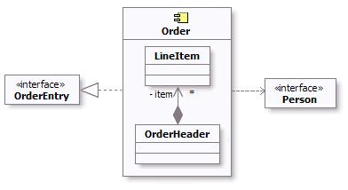
Example component diagram for Order Subsystem
As a component is a structured class, it can be tightly encapsulated by forcing communications from outside to pass through ports obeying declared interfaces, which brings additional precision in specification and interconnection for that component. This representation allows us to “wire” instances of parts through connectors to play a specific role in the component implementation (refer to Concepts: Structured Class for additional information).
An example of composite structure diagram for the Order subsystem using interfaces and ports is shown below.
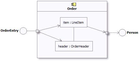
Example composite structure diagram for Order Subsystem
In addition, a statechart diagram may be needed to document the possible states the subsystem can assume, see Guidelines: Statechart Diagram.
The description of the classes contained in the subsystem itself is handled in the Activity: Class Design.
Describe Subsystem Dependencies
| Purpose | To document the interfaces upon which the subsystem is dependent. |
When an element contained by a subsystem uses some behavior of an element contained by another subsystem, a dependency is created between the enclosing subsystems. To improve reuse and reduce maintenance dependencies, we want to express this in terms of a dependency on a particular interface of the subsystem, not upon the subsystem itself nor on the element contained in the subsystem.
The reason for this is two-fold:
- We want to be able to substitute one model element (including subsystems) for one another as long as they offer the same behavior. We specify the required behavior in terms of interfaces, so any behavioral requirements one model element has on another should be expressed in terms of interfaces.
- We want to allow the designer total freedom in designing the internal behavior of the subsystem so long as it provides the correct external behavior. If a model element in one subsystem references a model element in another subsystem, the designer is no longer free to remove that model element or redistribute the behavior of that model element to other elements. As a result, the system is more brittle.
In creating dependencies, ensure that there are no direct dependencies or associations between model elements contained by the subsystem and model elements contained by other subsystems. Also ensure that there are no circular dependencies between subsystems and interfaces; a subsystem cannot both realize an interface and be dependent on it as well.
Dependencies between subsystems, and between subsystems and packages, can be drawn directly as shown below. When shown this way, the dependency states that one subsystem (Invoice Management, for example) is directly dependent on another subsystem (Payment Scheduling Management).
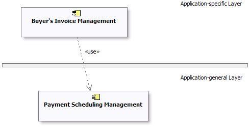
Example of Subsystem Layering using direct dependencies
When there is a potential for substitution of one subsystem for another (where they have the same interfaces), the dependency can be drawn to an **interface**realized by the subsystem, rather than to the subsystem itself. This allows any other model element (subsystem or class) which realizes the same interface to be used. Using interface dependencies allows flexible frameworks to be designed using replaceable design elements.
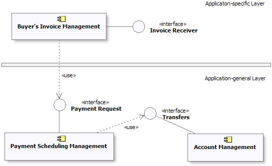
Example of Subsystem Layering using Interface dependencies
UML 1.x Representation
The same considerations about [subsystem dependencies](#Describe Subsystem Dependencies) apply if UML 1.5 notation is being used:
Example of Subsystem Layering using direct dependencies
Example of Subsystem Layering using Interface dependencies
Refer to Differences Between UML 1.x and UML 2.0for more information.
Activity: Support Development
| Purpose - To support the development with hardware and software. | |
| Role: System Administrator | |
| **Frequency:**On-going. | |
| Input Artifacts: - Development Infrastructure - Test Environment Configuration - Tools | Resulting Artifacts: - Development Infrastructure |
| Tool Mentors: - Adding Templates to Your Rational RequisitePro Project - Archiving Requirements Using Rational RequisitePro - Configuring Projects Using the Rational Administrator - Configuring the Test Environment in Rational Test RealTime - Creating Multiple Sites Using Rational ClearCase - Creating Multiple Sites Using Rational ClearQuest - Setting Up for a Project Using Rational XDE Developer - .NET Edition - Setting Up for a Project Using Rational XDE Developer - Java Platform Edition - Setting Up Rational RequisitePro for a Project - Setting Up Rational Rose for a Project - Setting Up the Test Environment in Rational Robot - Setting Up the Test Environment in Rational TestFactory |
| Workflow Details: - Deployment - Manage Acceptance Test - Environment - Support Environment During an Iteration - Support Environment During an Iteration |
This activity regroups a large range of technical services such as: maintaining the development infrastructure, both hardware and software, system administration, backup, telecommunications, document creation and reproduction, and so on.
Activity: Tailor the Process for the Project
| Workflow Details: - Environment - Prepare Environment for Project |
Analyze the Project
| Purpose: | To get a feel for the problem at hand, and the resources available to the project. |
It is crucial for the success of the project that the development process is relevant for the project at hand, and for the size and formality requirements of the project. Too much process tends to get in the way of creativity and efficiency. Too little process can lead to a chaotic environment, typically leading individual project members to make local decisions that may result in inefficient, inconsistent and unpredictable results.
Process ceremony varies a lot in different development organizations. Some are very process mature, and have dedicated process groups to look after the definition and improvements of the development process throughout the organization. Others are concerned with project-specific tailoring only. These projects will typically start with one of the predefined configurations that come with the RUP product, and from there instantiate the process for every project. The approach taken to tailor the process for the project, depends heavily on several factors, for instance :
- The development organization’s process maturity.
- The size of the project in terms of calendar time and number of development resources.
- The project members previous exposure to similar processes.
- The formality requirements of the project.
See Guideline: Process Discriminants for details.
An assessment of the development organization, if available, indicates which areas the development organization as a whole needs to focus on. An informed decision on which of the identified improvement areas should be targeted for the upcoming project needs to be made. This is further discussed in the next section Define the Scope of the Process. See also Artifact: Development-Organization Assessment for further details.
Define the Scope of the Process
| Purpose: | Define which process areas to cover in the project-specific process. |
The results of analyzing the project resources and their experience with similar software development projects helps identify the scope of the tailoring effort. A project-specific process does not have to include all the disciplines in RUP, nor should it be necessary to cover all the roles defined in the RUP. Keep in mind that the RUP is a process framework suitable for a wide range of project types, and thus will be too much for one specific project to follow. Which areas you select to cover in the project’s process, depends heavily upon the existing skill sets of the project members, and the nature of the project at hand. Below are some typical considerations to make when defining the scope of the tailoring effort.
- Areas where the project members already have a common way of working, where it is not necessary to introduce a new process and tools. For example, if they know how to test, it can be a good idea to not introduce the Test discipline of the RUP to limit the number of new factors. You can focus on introducing some parts of the RUP, to correct problems in their existing process. See [Concepts: Implementing a Process in a Project, section “Improving Process and Tools”](../disciplines/environment/co_iproj.md#Improving Process and Tools), for details.
- Areas (disciplines) where the project must introduce new process and tools, because there is no existing way of working. In some cases there is no existing process and tools to fall back on, and it is necessary to introduce most of the RUP, together with supporting tools. See [Concepts: Implementing a Process in a Project, section “Change Everything”](../disciplines/environment/co_iproj.md#Change Everything), for details.
- Problems in the existing process. Focus on improving areas in which the organization has had problems.
- Which tools to use ? If the project has decided to use certain tools, the development process should normally cover the corresponding areas of the RUP.
- The project’s capacity to change. When looking at the organization’s problems there is a tendency to try to fix everything at once, especially since many of these problems occur together. This is usually a fatal trap. Organizations just like individuals can accommodate change but only within a limited range. If the capacity to change is low, you have to go slower, and maybe just introduce one or two disciplines of the RUP in the first project.
- Areas where the project’s members lack knowledge, or are weak. Let the development process cover these areas. Make sure that it is easy to find the right information in the RUP.
Identified improvement areas must not necessarily be introduced for the first time in the same project. Reduce the number of unknown factors and look at areas where the development organization has experienced the most pain in the past. We recommend that you implement the RUP iteratively, as described in the Concepts: Implementing a Process in a Project. Although there might be discovered needs for improvements within several disciplines, consider the option of introducing them iteratively over the course of several projects rather than aiming for a change-everything-at-once approach.
One example of such a tradeoff is to introduce Requirements with Use-cases and defer the introduction of a new CM process, if previous projects have struggled with unclear and/or insufficient requirements, or if major complaints have been made by end-users that the delivered product does not meet their needs.
The tradeoffs made should be documented to communicate the scoping decisions to external stakeholders. When creating the configuration in the RUP Builder product, these decisions can be documented as a description of the configuration and will surface in the published Website. You can also decide to document this in the project’s Development Case under the section titled “Scope”.
Extend the Process Framework (optional)
| Purpose: | To add additional process know-how to the project-specific process, in areas where the coverage in the RUP process framework is deemed insufficient for the project. |
One of the strengths of the RUP process framework is that it is applicable
to a wide range of projects and environments. But this may at the same time
be perceived as a disadvantage too, because the process description tends to
become a bit too generic. The RUP plug-in technology is designed to overcome
some of these issues by allowing tool or technology vendors and individual companies
to create more specific process descriptions through plug-ins. You will find an
up-to-date list of plug-ins available for download in the RUP section of developerWorks®: Rational®.
The Rational Process Workbench(TM) (RPW) product enables the creation of RUP extensions using the RUP Plug-in technology. Following the recommendations for this technology, the RUP framework can be extended in two ways. You either create a structural plug-in to extend the RUP process model, or you create extensions that will provide a development organization’s relevant reusable assets to the project through thin plug-ins.
Creating a RUP plug-in (structural) should be treated as a project in its own right, with separate plans, budget and control mechanisms. You should define a business case for it, based on return-on-investment analysis. The actual development of the plug-in will benefit from following the lifecycle and disciplines in the RUP. We recommend that you try out the main ideas behind the plug-in on a real project before you start the project to develop the plug-in.
See Guideline: RUP Tailoring, section Extend the RUP, for more information.
Configure the Process
| Purpose: | To right-size the process to support the exact needs of a project. |
The RUP framework is built up of a set of process components and plug-ins, each component contains a set of related process elements. Creating a RUP configuring means selecting between a set of process components. Selecting the rightset of components for a given project is not a trivial task. To be effective, the process needs to be relevant and right-sized along different dimensions, like project size (resources and calendar time), formality, technological platform, domain, just to mention a few.
For more detailed information on configuring RUP, refer to
- Concept: RUP Tailoring, section Create a RUP Configuration
- Tool Mentor: Configure Process Using RUP Builder
- The Process Engineering Process (PEP) component of the Rational Process Workbench(TM) (RPW) product
Prepare the Process for the Project
| Purpose: | To define how the configured process is enacted in the project. |
A process description configured for a project is often not at the level of details ready to be enacted. For example, the process defines a set of artifacts to use based on a selection of relevant process components (as described in the previous section Create a RUP Configuration), but it does not specify timing and formality requirements of the artifacts for this particular project. Prescriptive guidelines and partially instantiated artifact templates are also considered to be part of an instantiated project-specific process. The required effort to perform this step is highly dependent on the precision of the configured process. Any such deviation from the underlying process should be justified and documented as part of the project-specific process.
The work of instantiating the configured is described in detail in the following activities, all performed by the Process Engineer :
- See Activity: Develop Development Case for guidance on how to define lifecycle model and selection and tailoring of artifacts.
- See Activity: Prepare Guidelines for the Projectfor guidance on harvesting and tailoring of project-specific guidelines.
- See Activity: Prepare Templates for the Project for guidance on harvesting and tailoring of project-specific templates.
Introduce the Process to the Project Members
| Purpose: | To make the project-specific process available to the project’s members. |
After the initial tailoring work is done, the resulting process needs to be published into a consumable format. The RUP Builder product provides a means to publish the configured process resulting in a RUP Website that contains only the selected process components and resources. See Tool Mentor: Publish Process Configuration Using RUP Builder for tool specific guidance. The Process Engineer needs to work with the Project Manager to make the project-specific process public, and decide on how to educate the project members. This can vary from an informal 2 hour presentation to more formal training, depending on the size of the project and the project members’ familiarity with similar development processes. Every significant update of the process during the project lifecycle, should be re-launched to the project, focusing on the changes.
The Website for the project-specific process can be published to a Web server on the organization’s network, or installed on each individual team member’s computer. If the project members are connected to the network most of the time, then deploying the RUP Website to a Web server is recommended to avoid any overhead associated with updates to the process during the project lifecycle.
See Activity: Launch Development Process for further information.
Maintain the Process
Although the bulk of the tailoring work is done in the early days of the project, it should be kept up-to-date continuously, as the project teams uncover obstacles and other issues in the process. Assessments made during the project are important input to improving the process. Minor adjustments are typically handled by the project, and updates to the project-specific process are made as part of preparing the development environment for the upcoming iteration. These kind of process improvements will often lead to updates being made to artifacts, such as development case, project-specific guidelines and project-specific templates. More complex issues are raised as change requests on the process. This is usually handled by a process group outside the boundaries of the project, that has the responsibility of the software development process on an organizational basis.
One of the major benefits of iterative development is that it allows the project teams to gradually improve the way they develop software. We recommend that every project include process engineering micro-cycles consisting of the following steps :
- Define process
- Perform project work based on defined process
- Assess your work
- Refine process
The Process Engineering Process within the Rational Process Workbench product contains information on Process Improvement in an organizational setting.
Activity: Update Change Request
| Input Artifacts: - Change Request | Resulting Artifacts: - Change Request |
Retrieve the Change Request Form
The Change Request Form is a formally submitted artifact that is used to track all requests (including new features, enhancement requests, defects, changed requirements, etc.) along with related status information throughout the project lifecycle. All change history will be maintained with the CR, including all state changes along with dates and reasons for the change. This information will be available for any repeat reviews and for final closing. An example Change Request Form is provided in Artifact: Change Requests.
Update and Resubmit the Change Request
If more information is needed (More Info) to evaluate a CR, or if a CR is rejected at any point in the process (e.g., confirmed as a Duplicate, Reject, etc.), the submitter is notified and may update the CR with new information. The updated CR is then re-Submitted to the CCB Review Queue for consideration of the new data.
Typical states that a Change Request may pass through are shown in Concepts: Change Request Management)
Activity: Update Workspace
| Input Artifacts: - Project Repository - Workspace | Resulting Artifacts: - Workspace |
It is an essential part of any CM system to ensure that artifacts are under version control, and that team members have access to approved baselines. The idea of updating views to ensure access to the most recent collective body of work is obvious. This activity needs to be easy to do and occur on an ongoing basis.
Each team member having updated a view, can work on any artifact through the standard process of ‘check-out, edit, build, unit test, and check-in’ as described in the Activity: Make Changes.
Activity: Use-Case Design
| Purpose - To refine use-case realizations in terms of interactions - To refine requirements on the operations of design classes - To refine requirements on the operations of design subsystems and/or their interfaces - To refine requirements on the operations of capsules | |
| Role: Designer | |
| Frequency: Once per iteration, for a set of Artifact: Design Use-Case Realizations. | |
| Steps - [Create Use-Case Realizations](#Create Use-Case Realizations) - [Describe Interactions Between Design Objects](#Describe Interactions Between Design Objects) - [Simplify Sequence Diagrams Using Subsystems](#Simplify Sequence Diagrams Using Subsystems (optional)) - [Describe Persistence-Related Behavior](#Describe Persistence-Related Behavior) - [Refine the Flow of Events Description](#Refine the Flow of Events Description) - [Unify Design Classes and Subsystems](#Unify Classes and Subsystems) - [Evaluate Your Results](#Evaluate Your Results) | |
| Input Artifacts: - Analysis Model - Capsule - Design Class - Design Model - Design Subsystem - Interface - Supplementary Specifications - Use Case - Use-Case Realization | Resulting Artifacts: - Design Model - Use-Case Realization |
| Tool Mentors: - Creating Use-Case Realizations Using Rational Rose - Designing Use Cases Using Rational XDE Developer - .NET Edition - Designing Use Cases Using Rational XDE Developer - Java Platform Edition - Managing Collaboration Diagrams Using Rational Rose - Managing Sequence Diagrams Using Rational Rose - Managing the Design Model Using Rational Rose | |
| More Information: - Guideline: Sequence Diagram - Guideline: Statechart Diagram - Guideline: Use-Case Realization | |
| - UML 1.x Representation |
| Workflow Details: - Analysis & Design - Design Components |
The behavior of a system can be described using a number of techniques - collaborations or interactions. This activity describes the use of interactions, specifically sequence diagrams, to describe the behavior of the system. Sequence diagrams are most useful where the behavior of the system or subsystem can be primarily described by synchronous messaging. Asynchronous messaging, especially in event-driven systems, is often more easily described in terms of state machines and collaborations, allowing a compact way of defining possible interactions between objects.
Asynchronous messages play an important role in real-time or reactive systems, and are used for communication between instances of Artifact: Capsules.
Create Use-Case Realizations
The Artifact: Design Use-Case Realization provides a way to trace behavior in the Design Model back to the Use-Case Model, and it organizes collaborations in the Design Model around the Use-Case concept.
Create a Design Use-Case Realization in the Design Model for each Use Case to be designed. The name for the Design Use-Case Realization should be the same as the associated Use Case, and a “realizes” relationship should be established from the use-case realization to its associated use case.
Describe Interactions Between Design Objects
For each use-case realization, you should illustrate the interactions between its participating design objects by creating one or more sequence diagrams. Early versions of these may have been created during Activity: Use-Case Analysis. Such “analysis versions” of the use-case realizations describe interactions between analysis classes. They need to be evolved to describe interactions between design elements.
Updating the sequence diagrams involves the following steps:
-
Identify each object that participates in the flow of the use case. This is done by instantiating the design classes and subsystems identified in the Activity: Identify Design Elements. In real-time systems, you will also be identifying the capsule instances that participate in the flow of the use case.
-
Represent each participating object in a sequence diagram. Make a lifeline for each participating object in the sequence diagram. In order to represent the design subsystems you have some choices:
- You can show instances of the subsystem on the sequence diagram.
- You can use the interfaces realized by the subsystem. This is preferred in cases where you’d like to show that any model element which realizes the same interface might be used in place of the interface. If you choose to show interfaces on the sequence diagram, be aware that you will want to ensure that no messages are sent from the interface to other objects. The reason for this is that interfaces completely encapsulate the internal realization of their operations. Therefore, we cannot be certain that all model elements which realize the interface will in fact actually be designed the same way. So on sequence diagrams no messages should be shown being sent from interfaces.
- You can use the component to represent the subsystem on sequence diagrams. Use the component in cases where you want to show that a specific subsystem responds to a message. In this case, you can show messages being sent from the component to other objects.
Note that these are system-level sequence diagrams, which show how instances of top level design elements (typically subsystems and subsystem interfaces) interact. Sequence diagrams showing the internal design of subsystems are produced separately, as part of Activity: Subsystem Design.
-
Note that active object interactions are typically described using specification collaborations and state machines. They would be used here to show how messages can be sent to active objects by other elements in the system in a larger use-case realization. In typical usage, active objects are encapsulated within subsystems for the purpose of this activity, such that the use-case realization consists of a set of interacting subsystems. The interactions define the responsibilities and interfaces of the subsystems. Within the subsystems, active objects represent concurrent threads of execution. The subsystems allow work to be divided between development teams, with the interfaces serving as the formal contracts between the teams.
For real-time systems, you will use Artifact: Capsules to represent the active objects.
A minor note on showing messages emanating from subsystems: restricting messages only to interfaces reduces coupling between model elements and improves the resiliency of the design. Where possible, you should try to achieve this, and in cases where there are messages emanating from subsystems to non-interface model elements, you should look for opportunities to change these to messages to interfaces to improve decoupling in the model.
-
Represent the interaction that takes place with actors. Represent each actor instance and external object that the participating objects interacts with by a lifeline in the sequence diagram.
-
Illustrate the message sending between participating objects. The flow of events begins at the top of the diagram and continues downward, indicating a vertical chronological axis. Illustrate the message sending between objects by creating messages (arrows) between the lifelines. The name of a message should be the name of the operation invoked by the message. In the early stages of design, not many operations will be assigned to the objects, so you may have to leave this information out and give the message a temporary name; such messages are said to be “unassigned.” Later, when you have found more of the participating objects’ operations, you should update the sequence diagram by “assigning” the messages with these operations.
-
Describe what an object does when it receives a message. This is done by attaching a script to the corresponding message. Place these scripts in the margin of the diagram. Use either structured text or pseudocode. If you use pseudocode, be sure to use constructs in the implementation language so that the implementation of the corresponding operations will be easier. When the person responsible for an object’s class assigns and defines its operations, the object’s scripts will provide a basis for that work.
You document the use-case behavior performed by the objects in a sequence diagram.
When you have distributed behavior among the objects, you should consider how the flow will be controlled. You found the objects by assuming they would interact a certain way in the use-case realization, and have a certain role. As you distribute behavior, you can begin to test those assumptions. In some parts of the flow, you might want to use a decentralized structure; in others, you might prefer a centralized structure. For definitions of these variants and recommendations on when to use the two types of structure, see [Guidelines: Sequence Diagrams](../modeling_guides/md_seqdm.md#Distributing Control).
You might need new objects at this point, for example if you are using a centralized structure and need a new object to control the flow. Remember that any object you add to the design model must fulfill the requirements made on the object model.
Incorporate Applicable Design Mechanisms
During Activity: Architectural Analysis, analysis mechanisms were identified. During Activity: Identify Design Mechanisms, analysis mechanisms re refined into design mechanisms, the mapping from the analysis mechanisms to the design mechanisms is captured in the Software Architecture Document, and the design mechanisms are documented in the Project Specific Guidelines.
During this activity, Use-Case Design, any applicable design mechanisms are incorporated into the use-case realizations. The Designer surveys the available design mechanisms and determines those that apply to the use-case realization being developed, working within the recommendations and guidelines documented in the Software Architecture Document and the Design Guidelines. Note: Applicable design mechanism may have been identified in Activity: Use-Case Analysis, during which analysis classes may have been “tagged” with a particular analysis mechanism, indicating that a particular piece of functionality needed to be handled in the design. In such a case, the applicable design mechanisms are those associated with the analysis mechanisms that analysis classes participating in the use-case realization were tagged with
The Designer incorporates the applicable design mechanisms into the use-case realizations by including the necessary design elements and design element interactions into the use-case realizations following the rules of use documented in the Design Guidelines.
Handle All Variants of the Flow of Events
You should describe each flow variant in a separate sequence diagram. Sequence diagrams are generally preferable to communication diagram as they tend to be easier to read when the diagram must contain the level of detail we typically want in when designing the system.
Start with describing the basic flow, which is the most common or most important flow of events. Then describe variants such as exceptional flows. You do not have to describe all the flows of events, as long as you employ and exemplify all operations of the participating objects. Given this, very trivial flows can be omitted, such as those that concern only one object.
Study the use case to see if there are flow variants other than those already described in requirements capture and analysis, for example, those that depend on implementation. As you identify new flows, describe each one in a sequence diagram. Examples of exceptional flows include the following.
- Error handling. If an interface reports that an error has occurred in its communication with some external system, for example, the use case should deal with this. A possible solution is to open a new communication route.
- Time-out handling. If the user does not reply within a certain period, the use case should take some special measures.
- Handling of erroneous input to the objects that participate in the use case. Errors like this might stem from incorrect user input.
Handle Optional Parts of the Use Case
You can describe an alternative path of a flow as an optional flow instead of as a variant. The following list includes two examples of optional flows.
- By sending a signal, the actor decides-from a number of options-what the use case is to do next. The use case has asked the actor to answer yes or no to a question, for example, or provided the actor with a variety of functions the system can perform in the use case’s current state.
- The flow path varies depending on the value of stored attributes or relationships. The subsequent flow of events depends on the type of data to be processed.
If you want an optional flow, or any complex sub-flow, to be especially noticeable, use a separate sequence diagram. Each separate sequence diagram should be referred to from the sequence diagram for the main flow of events using scripts, margin text or notes to indicate where the optional or sub-flow behavior occurs.
In cases where the optional or exceptional flow behavior could occur anywhere, for example behavior which executes when a particular event occurs, the sequence diagram for the main flow of events should be annotated to indicate that when the event occurs, the behavior described in the optional/exceptional sequence diagram will be executed. Alternately, if there is significant event-driven behavior, consider using statechart diagrams to describe the behavior of the system. For more information, see Guidelines: Statechart Diagram.
Simplify Sequence Diagrams Using Subsystems (optional)
When a use case is realized, the flow of events is usually described in terms of the executing objects, i.e. as interaction between design objects. To simplify diagrams and to identify re-usable behavior, there may be a need to encapsulate a sub-flow of events within a subsystem. When this is done, large subsections of the sequence diagram are replaced with a single message to the subsystem. Within the subsystem, a separate sequence diagram may illustrate the internal interactions within the subsystem that provide the required behavior (for more information, see Activity: Subsystem Design).
Sub-sequences of messages within sequence diagrams should be encapsulated within a subsystem when:
- The sub-sequence occurs repeatedly in different use-case realizations; that is, the same (or similar) messages are sent to the same (or similar) objects, providing the same end result. The phrase ‘similar’ is used because some design work might be needed to make the behavior reusable.
- The sub-sequence occurs in only one use-case realization, but it is expected to be performed repeatedly in future iterations, or in similar systems in the future. The behavior might make a good reusable component.
- The sub-sequence occurs in only one use-case realization, but is complex but easily encapsulated, needs to be the responsibility of one person or a team, and provides a well-defined result. In these kinds of situations, the complex behavior usually requires special technical knowledge, or special domain knowledge, and as a result is well-suited to encapsulating it within a subsystem.
- The sub-sequence is determined to be encapsulated within a replaceable component (see Concepts: Component). In this case, a subsystem is the appropriate representation for the component within the design model.
A use-case realization can be described, if necessary, at several levels in the subsystem hierarchy. The lifelines in the middle diagram represent subsystems; the interactions in the circles represent the internal interaction of subsystem members in response to the message.
The advantages of this approach are:
- Use-case realizations become less cluttered, especially if the internal design of some subsystems is complex.
- Use-case realizations can be created before the internal designs of subsystems are created; this is useful for example in parallel development environments (see “[How to Work in Parallel](#How to Work in Parallel)”).
- Use-case realizations become more generic and easy to change, especially if a subsystem needs to be substituted with another subsystem.
Example:
Consider the following sequence diagram, which is part of a realization of the Local Call use case:
In this diagram, the gray classes belong to a Network Handling subsystem; the other classes belong to a Subscriber Handling subsystem. This implies that this is a multi-subsystem sequence diagram, i.e. a diagram where all the objects that participate in the flow of events are included, regardless of whether their classes lie in different subsystems or not.
As an alternative, we can show invocation of behavior on the Network Handling subsystem, and the exercise of a particular interface on that subsystem. Let’s assume that the Network Handling subsystem provides an ICoordinator interface, which is used by the Subscriber Handling subsystem:
The ICoordinator interface is realized by the Coordinator class within Network Handling. Given this, we can use the Network Handling subsystem itself and its ICoordinator interface in the sequence diagram, instead of instances of classes within Network Handling:
Note that the Coordinator, Digit Information, and Network class instances are substituted by their containing subsystem. All calls to the subsystem are instead done via the ICoordinator interface.
Showing Interfaces on Lifelines
In order to achieve true substitutability of subsystems realizing the same interface, only their interface should be visible in interactions (and in diagrams in general); otherwise the interactions (or diagrams) need to be changed when subsystems are substituted with each other.
Example:
We can include only the ICoordinator interface, but not its providing subsystem, in a sequence diagram:
Sending a message to an interface lifeline means that any subsystem which realizes the interface can be substituted for the interface in the diagram. Note that the ICoordinator interface lifeline does not have messages going out from it, since different subsystems realizing the interface might send different messages. However, if you want to describe what messages should be sent (or are allowed to be sent) from any subsystem realizing the interface, such messages can go out from the interface lifeline.
How to Work in Parallel
In some cases it can be appropriate to develop a subsystem more or less independently and in parallel with the development of other subsystems. To achieve this, we must first find subsystem dependencies by identifying the interfaces between them.
The work can be done as follows:
- Concentrate on the requirements that affect the interfaces between the subsystems.
- Make outlines of the required interfaces, showing the messages that are going to pass over the subsystem borders.
- Draw sequence diagrams in terms of subsystems for each use case.
- Refine the interfaces needed to provide messages.
- Develop each subsystem in parallel, and use the interfaces as synchronization instruments between development teams.
You can also choose whether to arrange the sequence diagrams in term of subsystems or in terms of their interfaces only. In some projects, it might even be necessary to implement the classes providing the interfaces before you continue with the rest of the modeling.
Describe Persistence-Related Behavior
The whole goal of the object-oriented paradigm is to encapsulate implementation details. Therefore, with respect to persistence, we would like to have a persistent object look just like a transient object. We should not have to be aware that the object is persistent, or treat it any differently than we would any other object. At least that’s the goal.
In practice, there might be times when the application needs to control various aspects of persistence:
- when persistent objects are read and written
- when persistent objects are deleted
- how transactions are managed
- how locking and concurrency control is achieved
Writing Persistent Objects
There are two cases to be concerned with here: the initial time the object is written to the persistent object store, and subsequent times when the application wants to update the persistent object store with a change to the object.
In either case, the specific mechanism depends on the operations supported by the persistence framework. Generally, the mechanism used is to send a message to the persistence framework to create the persistent object. Once an object is persistent, the persistence framework is smart enough to detect subsequent changes to the persistent object and write them to the persistent object store when necessary (usually when a transaction is committed).
An example of a persistent object being created is shown below:
The object PersistenceMgr is an instance of VBOS, a persistence framework. The OrderCoordinator creates a persistent Order by sending it as the argument to a ‘createPersistentObject’ message to the PersistenceMgr.
It is generally not necessary to explicitly model this unless it is important to know that the object is being explicitly stored at a specific point in some sequence of events. If subsequent operations need to query the object, the object must exist in the database, and therefore it is important to know that the object will exist there.
Reading Persistent Objects
Retrieval of objects from the persistent object store is necessary before the application can send messages to that object. Recall that work in an object-oriented system is performed by sending messages to objects. But if the object that you want to send a message to is in the database but not yet in memory, you have a problem: you cannot send a message to something which does not yet exist!
In short, you need to send a message to an object that knows how to query the database, retrieve the correct object, and instantiate it. Then, and only then, can you send the original message you originally intended. The object that instantiates a persistent object is sometimes called a factory object. A factory object is responsible for creating instances of objects, including persistent objects. Given a query, the factory could be designed to return a set of one or more objects which match the query.
Generally objects are richly connected to one another through their associations, so it is usually only necessary to retrieve the root object in an object graph; the rest are essentially transparently ‘pulled’ out of the database by their associations with the root object. (A good persistence mechanism is smart about this: it only retrieves objects when they are needed; otherwise, we might end up trying to instantiate a large number of objects needlessly. Retrieving objects before they are needed is one of the main performance problems caused by simplistic persistence mechanisms.)
The following example shows how object retrieval from the persistent object store can be modeled. In an actual sequence diagram, the DBMS would not be shown, as this should be encapsulated in the factory object.
Deleting Persistent Objects
The problem with persistent objects is, well, they persist! Unlike transient objects which simply disappear when the process that created them dies, persistent objects exist until they are explicitly deleted. So it’s important to delete the object when it’s no longer being used.
Trouble is, this is hard to determine. Just because one application is done with an object does not mean that all applications, present and future, are done. And because objects can and do have associations that even they don’t know about, it is not always easy to figure out if it is okay to delete an object.
In design, this can be represented semantically using state charts: when the object reaches the end state, it can be said to be released. Developers responsible for implementing persistent classes can then use the state chart information to invoke the appropriate persistence mechanism behavior to release the object. The responsibility of the Designer of the use-case realization is to invoke the appropriate operations to cause the object to reach its end state when it is appropriate for the object to be deleted.
If an object is richly connected to other objects, it might be difficult to determine whether the object can be deleted. Since a factory object knows about the structure of the object as well as the objects to which it is connected, it is often useful to charge the factory object for a class with the responsibility of determining whether a particular instance can be deleted. The persistence framework can also provide support for this capability.
Modeling Transactions
Transactions define a set of operation invocations which are atomic; they are either all performed, or none of them are performed. In the context of persistence, a transaction defines a set of changes to a set of objects which are either all performed or none are performed. Transactions provide consistency, ensuring that sets of objects move from one consistent state to another.
There are several options for showing transactions in Use Case Realizations:
- Textually. Using scripts in the margin of the sequence diagram, transaction boundaries can be documented as shown below. This method is simple, and allows any number of mechanisms to be used to implement the transaction.
Representing transaction boundaries using textual annotations.
- Using Explicit Messages. If the transaction management mechanism being used uses explicit messages to begin and end transactions, these messages can be shown explicitly in the sequence diagram, as shown below:
A sequence diagram showing explicit messages to start and stop transactions.
Handling Error Conditions
If all operations specified in a transaction cannot be performed (usually because an error occurred), the transaction is aborted, and all changes made during the transaction are reversed. Anticipated error conditions often represent exceptional flows of events in use cases. In other cases, error conditions occur because of some failure in the system. Error conditions should be documented in interactions was well. Simple errors and exceptions can be shown in the interaction where they occur; complex errors and exception may require their own interactions.
Failure modes of specific objects can be shown on state charts. Conditional flow of control handling of these failure modes can be shown in the interaction in which the error or exception occurs.
Handling Concurrency Control
Concurrency describes the control of access to critical system resources in the course of a transaction. In order to keep the system in a consistent state, a transaction may require that it have exclusive access to certain key resources in the system. The exclusivity may include the ability to read a set of objects, write a set of objects, or both read and write a set of objects.
Let’s look at a simple example of why we might need to restrict access to a set of objects. Let’s say we a running a simple order entry system. People call-in to place orders, and in turn we process the orders and ship the orders. We can view the order as a kind of transaction.
To illustrate the need for concurrency control, let’s say I call in to order a new pair of hiking boots. When the order is entered into the system, it checks to see if the hiking boots I want, in the correct size, are in inventory. If they are, we want to reserve that pair, so that no one else can purchase them before the order can be shipped out. Once the order is shipped, the boots are removed from inventory.
During the period between when the order is placed and when it ships, the boots are in a special state—they are in inventory, but they are “committed” to my order. If my order gets canceled for some reason (I change my mind, or my credit card has expired), the boots get returned to inventory. Once the order is shipped, we will assume that our little company does not want to keep a record that it once had the boots.
The goal of concurrency, like transactions, is to ensure that the system moves from one consistent state to another. In addition, concurrency strives to ensure that a transaction has all the resources it needs to complete its work. Concurrency control may be implemented in a number of different ways, including resource locking, semaphores, shared memory latches, and private workspaces.
In an object-oriented system, it is difficult to tell from just the message patterns whether a particular message might cause a state change on an object. Also, different implementations may obviate the need to restrict access to certain types of resources; for example, some implementations provide each transaction with its own view of the state of the system at the beginning of the transaction. In this case, other processes may change the state of and object without affecting the ‘view’ of any other executing transactions.
To avoid constraining the implementation, in design we simply want to indicate the resources to which the transaction must have exclusive access. Using our earlier example, we want to indicate that we need exclusive access to the boots that were ordered. A simple alternative is to annotate the description of the message being sent, indicating that the application needs exclusive access to the object. The Implementer then can use this information to determine how best to implement the concurrency requirement. An example sequence diagram showing annotation of which messages require exclusive access is shown below. The assumption is that all locks are released when the transaction is completed.
An example showing annotated access control in a sequence diagram.
The reason for not restricting access to all objects needed in a transaction is that often only a few objects should have access restrictions; restricting access to all objects participating in a transaction wastes valuable resources and could create, rather than prevent, performance bottlenecks.
Refine the Flow of Events Description
In the flow of events of the use-case realization you may need to add additional description to the sequence diagrams, in cases where the flow of events is not fully clear from just examining the messages sent between participating objects. Some examples of these cases include cases where timing annotations, notes on conditional behavior, or clarification of operation behavior is needed to make it easier for external observers to read the diagrams.
The flow of events is initially outlined in the Activity: Use-Case Analysis. In this step you refine the flow of events as needed to clarify the sequence diagrams.
Often, the name of the operation is not sufficient to understand why the operation is being performed. Textual notes or scripts in the margin of the diagram may be needed to clarify the sequence diagram. Textual notes and scripts may also be needed to represent control flow such as decision steps, looping, and branching. In addition, textual tags may be needed to correlate extension points in the use case with specific locations in sequence diagrams.
Previous examples within this activity have illustrated a number of different ways of annotating sequence diagrams.
Unify Design Classes and Subsystems
As use cases are realized, you need to unify the identified design classes and subsystems to ensure homogeneity and consistency in the Design Model.
Points to consider:
- Names of model elements should describe their function.
- Avoid similar names and synonyms because they make it difficult to distinguish between model elements.
- Merge model elements that define similar behavior, or that represent the same phenomenon.
- Merge entity classes that represent the same concept or have the same attributes, even if their defined behavior is different.
- Use inheritance to abstract model elements, which tends to make the model more robust.
- When updating a model element, also update the corresponding flow of events description of the use-case realizations.
Evaluate Your Results
You should check the design model at this stage to verify that your work is headed in the right direction. There is no need to review the model in detail, but you should consider the Checkpoints for the Design Model while you are working on it.
See especially checkpoints for use-case realization in the Activity: Review the Design.
UML 1.x Representation
You can use a proxy class to represent the subsystem on sequence diagrams. This proxy class is contained within the subsystem and is used to represent the subsystem in diagrams which do not support the direct use of packages and subsystems as behavioral elements. Use the proxy class in cases where you want to show that a specific subsystem responds to a message. In this case, you can show messages being sent from the subsystem proxy to other objects.
Refer to Differences Between UML 1.x and UML 2.0for more information.
Activity: Verify Changes in Build
| Input Artifacts: - Build - Change Request - Test Log | Resulting Artifacts: - Change Request - Test Results |
Resolve Change Request
The Assigned role performs the set of activities defined within the appropriate section of the process (e.g., requirements, analysis & design, implementation, produce user-support materials, design test, etc.) to make the changes requested. These activities will include all normal review and unit test activities as described within the normal development process. The CR will then be marked as Resolved. This signifies that the resolution of this CR is complete and is now ready for verification.
Verify Changes in Test Build
After the changes are Resolved by the assigned role (analyst, developer, tester, tech writer, and so on), the changes are placed into a test queue to be assigned to a tester and Verified in a test build of the product. A CR that has been Verified in a test build is ready to be included in a release. A CR that fails testing in either a test build or a release build will be placed in the Test Failed state. The owner automatically gets changed to the role who resolved the CR.
Verify Changes in Release Build
Once the resolved changes have been Verified in a test build of the product, the CR is placed into a release queue to be verified against a release build of the product, produce release notes, etc. and Close the CR.
A Closed CR no longer requires attention. This is the final state a CR can be assigned. Only the CCB Review Admin has the authority to close a CR. When a CR is Closed, the submitter will receive an email notification with the final disposition of the CR. A CR may be Closed: 1) after its Verifiedresolution is validated in a release build, 2) when its Rejected state is confirmed, or 3) when it is confirmed as a Duplicate of an existing CR. In the latter case, the submitter will be informed of the duplicate CR and will be added to that CR for future notifications (see the definitions of states “Rejected” and “Duplicate” for more details). If the submitter wishes to contest a closing, the CR must be updated and re-Submitted for CCB review.
Typical states that a Change Request may pass through are shown in Concepts: Change Request Management)
Evaluate and verify your results
| Purpose: | To verify that the activity has been completed appropriately and that the resulting artifacts are acceptable. |
Now that you have completed the work, it is beneficial to verify that the work was of sufficient value, and that you did not simply consume vast quantities of paper. You should evaluate whether your work is of appropriate quality, and that it is complete enough to be useful to those team members who will make subsequent use of it as input to their work. Where possible, use the checklists provided in RUP to verify that quality and completeness are “good enough”.
Have the people performing the downstream activities that rely on your work as input take part in reviewing your interim work. Do this while you still have time available to take action to address their concerns. You should also evaluate your work against the key input artifacts to make sure you have represented them accurately and sufficiently. It may be useful to have the author of the input artifact review your work on this basis.
Try to remember that that RUP is an iterative process and that in many cases artifacts evolve over time. As such, it is not usually necessary-and is often counterproductive-to fully-form an artifact that will only be partially used or will not be used at all in immediately subsequent work. This is because there is a high probability that the situation surrounding the artifact will change-and the assumptions made when the artifact was created proven incorrect-before the artifact is used, resulting in wasted effort and costly rework. Also avoid the trap of spending too many cycles on presentation to the detriment of content value. In project environments where presentation has importance and economic value as a project deliverable, you might want to consider using an administrative resource to perform presentation tasks.
Activity: Verify Manufactured Product
| Purpose - To ensure that the manufactured product is complete, and useable. This activity is sometimes referred to as the ‘first article inspection’. It serves as a quality control activity to ensure that the retailed product has all the required attributes and artifacts. | |
| Role: Deployment Manager | |
| Frequency: Once prior to ordering the production run, or distributing the product for customer use. | |
| Steps - Verify the Product against the Bill of Materials - Follow Product Installation Instructions - Check the Product for Usability - Ship the Product to Customers | |
| Input Artifacts: - Bill of Materials - Product | Resulting Artifacts: - Product |
| Tool Mentors: |
| Workflow Details: - Deployment - Package Product |
Verify the Product against the Bill of Materials
The Deployment Manager needs to be satisfied that the manufactured product is complete. Completion in this instance means that the product has all the constituent parts listed in the Bill of Materials. The Deployment Manager needs to go through the checklist and identify the product components.
Follow Product Installation Instructions
Having made sure that the manufactured product has all the required elements, the Deployment Manager has to ensure that the customer can load and run the software. This step is really a check to verify the clarity of installation instructions, and how well installation artifacts work in the final product.
Check the Product for Usability
Having installed the software, the Deployment Manager should go through the various tutorials and try out the product. The Deployment Manager should look at the product help features, and documentation to ensure that all is in order.
As an added precaution, the Deployment Manager should go through the exercise of reporting bugs, or calling the Help Line to check for responsiveness.
Ship Product to Customers
Assuming that the product passes the visual and usability tests, the Deployment Manager can sign-off the product release and make it available for shipment to customers. Product shipping is beyond the scope of a software development process, however, it is assumed that a software product development organization has established the right marketing channels and infrastructure for product distribution.
Activity: Verify Tool Configuration and Installation
| Purpose - To verify that the tools can be used to develop the system. | |
| Role: Tool Specialist | |
| Frequency: When new tools are introduced or changes have been made to existing tools. | |
| Steps: - [Verify the environment](#Verify the Environment) - [Verify the tools](#Verify the Tools) - [Verify data](#Verify Data) - [Run the tools](#Run the Tools) | |
| Input Artifacts: - Development Case - Development Infrastructure - Project Specific Guidelines - Tools | Resulting Artifacts: |
| Tool Mentors: |
| Workflow Details: - Environment - Prepare Environment for an Iteration |
The tools and the development infrastructure has to be verified before the project starts using them. How this is done will clearly vary dependent upon skills, technology, and tools.
Verify the Environment
Verify the environment contains the correct hardware, software, and data. Verify that the correct hardware is installed. This may be done visually or through a tool (such as using Windows Properties for My Computer).
Verify the Tools
Verify that the correct software configuration is installed. This may be done by looking at the registry settings, ‘ini’ files, or by launching the tool and looking at some information options or configuration options.
Verify Data
Verify the data contains the appropriate data. Verifying data may require using tools to visually inspect the data, or using an application to display the data. At some point, one or more use cases may be selected and executed (one or more scenarios) for each tool to ensure the tool and the results of using the tool are consistent with the need.
Run the Tools
Assemble a small team of people who know the tools and the project’s development case well, and let them run the tools.
- Test multi site, many colliding users
- At least one use case scenario for each tool has been executed to verify the appropriate installation and configuration of the tools.
- Try the normal scenarios in the development case and in the tool guidelines.
- Test the integration between different tools.
Issue change requests if necessary.
Activity: Write Configuration Management (CM) Plan
| Input Artifacts: - Development Case - Software Development Plan | Resulting Artifacts: - Configuration Management Plan |
Write the CM Plan
| Purpose | The CM Plan describes all CM related activities to be performed during the course of the product/project lifecycle. It details the schedule of activities, the assigned responsibilities, and the required resources (including staff, tools and computer facilities). |
The CM Plan is a composite document which contains all the information necessary to effectively carry out configuration management activities for the project. The Artifact: Configuration Management Plan describes the necessary input for effective CM planning. The template is intended to serve as a guideline. The intent of each section should be addressed within the context of a given project/product. It should not be an onerous task to produce the plan, nor is it intended that the plan impose undue ceremony and bureaucracy on the project staff.
However, the plan is an important document that is used to ensure that organizational assets are appropriately safeguarded.
Review and Approve the CM Plan
| Purpose | To ensure that plan is understood and adopted by the major stakeholders. |
The CM Plan is developed once the Project Vision and Business Case have been approved. It is written in parallel with other project planning documents by the Project Manager, and is reviewed by all affected groups.
Although the CM Plan is approved by the Project Manager, it needs to be reviewed by all affected parties. As such, it should be reviewed by the Configuration Manager, key developers and integrators.
Maintain the CM Plan
| Purpose | To ensure that the plan is current and relevant. |
The Project CM Plan should be re-visited at the beginning of each phase (construction and transition) to ensure that the overall CM strategy is still relevant to how the project is being developed.
The Project CM Plan itself needs to be placed under configuration control, and should be checked into the ‘plans’ sub-directory of the overall ‘Product Structure’.
Activity: Write Release Notes
| Purpose - To describe the major new features and changes in the release. The Release Notes should also describe any known bugs and limitations or workarounds to using the product. | |
| Role: Deployment Manager | |
| **Frequency:**Once per iteration | |
| Input Artifacts: - Bill of Materials - Deployment Plan - Integration Build Plan - Iteration Assessment | Resulting Artifacts: - Release Notes |
| Tool Mentors: |
| Workflow Details: - Deployment - Produce Deployment Unit |
Whereas the Bill of Materials provides a detailed list of what makes up the product, and the Integration Build Plan describes what is to contained for each build, Release Notes provide a summary of what changed since the last release. Release Notes are enclosed in the Deployment Unit / Product.
The suggestion is to create Release Notes for the Iteration Assessment at the end of each iteration. However, Release Notes could updated and maintained for each build, and then updated for the formal release of the product.
Checkpoints: Design Model
Topics
General
- The objectives of the model are clearly stated and visible.
- The model is at an appropriate level of detail given the model objectives.
- The model’s use of modeling constructs is appropriate to the problem at hand.
- The model is as simple as possible while still achieving the goals of the model.
- The model appears to be able to accommodate reasonably expected future change.
- The design is appropriate to the task at hand (neither too complex nor too advanced)
- The design appears to be understandable and maintainable
- The design appears to be implementable
Layers
- There are no more than seven (plus or minus two) layers.
- The rationale for layer definition is clearly presented and consistently applied.
- Layer boundaries are respected within the design.
- Layers are used to encapsulate conceptual boundaries between different kinds of services and provide useful abstractions which makes the design easier to understand.
Checkpoints: Design Package
- The name of each package is unique and descriptive of the collective responsibilities of the model elements which it contains.
- The package description accurately reflects the collective responsibilities of the model elements which it contains.
- The publicly visible classes of the package provide a single, logically consistent set of services.
- The dependencies between the package and other packages are consistent with relationships between contained classes
- The package contents represent a consistent set of highly cohesive model elements, loosely coupled to elements in other packages.
- There are no opportunities to further sub-divide the package into sets of highly cohesive model elements by taking advantage of loose coupling within the package.
- The total number of packages is proportional to the total number of model elements.
Checkpoints: Use-Case Model
-
The Introduction section of the use-case model provides a clear, concise overview of the purpose and functionality of the system.
-
The use case model clearly presents the behavior of the system; it is easy to understand what the system does by reviewing the model.
- No long chains of include and extend relationships, such as when an included use case is extended, or when an extended use case includes other use cases. These can obscure comprehensibility.
- Minimal cross-dependencies where an included, extending, or specialized use case must know about the structure and content of other included, extending or specialized use cases.
-
All use cases have been identified; the use cases collectively account for all required behavior.
-
All functional requirements are mapped to at least one use case.
-
All non-functional requirements that must be satisfied by specific use cases have been mapped to those use cases.
-
The use-case model contains no superfluous behavior; all use cases can be justified by tracing them back to a functional requirement.
-
All relationships between use cases are required (i.e. there is justification for all include-, extend-, and generalization-relationships).
-
Where the model is large and/or the responsibilities for parts of the model are distributed, use case packages have been appropriately used.
- Cross-package dependencies have been reduced or eliminated to prevent model element ownership conflicts.
- Packaging is intuitive and makes the model easier to understand.
Checkpoints: Use-Case Realization
- The use-case realization completely realizes the selected sub-flows of the use case; there is no missing behavior.
- All additional requirements on the use case have been handled
- All required behavior has been unambiguously distributed among the model elements participating in the use-case realization.
- All exceptional cases to be considered in the current iteration have been handled.
- Behavior has been distributed to the correct model elements, taking into consideration the responsibilities of the model elements.
- Where several diagrams illustrate the use-case realization, the role of each is clear, and the diagrams are consistent with one another in their presentation of common behavior.
Checkpoints: Actor
- Have you found all the actors? That is, have you accounted for and modeled all roles in the system’s environment? Although you should check this, you cannot be sure until you have found and described all the use cases.
- Is each actor involved with at least one use case? Remove any actors not mentioned in the use-case descriptions, or any actors without communicates-associations with a use case. However, an actor mentioned in a use-case description is likely to have a communicates-association with that particular use case.
- Can you name at least two people who would be able to perform as a particular actor? If not, check if the role the actor models is part of another one. If so, you should merge the actor with another actor.
- Do any actors play similar roles in relation to the system? If so, you should merge them into a single actor. The communicates-associations and use-case descriptions show how the actors and the system interrelate.
- Do two actors play the same role in relation to a use case? If so, you should use actor-generalizations to model their shared behavior.
- Will a particular actor use the system in several (completely different) ways or does he have several (completely different) purposes for using the use case? If so, you should probably have more than one actor.
- Do the actors have intuitive and descriptive names? Can both users and customers understand the names? It is important that actor names correspond to their roles. If not, change them.
Checkpoints: Analysis Class
- The analysis class name is unique.
- The class is used in at least one collaboration.
- The class’s brief description captures the purpose of the class and briefly summarizes its responsibilities.
- The class represents a single set of cohesive responsibilities.
- Responsibility names are descriptive and the responsibility descriptions are correct.
- The responsibilities of the class are consistent with the expectations placed upon it by collaborations in which the class participates.
- All classes needed to perform the use cases (excluding design classes) have been identified.
- All actor-system interactions are supported by some boundary class.
- No two classes possess the same responsibility.
- Each analysis class represent a distinct set of responsibilities, consistent with the purpose of the class.
- Relations between use cases (include, extend, generalization) are handled in a consistent way in the analysis model.
- The complete lifecycle (creation, usage, deletion) of each analysis class is accounted for.
- The class fulfills the responsibilities required of it, either directly or through delegation.
- Classes collaborations are supported by appropriate associations.
- All requirements on the class have been addressed.
- If the class is a boundary class, all the requirements of the actor have been addressed (including input error).
Checkpoints: Analysis Use Case Realization
Topics
[Insert General Checkpoints here]
[Begin Brief Description of General Checkpoint Scope here]
- [Begin describing General Checkpoint 1 here] Describe extra details here.
- [Begin describing General Checkpoint 2 here]
- (etc.)
[Insert State 1 Checkpoints here]
[Begin Brief Description of State 1 Checkpoint Scope here]
- [Begin describing State 1 Checkpoint 1 here] Describe extra details here.
- [Begin describing State 2 Checkpoint 2 here]
- (etc.)
Checkpoints: Business Actor
- Does each (human) business actor express a role, not a person? Try to name at least two people that can act as the actor.
- Does each business actor model something outside the business?
- Is each business actor involved with at least one use case? If not, remove it.
- Does each business actor represent one role? If not, you should probably split the actor into several actors, each expressing a different role.
- Does each business actor have an explanatory name and description that is understandable to people outside the business-engineering team?
Checkpoints: Business Analysis Model
- Is the structure of the Business Analysis Model (business systems) understandable?
- If the Business Analysis Model is layered, are the relationships between business systems consistent with the relationships between layers?
- Is it clear how business workers, business entities, and business events perform the business use case realizations?
- Are business workers, business entities, and business events grouped coherently?
- Do all business workers, business entities, and business events participate in at least one business use case realization?
- Do the objects of all the classes, taken together, perform the activities described in the business use cases?
- Does the Survey of the Business Analysis Model give a good, comprehensive picture of the organization?
| This content developed or partially developed by http://www.empulsys.com/rupbm – This hyperlink in not present in this generated websiteEmpulsys BV. |
Checkpoints: Business Architecture Document
In general, the business architecture appears to be reasonable if:
- The business architecture appears to be stable.
Past experience with the architecture can be a good indicator: if the rate of change in the architecture is low, and remains low as new scenarios are covered, there is good reason to believe that the architecture is stabilizing. Conversely, if each new scenario causes changes in the architecture, it is still evolving and baselining is not yet warranted.
- The complexity of the business architecture matches the functionality and value it provides to its customers.
- The conceptual complexity is appropriate given the skill and experience of its:
- users
- operators
- developers
- The business has a single consistent, coherent business architecture definition.
- The business has a consistent enterprise-wide security facility. All the security components work together to safeguard the business.
- The products and techniques on which the business and its automation is based matches its purpose.
- The business architecture provided defines clear interfaces to enable partitioning for parallel team development.
- The business designer of a model element can understand enough from the business architecture to successfully design and develop the model element (business worker, business event or business entity).
- Business systems have been defined to be highly cohesive internally, while the business systems themselves are loosely coupled.
- Similar solutions within the common business domain have been considered.
- The proposed solution can be easily understood by someone generally knowledgeable in the problem domain.
- All people on the team share the same view of the business architecture as the one presented by the business-process analyst(s).
- The Business Architecture Document is current.
- The Business-Modeling Guidelines have been followed.
- The key performance requirements (established budgets) have been satisfied.
- There are routines in place for verifying the business works as specified.
- The business architecture does not appear to be “over-designed”.
- The mechanisms in place appear to be simple enough to use.
- The number of mechanisms is modest and consistent with the scope of the system and the demands of the problem domain.
- All business use-case realizations defined for the current iteration are supported by the business architecture.
Checkpoints: Business Entities
- Is the name and description of the business entity clear and understandable?
- Is each relationship to/from the business entity used in the workflow of at least one business use case realization?
- Does the business entity participate in at least one business use case realization?
- Does the business entity have an owner; that is, a business worker who is responsible for the business entity?
- Does the business entity get created before it gets used or manipulated?
- Do significant state changes trigger a business event?
- Have all appropriate attributes been identified?
- Does the business entity have the appropriate relationships with related business workers, business events, and other business entities?
- Considering the entire business, are all “things” in it, such as products, documents, and contracts, modeled as business entities?
- Does the business entity contribute to the business system of which is is part (if any)?
- Does the business entity represent significant information within the business?
- Is the business entity likely to be updated or referred to at some stage?
- Does the business entity represent persistent information? Will it be discarded shortly after use?
| This content developed or partially developed by http://www.empulsys.com/rupbm – This hyperlink in not present in this generated websiteEmpulsys BV. |
Checkpoints: Business Glossary
- Does each term have a clear and concise definition?
- Is each glossary term included somewhere in the descriptions of the business use cases? If not, it may imply that a business use case is missing or that the existing business use cases are not complete. It is more likely, though, that the term is not included because it is not needed. In that case, you should remove it.
- Are terms used consistently in the brief descriptions of business actors and business use cases?
- Does a term represent the same thing in all business use cases?
Checkpoints: Business Goal
- Is the goal related to competitive advantage?
- Is the goal unambiguous?
- Is the name unique?
- Does the name reflect the intention of the goal?
- Is the change value consistent with the change kind?
- Is the change value consistent with the metric?
- Is the change value measurable?
- Is the change by date realistic yet ambitious?
- Is it clear how the goal contributes to any higher level goals it supports?
- Is it clear how any sub-goals contribute to the goal?
- Is there at least one business use case that traces to the goal?
- Does the goal conflict with any other goals?
- Is the goal traced to other goals to which it may contribute?
- Is the hierarchy of goals more than three-to-five levels deep? If less than three, you must verify whether these goals are concrete enough to be measurable. If more than five, you must consider flattening the hierarchy.
- Is the hierarchy balanced? (Do different sub-trees at the same level in the hierarchy have similar depth?)
| This content developed or partially developed by http://www.empulsys.com/rupbm – This hyperlink in not present in this generated websiteEmpulsys BV. |
Checkpoints: Business Rules
- Are all relevant business rules listed or referred to?
- Are the business rules presented in a maintainable, navigable form?
- Are the categories of business rules well defined?
- Are there overlaps between categories?
- Can the categories be expected to change?
- Is it clear which category a particular business rule belongs to?
- Is it easy to find a particular business rule?
- Is it easy to identify the impact of changes to a particular business rule?
- Is each business rule uniquely identifiable, either by a short descriptive name or by a number?
- Is each business rule stated clearly?
- Is each business rule understandable?
- Is there only one possible interpretation of each business rule?
- Is the context or subject of each business rule completely clear?
- Is each business rule both unambiguous and understandable?
- Are the business rules defined using consistent and correctly used language as defined in the Business Modeling Guidelines?
| This content developed or partially developed by http://www.empulsys.com/rupbm – This hyperlink in not present in this generated websiteEmpulsys BV. |
Checkpoints: Business System
- Does the name of the business system reflect its role and purpose within the business?
- Does the business system offer a clear set of responsibilities?
- Are the responsibilities aligned with the role and purpose of the business system?
- Are the responsibilities coherent (logically related)?
- Does the business system cleanly separate the specification of its responsibilities from their realization?
- Do any parties external to the business system interact with it in any way other than using the predefined responsibilities?
- Is the business system directly dependent on any elements within other business systems?
- Are all responsibilities realized in some way by the elements within the business system?
- Would changes to the internal structure of the business system have impact outside its boundaries?
- Does the number of business systems seem reasonable (no more than 12 at any one level)?
| This content developed or partially developed by http://www.empulsys.com/rupbm – This hyperlink in not present in this generated websiteEmpulsys BV. |
Checkpoints: Business Use Case Model
For the business goals:
- Has the business strategy been translated into business goals?
- Are the business goals concrete and measurable?
- Are the relationships between the business goals clear?
- Have all the business goals been identified?
For the business actors:
- Have all business actors been found?
- Does each business actor express a role, not a person? Try to name at least two people that can act as the actor.
- Does each business actor model something outside the business?
- Is each business actor involved with at least one business use case? If not, remove it.
For the business use cases:
- Do the business use cases conform to the business you want them to describe?
- Have all the business use cases been found? Taken together, the business use cases should perform all activities within the business.
- Are there multiple business use cases with very similar names? If so, consider merging them or changing their names.
- Are the business use cases aligned with the business strategy?
- Does each business use case support at least one business goal?
- Are all activities within the business included in at least one business use case?
- Is there a balance between the number and the size of the business use cases?
- Is each business use case unique? If not, consider merging it with a similar business use case.
- Is each business use case involved with at least one business actor? If not, is it meaningful?
For the business use case diagrams:
- Do the diagrams appear to be well structured?
- Do the diagrams provide an easy-to-understand overview of the business use cases?
- Are there too many relationships in the diagrams?
- Are the diagrams so large and complex that they should be broken down into several smaller ones?
For packages in the Business Use Case Model:
- Is the name and purpose of each business use-case package clear?
- Is the contents of each business use-case package consistent with its name and purpose?
- Is the ratio between number of packages and the number of business goals, business actors, and business use cases reasonable? There should not be more than about 20 elements (directly) in a business use case package.
- Are the business use-case packages nested too deeply?
- Does the package structure add to the clarity and understandability of the model?
| This content developed or partially developed by http://www.empulsys.com/rupbm – This hyperlink in not present in this generated websiteEmpulsys BV. |
Checkpoints: Business Use Cases
- Is its name and brief description clear and easy to understand, even to people outside the business-engineering team?
- Is the name of each business use case consistent with its description?
- Does the name of each business use case indicate the outcome or result?
- Does the business use case support at least one business goal?
- Is the intent and purpose of the business use case clear?
- Are the supported business goals consistent with the purpose of the business use case?
- Is each business use case meaningful and complete from an outside (actor’s) perspective?
- Is each business use case involved with at least one actor?
- Is each core business use case involved with at least one business actor?
- Is each supporting business use case involved with at least one business actor? If not, it has to be initiated by an internal event, and does not have to interact with a business actor to perform its activities.
- Is the business use case workflow clear and understandable?
- Is the wording informal enough to be understood by people outside the project team?
- Does it describe the workflow, and not just the purpose of the business use case?
- Does it describe the workflow from a external viewpoint?
- Does the use case perform only activities inside the business?
- Are all possible activities that belong to the use case described?
- Are only business actors that interact with the use case mentioned?
- Are only activities that belong to the business use case described?
- Does it mention only business use cases with which it is connected?
- Does it clearly indicate when the order of activities is not fixed?
- Is the workflow well-structured?
- Are the start and end of the workflow clearly described?
- Is each extend-relationship described clearly so that it is obvious how and when the use case is inserted?
- Has a business worker been identified as the business use case owner?
For abstract business use cases, you may add:
- Is the business use case substantial enough to be an abstract business use case on its own?
- Does it contain logically related activities?
- Is there a reason for the business use case to exist?
Checkpoints: Business Use-Case Realization
- Is the business use-case realization workflow clear and understandable?
- Does it describe the workflow and not just the purpose of the business use case?
- Does each business use-case realization perform only activities inside the business?
- Are all possible activities, that belong to the business use-case realization described?
- Are only business actors that interact with the business use-case realization mentioned?
- Are only steps that belong to the business use-case realization described?
- Does it mention only business use-case realizations with which it has relationships?
- Does it clearly indicate when the order of steps is not fixed?
- Is the workflow well-structured?
- Are the start and end of the workflow clearly described?
- Is each extend-relationship described clearly so that it is obvious how and when the business use case is inserted?
- Do the business workers and business entities perform the business use-case realization workflow, including all alternative and optional subflows, as described in the business use-case workflow?
- Do the business workers and business entities in each business use-case realization have all necessary relationships to perform the activities?
Checkpoints: Business Vision
- Does the overview give a good picture of the target organization?
- Will the suggested changes and improvements have the expected effect on the performance?
- Will the suggested changes and improvements be in line with business idea and strategy?
- Is it possible to change and improve the target organization as suggested?
- Are the new goals measurable?
- Are the new goals and objectives realistic and possible to accomplish?
- Are the risks handled?
- Can the suggested changes and improvements be achieved within the framework set for the project?
- Does the business vision clearly point out the areas within which changes are expected?
- Does the business vision clearly motivate why changes are necessary?
Checkpoints: Business Worker
- Is the name and description of the business worker clear and understandable?
- Does the business worker have an association to each business entity she must know about?
- Does the business worker have a link relationship to each business worker she must communicate with?
- Does the business worker have a link to each business entity he accesses?
- Are the relationships from the business worker independent of each other?
- Do the relationships describe the business worker’s relation to the connected business workers and business entities?
- Is each relationship used in the workflow of at least one business use-case realization?
- Does the business worker participate in at least one business use-case realization?
Checkpoints: Capsule
- The capsule’s name and description accurately portrays the role the capsule plays in the system.
- The capsule has a well-defined purpose, and encompasses a single set of related responsibilities.
- The capsule represent a significant focus of control in the system, and represents a significant thread of control in the system.
- The roles the capsule plays are reflected in its external ports, and each role has one or more separate ports.
- No port is used in more than one role.
- Where there is a need to control the interaction of concurrent scenarios, a capsule with multiple distinct ports has been used.
- Interface capsules have been used to provide decoupling where future change are expected.
- Capsules used effectively to isolate potential future changes and design decisions.
- Coordinator capsules are used to manage complex and dynamic relationships between entities (either one-to-many or many-to-many).
- Coordinator capsules are used where there is a need to mediate between capsules to encapsulate a process.
- Initialization order has been considered correctly.
- The start-up and synchronization of independent threads of control has been considered.
- Inheritance is used appropriately.
- There is no evidence of either a very flat or overly deep generalization/specialization hierarchy.
- Obvious commonality has been reflected in the inheritance hierarchy.
- Inheritance is not being used primarily for implementation considerations (e.g. code reuse), but rather as a way of capturing common design abstractions.
- Superclasses are no simply merges of the attributes of the subclasses, but instead represent a logical abstraction.
- The inheritance hierarchy does not contain intermediate abstract classes with orthogonal properties.
See also Checkpoints: Design Classes
Checkpoints: Data Model
- All persistent classes that use the database for persistency have been mapped to database structures.
- Many-to-many relationships have an intersecting table.
- Primary keys have been defined for each table, unless there is a performance reason not to define a primary key.
- The storage and retrieval of data has been optimized.
- If a relational database is used, tables have been denormalized (where necessary) to improve performance.
- Where denormalization has been used, all update, insert and delete scenarios have been considered to ensure the denormalization does not degrade performance for those operations.
- Indexes have been defined to optimize access.
- The impact of index updates has been considered in the other table operations.
- The distribution of data has been planned.
- Data and referential integrity constraints have been defined.
- A plan exists for maintaining validation constraints when the data rules change.
- Stored procedures and triggers have been defined.
- The persistence mechanism uses stored procedures and database triggers consistently.
Checkpoints: Design Class
Topics
- General
- Generalization/Specialization
- Naming Conventions
- Operations
- Attributes
- Relationships
- [State machines](#State Machines)
General
- The name of the class clearly reflects the role it plays.
- The description of the class clearly conveys the purpose of the class.
- The class represents a single well-defined abstraction.
- The class’s attributes and operations are all essential to fulfilling the responsibilities of the class.
- Each class represents a small, consistent and unique set of responsibilities.
- The responsibilities of the class are well-defined, clearly stated, and clearly related to the purpose of the class.
- Each class is relatively self-contained, and is loosely coupled to other classes.
- The responsibilities of the class are at a consistent level of abstraction (i.e. high-level (application-level) and low-level (implementation-level) responsibilities are not mixed).
- Classes in the same inheritance hierarchy possess unique class attributes, operations and relationships (i.e. they inherit all common attributes, operations and relationships).
- The complete life-cycle of an instance of the class is accounted for. Each object is created, used, and removed by one or more use-case realizations.
- The class satisfies the behavioral requirements established by the use-case realizations.
- All requirements on the class in the requirement specification are addressed.
- The demands on the class (as reflected in the class description and by the objects in sequence diagrams) are consistent with the class’s state machine.
- All responsibilities of the class are related, such that it is not possible for the class to exist in a system where some of its responsibilities are used, but not others.
- No two classes have essentially the same purpose.
Generalization/Specialization
- The generalization hierarchy is balanced, such that there are no classes for which the hierarchy is unusually flat or deep.
- Obvious commonality has been reflected in the inheritance hierarchy.
- There are no superclasses which appear to be merges of the attributes of the subclasses.
- There are no intermediate abstract classes in the inheritance hierarchy with orthogonal properties, examples of which include duplicated subclasses on both sides of an inheritance tree.
- Inheritance is used to capture common design abstractions, not primarily for implementation considerations, i.e. to reuse bits of code or class structure.
Naming Conventions
- Class names indicate purpose.
- Class names follow the naming conventions specified in project design guidelines.
Operations
- The name of each operation is descriptive and understandable.
- The state machine and the operations are consistent.
- The state machine and operations completely describe the behavior of the class.
- The parameters of each operation are correct in terms of both number, name and type.
- Implementation specifications for each operation, where defined, are correct.
- Operation signatures conform to the standards of the target programming language.
- Each operation is used by at least one use-case realization.
Attributes
- All relationships of the class are required to support some some operation of the class.
- Each attribute represents a single conceptual thing.
- The name of each attribute is descriptive, and correctly conveys the information it stores.
Relationships
- The role names of aggregations and associations describe the relationship between the associating and associated classes.
- The multiplicities of the relationships are correct.
State Machines
-
The state machine is as simple as possible while still expressing the required behavior.
-
The state machine does not contain any superfluous states or transitions.
-
The state machine has a clear context.
-
All referenced objects are visible to the enclosing object.
-
The state machine is efficient, and carries out its behavior with an optimal balance of time and resources as defined by the actions it dispatches.
-
The state machine is understandable.
-
The state and transition names are understandable in the context of the domain of the system.
-
The state names indicate what is being waited for or what is happening, rather than what has happened.
-
The state and transition names are unique within the state machine (although not a strict requirements, it aids in debugging to enforce unique names).
-
Logical groupings of states are contained in composite states.
-
Composite states have been used effectively to reduce complexity?
-
Transition labels reflect the underlying cause of the transition.
-
There are no code fragments on state transitions which are more than 25 lines of detail code; instead, functions have been used effectively to reduce transition code complexity.
-
State machine nesting has been examined to ensure that nesting depth is not too deep to be understandable; one or two levels of substates are usually sufficient for most complex behaviors.
-
Active classes have been used instead of concurrent substates; active classes are nearly always a better alternative and more understandable than concurrent substates.
-
In real-time systems, capsules have been used to represent logical threads of control.
-
Error or maintenance states have been accounted for.
-
Substates have been used in lieu of extended state variables; there is no evidence of transition guard conditions testing several variables to determine which to state the transition should occur.
-
The state machine does not resemble a flow chart.
-
The state machine does not appear to have been overly de-composed, consisting of nested state machines with a single sub-state. In cases where the nested sub-state is a placeholder for future design work or subclassing, this may be temporarily acceptable providing that the choice has been a conscious one.
Checkpoints: Design Subsystem
- The name of each subsystem is unique and descriptive of the collective responsibilities of the subsystem.
- The subsystem description accurately reflects the collective responsibilities of the subsystem.
- The subsystem, through its interfaces, presents a single, logically consistent set of services.
- The subsystem is the responsibility of a single individual or team.
- The subsystem realizes at least one interface
- The interfaces realized by the subsystem are clearly identified and the dependencies are correctly documented.
- The subsystem’s dependencies on other model elements is restricted to interfaces and packages to which the subsystem has a compilation dependency
- The information needed to effectively use the subsystem is documented in the subsystem facade.
- Other than the interfaces realized by the subsystem, the subsystem’s contents are completely encapsulated.
- Each operation on an interface realized by the subsystem is utilized in some collaboration.
- Each operation on an interface realized by the subsystem is realized by a model element (or a collaboration of model elements) within the subsystem.
- Subsystem partitioning done in a logically consistent way across the entire model
- The contents of the subsystem are fully encapsulated behind its interfaces
Checkpoints: Glossary
- Does each term have a clear and concise definition?
- Is each glossary term included somewhere in the use-case descriptions? If not, it may imply that a use case is missing or that the existing use cases are not complete. It is more likely, though, that the term is not included because it is not needed. In that case, you should remove it.
- Are terms used consistently in the brief descriptions of actors and use cases?
- Does a term represent the same thing in all use-case descriptions?
Checkpoints: Implementation Model
- Interfaces and dependencies between implementation subsystems have been defined.
- The workload for the Implementation Team is balanced; potential bottlenecks have been identified and work has been redistributed, and contingency plans have been created to allow critical work to be redistributed if the initial work allocation becomes imbalanced.
- There are no instances of dependencies crossing more than one layer boundary.
- Unnecessary dependencies on lower-layer subsystems have been eliminated.
- The impact of necessary dependencies on lower layer subsystems has been reduced by letting subsystems in middle layers re-export interfaces from subsystems in lower layers.
- The number of layers is no more than seven (plus or minus two), or there is a well-understood reason why more layers exist.
- The ratio between the number of packages or subsystems and the number of implementation elements is consistent with the application size and complexity (for example, 5 packages or subsystems and 1,000 files is a sign that something is wrong).
- The amount of source code is consistent with the expectation based on the number of design classes (for example, 100,000 lines of code for 10 design classes is a sign that the either the design or the implementation, or both, may be flawed).
- The actual implementation effort is close to what was estimated, or if not, the basis for estimation has been examined and adjusted.
Checkpoints: Protocol
- The protocol class name is unique.
- The protocol is used in at least one collaboration.
- The protocol’s brief description captures the purpose of the protocol and briefly summarizes the role it plays in the system.
- The protocol represents a single set of cohesive responsibilities.
- The signals in the protocol are all directly related to fulfilling the protocol’s role in the system, and are not simply the signals used to communicate between two capsules.
- The signals have been chosen in the most general way possible while still retaining clarity (e.g. in the case where several ‘Out’ signals all require acknowledgement, a single ‘Ack’ signal has been used as the response).
- The protocol reflects a singular purpose in the system; where a protocol has a mixture of concerns (e.g. call processing and administration signals), it has been divided into several independent protocol classes.
- Protocols have been defined in terms of what the use wants or needs to know instead of what the provider knows.
- The guideline which determine the “side” of the interface to be conjugated is applied consistently. Asymmetric protocols are defined from the client (user) perspective to reduce the need to conjugate interfaces.
- Asymmetric protocol classes are named to clearly indicate their directionality (e.g. ‘ClientResourceInterface’).
See also:
Checkpoints: Requirements Attributes
- Has the correct set of requirements attributes been used as specified in the Requirements Management Plan?
- Have attributes been set up for each requirement type to
account for the following, where applicable, for each requirement?
- Tracking status?
- Benefit?
- Rationale?
- Level of effort to implement?
- Type and amount of each type of risk involved in
implementing?
- Schedule risk?
- Resource risk?
- Technical risk?
- Stability of the requirement?
- Target release?
- Assignment?
- Marketing input?
- Development input?
- Revision history?
- Location?
- Reasons for change?
- Inconclusive requirements?
- Have all traceabilities been set up as specified for the project in the Requirements Management Plan?
Checkpoints: Signal
- The signal name is unique.
- The signal is used in at least one collaboration.
- The signal’s brief description captures the purpose of the signal and briefly summarizes the role it plays in the system.
- The signal reflects a single well-defined purpose.
- The signal name describes the purpose of the message rather than how to achieve the purpose.
- The signal name does not reflect “destination dependency” which would reduce reuse potential (e.g. ‘RequestInformationOfLeftTerminal’).
Checkpoints: Software Architecture Document
Topics
- General
- Models
- [Architectural Analysis Considerations](#Architectural Analysis Considerations)
- [General Model Considerations](#General Model Considerations)
- Diagrams
- Documentation
- [Error Recovery](#Error recovery)
- [Transition and Installation](#Transition and Installation)
- Administration
- Performance
- [Memory Utilization](#Memory Utilization)
- [Cost and Schedule](#Cost and Schedule)
- Portability
- Reliability
- Security
- [Organizational Issues](#Organizational Issues)
- The Use Case View
- The Logical View
- [The Process View](#The Process View)
- [The Deployment View](#The Deployment View)
General
Overall, the system is soundly based architecturally, because:
-
The architecture appears to be stable.
The need for stability is dictated by the nature of the Construction phase: in Construction the project typically expands, adding developers who will work in parallel, communicating loosely with other developers as they produce the product. The degree of independence and parallelism needed in Construction simply cannot be achieved if the architecture is not stable.
The importance of a stable architecture cannot be overstated. Do not be deceived into thinking that ‘pretty close is good enough’ - unstable is unstable, and it is better to get the architecture right and delay the onset of Construction rather than proceed. The coordination problems involved in trying to repair the architecture while developers are trying to build upon its foundation will easily erase any apparent benefits of accelerating the schedule. Changes to architecture during Construction have broad impact: they tend to be expensive, disruptive and demoralizing.
The real difficulty of assessing architectural stability is that “you don’t know what you don’t know”; stability is measured relative to expected change. As a result, stability is essentially a subjective measure. We can, however, base this subjectivity on more than just conjecture. The architecture itself is developed by considering ‘architecturally significant’ scenarios - sub-sets of use cases which represent the most technologically challenging behavior the system must support. Assessing the stability of the architecture involves ensuring that the architecture has broad coverage, to ensure that there will be no ‘surprises’ in the architecture going forward.
Past experience with the architecture can also be a good indicator: if the rate of change in the architecture is low, and remains low as new scenarios are covered, there is good reason to believe that the architecture is stabilizing. Conversely, if each new scenario causes changes in the architecture, it is still evolving and baselining is not yet warranted.
-
The complexity of the system matches the functionality it provides.
-
The conceptual complexity is appropriate given the skill and experience of its:
- users
- operators
- developers
-
The system has a single consistent, coherent architecture
-
The number and types of component is reasonable
-
The system has a consistent system-wide security facility. All the security components work together to safeguard the system.
-
The system will meet its availability targets.
-
The architecture will permit the system to be recovered in the event of a failure within the required amount of time.
-
The products and techniques on which the system is based match its expected life?
- An interim (tactical) system with a short life can safely be built using old technology because it will soon be discarded.
- A system with a long life expectancy (most systems) should be built on up-to-date technology and methods so it can be maintained and expanded to support future requirements.
-
The architecture provides defines clear interfaces to enable partitioning for parallel team development.
-
The designer of a model element can understand enough from the architecture to successfully design and develop the model element.
-
The packaging approach reduces complexity and improves understanding.
-
Packages have been defined to be highly cohesive within the package, while the packages themselves are loosely coupled.
-
Similar solutions within the common application domain have been considered.
-
The proposed solution can be easily understood by someone generally knowledgeable in the problem domain.
-
All people on the team share the same view of the architecture as the one presented by the software architect.
-
The Software Architecture Document is current.
-
The Design Guidelines have been followed.
-
All technical risks been either mitigated or have been addressed in a contingency plan. New risk discovered have been documented and analyzed for their potential impact.
-
The key performance requirements (established budgets) have been satisfied.
-
Test cases, test harnesses, and test configurations have been identified.
-
The architecture does not appear to be “over-designed”.
- The mechanisms in place appear to be simple enough to use.
- The number of mechanisms is modest and consistent with the scope of the system and the demands of the problem domain.
-
All use-case realizations defined for the current iteration can be executed by the architecture, as demonstrated by diagrams depicting:
-
Interactions between objects,
-
Interactions between tasks and processes,
-
Interaction between physical nodes.
Models
Architectural Analysis Considerations
Overall
- Subsystem and package partitioning and layering is logically consistent.
- All analysis mechanisms have been identified and described.
Subsystems
- The services (interfaces) of subsystems in upper-level layers have been defined.
- The dependencies between subsystems and packages correspond to dependency relationships between the contained classes.
- The classes in a subsystem support the services identified for the subsystem.
Classes
- The key entity classes and their relationships have been identified.
- Relationships between key entity classes have been defined.
- The name and description of each class clearly reflects the role it plays.
- The description of each class accurately captures the responsibilities of the class.
- The entity classes have been mapped to analysis mechanisms where appropriate.
- The role names of aggregations and associations accurately describe the relationship between the related classes.
- The multiplicities of the relationships are correct.
- The key entity classes and their relationships are consistent with the business model (if it exists), domain model (if it exists), requirements, and glossary entries.
General Model Considerations
- The model is at an appropriate level of detail given the model objectives.
- For the business model, requirements model or the design model during the elaboration phase, there is not an over-emphasis on implementation issues.
- For the design model in the construction phase, there is a good balance of functionality across the model elements, using composition of relatively simple elements to build a more complex design.
- The model demonstrates familiarity and competence with the full breadth of modeling concepts applicable to the problem domain; modeling techniques are used appropriately for the problem at hand.
- Concepts are modeled in the simplest way possible.
- The model is easily evolved; expected changes can be easily accommodated.
- At the same time, the model has not been overly structured to handle unlikely change, at the expense of simplicity and comprehensibility.
- The key assumptions behind the model are documented and visible to reviewers of the model. If the assumptions are applicable to a given iteration, then the model should be able to be evolved within those assumptions, but not necessarily outside of those assumptions. Documenting assumptions is a way of indemnifying designers from not looking at “all” possible requirements. In an iterative process, it is impossible to analyze all possible requirements, and to define a model which will handle every future requirement.
Diagrams
- The purpose of the diagram is clearly stated and easily understood.
- The graphical layout is clean and clearly conveys the intended information.
- The diagram conveys just enough to accomplish its objective, but no more.
- Encapsulation is effectively used to hide detail and improve clarity.
- Abstraction is effectively used to hide detail and improve clarity.
- Placement of model elements effectively conveys relationships; similar or closely coupled elements are grouped together.
- Relationships among model elements are easy to understand.
- Labeling of model elements contributes to understanding.
Documentation
- Each model element has a distinct purpose.
- There are no superfluous model elements; each one plays an essential role in the system.
Error recovery
- For each error or exception, a policy defines how the system is restored to a “normal” state.
- For each possible type of input error from the user or wrong data from external systems, a policy defines how the system is restored to a “normal” state.
- There is a consistently applied policy for handling exceptional situations.
- There is a consistently applied policy for handling data corruption in the database.
- There is a consistently applied policy for handling database unavailability, including whether data can still be entered into the system and stored later.
- If data is exchanged between systems, there is a policy for how systems synchronize their views of the data.
- In the system utilizes redundant processors or nodes to provide fault tolerance or high availability, there is a strategy for ensuring that no two processors or nodes can ‘think’ that they are primary, or that no processor or node is primary.
- The failure modes for a distributed system have been identified and strategies defined for handling the failures.
Transition and Installation
- The process for upgrading an existing system without loss of data or operational capability is defined and has been tested.
- The process for converting data used by previous releases is defined and has been tested.
- The amount of time and resources required to upgrade or install the product is well-understood and documented.
- The functionality of the system can be activated one use case at a time.
Administration
- Disk space can be reorganized or recovered while the system is running.
- The responsibilities and procedures for system configuration have been identified and documented.
- Access to the operating system or administration functions is restricted.
- Licensing requirements are satisfied.
- Diagnostics routines can be run while the system is running.
- The system monitors operational performance itself (e.g.
capacity threshold, critical performance threshold, resource exhaustion).
- The actions taken when thresholds are reached are defined.
- The alarm handling policy is defined.
- The alarm handling mechanism is defined and has been prototyped and tested.
- The alarm handling mechanism can be ‘tuned’ to prevent false or redundant alarms.
- The policies and procedures for network (LAN, WAN) monitoring and administration are defined.
- Faults on the network can be isolated.
- There is an event tracing facility that can enabled to aid in
troubleshooting.
- The overhead of the facility is understood.
- The administration staff possesses the knowledge to use the facility effectively.
- It is not possible for a malicious user to:
- enter the system.
- destroy critical data.
- consume all resources.
Performance
- Performance requirements are reasonable and reflect real constraints in the problem domain; their specification is not arbitrary.
- Estimates of system performance exist (modeled as necessary using a Workload Analysis Model), and these indicate that the performance requirements are not significant risks.
- System performance estimates have been validated using architectural prototypes, especially for performance-critical requirements.
Memory Utilization
- Memory budgets for the application have been defined.
- Actions have been taken to detect and prevent memory leaks.
- There is a consistently applied policy defining how the virtual memory system is used, monitored and tuned.
Cost and Schedule
- The actual number of lines of code developed thus far agrees with the estimated lines of code at the current milestone.
- The estimation assumptions have been reviewed and remain valid.
- Cost and schedule estimates have been re-computed using the most recent actual project experience and productivity performance.
Portability
- Portability requirements have been met.
- Programming Guidelines provide specific guidance on creating portable code.
- Design Guidelines provide specific guidance on designing portable applications.
- A ‘test port’ has been done to verify portability claims.
Reliability
- Measures of quality (MTBF, number of outstanding defects, etc.) have been met.
- The architecture provides for recovery in the event of disaster or system failure
Security
- Security requirements have been met.
Organizational Issues
- Are the teams well-structured? Are responsibilities well-partitioned between teams?
- Are there political, organizational or administrative issues that restrict the effectiveness of the teams?
- Are there personality conflicts?
The Use-Case View
The Use-Case View section of the Software Architecture Document:
- each use case is architecturally significant, identified as
such because it:
- is vitally important to the customer
- motivates key elements in the other views
- is a driver for mitigating one or more major risks, including any challenging non-functional requirements.
- there are no use cases whose architectural concerns are already covered by another use case
- the architecturally significant aspects of the use case are clear, and not lost in details
- the use case is clear and unlikely to change in a way that affects the architecture, or there is a plan in place for how to achieve such clarity and stability
- no architecturally significant use cases have been missed (may require some analysis of the use cases not selected for this view).
The Logical View
The Logical View section of the Software Architecture Document:
- accurately and completely presents an overview of the architecturally significant elements of the design.
- presents the complete set of architectural mechanisms used in the design along with the rationale used in their selection.
- presents the layering of the design, along with the rationale used to partition the layers.
- presents any frameworks or patterns used in the design, along with the rationale used to select the patterns or frameworks.
- The number of architecturally significant model elements is proportionate to the size and scope of the system, and is of a size which still renders the major concepts at work in the system understandable.
The Process View
Topics
- [Resource Utilization](#Resource Utilization)
- Performance
- [Fault Tolerance](#Fault Tolerance)
- Modularity
Resource Utilization
- Potential race conditions (process competition for critical resources) have been identified and avoidance and resolution strategies have been defined.
- There is a defined strategy for handling “I/O queue full” or “buffer full” conditions.
- The system monitors itself (capacity threshold, critical performance threshold, resource exhaustion) and is capable of taking corrective action when a problem is detected.
Performance
-
Response time requirements for each message have been identified.
-
There is a diagnostic mode for the system which allows message response times to be measured.
-
The nominal and maximal performance requirements for important operations have been specified.
-
There are a set of performance tests capable of measuring whether performance requirements have been met.
-
The performance tests cover the “extra-normal” behavior of the system (startup and shutdown, alternate and exceptional flows of events of the use cases, system failure modes).
-
Architectural weaknesses creating the potential for performance bottlenecks have been identified. Particular emphasis has been given to:
-
Use of some finite shared resource such as (but not limited to) semaphores, file handles, locks, latches, shared memory, etc.
-
inter-process communication. Communication across process boundaries is always more expensive than in-process communication.
-
inter-processor communication. Communication across process boundaries is always more expensive than inter-process communication.
-
physical and virtual memory usage; the point at which the system runs out of physical memory and starts using virtual memory is a point at which performance usually drops precipitously.
Fault Tolerance
-
Where there are primary and backup processes, the potential for more than one process believing that it is primary (or no process believing that it is primary) has been considered and specific design actions have been taken to resolve the conflict.
-
There are external processes that will restore the system to a consistent state when an event like a process failure leaves the system in an inconsistent state.
-
The system tolerant of errors and exceptions, such that when an error or exception occurs, the system can revert to a consistent state.
-
Diagnostic tests can be executed while the system is running.
-
The system can be upgraded (hardware, software) while it is running, if required.
-
There is a consistent policy for handling alarms in the system, and the policy has been consistently applied. The alarm policy addresses:
-
the “sensitivity” of the alarm reporting mechanism;
-
the prevention of false or redundant alarms;
-
the training and user interface requirements of staff who will use the alarm reporting mechanism.
-
The performance impact (process cycles, memory, etc.) of the alarm reporting mechanism has been assessed and falls within acceptable performance thresholds as established in the performance requirements.
-
The workload/performance requirements have been examined and have been satisfied. In the case where the performance requirements are unrealistic, they have been re-negotiated.
-
Memory budgets, to the extent that they exist, have been identified and the software has been verified to meet those requirements. Measures have been taken to detect and prevent memory leaks.
-
A policy exists for use of the virtual memory system, including how to monitor and tune its usage.
Modularity
- Processes are sufficiently independent of one another that they can be distributed across processors or nodes when required.
- Processes which must remain co-located (because of performance and throughput requirements, or the inter-process communication mechanism (e.g. semaphores or shared memory)) have been identified, and the impact of not being able to distribute this workload has been taken into consideration.
- Messages which can be made asynchronous, so that they can be processed when resources are more available, have been identified.
The Deployment View
- The throughput requirements have been satisfied by the distribution of processing across nodes, and potential performance bottlenecks have been addressed.
- Where information is distributed and potentially replicated across several nodes, information integrity is ensured.
- Requirements for reliable transport of messages, such that they exist, have been satisfied.
- Requirements for secure transport of messages, such that they exist, have been satisfied.
- Processing has been distributed across nodes in such a way that network traffic and response time have been minimized subject to consistency and resource constraints.
- System availability requirements, to the extent that they
exist, have been satisfied.
- The maximum system down-time in the event of a server or network failure has been determined and is within acceptable limits as defined by the requirements.
- Redundant and stand-by servers have been defined in such a way that it is not possible for more than one server to be designated as the “primary” server.
- All potential failure modes have been documented.
- Faults in the network can be isolated, diagnosed and resolved.
- The amount of “headroom” in the CPU utilization has been identified, and the method of measurement has been defined
- There is a stated policy for the actions to be taken when the maximum CPU utilization is exceeded.
Checkpoints: Software Requirements Specification
- The following basic issues should be addressed:
- Functionality: What is the software supposed to do?
- External interfaces: How does the software interact with people, the system’s hardware, other hardware, and other software?
- Performance: What is the speed, availability, response time, recovery time of various software functions, etc.?
- Attributes: What are the portability, correctness, maintainability, security, etc. considerations?
- Design constraints imposed on an implementation: Are there any required standards in effect, implementation language, policies for database integrity, resource limits, operating environments, etc.?
- Are any requirements specified that are outside the bounds of
the SRS? This means the SRS
- Should correctly define all of the software requirements,
- Should not describe any design or implementation details,
- Should not impose additional constraints on the software.
- Does the SRS properly limit the range of valid designs without specifying any particular design?
- Does the SRS exhibit the following characteristics?
- Correct: Is every requirement stated in the SRS one that the software should meet?
- Unambiguous
- Does each requirement have one, and only one, interpretation?
- Has the customer’s language been used?
- Have diagrams been used to augment the natural language descriptions?
- Complete
- Does the SRS include all significant requirements, whether related to functionality, performance design constraints, attributes, or external interfaces?
- Have the expected ranges of input values in all possible scenarios been identified and addressed?
- Have responses been included to both valid and invalid input values?
- Do all figures, tables and diagrams include full labels and references and definitions of all terms and units of measure?
- Have all TBDs been resolved or addressed?
- Consistent
- Does this SRS agree with the Vision document, the use-case model and the Supplementary Specifications?
- Does it agree with any other higher level specifications?
- Is it internally consistent, with no subset of individual requirements described in it in conflict?
- Ability to Rank Requirements
- Has each requirement been tagged with an identifier to indicate either the importance or stability of that particular requirement?
- Have other significant attributes for properly determining priority been identified?
- Verifiable
- Is every requirement stated in the SRS verifiable?
- Does there exist some finite cost-effective process with which a person or machine can check that the software product meets the requirement?
- Modifiable
- Are the structure and style of the SRS such that any changes to the requirements can be made easily, completely, and consistently while retaining the structure and style?
- Has redundancy been identified, minimized and cross-referenced?
- Traceable
- Does each requirement have a clear identifier?
- Is the origin of each requirement clear?
- Is backward traceability maintained by explicitly referencing earlier artifacts?
- Is a reasonable amount of forward traceability maintained to artifacts spawned by the SRS?
Reference: [IE830]
Checkpoints: Stakeholder Requests
- Were the right set of stakeholders involved in producing this artifact?
- Have all historical requests been re-considered for this release of the system?
- Has the correct set of sources of information been identified?
- Have suitable elicitation techniques been applied when gathering the information presented?
- Does the contents of this artifact sufficiently cover all areas of interest for the project?
- Have appropriate requests been entered into the Change Request Management system for tracking?
Checkpoints: Supplementary Business Specification
- Are all supplementary business definitions and objectives listed in the document general, in the sense that none of them should pertain to one single business use case, business worker, or business entity?
- Is it clear what the general principles are for how the organization interacts with external people or systems?
- Is it stated what general objectives there are for speed, availability, response time, recovery time of various functions in the organization?
- Have all objectives derived from existing standard and regulations been specified? How will this be traced?
Checkpoints: Supplementary Specifications
The following basic issues should be addressed to detail all requirements that are not specified within the use-case model:
- Functionality: What is the software supposed to do?
This should include:
- Validity checks on the inputs
- General responses to abnormal situations, including: overflow, communication facilities, error handling and recovery
- Effects of parameters
- Relationship of outputs to inputs, including input/output sequences and formulas for input to output conversion
- External interfaces: How does the software interact with people, the system’s hardware, other hardware, and other software?
- Performance: What is the speed, availability, response time, recovery time of various software functions, etc.? Are both static and dynamic requirements included?
- Logical database requirements: Have all logical
requirements been specified for any information that is to be placed into a
database? This may include:
- Types of information used by various functions
- Frequency of use
- Accessing capabilities
- Data entities and their relationships
- Integrity constraints
- Data retention requirements
- Standards Compliance: Have all requirements derived from existing standard and regulations been specified? How will this be traced?
- Attributes: What are the reliability, availability, portability, correctness, maintainability, security, etc. considerations?
- Design constraints imposed on an implementation: Are there any required standards in effect, implementation language, policies for database integrity, resource limits, operating environment(s), etc.?
Checkpoints: Test Case
- A description of the use case, use-case scenario, test objective, or condition being evaluated has been clearly stated for each test case.
- Each test case states the expected result and method of evaluating the result.
- For each requirement for test, at least two test cases have been identified. One test case, representing an expected condition, is developed to verify the correct or expected behavior (positive test). A second test case, representing an unacceptable, abnormal, or unexpected condition, is developed to verify the requirement for test does not execute in an unexpected manner (negative test). Typically, for each requirement for test there will be at least one positive test case and many negative test cases.
- Test cases have been identified to execute all product
requirement behaviors in the target-of-test, including (as appropriate):
- function
- data validation
- business rules implementation
- target-of-test workflow or control
- dataflow
- object state
- performance (including workload, configuration, and stress)
- security and accessibility
- compliance
- Each test case describes or represents a unique set of inputs or sequence of events that results in a unique behavior by the target-of-test. Review those test cases that produce the same behavior and determine if they are equivalent, that is, they both execute the path in the target-of-test.
- Each test case, or group of related test cases, identifies the initial target-of-test state and the state of the test data.
- All test case names and/or IDs are consistent with the test artifact naming convention.
Checkpoints: Test Plan
- The test plan clearly identifies the scope of the test
effort, by stating the following:
- stages and types of test to be implemented and executed
- target-of-test features or functions to be tested / not tested (if appropriate)
- any assumptions, risks, or contingencies which may affect or impact the test effort
- The test plan clearly identifies the artifacts (and version) used to generate the contents of the test plan.
- Each project requirement (as stated in use cases or the supplemental specifications) has at least one associated requirement for test or a statement justifying why it is not a requirement for test.
- All the requirements for test have been identified and prioritized for each of the different types of tests to be implemented and executed.
- A clear and concise test strategy is documented for each type
of test to be implemented and executed. For each test strategy, has the
following information has been clearly stated:
- the name of the test and its objective
- a description of how the test will be implemented and executed
- a description of the metrics, measurement methods, and criteria to be used evaluate the quality of the target-of-test and completion of the test
- All the resources needed to successfully implement and execute testing have been identified, including hardware, software, and personnel.
- The test plan contains a schedule or list of milestones identifying the major project and test related activities (start and end dates, and / or effort).
- The test plan identifies the artifacts created by the test activities, when the artifacts are made available, how they will be distributed, their content, and how they should be used.
Checkpoints: Test Script
General
- Have sufficient tests been implemented to achieve acceptable test coverage?
- Are the test script names or IDs consistent with your test artifact naming convention.
Test Automation
- Has each test script have been implemented in the appropriate manner according to the intent of the test strategy and the test automation framework? This applies to recorded, programmed or generated test scripts. Note that attention should be paid to re-use and test script maintenance.
- Has each test script has been played back and debugged to ensure
it executes as intended?
- Has each test script containing a control point or branching logic been played back and debugged through the different possible logic paths?
- Has each test script been implemented so as to account for expected ongoing changes in the application state, such as system date fields, transaction numbers etc?
Checkpoints: Use Case
-
Is each concrete use case involved with at least one actor? If not, something is wrong; a use case that does not interact with an actor is superfluous, and you should remove it. For more information, see Guidelines: Use Case.
-
Is each use case independent of the others? If two use cases are always activated in the same sequence, you should probably merge them into one use case.
-
For an included use case: does it make assumptions about the use cases that include it? Such assumptions should be avoided, so that the included use case is not affected by changes to the including use cases.
-
Do any use cases have very similar behaviors or flows of events? If so - and if you wish their behavior to be similar in the future
- you should merge them into a single use case. This makes it easier to introduce future changes. Note: you must involve the users if you decide to merge use cases, because the users, who interact with the new, merged use case will probably be affected.
-
Has part of the flow of events already been modeled as another use case? If so, you can have the new use case use the old one.
-
Is some part of the flow of events already part of another use case? If so, you should extract this subflow and have it be used by the use cases in question. Note: you must involve the users if you decide to “reuse” the subflow, because the users of the existing use case will probably be affected.
-
Should the flow of events of one use case be inserted into the flow of events of another? If so, you model this with an extend-relationship to the other use case.
-
Do the use cases have unique, intuitive, and explanatory names so that they cannot be mixed up at a later stage? If not, you change their names.
-
Do customers and users alike understand the names and descriptions of the use cases? Each use-case name must describe the behavior the use case supports.
-
Does the use case meet all the requirements that obviously govern its performance? You must include any (nonfunctional) requirements to be handled in the object models in the use-case Special Requirements.
-
Does the communication sequence between actor and use case conform to the user’s expectations?
-
Is it clear how and when the use case’s flow of events starts and ends?
-
Behavior might exist that is activated only when a certain condition is not met. Is there a description of what will happen if a given condition is not met?
-
Are any use cases overly complex? If you want your use-case model to be easy to understand, you might have to split up complex use cases.
-
Does a use case contain disparate flows of events? If so, it is best to divide it into two or more separate use cases. A use case that contains disparate flows of events will be very difficult to understand and to maintain.
-
Is the subflow in a use case modeled accurately?
-
Is it clear who wishes to perform a use case? Is the purpose of the use case also clear?
-
Are the actor interactions and exchanged information clear?
-
Does the brief description give a true picture of the use case?
Checkpoints: User-Interface Design
Topics
- General
- [User-Interface Elements](#User-Interface Elements)
- [Navigation Map](#Navigation Map)
- [User-Interface Prototype](#User-Interface Prototype)
- [User-Interface Guidelines](#User-Interface Guidelines)
General
-
If Storyboards are being maintained, the user-interface design is consistent with those Storyboards.
-
The user-interface design is consistent with the guidelines documented in the project-specific guidelines.
-
The user-interface design supports the functional and usability requirements made on the system. All usability requirements are referenced from the appropriate user-interface element.
-
The user-interface design serves as a good basis for its implementation.
-
The system’s user interface has been reviewed and accepted by the system’s users, either by reviewing the user-interface design directly, or by reviewing the latest User-Interface Prototype.
It is critical that the users sign-off on the user interface early to reduce the risk that the system’s user interface is not what was expected.
-
The user-interface design is internally consistent. All significant user-interface elements appear on the Navigation Map.
User-Interface Elements
-
The user-interface elements are complete and understandable.
-
The properties of the user-interface elements have been defined (e.g., the displayed data and available user actions).
-
The user interface elements (screens, windows, etc.) are what the user expects
for the system. This includes the information to be displayed on those screens, as well as the actions the user can take on those screens.
Navigation Map
- The Navigation Map is clear and consistent and provides optimal navigation paths for performing system functions.
- The navigation map of the elements is acceptable.
User-Interface Prototype
- If a User-Interface Prototype was created, it is consistent with the user-interface design.
User-Interface Guidelines
- The user-interface guidelines in the project-specific guidelines fulfill their objectives and are current.
- The guidelines were followed. If not, why?
- The guidelines are correct. Were systematic defects detected that were introduced by erroneous guidelines?
- The guidelines are complete. Would systematic defects have been reduced if the guidance was provided? Have any additional guidelines and/or mechanisms been discovered that should be incorporated into the guidelines?
Checkpoints: Vision
- Have you fully explored what the “problem behind the problem” is?
- Is the problem statement correctly formulated?
- Is the list of stakeholders complete and correct?
- Does everyone agree on the definition of the system boundaries?
- If system boundaries have been expressed using actors, have all actors been defined and correctly described?
- Have you sufficiently explored constraints to be put on the system?
- Have you covered all kinds of constraints - for example political, economic, and environmental.
- Have all key features of the system been identified and defined?
- Will the features solve the problems that are identified?
- Are the features consistent with constraints that are identified?
Checkpoints: Workload Analysis Model
- All nominal and maximal performance requirements are specified.
- Performance requirements are reasonable and reflect real constraints in the problem domain; their specification is not arbitrary.
- The workload analysis model provides estimates of system performance that indicate which performance requirements, if any, are risks.
- ‘Bottleneck objects’ have been identified and strategies defined to avoid performance bottlenecks.
- Collaboration message counts are appropriate given the problem domain; collaborations appear to be well-organized and as simple as possible.
- Executable start-up (initialization) is within acceptable limits as defined by the requirements.
When evaluating the workload analysis model, it is also a good idea to ensure that plans are in place to test the system against performance requirements, and that there are plans to validate system performance estimates using architectural prototypes, especially for performance-critical requirements.
Analysis & Design Artifact Set
The Analysis & Design artifact set captures and presents information related to the solution to the problems posed in the Requirements set.
Artifact: Actor
| Defines a coherent set of roles that users of the system can play when interacting with it. An actor instance can be played by either an individual or an external system. | |
| Other Relationships: | Part Of Use-Case Model Extends: Software Requirement |
| Role: | Requirements Specifier |
| Optionality/Occurrence: | Found and related to use cases early in the Inception phase. |
| Templates and Reports: | - Report: Actor Report - |
| Examples: | |
| UML Representation: | Actor |
| More Information: | - Guideline: Actor - Checklist: Actor - Report: Actor Report - |
| Input to Activities: - Design the User Interface - Prototype the User-Interface | Output from Activities: - Find Actors and Use Cases |
Purpose
Different stakeholders use this artifact for different purposes:
- System analysts - to define the system boundaries.
- User-interface designers - to capture characteristics on human actors.
- Use-case authors - to describe use cases and their interaction with actors.
- Object analysts - to realize use cases and their interaction with actors.
Properties
| Property Name | Brief Description | UML Representation |
|---|---|---|
| Name | The name of the actor. | The attribute “Name” on model element. |
| Brief Description | A brief description of the actor’s sphere of responsibility and what the actor needs the system for. | Tagged value, of type “short text”. |
| Characteristics | For human actors: The physical environment of the actor, the number of users the actor represents, the actor’s level of domain knowledge, the actor’s level of computer experience, other applications the actor is using, and other general characteristics such as gender, age, cultural background, and so on. | Tagged value, of type “formatted text”. |
| Relationships | The relationships, such as actor-generalizations, and communicates-associations in which the actor participates. | Owned by an enclosing package, via the aggregation “owns”. |
| Diagrams | Any diagrams local to the actor, such as use-case diagrams depicting the actor’s communicates-associations with use cases. | Owned by an enclosing package, via the aggregation “owns”. |
Timing
Actor artifacts are found and related to use cases early in the Inception phase, when the system is scoped. It is a good practice to describe and baseline the characteristics of the Actor are before the user interface is prototyped and implemented.
Responsibility
The Requirements Specifier role is ultimately responsible for managing the artifact. Although both requirement specifier and user-interface designer roles will update the detailed information about each actor, the Requirements Specifier is responsible for ensuring that each Actor:
- defines a cohesive role and is truly an independent classification from the others.
- has the correct communicates-associations with the use cases with which it participates.
- is part of the correct generalization relationships.
- the artifact captures the necessary characteristics that will act as requirements on the user interface.
- the local use-case diagrams describing the artifact are readable and consistent with the other properties.
Tailoring
Decide which properties to use and how to use them. In particular, you need to decide at which level of detail the “Characteristics” property needs to be described.
Artifact: Analysis Class
| Analysis classes represent an early conceptual model for ‘things in the system which have responsibilities and behavior’. | |
| Other Relationships: | Part Of Analysis Model |
| Role: | Designer |
| Optionality/Occurrence: | Optional. Elaboration and Construction phases. |
| Templates and Reports: | |
| Examples: | |
| UML Representation: | Class, stereotyped as <<boundary>>, <<entity>> or <<control>>. |
| More Information: | - Guideline: Analysis Class - Checklist: Analysis Class |
| - Purpose |
| Input to Activities: - Class Design - Database Design - Identify Design Elements - Identify Design Mechanisms - Use-Case Analysis | Output from Activities: - Architectural Analysis - Use-Case Analysis |
Purpose
Analysis classes are used to capture the major “clumps of responsibility” in the system. They represent the prototypical classes of the system, and are a ‘first-pass’ at the major abstractions that the system must handle. Analysis classes may be maintained in their own right, if a “high-level”, conceptual overview of the system is desired. Analysis classes also give rise to the major abstractions of the system design: the design classes and subsystems of the system.
Properties
| Property Name | Brief Description | UML Representation |
|---|---|---|
| name | the name of the class | attribute |
| description | a brief description of the role of the class in the system | attribute |
| responsibilities | a listing of the responsibilities of the class | attribute |
| attributes | the attributes of the class | attribute |
Timing
Analysis classes are identified primarily in the Elaboration Phase, as Use Cases are analyzed. Some Analysis Classes may be identified as late as the Construction Phase, for Use Cases which are not analyzed until the Construction Phase.
Responsibility
A designer is responsible for the integrity of the analysis class, ensuring that:
- It is complete and logically consistent.
- That all information (see properties above) is captured and is correct.
Tailoring
The analysis classes, taken together, represent an early conceptual model of the system. This conceptual model evolves quickly and remains fluid for some time as different representations and their implications are explored. Formal documentation can impede this process, so be careful how much energy you expend on maintaining this ‘model’ in a formal sense; you can waste a lot of time polishing a model which is largely expendable. Analysis classes rarely survive into the design unchanged. Many of them represent whole collaborations of objects, often encapsulated by subsystems.
Usually, simple note-cards, such as the example below, are sufficient (this is based on the well-known CRC Card technique - see [WIR90] for details of this technique). On the front side of the card, capture the name and description of the class. An example for a Course in a course registration system is listed below:
| Class Name | Course |
| Description | The Course is responsible for maintaining information about a set of course sections having a common subject, requirements and syllabus. |
| Responsibilities | To maintain information about the course. |
| Attributes |
On the back of the card, draw a diagram of the class:
Class diagram for Course
There is one analysis class card for each class discovered during the use-case-analysis workshop.
Artifact: Analysis Model
| An object model describing the realization of use cases, and which serves as an abstraction of the Artifact: Design Model. The Analysis Model contains the results of use case analysis, instances of the Artifact: Analysis Class. | |
| Other Relationships: | Contains - Analysis Class |
| Role: | Software Architect |
| Optionality/Occurrence: | Optional. Elaboration and Construction phases. |
| Templates and Reports: | |
| Examples: | - Analysis Model |
| UML Representation: | Model, stereotyped as <<analysis model>>. |
| More Information: | - Concept: Analysis Mechanisms |
| Input to Activities: - Identify Design Elements - Review the Design - Use-Case Analysis - Use-Case Design | Output from Activities: - Define Automation Requirements - Use-Case Analysis |
Purpose
The analysis model contains the analysis classes and any associated artifacts. The analysis model may be a temporary artifact, as it is in the case where it evolves into a design model, or it may continue to live on through some or all of the project, and perhaps beyond, serving as a conceptual overview of the system.
Properties
| Property Name | Brief Description | UML Representation |
|---|---|---|
| Introduction | A textual description that serves as a brief introduction to the model. | Tagged value, of type “short text”. |
| Analysis Packages | The packages in the model, representing a hierarchy. | Owned via the association “represents”, or recursively via the aggregation “owns”. |
| Classes | The classes in the model, owned by the packages. | Owned recursively via the aggregation “owns”. |
| Relationships | The relationships in the model, owned by the packages. | -“ - |
| Use-Case Realizations | The use-case realizations in the model, owned by the packages. | -“ - |
| Diagrams | The diagrams in the model, owned by the packages. | -“ - |
Timing
The Analysis Model is created in the Elaboration phase, and is updated in the Construction Phase as the structure of the model is updated.
Responsibility
The software architect is responsible for the integrity of the Analysis Model, ensuring that:
- It is maintained in a current state, reflecting an abstracted overview of the design.
Tailoring
Normally, “analysis classes” will evolve directly into elements in the Design Model: some become design classes, others become design subsystems. The goal of Analysis is to identify a preliminary mapping of required behavior onto modeling elements in the system. The goal of Design is to transform this preliminary (and somewhat idealized) mapping into a set of model elements which can be implemented. As a result, there is a refinement in detail and precision as one moves from Analysis through Design. As a result, the “analysis classes” are often quite fluid, changeable, and evolve greatly before they solidify in the Design activities.
Points to consider when deciding whether a separate Analysis Model is needed:
-
A separate Analysis Model can be useful when the system must be designed for multiple target environments, with separate design architectures. The Analysis Model is an abstraction, or a generalization, of the Design Model. It omits most of the details of the design in order to provide an overview of the system’s functionality.
-
The design is complex, such that a simplified, abstracted “design” is needed to introduce the design to new team members. Again, a well-defined architecture can server the same purpose.
-
The extra work required to ensure that the Analysis & Design models remain consistent must be balanced against the benefit of having a view of the system which represents only the most important details of how the system works. It can be very costly to maintain a high degree of fidelity between the Analysis Model and the Design Model. A less ambitious approach might be to maintain the Analysis Model with only the most important domain classes and the key abstractions in the design. As the complexity of the Analysis Model increases, so does the cost to maintain it.
-
Once the Analysis Model is no longer maintained, its value decays rapidly. At some point, if it is not maintained, it will cease to be useful as it no longer will accurately reflect the current design of the system. Deciding to no longer maintain the Analysis Model may be appropriate (it may have served its purpose), but the decision should be a conscious one.
In some companies, where systems live for decades, or where there are many variants of the system, a separate analysis model has proven useful.
Artifact: Architectural Proof-of-Concept
| The Architectural Proof-of-Concept is a solution, which may simply be conceptual, to the architecturally-significant requirements that are identified early in Inception. | |
| Role: | Software Architect |
| Optionality/Occurrence: | The Architectural Proof-of-Concept may be omitted when the problem domain is well-understood, the requirements are well-defined, the system is well-precedented, and its development is evaluated as having low risk. |
| Templates and Reports: | |
| Examples: | |
| UML Representation: | Not applicable. |
| More Information: | |
| Input to Activities: - Architectural Analysis - Assess Viability of Architectural Proof-of-Concept | Output from Activities: - Construct Architectural Proof-of-Concept |
Purpose
The purpose of the Architectural Proof-of-Concept is to determine whether there exists, or is likely to exist, a solution that satisfies the architecturally-significant requirements.
Representation
The Architectural Proof-of-Concept may take many forms, for example:
- a list of known technologies (frameworks, patterns, executable architectures) which seem appropriate to the solution
- a sketch of a conceptual model of a solution using a notation such as UML
- a simulation of a solution
- an executable prototype
Timing
The Architectural Proof-of-Concept is (optionally) developed in the Inception phase to help determine the feasibility of the project, assess the technical risks attaching to its development, and formulate and refine the architecturally-significant requirements.
Responsibility
The Software Architect is responsible for the Architectural Proof-of-Concept.
Tailoring
The decision about whether or not an Architectural Proof-of-Concept is required and what form it should take depends on:
- how well the domain is understood - if the domain is unfamiliar, the Architectural Proof-of-Concept may not only explore possible solutions, but may also help the customer and development organizations understand and clarify requirements
- the novelty of the system - if the development organization has constructed many such systems previously then it should not be necessary to build a proof-of-concept - it should be possible to base a determination of feasibility on existing reference architectures and technologies
- whether or not, even though the domain is familiar and the system is precedented, any of the requirements are judged to be particularly onerous; for example, ultra-high transaction rates or extreme reliability are required
The higher the risk, the more effort needs to be put into this architectural synthesis activity in Inception (with the expectation of more realistic results from the models produced and assessed), so that all stakeholders can be convinced that the basis for committing funds and continuing into Elaboration is credible. However, it has to be recognized that all risks cannot be eliminated in this phase. The Inception phase should not be distorted into a de-facto Elaboration phase.
Artifact: Bill of Materials
| The Bill of Materials lists the constituent parts of a given version of a product, and where the physical parts may be found. It describes the changes made in the version, and refers to how the product may be installed. | |
| Other Relationships: | Part Of Product |
| Role: | Deployment Manager |
| Optionality/Occurrence: | For each build. |
| Templates and Reports: | - Template: Bill of Materials |
| Examples: | |
| UML Representation: | Not applicable. |
| More Information: |
| Input to Activities: - Create Deployment Unit - Create Product Artwork - Release to Manufacturing - Verify Manufactured Product - Write Release Notes | Output from Activities: - Define Bill of Materials |
Purpose
The following people use the Bill of Materials:
- The Deployment Manager, to ensure that all the required items are available for delivery to the customer.
- The Graphic Artist refers to the Bill of Materials as a check-list to ensure that all the parts that go to make up the product packaging and branding are available.
- Auditing, contracting and customer organizations can use the Bill of Materials to ensure that all items that go to make up the product can be accounted for.
Timing
The Bill of Materials is a living document; it lists the constituent parts of a given version of a product, and where the physical parts may be found. It describes the changes made in the version, and refers to how the product may be installed.
As such, it is recommended that a version of the Bill of Materials is produced with each build.
Responsibility
The Deployment Manager is responsible for creating, and maintaining the Bill of Materials. This responsibility is described under the Deployment Manager’s Activity: Define Bill of Materials.
Tailoring
Any Bill of Materials will need to describe the items described in the outline (above), and in the referenced artifact templates. An organization may want to expand the table of contents. However, it is important to ensure that all the items called for in the Table of Contents can be found either by reference or by direct inclusion in the Bill of Materials document.
Artifact: Build
| A build is an operational version of a system or part of a system that demonstrates a subset of the capabilities to be provided in the final product. A build comprises one or more implementation elements (often executable), each constructed from other elements, usually by a process of compilation and linking of source code. | |
| Role: | Integrator |
| Optionality/Occurrence: | For each iteration. |
| Templates and Reports: | |
| Examples: | |
| UML Representation: | Package in the implementation model (either its top-level package or an implementation subsystem), stereotyped as <<build>>. |
| More Information: | |
| Input to Activities: - Create Deployment Unit - Develop Installation Artifacts - Develop Support Materials - Develop Training Materials - Execute Test Suite - Implement Test - Implement Test Suite - Verify Changes in Build | Output from Activities: - Integrate Subsystem - Integrate System |
Purpose
The purpose of a build, constructed from other elements in the implementation, is to deliver a testable subset of the run-time functions and capabilities of the system. The Rational Unified Process (RUP) suggests that a sequence of builds be constructed during an iteration, adding capability with each, as elements from implementation subsystems are added or improved. Builds can be constructed at all levels of a system, encompassing single or multiple subsystems, but in the RUP, we are concerned in particular with the builds that are defined in the Artifact: Integration Build Plan, because these are the stepping stones to the completion of the iteration. If the system size or complexity warrants it, the Integration Build Plan can be refined into multiple plans, covering individual subsystems.
Note that informal builds can be constructed by an implementer for several reasons-unit testing, for example - using elements from the implementer’s private development workspace and the subsystem and system integration workspaces, as appropriate. However, as the term is used here, builds are constructed by an integrator, from identified versions of elements delivered by the implementers into the subsystem or system integration workspaces, as defined in the Artifact: Integration Build Plan.
Properties
| Property Name | Brief Description | UML Representation |
|---|---|---|
| Description | A brief textual description of the build | Tagged value, of type “short text” |
| Implementation Subsystems | The subsystems represented in the build | Owned via the meta-association “represents”, or recursively via the meta-aggregation “owns” |
| Elements | The implementation elements in the build, owned by the subsystems | Owned recursively via the meta-aggregation “owns” |
| Integration Build Plan Reference | Reference to the detailed build description in the corresponding Integration Build Plan | Tagged value |
Timing
Builds will be constructed as defined in the Artifact: Integration Build Plan for each iteration. The RUP does not require any particular timing or frequency: these are selected to suit a project’s specific needs. It is certainly possible, with the right degree of automation, to adopt a strategy of daily builds, taking a steady stream of elements from the implementers, integrating these and testing the resulting build overnight. This will not suit all projects, particularly those that are large and require lengthy regression testing.
Responsibility
The Integrator is responsible for the production of builds. If the development is planned around subsystems (with associated teams), which are then integrated into the system, there may be several individuals playing the role of Integrator, perhaps, for example, one in each subsystem team (to do subsystem-level integration) and one to do system-level integration.
Tailoring
Builds are obviously mandatory, however, the kinds of builds that a project produces will change over the lifecycle. In the inception phase, the concern may be to produce prototypes as a way to better understand the problem or communicate with the customer; in elaboration, to produce a stable architecture, and in construction, to add functionality. In transition, the focus shifts to ensuring that the software reaches deliverable quality.
Artifact: Business Actor
| A business actor represents a role played in relation to the business by someone or something in the business environment. | |
| Other Relationships: | Part Of Business Use Case Model |
| Role: | Business Designer |
| Optionality/Occurrence: | Can be excluded. |
| Templates and Reports: | - Report: Business Actor Report - |
| Examples: | |
| UML Representation: | Actor, stereotyped as <<business actor>>. |
| More Information: | - Guideline: Business Actor - Checklist: Business Actor - Report: Business Actor Report - |
| Input to Activities: - Detail a Business Use Case - Structure the Business Use-Case Model | Output from Activities: - Find Business Actors and Use Cases - Structure the Business Use-Case Model |
Purpose
The following people use the business actors:
- business-system analysts, when defining the boundaries of the organization;
- business designers, when describing business use cases and their interaction with business actors;
- user-interface designers, as input to capturing characteristics on human [system] actors;
- system analysts, as input to finding [system] actors;
Properties
| Property Name | Brief Description | UML Representation |
|---|---|---|
| Name | The name of the business actor. | The attribute “Name” on model element. |
| Brief Description | A brief description of the business actor’s sphere of responsibility and what the business actor needs the organization for. | Tagged value, of type “short text”. |
| Characteristics | Used primarily for human business actors, who will act as customers or vendors to the organization: The physical environment of the business actor, the number of individuals the business actor represents, the business actor’s level of domain knowledge, the business actor’s level of computer experience, other applications the business actor is using, and other general characteristics such as gender, age, cultural background, etc. | Tagged value, of type “formatted text”. |
| Relationships | The relationships, such as actor-generalizations, and communicates-associations, in which the actor participates. | Owned by an enclosing package, via the aggregation “owns”. |
| Diagrams | Any diagrams local to the business actor, such as use-case diagrams depicting the business actor’s communicates-associations with business use cases. | Owned by an enclosing package, via the aggregation “owns” |
Timing
Business actors are found and related to business use cases early in the inception phase, when the business engineering effort is scoped.
Responsibility
A business-process analyst is responsible for the integrity of business actors, ensuring that:
- Each (human) business actor captures the necessary characteristics.
- Each business actor has the correct communicates-associations with the business use cases it participates with.
- Each business actor is part of the correct generalization relationships.
- Each business actor defines a cohesive role, and is independent of other business actors.
- The local use-case diagrams describing the business actor are readable and consistent with the other properties.
Tailoring
Decide which properties to use and how to use them. In particular you need to decide at which level of detail the “Characteristics” property should be described.
Artifact: Business Analysis Model
| The Business Analysis Model describes the realization of business use cases by interacting business workers and business entities. It serves as an abstraction of how business workers and business entities need to be related and how they need to collaborate in order to perform the business use cases. | |
| Other Relationships: | Contains - rup_business_rule_bam - Business Event - Business Use-Case Realization - Business Worker - Business Entity - Business System |
| Role: | Business-Process Analyst |
| Optionality/Occurrence: | Can be excluded. This model should be used when considering changes to the business processes or the organization (structure, roles and responsibilities). |
| Templates and Reports: | - Template: Business Use-Case Realization Specification - Report: Business Use-Case Realization - Report: Business Worker - Report: Business Entity - Report: Business Analysis Model Survey |
| Examples: | |
| UML Representation: | Model, stereotyped as <<business analysis>>. |
| More Information: | - Guideline: Aggregation in the Business Analysis Model - Guideline: Association in the Business Analysis Model - Checklist: Business Analysis Model - Guideline: Business Analysis Model - Report: Business Analysis Model Survey - Guideline: Diagrams in the Business Analysis Model - Guideline: Generalization in the Business Analysis Model - Guideline: Going from Business Models to Systems |
| Input to Activities: - Capture a Common Vocabulary - Define Automation Requirements - Define the Business Architecture - Detail a Business Entity - Detail a Business Worker - Develop Vision - Find Actors and Use Cases - Maintain Business Rules - Review the Business Analysis Model | Output from Activities: - Find Business Workers and Entities |
Purpose
The purpose of the Business Analysis Model is to describe how business use cases are performed. The Business Use-Case Model describes what happens between business actors and the business, and makes no assumptions about the structure of the business or how business use cases are realized. The Business Analysis Model on the other hand, defines the internal business workers and the information they use (the business entities), describes their structural organization into independent units (business systems), and defines how they interact to realize the behavior described in the business use cases.
The Business Analysis Model is used by stakeholders and business-process analysts to understand how the business currently works, and to analyze the effect of changes to the business. The business-process analyst is responsible for the structure and integrity of the model, while business designers are responsible for detailing elements within the model. The model is also used by systems analysts for deriving software requirements based on how the software system will be used as part of business processes. Software architects use the model to define a software architecture that fits the organization seamlessly and to identify classes in software analysis and design models.
Properties
| Property Name | Brief Description | UML Representation |
|---|---|---|
| Introduction | A textual description that serves as a brief introduction to the model. | Tagged value, of type “short text”. |
| Business Systems | The packages in the model, representing a hierarchy. | Owned via the association “represents”, or recursively via the aggregation “owns”. |
| Business Workers | The Business Worker classes in the model, owned by the packages. | Owned recursively via the aggregation “owns”. |
| Business Entities | The Business Entity classes in the model, owned by the packages. | Owned recursively via the aggregation “owns”. |
| Business Events | The Business Event classes in the model, owned by the packages. | Owned recursively via the aggregation “owns”. |
| Business Rules | The Business Rules captured in the model. These are not the Business Rules that are captured in document form in a separate artifact. | Owned recursively via the aggregation “owns”. |
| Relationships | The relationships in the model, owned by the packages. | Owned recursively via the aggregation “owns”. |
| Business Use-Case Realizations | The Business Use-Case Realizations in the model, owned by the packages. | Owned recursively via the aggregation “owns”. |
| Diagrams | The diagrams in the model, owned by the packages. | Owned recursively via the aggregation “owns”. |
Timing
A Business Analysis Model is created during Inception and finalized during the Elaboration phase.
Responsibility
A business-process analyst is responsible for the integrity of the Business Analysis Model, ensuring that it forms a complete and consistent whole. The business designers are responsible for detailing specific elements within the Business Analysis Model (Business Systems, Business Workers, Business Entities, and Business Use-Case Realizations).
Tailoring
The Business Analysis Model is a way of expressing the business processes in terms of responsibilities, deliverables, and collaborative behavior. When a new software system is to be developed or deployed, creating a Business Analysis Model is mandatory in order to assess the impact of the system on the way the business works. Organizational changes resulting from deploying new software are often overlooked and excluded from the Business Use Case, resulting in a working software system that cannot be used.
Failure to produce a Business Analysis Model means you run the risk that software developers will give only superficial attention to the way business is done. They will do what they know best, which is to design and create software in absence of business-process knowledge. The result can be that the software systems that are built do not support the needs of the business.
We have identified three main variants for tailoring the Business Analysis Model:
- [Build an “incomplete” Business Analysis Model, including only the domain entities.](#Domain Modeling)
- [Build two versions of the Business Analysis Model, the current (as-is) and the target (to-be) model.](#As-Is and To-Be Models)
- [Exclude the Business Analysis Model.](#Exclude the Business Analysis Model)
See also Guidelines: Target-Organization Assessment.
Domain Modeling
You can choose to develop an “incomplete” Business Analysis Model, focusing on explaining “things” and products important to the business domain. Such a model does not include the responsibilities people will carry; it only describes the information content of the organization. This is often referred to as a domain model. In such a case, you would stereotype the model as <<domain model>> instead of <<business analysis>>. A domain model is very useful for providing a common basis with which concepts can be clarified and defined.
As-Is and To-Be Models
If the purpose of the business modeling effort is to do business (re-) engineering, you should consider building two variants of the Business Analysis Model: one that shows the current situation and one that shows the envisioned new processes (target situation).
The current version of the Business Analysis Model is simply an inventory of the Business Use-Case Realizations. The elements of the Business Analysis Model are not described in any detail. Typically, brief descriptions are sufficient. The Business Use-case Realizations can be documented with simple activity diagrams, where swimlanes correspond to elements of the Business Analysis Model. The target version of the Business Analysis Model requires most of the work. The current processes and structures need to be reconsidered and aligned with the business strategy and goals.
Exclude the Business Analysis Model
If the business analysis is well understood by all stakeholders and the project team, the benefits of developing a Business Analysis Model are significantly diminished. Where this occurs, the Business Analysis Model may be omitted entirely. However, it is usually a good idea to develop at least a minimal Business Analysis Model to improve understanding of the way the business works between stakeholders.
| This content developed or partially developed by http://www.empulsys.com/rupbm – This hyperlink in not present in this generated websiteEmpulsys BV. |
Artifact: Business Architecture Document
| The Business Architecture Document provides a comprehensive overview of the architecturally significant aspects of the business from a number of different perspectives. | |
| Role: | Business-Process Analyst |
| Optionality/Occurrence: | Can be excluded. The Business Architecture Document should only be used when decisions regarding changes to the business need to be made or when the business needs to be described to other parties. |
| Templates and Reports: | - Template: Business Architecture Document |
| Examples: | |
| UML Representation: | Not applicable. |
| More Information: | - Concept: Business Architecture - Guideline: Business Architecture Document - Checklist: Business Architecture Document |
| Input to Activities: - Define Automation Requirements - Find Business Workers and Entities - Identify Business Goals - Maintain Business Rules | Output from Activities: - Define the Business Architecture |
Purpose
The Business Architecture Document provides a comprehensive overview of the structure and purpose of the business. It serves as a communication medium between the stakeholders and project team members. Because it describes the “whats” and “whys” of the business, it thereby forms a basis for making informed decisions regarding changes to the business.
Timing
The representation and objectives of the business architecture usually must be defined before the very first iterations and then be maintained throughout the project. These architectural representation guidelines are documented in initial versions of the Business Architecture Document.
The Business Architecture Document is primarily developed during the Inception phase, because one of the purposes of this phase is to establish a sound architectural foundation that can serve as input for defining the software architecture (see Artifact: Software Architecture Document). Furthermore, architectural decisions will heavily influence any ensuing scoping decisions in the project (s).
Responsibility
A business-process analyst is responsible for producing the Business Architecture Document, based upon the input of many different stakeholders. The business-process analyst should capture the most important business-design decisions and describe their consequences using multiple architectural views of the business.
The business-process analyst establishes the overall structure for each architectural view: the decomposition of the view, the grouping of elements, and the interfaces between these major groupings. Therefore, in contrast with the other artifacts defining the organization, the Business Architecture Document presents a view of breadth, as opposed to depth.
Tailoring
You must adjust the outline of the Business Architecture Document to suit the nature of your business and the purpose of your effort as shown in this list:
- Some of the architectural views may be irrelevant, or other views may be necessary to describe certain aspects.
- Some specific aspects of the business may require their own sections; for example, aspects related to security, data management, usability issues, or legal and regulatory compliance.
- You may need additional appendices to explain various aspects, such as the rationale of certain critical choices together with the solutions that have been eliminated, or to define acronyms or abbreviations, or to present general business design principles.
- The order of the various sections may vary, depending on the stakeholders in the business and their focus or interest.
Here are the advantages and disadvantages of each architectural view:
- Market View-This view is optional. Use it only if you will be making decisions regarding the business strategy or in cases where the business strategy may be influenced by architectural decisions.
- Business Process View-If you develop this document at all, this view is mandatory.
- Organization View-If you develop this document at all, this view is mandatory.
- Human Resource View-This view is optional. Use it only if the reorganization implies radical changes in how people work and how they relate to one another.
- Domain View-This view is optional. Use it only if information is a significant aspect of the business and if there is a need to clarify concepts that are core to the business domain. This view is very useful for improving communication and understanding between different departments, projects, or external parties.
- Geographic View-This view is optional. Use it only if the effect of the geographic distribution of business operations on business processes needs to be understood.
- Communication View-This view is optional. Use it only if the internal and external paths of communication must be understood.
| This content developed or partially developed by http://www.empulsys.com/rupbm – This hyperlink in not present in this generated websiteEmpulsys BV. |
Artifact: Business Case
| The Business Case provides the necessary information from a business standpoint to determine whether or not this project is worth investing in. For a commercial software product, the Business Case should include a set of assumptions about the project and the order of magnitude return on investment (ROI) if those assumptions are true. For example, the ROI will be a magnitude of five if completed in one year, two if completed in two years, and a negative number after that. These assumptions are checked again at the end of the Elaboration phase, when the scope and plan are defined with more accuracy. | |
| Role: | Project Manager |
| Optionality/Occurrence: | Inception phase. |
| Templates and Reports: | - Template: Business Case - Template: Business Case (Informal) |
| Examples: | |
| UML Representation: | Not applicable. |
| More Information: | - Guideline: Business Case |
Purpose
The main purpose of the Business Case is to develop an economic plan for realizing the project vision presented in the Artifact: Vision. Once developed, the Business Case is used to make an accurate assessment of the return on investment (ROI) provided by the project. It provides the justification for the project and establishes its economic constraints. It provides information to the economic decision makers on the project’s economic worth and is used to determine whether the project should move ahead.
At critical milestones, the Business Case is re-examined to see if estimates of expected return and cost are still accurate, and whether the project should be continued.
Timing
This artifact is developed during the Inception phase, approved at the lifecycle milestones, and updated on an ad hoc basis as the result of some assessment at further milestones.
Responsibility
The Project Manager is responsible for the Business Case.
Tailoring
The form and depth of analysis required for this artifact depends on the level of investment required for the project. The requirement for high levels of investment will demand a very formal, well researched and well founded Business Case. The greater the amount of investment, the more estimates will be challenged by senior management.
In the case of a project performed under contract (as a result of a bid award, for example), the Request for Proposal, the response, and the subsequent contract together form the Business Case.
Artifact: Business Entity
| A Business Entity represents a significant and persistent piece of information that is manipulated by business actors and business workers. Business Entities are passive; that is, they do not initiate interactions on their own. A Business Entity might be used in many different Business Use-Case Realizations and usually outlives any single interaction. Business Entities provide the basis for sharing information (document flow) among Business Workers participating in different Business Use-Case Realizations. | |
| Other Relationships: | Part Of Business Analysis Model |
| Role: | Business Designer |
| Optionality/Occurrence: | Can be excluded. Business Entities are very useful for providing a single point of reference for terms and definitions used between departments or projects. |
| Templates and Reports: | - Report: Business Entity |
| Examples: | |
| UML Representation: | Class, stereotyped as <<business entity>>. |
| More Information: | - Checklist: Business Entities - Guideline: Business Entity - Report: Business Entity |
| Input to Activities: - Detail a Business Entity - Review the Business Analysis Model | Output from Activities: - Detail a Business Entity - Find Business Workers and Entities |
Purpose
Business Entities represent an abstraction of important persistent information within the business. Any piece of information that is a property of something else is probably not a Business Entity in itself. For example, ContactDetails is a property of Customer and therefore not a Business Entity in itself. Information that is not stored but is created or determined on-demand (when necessary) is also probably not a Business Entity. For example, product inventory is certainly significant information, but this is not persistent information. Anytime somebody needs to know how many instances of a particular bar code are currently on the shelves (or in the warehouse), this information will be calculated and then discarded.
Stakeholders use Business Entities to ensure that the information created and required by the organization is present in the Business Analysis Model. A business designer is responsible for identifying and describing Business Entities, as well as for assessing the impact of organizational changes on the information created and required by the business. Business Entities are also used by systems analysts and designers when describing system use cases and identifying software entities, respectively.
Properties
| Property Name | Brief Description | UML Representation |
|---|---|---|
| Name | The name of the Business Entity. | The attribute “Name” on model element. |
| Brief Description | A brief description of the role and purpose of the Business Entity. | Tagged value, of type “short text”. |
| Responsibilities | A survey of the responsibilities defined by the Business Entity. This may include the Entity’s lifecycle, from being instantiated and populated until the job is finished. | A (predefined) tagged value on the superclass “Type”. |
| Relationships | The relationships, such as generalizations, associations, and aggregations, in which the Business Entity participates. | Owned by an enclosing package, via the aggregation “owns”. |
| Operations | The operations defined by the Business Entity. | Owned by the superclass “Type” via the aggregation “members”. |
| Attributes | The attributes defined by the Business Entity. | Owned by the superclass “Type” via the aggregation “members”. |
| Diagrams | Any diagrams local to the Business Entity, such as interaction diagrams or class diagrams. | Owned by an enclosing package, via the aggregation “owns”. |
Timing
The most significant Business Entities are identified during the Inception phase. The remaining Business Entities are identified during the Elaboration phase, in which Business Entities are further refined and described.
Responsibility
A business designer is responsible for the integrity of the Business Entity, ensuring that:
- The name and brief description are explanatory.
- The responsibilities are correctly described.
- It has the appropriate relationships, attributes, and operations defined to fulfill its responsibilities.
Tailoring
If you are doing domain modeling, meaning that you identify Business Entities only, you can use the stereotype <<domain class>> instead of <<business entity>>.
| This content developed or partially developed by http://www.empulsys.com/rupbm – This hyperlink in not present in this generated websiteEmpulsys BV. |
Artifact: Business Event
| A Business Event represents a significant occurrence in the activities of the business that requires immediate action. | |
| Other Relationships: | Part Of Business Analysis Model |
| Role: | Business Designer |
| Optionality/Occurrence: | Can be excluded. Business Events are unnecessary when Business Use Cases are not being modeled. |
| Templates and Reports: | |
| Examples: | |
| UML Representation: | Signal, stereotyped as <<business event>>. |
| More Information: | - Guideline: Business Event |
| Input to Activities: - Review the Business Analysis Model | Output from Activities: - Detail a Business Entity - Find Business Workers and Entities |
Purpose
Business Events represent the important things that happen in business and as such help manage complexity. Business Events are triggered and received by Business Actors, Business Workers, and Business Entities, while interacting to realize Business Use Cases. Business Events are used to trigger Business Use Cases, to signal changes of state of the business, and to pass information between Business Use Cases.
Stakeholders and business-process analysts use Business Events to better understand and describe the activities of the business. Business designers are responsible for identifying and detailing Business Events. Business Events are also used by systems analysts to help identify software system actors and use cases, and by software architects to help make software systems more flexible and maintainable.
Properties
| Property Name | Brief Description | UML Representation |
|---|---|---|
| Name | The name of the Business Event. | The attribute “Name” on model element. |
| Brief Description | A brief description of the Business Event. | Tagged value, of type “short text”. |
| Event Type | Whether it is a Signal Event, a Call Event, a Time Event, or a Change Event. | enum |
| Relationships | The relationships, such as generalizations, associations, and aggregations, in which the Business Event participates. | Owned by an enclosing package, via the aggregation “owns”. |
| Operations | The operations defined by the Business Event. | operation |
| Attributes | The attributes defined by the Business Event. Used to describe information relevant to the occurrence of the Business Event. | attribute |
Timing
Business Events are identified during the Inception phase, as part of finding business actors and use cases and describing Business Use-Case Realizations. During the Elaboration phase, Business Events are detailed, and some may be identified.
Responsibility
A business-process analyst identifies candidate events while finding business actors and use cases but is not responsible for a Business Event in itself. A business designer is responsible for a specific Business Event, ensuring that it is consistent and complete.
Tailoring
Attributes are often useful to explicitly define what information is relevant. Operations can be used but are not really useful during business modeling, and therefore are not often employed. Business Events are usually represented in models of software systems. These software system representations of Business Events usually do have operations.
| This content developed or partially developed by http://www.empulsys.com/rupbm – This hyperlink in not present in this generated websiteEmpulsys BV. |
Artifact: Business Glossary
| The Business Glossary defines important terms used in the business modeling portion of the project. | |
| Role: | Business-Process Analyst |
| Optionality/Occurrence: | This document is developed only if you need to keep the terms necessary to understand business modeling separate from those terms used during the consequent software engineering effort. Otherwise it can be excluded. |
| Templates and Reports: | - Template: Business Glossary |
| Examples: | |
| UML Representation: | Not applicable. |
| More Information: | - Checklist: Business Glossary |
Purpose
There is one Business Glossary for the project. This document is important to many developers, especially when they need to understand and use the terms that are specific to the project.
Timing
The Business Glossary is primarily developed during the Inception phase, because it is important to agree on a common business terminology early in the project.
Responsibility
A Business-Process Analyst is responsible for the integrity of the Business Glossary, ensuring that it is:
- produced in a timely manner
- kept consistent with and not overlaps the Glossary
- kept consistent continuously with the results of development
Tailoring
In some situations, the context and scope of the business modeling effort has a large degree of similarity to the context and scope of the software engineering effort. Where this is true, the terms identified and defined during business modeling and requirements activities can be included in a single Glossary to improve consistency and reduce duplicate change management.
Artifact: Business Goal
| A Business Goal is a requirement that must be satisfied by the business. Business Goals describe the desired value of a particular measure at some future point in time and can therefore be used to plan and manage the activities of the business. | |
| Role: | Business-Process Analyst |
| Optionality/Occurrence: | Can be excluded. |
| Templates and Reports: | |
| Examples: | |
| UML Representation: | Class, stereotyped as <<business goal>>. |
| More Information: | - Guideline: Business Goal - Checklist: Business Goal |
| Input to Activities: - Detail a Business Use Case - Identify Business Goals | Output from Activities: - Identify Business Goals |
Purpose
The purpose of Business Goals is to translate the business strategy into measurable steps with which the business operations can be steered in the right direction and improved if necessary. These quantifiable measures allow realistic expectations to be set regarding improvements to the business and allow objective measurement of progress when implementing changes and improvements to the business.
Business managers and stakeholders use Business Goals to translate the business strategy into concrete measures. Business-process analysts and business designers use Business Goals to verify that business processes are aligned with the business strategy.
Properties
| Property Name | Brief Description | UML Representation |
|---|---|---|
| Name | The name of the Business Goal should reflect the intended result of achieving the goal. | Tagged value, of type “short text”. |
| Brief Description | A description of the goal, used to provide more information. | Tagged value, of type “short text”. |
| Measure | A description of the measure to be used to verify whether the goal has been achieved. | Tagged value, of type “short text”. |
| Change Value | The scalar amount the measure is expected to change by. | Tagged value, of type “string” |
| Change Kind | A value of “direct” indicates that the Change Value represents an absolute value. A value of “percent” indicates a relative Change Value. | Tagged value, of type “short text”. |
| Change By | The date and time at which the change should be realized. | Tagged value, of type “datetime”. |
| Priority | Describes the relative priority between Business Goals. | Tagged value, of type “decimal”. |
Timing
Business Goals should be identified and described during the Inception phase, because they are used as input when detailing more of the Business Use Case Model.
Responsibility
A business-process analyst is responsible for identifying and describing Business Goals, based on the input of business management and stakeholders. A business designer is responsible for ensuring that Business Use Cases support the Business Goals.
Tailoring
The Measure, Change Value, and Change Kind properties should always be used. The Change by Date and Priority can be omitted.
| This content developed or partially developed by http://www.empulsys.com/rupbm – This hyperlink in not present in this generated websiteEmpulsys BV. |
Artifact: Business Rule
| A Business Rule is a declaration of policy or a condition that must be satisfied. | |
| Role: | Business-Process Analyst |
| Optionality/Occurrence: | Can be excluded. Business Rules should be used when there are many or complex conditions guiding business operations. |
| Templates and Reports: | - Template: Business Rules Document - Report: Business Rules Survey |
| Examples: | |
| UML Representation: | Constraint, stereotyped <<business rule>>. Modeling of business rules is optional-they are often captured in document form in addition to or instead of a model. |
| More Information: | - Guideline: Business Rules - Checklist: Business Rules - Report: Business Rules Survey |
| Input to Activities: - Capture a Common Vocabulary - Detail a Business Entity - Detail a Business Worker - Develop Vision - Review the Business Analysis Model | Output from Activities: - Maintain Business Rules |
Purpose
The purpose of this artifact is to define a specific constraint or invariant that must be satisfied by the business. Business Rules may apply always (in which case they are called invariants) or only under a specific condition. If the condition occurs, the rule becomes valid, and must therefore be complied with.
Business Rules are reviewed by stakeholders, business-process analysts, and business designers to ensure that the descriptions of the business conform to the way business is done. They are also used by system analysts and software architects when defining and designing software that supports the business.
Timing
The Business Rules are initially documented during the Inception phase and detailed during the Elaboration and Construction phases.
Responsibility
A business-process analyst is responsible for the integrity of the Business Rules, ensuring that:
- They are captured in a timely manner.
- Stated Business Rules do not conflict.
- They present an accurate picture of the principles that govern the way business is done.
Tailoring
Business rules can be captured in both model and document form. Business rules defining structural and behavioral constraints are most easily captured directly in models, attached to the model elements to which they apply. Other business rules, especially those describing computations or policy, or those that apply to many different model elements, are best captured in document form.
Business Rules can also be included in other business or requirements specification documents.
| This content developed or partially developed by http://www.empulsys.com/rupbm – This hyperlink in not present in this generated websiteEmpulsys BV. |
Artifact: Business System
| A Business System encapsulates a set of roles and resources that together fulfill a specific purpose and defines a set of responsibilities with which that purpose can be achieved. | |
| Other Relationships: | Part Of Business Analysis Model |
| Role: | Business-Process Analyst |
| Optionality/Occurrence: | Can be excluded. Business systems are usually used only in large, complex business models. |
| Templates and Reports: | |
| Examples: | |
| UML Representation: | Package in the business analysis model, either its top-level package, or stereotyped as <<business system>>. |
| More Information: | - Guideline: Business System - Checklist: Business System |
| Input to Activities: - Detail a Business Entity - Detail a Business Worker - Review the Business Analysis Model | Output from Activities: - Define the Business Architecture |
Purpose
The purpose of a Business System is to reduce and manage the complex web of interdependencies and interactions within a business. This is done by defining a set of capabilities so that those dependent on these capabilities need have no knowledge of how those capabilities are performed. In this way, Business Systems are used in much the same manner that hardware and software components are used. They define a unit of structure that encapsulates the structural elements that they contain and are characterized by their externally visible properties.
Business Systems are used by business-process analysts to determine whether the capabilities required within the organization are present and to ensure that the business model is anticipating change or is at least resilient to change. Business designers use Business Systems to form collections of related business workers and business entities and explicitly define and manage dependencies within the organization. Project managers also use Business Systems for scheduling work in parallel.
Properties
| Property Name | Brief Description | UML Representation |
|---|---|---|
| Name | The name of the package. | The attribute “Name” on model element. |
| Brief Description | A brief description of the role and purpose of the package. | Tagged value, of type “short text”. |
| Interfaces | The specified capabilities or responsibilities of the Business System. | Realization relationship. |
| Business Workers | The Business Workers directly contained in the package. | Owned via the aggregation “owns”. |
| Business Entities | The Business Entities directly contained in the package. | Owned via the aggregation “owns”. |
| Business Events | The Business Events directly contained in the package. | Owned via the aggregation “owns”. |
| Business Rules | The Business Rules directly contained in the package. | Owned via the aggregation “owns”. |
| Relationships | The relationships directly contained in the package. | Owned via the aggregation “owns”. |
| Business Use Case Realizations | The Business Use-Case Realizations directly contained in the package. | Owned via the aggregation “owns”. |
| Diagrams | The diagrams directly contained in the package. | Owned via the aggregation “owns”. |
| Business Systems | The packages directly contained in the package. | Owned via the aggregation “owns”. |
Timing
Business Systems and their capabilities are identified during the Inception phase. Their contained elements and responsibilities are detailed during the Elaboration phase.
Responsibility
A business-process analyst is responsible for identifying candidate Business Systems, but is not responsible for a Business System in itself. A business designer is responsible for the integrity of a specific Business System, ensuring that its intent purpose is clear and that contained elements contribute toward achieving that purpose.
Tailoring
Business Systems should be used to manage dependencies within the organization by explicitly defining the capabilities (or services) that each Business System provides. This implies that the Business System encapsulates its contained elements so that users of its services do not depend on how it provides its services but rather on what services it provides.
This rule can be relaxed when encapsulation is not important. In this case, Business Systems may directly interact with or be dependent on elements contained within other Business Systems. Explicitly defining the responsibilities that must be provided by each Business System will serve no purpose in this case. This variation regards the Business System simply as a packaging (structuring) mechanism, rather than as a concept in itself.
| This content developed or partially developed by http://www.empulsys.com/rupbm – This hyperlink in not present in this generated websiteEmpulsys BV. |
Artifact: Business Use Case
| A Business Use Case (class) defines a set of business use-case instances in which each instance is a sequence of actions that a business performs that yields an observable result of value to a particular business actor. | |
| Other Relationships: | Part Of Business Use Case Model |
| Role: | Business Designer |
| Optionality/Occurrence: | Can be excluded. Business Use Cases should be used when business processes need to be understood or changed. |
| Templates and Reports: | - Template: Business Use-Case Specification - Report: Business Use Case |
| Examples: | |
| UML Representation: | Use case, stereotyped as <<business use case>> |
| More Information: | - Guideline: Activity Diagram in the Business Use-Case Model - Guideline: Business Use Case - Report: Business Use Case - Checklist: Business Use Cases |
| Input to Activities: - Detail a Business Entity - Detail a Business Use Case - Detail a Business Worker - Review the Business Use-Case Model - Structure the Business Use-Case Model | Output from Activities: - Detail a Business Use Case - Find Business Actors and Use Cases - Structure the Business Use-Case Model |
Purpose
A Business Use Case describes a business process from an external, value-added point of view. Business Use Cases are business processes that cut across organization boundaries, possibly including partners and suppliers, in order to provide value to a stakeholder of the business.
Business Use Cases are useful for anybody who wants to know what value the business provides and how it interacts with its environment. Stakeholders, business-process analysts, and business designers use Business Use Cases to describe business processes and to understand the effect of any proposed changes (for example, a merger or a first CRM implementation) on the way the business works. Business Use Cases are also used by system analysts and software architects to understand the way a software system fits into the organization. Test managers use Business Use Cases to provide context for developing test scenarios for software systems. Project managers use Business Use Cases for planning the content of business-modeling iterations and tracking progress.
Properties
| Property Name | Brief Description | UML Representation |
|---|---|---|
| Name | The name of the Business Use Case. | The attribute “Name” on model element. |
| Brief Description | A brief description of the role and purpose of the Business Use Case. | Tagged value, of type “short text”. |
| Performance Goals | A specification of the metrics relevant to the Business Use Case, and a definition of the goals of using these metrics. | Tagged value, of type “formatted text”. |
| Workflow | A textual description of the workflow that the Business Use Case represents. The flow should describe what the business does to deliver value to a business actor, not how the business solves its problems. The description should be understandable by anyone within the business. | Tagged value, of type “formatted text”. |
| Category | Whether the Business Use Case is of the category “core,” “’supporting,” or “management.” | Tagged value, of type “short text”. Optionally, you may choose to use stereotypes with special icons to separate categories of use cases. |
| Risk | A specification of the risks of executing or implementing the Business Use Case. Risk is defined in terms of the potential difference between added value as expected versus added value as provided. | Tagged value, of type “formatted text”. |
| Possibilities | A description of the estimated improvement potential of the Business Use Case. | Tagged value, of type “formatted text”. |
| Process Owner | A definition of the owner of the business process, that is, the person who manages the changes and plans for changes. | Tagged value, of type “formatted text”. |
| Special Requirements | The Business Use-Case characteristics and quantifiers that are not covered by the workflow as it has been described. | Tagged value, of type “short text”. |
| Extension points | A list of locations within the flow of events of the Business Use Case at which additional behaviors can be inserted using the extend-relationship. | Tagged value, of type “short text”. |
| Supported Business Goals | Stereotyped dependencies indicating the Business Goals supported by the Business Use Case. | Dependency. |
| Relationships | The relationships, such as communicates-associations, include-and extend-relationships, in which the Business Use Case participates. | Owned by an enclosing package, via the aggregation “owns”. |
| Activity Diagrams | These diagrams show the structure of the workflow. | Participants are owned via the aggregation “types” and “relationships” on a collaboration traced to the use case. |
| Use-Case Diagrams | These diagrams show the relationships involving the Business Use Case. | Participants are owned via the aggregation “types” and “relationships” on a collaboration traced to the use case. |
| Illustrations of the Workflow | Hand-drawn sketches or the results of storyboarding sessions. | Tagged value, of uninterpreted type. |
Brief Outline
A template is provided for a Business Use Case Specification, which contains the textual properties of the Business Use Case. This document is used with a requirements management tool, such as Rational RequisitePro, for specifying and marking the requirements within the Business Use-Case properties.
The diagrams of the Business Use Case can be developed in a visual modeling tool, such as Rational Rose. A Business Use-Case report (with all properties) may be generated with Rational SoDA.
For more information, see tool mentors: Managing Use Cases with Rational Rose and Rational RequisitePro and Creating a Use-Case Report Using Rational SoDA.
Timing
Business Use Cases are identified and possibly briefly outlined early in the Inception phase, to help define the scope of the project. If business modeling is being done as part of a business (re-) engineering project, then the architecturally significant Business Use Cases will be detailed during the Elaboration phase and the rest during the Construction phase. If business modeling is being done as part of developing a software system, the Business Use Cases applicable to the software system are then described in more detail during the Elaboration phase.
Responsibility
A business-process analyst is responsible for the integrity of the Business Use Case, ensuring that:
- It correctly describes how the organization does its business.
- The workflow description is readable and suits its purpose.
- The include- and extend-relationships originating from the Business Use Case are justified and kept consistent.
- The role of the Business Use Case where it is involved in communicates-associations is clear and intuitive.
- The diagrams describing the Business Use Case and its relationships are readable and suit their purpose.
- The Special Requirements are readable and suit their purpose.
- The pre-conditions are readable and suit their purpose.
- The post-conditions are readable and suit their purpose.
We recommend that the person responsible for a Business Use Case is also responsible for its enclosing Business Use-Case package. For more information, refer to Guidelines: Business Use-Case Model.
Tailoring
If you perform business modeling merely to chart an existing target organization, with no intention of changing it, you could exclude the following sections from the outline of the Business Use-Case Specification:
- Performance Goals
- Risks
- Possibilities
- Process Owner
| This content developed or partially developed by http://www.empulsys.com/rupbm – This hyperlink in not present in this generated websiteEmpulsys BV. |
Artifact: Business Use Case Model
| Input to Activities: | Output from Activities: |
Purpose
The Business Use Case Model describes the direction and intent of the business. Direction is provided in the form of business goals, which are derived from business strategy, while intent is expressed as the added value and means of interaction with the stakeholders of the business.
The Business Use Case Model is used by stakeholders, business-process analysts and business designers to understand and improve the way the business interacts with its environment, and by systems analysts and software architects to provide context for software development. The project manager uses the Business Use Case Model to plan the content of iterations during business modeling and track progress.
Properties
| Property Name | Brief Description | UML Representation |
|---|---|---|
| Introduction | A textual description that serves as a brief introduction to the model. | Tagged value, of type “short text”. |
| Survey Description | A textual description that contains information not reflected by the rest of the Business Use-Case Model, including typical sequences in which the business use cases are employed by users and functionality not handled by the Business Use-Case Model. | Tagged value, of type “formatted text”. |
| Business Use-Case Packages | The packages in the model, representing a hierarchy. | Owned via the association “represents”, or recursively via the aggregation “owns”. |
| Business Goals | The business goals in the model, owned by the packages. | Owned recursively via the aggregation “owns”. |
| Business Use Cases | The business use cases in the model, owned by the packages. | Owned recursively via the aggregation “owns”. |
| Business Actors | The business actors in the model, owned by the packages. | Owned recursively via the aggregation “owns”. |
| Relationships | The relationships in the model, owned by the packages. | Owned recursively via the aggregation “owns”. |
| Diagrams | The diagrams in the model, owned by the packages. | Owned recursively via the aggregation “owns”. |
Timing
The Business Use Case Model is outlined and partly detailed during the Inception phase and fully detailed and adjusted during the Elaboration phase.
Responsibility
A Business-Process Analyst is responsible for the integrity of the Business Use Case Model, ensuring that:
- the model, as a whole, is correct, consistent, and readable
- it covers enough of the business to provide a good basis for building systems
Note that the business-process analyst is not responsible for the business use-case packages, business use cases, business actors, relationships, or the diagrams themselves; instead, these are under the corresponding business designer’s responsibilities.
Tailoring
If the purpose of the business modeling effort is to reengineer the target organization, you should consider maintaining two variants of the Business Use-Case Model: one that shows the business actors and business use cases of the current organization (sometimes called “as-is”), and one that shows the target organization with new business actors and business use cases (“to-be”).
If you are considering a significant redesign of the way the target organization works (business reengineering), this separation is needed otherwise the redesign will be developed without knowing what the proposed changes really are at the end, and you will not be able to estimate the costs of those changes. It is like an architect who is asked to draw up plans for changing a townhouse into three flats, without having an as-is blueprint from which to work.
The cost of maintaining two Business Use-Case Models is not insignificant, and you should carefully consider how much effort you put into a current model. Typically, you would not do more than identify and briefly describe the business use cases and business actors. You would also briefly outline the business use cases you determine are key to the effort, possibly illustrating this with a simple activity diagram. The level of detail you choose should aim at providing a shared understanding of the target organization.
You would not need this separation if:
- there is no “new” organization (the goal is to document an existing organization)
- there is no existing organization (business creation)
See also Guidelines: Target-Organization Assessment.
Artifact: Business Use-Case Realization
| A Business Use-Case Realization describes how business workers, business entities, and business events collaborate to perform a particular business use case. | |
| Other Relationships: | Part Of Business Analysis Model |
| Role: | Business Designer |
| Optionality/Occurrence: | Can be excluded. Business Use-Case Realizations should be modeled if organizational workflow is important or if potential changes may affect the way the business operates. |
| Templates and Reports: | - Template: Business Use-Case Realization Specification - Report: Business Use-Case Realization |
| Examples: | |
| UML Representation: | Collaboration, stereotyped as <<business use-case realization>> |
| More Information: | - Guideline: Business Use-Case Realization - Checklist: Business Use-Case Realization - Report: Business Use-Case Realization |
| Input to Activities: - Detail a Business Entity - Detail a Business Worker - Review the Business Analysis Model | Output from Activities: - Find Business Workers and Entities |
Purpose
While a Business Use Case describes what steps must be performed in order to deliver value to a business stakeholder, a Business Use-Case Realization describes how these steps are performed within the organization. Business Use Cases are described from an external perspective, while Business Use-Case Realizations are described from an internal perspective.
Business Use-Case Realizations are used by stakeholders to verify that the project team (or other parties) understand how the business operates. Stakeholders also use them when identifying and prioritizing improvement to the organization. Business-process analysts and business designers use Business Use-Case Realizations to define the roles, responsibilities, and information required within the organization in order to realize business use cases. The effects of changes to the organization, such as business process automation or business process outsourcing, might be considered when using Business Use-Case realizations. Systems analysts and software architects use Business-Use Case realization to understand how a software system fits into the organization.
Properties
| Property Name | Brief Description | UML Representation |
|---|---|---|
| Workflow Realization | A textual description of how the business use case is realized in terms of collaborating objects. Its main purpose is to summarize the diagrams connected to the Artifact: Business Use Case (see below) and to explain how they are related. | Tagged value, of type “formatted text”. |
| Activity Diagrams | These diagrams show the structure of the workflow and how the behavior is distributed onto participating business workers and business entities. | Participants are owned using the aggregation “types” and “relationships” on a collaboration traced to the use case. |
| Interaction Diagrams | These diagrams (sequence and communication diagrams) describe how a business use case is realized in terms of collaborating objects. | Participants are owned via aggregation “behaviors”. |
| Class Diagrams | These diagrams describe the classes and relationships that participate in the realization of the business use case. | Participants are owned via aggregation “types” and “relationships”. |
| Derived Requirements | A textual description that collects all requirements, such as automation requirements, in the Business Use-Case Realization that are not considered in the Business Use-Case Model, but that need to be taken care of when building the system. | Tagged value, of type “short text”. |
| Realization Relationship | A realization relationship to the business use case in the Business Use-Case Model that is realized. | Realization relationship. |
Brief Outline
A template is provided for a Business Use-Case Realization Specification, which contains the textual properties of the Business Use-Case Realization. This document is used with a requirements management tool, such as Rational RequisitePro, for specifying and marking the requirements within the Business Use-Case Realization properties.
The diagrams of the Business Use-Case Realization can be developed in a visual modeling tool, such as Rational Rose. A Business Use-Case Realization report (containing all diagrams and properties) can be generated with Rational SoDA.
For more information, see tool mentors: Managing Use Cases with Rational Rose and Rational RequisitePro and Creating a Business Use-Case Realization Report Using Rational SoDA.
Timing
Business Use-Case Realizations are identified and prioritized during the Inception phase. The critical or high-priority Business Use-Case Realization should be detailed during late Inception/early Elaboration phases, in order to stabilize the business architecture. In a business (re-) engineering project, the rest of the Business Use-Case Realizations can be detailed during the Construction phase. When business modeling is being done as part of a software development/deployment project, all Business Use-Case Realizations that are relevant to the software system should be detailed during the Elaboration phase.
Responsibility
A business designer is responsible for the integrity of the Business Use-Case Realization, ensuring that:
- The workflow description from the business use case is correctly interpreted.
- The relationships between business workers, business entities, and business events are consistent with and realize the workflow.
- The diagrams describing the Business Use-Case Realization and its relationships are readable and suit their purpose.
Tailoring
In many cases, the focus of this artifact is the activity diagram, in which you define what responsibilities belong to which business worker by using swimlanes. This is where you make key decisions about what to automate. Often, the Business Use-Case Realization Specification with the textual properties of the artifact can then be excluded, and any derived requirements can go in the Supplementary Business Specification instead. Activity diagrams can also indicate the sending and receiving of business events between business workers.
If the Business Use Cases themselves will not be modified, but instead the realization of the Business Use Cases will change, the Business Use-Case Realizations can be used to compare current (as-is) process descriptions with target (to-be) process descriptions. For example, imagine that an existing software system is going to be replaced by a standard software product that will be administered by an external partner. In such a case, Business Use-Case Realizations can be used to assess the impact of this change on the organization.
Because Business Use-Case Realizations are generally more detailed and specific than Business Use Cases, they can also be used to illustrate differences between different contexts of a more abstract Business Use Case. For example, consider the case in which customers must be serviced using different communication channels (Internet, call center, mail, or electronic messaging). The steps performed during a business use-case Request Quotation or Accept Proposal will remain unchanged, but the ways in which this business use case is performed will differ per channel. Business Use-Case Realizations can be used to illustrate channel-specific realization of the business use case.
| This content developed or partially developed by http://www.empulsys.com/rupbm – This hyperlink in not present in this generated websiteEmpulsys BV. |
Artifact: Business Vision
| The Business Vision defines the set of goals and objectives at which the business modeling effort is aimed. | |
| Role: | Business-Process Analyst |
| Optionality/Occurrence: | Can be excluded. |
| Templates and Reports: | - Template: Business Vision |
| Examples: | |
| UML Representation: | Not applicable. |
| More Information: | - Guideline: Business Vision - Checklist: Business Vision |
| Input to Activities: - Capture a Common Business Vocabulary - Define the Business Architecture - Detail a Business Use Case - Find Business Actors and Use Cases - Identify Business Goals - Maintain Business Rules | Output from Activities: - Set and Adjust Objectives |
Purpose
The Business Vision document captures very high-level objectives of a business modeling effort. It provides input to the project-approval process and is, therefore, intimately related from a software engineering effort to the Business Case as well as the Vision document. It communicates the fundamental “whys and whats” related to the project and is a gauge against which all future decisions should be validated.
The Business Vision document will be read by managers, funding authorities, business workers in business modeling, and developers in general.
Timing
The Business Vision document is created early in the Inception phase, and is used as a basis for the Business Case (see Artifact: Business Case) and as the first draft of the (project) Vision document (see Artifact: Vision).
Responsibility
A Business-Process Analyst is responsible for the integrity of the Business Vision document, ensuring that:
- the Business Vision document is updated and distributed
- input from all concerned stakeholders is addressed
Tailoring
The full version of this document is only applicable if you are doing business creation or business reengineering. If the purpose of your effort is business improvement, you may still produce a Business Vision, but only focus on the sections titled Introduction, Positioning, and Business Modeling Objectives.
Various documents may already exist in your organization that cover some of the topics found in the Business Vision. In such cases, there is no need to do the work again and you could let the Business Vision document refer to existing documents.
Artifact: Business Worker
| A business worker is an abstraction of a human or software system that represents a role performed within business use case realizations. A business worker collaborates with other business workers, is notified of business events and manipulates business entities to perform its responsibilities. | |
| Other Relationships: | Part Of Business Analysis Model |
| Role: | Business Designer |
| Optionality/Occurrence: | Can be excluded. Business workers must be modeled if changes to the organization need to be considered. |
| Templates and Reports: | - Report: Business Worker |
| Examples: | |
| UML Representation: | Class, stereotyped as <<business worker>>. |
| More Information: | - Guideline: Business Worker - Checklist: Business Worker - Report: Business Worker |
| Input to Activities: - Detail a Business Worker - Review the Business Analysis Model | Output from Activities: - Detail a Business Worker - Find Business Workers and Entities |
Purpose
A business worker is used to represent the role that a human or software system will play within the organization. This abstraction allows us to identify potential improvements in business processes and consider the effect of business process automation or business process outsourcing.
Stakeholders use business workers to confirm that the responsibilities and interactions of the business worker correctly reflect how work is performed, or should be performed. Business workers are also used for considering the impact of changes to the organization (such as business process automation). A business designer describes the workflow details (realizations) of each business use case using business workers. Business workers are also useful for systems analysts when identifying software system actors and use cases and deriving software requirements.
Properties
| Property Name | Brief Description | UML Representation |
|---|---|---|
| Name | The name of the business worker. | The attribute “Name” on model element. |
| Brief Description | A brief description of the role and purpose of the business worker. | Tagged value, of type “short text”. |
| Responsibilities | A survey of the responsibilities defined by the business worker. This may include the business worker’s lifecycle. | A (predefined) tagged value on the superclass “Type”. |
| Relationships | The relationships, such as generalizations, associations, and aggregations, in which the business worker participates. | Owned by an enclosing package, via the aggregation “owns”. |
| Operations | The operations defined by the business worker. | Owned by the superclass “Type” via the aggregation “members”. |
| Attributes | The attributes defined by the business worker. | Owned by the superclass “Type” via the aggregation “members”. Some attributes could be stereotyped <<skilltype>>. |
| Characteristics | Used primarily for human business workers: The physical environment of the business worker, the number of individuals the business worker represents, the business worker’s level of domain knowledge, the business worker’s level of computer experience, other applications the business worker is using, and other general characteristics such as gender, age, cultural background, etc. | Tagged value, of type “formatted text”. |
| Diagrams | Any diagrams local to the business worker, such as interaction diagrams or statechart diagrams. | Owned by an enclosing package, via the aggregation “owns”. |
Timing
Business workers are initially identified during the Inception phase and refined and detailed during the Elaboration phase.
Responsibility
A business designer is responsible for the integrity of the business worker, ensuring that:
- The name and brief description are explanatory.
- The responsibilities are correctly described.
- The business worker has the appropriate relationships, attributes, and operations defined to fulfill its responsibilities.
Tailoring
If you only intend to model the way the business use case realizations are currently performed, you can use business workers to represent the positions and software systems within the organization. In this case, you could use the stereotype name <<worker>> and <<system>> to represent humans and software systems instead.
Artifact: Capsule
| A capsule is a specific design pattern which represents an encapsulated thread of control in the system. | |
| Other Relationships: | Part Of Design Model |
| Role: | Capsule Designer |
| Optionality/Occurrence: | Used only for the design of real-time or reactive systems, usually in conjunction with Rational Rose RealTime. |
| Templates and Reports: | |
| Examples: | |
| UML Representation: | Class, stereotyped as <<capsule>>. Note that this representation is based on UML 1.5 notation. Much of this can be represented in UML 2.0 using the Concepts: Structured Class. |
| More Information: | - Guideline: Capsule - Checklist: Capsule |
| Input to Activities: - Capsule Design - Describe the Run-time Architecture - Use-Case Design | Output from Activities: - Capsule Design - Identify Design Elements - Subsystem Design |
Purpose
Capsules represent a specific pattern of class structure and composition which has proven useful in modeling and designing systems which have a high degree of concurrency. Using a capsule as a short-hand notation for a specific, proven design pattern makes design easier and less error-prone.
A capsule is represented as a Class, stereotyped <<capsule>>. A capsule is a composite element, as depicted in the figure below.
Capsule Composition
As noted above, a capsule may have ports, and may “contain” passive classes and/or sub-capsules. It may also have a state machine which completely describes the behavior of the capsule. A specific taxonomy of capsules and various ways in which they can be used are discussed in Guidelines: Capsule.
Properties
A capsule encapsulates a thread of control. A capsule is an abstraction of an independent thread of control in the system; it is the primary unit of concurrency in the system. Additional isolation of threads of control may be done through the use of operating system process and threads, by mapping capsules to specific operating system processes and threads. Messages to the capsule arrive via a port, and are processed sequentially; if the capsule instance is busy, messages are queued. Capsules enforce run-to-completion semantics, so that when an event is received, it is completely processed regardless of the number or priority of other events arriving.
A capsule interacts with its surroundings through ports. A port is a signal-based boundary object; it mediates the interaction of the capsule with the outside world. A port implements a specific interface and may be dependent on a specific interface. A capsule cannot have operations or public parts other than ports, which are its exclusive means of interaction with the external world.
Each port plays a particular role in a collaboration. The collaboration describes how the capsule interacts with other objects. To capture the complex semantics of these interactions, ports are associated with a protocolthat defines the valid flow of information (signals) between connected ports of capsules. The protocol captures the contractual obligations that exist between capsules. By forcing capsules to communicate solely through ports, it is possible to fully de-couple the internal implementations of the capsule from the environment surrounding the capsule. This makes capsules highly reusable.
A simple capsule’s functionality is realized directly the capsule’s state machine. More complex capsules combine the state machine with aninternal network of collaborating sub-capsules joined by connectors. These sub-capsules are capsules in their own right, and can themselves be decomposed into sub-capsules. This type of decomposition can be carried to whatever depth is necessary, allowing modeling of arbitrarily complex structures with just this basic set of structural modeling constructs. The state machine (which is optional for composite capsules), the sub-capsules, and their connections network represent parts of the implementation of the capsule and are hidden from external observers.
A capsule may be a composite element. Capsules may be composed of other capsules and passive classes. Capsules and passive classes are joined together by connectors or links in a collaboration; this collaboration defines the ‘structure’ of the capsule, and so is termed a ‘specification collaboration’. A capsule may have a state machine that can send and receive signals via the end ports of the capsule and that has control over certain elements of the internal structure. Hence, this state machine may be regarded as implementing reflective behavior, that is, behavior that controls the operation of the capsule itself.
Ports
Ports are objects whose purpose is to act as boundary objects for a capsule instance. They are “owned” by the capsule instance in the sense that they are created along with their capsule and destroyed when the capsule is destroyed. Each port has its identity and state that are distinct from the identity and state of their owning capsule instance (to the same extent that any part is distinct from its container).
Although ports are boundary objects that act as interfaces, they do not map directly to UML interfaces. A UML interface is purely a behavioral thing - it has no implementation structure. A port, on the other hand, includes both structure and behavior. It is a composite part of the structure of the capsule, not simply a constraint on its behavior. It realizes the architectural pattern that we might call “manifest interface”.
In UML, we model a port as a class with the <<port>> stereotype. As noted earlier, the type of a port is defined by the protocol role played by that port. Since protocol roles are abstract classes, the actual class corresponding to this instance is one that implements the protocol role associated with the port. In UML the relationship between the port and the protocol role is referred to as a realizes relationship. The notation for this is a dashed line with a solid triangular arrowhead on the specification end. It is a form of generalization whereby the source element - the port
- inherits only the behavior specification of the target - the protocol role - but not its structure.
A capsule is in a composition relationship with its ports. If the multiplicity of the target end of this relationship is greater than one, it means that multiple instances of the port exist at run time, each participating in a separate instance of the protocol. If the multiplicity is a range of values, it means that the number of ports can vary at run time and that ports can be dynamically created and destroyed (possibly subject to constraints).
Ports, protocols, and protocol roles
The above figure shows an example of a single port named b belonging to capsule class CapsuleClassA. This port realizes the master role of the protocol defined by protocol class ProtocolA. Note that the actual port class, PortClassX, being an implementation class that may vary from implementation to implementation, is normally not of interest to the modeler until the implementation stage. Instead, the information that is of interest is the protocol role that this port implements. For this reason and also for reasons of notational convenience, the notation shown in Figure 1 is not normally used and is replaced by the more compact form described in the following section.
Notation
In class diagrams, the ports of a capsule are listed in a special labeled list compartment as illustrated. The portslist compartment normally appears after the attribute and operator list compartments. This notation takes advantage of the UML feature that allows the addition of specific named compartments.
Port notation - class diagram representation
All external ports (relay ports and public end ports) have public visibility while internal ports have protected visibility (e.g., port b2). The protocol role (type) of a port is normally identified by a pathname since protocol role names are unique only within the scope of a given protocol. For example, port b plays the master role defined in the protocol class called ProtocolA. For the very frequent case of binary protocols, a simpler notational convention is used: a suffix tilde symbol (“~”) is used to identify the conjugated protocol role (e.g., port b2) while the base role name is implicit with no special annotation (e.g., port b1). Ports with a multiplicity other than 1 have the multiplicity factor included between square brackets. For example, port b1[3] has a multiplicity factor of exactly 3 whereas a port designated by b5[0..2] has a variable number of instances not exceeding 2.
Connectors
A connector represents a communication channel that provides the transmission facilities for supporting a particular signal-based protocol. A key feature of connectors is that they can only interconnect ports that play complementary roles in the protocol associated with the connector. In principle, the protocol roles do not necessarily have to belong to the same protocol, but in that case they have to be compatible with the protocol of the connector.
Connectors are abstract views of signal-based communication channels that interconnect two or more ports. The ports bound by a connection must play mutually complementary but compatible roles in a protocol. In communication diagrams, they are represented by association roles that interconnect the appropriate ports. If we abstract away the ports from this picture, connectors really capture the key communication relationships between capsules. These relationships have architectural significance since they identify which capsules can affect each other through direct communication. Ports are included to allow the encapsulation of capsules under the principles of information hiding and separation of concerns.
The similarity between connectors and protocols might suggest that the two concepts are equivalent. However, this is not the case, since protocols are abstract specifications of desired behavior while connectors are physical objects whose function is merely to convey signals from one port to the other. Typically, the connectors themselves are passive conduits. (In practice, physical connectors may sometimes deviate from the specified behavior. For example, as a result of an internal fault, a connector may lose, reorder, or duplicate messages. This type of failure is common in distributed communication channels.)
A connector is modeled by an association that exists between two or more ports of the corresponding capsule classes. (For advanced applications in which the connector has physical properties, an association class may be used since the connector is actually an object with a state and an identity. As with ports, the actual class that is used to realize a connector is an implementation issue.) The relationship to the supported protocol is implicit through the connected ports. Consequently, no UML extensions are required for representing connectors.
The Specification Collaboration
A capsule’s complete internal structure is represented by a specification collaboration. This collaboration includes a specification of all of its ports, sub-capsules, and connectors. Like ports, the sub-capsules and connectors are strongly owned by the capsule and cannot exist independently of the capsule. They are created when the capsule is created and destroyed when their capsule is destroyed.
Some sub-capsules in the structure may not be created at the same time as their containing capsule. Instead, they may be created subsequently, when and if necessary, by the state machine of the capsule. The state machine can also destroy such capsules at any time. This follows the UML rules on composition.
The structure of a capsule may contain so-called plug-in roles. These are, in effect, placeholders for sub-capsules that are filled in dynamically. This is necessary because it is not always known in advance which specific objects will play those roles at run time. Once this information is available, the appropriate capsule instance (which is owned by some other composite capsule) can be “plugged” into such a slot and the connectors joining its ports to other sub-capsules in the collaboration are automatically established. When the dynamic relationship is no longer required, the capsule is “removed” from the plug-in slot, and the connectors to it are taken down.
Dynamically created sub-capsules and plug-ins allow the modeling of dynamically changing structures while ensuring that all valid communication and containment relationships between capsules are specified explicitly. This is key in ensuring architectural integrity in a complex real-time system.
Ports may also be depicted in specification communication diagrams. In these diagrams, objects are represented by the appropriate classifier roles, that is, sub-capsules by capsule roles and ports by port roles. To reduce visual clutter, port roles are generally shown in iconified form, represented by small black or white squares. Public ports are represented by port role icons that straddle the boundary of the corresponding capsule roles as shown in the previous figure. This shorthand notation allows them to be connected both from inside and outside the capsule without unnecessary crossing of lines and also identifies them clearly as boundary objects.
Port notation - specification communication diagram
Note that the labels are adornments to the port roles and should not be confused with association end names of the connector. Also, because ports are uniquely identified by their names, it is possible, as a graphical convenience, to arrange the public port roles around the perimeter of a sub-capsule box in any order. This can be used to minimize crossovers between connector lines.
For the case of binary protocols, an additional stereotype icon can be used: the port playing the conjugate role is indicated by a white-filled (versus black-filled) square. In that case, the protocol name and the tilde suffix are sufficient to identify the protocol role as the conjugate role; the protocol role name is redundant and should be omitted. Similarly, the use of the protocol name alone on a black square indicates the base role of the protocol. For example, if the “master” role in protocol ProtQ is declared as the base, then the diagrams in the figure below and the figure above are equivalent. This convention makes it easy to see when complementary protocol roles are connected.
Notational conventions for binary protocols
Ports with a multiplicity factor that is greater than one can also be indicated graphically using the standard UML multiobject notation as shown in the next figure. This is not mandatory (the multiplicity string is sufficient) but it emphasizes the possibility of multiple instances of the port.
Ports with multiplicity factor greater than 1
The State Machine
The optional state machine associated with a capsule is just another part of a capsule’s implementation. However, it has certain special properties that distinguish it from the other constituents of a capsule:
- It cannot be decomposed further into sub-capsules. It specifies behavior directly. State machines, however, can be decomposed into hierarchies of simpler state machines using standard UML capabilities.
- There can be at most one such state machine per capsule (although sub-capsules can have their own state machines). Capsules that do not have state machines are simple containers for sub-capsules.
- It handles signals arriving on any end port of a capsule and can send signals through those ports.
- It is the only entity that can access the internal protected parts in its capsule. This means that it acts as the controller of all the other sub-capsules. As such, it can create and destroy those sub-capsules that are identified as dynamic, and it can plug in and remove external sub-capsules as appropriate.
Dynamically created sub-capsules are indicated simply by a variable multiplicity factor. Like plug-in slots, these may also be specified by a pure interface type. This means that, at instantiation time, any implementation class that supports that interface can be instantiated. This provides for genericity in structural specifications.
Despite its additional restrictions, the state machine associated with a capsule is modeled by the standard link between a UML Classifier and a State Machine. The implementation/decomposition of a capsule is modeled by a standard UML collaboration element that can be associated with a classifier.
Timing
Architecturally significant capsules are identified and described during the Elaboration Phase; remaining Capsules (usually decompositions of top-level capsules) are identified and refined in the Construction Phase.
Responsibility
The software architect is responsible for the integrity of the capsule, ensuring that:
- The capsule fulfills the requirements made on it from the use-case realizations in which it participates.
- The capsule represents an independent thread of control in the system.
- The capsule is internally consistent.
Tailoring
Capsules are a specific pattern for representing and resolving thread of control issues. They are the recommended way to handle concurrency in a real-time or reactive system.
UML 2.0 Representation
Note that the current RUP representation for Capsules is based on UML 1.5 notation. Much of this can be represented in UML 2.0 using the Concepts: Structured Class.
Refer to Differences Between UML 1.x and UML 2.0 for more information.
Artifact: Change Request
| Change Request are used to document and track requests for a change to the product. This provides a record of decisions and, with an appropriate assessment process, ensures that the change impact of the request is considered. | |
| Role: | Change Control Manager |
| Optionality/Occurrence: | Mandatory. Occurs as many times as required. |
| Templates and Reports: | |
| Examples: | |
| UML Representation: | Not applicable. |
| More Information: | - Concept: Change Request Management |
Purpose
The necessity for change is inherent in developing a software system as it evolves during its initial creation and as it is subsequently used and maintained in day-to-day operation in an live environment. Change Request are also known by various names such as CR’s, defects, bugs, incidents, enhancement requests. Capturing and managing these requests appropriately ensures that changes to a system are made in a controlled way so that their effect on the system can be predicted. Some import types of Change Request include:
Enhancement Requests are used by various stakeholders to request future features they desire to have included in the product. These are a type of Stakeholder Request that capture and articulate an understanding of the stakeholders needs.
Defects are reports of anomalies or failures in a delivered work product. Defects include such things as omissions and imperfections found during early lifecycle phases, or symptoms of faults (failures) that need to be isolated and corrected within the software. Defects may also include deviations from what can be reasonably expected of the software behavior (such as usability issues).
The purpose of a defect is to communicate the details of the issue, enabling corrective action, resolution, and tracking to occur. The following people use the CR’s:
- Analysts uses CR’s define significant changes to high-level requirements and to determine requirements from, especially from those CR’s identified as Enhancement Requests.
- Managers use CR’s to manage and control work assignment.
- Testers use CR’s to describe failures (defects), omissions and quality issues found during software testing.
- The Implementer uses defect CR’s to analyze failures and find the underlying faults or causes of the failure so as to resolve the CR.
- The Test Analyst uses CR’s to plan the tests required to verify resolved CR’s and to evaluate the test effort by analyzing sets of defects to measure trends in the quality of the software and the software engineering process.
Brief Outline
Sample Change Request Form
Properties
The following attributes are useful in coming to a decision about any submitted CR:
Size of the change
- How much existing work will have to change?
- How much new work will need to be added?
Alternatives
- Are there any?
Complexity
- Is the proposed change easy to make?
- What are the possible ramifications of making this change?
Severity
- What is the impact of not implementing this request?
- Is there any loss of work or data involved?
- Is this an enhancement request?
- Is it a minor annoyance?
Schedule
- When is the change required?
- Is that feasible?
Impact
- What are the consequences of making the change?
- What are the consequences of not making the change?
Cost
- What is the cost of saving from making this change?
Relationship to Other Changes
- Will other changes supersede or invalidate this one or does it depend on other changes?
Test
- Are there any special tests that will need to be conducted to verify the change has been successful?
Timing
Change Management practices are often institutionalized or established early on in the project lifecycle. As such, CR’s, which are integral to the change process, can be raised at any time during the course of the project.
The main source of defects is the results of executing the tests-integration, system, and performance. However, defects can appear at any point during the software development lifecycle and include identifying missing or incomplete use cases, test cases, or documentation.
Responsibility
Anyone on the project staff should be able to raise a Change Request. However, these need to be reviewed and approved for the associated resolution work in a manner appropriate for the context of the software project. In larger teams or more formal cultures, approval is generally made by the supervisor of the person raising the Change Request. In many cases the final arbitration of a Change Request is by a Review Team such as a Change Control Board (CCB).
The Change Control Manager role is responsible for the integrity of the Change Request, ensuring that:
- All information identifying and describing the change, including assumption or background about how the need for change was discovered, has been provided sufficiently and is accurate.
- The request is unique in that it is not another occurrence of a previously identified change.
While the Change Control Manager role is generally responsible for managing these requests, in the case of Enhancement Requests the Change Control Manager typically collaborates with the System Analyst and Architect roles to assess the change.
Tailoring
The actual fields and data necessary to accurately identify, describe, and track defects vary and are dependent upon the standards, guidelines, and change control system implemented.
It is generally more efficient to store change requests in a database or change request management system, so that change requests can be more easily managed (for example, sorting by priority, tracking assignment and completion status, and so on). On a small project, a spreadsheet may be sufficient.
On a small project, you can manage the defects as a simple list, (for example, using your favorite spreadsheet) with a separate column for each attribute you need to track the change request. This is only manageable for small systems-when the number of people involved and the amount of defects grow, you’ll need to start using a more flexible defect-tracking system.
Artifact: Configuration Audit Findings
| The Configuration Audit Findings identify a baseline, any missing required artifacts, and incompletely tested or failed requirements. | |
| Role: | Configuration Manager |
| Optionality/Occurrence: | Optional. Prior to acceptance testing. |
| Templates and Reports: | |
| Examples: | |
| UML Representation: | Not applicable. |
| More Information: |
| Input to Activities: - Manage Acceptance Test | Output from Activities: - Perform Configuration Audit |
Purpose
The purpose of the Configuration Audit Findings is to report on whether:
- the performance of the developed software conforms to its requirements
- the required artifacts are physically present
Brief Outline
The following topics need to addressed in the Configuration Audit Findings:
Introduction
Date of Audit
The Intent of the Audit
Overall Assessment
Physical Configuration Audit
Baseline Identification
Missing Artifacts
Functional Configuration Audit
Untested Requirements
Failed Requirements
Open Change Requests
Corrective Actions
Action
Actionee
Follow-up Date
Timing
The Configuration Audit Findings are prepared as part of getting a baseline ready for release. It occurs after system testing and prior to final acceptance testing.
Responsibility
The Configuration Manager role is responsible for the integrity of the Configuration Audit Findings, ensuring that the corrective actions raised in these findings are addressed in a timely fashion.
Tailoring
Consider documenting the corrective actions as change requests (see Artifact: Change Request). Document tailoring decisions can be found in the Artifact: Configuration Management Plan.
Artifact: Configuration Management Plan
| The Configuration Management (CM) Plan describes all Configuration and Change Control Management (CCM) activities you will perform during the course of the product or project lifecycle. It details the schedule of activities, the assigned responsibilities, and the required resources, including staff, tools, and computer facilities. | |
| Role: | Configuration Manager |
| Optionality/Occurrence: | Optional. Beginning of Elaboration phase. |
| Templates and Reports: | - Template: Configuration Management Plan |
| Examples: | - WC Configuration Management Plan - CREG Configuration Management Plan - Elaboration Phase |
| UML Representation: | Not applicable. |
| More Information: | |
| - Purpose - Timing - Responsibility - Tailoring |
Purpose
The purpose of the CM Plan is to define, or reference, the steps and activities that describe how Configuration and Change Control Management is performed in the development of a software product.
Timing
The CM Plan is written early in the Elaboration phase once funding has been approved for the project to proceed. We recommend you revisit it at the start of each phase and update it accordingly. The CM Plan needs to be archived so it’s available for post-deployment maintenance activities, particularly for guidance on where certain software assets might be stored.
Responsibility
The Role: Configuration Manager is responsible for the integrity of the CM Plan and for ensuring that it covers all of the following:
- activities to be performed
- schedule of activities
- assigned responsibilities
- required resources (staff, tools, environment, and infrastructure)
Tailoring
The Configuration Management Plan contains information that may be covered to a greater or lesser extent by other plans. The following approaches can be used to handle this potential overlap:
- Reference the content in another plan.
- Provide the overview in another plan and provide greater detail in this plan. References from these other plans to the Configuration Management Plan may be useful. This often works well on large projects with a separate organization responsible for configuration management.
- Tailor the document sections to cover only those areas that are not covered elsewhere.
The following is a mapping of Configuration Management Plan sections to artifacts that may contain complementary information:
| Configuration Management Plan Section | Complementary Artifact |
| Definitions, Acronyms, and Abbreviations | Glossary |
| Organization, Responsibilities, and Interfaces | Software Development Plan |
| Tools, Environment, and Infrastructure | Development Case, Software Development Plan (Infrastructure Plan) |
| Reports and Audits | Development Case , Measurement Plan, Quality Assurance Plan |
| Milestones | Software Development Plan, Iteration Plan |
| Training and Resources | Software Development Plan |
In addition, configuration management of requirements may be covered in full or in part by the Requirements Management Plan.
Artifact: Data Model
| The data model describes the logical and physical representations of persistent data used by the application. In cases where the application will utilize a relational database management system (RDBMS), the data model may also include model elements for stored procedures, triggers, constraints, etc. that define the interaction of the application components with the RDBMS. | |
| Role: | Database Designer |
| Optionality/Occurrence: | Optional.Inception and Elaboration phases. |
| Templates and Reports: | |
| Examples: | |
| UML Representation: | A package stereotyped as <<model>>. |
| More Information: | - Checklist: Data Model - Guideline: Data Model - Guideline: Forward-Engineering Relational Databases - Guideline: Reverse-engineering Relational Databases |
| Input to Activities: - Database Design - Identify Targets of Test - Identify Test Ideas - Implement Design Elements - Review the Design | Output from Activities: - Database Design |
Purpose
The Data Model is used to describe the logical and physical structure of the persistent information managed by the system. The data model may be initially created through reverse engineering of existing persistent data stores (databases) or may be initially created from a set of persistent Design Classes in the Design Model.
The data model is needed whenever the persistent storage mechanism is based upon some non-object-oriented technology. The data model is specifically needed where the persistent data structure cannot be automatically and mechanically derived from the structure of persistent classes in the design model. It is used to define the mapping between persistent design classes and persistent data structures, and to define the persistent data structures themselves.
The properties table below describes the elements of the data model. The definitions of the model properties included in this table are consistent with the Data Modeling profile for version 1.3 of Unified Modeling Language (UML) specification. The data modeling profile elements for UML version 1.4 have not yet been defined.
Properties
| Property Name | Brief Description | UML Representation |
|---|---|---|
| Introduction | A textual description that serves as a brief introduction to the model. | Tagged value, of type “short text”. |
| Packages | The packages used for organizational grouping purposes. | Owned via the association “represents”, or recursively via the aggregation “owns”. |
| Tables | The tables in the data model, owned by the packages. | Classes, stereotyped as <<Table>>. |
| Relationship | Simple association between tables in the model. | Association, stereotyped as <<Non-Identifying>> |
| Strong Relationship | Composite Aggregation relationship between tables in the model. | Association, stereotyped as <<Identifying>> |
| Dependency (View to Table) | Dependency between Tables, Views and other model elements | Dependency, stereotyped as <<Derive>> for dependency relationships between Table and View |
| Column | The data values of the tables. | Attribute, stereotyped as <<Column>>. |
| Domain | A user-defined data type. | Class, stereotyped as <<Domain>>. |
| View | A virtual table, composed of columns from one or more tables. | Class, stereotyped as <<View>>. |
| Diagrams | The diagrams in the model, owned by the packages. | Class Diagrams that depict Tables and their relationships and Component Diagrams that depict the realization of the Tables in the model to Tablespaces components and Database components. |
| Index | Data access structures used to speed access along specified paths. | Operation, stereotyped as <<Index>>. |
| Trigger | Event-activated behavior associated with tables. | Operation, stereotyped as <<Trigger>>. |
| Check constraint | A validation rule on a column or table. It can consist of a range of valid values or calculations. | Operation, stereotyped as <<Check>>. |
| Unique constraint | Designates that the data in a column or set of columns must be unique. | Operation, stereotyped as <<Unique>>. |
| Stored Procedure Package | A Class that is used as a “container” for Stored Procedure operations | Class, stereotyped as <<SP_Container>> |
| Stored Procedure | Explicitly invoked behavior, associated with tables or with the model as a whole. | Operation, stereotyped as <<SP>>. |
| Schema | Container for elements of the data model that represents the overall structure of the database. Used for managing security and ownership of tables. | Package stereotyped as <<Schema>>. |
| Database | Model element that represents the physical database | Component, stereotyped as <<Database>> |
| Tablespace | Units of physical storage in a database | Component, stereotyped as <<Tablespace>> |
Timing
The data model may be started in the Inception Phase, as part of architectural prototyping, to understand existing reusable assets, or to get a jump-start on the design. In the Elaboration Phase, a data model is developed to the extent needed to mitigate key risks and support the architecturally significant use cases. In particular, it is generally important in elaboration have a solid mechanism for accessing persistent data storage (in most cases a database) from the rest of the application.
Responsibility
A Database Designer is responsible for the integrity of the data model, ensuring that the data model as a whole is correct, consistent, and understandable.
Tailoring
For projects which have little persistent data, or have a straightforward transformation from design classes to the persistency mechanism, a separate data model may not be needed. For projects utilizing a RDBMS for persistence, the data model will need to be tailored to the specifics semantics of the underlying database, which may vary slightly between RDMBSes.
Artifact: Deployment Model
| The Deployment Model shows the configuration of processing nodes at run-time, the communication links between them, and the component instances and objects that reside on them. | |
| Role: | Software Architect |
| Optionality/Occurrence: | Optional. |
| Templates and Reports: | |
| Examples: | - CSPS Rose Model |
| UML Representation: | Model. |
| More Information: |
Purpose
The purpose of the Deployment Model is to capture the configuration of processing elements, and the connections between processing elements, in the system. The Deployment Model consists of one or more nodes (processing elements with at least one processor, memory, and possibly other devices), devices (stereotyped nodes with no processing capability at the modeled level of abstraction), and connectors, between nodes, and between nodes and devices. The Deployment Model also maps processes on to these processing elements, allowing the distribution of behavior across nodes to be represented.
The following roles use the Deployment Model:
- The software architect, to capture and understand the physical execution environment of the system, and to understand distribution issues.
- The designers (including software and database designers), to understand the distribution of processing and data in the system.
- The system administrator, to understand the physical environment in which the system executes.
- The deployment manager in planning the product’s transition to the user community.
- The project manager, in estimating costs, for the Business Case, and for acquisition, installation and maintenance planning.
Properties
| Property Name | Brief Description | UML Representation |
|---|---|---|
| Introduction | A textual description that serves as a brief introduction to the model. | Tagged value, of type “short text”. |
| Nodes | Processing elements in the system. Nodes may have the following properties: - Name - A description, providing information about the processor, storage capacity, memory capacity, or any other information about the capabilities of the device. - A list of the processes and threads that execute on the processor. This list may also enumerate the software components that execute within each process. - A list of the deployment units that will be installed on the node. | node |
| Devices | Physical devices, having no processing capability (at the modeled level of abstraction), that support the processor nodes. Devices may have the following properties: - Name - A description, providing information about the capabilities of the device. | stereotyped node |
| Connectors | Connections between nodes, and between nodes and devices. Connectors may have associated information regarding the capacity or bandwidth of the connector. | association, possibly stereotyped, to model different kinds of connectors, for example. |
| Diagrams | The diagrams in the model, owned by the packages. |
Representation
The Deployment Model is typically depicted in a diagram such as the one shown below:
Timing
Inception Phase
In the inception phase, the model will be produced at a conceptual level
- if the deployment environment does not already exist - as part of architectural synthesis, when the software architect is trying to identify at least one viable architecture that will meet requirements - particularly non-functional requirements. The Project Manager will also use the Deployment Model in estimating costs.
However, if the system will be deployed into an environment that exists already, that environment will be documented. The key elements to captured are:
- The types of nodes in the system (there is no need to document the
entire topology of the system; a characterization will do)
- Information about the capacity and performance of the nodes
- Information about the software already running on these nodes
- The configuration of the network connecting the nodes
- The capacity of the connections
- The reliability of the connections
Elaboration Phase
In the elaboration phase, the Deployment Model will be refined to a specification level, allowing the software architect to predict performance with confidence, before finally taking the model to the physical level, where it specifies the actual hardware and model numbers to be used, and becomes a plan for the acquisition, installation and maintenance of the system.
If the deployment environment already exists, it will be examined to determine whether it is capable of supporting the new capabilities of the system being developed. If changes are needed to the deployment environment, these are identified in this phase.
If the deployment environment does not yet exist, the numbers, types and configurations of nodes and the connection between nodes needed to support the architecture will be defined. Key deployment aspects of the architecture are examined and addressed, including:
- reliability and availability
- distribution of processing, capacity and performance
- cost
- ease of support and administration.
Construction Phase
The allocation of components to nodes, or deployment units to nodes, is updated if or when the components change.
If the deployment environment does not yet exist, there is typically a hardware procurement and installation effort running in parallel to the software development effort. It is recommended that commitment to final hardware purchase be delayed as long as possible, to mitigate the performance risk (that the deployed software does demonstrate acceptable capacity, response time or throughput characteristics), and to take advantage of technology and price/performance improvements. If performance issues arise during construction, the software architect ideally should have the freedom to modify the Deployment Model as well as the architecture of the software itself, when addressing these issues.
Transition Phase
The deployment environment is readied for the system to be installed. One or more test/trial deployments occur as the software undergoes one or more beta tests. The software is eventually transitioned into the deployment environment.
Responsibility
The software architect is responsible for the Deployment Model.
Tailoring
The Deployment Model is optional for single-processor systems, or simple systems with little or no distribution of processing.
It is mandatory for systems with complex network or processor configurations.
Artifact: Deployment Plan
| The Deployment Plan describes the set of tasks necessary to install and test the developed product such that it can be effectively transitioned to the user community. | |
| Role: | Deployment Manager |
| Optionality/Occurrence: | Optional. Started in the Elaboration phase and is refined in the Construction phase. |
| Templates and Reports: | - Template: Deployment Plan |
| Examples: | |
| UML Representation: | Not applicable. |
| More Information: | - Guideline: Deployment Plan |
| Input to Activities: - Create Deployment Unit - Create Product Artwork - Develop Training Materials - Manage Acceptance Test - Manage Beta Test - Provide Access to Download Site - Write Release Notes | Output from Activities: - Develop Deployment Plan |
Purpose
The purpose of the Deployment Plan is to ensure that the system successfully reaches its users.
The Deployment Plan provides a detailed schedule of events, persons responsible, and event dependencies required to ensure successful cutover to the new system.
Deployment can impose a great deal of change and stress on the customer’s employees. Therefore, ensuring a smooth transition is a key factor in satisfying the client. The Deployment Plan should minimize the impact of the cutover on the client’s staff, production system, and overall business routine.
Timing
The Deployment Plan is started in the Elaboration phase and is refined in the Construction phase.
Responsibility
The Deployment Manager is responsible for creating and updating the plan.
Tailoring
All systems to be deployed must have a Deployment Plan. If the system is only being built as a prototype or a proof-of-concept, a Deployment Plan may not be necessary.
Artifact: Deployment Unit
| A deployment unit consists of a build (an executable collection of components), documents (end-user support material and release notes) and installation artifacts. A deployment unit is typically associated with a single node in the overall network of computer systems or peripherals. | |
| Other Relationships: | Part Of Product |
| Role: | Configuration Manager |
| Optionality/Occurrence: | Required. |
| Templates and Reports: | |
| Examples: | |
| UML Representation: | Package, stereotyped as <<deployment unit>> |
| More Information: |
| Input to Activities: - Manage Acceptance Test - Manage Beta Test - Provide Access to Download Site - Release to Manufacturing | Output from Activities: - Create Deployment Unit - Provide Access to Download Site |
Purpose
The Deployment Unit package consists of a build (an executable collection of components), documents (end-user support material and release notes) and installation artifacts. A Deployment Unit is sufficiently complete to be downloadable, and run on a node. This definition fits the cases where the product is available over the internet, the Deployment Unit can be downloaded directly and installed by the user. In case of “shrinkwrap” software, the Deployment Unit is adorned with distinct packaging consisting of artwork and messaging and sold as a “product”. The contents of the Deployment Unit are noted in the Bill of Materials.
Timing
In an automated environment the Deployment Unit should be creatable at any given time. However, most projects can expect to create deployment units once a product is almost ready - this can happen in the late Construction Phase and throughout the Transition Phases. Earlier in the Transition Phase when the product is in the “almost ready condition” the Deployment Unit is released to the beta-testers. Once the testing is over, and the various bugs resolved, the Deployment Unit is available for general release in the latter Transition Phase iterations.
Responsibility
The Deployment Unit is created by the Configuration Manager, who is the custodian of the overall project repository of artifacts, and used by the Deployment Manager for distribution for beta-testing and repackaging into a “product”.
Tailoring
Document tailoring decisions in the Artifact: Configuration Management Plan.
Artifact: Design Class
| A class is a description of a set of objects that share the same responsibilities, relationships, operations, attributes, and semantics. | |
| Other Relationships: | Part Of Design Model |
| Role: | Designer |
| Optionality/Occurrence: | Design Classes are a fundamental part of an object-oriented design approach. |
| Templates and Reports: | - Report: Class Report |
| Examples: | |
| UML Representation: | Class. |
| More Information: | - Guideline: Building Web Applications with the UML - Report: Class Report - Checklist: Design Class - Guideline: Design Class - Guideline: Testing and Evaluating Classes |
| Input to Activities: - Class Design - Database Design - Design Testability Elements - Use-Case Design | Output from Activities: - Capsule Design - Class Design - Identify Design Elements - Identify Design Mechanisms - Incorporate Existing Design Elements - Subsystem Design |
Purpose
The following people use the classes:
- Implementers for a specification when they implement the classes.
- Designers of other parts of the system to understand how their functionality can be used, and what their relationships means.
- Use-case designers, to instantiate them in use-case realizations.
- Those who design the next version of the system to understand the functionality in the design model.
- Those who test the classes to plan testing activities.
Properties
| Property Name | Brief Description | UML Representation |
|---|---|---|
| Name | The name of the class. | The attribute “Name” on model element. |
| Brief Description | A brief description of the role and purpose of the class. | Tagged value, of type “short text”. |
| Responsibilities | The responsibilities defined by the class. | A (predefined) tagged value on the superclass “Type”. |
| Relationships | The relationships, such as generalizations, associations, and aggregations, in which the class participate. | Owned by an enclosing package, via the aggregation “owns”. |
| Operations | The operations defined by the class. | Owned by the superclass “Type” via the aggregation “members”. |
| Attributes | The attributes defined by the class. | - “ - |
| Special Requirements | A textual description that collects all requirements, such as non-functional requirements, on the class that are not considered in the design model, but that need to be taken care of during implementation. | Tagged value, of type “short text”. |
| Diagrams | Any diagrams local to the class, such as interaction diagrams, class diagrams, or statechart diagrams. | Owned by an enclosing package, via the aggregation “owns”. |
Timing
Architecturally significant design classes are identified and described during the elaboration phase. The remaining design classes are identified and described during the construction phase.
Responsibility
A designer is responsible for the integrity of the class, ensuring that:
- The class fulfills the requirements made on it from the use-case realizations in which it participates.
- The class is as independent as possible of other classes.
- The properties of the class, including its responsibilities, uni-directional relationships, operations, and attributes, are justified and kept consistent with each other.
- The role of the class in bi-directional relationships in which it is involved is clear and intuitive.
- The visibilities of its members, primarily operations and attributes, are correct. A visibility can be “public,” “private,” and so on.
- The scope of its members, primarily operations and attributes, are correct. A scope is “true” for a type/class scope, and “false” for an object/instance scope.
- The Special Requirements are readable and suit their purpose.
- The diagrams describing the class are readable and consistent with the other properties.
It is recommended that the designer responsible for a class is also responsible for its enclosing design package; for more information, see Design Package.
Tailoring
Stereotypes can be used to qualify design classes or to constrain implementation in some way. For example, a stereotype can be used to indicate that the class represents a particular programming language construct.
See Guidelines: Design Class for more information.
Artifact: Design Model
| The design model is an object model describing the realization of use cases, and serves as an abstraction of the implementation model and its source code. The design model is used as essential input to activities in implementation and test. | |
| Other Relationships: | Contains - Design Class - Interface - Design Package - Design Subsystem - Event - Signal - Capsule - Protocol - Use-Case Realization - Testability Class - Test Design |
| Role: | Software Architect |
| Optionality/Occurrence: | Required. Elaboration and Construction phases. |
| Templates and Reports: | - Report: Design-Model Survey - Report: Class Report - Report: Design Package/Subsystem - Report: Use-Case Realization |
| Examples: | - Design Model - CSPS Rose Model |
| UML Representation: | Model, stereotyped as <<designModel>>. |
| More Information: | - Concept: Component - Guideline: Concurrency - Checklist: Design Model - Guideline: Design Model - Report: Design-Model Survey - Guideline: Layering - Guideline: Representing Interfaces to External Systems - Concept: Structured Class |
Purpose
The design model is an abstraction of the implementation of the system. It is used to conceive as well as document the design of the software system. It is a comprehensive, composite artifact encompassing all design classes, subsystems, packages, collaborations, and the relationships between them.
Properties
| Property Name | Brief Description | UML Representation |
|---|---|---|
| Introduction | A textual description that serves as a brief introduction to the model. | Tagged value, of type “short text”. |
| Design Packages Design Subsystems | The packages and subsystems in the model, representing a hierarchy. | Owned via the association “represents”, or recursively via the aggregation “owns”. |
| Classes | The classes in the model, owned by the packages. | Owned recursively via the aggregation “owns”. |
| Capsules | The capsules in the model, owned by the packages. | Owned recursively via the aggregation “owns”. |
| Interfaces | The interfaces in the model, owned by the packages. | Owned recursively via the aggregation “owns”. |
| Protocols | The protocols in the model, owned by the packages. | Owned recursively via the aggregation “owns”. |
| Events and Signals | The events and signals in the model, owned by the packages. | Owned recursively via the aggregation “owns”. |
| Relationships | The relationships in the model, owned by the packages. | - “ - |
| Design Use-Case Realizations | The design use-case realizations in the model, owned by the packages. | - “ - |
| Diagrams | The diagrams in the model, owned by the packages. | - “ - |
Timing
The design model primarily sets the architecture, but is also used as a vehicle for analysis during the elaboration phase. It is then refined by detailed design decisions during the construction phase.
Responsibility
A software architect is responsible for the integrity of the design model, ensuring the following:
- The design model as a whole is correct, consistent, and readable. The design model is correct when it realizes the functionality described in the use-case model, and only this behavior.
- The architecture in the design model fulfills its purpose, including the logical, process, and deployment views. These views are collected in a separate artifact, see Artifact: Software Architecture Document.
Note that the software architect is not responsible for the packages, classes, relationships, design use-case realizations, and the diagrams themselves; instead, these are under the corresponding designers and use-case designer’s responsibilities.
Tailoring
Decide on the following:
- properties to include
- whether or not any extensions to the Unified Modeling Language (UML) are needed; for example, your project may require additional stereotypes
- the level of formality applied to the model
- tailoring applicable to individual sub-artifacts
- how the model is mapped to the analysis model (see Guidelines: Design Model)
- whether a single model or multiple models will be used
- whether the model will be an abstract specification, a detailed specification, a detailed design, or some combination (see Guidelines: Design Model)
- how the model is mapped to the implementation model (this is very much affected by the decision to use reverse-engineering, code generation, or round-trip engineering); see Guidelines: Mapping from Design to Code
Document tailoring decisions in your project’s design guidelines (see Artifact: Project-specific Guidelines) .
Artifact: Design Package
| A design package is a collection of classes, relationships, design use-case realizations, diagrams, and other packages. It is used to structure the design model by dividing it into smaller parts. | |
| Other Relationships: | Part Of Design Model |
| Role: | Designer |
| Optionality/Occurrence: | Required. Elaboration and Construction phases. |
| Templates and Reports: | - Report: Design Package/Subsystem |
| Examples: | |
| UML Representation: | Package in the design model. |
| More Information: | - Guideline: Design Package - Checklist: Design Package - Report: Design Package/Subsystem |
| Input to Activities: - Design Testability Elements | Output from Activities: - Design Testability Elements - Identify Design Elements - Identify Design Mechanisms - Incorporate Existing Design Elements |
Purpose
Design packages are used to group related Design Model elements together for organizational purposes, and often for configuration management. Unlike the Artifact: Design Subsystem, a design package does not offer a formal interface, though it may expose some of its contents (marked as ‘public’) which offer behavior. Design packages should be used primarily as a model organizational tool, to group related things together; if behavioral semantics are needed, use Design Subsystems.
A design package and its contents are the responsibility of a single Role: Designer. Elements within the package may be dependent on the elements contained by other packages; this gives rise to dependencies between packages. Package dependencies can be used as a tool to analyze the resiliency of the design model: a model with cross-dependent packages is less resilient to change.
Properties
| Property Name | Brief Description | UML Representation |
|---|---|---|
| Name | The name of the package. | The attribute “Name” on model element. |
| Brief Description | A brief description of the role and purpose, or the “theme” of the package. | Tagged value, of type “short text”. |
| Classes | The classes directly contained in the package. | Owned via the aggregation “owns” |
| Relationships | The relationships directly contained in the package. | - “ - |
| Design Use-Case Realizations | The design use-case realizations directly contained in the package. | - “ - |
| Diagrams | The diagrams directly contained in the package. | - “ - |
| Design Packages | The packages directly contained in the package. | - “ - |
| Import Dependencies | The import dependencies from the package to other packages. | Owned by an enclosing package, via the aggregation “owns”. |
Timing
Packaging is done primarily during the Elaboration Phase, but minor adjustments to packaging will occur during the Construction phase, especially to re-allocate work or to restructure dependencies between packages.
Responsibility
A designer is responsible for the integrity of the package, ensuring that:
- The package fulfills the requirements made on it.
- The package is as independent as possible of other packages.
- The import dependencies originating from the package are described so that the effect of future changes can be estimated.
- The existence of the direct contents of the package, including its classes, relationships, design use-case realizations, diagrams, and packages, is justified and kept consistent.
- The visibilities of the direct contents of the package, primarily regarding classes and packages, are correct. A visibility can be “public,” “private,” and so on.
It is recommended that the designer responsible for a design package is also responsible for its contained classes; for more information refer to Artifact: Design Class.
Note that the designer is not responsible for the contained design use-case realizations and their related diagrams; instead, these are under the corresponding use-case designer’s responsibilities.
Tailoring
Packages are used in the models to group similar model elements, improving the organization of the model and making it easier to understand. Packaging in large models is essential. Even in smaller models, appropriate packaging can dramatically improve the comprehensibility of the model. Some packaging is almost always useful. For more information, see Guidelines: Design Package.
Artifact: Design Subsystem
| A part of a system that encapsulates behavior, exposes a set of interfaces, and packages other model elements. From the outside, a subsystem is a single design model element that collaborates with other model elements to fulfill its responsibilities. The externally visible interfaces and their behavior is referred to as the subsystem specification. On the inside, a subsystem is a collection of model elements (design classes and other subsystems) that realize the interfaces and behavior of the subsystem specification. This is referred to as the subsystem realization. | |
| Other Relationships: | Part Of Design Model |
| Role: | Designer |
| Optionality/Occurrence: | Optional for simple systems composed only of classes and packages. |
| Templates and Reports: | - Report: Design Package/Subsystem |
| Examples: | |
| UML Representation: | Design Subsystems are modeled as UML 2.0 components. UML also defines a stereotype for component named <<subsystem>>, indicating that this may be used, for example, to represent large scale structures. See Guidelines: Design Subsystem for representation. |
| More Information: | - Report: Design Package/Subsystem - Checklist: Design Subsystem - Guideline: Design Subsystem |
| Input to Activities: - Subsystem Design - Use-Case Design | Output from Activities: - Identify Design Elements - Identify Design Mechanisms - Incorporate Existing Design Elements - Subsystem Design |
Purpose
A Design Subsystem encapsulates behavior, providing explicit and formal interfaces, and does not (by convention) expose its internal contents. This provides the ability to completely encapsulate the interactions of a number of classes and/or subsystems. The ‘encapsulation’ ability of design subsystems is contrasted by that of the Artifact: Design Package, which does not realize interfaces. Packages are used primarily for configuration management and model organization, where subsystems provide additional behavioral semantics.
Timing
The Design Subsystem is created during Elaboration Phase, as major functionality is partitioned into ‘chunks’ which can be developed.
Responsibility
A Designer is responsible for the integrity of the design subsystem, ensuring that:
- The subsystem encapsulates its contents, only exposing contained behavior through interfaces it realizes.
- The operations of the interfaces the Subsystem realizes are distributed to contained classes or subsystems.
- The subsystem properly implements its interfaces.
Tailoring
Design Subsystems are an important means of decomposing large systems into understandable parts. They are particularly useful in component-based development to specify components (see Concepts: Component) expected to be independently developed, re-used, or replaced.
Important tailoring decisions related to Design Subsystems are:
- whether and when to separate specification from realization (see Guidelines: Design Subsystem)
- whether or not to model subsystem interfaces localized into ports (see [Activity: Subsystem Design](../activities/ac_subds.md#Document Subsystem Elements))
This tailoring decision should be captured in Artifact: Project Specific Guidelines.
UML 1.x Representation
An important tailoring decision is whether to model design subsystems as UML 2.0 components or UML 1.5 subsystems (see Guidelines: Design Subsystem).
Refer to Differences Between UML 1.x and UML 2.0for more information.
Artifact: Developer Test
| The step-by-step instructions that realize a test design specification, enabling its execution. | |
| Role: | Implementer |
| Optionality/Occurrence: | Depends on the scope and granularity of developer testing: for subsystem testing there will be as many as needed to provide the appropriate coverage; in the case of smaller components, only the critical aspects are usually tested. |
| Templates and Reports: | |
| Examples: | |
| UML Representation: | Not applicable. |
| More Information: | - Concept: Test-first Design - Guideline: Unit Test |
| - Purpose - Brief Outline - Properties - Timing - Responsibility - Tailoring |
| Input to Activities: - Execute Developer Tests | Output from Activities: - Implement Developer Test |
Purpose
The purpose of the Developer Test is to provide the implementation of a subset of required tests in an efficient and effective manner.
Brief Outline
Each Developer Test should consider various aspects including the following:
- The basic computer hardware requirements; for example, Processors, Memory Storage, Hard-disk Storage, Input/ Output Interface Devices
- The basic underlying software environment; for example, Operating System and basic productivity tools such as e-mail or a calendar system
- Additional specialized input/output peripheral hardware; for example, Bar-code scanners, receipt printers, cash draws, and sensor devices
- The required software for the specialized input/ output peripheral hardware; for example, drivers, interface and gateway software
- The minimal set of software tools necessary to facilitate test, evaluation and diagnostic activities; for example, memory diagnostics, automated test execution, and so forth
- The required configuration settings of both hardware and software options; for example, video-display resolution, resource allocation, environment variables, and so on
- The required “preexisting” consumables; for example, populated data sets, receipt printer dockets, and the like.
Properties
There are no UML representations for these properties. The level of formality for Developer Tests varies, so some of the following information might be missing or embedded in the implementation. In general, the larger and more critical the component under test is, the more effort needs to be put into maintaining the developer tests.
| Property Name | Brief Description |
| Name | An unique name used to identify this Developer Test. |
| Description | A short description of the contents of the Developer Test, typically giving some high-level indication of complexity and scope. |
| Purpose | An explanation of what this Developer Test represents and why it is important. |
| Dependent Test and Evaluation Items | Some form of traceability or dependency mapping to specific elements such as individual Requirements that need to be referenced. |
| Preconditions | The starting state that must be achieved prior to the Developer Test being executed. |
| Instructions | Either the step-by-step instructions for executing the manual test, or the machine readable instructions that, when executed, stimulate the software in a similar manner to the actions that would be undertaken by the appropriate Actor, human or otherwise. |
| Observation Points | One or more locations in the Developer Test instructions where some aspect of the system state will be observed, and usually compared with an expected result. |
| Control Points | One or more locations in the Developer Test instructions where some condition or event in the system may occur and needs to be considered in regard to determining the next instruction to be followed. |
| Log Points | One or more locations in the Developer Test instructions where some aspect of the executing test script state is recorded for the purpose of future reference. |
| Postconditions | The resulting state that the system must be left in after the Developer Test has been executed. |
Timing
Most of the Developer Tests are created in the same timeframe as the software components that need to be tested. The tests driven by Change Requests are developed after the components have been developed, and most of the times are short-lived if their goal is only to reproduce a defect in a more controllable environment.
Responsibility
The Implementer role is primarily responsible for this artifact. Those responsibilities include:
- develop the tests according to the design specifications, in an efficient and effective manner
- follow the defined guidelines, ensuring that the tests are maintainable and compatible with the other tests
- manage the changes
- identify the tests that need to be maintained and clean up or mark the ones that are limited in purpose and time
- identify opportunities for reuse and simplification
Tailoring
The overall goal is to implement a simple and efficient developer testing framework. For the “one time only” tests, most of the documentation overhead should be avoided. Special attention should be given to the tests that will be used as regression tests for subsystems or the more “volatile” components, in terms of documentation, maintainability, efficiency, effectiveness and robustness.
Artifact: Development Case
| The Development Case describes the development process that you have chosen to follow in your project. | |
| Other Relationships: | Part Of Development Process |
| Role: | Process Engineer |
| Optionality/Occurrence: | Required for most projects. Inception phase; updated throughout the project as needed. |
| Templates and Reports: | - Template: Development Case - Template: Development Case (Informal) |
| Examples: | - Project ABC-Development Case - CSPS Development Case - Inception Phase - Small Project Development Case |
| UML Representation: | Not applicable. |
| More Information: | - Guideline: Classifying Artifacts - Guideline: Development Case - Guideline: Review Levels |
Purpose
The purpose of the Development Case is to capture the tailored process for the individual project. It serves as a qualifier for the development process configured for a project or an organization.
Timing
The Development Case is created early in the Inception phase and is updated throughout the project as needed.
A first version of the Development Case is created at the onset of the project. We recommend that you develop the Development Case in increments, covering more and more of the disciplines in each iteration. The first version of the Development Case will normally only cover a subset of the disciplines. In each of the subsequent iterations, more will be covered by the Development Case. As you evaluate the results of each iteration, the Development Case is likely to change based on the lessons learned.
Responsibility
The Process Engineer is responsible for creating and maintaining the Development Case.
Tailoring
Normally, a project does not start using all disciplines in the RUP. If that’s case, the corresponding sections can be removed.
If needed, add more information about how to use the artifacts for each discipline. For example, add references to templates used to describe the artifacts.
If needed, add references to guidelines and information that the project wants to use in addition to the RUP.
Reference guidance in the underlying development process instead of repeating this information in the Development Case.
Additional Information
Use the Development Case in parallel with the Iteration Planfor each iteration. The Development Case specifically states what parts of each model you have chosen to use in your project.
Artifact: Development Infrastructure
| The development infrastructure includes the hardware and software, such as computers and operating systems, on which the tools run. The development infrastructure also includes the hardware and software used to interconnect computers and users. | |
| Role: | System Administrator |
| Optionality/Occurrence: | Early in the project lifecycle. |
| Templates and Reports: | |
| Examples: | |
| UML Representation: | Not applicable. |
| More Information: |
| Input to Activities: - Establish Change Control Process - Execute Test Suite - Implement Test - Implement Test Suite - Set Up Configuration Management (CM) Environment - Structure the Test Implementation - Support Development - Verify Tool Configuration and Installation | Output from Activities: - Support Development |
Purpose
A standard development infrastructure exists to enable the development effort to take place.
Timing
The development infrastructure is needed to support the development. The development infrastructure needs to be set up early on in the project lifecycle.
Responsibility
The system administrator is responsible for providing and maintaining a development infrastructure that works.
Artifact: Development Process
| The Development Process is a configuration of the underlying RUP framework that meets the needs of the project following it. A common name for this artifact in the context of a project is Project-Specific Process. | |
| Other Relationships: | Contains - Project Specific Guidelines - Project-Specific Templates - Development Case |
| Role: | Process Engineer |
| Optionality/Occurrence: | All projects should follow a development process. The project-specific process is often provided to the project members via a Website. |
| Templates and Reports: | |
| Examples: | |
| UML Representation: | Not applicable. |
| More Information: | - Concept: Process Quality - Concept: The Underlying Model of the Rational Unified Process |
| Input to Activities: - Conduct Review - Create Integration Workspaces - Develop Development Case - Develop Iteration Plan - Launch Development Process - Organize Review - Tailor the Process for the Project | Output from Activities: - Tailor the Process for the Project |
Purpose
The purpose of the Development Process, or Project-Specific Process, is to provide guidance and support for the members of the project. “Information at your finger tips” is a metaphor that aligns well with the purpose of this artifact.
Brief Outline
Depending on the delivery mechanism chosen, an outline of the process can take many forms. For Web-based processes, such as the RUP, you can get a good feel for it’s overall content by looking at it’s sitemap or at the first two levels of the treebrowser.
Properties
- A well defined structure of core process elements, such as roles, activities, and artifacts, that the rest of the process description is centered around.
- Descriptive process guidance, for example descriptions of process elements, concepts, and white papers, for educational purposes.
- Prescriptive process guidance, for example step-by-step guidelines, check lists, tool mentors, for supporting the performer when producing artifacts.
- A lifecycle model. In RUP we define the iterative & incremental lifecycle by describing four phases and the notion of iterations within each phase.
- Additional resources to jump-start the production of project artifacts, such as reusable assets, guidelines, templates and examples.
-
- A search mechanism to allow the users to easily find the relevant guidance when needed.
- A menu to allow logical browsing of the process, such as the left hand treebrowser in any RUP Website.
- A filtering mechanism to allow for individuals to supress information that is not directly related to their day-to-day use of the process product.
- A glossary of terms used in the process description.
- Descriptions of - and links to - supporting tools.
- Guidance on how to modify the process to fit the specific needs of a project.
Timing
A process tailored for a project is typically the result of work done at the onset of the project, or sometimes even prior to project start-up. As part of preparing the environment for the project, you might need to provide different views onto the underlying process, or describe finer-grained deviations from the underlying process. The project-specific process is typically updated as needed through out the project. One example of such an update is preparing specific guidelines and templates required to do the work planned for the upcoming iteration.
Responsibility
The Process Engineer role is primarily responsible for this artifact. These responsibilities include:
- Providing enough relevant process guidance for the project members to do their jobs efficiently and with acceptable quality.
- Producing a consumable version of the process, including intuitive means to navigate it’s content.
- Ensuring that the project members are properly introduced to the process.
- Harvesting any feedback on the process and updating it as necessary .
Tailoring
Certain discriminators should be considered when deciding upon an approiate process for your software development project, such as required artifact formality, size of the project in terms of number of team members, duration, and budget, and the process maturity of the project members. The RUP framework supports a variety of project types, thus you will always need to tailor the process to your project-specific needs.
The project-specific process might, in some cases, consist only of a development case that serves as a filtering layer on top of the underlying process framework. Small development organizations typically do not have dedicated resources to develop an organizational-wide process, but rather use the RUP Builder product to publish the development process for the project. See RUP Builder tool mentors for details on how to use this tool to produce a project-specific process Website.
Larger development organizations, or ones with a special focus on cross-project reuse and process improvement, will typically develop one or more configurations for the organization. The project-specific process is instantiated from a matching organizational configuration. For further details on process configurations in a development-organization setting, refer to the Rational Process Workbench (RPW) product.
See Activity: Tailor the Process for the Project for details on tailoring of this artifact.
Artifact: Development-Organization Assessment
| The Development-Organization Assessment describes the current status of the software organization in terms of current process, tools, peoples’ competencies, peoples’ attitudes, customers, competitors, technical trends, problems, and improvement areas. | |
| Role: | Process Engineer |
| Optionality/Occurrence: | Often produced outside the scope of a single project. |
| Templates and Reports: | - Template: Development-Organization Assessment |
| Examples: | |
| UML Representation: | Not applicable. |
| More Information: | - Guideline: Assessment Workshop |
| Input to Activities: - Assess Iteration - Select and Acquire Tools - Tailor the Process for the Project | Output from Activities: |
Purpose
The Development-Organization Assessment is used by the process engineer as a basis for configuring the process for a particular project.
The Development-Organization Assessment is also used to:
- Explain to the sponsors why there is a need to change process, tools, and people.
- Create motivation and a common understanding among the people in the organization who are directly, or indirectly, affected.
Timing
All though the Development-Organization Assessment is an essential input to activities performed to define a project’s environment, it is often produced outside the scope of a single project, as part of the development organization’s overall process engineering effort. We recommend that you adjust this to reflect the characteristics of your project organization as part of producing a tailored version of the development process. See Activity: Tailor the Process for the Project, Step: Analyze the project for further details.
Responsibility
A Process Engineer is responsible for the Development-Organization Assessment.
Tailoring
Completeness, format and formalism of artifact Development-Organization Assessment will vary depending on factors like size and type of development, business context, degree of novelty, to mention a few. For example, a large development organization developing systems for Air Traffic Control will likely do a very thorough assessment of the development organization to ensure that they meet certain requirements imposed on the organization by a range of external stakeholders. Tailor the Development-Organization Assessment to reflect the organization and development effort.
Artifact: End-User Support Material
| Materials that assist the end-user in learning, using, operating and maintaining the product. | |
| Other Relationships: | Contains - Training Materials - Release Notes |
| Role: | Technical Writer |
| Optionality/Occurrence: | Typically required if the system has an user interface. |
| Templates and Reports: | |
| Examples: | |
| UML Representation: | Not applicable. |
| More Information: |
| Input to Activities: - Create Deployment Unit - Develop Installation Artifacts | Output from Activities: - Develop Support Materials |
Purpose
The purpose of this artifact is to guide and support the user in how to use the product.
Timing
The initial planning of End-User Support Materials begins in the Elaboration phase, as the functionality of the system begins to evolve. End-User Support Materials continue to be refined in the Construction and Transition phases, in parallel with the development of the system itself.
Responsibility
The test team or the Technical Writer role is responsible for creating and updating support material.
Tailoring
End-user support material is typically required of any system that has a interface that end-users will interact with; systems that are principally embedded and have little or no user interface may omit this artifact, although it may be applicable and useful even where API’s need to be documented.
This artifact often encloses one or more of the following documents and Artifacts:
- User Guides
- Operational Guides
- Maintenance Guides
- Online demos
- Online help system
- Context-sensitive help
- Release notes
Additional Information
The end-user documentation gives instructions for using the software. Provide documentation for all types of users.
Use use cases as a basis for your user’s guide.
The user manual can be written by technical writers, with input from developers, or it can be written by the test team, whose members are likely to understand the user’s perspective.
A reason for allocating the user manual to the test team is that it can be generated in parallel with development and evolved early as a tangible and relevant perspective of evaluation criteria. Errors and poor solutions in the user interface and use-case model can be spotted and corrected during the early iterations of the project, when changes are cheaper.
By writing the user manual, the testers will get to know the system well before they start any full-scale testing. Furthermore, it provides a necessary basis for test plans and test cases, and for construction of automated test suites.
How early in the development cycle to begin producing the user manual depends on the type of system. Systems with complex interfaces or with a lot of user interaction will require early versions of the user manual and also early prototypes of the interface. Embedded systems with little human interface will probably not require an early start on user documentation.
Artifact: Event
| The specification of an occurrence in space and time; less formally, an occurrence of something to which the system must respond. The purpose of this Artifact: Event is to capture characteristics of events, such as frequency, priority, and response requirements. | |
| Other Relationships: | Part Of Design Model |
| Role: | Software Architect |
| Optionality/Occurrence: | Identifying and characterizing events is mainly applicable to reactive (event-driven) systems, systems that use concurrency, and/or systems that use asynchronous messaging. |
| Templates and Reports: | |
| Examples: | |
| UML Representation: | In the context of state and activity diagrams, Event refers to a trigger for a state transition. However, this artifact covers “event” in the more general sense, as occurrences to which the system must respond, including signals, calls, state changes, or time events. Also see Artifact: Signal. |
| More Information: | |
| Input to Activities: - Capsule Design - Class Design | Output from Activities: - Identify Design Elements |
Purpose
An event is used to identify and capture information about external occurrences that the system is aware of and to which it must respond. Events can also be used to capture information about internal events, such as exceptions.
Brief Outline
Important characteristics of events are:
- internal vs. external - Is the event external or internal?
- priority - Does this event need to cause the suspension of other processing in order to be handled?
- frequency - How often does the event occur?
- frequency distribution - Does the event occur at regular intervals, or are there spikes?
- response requirements - How the quickly the system must respond to the event (may need to distinguish between average and worst case).
- kind - Is this a Call Event, Time Event, Signal Event, or Change Event (see Concepts: Events and Signals for definitions)?
Timing
Some events, specifically those representing the external events and the significant internal events to which the system must respond, are identified early in the elaboration phase. Other events needed to communicate asynchronously within the system are identified in the latter part of the elaboration phase. All architecturally significant events should be completely identified by the end of the elaboration phase.
Responsibility
The software architect is responsible for all events, ensuring that events are being used appropriately.
Tailoring
Event characteristics can be captured in a spreadsheet, database, requirements management database, or as a table in the Software Architecture Document.
They can even be captured as classes, stereotyped <<event>>, although this should be treated as a convenient way of capturing management information about events, and not be confused with data transmitted when the event occurs. If a call event results in the transmission of data, the data should be represented by the signature of the called operation. If the event is a signal, its data can be modeled explicitly (see Artifact: Signal).
Artifact: Glossary
| The Glossary defines important terms used by the project. | |
| Role: | System Analyst |
| Optionality/Occurrence: | Primary artifact used to capture information about the project’s business domain. Inception and Elaboration phases. |
| Templates and Reports: | - Template: Glossary |
| Examples: | - CREG Glossary - Elaboration Phase - CREG Glossary - Inception Phase - CSPS Glossary - Inception Phase - CSPS Glossary - Elaboration Phase |
| UML Representation: | Not applicable. |
| More Information: | - Checklist: Glossary |
| Input to Activities: - Architectural Analysis - Assess Viability of Architectural Proof-of-Concept - Detail a Use Case - Detail the Software Requirements - Find Actors and Use Cases - Review Requirements - Structure the Use-Case Model - Use-Case Analysis | Output from Activities: - Capture a Common Vocabulary |
Purpose
There is one Glossary for the system that provides a consistent set of definitions to help avoid misunderstandings. Project members initially use the Glossary to understand the terms that are specific to the project. This document is also important to people performing these roles:
- Developers, who make use of the terms in the Glossary when designing and implementing classes, database tables, user-interfaces, and so forth
- Analysts, who use the Glossary to capture project-specific terms so they can clearly define business rules, and to ensure that requirement specifications make correct and consistent use of those terms
- Course developers and technical writers, who use the Glossary to construct training material and documentation using recognized terminology
Timing
The Glossary is primarily developed during the inception and elaboration phases, because it’s important to agree on a common terminology early in the project.
Responsibility
The System Analyst role is responsible for the integrity of the Glossary, ensuring that:
- it is produced in a timely manner
- it is continuously kept consistent with the results of development
Tailoring
In some projects where business modeling and domain modeling are not performed, the Glossary is the primary artifact used to capture information about the project’s business domain.
If the context and scope of the business modeling effort is much broader than that of the software engineering effort, you may need to produce a separate Glossary, specifically for business modeling. That Glossary would then be the responsibility of the Business-Process Analyst.
Artifact: Implementation Element
| Implementation Elements are the physical parts that make up an implementation, including both files and directories. They include software code files (source, binary or executable), data files, and documentation files, such as online help files. | |
| Other Relationships: | Part Of Implementation Model |
| Role: | Implementer |
| Optionality/Occurrence: | Use of any of the stereotypes is optional. |
| Templates and Reports: | |
| Examples: | |
| UML Representation: | Artifact, possibly stereotyped as, for example, <<application>>, <<document>>, <<executable>>, <<file>>, <<library>>, <<page>>. File folders (directories) are represented as packages. See Guidelines: Implementation Element for modeling guidance. |
| More Information: | - Guideline: Compilation Dependency in Implementation - Guideline: Implementation Element - Guideline: Testing and Evaluating Components |
| Input to Activities: - Analyze Runtime Behavior - Execute Developer Tests - Implement Design Elements - Implement Developer Test - Implement Testability Elements - Integrate Subsystem - Plan Subsystem Integration - Review Code | Output from Activities: - Implement Design Elements |
Purpose
Implementation Elements are parts of an implementation, specifically the lowest level units of physical composition, replacement, version control and configuration management. They include software code files (source, binary or executable), data files, and documentation files, such as online help files.
Properties
Timing
Implementation Elements may be created in the Inception Phase during the creation of proof-of-concept prototypes. Architecturally significant Implementation Elements are created in the Elaboration Phase as the architectural prototypes are developed. Remaining Implementation Elements are created in the Construction Phase. Implementation Elements are updated during the Transition Phase as defects are found and fixed.
Responsibility
An Implementer is responsible for the Implementation Element, and ensures that:
- Source files implement the design element(s) correctly and follow project coding guidelines.
- Derived files (such as executables) are derived from the right versions of source files.
- Files and directories are organized in accordance with project guidelines.
- Implementation Elements are versioned and delivered in accordance with project guidelines.
Tailoring
For examples of different kinds of Implementation Elements, and for guidance on how Implementation Elements should appear in visual models, see Guidelines: Implementation Element.
Artifact: Implementation Model
| The Implementation Model represents the physical composition of the implementation in terms of Implementation Subsystems, and Implementation Elements (directories and files, including source code, data, and executable files). | |
| Other Relationships: | Contains - Implementation Subsystem - Implementation Element - Testability Element - Test Stub |
| Role: | Software Architect |
| Optionality/Occurrence: | Optional. Elaboration and Construction phases. |
| Templates and Reports: | |
| Examples: | |
| UML Representation: | Model, stereotyped as <<implementation model>>. |
| More Information: | - Guideline: Component Diagram - Checklist: Implementation Model - Guideline: Implementation Model - Guideline: Import Dependency in Implementation - Guideline: Manifest Dependency |
| Input to Activities: - Describe Distribution - Identify Targets of Test - Identify Test Ideas - Implement Test Suite - Plan Subsystem Integration - Plan System Integration - Set Up Configuration Management (CM) Environment - Structure the Implementation Model | Output from Activities: - Structure the Implementation Model |
Purpose
The Implementation Model identifies the physical parts of the implementation so that they can be better understood and managed. The Implementation Model defines the major units of integration around which teams are organized, as well as the units that can be separately versioned, deployed, and replaced.
A more detailed Implementation Model may also include low level source code and derived files, and their relationship to the Design Model. Such detail is recommended only if you have automated synchronization between the model and the files.
Properties
| Property Name | Brief Description | UML Representation |
|---|---|---|
| Introduction | A textual description that serves as a brief introduction to the model | Tagged value, of type “short text” |
| Implementation Subsystems | The subsystems in the model, representing a hierarchy | Owned via the meta-association “represents”, or recursively via the meta-aggregation “owns” |
| Implementation Elements | The elements in the model, owned by the subsystems | Owned recursively via the meta-aggregation “owns” |
| Relationships | The relationships in the model, owned by the Implementation Subsystems | - “ - |
| Diagrams | The diagrams in the model, owned by the Implementation Subsystems | - “ - |
| Implementation View | The implementation view of the model, which is an architectural view showing the Implementation Subsystems and layers | Elements and diagrams in the view are owned recursively via the meta-aggregation “owns” |
Timing
The Implementation Model structure is established in the Elaboration Phase, and is refined as needed in the Construction Phase.
Responsibility
A software architect is responsible for the integrity of the Implementation Model, and ensures that:
- The Implementation Model as a whole is correct, consistent, and readable. The Implementation Model is correct when it meets all requirements, and is consistent with the Design Model.
- The architecture in the Implementation Model, described in the Implementation View, fulfills its purpose. The Implementation View is described in a separate artifact, refer to the Artifact: Software Architecture Document.
Note that the software architect is not responsible for the Implementation Subsystems and Implementation Elements. instead, these are under the corresponding implementer’s responsibilities.
Tailoring
An Implementation Model is optional. If you choose to create an Implementation Model, the key tailoring decisions are how to relate between the Implementation Model and Design Model, and which Implementation Elements are important enough to model. Guidance on how to make these decisions is covered in Guidelines: Implementation Model. Also see Concepts: Mapping from Design to Code.
Artifact: Implementation Subsystem
| An Implementation Subsystem is a set of Implementation Elements. Implementation Subsystems structure the Implementation Model by dividing it into smaller parts that can be separately integrated and tested. | |
| Other Relationships: | Part Of Implementation Model |
| Role: | Implementer |
| Optionality/Occurrence: | Recommended. Elaboration phase. |
| Templates and Reports: | |
| Examples: | |
| UML Representation: | Package in the implementation model, either its top-level package, or stereotyped as <<implementation subsystem>>. |
| More Information: | - Guideline: Implementation Subsystem |
| Input to Activities: - Implement Testability Elements - Integrate Subsystem - Integrate System - Plan Subsystem Integration | Output from Activities: - Integrate Subsystem - Structure the Implementation Model |
Purpose
The following people will use the implementation subsystem:
- Software architects use it to structure the implementation model into parts that can be separately integrated and tested.
- Those who design the next version of the system use it to understand the structure of the implementation model.
- Implementersof other parts of the system use it to understand how their functionality can be used.
- Those who test the subsystemuse it to plan testing activities.
- The project manageruses it as a basis for allocating the implementation work.
The implementation subsystem is the physical analogue of the design package. The implementation model and the implementation subsystems are initially defined in the implementation view, and so are of primary importance at development time.
Properties
| Property Name | Brief Description | UML Representation |
|---|---|---|
| Name | The name of the subsystem | The attribute “Name” on model element |
| Brief Description | A brief description of the role and purpose of the subsystem | Tagged value, of type “short text” |
| Implementation Elements | The Implementation Elements directly contained in the subsystem, including files and directories. | Owned via the meta-aggregation “owns” |
| Relationships | The relationships directly contained in the subsystem | - “ - |
| Diagrams | The diagrams directly contained in the subsystem | - “ - |
| Implementation Subsystems | The subsystems directly contained in the subsystem | - “ - |
| Import Dependencies | The import dependencies from the subsystem to other subsystems | Owned by an enclosing subsystem, via the meta-aggregation “owns” |
Timing
The software architect defines the subsystems during Elaboration, and allocates them to individuals or teams. This is done before class implementation is started, and thus enables parallel development of subsystems.
Responsibility
An implementeris responsible for the subsystem, and ensures that:
- The subsystem fulfills the requirements made on it.
- The import dependencies originating from the subsystem are described so that the effect of future changes can be estimated.
- The contents of the subsystem, including files, directories, and nested implementation subsystems, form a cohesive part of the implementation suitable for separate integration and test.
- That the subsystem is kept consistent with the corresponding part of the design model.
The implementer responsible for an implementation subsystem is also responsible for the public (visible) elements of the subsystem.
It is recommended that the implementer responsible for an implementation subsystem is also responsible for all its contained elements; for more information see Artifact: Implementation Element.
If a team of implementers develops an implementation subsystem, one of the team members should be responsible for the subsystem.
Tailoring
It is recommended that you use implementation subsystems. You have to decide how to map packages in design to subsystems and directories in implementation. You have to decide how many levels of subsystems you need.
Artifact: Installation Artifacts
| Installation Artifacts refer to the software and documented instructions required to install the product. | |
| Other Relationships: | Part Of Product |
| Role: | Implementer |
| Optionality/Occurrence: | Optional. Construction and Transition phases. |
| Templates and Reports: | |
| Examples: | |
| UML Representation: | Not applicable. |
| More Information: |
| Input to Activities: - Create Deployment Unit | Output from Activities: - Develop Installation Artifacts |
Purpose
The purpose of the installation artifacts is to enable someone to install the product.
Enclosed Documents and Artifacts
- Installation scripts, setup files, and so on.
- Installation instructions
Timing
Installation Artifacts are created in the Construction Phase and updated through the Transition Phase.
Responsibility
The Implementer implements the installation scripts and writes the installation instructions.
Tailoring
Installation artifacts are needed if installation programs will be used to configure the system in the deployment environment. If the software is deployed only once (as is the case with many systems built by a company for internal use on a corporate server), installation artifacts may be omitted.
Additional Information
In a system where the end user is expected to install the product, the Installation Instructions can be included in the user’s guide. For a more complicated installation where qualified service staff are needed, there needs to be a separate installation description.
Artifact: Integration Build Plan
| The integration build plan provides a detailed plan for integration within an iteration. | |
| Role: | Integrator |
| Optionality/Occurrence: | Recommended. Updated for each iteration. |
| Templates and Reports: | - Template: Integration Build Plan |
| Examples: | - CREG Integration Build Plan - Elaboration Phase - CREG Integraton Build Plan - Construction Phase - CSPS Integration Build Plan - Elaboration Phase |
| UML Representation: | Not applicable. |
| More Information: | |
| Input to Activities: - Identify Targets of Test - Integrate Subsystem - Integrate System - Plan Subsystem Integration - Plan System Integration - Write Release Notes | Output from Activities: - Plan Subsystem Integration - Plan System Integration |
Purpose
The purpose of the Integration Build Plan is to define the order in which the components should be implemented, which builds to create when integrating the system, and how they are to be assessed.
The following people will use the Integration Build Plan:
- Implementers, to plan the order in which to implement design elements, and what and when to deliver to system integration
- Integrator, as a planning tool
- Test designer, to define the tests for the iteration
Timing
As soon as it has been decided which use cases are to be implemented, the Integration Build Plan is planned in the current iteration. It is modified as needed during the iteration.
Responsibility
An integrator is responsible for authoring the Integration Build Plan, and keeping it up-to-date. For each build, the test designer will contribute descriptions of the test cases, test procedures and test scripts to be used to assess the build. These may be supplied as references to material contained in other test artifacts.
Tailoring
You should adjust the outline of the Integration Build Plan to suit the nature of your project. For example, if the system is large, there may be a case for having subsidiary plans for each implementation subsystem. The formality and extent of the test material contained or referenced from the Integration Build Plan will vary depending on the significance of the build. Obviously the final build of an iteration will be formally assessed against all the evaluation criteria described in the Iteration Plan.
Artifact: Interface
| A model element which defines a set of behaviors (a set of operations) offered by a classifiermodel element (specifically, a class, subsystem or component). A classifier may realize one or more interfaces. An interface may be realized by one or more classifiers. Any classifiers which realize the same interfaces may be substituted for one another in the system. Each interface should provide an unique and well-defined set of operations. | |
| Other Relationships: | Part Of Design Model |
| Role: | Software Architect |
| Optionality/Occurrence: | Used in conjunction with Design Subsystems. Elaboration phase. |
| Templates and Reports: | |
| Examples: | |
| UML Representation: | Interface |
| More Information: | - Guideline: Interface - Guideline: Representing Interfaces to External Systems |
| Input to Activities: - Define Testability Elements - Identify Test Ideas - Subsystem Design - Use-Case Design | Output from Activities: - Identify Design Elements - Incorporate Existing Design Elements - Subsystem Design |
Purpose
An interface declares a set of operations, including their signatures and parameters, that are use to specify the services offered by a classifier model element (e.g. a class, component or subsystem).
Properties
| Property Name | Brief Description | UML Representation |
|---|---|---|
| name | the name of the interface | attribute |
| description | a short description of the interface | attribute |
| operations | the operations of the interface | operations |
Timing
Interfaces are created in the elaboration phase, and define the important ‘seams’ in the system. All interfaces are architecturally significant.
Responsibility
A Software Architect is responsible for the integrity of the Interface, ensuring that:
- it defines a unique set of operations which do not overlap with those of another interface.
- it provides a logical grouping of related operations which is easy to comprehend.
Tailoring
Interfaces are typically used in conjunction with Artifact: Design Subsystem; it is usually not necessary or desirable to use interfaces in conjunction with Artifact: Design Classes, where using public operations is usually sufficient. Interfaces are typically used in cases where there is a need to define the behavior (in the form of operation signatures) independently from the elements that realize those operations. This implies the existence of larger-grained abstractions of behavior or replaceability, modeled as design subsystems. For projects that do not have these attributes, interfaces can be omitted.
Artifact: Issues List
| The Issues List provides the Project Manager with a way to record and track problems, exceptions, anomalies, or other incomplete tasks requiring attention that relate to the management of the project. In general, these are items that are not being tracked through Change Management or as tasks in the Project or Iteration Plans, although they may derive from these. | |
| Role: | Project Manager |
| Optionality/Occurrence: | Recommended. Maintained from the beginning of the project. |
| Templates and Reports: | |
| Examples: | |
| UML Representation: | Not applicable. |
| More Information: |
| Input to Activities: - Agree on the Mission - Assess Iteration - Handle Exceptions and Problems - Identify Test Motivators - Monitor Project Status - Obtain Testability Commitment - Prepare for Phase Close-Out - Prepare for Project Close-Out - Report Status | Output from Activities: - Handle Exceptions and Problems - Monitor Project Status - Prepare for Phase Close-Out - Prepare for Project Close-Out |
Purpose
The Issues List is the Project Manager’s recording and tracking instrument for project management problems, exceptions, anomalies, and other management tasks that arise in the course of running a project, where these are not being tracked as part of Change Management, or as part of the Risk List, Project or Iteration Plans. The Issues List is also an input to the production of the regular Status Assessment.
Brief Outline
The Issues List is free-form, but may cover:
- A description of the issue and an indication of its importance
- Any relevant dates; for example, deadline for resolution
- Resource and schedule impact
- Related risks, changes, or defects
- Other related documents (or references to documents) or audit trail
- Possible solutions
Timing
The Issues List is more or less continuously maintained from the beginning of the project.
Responsibility
The Project Manager is responsible for the Issues List.
Tailoring
The Issues List may be as simple as notes in a diary or as complex as a formally managed, issues tracking system using a database of some kind-it depends on the size and complexity of the project.
Artifact: Iteration Assessment
| The Iteration Assessment captures the result of an iteration, the degree to which the evaluation criteria were met, lessons learned, and changes to be done. | |
| Role: | Project Manager |
| Optionality/Occurrence: | Required. |
| Templates and Reports: | - Template: Iteration Assessment |
| Examples: | - CREG Iteration Assessment - Construction Phase - CSPS Iteration Assessment - Elaboration Phase |
| UML Representation: | Not applicable. |
| More Information: | - Guideline: Iteration Assessment - Informal Representation |
| Input to Activities: - Assess and Improve Test Effort - Iteration Acceptance Review - Lifecycle Milestone Review - Prepare for Phase Close-Out - Prepare for Project Close-Out - Project Acceptance Review - Write Release Notes | Output from Activities: - Assess Iteration - Prepare for Phase Close-Out |
Purpose
Each iteration is concluded by an Iteration Assessment,where the development organization pauses to reflect on what has happened, what was achieved or not and why, and the lessons learned.
Timing
Iteration Assessments are created at the end of each iteration. They are not updated.
Responsibility
The Project Manager is responsible for this artifact.
Tailoring
The Iteration Assessment is an essential artifact of the iterative approach. Depending on the scope and risk of the project, and the nature of the iteration, it may range from being a simple record of demonstration and outcomes to a complete and formal test record.
Additional Information
This assessment is a critical step in an iteration and should not be skipped. If an Iteration Assessment is not done properly, many of the benefits of an iterative approach will be lost.
Note that sometimes the right thing to do in this step is to revise the evaluation criteria, rather than reworking the system. Sometimes the benefit of the Iteration Assessment is in revealing that a particular requirement is not important, or is too expensive to implement, or creates an architecture that cannot be maintained. In these cases, a cost and benefit analysis must be done, and a business decision must be made.
Metrics must be used as the basis of this assessment.
Artifact: Iteration Plan
| A time-sequenced set of activities and tasks, with assigned resources, containing task dependencies, for the iteration; a fine-grained plan. | |
| Role: | Project Manager |
| Optionality/Occurrence: | Required. |
| Templates and Reports: | - Template: Iteration Plan - Template: Iteration Plan (Informal) |
| Examples: | - CREG Iteration Plan - Inception Phase - CREG Iteration Plan - Elaboration Phase - CREG Iteration Plan - Construction Phase - CREG Iteration Plan - Transition Phase - CSPS Iteration Plan - Inception Phase - CSPS Iteration Plan - Elaboration Phase - CSPS Iteration Plan - Construction Phase - CSPS Iteration Plan - Transition Phase |
| UML Representation: | Not applicable. |
| More Information: | - Concept: Iteration - Guideline: Iteration Plan |
Purpose
The following people use the Iteration Plan:
- The project manager, to plan the iteration tasks and activities, to schedule resource needs, and to track progress against the schedule
- Project team members, to understand what they need to do, when they need to do it, and what other activities they are dependent upon
Timing
The Iteration Plan for the upcoming iteration is planned in the current iteration. It is modified as needed during the iteration.
One Iteration Plan is input to the next Iteration Plan. An Iteration Plan is obsolete after the iteration.
Responsibility
The Project Manager is responsible for the integrity of the Iteration Plans.
Tailoring
The Iteration Plan needs to detail what is to be done in a fine-grained way, so that there is little room for fuzziness about the true position or responsibilities at any time. Usually some kind of project planning tool (such as Microsoft® Project) will be used.
Additional Information
This is a fine-grained plan for one iteration. There are often two such plans: one for the current iteration and one under construction for the next iteration.
To define the contents of an iteration you need:
- the project plan
- the current status of the project (on track, late, large number of problems, requirements creep, and so on.)
- a list of scenarios or use cases that must be completed by the end of the iteration
- a list of risks that must be addressed by the end of the iteration
- a list of changes that must be incorporated in the product (bug fixes, changes in requirements)
- a list of major classes or packages that must be completely implemented
These lists must be ranked. The objectives of an iteration should be aggressive so that when difficulties arise, items can be dropped from the iterations based on their ranks.
Evaluation Criteria
Each iteration is concluded by an assessment. For this iteration assessment you assess the results of the iteration relative to the evaluation criteria that were established for the Iteration Plan.
The evaluation criteria are established prior to each iteration and establish goals for the feature set, quality, and performance to be achieved in the iteration. Actual achievement of these goals will vary. For example, on a given iteration, the feature set may be exceeded, quality barely achieved, and performance lacking.
Also, goals may be expressed as minimal and desirable goals. For example, there may be a required feature set and some desirable features that will be attempted in this iteration if the speed of development and staffing levels make it feasible.
Artifact: Manual Styleguide
| Describes how the end-user support manuals should be developed. | |
| Role: | Technical Writer |
| Optionality/Occurrence: | Optional. |
| Templates and Reports: | |
| Examples: | |
| UML Representation: | Not applicable. |
| More Information: |
| Input to Activities: - Develop Manual Styleguide - Develop Support Materials - Develop Training Materials | Output from Activities: - Develop Manual Styleguide |
Purpose
The purpose of the Manual Styleguide is to describe the stylistic conventions to be used to develop end-user support materials. A Manual Styleguide gives advice on, and rules for, spelling general and domain-specific terms, sentence style, and technical writing issues.
Timing
Manual Styleguides are developed during the Elaboration phase.
Tailoring
A Manual Styleguide is needed if there is a significant amount of user documentation, including both printed and on-line documentation.
Additional Information
Use existing styleguides, such as [HAC97] and [MOS98], as there are few good books available on this topic.
Artifact: Measurement Plan
| Defines the measurement goals, the associated metrics, and the primitive metrics to be collected in the project to monitor its progress. | |
| Other Relationships: | Part Of Software Development Plan |
| Role: | Project Manager |
| Optionality/Occurrence: | Optional. Once per development cycle. |
| Templates and Reports: | - Template: Measurement Plan |
| Examples: | - Classics CD.com Measurement Plan |
| UML Representation: | Not applicable. |
| More Information: | - Guideline: Metrics |
| Input to Activities: - Assess Iteration - Compile Software Development Plan - Develop Quality Assurance Plan - Monitor Project Status | Output from Activities: - Define Monitoring & Control Processes - Develop Measurement Plan |
Purpose
The software Measurement Plan specifies what primitive metrics should be collected and what metrics should be computed during the project to monitor progress, relative to a set of specified project goals (see Concepts: Metrics). It is used to collect information on the project as input to the periodic Status Assessment (see Artifact: Status Assessment).
Timing
The Measurement Plan is done once per development cycle, in the Inception phase, as part of the general planning activity, or sometimes as part of the configuration of the process in the Development Case. The Measurement Plan may be revisited like any other section of the Software Development Plan during the course of the project.
Responsibility
The Project Manager is responsible for the integrity of the Measurement Plan, ensuring that:
- the goals are relevant to the project.
- the primitive metrics can all be collected at minimal overhead and, if possible, using tools.
The Measurement Plan is a part of the more general Artifact: Software Development Plan.
Tailoring
The Measurement Plan may physically be part of the Software Development Plan if the metrics program is a simple one.
Artifact: Navigation Map
| The Navigation Map expresses the structure of the user-interface elements in the system, along with their potential navigation pathways. | |
| Role: | User-Interface Designer |
| Optionality/Occurrence: | Optional. |
| Templates and Reports: | |
| Examples: | - CSPS Navigation Map - Inception Phase |
| UML Representation: | Not applicable. |
| More Information: | |
| Input to Activities: - Develop Support Materials - Develop Training Materials - Prototype the User-Interface - Review the Design | Output from Activities: - Design the User Interface |
Purpose
There is one Navigation Map per system. The purpose of the Navigation Map is to express the principal user interface paths through the system. These are the main pathways through the screens of the system and not necessarily all of the possible paths. It can be thought of as a road map of the system’s user interface.
The Navigation Map serves as a backdrop and a link between the individual Storyboards. The Storyboards describe how the user moves navigates through the user-interface elements to perform system features and the the Navigation Map defines what the valid navigation paths are. The Navigation Map conveys the structure of the system’s user interface, and the Storyboards convey the dynamics.
The Navigation Map makes it easy to see how many “clicks” it will take a user to get to a specific screen.
Properties
The Navigation Map shows the user interface elements and the navigation paths between them.
| Property Name | Brief Description | Representation |
|---|---|---|
| User-Interface Elements | The screens, forms, Web pages, etc. that the user interacts with. The user-interface elements represent the system’s user interface. | Depends on the representation selected for the Navigation Map. See the Tailoring section. |
| Navigation Paths | The paths between user-interface elements that the user can traverse while interacting with the system’s user interface. | Depends on the representation selected for the Navigation Map. See the Tailoring section. |
Timing
The Navigation Map may first be introduced during Inception when initial brainstorming on what the system’s user-interface should look like is performed. It is refined over time as the user interface for the system is developed and stabilizes.
Responsibility
The User-Interface Designer role is primarily responsible for this artifact. Those responsibilities include:
- Identifying what navigation paths must exist between the user-interface elements.
- Determining if the navigation paths are too long, and thus would affect the usability of the system.
- Making sure the Navigation Map remains consistent with the Storyboards.
Tailoring
A variety of representations may be used for the Navigation Map. Some examples include:
- A hierarchical “tree” diagram, where each level of the diagram shows the number of clicks it takes to get to a specific user-interface element
- Free-form graphics with custom icons.
The selected representation and any tailoring decisions should be documented in the project-specific guidelines.
Artifact: Problem Resolution Plan
| The Problem Resolution Plan describes the process used to report, analyze, and resolve problems that occur during the project. | |
| Other Relationships: | Part Of Software Development Plan |
| Role: | Project Manager |
| Optionality/Occurrence: | Optional. Inception phase. |
| Templates and Reports: | - Template: Problem Resolution Plan |
| Examples: | |
| UML Representation: | Not applicable. |
| More Information: |
| Input to Activities: - Compile Software Development Plan - Develop Quality Assurance Plan - Handle Exceptions and Problems - Review Change Request | Output from Activities: - Develop Problem Resolution Plan |
Purpose
The purpose of the Problem Resolution Plan is to describe an orderly process for reporting, analyzing, and resolving problems that occur in the project.
Timing
This artifact is developed during the Inception phase. Scheduled updates occur based on the results of each Iteration Acceptance Review and Lifecycle Milestone Review. Updates should also occur when changes to problem resolution procedures are identified through quality assurance reviews.
Responsibility
The Project Manager is responsible for maintaining the Problem Resolution Plan.
Tailoring
The Problem Resolution Plan may physically be part of the Software Development Plan when the project environment is simple. If the project’s interactions are complex (reviews, audits, assessments, and so on) with many stakeholders, it makes sense to separate this.
Artifact: Product
| The packaging of a product for market appeal distinguishes it from a deployment unit. A product can contain multiple deployment units, and may be accessible as a downloadable commodity, in shrink wrap or on any digital storage media formats. | |
| Other Relationships: | Contains - Product Artwork - Installation Artifacts - Deployment Unit - Bill of Materials |
| Role: | Deployment Manager |
| Optionality/Occurrence: | Required. |
| Templates and Reports: | |
| Examples: | |
| UML Representation: | Package, stereotyped as a <<product>>. |
| More Information: |
| Input to Activities: - Verify Manufactured Product | Output from Activities: - Release to Manufacturing - Verify Manufactured Product |
Purpose
The Product is the purpose! The entire project effort is geared to creating a product that provides benefit to the user community. The success of a product lies in its use.
Timing
The Product is defined as a Deployment Unit that has been packaged for sale and distribution. As there is a manufacturing cost associated with mass producing a product, the Deployment Unit will typically be released to manufacturing in the late Transition iterations. By that time the software has under gone internal and beta testing, and is sufficiently mature for mass production.
Responsibility
As with quality, the product is everyone’s responsibility, however, it is the Deployment Manager who has to ensure that the product conforms to the Bill of Materials, and is adequately inspected for completeness prior to shipment to the customer.
Tailoring
Tailoring of this artifact should be documented in the Artifact: Bill of Materials.
Artifact: Product Acceptance Plan
| The Product Acceptance Plan describes how the customer will evaluate the deliverable artifacts from a project to determine if they meet a predefined set of acceptance criteria. It details these acceptance criteria, and identifies the product acceptance tasks (including identification of the test cases that need to be developed) that will be carried out, and assigned responsibilities and required resources. On a smaller scale project, this plan may be embedded within the Software Development Plan. | |
| Other Relationships: | Part Of Software Development Plan |
| Role: | Project Manager |
| Optionality/Occurrence: | Inception phase. |
| Templates and Reports: | - Template: Product Acceptance Plan |
| Examples: | |
| UML Representation: | Not applicable. |
| More Information: |
| Input to Activities: - Compile Software Development Plan - Define Bill of Materials - Develop Deployment Plan - Manage Acceptance Test - Project Acceptance Review - Review Change Request | Output from Activities: - Develop Product Acceptance Plan |
Purpose
The purpose of the Product Acceptance Plan is to ensure that an objective and clearly-defined procedure, and a set of criteria will be used to determine whether the artifacts to be delivered to the customer are acceptable.
Timing
This artifact is developed during the Inception phase. Scheduled updates occur based on the results of each Iteration or Phase Acceptance Review.
Responsibility
The Project Manager is responsible for maintaining the Product Acceptance Plan.
Tailoring
The contract may be explicit about how the product is to be accepted, in which case there may be no need for a separate plan. In projects that do not have a specific customer, the product may be deemed acceptable when it has achieved a certain maturity (meantime between failure, for example). In that case, there is no acceptance separate from test and usage, so you can dispense with this plan.
Artifact: Product Artwork
| Product Artwork includes the text (print specs) and artwork that will be used to ‘brand’ the product. The Product Artwork may appear on physical packaging or on a web site. | |
| Other Relationships: | Part Of Product |
| Role: | Graphic Artist |
| Optionality/Occurrence: | Optional. |
| Templates and Reports: | |
| Examples: | |
| UML Representation: | Not applicable. |
| More Information: |
| Input to Activities: - Release to Manufacturing | Output from Activities: - Create Product Artwork |
Purpose
Product Artwork fulfills a “marketing function”. The purpose of Product Artwork is to distinctly brand the product so that it is distinguishable and attractive to the potential consumer. In the case of products available over the internet, product artwork may extend to the “look and feel” of the host web site, and the overall image the vendor is trying to project.
Timing
The concepts for the Product Artwork can start to emerge as early as the Inception Phase when the overall vision is being set. As with the project software, the vision and product features and associated artwork are refined over successive iterations. Product Artwork needs to be in place in time for the mass production of the software and its packaging in the late Transition Phase.
Responsibility
The product artwork is created by the Graphic Artist under the direction of the overall project vision, and the exact artifacts required in mass producing the product. Product artwork includes both the textual and graphical aspects of the product. All the items required to create the product (as listed in the Bill of Materials) are released to manufacturing by the Deployment Manager.
Tailoring
Decide what, if any artwork, is required for the product.
Artifact: Project Measurements
| The project measurements artifact is the project’s active repository of metrics data. It contains the most current project, resources, process, and product measurements at the primitive and derived level. | |
| Role: | Project Manager |
| Optionality/Occurrence: | Required. |
| Templates and Reports: | |
| Examples: | |
| UML Representation: | Not applicable. |
| More Information: | - Concept: Metrics |
| Input to Activities: - Assess and Advocate Quality - Assess and Improve Test Effort - Monitor Project Status - Report Status | Output from Activities: - Monitor Project Status - Report on Configuration Status |
Purpose
The Project Measurements artifact provides the storage for the project’s metrics data. It is kept current as measurements are made, or become, available. It also contains the derived metrics that are calculated from the primitive data and should also store information (procedures and algorithms, for example) about how the derived metrics are obtained. Reports on the status of the project, for example, progress towards goals (functionality, quality, and so on), expenditures, and other resource consumption, are produced using the project measurements (see Artifact: Status Assessment). More frequent, or even apparently continuous, displays of project status are possible using tools where automated software data collection agents feed real-time displays of project status.
Brief Outline
The format and contents of the Project Measurements artifact depends on the metrics selected and the technology used for collection and storage. It is essentially a database of metric-value associations and allied information for their collection and calculation. Its form could be as simple as a set of files manually maintained by the Project Manager, but we recommend that the collection and storage be automated and, as far as possible, be made non-intrusive.
Timing
The Project Measurements artifact should be set up early in the Inception phase, and then kept current, so that reported status does not significantly lag behind the real status of the project. The actual frequency of updates will depend on the particular metric and the technology chosen. For example, effort data is often collected from a timesheet system, which typically presents data on a weekly cycle and also feeds a payroll system. It is certainly possible to capture effort data more frequently and separate its collection from the pay cycle, although this may require additional procedures or systems, which an organization may feel are not justified.
Responsibility
The Project Manager is responsible for ensuring that the Project Measurements are properly set up and then routinely updated. The Project Manager will use the Project Measurements when producing the Artifact: Status Assessment in the Activity: Report Status.
Tailoring
On smaller projects, project measurements may exist only as reports from the defect tracking system and a spreadsheet to track progress. On larger or more formal projects, there may be a large selection of metrics managed using one or more databases., This may be a distributed artifact, for example, the various metrics selected by the Project Manager may be produced by several different tools, with the collection and reporting task being a manual one. Here’s another example: the project’s progress may be reported from a project plan that is routinely updated by the Project Manager from status information supplied in spreadsheets by team members.
Additional Information
Artifact: Project Repository
| The project repository stores all versions of project files and directories. It also stores all the derived data and meta data associated with the files and directories. | |
| Role: | Configuration Manager |
| Optionality/Occurrence: | Set up early in the project lifecycle and maintained throughout. |
| Templates and Reports: | |
| Examples: | |
| UML Representation: | Optionally, you might represent this artifact as a package, stereotyped as <<project repository>>. |
| More Information: |
| Input to Activities: - Create Baselines - Create Deployment Unit - Create Integration Workspaces - Perform Configuration Audit - Promote Baselines - Report on Configuration Status - Update Workspace | Output from Activities: - Deliver Changes - Promote Baselines - Set Up Configuration Management (CM) Environment |
Purpose
The project repository stores all the files and directories that are managed by the project’s CM Tool. The project repository is a global resource that will need to be accessed by most project team “clients”.
Depending on the size of a project there could be multiple project repositories, and each project repository could contain tens of thousands of files and directories. The number of files in any given project repository will depend on the size of the machine on which the repository server is running, and the number of users expected to concurrently access data. The repository server handles read / write traffic to the project repository.
Properties
The project repository can be a central point of failure for all assets, and therefore needs to be reliable, fault tolerant, scalable to accommodate mode data and have high performance so as not to impede product development.
The key hardware considerations (in order of priority) for the project repository are the following:
-
Memory Requirements
Memory is one of the cheapest ways to improve the performance of a CM Tool. A rule of thumb for how much main memory is required in the server machine is to add all the database space used by the project repository, and divide by two. For example, 1MB of main memory should be sufficient to allow for caching and background data writing for 2MB of database space. The assumption is that half of the data in the project repository will be actively accessed at any given time.
Server machines should have a minimum of 256MB. On the client side, each developer’s machine should have a minimum of 128MB of main memory.
-
Disk Input / Output Requirements
The second most likely performance bottleneck in the CM environment is the speed at which the data can be written to disk. Read/write intensive operations are check-in, check-out and baseline creation. It is a good idea to have a dedicated controller and channel per disk.
-
Network Bandwidth
Since the CM tool is usually a distributed application, adequate network capacity and reliability are required for good performance. The recommendation is to put machines hosting the project repository and views on the same subnet. And if the local area network (LAN) is too saturated as indicated by time outs and poor response, the idea is to increase network capacity or add a subnet for the CM tool hosing machine.
-
Project Repository Disk Space
Depending on the size of a project there could be multiple project repositories, and each project repository could contain tens of thousands of files and directories. The number of files in any given project repository will depend on the size of the machine on which the repository server is running, and the number of users expected to concurrently access data. An active read/write code development project repository can hold less elements than a less volatile repository that does not have the same level of user traffic. For a software development project repository expect to hold approximately 3000 to 5000 elements in the repository.
A good rule of thumb is to allow disk space for growth, and have about 50% free space by allocating 2 gigabytes of storage per project repository.
The project repository should be on a dedicated server. This means the project repository server should not be used for:
- compiles, builds or testing
- running other third party tools
- a mail server
- a web server
Timing
The project repository is set up early in the project lifecycle and maintained throughout.
Responsibility
The Configuration Manager is the prime custodian of the project repository. He has to make sure that it is routinely backed-up and archived in accordance with the project’s CM policies ( Activity: Establish CM Policies).
Tailoring
The tailoring of this artifact should be documented in the Artifact: Configuration Management Plan.
See the More Information section for additional guidelines
Artifact: Project Specific Guidelines
| Project-Specific Guidelines provides prescriptive guidance on how to perform a certain activity or a set of activities in the context of the project. The guidelines selected for the project are seen as a part of the development process for this project, also known as the Project-Specific Process. | |
| Other Relationships: | Part Of Development Process |
| Role: | Process Engineer |
| Optionality/Occurrence: | Which guidelines to provide is based on the project’s specific needs and availability. Guidelines are recommended for consistency and help, but they are usually not part of any project delivery and as such are optional. |
| Templates and Reports: | - Template: Business Modeling Guidelines - Template: Use-Case Modeling Guidelines - Template: Design Guidelines - Template: Programming Guidelines - Template: Test Guidelines |
| Examples: | - CSPS Design Comps - Inception Phase - CSPS Creative Design Brief - Inception Phase - Ada Programming Guidelines - C++ Programming Guidelines - Java Programming Guidelines - Use Case Modeling Guidelines |
| UML Representation: | Not applicable. |
| More Information: |
Purpose
The Project-Specific Guidelines are used by the project members when performing the activities assigned to them. Guidelines are typically selected from an underlying repository controlled by the process group in the organization. This artifact is a place holder for the specific guidelines selected for the project.
Brief Outline
The outline is dependent on which of artifact the guideline describes. The Templates and Reports section above references templates for different types of project-specific guidelines. Inspect these links to see how the outline of a guideline’s document can vary.
Properties
Guidelines should contain meta-information such as revision history, version information in addition to the actual content. The content itself is structured differently depending on what type of guideline it is. There are no UML representations for these properties.
| Property Name | Brief Description |
|---|---|
| Name | A unique name used to identify this Guideline. |
| Description | A short description of the contents of the Guideline, typically giving some high-level indication of complexity, scope, and intended audience. |
| Purpose | An explanation of what this Guideline represents and why it is important. |
| Revision history | A table listing the significant revisions to this Guideline, including date, author, version number, and a brief comment on the change |
| Content | Prescriptive and concise guidance on how to perform the task. The structure varies depending on the type of guideline. |
Timing
A guideline is often harvested from project experience, and turned into a reusable asset outside the scope of the project that consumes it. See the process description in the Rational Process Workbench(TM) product for information on how to harvest and produce guidelines for cross project reuse. The selection of existing guidelines is usually done in the early days of the project, and is revisited for every iteration, based on the needs faced by the project for the upcoming iteration. Guidelines can also be initially created during the project. This can be done in any iteration during the life cycle of the project.
Responsibility
The Process Engineer role is primarily responsible for this artifact. Those responsibilities include:
- Selecting guidelines appropriate for the project.
- Preparing the guidelines by doing project-specific adjustments to make them more usable.
- Working with the subject matter experts to update these guidelines based on feedback from the consumers.
- Initiating the development of new guidelines needed by the project.
- Promoting any guidelines developed or improved during the project to the process group responsible for harvesting and producing assets for reuse.
Tailoring
Which guidelines to provide varies from project to project, and is based on what is available at the time of project execution. Guidelines might be specific to the production of a certain artifact, such as Guidelines: Development Case, or they might be applicable to a modeling technique such as Design Guidelines for UML modeling.
Each guideline should be tailored to fit the specific context of the project.
Artifact: Project-Specific Templates
| These are the templates for document artifacts and reports used in the project. There can also be templates for models and modeling elements, such as the design model. | |
| Other Relationships: | Part Of Development Process |
| Role: | Process Engineer |
| Optionality/Occurrence: | Early in the project and revisited for every iteration. |
| Templates and Reports: | |
| Examples: | |
| UML Representation: | Not applicable. |
| More Information: | - Guideline: Alternative Representations of Document Artifacts |
| Input to Activities: - Launch Development Process - Prepare Templates for the Project | Output from Activities: - Prepare Templates for the Project |
Purpose
The Project-Specific Templates are produced to support the production of artifacts and reports.
Timing
The selection and tailoring of already existing templates is usually done in the early days of the project, and revisited for every iteration, based on the needs faced by the project for the upcoming iteration. The development of new templates may be performed in any iteration as needed.
Responsibility
The Process Engineer role is primarily responsible for this artifact. Those responsibilities include:
- Selecting appropriate templates for the project.
- Preparing these templates by doing project-specific adjustments to make them more usable.
- Working with the artifact producers to incorporate suggestions for improvements.
- Initiating the development of new templates needed by the project.
- Promoting any templates developed or modified by the project to the process group responsible for harvesting and producing assets for reuse.
Tailoring
Which templates to select varies from project to project. Each template should be tailored to fit the needs of the project. Tailoring can range from inserting the project’s look and feel and meta information, to more extensive tailoring of the content of the templates.
Artifact: Protocol
| A common specification for a set of Artifact: Capsule ports. | |
| Other Relationships: | Part Of Design Model |
| Role: | Software Architect |
| Optionality/Occurrence: | Used only if capsules are used. |
| Templates and Reports: | |
| Examples: | |
| UML Representation: | Class, stereotyped <<protocol>>. |
| More Information: | - Checklist: Protocol |
| Input to Activities: - Capsule Design | Output from Activities: - Capsule Design - Identify Design Elements |
Purpose
Protocols allow the specification for a set of Artifact: Capsule ports to be defined and reused. The protocol defines a set of incoming and outgoing messages types (e.g. operations, signals), and optionally a collaboration (usually consisting of a set of sequence diagrams, see Guidelines: Sequence Diagram) which defines the required ordering of messages and a state machine (described by a set of statechart diagrams, see Guidelines: Statechart Diagram) which specifies the abstract behavior that the participants in a protocol must provide.
A protocol is a specification of desired behavior that can take place over a connector- an explicit specification of the contractual agreement between the participants in the protocol. It is pure behavior and does not specify any structural elements. A protocol comprises a set of participants, each of which plays a specific role in the protocol.
Each such protocol role is specified by a unique name and a set of signals that are received by that role as well as the set of signals that are sent by that role (either set could be empty). As an option, a protocol can also have a specification of the valid communication sequences; a state machine may specify this. Finally, a protocol may also have a set of prototypical interaction sequences (these can be shown as sequence diagrams). These must conform to the protocol state machine, if one is defined.
Binary protocols, involving just two participants, are by far the most common and the simplest to specify. One advantage of these protocols is that only one role, called the base role, needs to be specified. The other, called the conjugate, can be derived from the base role simply by inverting the incoming and outgoing signal sets. This inversion operation is known as conjugation.
Composition of <<protocol>> class.
As noted in above figure, a protocol typically contains one or more sequence diagrams which illustrate the valid message exchange sequences specified by the protocol. The protocol also consists of a set of incoming (request) messages and a set of outgoing (response) messages. An optional state machine can be used to specify the behavior that participants in the protocol must support.
Properties
In addition to the relationships defined above, the following properties are defined:
| Property Name | Brief Description | UML Representation |
|---|---|---|
| Name | The name of the protocol. | The attribute “Name” on model element. |
| Brief Description | A brief description of the role and purpose of the protocol. | Tagged value, of type “short text”. |
Protocol Role
A protocol role is modeled in UML by the <<protocolRole>> stereotype of ClassifierRole. This stereotype has two dependencies to Signal: one for incoming and one for outgoing signals. (This is a property of UML classes in general). Like any classifier, it may also have an associated state machine that captures the local behavior of the protocol role. This state machine has to be compliant with the protocol state machine.
A protocol is modeled in UML by the <<protocol>> stereotype of Collaboration with a composition relationship to each of its protocol roles representing the standard relationship that a collaboration has with its “owned elements”. This collaboration does not have any internal structural aspects (i.e., it has no association roles). Like all generalizable elements, a protocol can be refined using standard inheritance. The state machine and collaborations associated with a protocol are inherited directly from Classifier.
Protocol roles can be shown using the standard notation for classifiers with an explicit stereotype label and two optional specialized list compartments for incoming and outgoing signal sets, as shown in the figure below. The state machine and interaction diagrams of a protocol role are represented using the standard UML notation.
Protocol role notation - class diagram.
A special shorthand notation is provided for binary protocols since they are by far the most common. As noted earlier, for binary protocols, only the base role needs to be specified. Furthermore, since the role state machine and the protocol state machine are the same in this case, only the protocol state machine needs to be defined. For this reason, the notation for binary protocols combines elements of the protocol role notation by including directly the incoming and outgoing signal lists with the protocol class. The protocol stereotype and its corresponding icon help to differentiate this from the protocol role notation.
Notation for binary protocols - class diagram
Finally, a protocol usage may also be indicated with a standard collaboration use diagram represented by a dashed oval with dashed lines for each of its roles.
Example of Protocol for Receiver; a Connector links Sender and Receiver.
Timing
The protocols are architecturally significant, so all protocols should be identified and described during the elaboration phase. Adjustments to the protocols may occur during the construction phase, but proposed changes are cause for concern and should be examined closely.
Responsibility
The software architect is responsible for the integrity of the protocol, ensuring that the protocol definition is complete and consistent.
Tailoring
Protocols are a part of the ‘capsule’ pattern (see Artifact: Capsule), a specific pattern for representing and resolving thread of control issues. They are most useful in the context of a system in which concurrency concerns are dominant design issues.
Artifact: Quality Assurance Plan
| The Quality Assurance Plan is an artifact that provides a clear view of how product, artifact, and process quality are to be assured. It contains the Review and Audit Plan, and references a number of other artifacts developed during the Inception phase. It is maintained throughout the project. | |
| Other Relationships: | Part Of Software Development Plan |
| Role: | Project Manager |
| Optionality/Occurrence: | Optional. Developed during the Inception phase and updated at each major milestone. |
| Templates and Reports: | - Template: Quality Assurance Plan |
| Examples: | |
| UML Representation: | Not applicable. |
| More Information: |
| Input to Activities: - Agree on the Mission - Assess and Advocate Quality - Assess and Improve Test Effort - Compile Software Development Plan - Define Assessment and Traceability Needs - Identify Test Motivators - Review Change Request | Output from Activities: - Develop Quality Assurance Plan |
Purpose
The purpose of the Quality Assurance Plan is to provide a single point of reference on the topic of quality for the project. It is a process-oriented artifact and highlights those elements of the RUP that are the contributors to achievement of quality objectives. The Quality Assurance Plan will not contain details of the techniques, criteria, metrics, and so on, of the peer reviews and evaluations whose focus is product. It requires, as a matter of compliance with the RUP, the details of product quality evaluation to be provided in the Evaluation Plan section of the Software Development Plan, and in the Test Plan.
Timing
This artifact is developed during the Inception phase and is updated at each major milestone.
Responsibility
The Project Manager is responsible for ensuring the Quality Assurance Plan is created, appropriate, and acceptable for the project.
Tailoring
The Quality Assurance Plan contains information that may be covered to a greater or lesser extent by other plans. The following approaches can be used to handle this potential overlap:
- Reference the content in another plan.
- Provide the overview in another plan and provide greater detail in this plan. References from these other plans to the Quality Assurance Plan may also be useful. This often works well on large projects with a separate organization responsible for quality assurance.
- Tailor the document sections to cover only those areas that are not covered elsewhere.
The following is a mapping of Quality Assurance Plan sections to artifacts that may contain complementary information:
| Quality Assurance Plan Section | Complementary Artifact |
|---|---|
| Definitions, Acronyms, and Abbreviations | Glossary |
| Management | Software Development Plan |
| Documentation | Development Case |
| Standards and Guidelines | Development Case |
| Metrics | Development Case, Measurement Plan |
| Review and Audit Plan | Development Case, Configuration Management Plan |
| Evaluation and Test | Development Case, Software Development Plan (Evaluation Plan), Test Plan |
| Problem Resolution and Corrective Action | Problem Resolution Plan |
| Tools, Techniques and Methodologies | Development Case, Software Development Plan (Methods, Tools and Techniques) |
| Configuration Management | Configuration Management Plan |
| Supplier and Subcontractor Controls | Software Development Plan (Subcontractor Management Plan, Infrastructure Plan) |
| Quality Records | Configuration Management Plan |
| Training | Software Development Plan |
| Risk Management | Risk Management Plan |
Some projects may choose not to produce a Quality Assurance Plan and may cover any necessary information in these other plans.
Artifact: Reference Architecture
| A Reference Architecture is, in essence, a predefined architectural pattern, or set of patterns, possibly partially or completely instantiated, designed and proven for use in particular business and technical contexts, together with supporting artifacts to enable their use. Often, these artifacts are harvested from previous projects. | |
| Role: | Software Architect |
| Optionality/Occurrence: | Optional. Inception and Elaboration phases. |
| Templates and Reports: | |
| Examples: | |
| UML Representation: | A number of relevant architectural views: Use-Case, Logical, Process, Deployment, Implementation, Data. |
| More Information: | |
| Input to Activities: - Architectural Analysis | Output from Activities: |
Purpose
Reference Architecture artifacts are part of an organization’s reusable asset base. Their purpose is to form a starting point for architectural development. They may range from ready-made architectural patterns, architectural mechanismsand frameworks, to complete systems, with known characteristics, proven in use. They may be applicable generally, or for a broad class of systems spanning domains, or have a narrower, domain-specific, focus.
The use of tested reference architectures is an effective way to address many non-functional requirements, particularly quality requirements, by selecting existing reference architectures, which are known through usage to satisfy those requirements. Reference Architectures may exist or be used at different levels of abstraction and from different viewpoints. These correspond to the 4+1 Views (see [“A Typical Set of Architectural Views”](../disciplines/analysis_design/co_swarch.md#A Typical Set of Architectural Views)). In this way, the software architect can select what fits best-just architectural design, or design and implementation, to varying degrees of completion.
Often, a Reference Architecture is defined not to include instances of the components that will be used to construct the system-if it does it becomes a Product-Line Architecture-but this is not a hard and fast distinction. In the Rational Unified Process (RUP), we allow the notion of Reference Architecture to include references to existing, reusable components (that is, implementations).
Brief Outline
Organization of Assets
The organization which owns the Reference Architecture assets will need to decide how the assets are to be classified and organized for easy retrieval by the software architect, by matching selection criteria for the new system. Although the creation and storage of Reference Architectures is currently outside the scope of the RUP, one suggestion is that architectures be organized around the idea of domains, where a domain is a subject area that defines knowledge and concepts for some aspect of a system, or for a family of systems. Here we are allowing use of the term ‘domain’ at levels below that of the application. This usage differs slightly from some definitions-for example, that presented in [HOF99]-but aligns well with that presented in [LMFS96]:
“Product-Line Domain: A bounded group of capabilities - present and/or future - defined to facilitate communication, analysis and engineering in pursuit of identifying, engineering and managing commonality across a product-line. Such domains might include closely related groups of end-user systems, commonly used functions across multiple systems, or widely applicable groupings of underlying services.”
This definition includes the notion that things used to compose systems may themselves belong to a domain worthy of study in its own right. The figure below, taken from [LMFS96], illustrates this principle.
Horizontal and Vertical Domains for the US Army
This figure shows the major system families, Information Systems, Command & Control, and Weapon Systems, each with some wholly contained vertical domains, and horizontal domains that cut across these and also across system families. Thus, Real-Time Scheduling concepts are applicable to the Tactical Domain of Command & Control and all vertical domains of Weapon Systems. It probably makes sense therefore, to solve real-time scheduling problems once for all these domains, and treat the knowledge and assets so developed as a separate domain, which then has an association to, for example, Electronic Warfare, but not to Personnel Information Systems.
Contents
The Reference Architecture has the same form as the Artifact: Software Architecture Document and the associated models, stripped of project specific references, or having project references and characteristics made generic, so that the Reference Architecture may be classified appropriately in the asset base. Typical models associated with the Software Architecture Document (SAD) are a Use-Case Model, Design Model, Implementation Model and Deployment Model.
Access to the SAD and associated models gives several points of entry for the software architect, who could choose to use just the conceptual or logical parts of the architecture (if the organization’s reuse policy allows this). At the other extreme, the software architect may be able to take from the asset base complete working subsystems, and a Deployment Model at the physical level (that is, a complete hardware and network blueprint).
Other supporting artifacts are needed to make the architectural assets usable.
- The Use-Case Model describes the behavior of the architecture but the software architect will also need to know its non-functional qualities. These two-the Use-Case Model and non-functional requirements-may previously have been captured in a Software Requirements Specification. From this the software architect will be able to determine how well the Reference Architecture meets current requirements.
- The use, and more particularly, the modification of the architecture will need the same guidance as the original development. For example, the software architect will need to know what rules were applied in the formation of the Reference Architecture, and how difficult it will be to modify interfaces. Access to the design guidelines associated with the Reference Architecture can help answer these questions.
- (Optional) Reviewing any relevant existing Test Plans may also prove useful. These Test Plans will inform the architect of the test and evaluation strategies previously used to test similar architectures, and as such are likely to provide insight into potential weaknesses in the architecture.
- (Optional) Reviewing any relevant existing Test Automation Architectures and Test Interface Specifications may prove useful. These artifacts inform the architect of likely requests that may be made of the architecture to facilitate testing.
Timing
The Reference Architecture is used in inception and early elaboration during architectural synthesis and the selection of a candidate architecture. The creation of Reference Architectures is an organizational issue and currently outside the scope of the RUP. During project close down, the artifacts created during the project will be examined to see if anything can be harvested and retained in the organization’s asset base, but the activities and techniques employed to do this are not elaborated here.
Responsibility
The software architect is responsible for the selection and use of Reference Architectures.
Tailoring
Unless the system is completely unprecedented, Reference Architectures should be examined for applicability (to the domain and type of development) if they exist and are accessible to the development organization. The creation of Reference Architectures is an issue to be addressed at the organization level. It’s certainly possible to cut back on the contents list above and still achieve some benefits from architectural reuse. For example, it is possible to omit the test model, although tests would have to be rewritten if the architecture is modified. At a minimum one might expect a design model and some associated behavioral description (perhaps the Use-Case Model). Any less and it’s difficult to call the asset a Reference Architecture-it could still be a valid pattern (analysis, design, …) of some kind.
Artifact: Release Notes
| Release Notes identify the contents-including the changes and known bugs-of a versioned build or deployment unit that has been made available for use. | |
| Other Relationships: | Part Of End-User Support Material |
| Role: | Deployment Manager |
| Optionality/Occurrence: | Recommended. |
| Templates and Reports: | - Template: Release Notes |
| Examples: | - CREG Release Notes - Transition Phase - CSPS Release Notes - Transition Phase |
| UML Representation: | Not applicable. |
| More Information: |
| Input to Activities: - Create Deployment Unit | Output from Activities: - Write Release Notes |
Purpose
The purpose of the release notes is to describe the characteristics of each product release.
Timing
The release notes are created or updated for each executable release, however they are generally not treated as a formal artifact until the Transition phase, when the product is released to the end-user community.
Responsibility
The Deployment Manager role is responsible for writing the Release Notes.
Tailoring
Release notes are generally considered useful to produce, even for purely internal releases, although their format might be simplified, casual or informal. In particular, testing and technical writing staff will find release notes useful in conducting their activities.
This artifact is commonly enclosed in End-User Support Material.
Artifact: Requirements Attributes
| A repository of project requirements, attributes and dependencies to assist managing change from a requirements perspective. | |
| Role: | System Analyst |
| Optionality/Occurrence: | Optional. Late in the Inception phase; evolving throughout the whole development cycle. |
| Templates and Reports: | |
| Examples: | |
| UML Representation: | Not applicable. |
| More Information: | - Concept: Requirements - Checklist: Requirements Attributes - Concept: Requirements Management - Guideline: Requirements Management Plan - Concept: Traceability - Concept: Types of Requirements |
| Input to Activities: - Manage Dependencies - Prioritize Use Cases | Output from Activities: - Develop Vision - Manage Dependencies |
Purpose
The Requirements Attributes artifact provides a repository of the requirement text, attributes and traceability for all requirements. It should be accessible by everyone in the development organization.
Brief Outline
The following views should be available for viewing the current status of the artifact:
1. Requirement Attribute Matrices
1.1 <type of requirement> For each type of requirement, present a matrix that lists the requirements on one axis, and all attributes on the other axis. For each requirement, show the state of its respective attributes.
2. Requirement Traceability Matrices
2.1 <type of requirement>
2.1.1 <type of requirement traced to> For each type of requirement, present a matrix that lists the requirements on one axis, and all items traced to on the other axis. For each trace, show its state (OK or [suspect](../disciplines/requirements/co_trace.md#Purpose of Traceability)).
3. Requirement Traceability Tree
3.1 <type of requirement>
3.1.1 <type of requirement traced to> A traceability tree provides a graphical view of traceability relationships to or from requirements of a specific requirements type (the root).
Timing
The configuration of this repository is defined in the Requirements Management Plan. The repository should be set up and begin to be populated in late inception phase. The contents will evolve throughout the whole development cycle.
Responsibility
A System Analyst is responsible for the integrity of the Requirements Attributes artifact, ensuring that:
- The repository contents are updated and distributed.
- Input from all concerned parties is considered.
Tailoring
If you are using a requirements management tool, such as Rational RequisitePro, you can maintain the repository information directly in saved views in the requirements management database.
Artifact: Requirements Management Plan
| Describes the requirements artifacts, requirement types, and their respective requirements attributes, specifying the information to be collected and control mechanisms to be used for measuring, reporting, and controlling changes to the product requirements. | |
| Role: | System Analyst |
| Optionality/Occurrence: | Developed during the Inception phase and is updated at each major milestone. |
| Templates and Reports: | - Template: Requirements Management Plan |
| Examples: | - WC Requirements Management Plan - CSPS Requirements Management Plan - Inception Phase |
| UML Representation: | Not applicable. |
| More Information: | - Concept: Requirements Management - Guideline: Requirements Management Plan |
| Input to Activities: - Compile Software Development Plan - Define Assessment and Traceability Needs - Detail a Use Case - Detail the Software Requirements - Develop Requirements Management Plan - Launch Development Process - Manage Dependencies | Output from Activities: - Develop Requirements Management Plan - Manage Dependencies |
Purpose
A Requirements Management Plan should be developed to specify the information and control mechanisms that will be collected and used for measuring, reporting, and controlling changes to the product requirements.
The purpose of the Requirements Management Plan is to describe how the project will set up and manage the requirement artifacts, associated requirement types , and their respective requirement attributes. The plan also addresses how traceability will be managed.
Timing
The Requirements Management Plan is developed during the Inception phase and is updated at each major milestone.
Responsibility
The System Analyst is responsible for creating the Requirements Management Plan.
Tailoring
Tailoring should, at a minimum, include defining the traceability items, constraints, and attributes applicable to your project. Other significant traceability concerns include:
- relationship to other plans
- tool considerations
Relationship to Other Plans
The Requirements Management Plan contains information that may be covered to a greater or lesser extent by other plans. The following approaches can be used to handle this potential overlap:
- Reference the content in another plan.
- Provide the overview in another plan and provide greater detail in this plan. References from these other plans to the Requirements Management Plan may be useful. This often works well on large projects with a separate organization that is responsible for managing requirements.
- Tailor the document sections to cover only those areas that are not covered elsewhere.
The following is a mapping of Requirements Management Plan sections to artifacts that may contain complementary information:
| Requirements Management Plan Section | Complementary Artifact |
|---|---|
| Definitions, Acronyms, and Abbreviations | Glossary |
| Organization, Responsibilities, and Interfaces | Software Development Plan |
| Tools, Environment, and Infrastructure | Development Case, Software Development Plan (Infrastructure Plan) |
| Requirements Identification | Configuration Management Plan |
| Traceability | Development Case, Measurement Plan |
| Attributes | Development Case, Measurement Plan |
| Reports | Development Case, Measurement Plan |
| Requirements Change Management | Configuration Management Plan |
| Workflows and Activities | Development Case |
| Milestones | Software Development Plan, Iteration Plan |
| Training and Resources | Software Development Plan |
Tool Considerations
Rather than document the traceability attributes and their intended values separately, you may choose to enter this information directly into the tool that you use for managing requirements. This would leave only their usage to be documented in the Requirements Management Plan.
Note that the Requirements Management Plan is sometimes used to document more than just the direct requirements management items. For example, users of Rational RequisitePro often use this document to capture other items managed by the tool, such as glossary terms, requirements action items and so forth. However, while RequisitePro can also be used to manage items such as risks and issues, these are treated as separate artifacts in RUP-the management of which is not covered in the Requirements Management Plan.
Artifact: Review Record
| Created to capture the results of a review activity in which one or more project artifacts are reviewed. | |
| Role: | Reviewer |
| Optionality/Occurrence: | Required. Occurs throughout the development lifecycle. |
| Templates and Reports: | |
| Examples: | |
| UML Representation: | Not applicable. |
| More Information: | - Guideline: Review Levels - Guideline: Review Record - Informal Representation - Guideline: Reviews |
Purpose
A Review Record is an assessment artifact specialized for review activities. Its primary purpose is to capture the results or conclusions of review activity and identify any action items arising from the review.
Brief Outline
1. Project Identification and Type of Review
Identify the project and the type of review; for example, code inspection, requirements traceability review, PRA project review, project planning review.
2. Artifacts Reviewed and Objectives of the Review
List the artifacts that will be the subject of this review and describe the objectives of the review.
3. Review Participants
List the individuals who will participate in the review and their roles during the meeting; for example, moderator, note-taker, reviewer, author.
4. Schedule & Location
Identify the schedule for the review. Include the date, time and place of the review meeting, and also a publication schedule for the review artifacts if they are not attached to the review record.
5. Problems Identified and Recommendations for Resolution
List any problems identified during the review. Reviewers may identify:
- Problems with the review artifacts that require correction; that is, defects
- Project problems whose symptoms are identified from the review artifacts
- Product problems whose symptoms are identified from the review artifacts
The review team may make recommendations on problem resolution.
6. Action Item Status
List any action items resulting from the review; these should be listed with an identified owner (responsible for action completion) and target date. These will typically be action items intended to correct the problems identified. Action items may include:
| Continue work: | Artifact is not considered complete and development work should continue |
| Raise Work Orders: | If problem requires new work to be planned but doesn’t change a baselined artifact |
| Raise Change Requests: | If problem requires change to baselined artifacts |
There may exist action items from previous reviews of this artifact, and these should be listed with their status (for example, open/closed), owner, and target or closure date.
7. Issues for Consideration by the Project Manager
Certain problems or anomalies may be discovered for which a course of action cannot be agreed on by the review team, and which needs to be escalated for resolution.
8. Follow-up Review
Describes the review team’s recommendations for follow-up (for example, whether another review is necessary) and what, if any, additional information or data is needed.
9. Record of Effort
Captures the effort-hours spent in review preparation and conduct.
Timing
Review activities are integral to the Rational Unified Process and occur throughout the development lifecycle. Major reviews are held as scheduled in the Review and Audit Plan section of the Quality Assurance Plan.
Responsibility
At least one person in the Reviewer role needs to take responsibility for the review record. That responsibility may be allocated at the start of the review meeting, on rotation amongst the members of a review team who meet regularly, or it may be determined based on the most appropriately skilled member of the group. The assigned Reviewer who has responsibility for the review record will also typically be required to manage any follow-up on action items and coordinate problem resolution is that becomes necessary.
In larger teams or in more formal project environments, the responsibilities of the Reviewer role are often delegated to a number of specialized supporting roles:
- Responsibility for organizing the review is delegated to the Review Coordinator role.
- The primary input to the review is provided by the subject-matter experts participating in the review. These experts are represented by one of two specialized roles: Technical Reviewer and Management Reviewer.
Tailoring
While all projects should use this artifact, the level of formality will be differ from project-to-project based on factors such as how formal the relationship is between customer and developer, or how formal the developer’s own organization is with regard to process compliance. For example, the project charter may state that reviews are subject to audit: in this case the artifact will typically be treated as an auditable record of the review and its conclusions
While this artifact is primarily used to capture the results of a review, it can also be used as a specialized work order or control document to manage the execution of the review. When used for this purpose it is issued to the participants in the review prior to the review meeting to initiate the review activity.
Artifact: Risk List
| A sorted list of known and open risks to the project, sorted in decreasing order of importance and associated with specific mitigation or contingency actions. | |
| Role: | Project Manager |
| Optionality/Occurrence: | Required. Maintained throughout the project. |
| Templates and Reports: | - Template: Risk List |
| Examples: | - CREG Risk List - Inception Phase - CREG Risk List - Elaboration Phase - CREG Risk List - Construction Phase - CSPS Risk List - Inception Phase - CSPS Risk List - Elaboration Phase - CSPS Risk List - Construction Phase |
| UML Representation: | Not applicable. |
| More Information: | - Concept: Risk - Guideline: Risk List - Guideline: Risk List - Informal Representation |
Purpose
The Risk List is designed to capture the perceived risks to the success of the project. It identifies, in decreasing order of priority, the events that could lead to a significant negative outcome. It serves as a focal point for project activities and is the basis around which iterations are organized.
Timing
The Risk List is maintained throughout the project. It is created early in the Inception phase, and is continually updated as new risks are uncovered and existing risks are mitigated or retired. At a minimum, it is revisited at the end of each iteration, as the iteration is assessed.
Responsibility
The Project Manager is responsible for maintaining the Risk List and keeping it updated.
Tailoring
The Risk List should capture the critical and serious risks-if you find this list extending beyond 20, carefully consider whether they are really serious risks. Tracking more than 20 risks is an onerous task.
Artifact: Risk Management Plan
| The Risk Management Plan details how to manage the risks associated with a project. It details the risk management tasks that will be carried out, assigned responsibilities, and any additional resources required for the risk management activity. On a smaller scale project, this plan may be embedded within the Software Development Plan. | |
| Other Relationships: | Part Of Software Development Plan |
| Role: | Project Manager |
| Optionality/Occurrence: | Optional. |
| Templates and Reports: | - Template: Risk Management Plan |
| Examples: | |
| UML Representation: | Not applicable. |
| More Information: |
| Input to Activities: - Compile Software Development Plan - Define Monitoring & Control Processes - Develop Quality Assurance Plan - Identify and Assess Risks - Monitor Project Status | Output from Activities: - Develop Risk Management Plan |
Purpose
The purpose of the Risk Management Plan is to ensure that project risks are properly identified, analyzed, documented, mitigated, monitored, and controlled. It describes the approach that will be used to identify, analyze, prioritize, monitor, and mitigate risks.
The Risk Management Plan should be updated when risks or mitigation strategies change.
Timing
This artifact is developed during the Inception phase. Scheduled updates occur based on the results of each Iteration Acceptance Review and Lifecycle Milestone Review. Updates should also occur when changes to risks or mitigation strategies are identified through risk monitoring and control activities.
Responsibility
The Project Manager is responsible for maintaining the Risk Management Plan and keeping the project’s Risk List updated.
Tailoring
The Risk List may be sufficient by itself for smaller projects: for large or otherwise high-risk projects where significant resources will be dedicated to risk aversion, a separate Risk Plan may be needed. Enclosed artifacts: Risk List
Artifact: Signal
| A signal is an asynchronous stimulus from one object or instance to another. | |
| Other Relationships: | Part Of Design Model |
| Role: | Software Architect |
| Optionality/Occurrence: | Signals are a suitable model for communication in distributed, concurrent systems, and/or reactive (event-driven) systems. |
| Templates and Reports: | |
| Examples: | |
| UML Representation: | Signal. Also commonly represented as a class stereotyped <<signal>>. |
| More Information: | - Checklist: Signal |
| Input to Activities: - Capsule Design - Class Design | Output from Activities: - Identify Design Elements |
Purpose
The purpose of a signal is to provide one-way asynchronous communication from one object or instance to another.
Signals are a specialization of Artifact: Event that can have operations, attributes, and relationships.
Properties
The following are properties of Signal that are in addition to those inherited from Artifact: Event.
| Property Name | Brief Description | UML Representation |
|---|---|---|
| Name | The name of the signal. | attribute |
| Brief Description | A brief description of the role and purpose of the signal. | Tagged value, of type “short text”. |
| Responsibilities | The responsibilities defined by the class. | tagged value |
| Relationships | The generalizations in which the signal participates. | generalization relationship |
| Operations | The operations defined by the signal. | operation |
| Attributes | The attributes defined by the signal. | attributes |
Timing
Some signals, specifically those representing the external events and the significant internal events to which the system must respond, are identified early in the elaboration phase. Other signals needed to communicate asynchronously within the system are identified in the latter part of the elaboration phase. All signals and events are architecturally significant and should be completely identified by the end of the elaboration phase.
Responsibility
The software architect is responsible for all signals, ensuring that signals are being used appropriately.
Tailoring
Signals are used to define entities for asynchronous messaging. They are suitable for communication in distributed and concurrent systems. Avoid naming signals in a ‘receiver-specific’ manner - this limits their generality and usefulness, bearing in mind that signals may be broadcasted to a set of objects. The important thing is to communicate the interesting occurrence the sender has detected (which prompted it to send the signal). A signal may also have a list of parameters which are represented as its attributes. Operations may be provided on a signal to access these attributes.
Since Signals are a specialization of Artifact: Event, signal tailoring is dependent on the tailoring for Artifact: Event. For example, the Artifact: Event information can be captured in textual form (such as a table in the Software Architecture Document), while the Signal-specific properties are captured in a visual model.
Artifact: Software Architecture Document
| The Software Architecture Document provides a comprehensive architectural overview of the system, using a number of different architectural views to depict different aspects of the system. | |
| Role: | Software Architect |
| Optionality/Occurrence: | Primarily developed during the Elaboration phase. |
| Templates and Reports: | - Template: Software Architecture Document - Template: Software Architecture Document (Informal) |
| Examples: | - CREG Software Architecture Document - Elaboration Phase - CSPS Software Architecture Document - Elaboration Phase |
| UML Representation: | A set of relevant architectural views: Use-Case, Logical, Process, Deployment, Implementation, Data. |
| More Information: | - Concept: Deployment View - Concept: Implementation View - Concept: Logical View - Concept: Process View - Concept: Software Architecture - Checklist: Software Architecture Document - Guideline: Software Architecture Document |
Purpose
The software architecture document provides a comprehensive overview of the architecture of the software system. It serves as a communication medium between the software architect and other project team members regarding architecturally significant decisions which have been made on the project.
Timing
The representation and objectives of the software architecture is usually something that must be defined before the very first iterations, and then be maintained throughout the project. These architectural representation guidelines are documented in initial versions of the Software Architecture Document.
The Software Architecture Document is primarily developed during the elaboration phase, because one of the purposes of this phase is to establish a sound architectural foundation.
The use-case view within the document is likely to be considered before the other views, because the use cases drive the development and are an essential input to iteration planning. For systems with a large degree of concurrency and distribution, the process and deployment views are also likely to be considered early, because they then might have substantial impact on the entire system.
Responsibility
A software architect is responsible for producing the Software Architecture Document, which captures the most important design decisions in multiple architectural views.
The software architect establishes the overall structure for each architectural view: the decomposition of the view, the grouping of elements, and the interfaces between these major groupings. Therefore, in contrast with the other roles, the software archi****tect’s view is one of breadth, as opposed to depth.
The software architect is also responsible for maintaining the architectural integrity of the system through the development process by:
- Approving all changes to architecturally significant elements, such as major interfaces, described in the Software Architecture Document.
- Being part of the “change-control board” decisions to resolve problems that impact the software architecture.
Tailoring
You should adjust the outline of the Software Architecture Document to suit the nature of your software:
- Some of the architectural views may be irrelevant:
- The Deployment View is not needed for single-CPU systems.
- The Process View is not needed if the system uses only a single thread of control.
- The Data View is not needed unless object persistence is a significant aspect of the system and the persistence mechanism requires a mapping between persistent and non-persistent objects.
- Some specific aspects of the software may require their own section; for example, aspects related to data management or usability issues.
- You may need additional appendices to explain certain aspects, such as the rationale of certain critical choices together with the solutions that have been eliminated, or to define acronyms or abbreviations, or present general design principles.
- The order of the various sections may vary, depending on the system’s stakeholders and their focus or interest.
The advantages and disadvantages of each architectural view follow:
Use-Case View
This view is mandatory.
Logical View
This view is mandatory.
Process View
This view is optional. Use this view only if the system has more than one thread of control, and the separate threads interact or are dependent upon one another.
Deployment View
This view is optional. Use this view only if the system is distributed across more than one node. Even in these cases, only use the deployment view where the distribution has architectural implications. For example, in cases where there is a single server and many clients, a deployment view only needed to delineate the responsibilities of the server and the clients as a class of nodes; there is no need to show every client node if they all have the same capabilities.
Implementation View
This view is optional. Use this view only in cases where the implementation is not strictly driven from the design, i.e. where there is a different distribution of responsibilities between corresponding packages in the Design and Implementation models. If the packaging of the design and implementation models are identical, this view can be omitted.
Data View
This view is optional. Use this view only if persistence is a significant aspect of the system. and the translation from the Design Model to the Data Model is not done automatically by the persistence mechanism.
Artifact: Software Development Plan
| The Software Development Plan is a comprehensive, composite artifact that gathers all information required to manage the project. It encloses a number of artifacts developed during the Inception phase and is maintained throughout the project. | |
| Other Relationships: | Contains - Problem Resolution Plan - Product Acceptance Plan - Measurement Plan - Risk Management Plan - Quality Assurance Plan |
| Role: | Project Manager |
| Optionality/Occurrence: | Developed during Inception phase, this artifact is updated at each major milestone. |
| Templates and Reports: | - Template: Software Development Plan (Informal) - Template: Software Development Plan |
| Examples: | - CREG Software Development Plan - Elaboration Phase - CSPS Software Development Plan - Elaboration Phase |
| UML Representation: | Not applicable. |
| More Information: | - Guideline: Software Development Plan |
Purpose
The purpose of the Software Development Plan is to gather all of the information necessary to control the project. It describes the approach to the development of the software, and is the top-level plan generated and used by the managers to direct the development effort.
The following people use the Software Development Plan:
- The project manager, to plan the project schedule and resource needs, and to track progress against the schedule.
- Project team members, to understand what they need to do, when they need to do it, and what other activities they are dependent upon.
Timing
Developed during Inception phase, this artifact is updated at each major milestone.
Responsibility
The Project Manager is responsible for compiling the enclosed documents and making sure the latest versions are made available through the Software Development Plan.
Tailoring
There are situations when a standard is called out in a contract that stipulates the outline and contents of a Software Development Plan. In this case, you would use that instead of the proposed outline shown in the HTML template, but you should form a clear mapping of the information requirements of that standard to the outline in the template provided.
Additional Information
Good software development plans evolve. A useful Software Development Plan is periodically updated (it is not stagnant shelfware), and it is understood and embraced by managers and practitioners.
The Software Development Plan is the defining document for the project’s process. Prepare a single Software Development Plan that:
- complies with organizational standards for content
- complies with the contract (if any)
- provides traceability to, or waivers from, contract and organization requirements
- is updated at each major milestone
- evolves along with the design and requirements
A standard format promotes:
- reuse of processes, methods, experience, and people
- accountability for organizational expectations
- homogeneous process objectives
A key discriminator of a good Software Development Plan is its conciseness, lack of philosophy, and focus on meaningful standards and procedures.
Artifact: Software Requirement
| The specification for a condition or capability to which a system must conform. | |
| Other Relationships: | Extended By: - Actor - Use Case |
| Role: | Requirements Specifier |
| Optionality/Occurrence: | Multiple occurrences, usually enclosed within a container artifact. Should be used whenever the system must conform to a capability or condition. |
| Templates and Reports: | |
| Examples: | |
| UML Representation: | Various stereotypes can be used, such as <<use case>> and <<business rule>>. |
| More Information: | - Concept: Requirements - Concept: Types of Requirements |
| Input to Activities: - Design the User Interface - Identify Test Motivators - Prioritize Use Cases - Review Requirements | Output from Activities: - Detail the Software Requirements - Prioritize Use Cases |
Purpose
Software requirements are documented in an attempt to specify:
- A software capability needed by the user to solve a problem [in order to] to achieve an objective
- A software capability that must be met or possessed by a system or system component to satisfy a contract, standard, specification, or other formally imposed documentation [THA97]
This is an essential artifact in software development, although in many contexts it is typical for some subset of the requirements to remain incompletely documented. RUP addresses this concern by managing the software development in multiple iterations, allowing the important requirements to be uncovered over time.
Brief Outline
In creating the Software Requirement artifact, you should consider various aspects of the artifact including the following:
- the different interest groups or stakeholders who may have requirements to contribute
- the different requirement types (categories, dimensions) that need to be considered
Properties
| Property Name | Brief Description |
|---|---|
| Identifier | An unique name used to identify this Software Requirement. |
| Short Description | A short description of the requirement, as short and succinct as possible. |
| Rationale | An explanation of why this requirement is needed, and what benefit or value it represents. |
| UML Representation | Various stereotypes, e.g.<<use case>>, <<business rule>> |
| Detailed Description | A detailed explanation of the requirement. |
| Restoration and Recovery Procedures | The procedures required to achieve restoration or recovery of the Test Environment Configuration. |
Timing
Software Requirements are identified (with some subset of them briefly outlined) early in the Inception phase, as the team begins defining the scope of the system in response to the stakeholder requests and system Vision. Most requirements go on to be described in detail during the Elaboration and Construction phase, with a limited subset defined and dealt with in Transition.
Responsibility
The Requirements Specifier role is primarily responsible for this artifact.
Tailoring
This artifact is generally enclosed within the Software Requirements Specification, Use Case or other requirements specification artifacts.
Artifact: Software Requirements Specification
| The Software Requirements Specification (SRS) captures the software requirements for the complete system, or a portion of that system. | |
| Role: | Requirements Specifier |
| Optionality/Occurrence: | Considered first in the Inception phase, refined in the Elaboration and Construction phases. |
| Templates and Reports: | - Template: SRS traditional - Template: SRS w/ Use-Cases |
| Examples: | |
| UML Representation: | Not applicable. |
| More Information: | - Concept: Requirements - Concept: Requirements Management - Guideline: Requirements Management Plan - Guideline: Software Requirements Specification - Checklist: Software Requirements Specification - Concept: Traceability - Concept: Types of Requirements |
| Input to Activities: - Define Test Approach - Develop Product Acceptance Plan - Develop Support Materials - Develop Training Materials - Identify Test Ideas - Review Requirements | Output from Activities: - Detail the Software Requirements |
Purpose
The Software Requirements Specification (SRS) focuses on the collection and organization of all requirements surrounding your project. Refer to the Requirements Management Plan to determine the correct location and organization of the requirements. For example, it may be desired to have a separate SRS to describe the complete software requirements for each feature in a particular release of the product. This may include several use cases from the system use-case model, to describe the functional requirements of this feature, along with the relevant set of detailed requirements in Supplementary Specifications. The Software Requirements Specification is useful for collecting your project software requirements in a formal, IEEE830-style document.
Since you might find yourself with several different tools for collecting these requirements, it is important to realize that the collection of requirements may be found in several different artifacts and tools. For example, you might find it appropriate to collect textual requirements such as non-functional requirements, design constraints and so forth, with a text documenting tool in Supplementary Specifications. On the other hand, you might find it useful to collect some (or all) of the functional requirements in the use cases and you might find it handy to use a tool appropriate to the needs of defining the use-case model. For this reason, we will collect the requirements for our SRS in a package which may be a single document or a collection of various artifacts that describe the requirements. (See the More Information section for additional guidelines).
The SRS package controls the evolution of the system throughout the development phase of the project, as new features are added or modified to the Vision document, they are elaborated within the SRS Package. The following people use the Software Requirements Specification:
- The system analyst creates and maintains the Vision and Supplementary Specifications, which serves as input to the SRS and are the communication medium between the system analyst, the customer, and other developers.
- The requirements specifier creates and maintains the individual use case and other components of the SRS package,
- Designers use the SRS Package as a reference when defining responsibilities, operations, and attributes on classes, and when adjusting classes to the implementation environment.
- Implementers refer to the SRS Package for input when implementing classes.
- The Project Manager refers to the SRS Package for input when planning iterations.
- Testers use the SRS Package as an input to considering what tests will be required.
Brief Outline
The Software Requirements Specification (SRS) captures the complete software requirements for the system, or a portion of the system.
Many different arrangements of an SRS are possible. Review the tailoring section for additional guidance.
Timing
Software Requirements Specification:
- Are initially considered in the Inception phase, as a complement to defining the scope of the system.
- Are refined in an incremental fashion during the Elaboration and Construction phases.
Responsibility
A Requirements Specifier is responsible for producing the Software Requirements Specification (SRS) package, which is an important complement to the use-case model. The SRS Package collects applicable Supplementary Specifications and use cases of the use-case model which together capture a complete set of requirements on the system or a defined subsystem .
Tailoring
Many different arrangements of an SRS are possible. Review the templates and examples section in the header table of this page for arrangements relevent in your project context. Refer to [IE830] for further elaboration of this artifact, including other options for SRS organization.
This artifact logically encloses the following:
Artifact: Stakeholder Requests
| This artifact contains any type of requests a stakeholder (customer, end user, marketing person, and so on) might have on the system to be developed. It may also contain references to any type of external sources to which the system must comply. | |
| Role: | System Analyst |
| Optionality/Occurrence: | Mostly during the Inception and Elaboration phases. |
| Templates and Reports: | - Template: Stakeholder Requests - Template: Context-Free Interview Script |
| Examples: | |
| UML Representation: | Not applicable. |
| More Information: | - Concept: Change Request Management - Guideline: Interviews - Guideline: Requirements Workshop - Checklist: Stakeholder Requests - Guideline: Stakeholder Requests - Informal Representation |
| Input to Activities: - Capture a Common Vocabulary - Design the User Interface - Detail a Use Case - Develop Vision - Find Actors and Use Cases - Identify Test Motivators - Manage Beta Test - Manage Dependencies - Set and Adjust Objectives | Output from Activities: - Elicit Stakeholder Requests |
Purpose
The purpose of this artifact is to capture all requests made on the project, as well as how these requests have been addressed. Although the system analyst is responsible for this artifact, many people will contribute to it: marketing people, end users, customers-anyone who is considered to be a stakeholder to the result of the project. This information may be collected in a document or automated tool and appropriate requests should be tracked and reported on following an approved Change Request Management (CRM) process.
Examples of sources for the Stakeholder Requests are:
- Results of stakeholder interviews
- Results from requirements elicitation sessions and workshops
- Change Request (CR)
- Statement of work
- Request for proposal
- Mission statement
- Problem statement
- Business rules
- Laws and regulations
- Legacy systems
- Business models
Timing
Stakeholder Requests are mainly collected during the inception and elaboration phases, however you should continue to collect them throughout the project’s lifecycle for planning enhancements and updates to the product. A change request tracking tool is useful for collecting and prioritizing these requests.
Responsibility
A system analyst is responsible for the integrity of the Stakeholder Requests artifact, ensuring that:
- All stakeholders have been given the opportunity to add requests.
- All items in this artifact are taken into consideration when developing detailed requirements in the use-case model and the supplementary specifications.
Tailoring
Stakeholder requests are best managed in a database, such as Rational ClearQuest and/or Rational RequisitePro, in order to track status, prioritize, generate reports, and establish traceability. Tailoring involves deciding on the information (attributes) to be documented for each stakeholder and each stakeholder request. See Artifact: Requirements Attributes.
Artifact: Status Assessment
| One of the objectives of the process is to ensure that the expectations of all parties are synchronized and consistent. The periodic Status Assessment provides a mechanism for managing everyone’s expectations throughout the project lifecycle. | |
| Role: | Project Manager |
| Optionality/Occurrence: | Typically at the end of an iteration. |
| Templates and Reports: | - Template: Status Assessment |
| Examples: | - CREG Status Assessment - Construction Phase - CSPS Status Assessment - Construction Phase |
| UML Representation: | Not applicable. |
| More Information: | - Guideline: Status Assessment - Informal Representation |
| Input to Activities: - Assess and Improve Test Effort - Assess Iteration - Handle Exceptions and Problems - Lifecycle Milestone Review - Project Review Authority (PRA) Project Review - Report Status | Output from Activities: - Prepare for Phase Close-Out - Prepare for Project Close-Out - Report Status |
Purpose
Status Assessments provide a mechanism for addressing, communicating, and resolving management issues, technical issues, and project risks. Continuous open communication with objective data derived directly from ongoing activities and the evolving product configurations are mandatory in any project. These project snapshots provide the basis for management’s attention. While the period may vary, the forcing function needs to capture the project history.
Note that Status Assessments are different from milestone reviews.
Timing
This artifact is created periodically, typically at the end of an iteration, and sometimes more often for very large projects where iterations last several months.
It is not maintained or updated.
Responsibility
A Project Manager is responsible for the Status Assessment.
Tailoring
The Status Assessment may be combined with the Iteration Assessment if the iterations are frequent (one each month). If iterations are lengthy, there will be a need for intermediate Status Assessments.
Additional Information
A lot of the information in the Status Assessment is copied from other sources to provide a comprehensive source of information for the people assessing the project. Because the Status Assessment is not maintained, there is no concern about keeping the information consistent with the evolving system.
Artifact: Storyboard
| A Storyboard is a logical and conceptual description of system functionality for a specific scenario, including the interaction required between the system users and the system. A Storyboard “tells a specific story”. | |
| Role: | System Analyst |
| Optionality/Occurrence: | Optional. Produced in early Elaboration, during requirements elicitation. |
| Templates and Reports: | |
| Examples: | |
| UML Representation: | Not applicable. |
| More Information: | - Guideline: Storyboard - Guideline: Storyboarding |
| Input to Activities: - Class Design - Define Test Details - Design the User Interface - Detail a Use Case - Develop Support Materials - Develop Training Materials - Identify Test Ideas - Prototype the User-Interface | Output from Activities: - Elicit Stakeholder Requests |
Purpose
The following people use the Storyboards:
- system analysts, to explore, clarify, and capture the behavioral interaction envisioned by the user as part of requirements elicitation.
- user-interface designers, to design the user interface and to build a prototype of the user interface;
- designers of the classes that provide the user interface functionality; They use this information to understand the system’s interfactions with the user, so they can properly design the classes that will implement the user interface;
- those who design the next version of the system to understand how the system carries out the flow of events;
- those who test to test the system’s features;
- the manager to plan and follow up the analysis & design work.
A Storyboard may be defined for each Use Case, thereby supporting a use-case-driven approach for software engineering, as well as providing an excellent means to validate the user’s (actor’s) expectations of these Use Cases and their role in the Use Case flows if events.
It is important to remember that the main purpose of Storyboards is to understand overall flow and interactions, not to prototype or test the look and feel of the user interface (that’s the purpose of the User-Interface Prototype). The Storyboard should not cover user-interface widgets and other user-interface concerns (those should be covered by the User-Interface Prototype).
Properties
Storyboards may be expressed using visual or textual representations, or a combination of both. For specific examples, see Guidelines: Storyboard.
Timing
Storyboards are produced in early Elaboration, during requirements elicitation.
Storyboards are produced as soon as the flows they describe are ready to be considered from a usability perspective. They may be produced at the same time or subsequent to other requirements artifacts
Responsibility
The System Analyst role is responsible for the integrity of the Storyboard, and ensures that:
- The Storyboard is readable and suits its purpose;
- The Storyboard correctly captures the expected behavior of the system.
- The associated usability requirements are readable and suit their purpose, and that they correctly capture the usability requirements of the system;
For guidelines on developing the Storyboards, see Guidelines: Storyboard.
Tailoring
Decide whether Storyboards are useful for your project. The contents of the Storyboards should be tailored to support project needs. This may include developing only a subset of the properties, as well as tailoring the level of formality with which these properties are created and managed.
Storyboards are often considered as transient artifacts, and may be left unmaintained once the behavioral requirements are understood and the project is up to speed prototyping or implementing the user interface. However, in some cases it might be of value to maintain the Storyboards through a number of iterations, for example if there are complex requirements posed on the user interface which take time (over several iterations) to be understood. Also, Storyboards, coupled with the actual user interface, are a useful input to end-user documentation.
Artifact: Supplementary Business Specification
| The Supplementary Business Specifications presents quantifiers of the business not included in the Business Use Case Model or the Business Analysis Model, or constraints or restrictions to which the business must comply. | |
| Role: | Business-Process Analyst |
| Optionality/Occurrence: | Can be excluded. This artifact should be used to capture legal and regulatory requirements applicable to the business. |
| Templates and Reports: | - Template: Supplementary Business Specification |
| Examples: | |
| UML Representation: | Not applicable. |
| More Information: | - Checklist: Supplementary Business Specification |
Purpose
This document captures any descriptions of process, quantifiers or constraints that cannot be assigned to one business use case. The contents of this document are therefore applicable across all business use cases. Where such quantifiers or constraints apply to only one business use case, they should be presented as special requirements of that business use case.
This document is read by stakeholders, business-process analysts and business designers in order to understand the effects of these qualifiers and constraints on business design and by system analysts and software architects to understand the effect of these qualifiers and constraints on software requirements.
This document should not contain business goals, as these are identified, analyzed and modeled separately. Rather, quantifiers and qualifiers that govern business use cases should be captured as supplementary business specifications. Business goals are used to plan and steer the activities of the business in the direction of the business strategy, while supplementary business specifications are used to define boundaries within which the business must operate. Small or informal modeling efforts may be an exception to this rule, such as business modeling prior to developing a software system. In such a case, the business goals may coincide somewhat with the supplementary requirements and may therefore be captured informally as part of this document.
Timing
This document is created during the Inception and Elaboration phases.
Responsibility
A Business-Process Analyst is responsible for the integrity of the Supplementary Business Specification, which is an important complement to the Business Use-Case Model and Business Analysis Model. The Supplementary Business Specifications, the Business Use-Case Model, and the Business Analysis Model together should capture all information needed about the business to understand the context and consequences of decisions.
Tailoring
Adjust the outline of the document to fit the project’s needs. The scope and depth of this artifact depends on the level of investment the project is making in building a business model. Most often, this document will be used to capture constraints and restrictions applicable to business use cases. As an example, there may be regulations governing the manner in which restaurants serve food to customers. These regulations will constrain the business use cases related to serving meals.
Artifact: Supplementary Specifications
| The Supplementary Specification artifact capture system requirements that are not readily captured in behavioral requirements artifacts such as use-case specifications. | |
| Role: | System Analyst |
| Optionality/Occurrence: | Used if there are system requirements that cannot be associated with a specific use case. |
| Templates and Reports: | - Template: Supplementary Specification |
| Examples: | - CREG Supplementary Specification - Inception Phase - CREG Supplementary Specification - Elaboration Phase - CSPS Supplementary Specification - Inception Phase - CSPS Supplementary Specification - Elaboration Phase |
| UML Representation: | Not applicable. |
| More Information: | - Concept: Requirements - Guideline: Software Requirements Specification - Checklist: Supplementary Specifications - Guideline: Supplementary Specifications - Informal Representation |
Purpose
The Supplementary Specifications capture the system requirements that are not readily captured in the use cases of the use-case model. Such requirements include:
- Legal and regulatory requirements, and application standards
- Quality attributes of the system to be built, including usability, reliability, performance, and supportability requirements
- Other requirements such as those for operating systems and environments, compatibility with other software, and design constraints
Timing
Supplementary Specifications go hand-in-hand with the use-case model, implying that:
- they begin to be identified in the Inception phase, as a complement to defining the scope and behavior of the system through use cases
- they are expanded and refined in an incremental fashion during the Elaboration and Construction phases
Responsibility
The System Analyst role is primarily responsible for this artifact, which is an important complement to the use-case model. The Supplementary Specifications and the use-case model together should capture a complete set of requirements on the system.
This artifact is an important input to other software engineering work. The following roles and role sets use the Supplementary Specifications:
- Analysts create and maintain itSupplementary Specifications, which serve as a communication medium between the analyst, the customer, and developers.
- Developers use it as a reference when defining responsibilities, operations, and attributes on classes, and when adjusting classes to the implementation environment.
- Implementers refer to it for input when implementing classes.
- Managers refer to it for input when planning iterations.
- Testers use it to validate system compliance.
Tailoring
The kinds of supplementary requirements vary widely between projects, so tailoring should be applied to define sections applicable to your project. Decide which information (attributes) to manage in the Vision, and which to manage using requirements management tools, such as Rational RequisitePro.
Note that Supplementary Specifications may be enclosed within Software Requirements Specification artifacts.
Artifact: Target-Organization Assessment
| The Target-Organization Assessment describes the current status of the organization in which the system is to be deployed. The description is in terms of current processes, tools, peoples’ competencies, peoples’ attitudes, customers, competitors, technical trends, problems, and improvement areas. | |
| Role: | Business-Process Analyst |
| Optionality/Occurrence: | Can be excluded. |
| Templates and Reports: | - Template: Target-Organization Assessment |
| Examples: | |
| UML Representation: | Not applicable. |
| More Information: | - Guideline: Target-Organization Assessment |
| Input to Activities: - Define Automation Requirements - Develop Development Case - Set and Adjust Objectives | Output from Activities: - Assess Target Organization |
Purpose
The Target-Organization Assessment is used by the Business-Process Analyst as a basis for configuring the business modeling discipline for a particular project.
The Target-Organization Assessment is also used:
- to explain to the stakeholders why there is a need to change the business processes
- to create motivation and a common understanding among the people in the target-organization that are directly or indirectly affected
- as input to the Development Case and the Iteration Plans
Timing
The Target-Organization Assessment is created at the very beginning of a project. Sometimes, it is created even before a project has started. We recommend that you revisit and review the Target-Organization Assessment after each iteration. You may have discovered new problems as well as opportunities.
Responsibility
A Business-Process Analystis responsible for the Target-Organization Assessment.
Tailoring
Adjust the outline of the Target-Organization Assessment to suit the characteristics of the project and the organization.
Artifact: Test Automation Architecture
| A composition of various test automation design and implementation elements and their specifications that embody the fundamental characteristics of the test automation software system. | |
| Role: | Test Designer |
| Optionality/Occurrence: | This artifact is particularly useful when the automated execution of software tests must be maintained and extended through multiple test cycles. This artifact is most useful as single artifact per project. |
| Templates and Reports: | |
| Examples: | |
| UML Representation: | Some aspects of the Test Automation Architecture can optionally be described using a UML model, stereotyped as <<test automation architecture>>. |
| More Information: | - Concept: Test Automation and Tools |
| Input to Activities: - Agree on the Mission - Define Testability Elements - Define Test Approach - Define Test Environment Configurations - Identify Testability Mechanisms - Implement Test - Implement Test Suite - Obtain Testability Commitment - Structure the Test Implementation | Output from Activities: - Define Testability Elements - Identify Testability Mechanisms |
Purpose
The Test Automation Architecture provides a comprehensive architectural overview of the test-automation system, using a number of different architectural views to depict different aspects of the system. It serves as a means of reasoning about, managing and communicating the fundamental characteristics and features of the test-automation software system. It provides a governing focus for the test-automation software that enables the required system to be realized in respect to key aspects such as: maintainability, extensibility, reliability, concurrency, distribution, security and recovery.
Brief Outline
See the Artifact: Software Architecture Document for an example outline of the areas that should be covered by the Test Automation Architecture.
Properties
| Property Name | Brief Description | UML Representation |
|---|---|---|
| Introduction | A textual description that serves as a brief introduction to the model. | Tagged value, of type “short text”. |
| Packages | The Packages used for organizational grouping purposes, usually representing a hierarchy. | Owned via the association “represents”, or recursively via the aggregation “owns”. |
| Interfaces | The interfaces in the model, owned by the packages. | Owned recursively via the aggregation “owns”. |
| Key Events and Signals | The relevant Events and Signals in the model, owned by the Packages. | Owned recursively via the aggregation “owns”. |
| Key Test Suites and Test Scripts. | The relevant Test Suites and Test Scripts in the model, owned by the Packages. | Owned recursively via the aggregation “owns”. |
| Key Relationships | The relevant relationships in the model, owned by the Packages. | Owned recursively via the aggregation “owns”. |
| Key Diagrams | The key diagrams in the model, owned by the Packages. | There are various UML diagram representations. |
| Key Use-Case Realizations | The relevant Use-Case Realizations in the model, owned by the Packages. | Interaction and Class Diagrams supplemented with textual documents. |
Timing
The Test Automation Architecture should be outlined as early as practical, preferably by the end of the Inception phase. By the end of the Elaboration phase, the Test Automation Architecture should be well-formed, proven, evaluated, and baselined.
Responsibility
The Test Designer role is primarily responsible for this artifact. Those responsibilities include:
- Approving all changes to architecturally significant elements, such as major Interfaces, common-code libraries, and the like.
- Ensuring that changes are implemented, validated, and communicated to affected roles.
- Resolving issues that arise from conflicts between the test automation tools and the planned Test Approach.
Tailoring
Where available, you may be able to make use of some part of the existing Test Automation Architectures with little need to tailor them. However, usually each project requires some variation in approach, techniques, and tools, which ultimately affects the Test Automation Architecture itself. In many cases, tailoring or creating an appropriate Test Automation Architecture will occur during the Elaboration phase, and will be fine-tuned and extended with each subsequent iteration in both the Construction and Transition phases.
For the definition of Test Automation Architecture, we recommend using a single source that maintains an outline description of the main characteristics of the architecture. Note: you should avoid excessive and unnecessary detail in the architectural description.
Optionally the Test Automation Architecture can be enclosed within the Software Architecture Document, either described in its own section or as a set of concerns detailed throughout.
As an alternative to formal documentation, you might choose to simply record this information as a set of informal architectural notes accompanied by a minimal set of explanatory diagrams, possibly maintained on a white-board readily visible to the test team.
Artifact: Test Case
| The specification (usually formal) of a set of test inputs, execution conditions, and expected results, identified for the purpose of making an evaluation of some particular aspect of a Target Test Item. | |
| Other Relationships: | Extended By: - Workload Analysis Model |
| Role: | Test Analyst |
| Optionality/Occurrence: | One or more artifacts. Considered optional in some domains and test cultures, and mandatory in others. Where used, typically many Test Cases will exist. |
| Templates and Reports: | - Report: Test Design Specification |
| Examples: | |
| UML Representation: | Not applicable. |
| More Information: | - Guideline: Equivalence Class Analysis - Guideline: Test Case - Checklist: Test Case - Report: Test Design Specification |
| Input to Activities: - Analyze Test Failure - Define Testability Elements - Define Test Details - Determine Test Results - Implement Test - Structure the Test Implementation | Output from Activities: - Define Test Details |
Purpose
The purpose of the Test Case is to specify and communicate the specific conditions which need to be validated to enable an assessment of some particular aspects of the Target Test Items. A test case differs from a test idea, in that the test case is a more fully-formed specification of the test. Test Cases may be motivated by many things but will usually include a subset of both the Requirements (Use Cases, performance characteristics, etc.) and the risks the project is concerned with. As a general rule, test case specifications are most useful where the test implementation itself will be too complex to understand by itself without the support of a the more abstract explanation provided by the test case.
The Test Case is primarily used:
- to enumerate an adequate number of specific tests to ensure evaluation completeness.
- to identify and reason about required Test Scripts and drivers, both manual and automated.
- to provide an outline for the implementation of Test Scripts and drivers by providing a description of key points of observation and control, and any pre and postconditions.
Brief Outline
- Test Case Description A description of the purpose or objective of the test, the scope, and any preconditions of the test.
- Execution Condition
A description of a condition that will be exercised during this test.
- Preconditions For each execution condition, describe the required state that the system should be in before the test can commence.
- Test Inputs For each execution condition, enumerate a list of the specific stimuli to be applied during the test. This is generally referred to as the “Inputs” to the test, and includes the objects or fields interacted with and the specific data values entered when executing this Test Case.
- Observation Points During the test execution, enumerate what specific observations should be made.
- Control Points During the test execution, identify any points where the flow of control may alter or vary.
- Expected Results The resulting state or observable conditions that are expected as a result of the test having been executed. Note that this may cover both positive and negative responses (such as error conditions and failures).
- Postconditions For each execution condition, describe the required state that the system should be returned to, allowing subsequent tests to be performed.
Properties
There are no UML representations for these properties.
| Property Name | Brief Description |
|---|---|
| Name | An unique name used to identify this Test Case. |
| Description | A short description of the contents of the Test Case, typically giving some high-level indication of complexity and scope. |
| Purpose | An explanation of what this Test Case represents and why it is important. |
| Dependent Test and Evaluation Items | Some form of traceability or dependency mapping to specific elements such as individual requirements that need to be referenced. |
Timing
The first candidate Test Cases may be identified as early as the Inception phase, and are subsequently identified on an iteration-by-iteration basis throughout the remainder of the project lifecycle. It is typical for Test Cases to be defined in detail as the implementation work is scheduled for them, usually beginning with the first iteration in the Elaboration phase.
Responsibility
The Test Analyst role is primarily responsible for this artifact. Those responsibilities include:
- Identifying and defining each Test Case, and approving all subsequent changes to it.
- Ensuring that changes are communicated to affected downstream roles.
- Ensuring that sufficient Test Cases have been identified to provide satisfactory evaluation of the Target Test Items.
- Ensuring that sufficient detail has been provided to implement and conduct the test.
- Managing and maintaining appropriate traceability relationships.
- Managing the appropriate scope of the Test Cases in a given iteration.
Tailoring
In certain domains and testing cultures, Test Cases are considered optional artifacts, whereas in others they are highly formalized and mandatory. As such, both the contents and format of Test Cases may require modification to meet the needs of each specific organization or project.
When they are recorded (both formally and informally), two main styles are followed:
- The first is a standard text document structure using a format similar to that previously outlined in the Brief Outline. Often, multiple Test Case instances or variations are specified in a single document, grouped by the general purpose or objective of the tests.
- The second style uses some form of table or database. Test-Case instances are specified, one per row, with columns provided to facilitate sorting and filtering by different criteria.
Some consideration should also be given to ongoing measurement of the test cases for progress, effectiveness, and so forth. Consider requirements-based test coverage, in which each Test Case traces back to at least one test idea and at least one system requirement, which represents a subset of the Product requirements (see Concepts: Key Measures of Testing).
As mentioned, it is typical for multiple Test Case instances or variations to be specified in a single document, usually grouped by the general purpose or objective of the tests. This may be realized as multiple execution conditions described within the one document, one per unique Test Case instance.
Optionally the Test Case can be enclosed partially or completely within the Test-Ideas List or Test Script.
Artifact: Test Data
| The definition (usually formal) of a collection of test input values that are consumed during the execution of a test, and expected results referenced for comparative purposes during the execution of a test. | |
| Role: | Test Analyst |
| Optionality/Occurrence: | Test Data should be maintained for at least some portion of the tests, ideally in a central data store. |
| Templates and Reports: | |
| Examples: | |
| UML Representation: | Not applicable. |
| More Information: | - Guideline: Test Data |
| Input to Activities: - Analyze Test Failure - Define Testability Elements - Define Test Details - Define Test Environment Configurations - Execute Test Suite - Implement Test - Implement Test Suite - Structure the Test Implementation | Output from Activities: - Define Test Details |
Purpose
Test Data provide both a layer of indirection and a central point of modification for the unique characteristics of a test. When managed separately from the procedural aspects of the test, this enables the unique characteristics of the test to be modified independently.
Brief Outline
Each Test-Data set should consider various aspects including the following:
- The required preconditions of the Test Environment Configuration that are assumed to exist immediately prior to the Test Data being consumed.
- The unique characteristics of the Test Data. These data may range in form; from standard alphanumeric textual values to sensory data such as auditory or visual information. Test Data may be specified as a valid range-rather than a single value-that should be used during a test.
- Any dependencies between the Test-Data elements.
- A descriptive explanation of the condition being tested, often defined in terms of what the failure is if the condition being tested is found to be false.
Properties
There are no UML representations for this artifact or its properties.
| Property Name | Brief Description |
|---|---|
| Data-Set Name | A unique name used to identify this Test-Data set as a whole. |
| Name | A unique name or identifier for each individual data record, entry, or combination thereof. |
| Description | A short description of the contents of the Test-Data record, typically giving some indication of scope. |
| Purpose | An explanation of what this Test-Data record represents and why it is important. |
| Dependent Test and Evaluation Items | Some form of traceability or dependency mapping to specific elements, such as individual Requirements, Test Cases or Test Scripts that need to be referenced. |
Timing
You can normally begin gathering candidate Test Data as early as Inception phase. At this early stage, it can be useful to store the gathered data in a unrestricted format that enforces minimal rules. This allows ill-formed Test Data records to be partially captured. As the lifecycle progresses-especially as more test staff become involved-it is usually necessary to lock-down the restrictions thereby enforcing the integrity of the Test Data. By the end of the Elaboration phase, a broad selection of Test-Data types should exist, with a handful of representative data-record entries. A larger number of data records for specific focus areas should also be available; for example, the few key use cases, usage scenarios, system functions, transactions, and so on.
Responsibility
The Test Analyst role is primarily responsible for this artifact. The responsibilities are split into two main areas of concern:
The primary set of responsibilities covers the following identification and elicitation issues:
- Identifying potential data sources.
- Gathering basic candidate Test Data.
- Verifying the completeness, fitness for purpose and accuracy of the Test Data.
The secondary set of responsibilities covers the following implementation and management issues:
- Implementing the appropriate storage of gathered Test Data.
- Implementing the backup and restoration mechanisms to enable effective use of the Test Data.
Tailoring
Both the contents and format of Test Data may require modification to meet the needs of each specific organization and project.
When Test Data are managed independently of procedural test concerns, there are a few different styles of storage used:
- A simple form of ASCII Text file, either special character delimited or fixed-width columns.
- A basic form of spreadsheet or database system, such as Microsoft® Excel® or Microsoft® Access®.
- Some form of program generated calculation of the Test Data.
- Some form of capture, extraction or conversion of the Test Data from an original source.
- A complex relational (RDBMS) or object (ODBMS) database management system. Many test teams make use of the same database to manage Test Data as that used by the software being developed. This often proves advantageous in having ready access to skilled Database Administrators and Designers who can provide advice and support to the test team.
As mentioned, it is typical for multiple Test Data elements to be specified in a single storage container, usually grouped by the general purpose or objective of the tests.
In some cases the Test Data can be enclosed within the Test Script or the Test Suite artifacts.
Artifact: Test Design
| Description of the structural test elements and the realizations of the test cases. | |
| Other Relationships: | Part Of Design Model |
| Role: | Test Designer |
| Optionality/Occurrence: | Optional. Used mostly when the target test item is a subsystem. |
| Templates and Reports: | |
| Examples: | |
| UML Representation: | Package. |
| More Information: | - Guideline: Test Design |
| Input to Activities: - Implement Developer Test | Output from Activities: - Define Testability Elements |
Purpose
The Test Design incorporates all the decisions regarding the test structural elements and their collaborations, required to enable testing of the already identified targets. This artifact drives the test implementation activities and increases the testing focus during the design and implementation.
Brief Outline
For each target test item, all the test mechanisms should be identified and described and all the test responsibilities have to be assigned to the appropriate test structural elements. For each significant test case, the design should specify how is realized in terms of collaborating elements, using collaboration or/and sequence diagrams.
Properties
| Property Name | Brief Description | UML Representation |
|---|---|---|
| Introduction | A textual description that serves as a brief introduction to the model. | Tagged value, of type “short text”. |
| Packages | The Packages used for organizational grouping purposes, usually representing a hierarchy. | Owned via the association “represents”, or recursively via the aggregation “owns”. |
| Interfaces | The interfaces in the model, owned by the packages. | Owned recursively via the aggregation “owns”. |
| Key Events and Signals | The relevant Events and Signals in the model, owned by the Packages. | Owned recursively via the aggregation “owns”. |
| Key Test Suites and Test Scripts. | The relevant Test Suites and Test Scripts in the model, owned by the Packages. | Owned recursively via the aggregation “owns”. |
| Key Relationships | The relevant relationships in the model, owned by the Packages. | Owned recursively via the aggregation “owns”. |
| Key Diagrams | The key diagrams in the model, owned by the Packages. | There are various UML diagram representations. |
| Key Use-Case Realizations | The relevant Use-Case Realizations in the model, owned by the Packages. | Interaction and Class Diagrams supplemented with textual documents. |
Timing
As the main drivers are the Design Model and the Test Cases, the Test Design starts with the first iteration of the Elaboration phase and is refined throughout the same phase.
Responsibility
The Test Designer role is primarily responsible for this artifact. Those responsibilities include:
- Identifying the scope and the level of detail.
- Identifying a group of significant test cases which will be realized in terms of collaborating elements.
- Maintaining the Test Design up to date.
Tailoring
The level of formalism could be reduced in order to accommodate smaller or low-ceremony projects.
This artifact is often regarded as being enclosed in the Design Model
Artifact: Test Environment Configuration
| The specification for an arrangement of hardware, software, and associated environment settings that are required to enable accurate tests to be conducted that will evaluate one or more target test items. | |
| Role: | Test Designer |
| Optionality/Occurrence: | One or more artifacts. Where possible, there should be one Test Environment Configuration created and maintained for each specific combination of hardware, software, and environment settings. |
| Templates and Reports: | |
| Examples: | |
| UML Representation: | Not applicable. |
| More Information: |
| Input to Activities: - Define Test Approach - Define Test Environment Configurations - Implement Test - Implement Test Suite - Structure the Test Implementation - Support Development | Output from Activities: - Define Test Approach - Define Test Environment Configurations - Manage Acceptance Test |
Purpose
Each Test Environment Configuration specificies an appropriate, controlled setting in which to conduct the required test and evaluation activities. Providing a controlled environment built from a known configuration in which to conduct these activities, helps to assure the results of these efforts are accurate, valid, and have a higher likelihood of being systematically reproduced. A well-controlled Test Environment is an important aspect of efficient failure analysis and fault resolution.
Brief Outline
Each Test Environment Configuration should consider various aspects including the following:
- The basic computer hardware requirements; for example, Processors, Memory Storage, Hard-disk Storage, Input/Output Interface Devices
- The basic underlying software environment; for example, Operating System and the basic productivity tools such as e-mail, calendar system, and so forth
- Additional specialized Input/Output peripheral hardware; for example, Bar-code scanners, receipt printers, cash draws, sensor devices, and so on
- The required software for the specialized Input/Output peripheral hardware; for example, drivers, interface and gateway software
- The minimal set of software tools necessary to facilitate test, evaluation, and diagnostic activities; for example, memory diagnostics, automated test execution, and so forth
- The required configuration settings of both hardware and software options; for example, video-display resolution, resource allocation, environment variables, and so on
- The required “pre-existing” consumables; for example, populated data sets, receipt printer dockets, and the like
Properties
There are no UML representations for these properties.
| Property Name | Brief Description |
|---|---|
| Name | An unique name used to identify this Test Environment Configuration. |
| Description | A short description of the contents of the Test Environment Configuration, typically giving some high-level indication of complexity and scope. |
| Purpose | An explanation of what this Test Environment Configuration represents and why it is important; for example, representative production end-user environment, minimal configuration, resource constrained environment, and so forth. |
| Dependent Test and Evaluation Items | Some form of traceability or dependency mapping to specific test and evaluation tasks or elements that need to be conducted under this Test Environment Configuration. |
| Hardware Inventory | An inventory of the required hardware, both in terms of the environment being emulated, and in terms of test and evaluation specific requirements. |
| Software Inventory | An inventory of the required software, both in terms of the environment being emulated, and in terms of test and evaluation specific requirements. |
| Configuration Settings | A definition of the required hardware and software configuration settings. |
| Consumables Inventory | An inventory of the required items that will be consumed when performing the specific test and evaluation tasks-this covers both soft items (such as existing Test Data) and hard items (such as unique stationery). |
| Restoration and Recovery Procedures | The procedures required to achieve restoration or recovery of the Test Environment Configuration. |
Timing
The primary Test Environment Configuration should be outlined as early as practical, and can often be defined and established by the end of the Inception phase. Addressing this early helps to address the inherent risks in establishing a recoverable Test Environment Configuration by allowing sufficient time to resolve issues. By the end of the Elaboration phase, a range of Test Environment Configurations necessary to perform realistic and complete testing should be identified, outlined, and, where possible, established.
Responsibility
The Test Designer role is primarily responsible for this artifact. The responsibilities are split into two main areas of concern.
The primary set of responsibilities covers the following definition and management issues:
- Defining each Test Environment Configuration and approving all subsequent changes to that configuration.
- Ensuring that changes to the Test Environment Configuration are implemented, validated, and communicated to affected roles.
- Verifying that Test Environment Configuration restoration and recovery procedures, and their supporting mechanisms, work.
- Managing access to and availability of each installed Test Environment Configuration.
The secondary set of responsibilities covers the following implementation issues:
- Implementing each Test Environment Configuration and the investigation, reporting, and, where possible, resolution of failures in the Test Environment Configuration.
- Implementing restoration and recovery mechanisms, especially related to software build images and consumable soft items such as Test Data.
- Monitoring for and advising on the availability of version upgrades to both hardware and software.
- Implementing required changes to each Test Environment Configuration and its recovery procedures in a coordinated manner.
Tailoring
Where possible, attempt to keep the total number of unique Test Environment Configurations to a minimum and to a manageable level. This can be achieved by consolidating similar environments, typically where similar base-hardware and software profiles are used with only minor differences existing in the configuration settings. However, be careful not to consolidate Test Environment Configurations to the point of invalidating the integrity and purpose of each configuration.
We recommend the use of hard-disk imaging tools that allow Test Environment Configurations to be backed-up and easily restored. Also consider using removable or swappable hard drives to further improve accuracy and efficiency.
Optionally the Test Environment Configuration can be enclosed within the Software Development Plan.
Artifact: Test Evaluation Summary
| The Test Evaluation Summary organizes and presents a summary analysis of the Test Results and key measures of test for review and assessment, typically by key quality stakeholders. In addition, the Test Evaluation Summary may contain a general statement of relative quality and provide recommendations for future test effort. | |
| Role: | Test Manager |
| Optionality/Occurrence: | One or more artifacts. We recommend that you produce at least one per test cycle. |
| Templates and Reports: | - Template: Test Evaluation Summary - Template: Test Evaluation Summary (Informal) |
| Examples: | - CREG Test Evaluation Summary - Elaboration Phase - CREG Test Evaluation Summary - Construction Phase - CSPS Test Evaluation Summary - Elaboration Phase |
| UML Representation: | Not applicable. |
| More Information: | - Concept: Key Measures of Test |
| Input to Activities: - Assess and Advocate Quality - Assess and Improve Test Effort - Assess Iteration - Manage Acceptance Test | Output from Activities: - Assess and Advocate Quality - Assess and Improve Test Effort - Determine Test Results |
Purpose
The Test Evaluation Summary collects, organizes, and presents the Test Results and key measures of test to enable objective quality evaluation and assessment. The Test Evaluation Summary also presents an interim evaluation from the test team, indicating their assessment of the software against the Evaluation Mission and corresponding recommendations the next test efforts required.
Properties
There are no UML representations for this artifact or its properties.
| Property Name | Brief Description |
|---|---|
| Evaluation Report ID | An unique ID used to identify this Test Evaluation Summary report. |
| Description | A short description of the contents of the Test Evaluation Summary report, typically giving some high-level indication of complexity and scope. |
| Key Findings | An explanation of the key findings of this Test Evaluation Summary report. |
| Coverage Analysis | An analysis of the extent or amount of testing that has been performed. |
Timing
One or more Test Evaluation Summaries are created during each test cycle. These activities may occur several times during an iteration.
Responsibility
The Test Manager role is primarily responsible for this artifact. Those responsibilities include:
- Reviewing the Test Results, change request statistics, and coverage statistics.
- Reviewing important Change Request and Issue details.
- Presenting an accurate and fair assessment of the software based on the defined Evaluation Mission.
Tailoring
The level of formality and presentation format for this artifact vary widely. Some produce simple text document reports whereas others produce full-fledged presentations. Both formats may be useful to emphasize certain critical test cycles and de-emphasize others.
The Test Evaluation Summary may be enclosed as part of another evaluation document such as the Iteration Assessment or Review Record.
Artifact: Test Interface Specification
| A specification for the provision of a set of behaviors (operations) by a classifier (specifically, a Class, Subsystem or Component) for the purposes of test access (testability). Each test Interface should provide an unique and well-defined group of services. | |
| Role: | Test Designer |
| Optionality/Occurrence: | Required specifically when the execution of software tests cannot be satisfactorily achieved using the standard interfaces provided by the software. This is required especially where aspects of the system that do not normally have external visibility must be observed, or where control of the software is required in a way not normally available through the standard interface. |
| Templates and Reports: | |
| Examples: | |
| UML Representation: | Interface |
| More Information: |
| Input to Activities: - Define Testability Elements - Define Test Details - Design Testability Elements - Identify Testability Mechanisms - Obtain Testability Commitment - Structure the Test Implementation | Output from Activities: - Define Testability Elements - Identify Testability Mechanisms |
Purpose
The Test Interface Specification provides a means of documenting the special requirements of the test effort that will place constraints or additional requirements on the design of the software. Where aspects of the system that do not normally have visibility must be observed, or where control of the software is required in a way not normally available through the standard interface, this may necessitate that specialized test interfaces be developed.
See Guidelines: Interface for additional information on the purpose and definition of interfaces.
Brief Outline
Each Test Interface Specification should consider various aspects including the following:
- What is the nature of the interface? For example, does it allow dynamic two-way communication, does it provide individual real-time status feedback or, once activated, does it simply log information passively?.
- Under what circumstances will the interface be used? Be sure to consider concurrency and access methods.
- What ability is needed to activate and deactivate the interface?
- What control is required to raise or lower the level of detail of the output from the operations provided by the interface?
Properties
| Property Name | Brief Description | UML Representation |
|---|---|---|
| Name | An unique name used to identify this Test Interface Specification. | attribute |
| Description | A short description of the contents of the Test Interface Specification, typically giving some high-level indication of complexity and scope. | attribute |
| Purpose | An explanation of what this Test Interface Specification represents and why it is important. | no UML representation for this property |
| Dependent Test and Evaluation Items | Some form of traceability or dependency mapping to specific elements, such as individual design elements that need to be referenced. | Dependency |
| Operations | The operations that the interface needs to supply, including any requirements for the message signature of each operation . | operations |
Timing
The first Test Interface Specifications should be outlined as early as practical, starting with the work involved in Workflow Detail: Perform Architectural Synthesis in the Inception phase. By the end of Elaboration phase, the test interfaces should be specified and agreed to, and the key test interfaces should already be implemented and proven stable.
Responsibility
The Test Designer is the role primarily responsible for this artifact. The responsibilities are split into two main areas of concern:
The primary set of responsibilities covers the following design and definition issues:
- Identifying the need for, and requirements of, each test Interface.
- Ensuring that the needs of all Test Approaches are represented by an appropriate set of test Interfaces.
- Working with the developers to agree on an appropriate design and implementation.
- Validating that the implemented test Interface meets the requirements of the test effort.
The secondary set of responsibilities covers the following management issues:
- Advocating the importance of the testability of the developed software.
- Gaining commitment from the core development team to develop and support the required test Interfaces.
- Ensuring the test team are involved in the evaluation and selection of core software components, and have a say in the evaluation based on the testability of the selected components.
Tailoring
See the Artifact: Interface for ideas on Interfaces that can be applied to tailoring the Test Interface Specification.
Optionally enclosed in the Software Architecture Document, Design Model or the Supplementary Specifications.
Artifact: Test Log
| A collection of raw output captured during a unique execution of one or more tests, usually representing the output resulting from the execution of a Test Suite for a single test cycle run. | |
| Role: | Tester |
| Optionality/Occurrence: | One or more artifacts. Often used informally or discarded once Test Results are determined. Where formal audit requirements must be met, it may be necessary to retain the Test Logs or some collection thereof. |
| Templates and Reports: | |
| Examples: | |
| UML Representation: | Not applicable. |
| More Information: |
| Input to Activities: - Analyze Runtime Behavior - Analyze Test Failure - Determine Test Results - Verify Changes in Build | Output from Activities: - Execute Developer Tests - Execute Test Suite |
Purpose
The Test Log provides a detailed, typically time-based record that serves both as verification that a set of tests were executed, and provides information relating to the success of those tests. The focus is typically on the provision of an accurate audit trail, enabling post-execution diagnosis of failures to be undertaken. This raw data will subsequently be analyzed to help determine the results of some aspect of the test effort.
Brief Outline
Each Test Log should be made up of a series of entries that present an audit trail for various aspects of the test execution including, but not limited to, the following:
- the date and time stamp of when the event occurred
- a description (usually brief) of the event logged
- some indication of the observed status
- additional contextual information where relevant
- additional details relating to any anomalous or erroneous condition detected
Properties
There are no UML representations for this artifact or its properties.
| Property Name | Brief Description |
|---|---|
| Name | A unique name used to identify this Test Log. |
| Description | A short description of the contents of the Test Log, typically giving some high-level indication of its scope. |
| Date/ Time | A time-stamp or time period range to which the Test Log relates. |
| Storage Location | The details of where the Test Log is stored and how to gain access to it. |
| Dependent Test and Evaluation Items | Some form of traceability or dependency mapping to specific elements, such as individual Test Suites or Test Cases that need to be referenced. |
Timing
Test Logs should be created whenever Test Suites are executed-and possibly when Test Scripts are implemented.
Responsibility
The Tester role is primarily responsible for this artifact. Those responsibilities include:
- Ensuring the accurate recording of the observed outcome of each test executed in the test cycle.
- Ensuring the Test Logs are uniquely and accurately identified, and stored against the correct test cycle or test run.
- Actively monitoring for anomalous and erroneous occurrences in the Test Log, and taking appropriate recovery and reporting actions.
Tailoring
Automation tools often provide their own Test Log facilities, which can be extended or supplemented with additional logging provided both through custom user-routines and the use of additional tools.
The output may take one single or many different forms. Typically, Test Logs have a tabular or spreadsheet-like appearance, with each entry comprising some form of date and time stamp, a description of the event logged, some indication the observed status, and possibly some additional contextual information.
If you are using automated test tools, such as those found in the Rational Suite family of products, much of the above functionality is provided by default with the tool. These Test Log facilities typically provide the ability for the capture, filtering and sorting and the analysis of the information contained in the log. This allows the Test Log to be expanded in detail or collapsed to a summary view as required. The tools also offer the ability to customize and retain views of the Test Log for reporting purposes.
Where the logic that produces an automated Test Log simply appends new information
to an existing log file, it will be necessary to provide sufficient storage
to retain the Test Log file. An alternative solution to this approach is to
use a ring buffer. A good explanation of using
Ring Buffer Logging to help find Bugs is presented in a pattern catalog
by Brian Marick. This catalog provides an overview of other classic problems
with using automated Test Logs.
Artifact: Test Plan
| The definition of the goals and objectives of testing within the scope of the iteration (or project), the items being targeted, the approach to be taken, the resources required and the deliverables to be produced. | |
| Other Relationships: | Extended By: - Test Strategy |
| Role: | Test Manager |
| Optionality/Occurrence: | One or more artifacts. Considered informal in some domains and test cultures, and formal in others. Typically a “Master” Test Plan may be created and maintained per project, with one more specific Test Plan created for each iteration. |
| Templates and Reports: | - Template: Iteration Test Plan - Template: Master Test Plan |
| Examples: | - CREG Test Plan - Elaboration Phase - CREG Test Plan - Construction Phase - CSPS Test Plan - Elaboration Phase |
| UML Representation: | Not applicable. |
| More Information: | - Guideline: Quality in the Test Plan - Guideline: Testing Techniques by Quality Risk/ Test Type - Checklist: Test Plan - Guideline: Test Plan |
Purpose
The purpose of the Test Plan is to outline and communicate the intent of the testing effort for a given schedule. Primarily, as with other planning artifacts, the main objective is to gain the acceptance and approval of the stakeholders in the test effort. As such, the Test Plan should avoid detail that would not be understood, or would be considered irrelevant by the stakeholders in the test effort.
Secondly, the Test Plan forms the framework within which the team performing the testing will work for the given schedule. It directs, guides and constrains the test effort, focusing the work on the useful and necessary deliverables.
In cultures or domains in which this artifact is not recognized as a formal artifact, it is still important to address the different aspects represented by the Test Plan as part of the planning effort, and make appropriate decisions about what testing will be undertaken and how the test effort will be conducted.
Brief Outline
The Test Plan captures the following informational elements:
- The definition of the goals and objectives of the test effort within the scope of the iteration (or project).
- The definition of the the targeted test items.
- An explanation of the approach or strategy that will be used.
- The resources and schedule required.
- The deliverables to be produced.
Properties
There are no UML representations for these properties.
| Property Name | Brief Description |
|---|---|
| Name | An unique name used to identify this Test Plan. |
| Description | A short description of the contents of the Test Plan, typically giving some high-level indication of complexity and scope. |
| Purpose | An explanation of what this Test Plan represents and why it is important, usually the specific iteration, or-if a Master Test Plan-the project it relates to. |
| Dependent Test and Evaluation Items | Some form of traceability or dependency mapping to specific elements such as individual Requirements that need to be referenced. |
Timing
An initial Test Plan, typically referred to as the “Master” Test Plan, may be created during the Inception phase. This instance of the artifact provides an overview of the test effort over the life of the project, providing foresight into when resources will be required and when important quality dimensions and risks will be addressed.
As each iteration is planned, one or more specific “Iteration” Test Plan are created providing specific information focused on the iteration.
Responsibility
The Test Manager role is primarily responsible for this artifact. The responsibilities are split into two main areas of concern:
The primary set of responsibilities covers the following management issues, ensuring the Test Plan:
- reflects the appropriate Evaluation Mission for the test effort for the given schedule
- is motivated by aspects considered useful and fruitful to evaluate for the given schedule
- represents an achievable approach to evaluation
- is accepted by the stakeholders
- changes are controlled and communicated to affected roles
- is followed by the test team members
The secondary set of responsibilities covers the following definition issues, ensuring the Test Plan:
- identifies the appropriate Target Test Items for the given schedule
- reflects an appropriate and achievable approach to be taken to conduct the evaluation
- considers both a breadth and depth of quality risks
- accurately identifies the necessary resources, human, hardware, and software
Tailoring
In certain testing cultures, Test Plan are considered informal, casual artifacts, whereas in others they are highly formal and often require external signoff. As such, the format and content of the artifact should be varied to meet the specific needs of an organization or project. Start by considering the templates included with the RUP and remove, add, or modify elements from the template as needed.
As an alternative to formal documentation, you might choose to record the elements of the iteration Test Plan as a set of informal planning notes, possibly maintained on an Intranet Web site or whiteboard readily visible to, and accessible by, the test team. You could do the same with the Master Test Plan.
Optionally, some aspects of this artifact can be presented appropriately as enclosures within the Software Development Plan and the Iteration Plan, rather than as a separate artifacts.
We recommend that you create smaller Test Plan focused on the scope of a single iteration. These artifacts should contain the information related to the specific Test Motivators (for example, a subset of requirements, risks), the specific test ideas you will investigate, strategies you will use, resources available and so forth, relevant to the specific Iteration.
Optionally, a “Master” Test Plan, may be created at the outset of the project to provide an outline of the planned test effort over the life of the project, and provide some forethought into resource requirements and other long-term logistics concerns. This master artifact also provides a way to limit the repetition of elements common to all Test Plansuch as human, hardware and software resources, management procedures, and so forth. We recommend you avoid documenting specific detailed test information in the Test Plan, documenting that as necessary and appropriate in other more appropriate test artifacts.
Artifact: Test Results
| A collection of summary information determined from the analysis of one or more Test Logs and Change Requests, providing a relatively detailed assessment of the quality of the Target Test Items and the status of the test effort. Sometimes referred to as a larger repository of many Test Results. | |
| Role: | Test Analyst |
| Optionality/Occurrence: | We recommend you determine and record Test Results, and retain these results as an essential testing artifact. |
| Templates and Reports: | |
| Examples: | |
| UML Representation: | Not applicable. |
| More Information: | - Concept: Types of Test |
| Input to Activities: - Assess and Advocate Quality - Assess and Improve Test Effort | Output from Activities: - Analyze Runtime Behavior - Determine Test Results - Verify Changes in Build |
Purpose
Test Results are used to record the detailed findings of the test effort and to subsequently calculate the different key measures of testing.
Brief Outline
The information (as opposed to raw data) contained by the Test Results may vary depending on the technology and tools used both during test execution to capture the test log, and after the fact to conduct analysis of the raw Test Log data. Here are some ideas for data that can be determined, and made available for review and evaluation:
- Test Results identifier (ID for identifying these Test Results from others)
- time, date, name of tester, and environment information (such as O/S, machine characteristics, and so forth)
- specific identification of the Target Test Items (such as version, objects, and files)
- Test Cases intended to be executed (and traced to the requirements for test)
- Test Cases executed (and traced to the requirements for test)
- size measurement of Target Test Items to be executed
- size measurement of Target Test Items executed
- response time for specified sequences of events
- trace data containing the details of the conversations between actors and the Target Test Items, and/or between objects in the Target Test Items.
- actual result of each Test Case executed
- differences between expected result and actual result
- an indication of pass or fail for each Test Case executed
- actual level of completeness and positive results from each Test Suite executed
- any unexpected or abnormal results or behaviors
Properties
There are no UML representations for these properties.
| Property Name | Brief Description |
|---|---|
| Name | An unique name used to identify these Test Results. |
| Description | A short description of the contents of the Test Results, typically giving some high-level indication of complexity and scope. |
| Purpose | An explanation of what these Test Results represents and why they are important. |
| Dependent Test and Evaluation Items | Some form of traceability or dependency mapping to specific elements such as individual requirements that need to be referenced. |
Timing
The Test Results need to be determined whenever test and evaluation execution occurs. Since test execution may occur many times during the development lifecycle, test results should be determined and stored in such a way that they can be reviewed and evaluated individually for each instance of test execution.
Responsibility
The Test Analyst role is primarily responsible for this artifact. Those responsibilities include:
- reviewing Test Logs and Change Requests
- actively monitoring for anomalous and erroneous occurrences in the Test Log, investigating and reporting a conclusion
- ensuring the accurate analysis of the observed outcome of each test conducted in the test execution cycle
- ensuring the Test Results are uniquely and accurately identified and recorded against the correct test execution cycle
Tailoring
If you are using automated test tools, such as those found in Rational Suite or Test Studio, a lot of the determination of the above information can be simplified by the analysis capabilities of the tools. The tools also offer saved and customizable views of the information for reporting purposes.
Sometimes the test results are referenced from or enclosed directly within a Test Evaluation Summary.
Artifact: Test Script
| The step-by-step instructions that realize a test, enabling its execution. Test Scripts may take the form of either documented textual instructions that are executed manually or computer readable instructions that enable automated test execution. | |
| Role: | Tester |
| Optionality/Occurrence: | Define as many Test Scripts as needed to provide the appropriate amount of testing. |
| Templates and Reports: | |
| Examples: | |
| UML Representation: | Not applicable. |
| More Information: | - Guideline: Programming Automated Test Scripts - Checklist: Test Script |
| Input to Activities: - Analyze Test Failure - Execute Test Suite - Implement Test - Implement Test Suite - Structure the Test Implementation | Output from Activities: - Define Test Details - Implement Test - Structure the Test Implementation |
Purpose
The purpose of the Test Script is to provide the implementation of a subset of required tests in an efficient and effective manner.
Brief Outline
Each Test Script should consider various aspects including the following:
- The basic computer hardware requirements; for example, Processors, Memory Storage, Hard-disk Storage, Input/ Output Interface Devices
- The basic underlying software environment; for example, Operating System and basic productivity tools such as e-mail or a calendar system
- Additional specialized input/output peripheral hardware; for example, Bar-code scanners, receipt printers, cash draws, and sensor devices
- The required software for the specialized input/ output peripheral hardware; for example, drivers, interface and gateway software
- The minimal set of software tools necessary to facilitate test, evaluation and diagnostic activities; for example, memory diagnostics, automated test execution, and so forth
- The required configuration settings of both hardware and software options; for example, video-display resolution, resource allocation, environment variables, and so on
- The required “preexisting” consumables; for example, populated data sets, receipt printer dockets, and the like.
Properties
There are no UML representations for these properties.
| Property Name | Brief Description |
|---|---|
| Name | An unique name used to identify this Test Script. |
| Description | A short description of the contents of the Test Script, typically giving some high-level indication of complexity and scope. |
| Purpose | An explanation of what this test script represents and why it is important. |
| Dependent Test and Evaluation Items | Some form of traceability or dependency mapping to specific elements such as individual Requirements that need to be referenced. |
| Preconditions | The starting state that must be achieved prior to the Test Script being executed. |
| Instructions | Either the step-by-step instructions for executing the manual test, or the machine readable instructions that, when executed, stimulate the software in a similar manner to the actions that would be undertaken by the appropriate Actor, human or otherwise. |
| Observation Points | One or more locations in the Test Script instructions where some aspect of the system state will be observed, and usually compared with an expected result. |
| Control Points | One or more locations in the Test Script instructions where some condition or event in the system may occur and needs to be considered in regard to determining the next instruction to be followed. |
| Log Points | One or more locations in the Test Script instructions where some aspect of the executing test script state is recorded for the purpose of future reference. |
| Postconditions | The resulting state that the system must be left in after the Test Script has been executed. |
Timing
The initial Test Scripts can be created as soon as there are some software components against which to implement the tests. The Test Scripts are modified and extended throughout the remainder of the lifecycle, during the course of each test cycle.
Responsibility
The Tester role is primarily responsible for this artifact. Those responsibilities include:
- identifying and defining each Test Script, and managing all subsequent changes
- ensuring the Test Script accurately reflects the required test, identified by one or more a Test Ideas or defined in one or more Test Cases
- ensuring the Test Script is implemented according to defined standards to be compatible and maintainable with the other Test Scripts
- ensuring the Test Script makes reasonably efficient use of the available resources
- developing the Test Script with a focus on economy of effort and identifying opportunities for reuse and simplification
- developing the Test Script so that it can be used as part of a Test Suite
Tailoring
Manual Test Scripts may be documented using some form of text document, spreadsheet, or table, or using a specialized test documentation support tool.
Automated Test Scripts may be created (recorded) or automatically generated using test automation tools, programmed using a programming language, or any combination of the above. The Test Scripts may be modified to include programming concepts, such as referencing common function libraries, using variables, loops, and branching to increase the efficiency, effectiveness, and resilience of the scripts.
In certain cases, it will be appropriate to use automated Test Scripts as informal, transient resources, avoiding the effort and cost of maintaining them.
Artifact: Test Strategy
| Defines the strategic plan for how the test effort will be conducted against one or more aspects of the target system. | |
| Other Relationships: | Extends: Test Plan |
| Role: | Test Designer |
| Optionality/Occurrence: | Not considered optional. Occurs as one or more artifacts, typically either as a single, evolving strategy or may be multiple artifacts partitioned on various dimensions including development phase, type or testing and target test item. |
| Templates and Reports: | - Template: Test Strategy |
| Examples: | |
| UML Representation: | Not applicable. |
| More Information: | - Concept: Exploratory Testing - Concept: Structure Testing - Whitepaper: Testing Embedded Systems - Guideline: Testing Techniques by Quality Risk/ Test Type - Concept: Test Strategy - Concept: Usability Testing |
| Input to Activities: - Analyze Test Failure - Define Testability Elements - Define Test Details - Define Test Environment Configurations - Determine Test Results - Identify Targets of Test - Identify Testability Mechanisms - Identify Test Ideas - Implement Test - Implement Test Suite - Obtain Testability Commitment - Structure the Test Implementation | Output from Activities: - Define Test Approach - Identify Targets of Test |
Purpose
The main purpose of the Test Strategy is to:
- convey the strategy to external stakeholders to gain their agreement to the approach.
- convey the strategy to the internal members of the test team to enable a coordinated team effort.
A test strategy needs to be able to convince management and other stakeholders that the approach is sound and achievable, and it also needs to be appropriate both in terms of the software product to be tested and the skills of the test team.
Brief Outline
The Test Strategy captures the following informational elements:
- A explanation of the general approach that will be used. For example, explain how the primary approach be based on verifying the software against requirements or design specifications, exercising the software against fault models, subjecting the software to known attacks, or some other general approach.
- The specific types, techniques,
styles of testing that will be employed as part of the strategy, and for
each:
- An indication of the scope and applicability of the technique
- An outline of how the technique will be employed.
- An outline of what tools will be required to support the technique.
- The criteria for measuring the success and ongoing value of employing the technique
- An indication of the weaknesses or limitations of the technique and where any other techniques will cover this.
Note that for a specific software system in a given context (technology, domain and so forth), it is likely that the strategy can be reused all or in part in subsequent development lifecycles.
Properties
There are no UML representations for these properties.
| Property Name | Brief Description |
|---|---|
| Name | An unique name used to identify this Test Strategy. |
| Description | A short description of the contents of the Test Strategy, typically giving some high-level indication of complexity and scope. |
| Purpose | An explanation of what this Test Strategy represents and why it is important, usually the specific test types or assessment purpose it achieves. |
| Dependent Test and Evaluation Items | Some form of traceability or dependency mapping to specific elements such as individual Requirements that need to be referenced. |
Timing
Starting as early as Inception and continuing in each subsequent phase, the test strategy is readdressed continually as the project lifecycle evolves. Typically the strategy differs from phase-to-phase and is typically defined early in each phase (or at the end of the preceding phase).
Responsibility
The Test Designer role is primarily responsible for this artifact. The most important skill required to fulfill this responsibility is knowledge and experience of a broad range of testing types, techniques and styles. Good communication skills are important for creating this artifact, typically a reasonable proficiency in writing is necessary.
Tailoring
In certain testing cultures, the Test Strategy is considered an informal, casual artifact, whereas in others it is highly formalized and often requires external signoff. As such, the format and content should be varied to meet the specific needs of the project or organization.
As an alternative to formal documentation, you might choose to only record the elements of the Test Strategy as a set of informal planning notes, possibly maintained on an intranet Web site or whiteboard readily visible to, and accessible by, the test team.
Artifact: Test Stub
| A specialized implementation element used for testing purposes, which simulates a real component. | |
| Other Relationships: | Part Of Implementation Model Extends: Testability Element |
| Role: | Implementer |
| Optionality/Occurrence: | Optional. Used if the real components are not available or are too expensive to use for testing. |
| Templates and Reports: | |
| Examples: | |
| UML Representation: | Element in the implementation model, stereotyped as <<test stub>>. |
| More Information: | - Concept: Stubs |
| Input to Activities: - Implement Developer Test | Output from Activities: - Implement Testability Elements |
Purpose
The purpose of the Test Stub is to simulate a real component which is not available for testing.
Brief Outline
There are two aspects regarding the Test Stub: the degree of emulation and the lifecycle. Given the tests’ scope and goals, a stub’s implemenation could range from just an almost empty class which complies with a set of interfaces to a full-blown emulator which will perform very close to the real component in terms of functionality. Except for the simple throwaway tests, the stubs will have the same lifecycle as the components under test, therefore in most of the cases they need to be treated the same as product code.
Properties
| Property Name | Brief Description | UML Representation |
|---|---|---|
| name | the name of the class | attribute |
| description | a brief description of the role of the class in the system | attribute |
| responsibilities | a listing of the responsibilities of the class | attribute |
| attributes | the attributes of the class | attribute |
Timing
The stubs follow the development cycle of the components under test.
Responsibility
See Responsibility in Artifact: Implementation Element.
Tailoring
See Tailoring in Artifact: Implementation Element.
Artifact: Test Suite
| A package-like artifact used to group collections of tests, both to sequence the execution of those tests and to provide a useful and related set of test log information from which test results can be determined. | |
| Role: | Test Designer |
| Optionality/Occurrence: | One or more artifacts. Considered informal and optional in some domains. Where not used, individual tests are executed relatively independently. |
| Templates and Reports: | - Report: Test Survey |
| Examples: | |
| UML Representation: | Not applicable. |
| More Information: | - Guideline: Maintaining Automated Test Suites - Report: Test Survey - Concept: Types of Test |
| Input to Activities: - Analyze Test Failure - Execute Test Suite - Implement Test Suite - Structure the Test Implementation | Output from Activities: - Implement Test Suite - Structure the Test Implementation |
Purpose
The Test Suite provides a means of managing the complexity of the test implementation. Many system test efforts fail because the team gets lost in the minutia of all of the detailed tests, and subsequently loses control of the test effort. Similar to UML packages, Test Suites provide a hierarchy of encapsulating containers to help manage the test implementation. They provide a means of managing the strategic aspects of the test effort by collecting tests together in related groups that can be reasoned about, planned for, managed, and assessed in a meaningful way.
Brief Outline
Each Test Suite needs to consider various aspects, including the following:
- compatibly and relevance of the individual tests to be executed by the Test Suite, especially in terms of test objective and scope
- points from which the Test Suite can be recovered or resumed if execution is halted
- required configuration settings for the Test Suite of both hardware and software; for example, video-display resolution, resource allocation, environment variables, and so forth
- pre-existing consumables required by the Test Suite, such as populated data sets, receipt printer dockets, and so on
Properties
There are no UML representations for this artifact or its properties.
| Property Name | Brief Description |
|---|---|
| Name | A unique name used to identify this Test Suite |
| Description | A short description of the contents of the Test Suite, typically giving some high-level indication of complexity and scope. |
| Purpose | An explanation of what this Test Suite represents and why it is important. |
| Dependent Test and Evaluation Items | Some form of traceability or dependency mapping to specific elements such as individual requirements that need to be referenced. |
| Preconditions | The starting state that must be achieved prior to executing the Test Suite. |
| Call Sequence Instructions for Tests | The step-by-step instructions for executing the Tests in sequence. |
| Test Suite Observation Points | One or more locations in the instructions where some aspect of the system state will be observed and usually compared with an expected result. |
| Test Suite Control Points | One or more locations in the instructions where some condition or event in the system may occur and needs to be considered in regard to the next Test instruction to be followed. |
| Test Suite Log Points | One or more locations in the instructions where some aspect of the executing Test Suite state is recorded for the purpose of future reference. |
| Postconditions | The resulting state that the system must be left in after the Test Suite has been executed. |
Timing
You can begin identifying candidate Test Suites as early as the Inception phase. Implementation of the Test Suite can typically begin as soon as a test has been identified to be implemented. An approved software build is usually required before it is worthwhile executing a Test Suite to capture measurable test results. For each test cycle, it’s useful to execute an initial Test Suite that confirms the stability of the build is adequate to warrant executing additional Test Suites.
Responsibility
The Test Designer role is primarily responsible for this artifact. The details of that responsibility are split into two main areas of concern:
The primary set of responsibilities covers the following design and implementation issues:
- implementing each Test Suite, and managing all subsequent changes to it
- ensuring the Test Suite accurately reflects the test idea being realized
- ensuring the Test Suite is implemented according to defined standards so as to be compatible and maintainable with other Test Suites, and with any Test Scripts it is dependent on.
- ensuring the Test Suite makes reasonably efficient use of the available resources
- developing the Test Suite with a focus on economy of effort, primarily by identifying opportunities for reuse and maintenance simplification
- developing the Test Suite so that it can be used as part of a larger Test Suite
The secondary set of responsibilities covers the following management issues:
- identifying the need for, and outlining the requirements of, each Test Suite
- ensuring the Test Suite encompasses a collection of tests that are useful to validate together, enabling evaluation of useful aspects of the target test items.
Tailoring
This artifact represents a container for organizing arbitrary collections of related tests. This may be realized (implemented) as one or more automated regression Test Suites, but the Test Suite can also be a work plan for the implementation of a group of related manual tests. Note also that Test Suites can be nested hierarchically, therefore one Test Suite may be enclosed within another.
Sometimes these groups of tests will relate directly to a subsystem or other system design element, but other times they’ll relate directly to things such as quality dimensions, core “mission critical” functions, requirements compliance, standards adherence, and many others concerns that cut across, or are not directly related to, the internal system elements.
You should consider creating Test Suites that arrange the available Test Scripts-in addition to other Test Suites-in many different combinations: the more variations you have, the more you’ll increase coverage and the potential for finding errors. Give thought to a variety of Test Suites that will cover the breadth and depth of the target test items. Remember the corresponding implication that a single Test Script (or Test Suite) may appear in many different Test Suites.
Some test automation tools provide the ability to automatically generate or assemble Test Suites. There are also implementation techniques that enable automated Test Suites to dynamically select all or part of their component Test Scripts for each test cycle run.
Artifact: Test-Ideas List
| An enumerated list of ideas, often partially formed, that identify potentially useful tests to conduct. | |
| Role: | Test Analyst |
| Optionality/Occurrence: | Recommended, usually defined as multiple artifacts. When used informally; the artifact is treated as transitory-it has no persistence. |
| Templates and Reports: | |
| Examples: | |
| UML Representation: | Not applicable. |
| More Information: | - Guideline: Equivalence Class Analysis - Concept: Test-Ideas Catalog - Guideline: Test Ideas for Booleans and Boundaries - Guideline: Test Ideas for Method Calls - Guideline: Test Ideas for Statechart and Flow Diagrams - Concept: Test-Ideas List |
| Input to Activities: - Define Test Details - Determine Test Results - Identify Test Ideas - Implement Test | Output from Activities: - Identify Test Ideas |
Purpose
The Test-Ideas List provides a layer of abstraction between the conceptual Test Plan and the more detailed Test Case or the concrete Test Script. It is used to capture initial ideas for potential tests-often ill-formed or partial ideas-so that the tests can be reasoned about. This artifact is particularly useful earlier in the development cycle or when supporting project artifacts are unavailable or incomplete.
Brief Outline
Each Test-Ideas List should be identified by considering as many different perspectives as possible, including many of the following:
- Have all relevant test-idea catalogs been reviewed?
- Are there any quality risks not represented on the list?
- Are there any relevant fault models not represented on the list?
- Have you considered the use of all possible attacks?
- Have you considered one or more relevant soap operas?
- Are there any other ideas that strike you as worth considering?
- What is the relative importance of each idea in the list?
One you have an initial list of ideas, consider whether there any related ideas on the list that could be combined or consolidated. As a general heuristic, most lists should contain seven entries, plus or minus two. For more detail on the contents of a Test-Ideas List, see the guidelines listed under the More Information section of the header table.
Properties
There are no UML representations for these properties.
| Property Name | Brief Description |
|---|---|
| Name | A unique name used to identify this Test-Ideas List. |
| Description | A short description of the contents of the Test-Ideas List, typically giving some high-level indication of complexity and scope. |
| Purpose | An explanation of what this Test-Ideas List represents and why it is important. |
| Dependent Test and Evaluation Items | Some form of traceability or dependency mapping to specific elements such as individual design elements that need to be referenced. |
Timing
You should begin identifying lists of Test Ideas as soon as the Evaluation Mission for the current iteration is determined. Although you may want to record some of your Test Ideas earlier, be careful not to invest too much time before you have agreement on the Evaluation Mission. In most cases, this activity will start in the first iteration in the Elaboration phase, and will continue until the end of the project. Don’t become complacent about the need to identify new Test Ideas; the potential for new defects and unexpected quality gaps to exist is present as long as the software is undergoing change.
Responsibility
The Test Analyst role is primarily responsible for this artifact. Those responsibilities include:
- Identifying each Test Idea, and approving subsequent changes to it.
- Ensuring that changes are communicated to affected downstream roles.
- Ensuring that sufficient Test Ideas have been identified to provide satisfactory evaluation of the Target Test Items.
- Managing and maintaining appropriate traceability relationships.
- Managing the appropriate scope of the Test Ideas in a given iteration.
Tailoring
In certain domains and testing cultures, Test Ideas are either not recognized, or are considered informal artifacts. As such, both the contents and format of Test-Ideas List may require modification to meet the needs of each specific organization and project.
When they are recorded (either formally or informally), two main styles are commonly used:
- The first is a standard text document structure using a format similar to that outlined above. Usually multiple Test Ideas are to be presented together, whereas a single Test Idea by itself is usually not considered to represent a sufficient list.
- The second uses some form of table or database. Test Ideas are specified, one per row with columns provided to facilitate sorting and filtering by different criteria. Test matrices or cause and effect tables can be considered alternative forms of Test-Ideas List.
Some consideration should also be given to ongoing measurement of the Test Ideas for progress, effectiveness, change management and so forth. Consider using specification-based test coverage, in which each Test Idea or Test-Ideas List traces back to at least one specification entry to be tested. For example, trace to the requirements specification elements to be tested which will typically reflect some subset of the total product requirements (see Concepts: Key Measures of Testing).
Optionally the Test-Ideas can be retained as part of a Test Case or Test Script. The list may also be referenced from-or in smaller test efforts, included within-the Iteration Test Plan.
Artifact: Testability Class
| A specialized Class in the design model that represents test-specific behavior that the software will support. | |
| Other Relationships: | Part Of Design Model |
| Role: | Designer |
| Optionality/Occurrence: | This artifact is only used if you are designing and implementing test-specific functionality. |
| Templates and Reports: | - Report: Class Report |
| Examples: | |
| UML Representation: | Class, stereotyped as <<testability class>> |
| More Information: | - Report: Class Report - Guideline: Design Class |
| Input to Activities: - Design Testability Elements - Implement Test - Implement Testability Elements | Output from Activities: - Design Testability Elements |
Purpose
The purpose of the Testability Class is to capture the design for the test-specific functionality required to facilitate testing. This test-specific functionality should be incorporated in the software design model so that it can be factored into the complete software design. There are various types of test-specific behavior, two of which are:
- “Stubs” for design classes that you need to simulate or that you have decided not to include completed versions of in software that will be used as a test target.
- Specialized interfaces or output, that provide the visibility or control necessary to conduct testing.
Properties
See Properties in Artifact: Design Class.
Timing
Testability Class artifacts are created and modified in parallel with creating and modifying the corresponding design classes.
Responsibility
The Designer is responsible for this artifact. For additional details, see Responsibility in Artifact: Design Class.
The Implementer role uses the testability classes to guide the implementation of the test-specific behavior.
Tailoring
See Tailoring in Artifact: Design Class.
Artifact: Testability Element
| A specialized implementation element that realizes the test-specific behavior that the software supports. | |
| Other Relationships: | Part Of Implementation Model Extended By: - Test Stub |
| Role: | Implementer |
| Optionality/Occurrence: | This artifact is used if you are designing and implementing test-specific functionality. |
| Templates and Reports: | |
| Examples: | |
| UML Representation: | Element in the implementation model, stereotyped as <<testability element>>. |
| More Information: | - Guideline: Implementation Element |
| Input to Activities: - Execute Test Suite - Implement Design Elements - Implement Developer Test - Implement Testability Elements | Output from Activities: - Implement Testability Elements |
Purpose
The purpose of the Testability Element is to implement test-specific functionality that facilitates testing, either manual or automated. There are various types of test-specific behavior, two of which are:
- “Stubs” for implementation elements that you need to simulate or have decided not to include completely in a test target.
- Elements that provide specialized interfaces or output.
Timing
Testability Element are created and modified in parallel with creating and modifying corresponding application or system implementation elements
Responsibility
The Implementer is responsible for this artifact. For additional details, see Responsibility in Artifact: Implementation Element.
The Tester role uses the testability elements to implement and execute tests.
Tailoring
See Tailoring in Artifact: Implementation Element.
Artifact: Tools
| The tools to support the software-development effort. | |
| Role: | Tool Specialist |
| Optionality/Occurrence: | Early in the project lifecycle. |
| Templates and Reports: | |
| Examples: | |
| UML Representation: | Not applicable. |
| More Information: |
| Input to Activities: - Analyze Test Failure - Develop Manual Styleguide - Implement Test - Implement Test Suite - Launch Development Process - Prepare Guidelines for the Project - Prepare Templates for the Project - Select and Acquire Tools - Set Up Tools - Support Development - Verify Tool Configuration and Installation | Output from Activities: - Select and Acquire Tools - Set Up Tools |
Purpose
A software-engineering process requires tools to support all activities in a system’s lifecycle.
Enclosed Artifacts
Tools that support:
- Requirements management
- Visual modeling
- Programming
- Automated testing
- Configuration management
- Change management
- Project management
- Documentation
- Web authoring
- Graphics
See Concepts: Supporting Tools for more information.
Timing
The environment is equipped with tools in time for when they are needed in the development. Note that with an iterative approach you go through the entire lifecycle in the first or second iteration which means that the environment needs to be set up early on in the project lifecycle.
Responsibility
The tool specialist is responsible for providing supporting tools that works.
Additional Information
Tools capture the minimum environment requirements to implement the process.
With mega-programming support (object-oriented CASE tools, middleware, reusable libraries), rapid architecture iteration is possible.
With automated documentation, change management, and regression test support, software changes are feasible to enable efficient iteration.
Powerful host/target compiler families with incremental compilation and good turnaround times enable projects to work productively in compilable/executable source languages.
If the metrics are not automated and non-intrusive to the majority of developers, they will be avoided rather than embraced.
Tailoring
Tailoring of this artifact should be documented in the Artifact: Tool Guidelines.
Artifact: Training Materials
| Training Materials refer to the material that is used in training programs or courses to assist the end-users with product use, operation and/or maintenance. | |
| Other Relationships: | Part Of End-User Support Material |
| Role: | Course Developer |
| Optionality/Occurrence: | Created in the Elaboration phase; refined in the Construction phase. |
| Templates and Reports: | |
| Examples: | |
| UML Representation: | Not applicable. |
| More Information: |
| Input to Activities: - Create Deployment Unit | Output from Activities: - Develop Training Materials |
Purpose
The purpose of the training material, depending on project requirements, is to teach users how to use, operate or maintain the product. The material is intended for use in training courses.
Enclosed Documents and Artifacts
- Overhead slides for classroom teaching.
- Student notes for classroom teaching.
- Teacher’s instructions.
- Example programs, databases, and so on.
- Textbooks, tutorials.
Timing
Training Materials are initially created in the Elaboration Phase as the Requirements and Use Cases evolve. They are refined in the Construction Phase.
Responsibility
The Course Developer is responsible for designing and creating the training material.
Tailoring
Training materials are needed if there will be formal education of users or system operations staff. Training material can be designed and made available over the Web. Trainees could potentially log into a training Web site and follow the course material at their own pace, as required.
Artifact: Use Case
| A use case defines a set of use-case instances, where each instance is a sequence of actions a system performs that yields an observable result of value to a particular actor. | |
| Other Relationships: | Part Of Use-Case Model Extends: Software Requirement |
| Role: | Requirements Specifier |
| Optionality/Occurrence: | Required when use-case techniques are to be used. |
| Templates and Reports: | - Template: Use-Case Specification - Template: Use-Case Specification (Informal) - Report: Use Case |
| Examples: | - Use Case Specifications - E1 - CSPS Use Case Specifications - Inception Phase - CSPS Use Case Specifications - Elaboration Phase |
| UML Representation: | Use Case (first-class UML element) |
| More Information: | - Guideline: Activity Diagram in the Use-Case Model - Checklist: Use Case - Guideline: Use Case - Report: Use Case |
| Input to Activities: - Capture a Common Vocabulary - Define Test Details - Design the User Interface - Detail a Use Case - Detail the Software Requirements - Prototype the User-Interface - Review Requirements - Structure the Use-Case Model - Use-Case Analysis - Use-Case Design | Output from Activities: - Detail a Use Case - Find Actors and Use Cases - Structure the Use-Case Model |
Purpose
The primary purpose of the Use Case is to capture the required system behavior from the perspective of the end-user in achieving one or more desired goals.
Use Cases are a central artifact in RUP, and as such they are used for many different roles for many purposes, including:
- By Customers to describe-or at least approve-the description of the system’s behavior.
- By potential users to understand the system’s behavior.
- By Software Architects to identify architecturally significant functionality.
- By people who analyze, design, and implement the system to understand the required system behavior and to refine the system definition.
- By designers to identify classes from the use cases’ flows of events.
- By Testers as a basis from which to identifying a subset of the required test cases.
- By Managers to plan and assess the work for each iteration.
- By Documentation writers to understand the system behavior from the perspective of the sequence of use that should be described in the documentation (such as the system user guide).
Brief Outline
The template provided for a Use-Case Specification contains the textual properties of the use case. This document is used with a requirements management tool, such as Rational RequisitePro, for specifying and marking the requirements within the use case properties.
A use case consists primarily of a textual specification (called a Use-Case Specification) that contains a description of the flow of events describing the interaction between actors and the system. The specification also typically contains other information such as preconditions, postconditions, special requirements and key scenarios. The use case may also be represented visually in UML in order to show relationships with other the use cases and actors.
Properties
| Property Name | Brief Description | UML Representation |
|---|---|---|
| Name | The name of the use case. | The attribute “Name” on model element. |
| Brief Description | A brief description of the role and purpose of the use case. | Tagged value, of type “short text”. |
| Flow of Events | A textual description of what the system does in regard to the use case (not how specific problems are solved by the system). The description is understandable by the customer. | Tagged value, of type “formatted text”. |
| Special Requirements | A textual description that collects all requirements, such as non-functional requirements, on the use case, that are not considered in the use-case model, but that need to be taken care of during design or implementation. | Tagged value, of type “short text”. |
| preconditions | A textual description that defines a constraint on the system when the use case may start. | Tagged value, of type “short text”. |
| postconditions | A textual description that defines a constraint on the system when the use cases have terminated. | Tagged value, of type “short text”. |
| Extension points | A list of locations within the flow of events of the use case at which additional behavior can be inserted using the extend-relationship. | Tagged value, of type “short text”. |
| Relationships | The relationships, such as communicates-associations, include-, generalization-, and extend-relationships, in which the use case participates. | Owned by an enclosing package, via the aggregation “owns”. |
| Activity Diagrams | These diagrams illustrate the structure of the flow of events. | Participants are owned via the aggregation “types” and “relationships” on a collaboration traced to the use case. |
| Use-Case Diagrams | These diagrams show the relationships involving the use case. | Participants are owned via the aggregation “types” and “relationships” on a collaboration traced to the use case. |
| Other Diagrams | Other graphical illustrations of the use case. | Tagged value, of uninterpreted type. |
Timing
Use cases are identified and possibly briefly outlined early in the inception phase, to help in defining the scope of the system. The use cases that are relevant for the analysis or the architectural design of the system are then described in detail within the Elaboration phase. The remaining use cases are described in detail within the Construction phase.
Responsibility
A Requirements Specifier is responsible for the integrity of the use case, which ensures that:
- the use case fulfills its requirements (that is, it correctly describes the functionality that is relevant to the use case, and only this functionality)
- the flow of events is readable and suit its purpose
- the use-case relationships originating from the use case are justified and kept consistent
- the role of the use case where it is involved in communicates-associations is clear and intuitive
- the diagrams describing the use case and its relationships are readable and suit their purpose
- the special requirements are readable and suit their purpose
- the preconditions are readable and suit their purpose
- the postconditions are readable and suit their purpose
It is recommended that the requirements specifier who is responsible for a use case is also responsible for its enclosing use-case package. For more information, refer to Guidelines: Use-Case Package.
Tailoring
Decide the extent to which Use Cases will be elaborated:
- describe only major flows?
- describe only the most important use cases?
- fully describe preconditions and postconditions?
Some projects apply use cases informally to discover requirements, but document and maintain these requirements in another form. How you tailor Use Cases may depend on project size, experience, your tool set, customer relationship, and so forth. See Guidelines: Use Case for guidance related to Use Case tailoring. Document your tailoring decisions in Artifact: Project Specific Guidelines.
Artifact: Use-Case Model
| The use-case model is a model of the system’s intended functions and its environment, and serves as a contract between the customer and the developers. The use-case model is used as an essential input to activities in analysis, design, and test. | |
| Other Relationships: | Contains - Use-Case Package - Use Case - Actor |
| Role: | System Analyst |
| Optionality/Occurrence: | Required |
| Templates and Reports: | - Report: Use Case - Report: Actor Report - - Report: Use-Case Model Survey |
| Examples: | - Use Case Modeling Guidelines - CSPS Rose Model - CSPS Use Case Model Survey - Inception Phase |
| UML Representation: | Model, stereotyped as <<use-case model>> |
| More Information: | - Guideline: Actor-Generalization - Guideline: Communicate-Association - Guideline: Extend-Relationship - Guideline: Include-Relationship - Guideline: Use-Case Diagram - Guideline: Use-Case Generalization - Checklist: Use-Case Model - Guideline: Use-Case Model - Report: Use-Case Model Survey - Concept: Use-Case View |
Purpose
The following people use the use-case model:
- The customer approves the use-case model. When you have that approval, you know the system is what the customer wants. You can also use the model to discuss the system with the customer during development.
- Potential users use the use-case model to better understand the system.
- The software architect uses the use-case model to identify architecturally significant functionality.
- Designers use the use-case model to get a system overview. When you refine the system, for example, you need documentation on the use-case model to aid that work.
- The manager uses the use-case model to plan and follow up the use-case modeling and also the subsequent design.
- People outside the project but within the organization, executives, and steering committees, use the use-case model to get an insight into what has been done.
- People review the use-case model to give appropriate feedback to developers on a regular basis.
- Designers use the use-case model as a basis for their work.
- Testers use the use-case model to plan testing activities (use-case and integration testing) as early as possible.
- Those who will develop the next version of the system use the use-case model to understand how the existing version works.
- Documentation writers use the use cases as a basis for writing the system’s user guides.
Properties
| Property Name | Brief Description | UML Representation |
|---|---|---|
| Introduction | A textual description that serves as a brief introduction to the model. | Tagged value, of type “short text”. |
| Survey Description | A textual description that contains information not reflected by the rest of the use-case model, including: · Typical sequences in which the use cases are employed by users. · Functionality not handled by the use-case model. | Tagged value, of type “formatted text”. |
| Use-Case Packages | The packages in the model, representing a hierarchy. | Owned via the association “represents”, or recursively via the aggregation “owns”. |
| Use Cases | The use cases in the model, owned by the packages. | Owned recursively via the aggregation “owns”. |
| Actors | The actors in the model, owned by the packages. | - “ - |
| Relationships | The relationships in the model, owned by the packages | - “ - |
| Diagrams | The diagrams in the model, owned by the packages. | - “ - |
| Use-Case View | The use-case view of the model, which is an architectural view showing the significant use-cases and/or scenarios. | - “ - |
Timing
The use-case model primarily sets the functional requirements on the system, and is used as an essential input to analysis and architectural design. It can be used early in the inception phase to outline the scope of the system, as well as during the elaboration phase. The use-case model is refined by more detailed flows of events during the construction phase. The use-case model is continuously kept consistent with the design model.
Because it is a very powerful planning instrument, the use-case model is generally used in all phases of the development cycle.
Responsibility
A System Analyst is responsible for the integrity of the use-case model, and ensures that the use-case model as a whole is correct, consistent, and readable. However, the use-case model contains elements that play an important role in the architectural view (as captured in the use-case view) of the system model, and as such architect has governing responsibility for the integrity of those elements. For more information, refer to Role: Software Architect.
Note that details of use-case packages, use cases, actors, relationships, and diagrams are the responsibilities of the corresponding requirements specifier. For more information, refer to Role: Requirements Specifier.
Tailoring
Tailor to support project needs. This may include including only a subset of the sub-artifacts (properties), tailoring the level of formality in which the sub-artifacts are created and managed, and tailoring of the individual sub-artifacts. Document your tailoring decisions in Artifact: Project Specific Guidelines.
Artifact: Use-Case Package
| A use-case package is a collection of use cases, actors, relationships, diagrams, and other packages; it is used to structure the use-case model by dividing it into smaller parts. | |
| Other Relationships: | Part Of Use-Case Model |
| Role: | Requirements Specifier |
| Optionality/Occurrence: | <<use-case package>> can be excluded. |
| Templates and Reports: | |
| Examples: | |
| UML Representation: | Package in the use-case model, either its top-level package, or stereotyped as <<use-case package>> |
| More Information: | - Guideline: Use-Case Package |
| Input to Activities: - Review Requirements - Structure the Use-Case Model | Output from Activities: - Structure the Use-Case Model |
Purpose
The following people use the use-case packages:
- System analysts use use-case packages to structure the use-case model.
- Those who capture the requirements on the next version of the system use the use-case packages to understand the structure of the use-case model.
- Requirements specifiers use use-case packages as a reference for other parts of the system than they are working in.
- Testers use use-case packages as input to planning test activities.
Properties
| Property Name | Brief Description | UML Representation |
|---|---|---|
| Name | The name of the package. | The attribute “Name” on model element. |
| Brief Description | A brief description of the role and purpose of the package. | Tagged value, of type “short text”. |
| Use Cases | The use cases directly contained in the package. | Owned via the aggregation “owns”. |
| Actors | The actors directly contained in the package. | - “ - |
| Relationships | The relationships directly contained in the package. | - “ - |
| Diagrams | The diagrams directly contained in the package. | - “ - |
| Use-Case Packages | The packages directly contained in the package. | - “ - |
Timing
Use-case package partitioning is done as soon as the use-case model is too large to maintain as a flat structure. This can be the case early in inception, or later on in the elaboration or construction phases.
Responsibility
A requirements specifier is responsible for the integrity of the package, which ensures that:
- The package fulfills its requirements.
- The package is as independent as possible of other packages.
- The existence of the direct contents of the package (including its use cases, actors, relationships, diagrams, and packages) is justified and kept consistent.
It is recommended that the requirements specifier responsible for a use-case package is also responsible for its contained use cases. For more information, refer to Guidelines: Use Case.
Tailoring
+ Provide a hierarchical model structure with separate functional units. This is easier to understand than a flat model structure (without packages) if the use-case model and the system is relatively large.
+ Offer a good opportunity to distribute work and responsibilities among several developers according to their area of competence. This is particularly important when you are building a large system. Use-case packages also offer a secure basis if you need to ensure confidentiality among your developers so that only a few know about the complete functionality of the system.
+ Because use-case packages should be units of high cohesion, changing one package will not affect other packages.
- Maintaining use-case packages means more work for the use-case modeling team.
- Using use-case packages means that there is yet another notational concept for the developers to learn.
If you use this technique you have to decide how many levels of packages to use. A rule of thumb is that each use-case package should contain approximately 3 to 10 smaller units (use cases, actors, or other packages). The table below gives some suggestions as to how many packages you should use given the number of use cases and actors. The quantities overlap because it is impossible to give exact guidelines.
- 0-15: No use-case packages needed.
- 10-50: Use one level of use-case packages.
-
25: Use two levels of use-case packages.
Artifact: Use-Case Realization
| A use-case realization describes how a particular use case is realized within the design model, in terms of collaborating objects. | |
| Other Relationships: | Part Of Design Model |
| Role: | Designer |
| Optionality/Occurrence: | Depending if use cases are used. Created in the Elaboration phase for the architecturally significant ones. The remaining are addressed in the Construction phase. |
| Templates and Reports: | - Template: Use-Case-Realization Specification - Report: Use-Case Realization |
| Examples: | |
| UML Representation: | Collaboration or CollaborationInstanceSet, stereotyped as <<use-case realization>>. |
| More Information: | - Guideline: Use-Case Realization - Checklist: Use-Case Realization - Report: Use-Case Realization |
| Input to Activities: - Class Design - Database Design - Define Testability Elements - Define Test Details - Identify Test Ideas - Plan Subsystem Integration - Plan System Integration - Use-Case Analysis - Use-Case Design | Output from Activities: - Use-Case Analysis - Use-Case Design |
Purpose
The purpose of the use-case realization is to separate the concerns of the specifiers of the system (as represented by the use-case model and the requirements of the system) from the concerns of the designers of the system. The use-case realization provides a construct in the design model which organizes artifacts related to the use case but which belong to the design model. These related artifacts consist typically of the communication and sequence diagrams which express the behavior of the use case in terms of collaborating objects.
Properties
| Property Name | Brief Description | UML Representation |
|---|---|---|
| Flow of Events Design | A textual description of how the use case is realized in terms of collaborating objects. Its main purpose is to summarize the diagrams connected to the use case (see below), and to explain how they are related. Optional - created only if there is additional information needed for analysis or design which is not appropriate in the use case itself; this is very rare. | Tagged value, of type “formatted text”. |
| Interaction Diagrams | The diagrams (sequence and communication diagrams) describing how the use case is realized in terms of collaborating objects. | Participants are owned via aggregation “behaviors”. |
| Class Diagrams | The diagrams describing the classes and relationships that participate in the realization of the use case. | Participants are owned via aggregation “types” and “relationships”. |
| Derived Requirements | A textual description that collects all requirements, such as non-functional requirements, on the use-case realization that are not considered in the design model, but that need to be taken care of during implementation. | Tagged value, of type “short text”. |
| Realization Association | A stereotyped dependency to the use case in the use-case model that is realized. | dependency |
Timing
Use-case realizations are created in the Elaboration Phase for architecturally significant use cases. Use-case realizations for the remaining Use cases are created in the Construction Phase.
Responsibility
A use-case designer is responsible for the integrity of the use-case realization, and ensures that:
- The use-case realization fulfills the requirements made on it; that it correctly realizes the behavior of its corresponding use case in the use-case model, and only this behavior.
- The Flow of Events Design is readable and suits its purpose.
- The diagrams describing the use-case realization are readable and suit their purpose.
- The Derived Requirements are readable and suit their purpose.
- The trace dependency to the corresponding use case in the use-case model is correct.
- The relationships, such as communicates-associations, include- and extend-relationships, of the corresponding use case in the use-case model are handled correctly within the use-case realization.
The use-case designer is not responsible for the classes and relationships employed in the use-case realization; instead, these are under the corresponding designer’s responsibilities.
Tailoring
Use-case realizations express the behavior of a set of model elements performing some or all of an Artifact: Use Case. As a result, there should be a use-case realization for each use case which needs to be expressed in the design model. Similarly, if use cases are not used, then use-case realizations will also be omitted.
Artifact: User-Interface Prototype
| A user-interface prototype is an example of the user interface that is built in order to explore and/or validate the user-interface design. | |
| Role: | User-Interface Designer |
| Optionality/Occurrence: | Optional. Built during the Elaboration phase. |
| Templates and Reports: | |
| Examples: | |
| UML Representation: | Not applicable. |
| More Information: | |
| Input to Activities: - Class Design - Detail the Software Requirements - Identify Test Ideas - Review Requirements - Review the Design | Output from Activities: - Prototype the User-Interface |
Purpose
The following roles use the user-interface prototype:
- user-interface designers, to explore and/or validate the user-interface design before too much is invested in it
- requirements specifiers, to understand the user interface for a Use Case
- system analysts, to understand how the user interface impacts the analysis of the system
- designers, to understand how the user interface impacts and what it requires from the “inside” of the system
- managers, to plan development and testing activities
User-Interface Prototypes can be used to explore an achievable and suitable user-interface design that fulfills the requirements, helping to close the gap between what is required (expressed through requirements elicitation) and what is feasible. The main purpose of creating a user-interface prototype is to be able to “test out” the user-interface design, including its usability before the real development starts. This way, you can ensure that you are building the right system, before you spend too much time and resources on development.
Properties
User-Interface Prototypes may be formal or informal, executable or non-executable, low fidelity or high-fidelity prototypes. For example, a User-Interface Prototype may range from a series of pictures representing screen shots to a set of interactive HTML pages. The format the UI prototype takes is not the issue. What is important to keep in mind is the purpose of the User-Interface Prototype (to explore and/or validate a user-interface design), and what skills are required to produce the prototype (a User-Interface Prototype requires some user-interface design skills).
Timing
The User-Interface Prototype is built during early Elaboration phase, before the whole system (including its “real” user interface) is analyzed, designed, and implemented.
The User-Interface Prototype is produced after some initial requirements have been defined and an initial user-interface design has been proposed (or is at least being considered). The User-Interface Prototype can be used to clarify any ambiguities in those requirements through exploring the design. However, the main purpose of the User-Interace Prototype is NOT to elicit requirements.
The User-Interface Prototype is usually built in conjunction with the development of the initial user-interface design, in order to visualize, test out, and get feedback on that design.
Responsibility
The User-Interface Designer role is responsible for the integrity of the User-Interface Prototype, ensuring that the prototype contributes to a usable user interface.
Tailoring
Decide whether a prototype is suitable for your project. Decide on how much of the user interface to prototype, and the depth and realism of any interactivity. Decide whether the prototype is purely throwaway, or whether some aspects are intended to evolve into the end product.
Keep in mind that in order to achieve the goal of early testing of the user interface, the prototype must be significantly cheaper to develop than the real system, while having enough capabilities to be able to support a meaningful use test.
Artifact: Vision
| Defines the stakeholders view of the product to be developed, specified in terms of the stakeholders key needs and features. Containing an outline of the envisioned core requirements, it provides the contractual basis for the more detailed technical requirements. | |
| Role: | System Analyst |
| Optionality/Occurrence: | Created early in the Inception phase. Evolving during the earlier portion of the lifecycle. |
| Templates and Reports: | - Template: Vision - Template: Vision (Informal) |
| Examples: | - CREG Vision - Inception Phase - CSPS Vision - Inception Phase |
| UML Representation: | Not applicable. |
| More Information: | - Checklist: Requirements Attributes - Guideline: Requirements Management Plan - Checklist: Stakeholder Requests - Checklist: Vision |
Purpose
The Vision provides a high-level, sometimes contractual, basis for the more detailed technical requirements. It captures the “essence” of the envisaged solution in the form of high-level requirements and design constraints that give the reader an overview of the system to be developed from a behavioral requirements perspective. It provides input to the project-approval process and is, therefore, closely related to the Business Case. It communicates the fundamental “why and what” for the project and is a gauge against which all future decisions should be validated.
Another name used for this artifact is the Product Requirement Document.
Timing
The Vision is created early in the Inception phase. It should evolve steadily during the earlier portion of the lifecycle, with changes slowing during Construction. It evolves in Conjunction with the Business Case and early drafts of the Risk List, and is meant to be revised as the understanding of requirements, architecture, plans, and technology evolves. (See: Artifact: Business Case, and Artifact: Risk List).
The Vision serves as input to use-case modeling, and is updated and maintained as a separate artifact throughout the project.
Responsibility
A System Analyst is responsible for the integrity of the Vision, ensuring that:
- The artifact is created, then updated and distributed as required.
- Input from all concerned stakeholders is addressed.
The author of the initial Vision can be anybody, but as the project is established in Inception, the artifact becomes the responsibility of the System Analyst.
The Vision will be read by Stakeholders such as funding authorities, Managers, roles involved in use-case modeling, testers and the development team in general.
Tailoring
Tailor as necessary for your project’s needs. It is generally good practice to keep the Vision brief in order to be able to release it to stakeholders as soon as possible, and to make it easy for stakeholders to review and absorb. This is done by including only the most important stakeholder requests and features, and avoiding detailed requirements. Details may be captured in the other requirements artifacts, or in appendices.
It is important to express the Vision in terms of its use cases and primary scenarios as these are developed, so that you can see how the vision is realized by the use cases. The use cases also provide an effective basis for evolving a test case suite.
Decide whether feature attributes are documented here or in the Requirements Management Plan. Decide what information (attributes) to include in the Vision, and which to manage using requirements management tools, such as Rational RequisitePro (see Tool Mentor: Developing a Vision using Rational RequisitePro®).
Artifact: Work Order
| The work order is the Project Manager’s means of communicating what is to be done, and when, to the responsible staff. It becomes an internal contract between the Project Manager and those assigned responsibility for completion. | |
| Role: | Project Manager |
| Optionality/Occurrence: | May be issued any time the Project Manager needs to initiate work on the project. |
| Templates and Reports: | |
| Examples: | |
| UML Representation: | Not applicable. |
| More Information: | - Guideline: Estimating Effort Using the Wide-Band Delphi Technique - Guideline: Work Order - Informal Representation |
| Input to Activities: - Agree on the Mission - Create Baselines - Identify Test Motivators - Make Changes | Output from Activities: - Handle Exceptions and Problems - Initiate Iteration - Schedule and Assign Work |
Purpose
At the completion of iteration planning, or whenever a change is needed, the Project Manager uses the work order to turn planning into action. The work order is a negotiated agreement between the Project Manager and the staff to perform a particular activity, or set of activities, under a defined schedule and with certain deliverables, effort, and resource constraints.
Brief Outline
1. Identification
Uniquely identifies the project and the work order.
2. Work Breakdown Structure (WBS) identification
Identifies the work package (in the project plan) associated with this work order. Effort expended on this work order will be allocated to this work package for tracking.
3. Responsibility
Organizational positions responsible for fulfilling the work order.
4. Associated Change Requests
References to Change Requests that are associated with this work order (those that were the stimulus for it or those that will be fixed coincidentally).
5. Schedule
The schedule covers the estimated start and completion dates, and the critical path completion date.
6. Effort and other resources
Addresses the staff-hours, total and over time, as well as other resource budgets; for example, development environment time, test environment time.
7. Description of work and expected outputs
Describes what is to be done and what is to be produced-references the Rational Unified Process description of the activities to be performed and artifacts to be produced, or the development case, as appropriate.
8. Indication of agreement between Project Manager and responsible staff
The work order should be signed and dated by the holder of the responsible position (usually a team lead) and the Project Manager.
Timing
Work orders may be issued any time the Project Manager needs to initiate work on the project. Usually this occurs at the beginning of an iteration (after iteration planning) and whenever an approved Change Request is passed to the Project Manager for action. The Project Manager may also use the work order to initiate problem and issue resolution work for which no Change Request is required (because it falls within the discretionary authority of the Project Manager).
Responsibility
The Role: Project Manager is responsible for the work order.
Tailoring
The work order is the mechanism by which the Project Manager communicates plans to project members. On small projects this could be as simple as discussing a plan on a whiteboard and then confirming agreements through e-mail. On large, very structured projects perhaps some form of automated activity management is used, where the Project Manager injects formal directions that appear to the team members in to-do lists (maybe with some protocol for agreement).
Another option is to use an automated change request management system, extended so that all work on a project (not just defects) is described in change requests, and the directions to perform work are implemented as actions (through, say email, or through an integration with an automated activity management system) that are triggered by state changes in the change request management process. See the Tool Mentor: Establishing a Change Request Process Using Rational ClearQuest® for an example of how an automated change management process, which triggers external actions, can be set up.
Artifact: Workload Analysis Model
| A model that identifies one or more workload profiles that are deemed to accurately define a system state of interest in which evaluation of the software and/ or it’s operating environment can be undertaken. The workload profiles represent candidate conditions to be simulated against the Target Test Items under one or more Test Environment Configurations. | |
| Other Relationships: | Extends: Test Case |
| Role: | Test Analyst |
| Optionality/Occurrence: | One or more artifacts. Mainly relevant when system load, system performance or system stress testing is to be conducted. |
| Templates and Reports: | |
| Examples: | |
| UML Representation: | Not applicable. |
| More Information: | - Concept: Performance Testing - Guideline: Workload Analysis Model - Checklist: Workload Analysis Model |
| Input to Activities: - Analyze Test Failure - Define Testability Elements - Define Test Environment Configurations - Determine Test Results - Implement Test | Output from Activities: - Define Test Details |
Purpose
The Workload Analysis Model attempts to accurately define the loading conditions under which the Target Test Items must operate within their Target Configuration Environment. The main objective is to define a realistic representative workload that allows performance risks to be accurately assessed. Typically determined by analyzing anticipated or existing actor characteristics, end-user’s business statistics (use cases), etc.
Brief Outline
1. Introduction
Identifies the purpose, background, and objectives of the performance testing within this project.
2. System Attributes and Variables
Identifies the attributes and variables of the system that uniquely identify the workload for the system being modeled.
4. Actor Definitions
Identifies classes of external clients whose use-case sceanrios will need to be modeled to simulate / emulate loads on the system-under-test. Additionally this section identifies the proportion to which any actor comprises the load for a performance test.
7. Actor Attributes
Identifies the attributes and variables of each actor that uniquely identify the different characteristics of the external clients of the system. For each actor, identifies information such as human or non-human, data-feed rate, think time, transaction style, transaction complexity and behaviour patterns characterizing the variability in end-user interaction with the system.
6. Actor Work Profile
Identifies the specific use-case scenarios executed by an actor and the percentage of time or proportion of effort spent by the actor executing the use-case scenarios to accomplish their total business responsibilities.
3. Work Load Profile
For a given profile, identifies the number of external clients being simulated / emulated during the test, including the number, type and distribution of the transactions. A profile may be defined in terms of “peak load”, “average load” and so on.
5. Measurements and Criteria
Identifies the measurement and criteria to be used to evaluate successful achievement of the identified performance objectives. Measurements typically include response time limits or throughput capacity.
8. Remote Terminal Emulation Requirements
Identifies the requirements and constraints necessary to be addressed in creating a Test Environment Configuration that is acceptable for implementing and executing the performance testing.
Properties
There are no UML representations for these properties.
| Property Name | Brief Description |
|---|---|
| Name | An unique name used to identify this Workload Analysis Model. |
| Description | A short description of the contents of the Workload Analysis Model, typically giving some high-level indication of complexity and scope. |
| Purpose | An explanation of what this Workload Analysis Model represents and why it is important. |
| Dependent Test and Evaluation Items | Some form of traceability or dependency mapping to specific elements such as individual requirements that need to be referenced. |
Timing
The Workload Analysis Model should be initially outlined as early as possible, preferably in the Inception phase, with ongoing refinement and detailed definition as needed during the Elaboration phase.
While the Workload Analysis Model may be refined or revised during each Iteration throughout the remainder of the lifecycle, it’s good practice to conduct as much of the testing as possible that relates to this artifact in the Elaboration phase. While some system load and performance testing work may continue throughout the project, it is likely any significant defects or required changes identified as a result of these tests will not be practical or affordable if the results are delivered much later than early in the Construction phase.
Responsibility
The Test Analyst role is primarily responsible for this artifact. The responsibilities are split into two main areas of concern:
The primary set of responsibilities covers the following design and implementation issues:
- Eliciting the information required to formulate the Workload Analysis Model.
- The Workload Analysis Model accurately reflects the workload and end-user characteristics of the system being tested.
- To understand the goals of the performance/ load tests and present this accurately and reliably.
- To identify and describe the key use case flows and conditions which best duplicate the end-user’s core business functions, in terms of the test focus. The Workload Analysis Model should also identify the interval being simulated / emulated, any factors or variables that will be changed during the test, and the measurements used to evaluate the results.
The secondary set of responsibilities covers the following management and signoff issues:
- Provide access to the appropriate sources to elicit and gather the raw detail that will help formulate the Workload Analysis Model
- The review of the Workload Analysis Model for the accuracy and appropriateness of the content and to approve it.
Tailoring
The Workload Analysis Model (contents and format) may require modification to meet the needs of internal or external standards, guidelines, etc. Optionally, some aspects of the Workload Analysis Model can be encapsulated within the Iteration Test Plan
Artifact: Workspace
| A workspace enables controlled access to the artifacts and other resources required to develop the consumable product. Workspaces provide secure and exclusive access to versioned project artifacts. | |
| Role: | Any Role |
| Optionality/Occurrence: | Each team member is granted a development workspace and access to the integration workspace. |
| Templates and Reports: | |
| Examples: | |
| UML Representation: | No formal UML representation. Can optionally be modeled as a package, stereotyped as a <<workspace>>. |
| More Information: | - Concept: Development and Integration Workspaces - Concept: Workspaces |
| Input to Activities: - Create Baselines - Deliver Changes - Make Changes - Promote Baselines - Update Workspace | Output from Activities: - Create Baselines - Create Development Workspace - Create Integration Workspaces - Deliver Changes - Make Changes - Promote Baselines - Update Workspace |
Purpose
The purpose of a workspace is to enable access to artifacts and resources required to develop and assemble the deliverable product. Development workspaces refer to private areas where developers can implement and test code in relative isolation from other developers. Integration workspaces refer to public areas where individual work is delivered for incorporation into the overall product build and baselines.
Properties
There are two kinds of workspaces:
- The development workspace is a private development area within which a team member can make changes to artifacts without the changes becoming immediately visible to others.
- The integration workspace is shared workspace and accessible to all members of the project team. The overall product is built and baselined in the integration workspace.
On a project, there is one shared integration workspace, and possibly multiple development workspaces. Each project member needs to work within a workspace to gain access to the project artifacts that are baselined and retained in the project repository. The integrator creates builds within the integration workspace and makes baselines that are visible to the overall development team.
Timing
Each team member who joins a project is granted a development workspace and access to the integration workspace. The integration workspace that provides access to the baselined set of artifacts is created as soon as the project’s Configuration Management environment has been established. Development workspaces can be created whenever a team member joins the project.
Responsibility
While a Development workspace can be created by Any Role; the Integration workspace is created by the Integrator role to ensure that the needs of all team members are met and to ensure the integrity of the Integration workspace.
Tailoring
Because each Development workspace is the responsibility of each individual team member, tailoring of this artifact can occur as needed, including the selection of what specific artifacts should included in the workspace.
Any tailoring of shared Integration workspaces should be documented in the Artifact: Configuration Management Plan.
Rational Unified Process: Artifacts
Business Modeling Artifact Set
The Business Modeling set presents the artifacts that capture and present the business context of the system. The business-modeling artifacts serve as input to and reference for the requirements of the system.
| This content developed or partially developed by http://www.empulsys.com/rupbm – This hyperlink in not present in this generated websiteEmpulsys BV. |
Configuration & Change Management Artifact Set
The Configuration & Change Management artifact set captures and presents information related to the configuration and change management discipline.
Deployment Artifact Set
The Deployment Artifact set captures and presents information related to transitioning the system presented in the Implementation set into the production environment.
Environment Artifact Set
The Environment artifact set presents artifacts which are used as guidance throughout the development of the system to ensure consistency of all artifacts produced.
Implementation Artifact Set
The Implementation Artifact Set captures and presents the realization of the solution presented in the Analysis & Design Set.
Project Management Artifact Set
The Project Management Artifact Set captures the artifacts associated with project and process planning and execution.
Requirements Artifact Set
The Requirements Artifact set captures and presents information used in defining the required capabilities of the system.
Test Artifact Set
The artifacts developed as products of the test and evaluation activities grouped by responsible role.
Guideline: Business Analysis Modeling Workshop
This workshop focuses on finding business workers and business entities that participate in one business use-case realization. A productive way of working is to gather a group of 3-7 people, use a whiteboard, easel, and Post-it? Notes. As the workshop progresses, your results should fill the walls of the room, making sure that everyone can see and compare the different types of diagrams that will show different aspects of the realization of a business process. These diagrams are here presented in a sequence you would introduce them, but once introduced they will evolve in parallel.
Study the workflow of a business use-case. Mark each section in your text to show responsibilities that would fit on one business worker or business entity. Or, if you have drawn an activity diagram for the workflow, mark up activity states in the diagram. Use two colors of Post-it? Notes: one for business workers, and one for entities.
Create a new activity diagram, with one swimlane for each business worker that you a this point know is participating. Discuss how activities are divided among the participating business workers - some activities may need to be split, some could be merged.
Example of activity diagram with swimlanes.
Once you understand what responsibilities each business worker has, you may start to add the business entities into the picture using object flows in the activity diagrams. However, to avoid clutter you often need to limit the business entities you show to those that are primary to the workflow. For details of business entities class diagrams are a better choice.
Example of an activity diagram with object flows added.
To summarize your results, you can create class diagram that shows the business workers and the primary business entities. In this class diagram, you can also start to add the relationships between business workers and business entities that are necessary to perform the workflow of the business use-case realization.
If the number of business workers and business entities is large, you may need several diagrams. The following is recommended:
- One diagram that shows how the business workers interact (without showing any business entities).
- A diagram for each subflow of the business use-case realization. Each of these diagrams should contain just the business workers and business entities involved in the subflow. You could even limit the diagram by showing only the most interesting business entities.
A class diagram shows how business workers and business entities are related to perform a business use-case realization workflow.
As previously mentioned, it can be useful to in a separate class diagram keep track of the business entities on how they need to be related.
A class diagram showing the business entities and their relationships.
Sequence diagrams, which are often more descriptive than activity diagrams, are good for describing the workflow in the following situations:
- When parts of the business use-case realization are complex or unclear.
- When there are few business workers and business entities involved, but many operations to perform.
- When it is important to show the exact sequence in a workflow, that is, of messages for operations by business workers and messages to operations of business entities.
If the number of business workers and business entities is large, you may need several sequence diagrams. Our recommendations for communication diagrams are also valid for sequence diagrams. Start with the use-case realization?s normal workflow, following its structure. Continue with alternative subflows.
To draw a sequence diagram of a business use-case realization, do the following:
- Put all business workers and business entities that participate in the workflow into a sequence diagram.
- Describe how the business workers interact via messages. For each message, specify the operation it concerns. If a business worker handles a business entity, specify the operation it concerns.
- In the text margin, describe each activation (message requesting an operation).
A sequence diagram documents how business workers interact and handle business entities to perform the workflow of a business use-case realization.
When you are ready, save the information about each business worker and business entity (which activities it is supposed to perform). You will describe them later. Also save the information about the business use case and its realization, by copying the contents of the whiteboard. A great way of copying is to take a picture of the whiteboard with a Polaroid? or digital camera - a digital picture has the advantage of being possible to share digitally on a project home page.
Guidelines: Development Case Workshop
Topics
- Introduction
- [Who should attend](#Who Should Attend)
- [Before the workshop](#Before the Workshop)
- [Conduct the workshop](#Conduct the Workshop)
- [Concluding the workshop](#Concluding the Workshop)
Introduction
When the process and tools have been tailored you need to train the members of the project on what the development case is, what can be found in the guidelines, the templates, and how to use the new tools.
The purpose of a “kick-start” workshop of this kind is to get people in the project up-to-speed using the new process and new tools as quickly as possible. The workshop does not replace standard training courses. It should be an efficient way to get the members of the project up-to-speed on any new part of their development environment. You should work on material that can be perceived as “real” project material, and follow the new parts of the development case, together with the new templates, guidelines and tools. The main purpose is to get hands-on experience of using the new sections of the development case together with templates, guidelines and tools. The workshop is also a way to verify the development case, templates, guidelines and tools.
Who Should Attend
A process engineer together with a tool specialist should prepare and facilitate the workshop. It is essential that they are people with in-depth knowledge of the process and the relevant tools.
All people in the project that are going to work according to the development case and use the tools, should attend. To be efficient, the workshop should require that the participants have knowledge in process and tools, equivalent to what is taught in standard training courses. If the project team is large, divide up in smaller teams of 10-15 people each and conduct the workshop with each team. Otherwise, there is a value in bringing all members of the project together to walk through the process and the tools in order to make sure you all have a similar understanding and perception of the development environment.
Before the Workshop
A workshop of this kind does not replace any standard training courses on process and tools, rather, those kind of courses are a pre-requisite for this workshop. But, one of the first things you should put in place is what your audience will look like so that you know what basic knowledge you can assume from the participants of the workshop. Try to understand what level of experience they have, both of the technology to be applied as well as of the problem domain.
Establish the objectives of the workshop. Typically, they would be:
- The primary objective of the workshop is to get the participants up-to-speed on the new process and tools.
- The secondary objective is to get feedback on the new process and tools. The participants are expected to provide feedback for improvements.
In addition, you may have objective such as letting the members of you team meet for the first time and establish how they will work together.
Determine the duration of the workshop. Unless there are very specific needs, you should try to limit the duration to one day. Remember that standard training courses should be a pre-requisite, and the focus is on understanding specifics of your development environment.
As a facilitator you need to prepare materials for the workshop. As this is an event that may not be conducted more than a few times, you need to make sure you don’t ‘over invest’ in materials. The materials you use should mainly be materials or artifacts that you develop anyway for the project. The only additional materials would be:
- An agenda for the workshop, based on the process you will follow.
- An example to work with during the workshop. This can preferably be an example from your environment, maybe even a small part of the application that will be a result of the project.
In terms of logistics, you need to make sure the following is available:
- A conference room where you can tape the walls with the results of your work.
- Computers, set up so that you can use your development environment.
- The tools that will be used by the development team, including the Rational Unified Process (RUP).
- The Development Case itself, and your version of the project web site.
- The guidelines artifacts you have developed for the project.
- Any templates you have decided to use-either the standard templates provided in the RUP or your version of them.
You also need to set the right expectations on the workshop. The stakeholders of the class - its participants as well as any of the managers who decide to invest in the workshop - should be aware that:
- The workshop is not a standard training course. There will not be professional quality training materials, nor will there be well-prepared teachers.
- There will be some agenda, but it will probably change during the course of the workshop.
- The workshop does not replace standard training courses.
- The participants must have good knowledge about the process and tools, equivalent to the relevant standard training courses.
- The students are expected to be pro-active, the workshop facilitators should not have to lead them each and every step of the way.
Conduct the Workshop
The facilitator conducts the workshop, which includes:
- Giving everyone an opportunity to speak.
- Keeping the session on track. There is a great tendency for these kind of workshops to turn into philosophical elaborations on the general problems of developing software.
- Gathering input on the development case presented. Make sure you record any problems discovered, but do not dwell on them if you don’t have the right competencies represented to solve them.
- Gather input on the format and delivery of the development case workshop.
- Summarizing the session and working out conclusions.
Concluding the Workshop
After the development case workshop, the facilitator, along with fellow process engineers, needs to spend time to analyze any inputs participants gave on the development case as well as the workshop format.
Guidelines: Assessment Workshop
Topics
- Prepare for the Workshop
- Who Should Attend
- Before the Workshop
- Conduct the Workshop
- Facilitate Communication
- Consolidate Results
Preparefor the Workshop
Conducting an assessment workshop means gathering all stakeholders for an intensive, focused session. Typically, an assessment workshop takes half a day or a full day to conduct.
The process engineer prepares a presentation of the approach that will be taken to implement a process. Such a presentation should take 1-3 hours, depending on the audience’s background. See Concepts: Implementing a Process in an Project for details on the approach. Also see Activity: Develop Development Case.
Ask a representative of the development organization to prepare a presentation on how the development organization currently works. The presentation should take no more than an hour and covers areas, such as organizational structure, number of people, people’s competence and experience, business goals and objectives, and brief descriptions of typical projects. The presentation should also discuss the underlying reasons behind the organization’s decision to change process and tools, such as problems, changing business context, and so on.
Note: An assessment workshop is just one of several ways to gather information about an organization. It needs to be complemented by other methods for collecting information.
WhoShould Attend
A process engineer should act as a facilitator. Normally, it’s good if the facilitator is not part of the development organization. It’s easier, perhaps even essential, for an external person to give a fresh perspective and to ask the necessary provocative questions that elicit underlying problems. Because changing the software development process is often politically charged, it’s essential that the facilitator is respected by all parties, and is viewed as fair and impartial.
The number of participants should be between 3 and 8, including the facilitator. The assessment workshop includes representatives from several different areas of the organization to give as accurate a picture of the current state as possible. Invite a good mix of people to cover as many areas as possible, such as:
- Project managers
- Software architects
- Experienced analysts
- Experienced developers
- Experienced testers
- Development department manager
Changes in the software engineering process will affect many people in the software development organization, therefore, many people will want to be involved. There are some advantages to this because participation often breeds support. The tendency to include more people in the workshop, however, should be strongly resisted. Increasing the number of people makes the workshop harder, or impossible, to manage. As an alternative, consider having each team elect a representative to the workshop or conduct several workshops, one for each team. The purpose of the workshop is to gather information, not to make decisions. As long as people feel their concerns as adequately represented, they tend to be supportive of the process.
Before the Workshop
The facilitator needs to sell the workshop to those who should attend, thereby establishing the group who will participate in the workshop. Give the attendees preparatory material to review before they arrive, especially the process engineer who should be as well prepared as possible. The preparatory material should include an agenda for the workshop that communicates the workshop’s scope and goals which need to be reviewed by each participant. Doing this will identify any possible issues or hidden agendas before the workshop begins.
The facilitator or process engineer needs access to materials such as descriptions of the development organization and descriptions of the existing process.
Conductthe Workshop
The facilitator conducts the workshop, which includes:
- Giving everyone an opportunity to speak. This is essential if the workshop is to be perceived as fair and impartial.
- Keeping the session on track. There is a great tendency for these kind of workshops to turn into gripe sessions. Identify problems, but do not dwell on them. Once a problem has been identified, move on.
- Gathering input.
- Gathering the findings.
- Summarizing the session and working out conclusions.
A typical agenda for an assessment workshop would include:
- Give a presentation of the development organization by one of its senior representatives.
- Give a presentation of the assessment approach by a process engineer.
- Identify problem areas. Conduct a brainstorming session to identify all problems in the development organization. See Work Guidelines: Brainstorming and Idea Reduction for how to conduct a brainstorming session. Make sure that every part of the development organization is covered.
- Rank the problem areas. Come up with a ranking order between the problem areas. Consider using Pareto diagrams.
- Identify the root causes of the problems. Fishbone diagrams can be helpful for doing this. Be careful not to spend too much time identifying root causes because the primary focus of the assessment workshop is to uncover visible problems. Continual information collection and later analysis by the process engineer will aim at uncovering the root causes.
- Summarize the problems. The facilitator summarizes the meeting and its outcome. Give the participants a chance to express whether they agree, or if they there is anything to add or withdraw.
- Identify two or three projects where the problems can be further studied.
- Identify persons to interview for the assessment.
- Outline a schedule for the remaining assessment activities. If possible, set dates for interviews and future workshops.
FacilitateCommunication
An assessment workshop is about communication between people. To make it easier to understand each other, you need a common understanding of the software-development process. If the development organization knows the Rational Unified Process (RUP), you could use the disciplines as a roadmap to cover all the different areas of the development process. However, if the organization already uses another process and the participants do not have a good knowledge of the RUP, we recommend that the process engineer uses the customer’s development process as a framework during the assessment workshop and during interviews. This makes it much easier for the participants to express themselves and you don’t want to spend time during the workshop trying to teach the participants the RUP.
An example of another development process model is the ISO/IEC 12207 standard, which is referred to as activities and is organized in the following sections:
- Process implementation
- System requirements analysis
- System architectural design
- Software requirements analysis
- Software architectural design
- Software detailed design
- Software coding and testing
- Software integration
- Software qualification testing
- System integration
- System qualification testing
- Software installation
- Software acceptance support
ConsolidateResults
After the assessment workshop, the facilitator, along with fellow process engineers, needs to spend more time synthesizing the findings and condensing the information into a presentable format. The conclusions should be the product of the workshop participants, rather than those of the facilitator.
The organization itself must express ownership of the conclusions if any progress is to be made. Collectively, they need to agree on the problems that need to be solved, and express them in a non-judgmental way. The purpose of the assessment is to identify areas that require improvement, not to criticize or accuse individuals.
Guidelines: Brainstorming and Idea Reduction
Brainstorming means to spend a short amount of time, say 15 minutes, where everyone in the room is allowed to say whatever they feel is important to the project. After that, a facilitator leads the group in organizing and prioritizing the results. Rules for brainstorming are the following:
- Start out by clearly stating the objective of the brainstorming session.
- Generate as many ideas as possible.
- Let your imagination soar.
- Do not allow criticism or debate while you are gathering information.
- Once information is gathered, mutate and combine ideas.
The information gathering is typically very informal. Ideas are expressed to the facilitator, who writes them down on self-stick notes, and then posts the notes on easel charts. The information is then “pruned,” meaning that similar ideas are combined and outrageous ideas are eliminated.
Other techniques to reduce the amount of self-stick notes are to:
- Have everyone take a simple vote, or
- Let everyone prioritize each idea by category (for example, critical, important, and nice to have), which have assigned weights (for example, 3, 2, 1). The sum of the priorities for each idea will tell you its importance in relation to the other.
Some ideas may simply be stored away for a later session if they need more development. The remaining self-stick notes are then moved around and organized in a way that makes sense.
Guidelines: Fishbone Diagrams
The fishbone diagram is one method for finding the “root cause” of a problem. Each “spine” in a fishbone represents a contributing cause to the problem.
Once you have defined the root causes, you should prioritize which one contributes the most to the problem. Typically, the 80-20 rule applies, meaning 20 percent of the root causes contribute to 80 percent of the problem.
Once you have identified 20 percent of the root causes, it is often helpful if you build other spines to better understand how you can address these causes.
Example of a fishbone diagram for a Recycling Machine system.
Guidelines: Interviews
An effective, direct person-to-person interviewing technique requires that you have prepared a list of questions designed to gain an understanding of the real problems and potential solutions. To get as unbiased answers as possible, you need to make sure the questions you ask are context-free. The context-free question is a high-level, abstract question that can be posed early in a project to obtain information about global properties of the user’s problem and potential solutions.
A context-free question is:
- Always appropriate.
- Formulated so that it helps you understand stakeholder perspectives.
- Not biased with solutions knowledge or your opinion of what the solution should be.
Context-Free Interview Script: Great opportunities exist in our industry to improve application development efforts. Understanding stakeholder or user needs before beginning development is crucial to improving this process. Many techniques are available to elicit stakeholder or user needs. One simple and inexpensive technique that is appropriate for use in virtually every situation is the Generic Interview. The Generic Interview can help the developer or analyst understand stakeholder or user objectives and problems. Armed with this insight, developers can create applications that fit the stakeholder or user’s real needs and increase their satisfaction.
The Generic Interview in the supplied template for Artifact: Stakeholder Requests features questions designed to elicit an understanding of the stakeholder’s or user’s problems and environment. These questions explore the functionality, usability, reliability, performance and supportability requirements for the application. As a result of using the Generic Interview, the developer or analyst will gain knowledge of the problem being solved, as well as an understanding of the stakeholder or user’s insights on the characteristics of successful solutions.
Guidelines for Use: If the Generic Interview is not suited to your needs, feel free to modify it. With a little preparation and a well-structured interview, any developer or analyst can interview effectively. Here are some hints:
- Research the background of the stakeholder or user and the company ahead of time.
- Review the questions prior to the interview.
- Refer to the format during the interview to ensure the right questions are being asked.
- Summarize the top two or three problems at the end of the interview.
- Repeat what you learned to confirm your comprehension.
Do not let the script become overly constraining. Once rapport is established, the interview often takes on a life of its own, and the stakeholder or user may talk at length about the difficulties they’re experiencing. Do not stop the stakeholder or user. Record these responses as quickly as possible. Follow up on the information with questions. Once this exchange reaches its logical end, proceed with other questions on the list.
Examples of context-free questions used to find actors:
- Who is the customer?
- Who is the user?
- Are their needs different?
- What are their backgrounds, capabilities, environments?
Examples of context-free questions that help you understand business processes:
- What is the problem?
- What is the reason for wanting to solve this problem?
- Are there other reasons for wanting to solve this problem?
- What is the value of a successful solution?
- How do you solve the problem now?
- What is the trade-off between time and value?
- Where else can the solution to this problem be found?
Examples of context-free questions that help you understand requirements on the system or product to be built:
- What problem does this product solve?
- What business problems could this product create?
- What hazards could exist for the user?
- What environment will the product encounter?
- What are your expectations for usability?
- What are your expectations for reliability?
- What performance/precision is required?
Examples of context-free meta questions:
- Am I asking too many questions?
- Do my questions seem relevant?
- Are you the right person to answer these questions?
- Are your answers requirements?
- Can I ask more questions later?
- Would you be willing to participate in a requirements review?
- Is there anything else I should be asking you?
Examples of non-context-free questions are:
- Leading questions: “You need a larger screen, don’t you?”
- Self answering questions: “Are fifty items about right?”
- Controlling statements: “Can we get back to my questions?”
- Too long and too complex: “I have a three part question, …”
When you formulate a set of questions, you also should consider the following:
- Don’t ask people to describe things they don’t usually describe.
- Don’t ask questions that assume that users can describe complex activities. Example: tying your shoelace.
- In general, people can do many things they cannot describe.
- Empirical evidence - poor correlation.
- Ask open-ended questions.
- Avoid questions that begin with “Why?”, since such questions can provoke a defensive posture.
When you conduct an interview session, remember:
- Don’t expect simple answers.
- Don’t rush the interviewee for answers.
- Listen, listen, listen!
Guidelines: Maintaining Automated Test Suites
Topics
- Introduction
- Abstraction helps manage complexity
- Another example
- Focusing test improvement
- Throwing away tests
Introduction
Like physical objects, tests can break. It’s not that they wear down, it’s that something’s changed in their environment. Perhaps they’ve been ported to a new operating system. Or-more likely-the code they exercise has changed in a way that correctly causes the test to fail. Suppose you’re working on version 2.0 of an e-banking application. In version 1.0, this method was used to log in:
public boolean login (String username);
In version 2.0, the marketing department has realized that password protection might be a good idea. So the method is changed to this:
public boolean login (String username***, String password***);
Any test that uses login will fail. It won’t even compile. Since not much useful work can be done without logging in, not many useful tests can be written that don’t use login. You might be faced with hundreds or thousands of failing tests.
These tests can be fixed by using a global search-and-replace tool that finds every instance of login(something)and replaces it with login(something, “dummy password”). Then arrange for all the testing accounts to use that password, and you’re on your way.
Then, when marketing decides that passwords should not be allowed to contain spaces, you get to do it all over again.
This kind of thing is a wasteful burden, especially when-as is often the case-the test changes aren’t so easily made. There is a better way.
Suppose that the tests originally did not call the product’s login method. Rather, they called a library method that does whatever it takes to get the test logged in and ready to proceed. Initially, that method might look like this:
public boolean testLogin (String username) { return product.login(username); }
When the version 2.0 change happens, the utility library is changed to match:
public Boolean testLogin (String username) { return product.login(username, "dummy password"); }
Instead of a changing a thousand tests, you change one method.
Ideally , all the needed library methods would be available at the beginning of the testing effort. In practice, they can’t all be anticipated-you might not realize you need a testLogin utility method until the first time the product login changes. So test utility methods are often “factored out” of existing tests as needed. It is very important that you perform this ongoing test repair, even under schedule pressure. If you do not, you will waste much time dealing with an ugly and un-maintainable test suite. You might well find yourself throwing it away, or being unable to write the needed numbers of new tests because all your available testing time is spent maintaining old ones.
Note: the tests of the product’s login method will still call it directly. If its behavior changes, some or all of those tests will need to be updated. (If none of the login tests fail when its behavior changes, they’re probably not very good at detecting defects.)
Abstraction helps manage complexity
The previous example showed how tests can abstract away from the concrete application. Most likely you can do considerably more abstraction. You might find that a number of tests begin with a common sequence of method calls: they log in, set up some state, and navigate to the part of the application you’re testing. Only then does each test do something different. All this setup could-and should-be abstracted into a single method with an evocative name such as readyAccountForWireTransfer. By doing that, you’re saving considerable time when new tests of a particular type are written, and you’re also making the intent of each test much more understandable.
Understandable tests are important. A common problem with old test suites is that no one knows what the tests are doing or why. When they break, the tendency is to fix them in the simplest possible way. That often results in tests that are weaker at finding defects. They no longer test what they were originally intended to test.
Another example
Suppose you’re testing a compiler. Some of the first classes written define the compiler’s internal parse tree and the transformations made upon it. You have a number of tests that construct parse trees and test the transformations. One such test might look like this:
/* * Given * while (i<0) { f(a+i); i++;} * "a+i" cannot be hoisted from the loop because * it contains a variable changed in the loop. */ loopTest = new LessOp(new Token("i"), new Token("0")); aPlusI = new PlusOp(new Token("a"), new Token("i")); statement1 = new Statement(new Funcall(new Token("f"), aPlusI)); statement2 = new Statement(new PostIncr(new Token("i")); loop = new While(loopTest, new Block(statement1, statement2)); expect(false, loop.canHoist(aPlusI))
This is a difficult test to read. Suppose that time passes. Something changes that requires you to update the tests. At this point, you have more product infrastructure to draw upon. In particular, you might have a parsing routine that turns strings into parse trees. It would be better at this point to completely rewrite the tests to use it:
loop=Parser.parse("while (i<0) { f(a+i); i++; }"); // Get a pointer to the "a+i" part of the loop. aPlusI = loop.body.statements[0].args[0]; expect(false, loop.canHoist(aPlusI));
Such tests will be much easier to understand, which will save time immediately and in the future. In fact, their maintenance costs are so much lower that it might make sense to defer most of them until the parser is available.
There’s a slight downside to this approach: such tests might discover a defect in either the transformation code (as intended) or in the parser (by accident). So problem isolation and debugging may be somewhat more difficult. On the other hand, finding a problem that the parser tests miss isn’t such a bad thing.
There is also a chance that a defect in the parser might mask a defect in the transformation code. The chance of this is rather small, and the cost from it is almost certainly less than the cost of maintaining the more complicated tests.
Focusing test improvement
A large test suite will contain some blocks of tests that don’t change. They correspond to stable areas in the application. Other blocks of tests will change often. They correspond to areas in the application where behavior is changing often. These latter blocks of test will tend to make heavier use of utility libraries. Each test will test specific behaviors in the changeable area. The utility libraries are designed to allow such a test to check its targeted behaviors while remaining relatively immune to changes in untested behaviors.
For example, the “loop hoisting” test shown above is now immune to the details of how parse trees are built. It is still sensitive to the structure of a while loop’s parse tree (because of the sequences of accesses required to fetch the sub-tree for a+i). If that structure proves changeable, the test can be made more abstract by creating a fetchSubtree utility method:
loop=Parser.parse("while (i<0) { f(a+i); i++; }"); aPlusI = fetchSubtree(loop, "a+i"); expect(false, loop.canHoist(aPlusI));
The test is now sensitive only to two things: the definition of the language (for example, that integers can be incremented with ++), and the rules governing loop hoisting (the behavior whose correctness it’s checking).
Throwing away tests
Even with utility libraries, a test might periodically be broken by behavior changes that have nothing to do with what it checks. Fixing the test doesn’t stand much of a chance of finding a defect due to the change; it’s something you do to preserve the test’s chance of finding some other defect someday. But the cost of such a series of fixes might exceed the value of the test’s hypothetically finding a defect. It might be better to simply throw the test away and devote the effort to creating new tests with greater value.
Most people resist the notion of throwing away a test-at least until they’re so overwhelmed by the maintenance burden that they throw all the tests away. It is better to make the decision carefully and continuously, test by test, asking:
- How much work will it be to fix this test well, perhaps adding to the utility library?
- How else might the time be used?
- How likely is it that the test will find serious defects in the future? What’s been the track record of it and related tests?
- How long will it be before the test breaks again?
The answers to these questions will be rough estimates or even guesses. But asking them will yield better results than simply having a policy of fixing all tests.
Another reason to throw away tests is that they are now redundant. For example, early in development, there might be a multitude of simple tests of basic parse-tree construction methods (the LessOp constructor and the like). Later, during the writing of the parser, there will be a number of parser tests. Since the parser uses the construction methods, the parser tests will also indirectly test them. As code changes break the construction tests, it’s reasonable to discard some of them as being redundant. Of course, any new or changed construction behavior will need new tests. They might be implemented directly (if they’re hard to test thoroughly through the parser) or indirectly (if tests through the parser are adequate and more maintainable).
Guidelines: Pareto Diagrams
To complement the fishbone diagram, you can use Pareto diagrams. They focus on showing relative size between contributing factors (root causes) to the problem.
Assign percentage factors to each root cause. Draw the Pareto diagram and decide on the top 20 percent of the contributing root causes.
Example of a Pareto diagram for a Recycling Machine system.
Guidelines: Requirements Workshop
Topics
- [Preparation for the Workshop](#Organization of the Workshop)
- [Before the Workshop](#Before the Workshop)
- [Conduct the Session](#Conduct the Session)
- [Consolidate Results](#Consolidate Results)
- [Tricks of the Trade](#Tricks of the Trade)
Preparation for the Workshop
To conduct a requirements workshop, means to gather all stakeholders together for an intensive, focused period. A System Analyst acts as facilitator of the meeting. Everyone attending should actively contribute, and the results of the session should be made immediately available to the attendants.
The requirements workshop provides a framework for applying the other elicitation techniques, such as brainstorming, storyboarding, role playing, review of existing requirements. These techniques can be used on their own or combined. All can be combined with the use-case approach. For example, you can produce one or a few storyboards for each use case you envision in the system. You can use role playing as a way of understanding how actors will use the system and help you define the use cases.
A facilitator of a requirements workshop needs to be prepared for the following difficulties:
- Stakeholders know what they want but may not be able to articulate it.
- Stakeholders may not know what they want.
- Stakeholders think they know what they want until you give them what they said they wanted.
- Analysts think they understand user problems better than users.
- Everybody believes everybody else is politically motivated.
The results of the requirements workshops are documented in one or several Stakeholder Requests artifacts. Provided you have good tool support, it is often good to allow the stakeholders to enter this information. If you have chosen to discuss the system in terms of actors and use cases, you may also have an outline to a use-case model.
Before the Workshop
The facilitator needs to “sell” the workshop to stakeholders that should attend, and to establish the group that will participate in the workshop. The attendees should be given “warm-up” material to review before they arrive. The facilitator is responsible for the logistics surrounding the workshop, such as sending out invitations, finding an appropriate room with the equipment needed for the session, as well as distributing an agenda for the workshop.
Conduct the Session
The facilitator leads the session, which includes:
- Giving everyone an opportunity to speak.
- Keeping the session on track.
- For Requirements Management purposes, gathering input for applicable Requirements Attributes
- Recording the findings.
- Summarizing the session and working out conclusions.
See: Requirements Attributes.
Consolidate Results
After the requirements workshop, the facilitator (together with fellow system analysts) need to spend some time to synthesize the findings and condense the information into a presentable format.
Tricks of the Trade
The table below lists a collection of problems and suggested solutions that could come in handy for the facilitator. The solutions are referring to a set of “tickets” that may sound unnecessary to have, but in most cases turn out to be very effective:
| Problem | Solution |
|---|---|
| Hard to get restarted after breaks. | Anyone who is late gets a “Late From Break” ticket, use a kitchen timer to catch peoples attention, use a charitable contribution box (say $1 for each ticket used). |
| Pointed criticism - petty biases, turf wars, politics and cheap shots. | “1 Free Cheap Shot” ticket, “That’s a Great Idea!!” ticket. |
| Grandstanding, domineering positions, uneven input from participants. | Use a trained facilitator, limit speaking time to a “Five Minute Position Statement”. |
| Energy low after lunch. | Light lunches, breaks, coffee, soda, candies, cookies, rearrange room, change temperature. |
Guidelines: Review Existing Requirements
You may have requirements specifications from previous or otherwise related systems for reference - these may be helpful to walk through. Or you may have started using the Rational Unified Process some time after the project started.
With the group, walk through each requirement to find application behaviors or behavioral attributes. In general, during the walkthrough, you should ignore explanatory information like introductions and general system descriptions.
Keep a list of all issues you identify and make sure someone is tasked to resolve each issue. You may need to make some assumptions if a requirement is unclear. Keep track of these assumptions so you can verify them with the stakeholders.
Remember who wrote the requirements. Look for possible “misplaced requirements”, meaning things that are out of scope for the project. If you don’t know whether something is a requirement, ask the stakeholders.
It is very effective to perform this type of walkthroughs by using any existing use-case outlines as a framework. Each requirement needs to relate to at least one use case in your outline. If there is no use case to relate to, it is an indication that either a use case is missing or that the requirement is misplaced.
Guidelines: Reviews
Topics
- General
- Types of Reviews
- Planning
- Preparation
- Conducting Reviews
- Taking Action on Review Results
- More Information
General
- Conduct reviews in a meeting format, although the participants of the meetings might prepare some reviews on their own.
- Continuously monitor quality during the process activities to prevent large numbers of defects from remaining hidden until the reviews. In each activity in the Rational Unified Process (RUP), the checkpoints listed below are referenced to reinforce this; use them for informal review meetings or in daily work.
Types of Reviews
In a 1990 standard glossary, IEEE defines three kinds of reviews:
- Review
- A formal meeting at which an artifact, or a set of artifacts are presented to the user, customer, or other interested parties for comments and approval.
- Inspection
- A formal evaluation technique in which artifacts are examined in detail by a person or group other than the author to detect errors, violations of development standards, and other problems.
- Walkthrough
- A review process in which a developer leads one or more members of the development team through a segment of an artifact that he or she has written while the other members ask questions and make comments about technique, style, possible error, violation of development standards, and other problems.
When implemented across teams, reviews also provide opportunities for people to discover design and code from other groups, and increase the chances of detecting common source code, reuse opportunities, and opportunities for generalization. Reviews also provide a way to coordinate the architectural style among various groups.
In the RUP, reviews play an important though secondary part in assuring quality. The major contributors to quality in the RUP are well described in [ROY98] in the section on Peer Inspections. However, this book does identify a valuable additional effect of reviews in professional development: junior staff have the opportunity to see the work of experts, and have their own work reviewed by senior mentors.
Planning
We plan reviews to determine the focus and scope of the review, and to make sure all participants understand their role, and the goals of the review.
Prior to the review, define the scope of the review by determining the question that will be asked; define what will be assessed and why? See the Check-points for the artifacts to be reviewed for the types of questions that could be asked. The exact questions will depend on the phase in the project: earlier reviews will be concerned with broader architectural issues, later reviews will be more specific.
Once the scope of the review has been determined, define the review participants, the agenda, the information that will be required to perform the review. In selecting the participants, establish balance between software architecture expertise and domain expertise. Clearly and unambiguously designate an assessment leader who will coordinate the review. If necessary, draw upon other teams or other parts of the organization to supply domain or technical expertise.
The number of reviewers should be approximately seven or less. If chosen appropriately, they will be more than capable of identifying problems in the architecture. More reviewers actually reduce the quality of the review by making the meetings longer, making participation more difficult, and by injecting side issues and discussion into the review. Fewer than 4 reviewers increases the risk of review myopia, as the diversity of concerns is reduced.
Reviewers should be experienced in the area to be reviewed; for use cases, reviewers should have an understanding of the problem domain; for software architecture a knowledge of software design techniques is also needed. Inexperienced reviewers may learn something about the architecture by participating, but they will contribute little to the review and their presence may be distracting. Keep the group small; no more than seven people and no fewer than three. Fewer reviewers jeopardize the quality of the review, and more reviewers prevent interactive discussion essential to achieving quality results.
Select reviewers appropriate for the material:
- those who have the background to understand the material presented
- those who have an active stake in the quality of product or artifact being reviewed
Preparation
Prior to the review, the artifacts to be reviewed and any background material should be gathered and distributed to the review participants. This must be done sufficiently in advance of the review meeting for reviewers to review the material and gather issues. Distributing review materials sufficiently in advance, and allowing reviewers to have time to prepare for the review significantly improves the quality of review results. Preparation for reviews also greatly improves the efficiency and effectiveness of the review.
Reviewers should study the documentation, forming questions and identifying issues to discuss, prior to the review. Given normal workload of reviewers, a few working days is usually the minimum time needed to prepare for the review.
Conducting Reviews
There are several keys to conducting a successful review:
- Understand the review process
- Make sure that reviewers understand their roles
- Have a moderator
- Keep the review short and stick to the agenda
- Identify issues, don’t fix problems
Each of these is discussed in detail below.
Understand the review process
In general, the review process follows a repetitive cycle:
- An issue is raised by a reviewer
- The issue is discussed, and potentially confirmed
- A defect is identified (something is identified as needing to be addressed)
- Continue until no more issues are identified
In order for this to work effectively, everyone must understand that the goal of a review is to improve the quality of the reviewed artifact. The artifacts should be reviewed with a critical eye to finding problems. Doing this can be difficult, so all reviewers must constantly remind themselves to focus on identifying issues (we are all natural problem solvers, but as reviewers we must put that aside).
We all have strong ownership of our work; it is often difficult to accept criticism, even when it is constructive. As a result, we must work even harder to focus on the goals of the review: to make that work better.
Understand reviewer roles
In order to conduct an effective review, everyone has a role to play. More specifically, there are certain roles that must be played, and reviewers cannot switch roles easily. The basic roles in a review are:
- the moderator
- the recorder
- the presenter
- reviewers
The moderator makes sure that the review follows its agenda and stays focused on the topic at hand. The moderator ensures that side-discussions do not derail the review, and that all reviewers participate equally.
The recorder is an often overlooked, but essential part of the review team. Keeping track of what was discussed and documenting actions to be taken is a full-time task. Assigning this task to one of the reviewers essentially keeps them out of the discussion. Worse yet, failing to document what was decided will likely lead to the issue coming up again in the future. Make sure to have a recorder and make sure that this is the only role the person plays.
The presenter is the author of the artifact under review. The presenter explains the artifact and any background information needed to understand it (although if the artifact was not self-explanatory, it probably needs some work). It’s important that reviews not become “trials” - the focus should be on the artifact, not on the presenter. It is the moderator’s role to make sure that participants (including the presenter) keep this in mind. The presenter is there to kick-off the discussion, to answer questions and to offer clarification.
Reviewers raise issues. It’s important to keep focused on this, and not get drawn into side discussions of how to address the issue. Focus on results, not the means.
Have a moderator
As discussed above, the moderator plays a crucial role in keeping the review from losing focus. It’s important that the moderator be focused on keeping the review on track; the moderator should not have reviewer responsibilities. The role of the moderator is to elicit discussion, ensure equal participation, and to defuse contention. This is a full-time task. Failure to moderate effectively causes reviews to drag on beyond their intended conclusion, and to fail to achieve their goals.
Keep the review meetings brief
Reviews are most effective when they are brief and focused on well-identified objectives. Because it is difficult to maintain focus for long periods, and because reviewers have other work to do as well, limit reviews to no more than two hours. If a review is expected to go longer, break it into several smaller and more focused reviews. Results will be better if reviewers can maintain focus.
The key to doing this is to have a well-identified agenda and clearly articulated goals. These should be communicated when the review materials are distributed, and the moderator should reinforce them when the review meeting begins. The moderator must then consistently (and sometime ruthlessly) reinforce these goals during the meeting.
Identify issues, don’t fix problems
One of the major reasons why review meetings fail to achieve their intended results is that they have a tendency to degenerate into discussions of how a problem should be fixed. Fixing problems usually requires investigation and reflection; the format of the review is not an effective medium for this kind of discussion. Once the issue is identified, determine if it is a defect that must be resolved, and then assign it to someone to investigate and resolve. The review meeting should focus on identification only.
If the issue requires further discussion among a group of people, form a separate meeting to focus on that topic. Typically this meeting will require some investigation and preparation, and people with the right skills will need to be involved. The review should remain focused on identifying other issues. The moderator will often need to exert considerable will to keep the review meeting focused on this.
Taking Action on Review Results
The review is of little value if nothing comes of it. At the conclusion of the review:
- Prioritize the list of problems.
- Create defects to track the problems and their resolution.
- If additional investigation is required, assign a small team to research the problem (but not to solve it).
- For problems that can be resolved in the current iteration, assign a person or team to fix the problem.
- Feed the list of unresolved problems into future iteration planning efforts.
More information
See also [MCO97].
Guidelines: Role Playing
Each member of the group is assigned a role that is of interest to the system. Roles are users, the system itself, other systems, and sometimes entities that are maintained by the system. The group then walks through how the system is used. Along the way, there will be discussions about who is responsible for what-take notes on the responsibilities of each role. Having the system analyst play the role of the user or customer helps gain real insights into the problem domain.
As a frame work for the role play, you may perform scripted walkthroughs of how the system is used. If you have some use cases outlined, you can use them as a basis for the script. The walkthrough can also be performed at a business level, using the business use cases as a basis for the script.
Another technique often combined with role playing is Class Responsibility Collaboration (CRC) cards.
Guidelines: Storyboarding
Movies, cartoons, and animated features all begin with storyboards that tell who the players are, what happens to them, and how it happens.
- Help gather and refine customer requirements in a user-friendly way.
- Encourage more creative and innovative design solutions.
- Encourage team review and prevent features no one wants.
- Ensure that features are implemented in an accessible and intuitive way.
- Ease the interviewing process - avoiding the blank-page syndrome.
Simply put, storyboarding means using a tool to illustrate (and sometimes animate) to the users (actors) how the system will fit into the organization, and to indicate how the system will behave. A facilitator shows an initial storyboard to the group and the group provides comments. The storyboard then evolves in “real time” during the workshop. So, you need a graphical drawing tool that allows you to easily change the storyboard. To avoid distractions, it is usually wise to use simple tools, such as easel charts, a whiteboard, or Microsoft® PowerPoint®.
There are two distinct groups of tools to use for storyboarding: passive tools and active tools. Passive means you show non-animated pictures, while active tools have more sophisticated capabilities built in.
Examples of passive tools for storyboarding are:
- Paper and pencil
- Post-it® Brand Notes
- GUI builders
- Different kinds of presentation managers
Examples of active tools for storyboarding are:
- Apple HyperCard
- Solutions Etcetera SuperCard
- Macromedia® Director Shockwave Studio and other animation tools
- Microsoft® PowerPoint®
Caveats and comments:
- Storyboards need to be easy to create and change. If you didn’t change anything, you didn’t learn anything.
- Do not make a storyboard too good. It’s neither a prototype nor a demo of the real thing (“realware” perception).
Guidelines: Use-Case Workshop
Topics
- [Organization of the Workshop](#Organization of the Workshop)
- Tools
- [Defining Actors](#Defining Actors)
- [An Administrative System](#An Administrative System)
- [Instance or Class?](#Instance or Class?)
- [Tricks of the Trade](#Tricks of the Trade)
- [Define Use Cases](#Define Use Cases)
- [Write Brief Description for each Use Case](#Write Brief Description for each Use Case)
- [Step-by-Step Description of the Flow of Events for each Use Case](#Step-by-Step Description of the Flow of Events for each Use Case)
- [Capture Supplementary Specifications](#Capture Supplementary Specifications)
- [Trace Requirements to Use Cases](#Trace Requirements to Use Cases)
Organization of the Workshop
The use-case workshop is an organized brain-storming meeting. A wide range of knowledge needs to be represented:
- Customer requirements
- System design
- Unit design
- Rational Unified Process
- Testing
This means that the group will contain people with different backgrounds, knowledge and experience. Try to keep the group small (less than ten). A regular setting is to compile half of the group from the development team and the other half from user representatives. In the middle of this is the facilitator. The facilitator should play the role of a moderator - a catalyst for all ideas and wishes.
Tools
Tools that you need are:
- Two large white boards (one is sufficient but two is better)
- Easel charts
- Tape
- Two colors of self-stick notes
- White-board pens (multiple colors)
- Pencils
- Walls on which to attach paper-preferably in a “war room” that you can use and leave undisturbed for two or three weeks.
Defining Actors
Try to identify who or what will use the system. Start initially with actual people who will use the system; most people have an easier time focusing on the concrete versus the abstract. As users are identified, try to identify the role the user plays while interacting with the system - this is usually a good name for an actor.
When identifying actors, be sure to write a short description for each actor; usually a few bullet-points capturing the role the actor plays with respect to the system and the responsibilities of the actor will help later on when the time comes to determine what the actor needs from the system.
When defining actors, do not forget about the other systems with which the system being designed interacts. The icon for an actor is misleading here - it seems to imply ‘person’, but the concept of actor encompasses systems as well. Focus first on finding the ‘human’ actors, though; most groups will do better when they focus on the familiar first, then consider the more esoteric.
Don’t worry about the structure of the use-case model, or about relationships between actors; simply capture the people or things which will use the system. Focus on identification, and be prepared to find a lot of actors. Don’t worry too much about filtering the list now; the identification of use cases (see below) will do that.
An Administrative System
Ask this question: What are the roles in the organization that will use this system? Draw a stick man for each role that is suggested, and write a name below the stick man. Then list two columns of actors on the white board - one on each side of the cloud or icon that you already drew. Sometimes it can be useful to use the word role or user instead of actor.
Questions to ask:
- Who will use this system?
- What other systems will this system send information to?
- From what other systems will we receive information?
- Who starts the system?
- Who will maintain the user information?
Instance or Class?
You may get questions like “Why isn’t Tom the actor? It’s always Tom who does that”. You will then need to ask more questions to gain an understanding of what Tom’s role is. The name of the actor should reflect the role.
- What is Tom’s role?
- Who else is also able to perform that role?
- Why does Tom have that role?
Many actors can be identified directly through their regular positions in the organization. A position in the organization could correspond to more than one role to the system. For example, Tom may be a regular depot worker as well as the person responsible for reorganizing the depot to create space for new products. Those two responsibilities may be two different actors to the system.
Some people will want to generalize to the extreme. They may suggest a User as an actor - and then suggest that is the only actor we need. True - but boring, and doesn’t add much to the understanding of the system. Try to avoid discussing this suggestion if it comes up. Note the User actor on the board and then proceed to the next actor.
Tricks of the Trade
- Ask everyone if there is anything missing.
- Volunteer some bad suggestions. This way, the team can correct you and explain the exact roles of the system.
- Always accept all suggestions - you can always remove duplicates and non-actors later on. To criticize someone’s suggestions will just kill the spirit of the meeting.
Defining the actors usually takes between 1 and 4 hours. The whiteboard should now list many actors, but make sure there is still room to add use cases. When the set of actors seems to be complete, it is time to start with the use cases.
Define Use Cases
Erase the cloud or icon from the whiteboard, and start to identify use cases. Focus on concrete use cases - avoid discussion about include and extend relations. Draw an ellipse and write the name for every suggestion. Draw arrows to the actors.
Use the fact that you don’t know anything about their application as a strength. The participants of the workshop need to tell you what the system is supposed to do. You should ask a lot of questions about the system. When the participants provide you with explanations, use cases will appear.
Some people can understand the concept of use cases right away, and some people cannot. To put the concept into an easier perspective, get somebody to draw a system view. A system view is an abstraction of the system. For example, it can be a server with a database and a number of clients, or a number of circuit boards with their special tasks marked out. This view is usually easy to illustrate: one of the participants will generally take a whiteboard pen and show how the system will work. The system view will help to make the use cases extend from system border to system border, and will implicitly point at a number of different system states. Ask questions about these states, and some more use cases will appear. Check what will happen when different communications die - this can help you identify alternative flows in the use cases.
If you are working with a technical system, the system view is often something well-known to everyone and might be the best way to find actors. In this case, you might let them draw the system view before you start asking for actors.
If you are working with an administrative system, the system view may not be as obvious to everyone. In this case, a graph describing the manual routines may be more useful. The graph may describe how one business entity is moved from one person to another and what they are supposed to do with it. To visualize the process of order and delivery, the graph may show a schematic view of the customer office, our office, the storage and the customer storage.
Make sure that both the use-case model and the system view/business entity view are clearly visible to everyone. This is when having two white boards might come in handy.
Allow the use cases to have long names. A recently identified use case may have a name as long as a sentence - this will be a good start on the brief description of the use case, and then the name will be shortened later on.
There will always be a number of use cases that appear to have parts in common. Make sure everyone understands that this is acceptable for now. There is no point in structuring yet, since we don’t know enough about the contents of the use cases. You should wait until after the flow of events has been outlined before you bring up any discussions about use-case relationships.
When the group agrees that the use cases on the board cover the functionality of the whole system, break for lunch.
Once you are back from lunch, review the results from the morning session:
- Look at each actor: What are his/her tasks in this system? Task may be a better word than use case for people not familiar with the use-case modeling technique.
- Look at each suggested use case: Do you understand the value the user will achieve with the use case? If the use case has a positive result, then the user will be more willing to do the use case.
- Look at each suggested use case: Is the use case complete? Or is this just a small part of something bigger?
Questions to ask:
- Every actor should have at least one use case. If not, it may be because the actor is a duplicate (another actor plays the same role) or because the actor is really not a direct user of the system. In these cases, if a discussion of the merits of keeping the actor yields no strong reasons to keep the actor, the actor may be removed.
Write Brief Description for each Use Case
Work with the use cases one by one, and create one easel chart for each use case. Draw an ellipse and write the name of the use case at the top of the chart. Take a pencil and ask the group to help you write a brief description of the use case. A brief description should be about 1 to 3 sentences. Sometimes it is useful to draw the actors connected to the use case. Try to leave about half the paper empty for the next step.
During this work, you will find out that there are some things that everybody thought were clear that are not actually clear at all. Refer to the requirements identified as key user needs and features in the Vision and try to find if there are any requirements on this use case.
New use cases will appear. Some use cases will disappear. Put the use case papers on the walls. Try to organize them with one column per functional area. (Don’t use the whiteboards for this -they are needed for the system view and actors and use cases.) If you can’t solve questions immediately, write them down on a self-stick note and place them at the appropriate use case. Use one color for questions.
When all use cases have an easel chart and a brief description, it is time for the next mode. It is often wise to take some time discuss if this really all the use cases that are needed.
The model you have created so far may be documented in Rational Rose or Rational RequisitePro and generated into a Use-Case Model Survey report.
Step-by-Step Description of the Flow of Events for each Use Case
The way to start writing a use case is to structure the text first. There is no point in sitting alone and trying to structure the text without first obtaining input from the stakeholders.
Work with the use cases one by one. Write down the different actions in order. Don’t try figure out how things will look in code structures, loops, for-while statements, etc. - just work with the basic flow of events, and don’t worry about alternatives. Enumerate the steps 1, 2, 3, 4, To help the group understand the required level of detail, you can say that you want 5 to10 steps in the basic flow.
Once you’ve agreed on the steps in the basic flow of events, walk through it and identify alternative steps. Enumerate the alternative flows A1, A2, A3, A4,
During this discussion a lot of issues will be raised, many of which will not be solved until you get to Analysis & Design. Remember to write down all issues, together with any assumptions you need to make along the way. Some of the issues need to be resolved soon so that the Requirements Specifier can detail the flow of events correctly, and some of them are things that you need to make sure are resolved before you start Analysis & Design.
What you have on each easel chart now should be sufficient for the Requirements Specifier to be able to detail the flow of events of the use case.
Capture Supplementary Specifications
During this session, there will be several requirements on the system that you may not be able to readily capture in a use case. Typically, these statements have to do with general functionality, usability, reliability, performance, and supportability of the system. Keep a separate easel chart where you note these statements. They will form a basis for your Supplementary Specifications.
Trace Requirements to Use Cases
Walk through the key Stakeholder Requests and each feature in the Vision document and verify that the use-case model covers them in the appropriate way. Discuss which user needs or requirements are traced to which use cases.
Take the Vision document and read the first feature. Write its identity on one (or more if needed) self-stick note (use a second color to make it easy to distinguish requirements from issues). Put the note on the use cases that fulfill this requirement. Later on, you can enter these traceabilities in your RequisitePro repository.
There are always a number of requirements that can’t be connected to any use case:
- They can be specific requirements that have to be postponed to design - put these requirements on one paper (design requirements).
- They can be general requirements that can’t be connected to any use case
- put them on the list for the Supplementary Specifications.
- They can be requirements that have been forgotten and require either new use cases or changes to the existing use cases.
Spend a few moments to review the structure of the room: Are there use cases with no requirements? Why? Is this use case not required? Or was this functionality forgotten by the person who wrote the requirement specification? (This is usually the case.) This situation has to be resolved. Is the customer aware that he needs this functionality? Is he willing to pay for it?
Guideline: Use-Case-Analysis Workshop
Topics
Introduction
Performing Use-Case Analysis as a group activity is important in the early iterations as a team-building activity, and to establish a common vision of the architecture of the system. It represents an important transition point in the iteration, as it provides a bridge between the user’s view of the system (represented by use-cases) and the system designer’s view of the system (represented, at this point, by analysis classes).
In later iterations, or with an experienced team, Use-Case Analysis may be performed more as an individual activity, if at all. When there is a well-formed existing Design model, there may be less value in looking for new objects, since existing classes in the design are likely to account for any system behaviors required by new use cases.
Competencies Needed
The workshop should be organized as a brain-storming session, during which a wide range of competence is needed from various areas:
- Requirements
- Analysis & Design
- Architecture
- Test
- Domain issues
- Methodology issues in general
Keep the workshop small: more than 6-7 persons will inhibit the free and open participation of all members.
Equipment Needed
- A large white board to sketch on
- Plain A3 or legal paper; the size is depending on the largest format your copy machine can manage.
- Tape
- Sticky notes (in several different colors, if possible)
- White board pens (red, green, blue).
- Pencils (red, green, blue).
- Walls to which papers can be attached
Time Needed
Plan on at least a few hours per use case on average. Early on, they will take longer, but the time will go down as the number of new classes drops and the group gains experience.
Roles
The following responsibilities occur during the workshop. It is a good idea to rotate the responsibilities and let everybody try all responsibilities.
- Leader: leads the discussion, draws communication diagrams on the white-board. It is natural that the method consultant take on this responsibility at least at first, to get started; later the leader role should be rotated among team members to let them gain experience.
- Class “Owner”: records information about a set of assigned classes. There will likely be several people with this role, each with a set of classes.
- Secretary: makes a copy of the communication diagram sketched on the large white-board, using the same colors as on the white board.
Running the Workshop
The team steps through the flow of events of the use case. For each behavior identified in the use case, an object is identified that provides the behavior. The object may be an instance of an existing class, or the class may need to be created.
The leader draws the communication diagram on the white-board, and everybody participates in the discussion.
When the use case has been diagrammed, a copy of it on an A3/Legal size paper should be made, using the same colors as the white-board diagram.
At the same time, the responsibilities of the objects are documented using A3/Legal paper, in the format described in the section “Tailoring” in Artifact: Analysis Class. Record the responsibilities, events, and classes collaborated with on sticky notes; this will make it easier to move responsibilities around.
Drawing Communication Diagrams
The following conventions make the diagrams easier to read and work with during the workshop.
- Draw all classes and links, and write object names, in blue.
- Write the text of the messages and what kind of information is sent over the links, on sticky notes, in green. This makes it easier to read and easier to move the messages around between objects as the object responsibilities are balanced.
- Write the numbering of the messages (i.e. the order of the flow of events) on separate sticky notes in red. This allows the sequence of events to be adjusted as the responsibilities of objects are re-balanced during the workshop.
Draw one diagram for the basic flow of the use case, and additional diagrams for alternative flows. For simple use cases, a single view may suffice for all.
Example Communication Diagram for Use Case Authenticate User in an Automatic Teller Machine.
Guidelines: Testing Techniques by Quality Risk/ Test Type
Data and Database Integrity Testing
The databases and the database processes should be tested as an independent subsystem. This testing should test the subsystems without the target-of-test’s User Interface as the interface to the data. Additional research into the Database Management System (DBMS) needs to be performed to identify the tools and techniques that may exist to support the testing identified in the following table.
| Technique Objective: | Exercise database access methods and processes independent of the UI so you can observe and log incorrectly functioning target behavior or data corruption. |
| Technique: | - Invoke each database access method and process, seeding each with valid and invalid data or requests for data. - Inspect the database to ensure the data has been populated as intended and all database events have occurred properly, or review the returned data to ensure that the correct data was retrieved for the correct reasons. |
| Oracles: | Outline one or more strategies that can be used by the technique to accurately observe the outcomes of the test. The oracle combines elements of both the method by which the observation can be made and the characteristics of specific outcome that indicate probable success or failure. Ideally, oracles will be self-verifying, allowing automated tests to make an initial assessment of test pass or failure, however, be careful to mitigate the risks inherent in automated results determination. |
| Required Tools: | The technique requires the following tools: - Test Script Automation Tool - base configuration imager and restorer - backup and recovery tools - installation-monitoring tools (registry, hard disk, CPU, memory, and so on) - database SQL utilities and tools - data-generation tools |
| Success Criteria: | The technique supports the testing of all key database access methods and processes. |
| Special Considerations: | - Testing may require a DBMS development environment or drivers to enter or modify data directly in the database. - Processes should be invoked manually. - Small or minimally sized databases (with a limited number of records) should be used to increase the visibility of any non-acceptable events. |
Function Testing
Function testing of the target-of-test should focus on any requirements for test that can be traced directly to use cases or business functions and business rules. The goals of these tests are to verify proper data acceptance, processing, and retrieval, and the appropriate implementation of the business rules. This type of testing is based upon black box techniques; that is, verifying the application and its internal processes by interacting with the application via the Graphical User Interface (GUI) and analyzing the output or results. The following table identifies an outline of the testing recommended for each application.
| Technique Objective: | Exercise target-of-test functionality, including navigation, data entry, processing, and retrieval to observe and log target behavior. |
| Technique: | Exercise each use-case scenario’s individual use-cases flows or functions and features, using valid and invalid data, to verify that: - the expected results occur when valid data is used - the appropriate error or warning messages are displayed when invalid data is used - each business rule is properly applied |
| Oracles: | Outline one or more strategies that can be used by the technique to accurately observe the outcomes of the test. The oracle combines elements of both the method by which the observation can be mad, and the characteristics of specific outcome that indicate probable success or failure. Ideally, oracles will be self-verifying, allowing automated tests to make an initial assessment of test pass or failure, however, be careful to mitigate the risks inherent in automated results determination. |
| Required Tools: | The technique requires the following tools: - Test Script Automation Tool - base configuration imager and restorer - backup and recovery tools - installation-monitoring tools (registry, hard disk, CPU, memory, and so on) - data-generation tools |
| Success Criteria: | The technique supports the testing of: - all key use-case scenarios - all key features |
| Special Considerations: | Identify or describe those items or issues (internal or external) that impact the implementation and execution of function test. |
Business Cycle Testing
Business Cycle Testing should emulate the activities performed on the <Project Name> over time. A period should be identified, such as one year, and transactions and activities that would occur during a year’s period should be executed. This includes all daily, weekly, and monthly cycles, and events that are date-sensitive, such as ticklers.
| Technique Objective: | Exercise target-of-test and background processes according to required business models and schedules to observe and log target behavior. |
| Technique: | Testing will simulate several business cycles by performing the following: - The tests used for target-of-test’s function testing will be modified or enhanced to increase the number of times each function is executed to simulate several different users over a specified period. - All time or date-sensitive functions will be executed using valid and invalid dates or time periods. - All functions that occur on a periodic schedule will be executed or launched at the appropriate time. - Testing will include using valid and invalid data to verify the following: - The expected results occur when valid data is used. - The appropriate error or warning messages are displayed when invalid data is used. - Each business rule is properly applied. |
| Oracles: | Outline one or more strategies that can be used by the technique to accurately observe the outcomes of the test. The oracle combines elements of both the method by which the observation can be made, and the characteristics of specific outcome that indicate probable success or failure. Ideally, oracles will be self-verifying, allowing automated tests to make an initial assessment of test pass or failure, however, be careful to mitigate the risks inherent in automated results determination. |
| Required Tools: | The technique requires the following tools: - Test Script Automation Tool - base configuration imager and restorer - backup and recovery tools - data-generation tools |
| Success Criteria: | The technique supports the testing of all critical business cycles. |
| Special Considerations: | - System dates and events may require special support activities. - A business model is required to identify appropriate test requirements and procedures. |
User Interface Testing
User Interface (UI) testing verifies a user’s interaction with the software. The goal of UI testing is to ensure that the UI provides the user with the appropriate access and navigation through the functions of the target-of-test. In addition, UI testing ensures that the objects within the UI function as expected and conform to corporate, or industry, standards.
| Technique Objective: | Exercise the following to observe and log standards conformance and target behavior: - Navigation through the target-of-test reflecting business functions and requirements, including window-to-window, field-to- field, and use of access methods (tab keys, mouse movements, accelerator keys). - Window objects and characteristics can be exercised-such as menus, size, position, state, and focus. |
| Technique: | Create or modify tests for each window to verify proper navigation and object states for each application window and object. |
| Oracles: | Outline one or more strategies that can be used by the technique to accurately observe the outcomes of the test. The oracle combines elements of both the method by which the observation can be made and the characteristics of specific outcome that indicate probable success or failure. Ideally, oracles will be self-verifying, allowing automated tests to make an initial assessment of test pass or failure, however, be careful to mitigate the risks inherent in automated results determination. |
| Required Tools: | The technique requires the Test Script Automation Tool. |
| Success Criteria: | The technique supports the testing of each major screen or window that will be used extensively by the end user. |
| Special Considerations: | Not all properties for custom and third party objects can be accessed. |
Performance Profiling
Performance profiling is a performance test in which response times, transaction rates, and other time-sensitive requirements are measured and evaluated. The goal of Performance Profiling is to verify performance requirements have been achieved. Performance profiling is implemented and executed to profile and tune a target-of-test’s performance behaviors as a function of conditions, such as workload or hardware configurations.
Note: Transactions in the following table refer to “logical business transactions”. These transactions are defined as specific use cases that an actor of the system is expected to perform using the target-of-test, such as add or modify a given contract.
| Technique Objective: | Exercise behaviors for designated functional transactions or business functions under the following conditions to observe and log target behavior and application performance data: - normal anticipated workload - anticipated worst-case workload |
| Technique: | - Use Test Procedures developed for Function or Business Cycle Testing. - Modify data files to increase the number of transactions or the scripts to increase the number of iterations that occur in each transaction. - Scripts should be run on one machine (best case is to benchmark single user, single transaction) and should be repeated with multiple clients (virtual or actual, see Special Considerations below). |
| Oracles: | Outline one or more strategies that can be used by the technique to accurately observe the outcomes of the test. The oracle combines elements of both the method by which the observation can be made and the characteristics of specific outcome that indicate probable success or failure. Ideally, oracles will be self-verifying, allowing automated tests to make an initial assessment of test pass or failure, however, be careful to mitigate the risks inherent in automated results determination. |
| Required Tools: | The technique requires the following tools: - Test Script Automation Tool - an application performance profiling tool, such as Rational Quantify - installation-monitoring tools (registry, hard disk, CPU, memory, and so on - resource-constraining tools; for example, Canned Heat |
| Success Criteria: | The technique supports testing: - Single Transaction or single user: Successful emulation of the transaction scripts without any failures due to test implementation problems. - Multiple transactions or multiple users: Successful emulation of the workload without any failures due to test implementation problems. |
| Special Considerations: | Comprehensive performance testing includes having a background workload on the server. There are several methods that can be used to perform this, including: - “Drive transactions” directly to the server, usually in the form of Structured Query Language (SQL) calls. - Create “virtual” user load to simulate many clients, usually several hundred. Remote Terminal Emulation tools are used to accomplish this load. This technique can also be used to load the network with “traffic”. - Use multiple physical clients, each running test scripts, to place a load on the system. Performance testing should be performed on a dedicated machine or at a dedicated time. This permits full control and accurate measurement. The databases used for Performance Testing should be either actual size or scaled equally. |
Load Testing
Load testing is a performance test that subjects the target-of-test to varying workloads to measure and evaluate the performance behaviors and abilities of the target-of-test to continue to function properly under these different workloads. The goal of load testing is to determine and ensure that the system functions properly beyond the expected maximum workload. Additionally, load testing evaluates the performance characteristics, such as response times, transaction rates, and other time-sensitive issues.
Note: Transactions in the following table refer to “logical business transactions”. These transactions are defined as specific functions that an end user of the system is expected to perform using the application, such as add or modify a given contract.
| Technique Objective: | Exercise designated transactions or business cases under varying workload conditions to observe and log target behavior and system performance data. |
| Technique: | - Use Transaction Test Scripts developed for Function or Business Cycle Testing as a basis, but remember to remove unnecessary interactions and delays. - Modify data files to increase the number of transactions or the tests to increase the number of times each transaction occurs. - Workloads should include-for example, daily, weekly, and monthly-peak loads. - Workloads should represent both average as well as peak loads. - Workloads should represent both instantaneous and sustained peaks. - The workloads should be executed under different Test Environment Configurations. |
| Oracles: | Outline one or more strategies that can be used by the technique to accurately observe the outcomes of the test. The oracle combines elements of both the method by which the observation can be made and the characteristics of specific outcome that indicate probable success or failure. Ideally, oracles will be self-verifying, allowing automated tests to make an initial assessment of test pass or failure, however, be careful to mitigate the risks inherent in automated results determination. |
| Required Tools: | The technique requires the following tools: - Test Script Automation Tool - Transaction load scheduling and control tool - installation-monitoring tools (registry, hard disk, CPU, memory, and so on) - resource-constraining tools; for example, Canned Heat - data-generation tools |
| Success Criteria: | The technique supports the testing of Workload Emulation, which is the successful emulation of the workload without any failures due to test implementation problems. |
| Special Considerations: | - Load testing should be performed on a dedicated machine or at a dedicated time. This permits full control and accurate measurement. - The databases used for load testing should be either actual size or scaled equally. |
Stress Testing
Stress testing is a type of performance test implemented and executed to understand how a system fails due to conditions at the boundary, or outside of, the expected tolerances. This typically involves low resources or competition for resources. Low resource conditions reveal how the target-of-test fails that is not apparent under normal conditions. Other defects might result from competition for shared resources, like database locks or network bandwidth, although some of these tests are usually addressed under functional and load testing.
Note: References to transactions in the following table refer to logical business transactions.
| Technique Objective: | Exercise the target-of-test functions under the following stress conditions to observe and log target behavior that identifies and documents the conditions under which the system fails to continue functioning properly: - little or no memory available on the server (RAM and persistent storage space) - maximum actual or physically capable number of clients connected or simulated - multiple users performing the same transactions against the same data or accounts - “overload” transaction volume or mix (see Performance Profiling above) |
| Technique: | - Use tests developed for Performance Profiling or Load Testing. - To test limited resources, tests should be run on a single machine, and RAM and persistent storage space on the server should be reduced or limited. - For remaining stress tests, multiple clients should be used, either running the same tests or complementary tests to produce the worst-case transaction volume or mix. |
| Oracles: | Outline one or more strategies that can be used by the technique to accurately observe the outcomes of the test. The oracle combines elements of both the method by which the observation can be made and the characteristics of specific outcome that indicate probable success or failure. Ideally, oracles will be self-verifying, allowing automated tests to make an initial assessment of test pass or failure, however, be careful to mitigate the risks inherent in automated results determination. |
| Required Tools: | The technique requires the following tools: - Test Script Automation Tool - Transaction load scheduling and control tool - installation-monitoring tools (registry, hard disk, CPU, memory, and so on - resource-constraining tools; for example, Canned Heat - data-generation tools |
| Success Criteria: | The technique supports the testing of Stress Emulation. The system can be emulated successfully in one or more conditions defined as stress conditions, and an observation of the resulting system state, during and after the condition has been emulated, can be captured. |
| Special Considerations: | - Stressing the network may require network tools to load the network with messages or packets. - The persistent storage used for the system should temporarily be reduced to restrict the available space for the database to grow. - Synchronize the simultaneous clients accessing of the same records or data accounts. |
Volume Testing
Volume testing subjects the target-of-test to large amounts of data to determine if limits are reached that cause the software to fail. Volume testing also identifies the continuous maximum load or volume the target-of-test can handle for a given period. For example, if the target-of-test is processing a set of database records to generate a report, a Volume Test would use a large test database, and would check that the software behaved normally and produced the correct report.
| Technique Objective: | Exercise the target-of-test functions under the following high volume scenarios to observe and log target behavior: - Maximum (actual or physically-capable) number of clients connected, or simulated, all performing the same, worst case (performance) business function for an extended period. - Maximum database size has been reached (actual or scaled) and multiple queries or report transactions are executed simultaneously. |
| Technique: | - Use tests developed for Performance Profiling or Load Testing. - Multiple clients should be used, either running the same tests or complementary tests to produce the worst-case transaction volume or mix (see Stress Testing) for an extended period. - Maximum database size is created (actual, scaled, or filled with representative data), and multiple clients are used to run queries and report transactions simultaneously for extended periods. |
| Oracles: | Outline one or more strategies that can be used by the technique to accurately observe the outcomes of the test. The oracle combines elements of both the method by which the observation can be made and the characteristics of specific outcome that indicate probable success or failure. Ideally, oracles will be self-verifying, allowing automated tests to make an initial assessment of test pass or failure, however, be careful to mitigate the risks inherent in automated results determination. |
| Required Tools: | The technique requires the following tools: - Test Script Automation Tool - Transaction load scheduling and control tool - installation-monitoring tools (registry, hard disk, CPU, memory, and so on - resource-constraining tools; for example, Canned Heat - data-generation tools |
| Success Criteria: | The technique supports the testing of Volume Emulation. Large quantities of users, data, transactions, or other aspects of the system use under volume can be successfully emulated and an observation of the system state changes over the duration of the volume test can be captured. |
| Special Considerations: | What period of time would be considered an acceptable time for high volume conditions, as noted above? |
Security and Access Control Testing
Security and Access Control Testing focuses on two key areas of security:
- Application-level security, including access to the Data or Business Functions
- System-level Security, including logging into or remotely accessing to the system
Based on the security you want, application-level security ensures that actors are restricted to specific functions or use cases, or they are limited in the data that is available to them. For example, everyone may be permitted to enter data and create new accounts, but only managers can delete them. If there is security at the data level, testing ensures that “user type one” can see all customer information, including financial data, however, “user type two” only sees the demographic data for the same client.
System-level security ensures that only those users granted access to the system are capable of accessing the applications and only through the appropriate gateways.
| Technique Objective: | Exercise the target-of-test under the following conditions to observe and log target behavior: - Application-level Security: an actor can access only those functions or data for which their user type is provided permissions. - System-level Security: only those actors with access to the system and applications are permitted to access them. |
| Technique: | - Application-level Security: Identify and list each user type and the functions or data for which each type has permissions. - Create tests for each user type and verify each permission by creating transactions specific to each user type. - Modify user type and rerun tests for same users. In each case, verify those additional functions or data are correctly available or denied. - System-level Access: See Special Considerations below. |
| Oracles: | Outline one or more strategies that can be used by the technique to accurately observe the outcomes of the test. The oracle combines elements of both the method by which the observation can be made and the characteristics of specific outcome that indicate probable success or failure. Ideally, oracles will be self-verifying, allowing automated tests to make an initial assessment of test pass or failure, however, be careful to mitigate the risks inherent in automated results determination. |
| Required Tools: | The technique requires the following tools: - Test Script Automation Tool - “Hacker” security breach and probing tools - OS Security Administration tools |
| Success Criteria: | The technique supports the testing of the appropriate functions or data affected by security settings can be tested for each known actor type. |
| Special Considerations: | Access to the system must be reviewed or discussed with the appropriate network or systems administrator. This testing may not be required as it may be a function of network or systems administration. |
Failover and Recovery Testing
Failover and recovery testing ensures that the target-of-test can successfully failover and recover from a variety of hardware, software, or network malfunctions with undue loss of data or data integrity.
For those systems that must be kept running, failover testing ensures that when a failover condition occurs, the alternate or backup systems properly “take over” for the failed system without any loss of data or transactions.
Recovery testing is an antagonistic test process in which the application or system is exposed to extreme conditions, or simulated conditions, to cause a failure, such as device Input/Output (I/O) failures, or invalid database pointers and keys. Recovery processes are invoked, and the application or system is monitored and inspected to verify proper application, or system, and data recovery has been achieved.
| Technique Objective: | Simulate the failure conditions and exercise the recovery processes (manual and automated) to restore the database, applications, and system to a desired, known state. The following types of conditions are included in the testing to observe and log behavior after recovery: - power interruption to the client - power interruption to the server - communication interruption via network servers - interruption, communication, or power loss to DASD (Direct Access Storage Devices) and DASD controllers - incomplete cycles (data filter processes interrupted, data synchronization processes interrupted) - invalid database pointers or keys - invalid or corrupted data elements in database |
| Technique: | The tests already created for Function and Business Cycle testing can be used as a basis for creating a series of transactions to support failover and recovery testing, primarily to define the tests to be run to test that recovery was successful. - Power interruption to the client: power down the PC. - Power interruption to the server: simulate or initiate power down procedures for the server. - Interruption via network servers: simulate or initiate communication loss with the network (physically disconnect communication wires or power down network servers or routers). - Interruption, communication, or power loss to DASD and DASD controllers: simulate or physically eliminate communication with one or more DASDs or DASD controllers. Once the above conditions or simulated conditions are achieved, additional transactions should be executed and upon reaching this second test point state, recovery procedures should be invoked. Testing for incomplete cycles utilizes the same technique as described above except that the database processes themselves should be aborted or prematurely terminated. Testing for the following conditions requires that a known database state be achieved. Several database fields, pointers, and keys should be corrupted manually and directly within the database (via database tools). Additional transactions should be executed using the tests from Application Function and Business Cycle Testing and full cycles executed. |
| Oracles: | Outline one or more strategies that can be used by the technique to accurately observe the outcomes of the test. The oracle combines elements of both the method by which the observation can be made and the characteristics of specific outcome that indicate probable success or failure. Ideally, oracles will be self-verifying, allowing automated tests to make an initial assessment of test pass or failure, however, be careful to mitigate the risks inherent in automated results determination. |
| Required Tools: | The technique requires the following tools: - base configuration imager and restorer - installation-monitoring tools (registry, hard disk, CPU, memory, and so on - backup and recovery tools |
| Success Criteria: | The technique supports the testing of: - One of more simulated disasters involving one or more combinations of the application, database, and system. - One or more simulated recoveries involving one or more combinations of the application, database, and system to a known desired state. |
| Special Considerations: | - Recovery testing is highly intrusive. Procedures to disconnect cabling (simulating power or communication loss) may not be desirable or feasible. Alternative methods, such as diagnostic software tools may be required. - Resources from the Systems (or Computer Operations), Database, and Networking groups are required. - These tests should be run after hours or on an isolated machine. |
Configuration Testing
Configuration testing verifies the operation of the target-of-test on different software and hardware configurations. In most production environments, the particular hardware specifications for the client workstations, network connections, and database servers vary. Client workstations may have different software loaded (for example, applications, drivers, and so on) and, at any one time, many different combinations may be active using different resources.
| Technique Objective: | Exercise the target-of-test on the required hardware and software configurations to observe and log target behavior under different configurations and identify changes in configuration state. |
| Technique: | - Use Function Test scripts. - Open and close various non-target-of-test related software, such as the Microsoft® Excel® and Microsoft® Word® applications, either as part of the test or prior to the start of the test. - Execute selected transactions to simulate actors interacting with the target-of-test and the non-target-of-test software. - Repeat the above process, minimizing the available conventional memory on the client workstation. |
| Oracles: | Outline one or more strategies that can be used by the technique to accurately observe the outcomes of the test. The oracle combines elements of both the method by which the observation can be made and the characteristics of specific outcome that indicate probable success or failure. Ideally, oracles will be self-verifying, allowing automated tests to make an initial assessment of test pass or failure, however, be careful to mitigate the risks inherent in automated results determination. |
| Required Tools: | The technique requires the following tools: - base configuration imager and restorer - installation-monitoring tools (registry, hard disk, CPU, memory, and so on) |
| Success Criteria: | The technique supports the testing of one or more combinations of the target test items running in expected, supported deployment environments. |
| Special Considerations: | - What non-target-of-test software is needed, is available, and is accessible on the desktop? - What applications are typically used? - What data are the applications running; for example, a large spreadsheet opened in Excel or a 100-page document in Word? - The entire systems’ netware, network servers, databases, and so on, also need to be documented as part of this test. |
Installation Testing
Installation testing has two purposes. The first is to ensure that the software can be installed under different conditions (such as a new installation, an upgrade, and a complete or custom installation) under normal and abnormal conditions. Abnormal conditions include insufficient disk space, lack of privilege to create directories, and so on. The second purpose is to verify that, once installed, the software operates correctly. This usually means running a number of tests that were developed for Function Testing.
| Technique Objective: | Exercise the installation of the target-of-test onto each required hardware configuration under the following conditions to observe and log installation behavior and configuration state changes: - new installation: a new machine, never installed previously with <Project Name> - update: a machine previously installed <Project Name>, same version - update: a machine previously installed <Project Name>, older version |
| Technique: | - Develop automated or manual scripts to validate the condition of the target machine. - new: <project Name> never installed - <project Name> same or older version already installed - Launch or perform installation. - Using a predetermined subset of Function Test scripts, run the transactions. |
| Oracles: | Outline one or more strategies that can be used by the technique to accurately observe the outcomes of the test. The oracle combines elements of both the method by which the observation can be made and the characteristics of specific outcome that indicate probable success or failure. Ideally, oracles will be self-verifying, allowing automated tests to make an initial assessment of test pass or failure, however, be careful to mitigate the risks inherent in automated results determination. |
| Required Tools: | The technique requires the following tools: - base configuration imager and restorer - installation-monitoring tools (registry, hard disk, CPU, memory, and so on) |
| Success Criteria: | The technique supports the testing of the installation of the developed product in one or more installation configurations. |
| Special Considerations: | What <project Name> transactions should be selected to comprise a confidence test that <project Name> application has been successfully installed and no major software components are missing? |
Guidelines: Review Record - Informal Representation
The following are some recommendations and options for informally representing a review record.
Option: No Documentation
It is more important to perform reviews than to document them.
Recommended: Use Email
Review records are an important means of recording decisions and actions items for later reference. They are also useful for communicating with interested stakeholders that did not participate in the review.
Email is generally an appropriate medium. Topics should include:
- Objectives of the Review
- Review Participants
- Time & Location
- Decisions
- Action Items
Guidelines: Risk List - Informal Representation
The following are some recommendations and options for informally representing a Risk List.
Recommendation: Use a Requirements Management Tool or Spreadsheet
Even in a small project, tools that allow risks requests to be sorted by priority or status are useful.
Tools built specifically for managing changes, such Rational® RequisitePro®, are good options. A simple spreadsheet may also suffice.
An example Microsoft® Excel® spreadsheet is provided here.
Option: Include as Part of the Vision Document
Guidelines: Alternative Representations of Document Artifacts
Even though many of the RUP artifacts are named “plan” or “document”, the intent of a RUP artifact is to describe the creation of and communication of information, not to impose a particular representation. Templates supplied with RUP are provided for those who wish to use a document and to provide an outline of the information that belongs to the artifact, however, there are many alternative means of capturing and communicating information. Some of these are listed below.
Direct Communication / No Documentation
It is often more important to perform an activity than to document it. It is frequently more important to communicate information than to document it for later use.
For example, you may choose to hold regular meetings in which project status is communicated to key stakeholders, and not generate a separate Artifact: Status Assessment.
Direct communication is not always an option. For example, you may have key stakeholders that cannot attend status meetings, but still need to be kept in the loop. Email is often a good means of capturing and communicating information that is not updated and maintained, such as Artifact: Status Assessment.
Whiteboards
For small co-located teams, or when information is being modified rapidly, a white-board is often a good means of capturing and communicating information, rather than creating a formal document.
Collaborative Groupware
A virtual white-board, such as that provided by a WikiWeb (see http://www.wikiweb.com)
can be effective means of sharing information for distributed teams.
Spreadsheets
For information that needs sorting or numerical computation, a spreadsheet is often ideal. Artifact: Risk List is an example.
Tool Repositories / Reports
If information is captured in a commonly available tool repository, then stakeholders may simply go to the tool to view the information.
For example, Artifact: Work Order can be managed as CRs in Rational ClearQuest, requirements can be managed in Rational RequisitePro. Reports can be provided to stakeholders who don’t wish to access the tool directly.
Documents
Documents are easily distributed through email, fax, mail, or placement on a common network drive. Documents are easily versioned, so that one can track changes over time, or use as an asset on a future project. The RUP provides document examples and templates that guide the author in capturing the appropriate information.
Combination Documents
Many artifacts are sufficiently related that you may wish to combine them into a single document. Some common mergings are:
- Deployment Plan merged into the Project Plan
- Status Assessments merged into the Iteration Assessment
- Supplementary Specification merged into the Vision
Guidelines: Iteration Assessment - Informal Representation
The following are some recommendations and options for informally representing an Iteration Assessment.
Option: No Documentation
It is more important to perform the iteration assessment than to document it. Lessons learned must be communicated to those that need the information, however, this may be done directly, rather than through some form of documentation.
Option: Use Email
Consider documenting the iteration assessment if there are interested stakeholders that did not participate in the assessment, or to keep track of the results for future assessments or project post-mortem.
Email is generally an appropriate medium. Topics should include:
- iteration or time period applicable to the assessment
- What was done in the last period (compare with what was planned)
- What will be done in the next period (compare with what was previously planned for this next period)
- Major risks
- Major issues
Option: Merge with the Status Assessment
When iterations are of short duration, there is no need for a separate status assessment.
Guidelines: Status Assessment - Informal Representation
The following are some recommendations and options for informally representing a Status Assessment.
Option: No Documentation
It is more important to perform the assessment than to document it. Lessons learned must be communicated to those that need the information, however, this may be done directly, rather than through some form of documentation.
Option: Use Email
Consider documenting the assessment if there are interested stakeholders that did not participate in the assessment, or to keep track of the results for future assessments or project post-mortem.
Email is generally an appropriate medium. Topics should include:
- Iteration or time period applicable to the assessment
- What was done in the last period (compare with what was planned)
- What will be done in the next period (compare with what was previously planned for this next period)
- Major risks
- Major issues
Option: Merge with the Iteration Assessment
When iterations are of short duration, there is no need for a separate status assessment.
Guidelines: Stakeholder Requests - Informal Representation
The following are some recommendations and options for informally representing the Glossary.
Recommendation: Use a Requirements Management Tool, Change Management Tool, Database or Spreadsheet
Even in a small project, tools that allow stakeholder requests to be sorted by priority or status are useful.
Tools built specifically for managing changes, such Rational RequisitePro and Rational ClearQuest are good options. If the number of requirements are small, a simple spreadsheet may be sufficient.
If stakeholders are comfortable with accessing requirements directly from the tool, or with accessing a report automatically generated from the tool, then no separate document is required.
Option: Include as Part of the Vision Document
If there are stakeholders that prefer a printed document, consider documenting stakeholder requests in a common document with the Vision. The master can still be in some kind of tool, as described previously, and the Vision could contain a report from the tool, or a table cut and paste from a spreadsheet.
See the Vision Template.
Guidelines: Work Order - Informal Representation
The following are some recommendations and options for informally representing work orders.
Option: Assign Work-Orders as Objectives/Tasks in the Iteration Plan
See the Iteration Plan Template.
Option: Use a Sign-up Sheet / Whiteboard
Work orders can consist of a publicly posted list of objectives/tasks on a whiteboard, sign-up sheet, or virtual whiteboard (a commonly accessible file or WikiWeb).
Consider including:
- Task description
- Assigned To
- Current status
Option: Use a Work-Assignment Tool
Change requests, such as those provided by Rational ClearQuest, also provide an automated means of assigning and statussing work assignments.
If your requirements are captured in a requirements database (such as Rational RequisitePro) consider also assigning work and tracking status in the same tool.
Guidelines: Supplementary Specifications - Informal Representation
The following are some recommendations and options for informally representing Supplementary Specifications.
Recommendation: Use a Requirements Management Tool, Database or Spreadsheet
Even in a small project, a requirements management tool, such as Rational® RequisitePro®, a database, or a spreadsheet, are recommended for prioritizing and managing requirements. If stakeholders are comfortable with accessing requirements directly from the tool, or with accessing a report automatically generated from the tool, then no separate document is required.
Option: Include as Part of the Vision Document
If there are stakeholders that prefer a document, consider including supplementary requirements in the Vision document. The master can still be in some kind of tool, as described previously, and the Vision would then contain a report from the tool, or a table cut and paste from a spreadsheet.
See the Vision Template.
Guidelines: Activity Diagram in the Business Use-Case Model
Topics
- Explanation
- [Basic activity diagrams](#Basic Activity Diagrams)
- [Conditional threads](#Conditional Threads)
- [Nested activity diagrams](#Nested Activity Diagrams)
- [Using swimlanes](#Using Swimlanes)
- [Example of use](#Examples of Use)
Explanation
The workflow of a business use case describes what the business must do to provide the value the served business actor requires. The business use case consists of a sequence of activities that, together, produce something for the business actor. The workflow often consists of a basic flow and one or more alternative flows. The structure of the workflow is described graphically with the help of an activity diagram.
An activity diagram of a workflow explores the ordering of tasks or activities that accomplish business goals. An activity may be a manual or an automated task that completes a unit of work.
Activity diagram is a special case of a statechart diagram in which all or most of the states are activity states and in which all or most of the transitions are triggered upon completion of actions in the source states.
Basic Activity Diagrams
An activity diagram may have the following elements:
- Activity states represent the performance of an activity or step within the workflow.
- Transitions show what activity state follows another. This type of transition can be referred to as a completion transition. It differs from a transition in that it does not require an explicit trigger event; instead it’s triggered by the completion of the activity that the activity state represents.
- Decisions for which a set of guard conditions are defined. Guard conditions control which transition, of a set of alternative transitions, follows once the activity is complete. You may also use the decision icon to show where the threads merge again. Decisions and guard conditions allow you to show alternative threads in the workflow of a business use case.
- Synchronization bars are used to show parallel subflows. Synchronization bars allow you to show concurrent threads in the workflow of a business use case.
An activity diagram for the business use case Individual Check-In in the business use-case model of Airport Check-In
Conditional Threads
Guard conditions are used to show that one of a set of concurrent threads is conditional. For instance, in the Individual Check-In example from the previous section, the passenger checking in might be a frequent-flyer member. In that case, you need to award the passenger frequent flyer miles.
An activity diagram for the business use case Individual Check-In in the business use-case model of Airport Check-Ins
Nested Activity Diagrams
An activity state may reference another activity diagram, that shows the internal structure of the activity state. Stated another way, you can have nested activity graphs. You can either show the subgraph inside of the activity state or let the activity state refer to another diagram.
A nested activity graph shown within an activity state
To show the subgraph inside of the activity state is convenient if you want to see all details of the workflow in one diagram. However, if there is any level of complexity in the presented workflow, this can make the diagram difficult to read.
Alternatively, put the subgraph in a separate diagram and let the activity state refer to it
To simplify the workflow graph, you may instead choose to put the subgraph in a separate diagram and let the activity state that the subgraph details refer to that diagram.
Using Swimlanes
An activity diagram may be partitioned into swimlanes using solid vertical lines. Each swimlane represents a responsibility for part of the overall workflow, carried by a part of the organization. Eventually, a swimlane may be implemented by an business system or by a set of classes in the business analysis model.
The relative ordering of swimlanes has no semantic significance. Each activity state is assigned to one swimlane and transitions may cross lanes.
An activity diagram illustrates the workflow of a business use-case that represents a generic sales process. In this example, the swimlanes represent departments in the organization.
Example of Use
What comes first, the activity diagram or the textual description of the workflow? This depends somewhat on how you are used to working, and whether you think graphically or not. Some prefer to visually outline the structure in a diagram first, and then develop the details in the text. Others would rather start with a bulleted list of the activity states, agree on those, and then define the structure using a diagram.
Another valid question is whether you really need both the textual document and the diagram. The activity diagram technique does allow you to write brief descriptions of each activity state, which should make the textual specification of the workflow obsolete. Here you need to be sensitive to your audience and what format they expect for the specification.
We present a sample activity diagram for the workflow of the business use case Proposal Process as defined in Guidelines: Business Use Case, to show what an activity diagram adds to the understanding of a workflow. This example is taken from an organization that sells telecom network solutions, individually configured for each customer.
An activity diagram for the business use case Proposal Process
The activity state named “Initial opportunity work” consists of three sub-steps that can be done in parallel. This is illustrated in a subgraph to this activity state.
Sub-diagram to the activity state “Initial opportunity work”. Creating a sales plan is optional, which is indicated by a guard condition on the incoming transition.
An activity state can represent a fairly large procedure (with substructure), as well as something relatively small. If you’re using activity diagrams to define the structure of a workflow, do not attempt to explore several levels of activity graphs down to their most atomic level. Doing so will most probably make the diagram, or set of diagrams if you are using separate subgraphs, very difficult to interpret. Aim to have one diagram that outlines the whole workflow where a few of the activity states may have subgraphs.
Guidelines: Activity Diagram in the Use-Case Model
The flow of events of a use case describes what needs to be done by the system to provide value to an actor. It consists of a sequence of activities that together produce something for the actor. The flow of events consists of a basic flow, and one or several alternative flows.
The flow of events of a use case can be described graphically with the help of an activity diagram. Such a diagram shows:
- Activity states, which represent the performance of an activity or step within the flow of events.
- Transitions that show what activity state follows after another. This type of transition is sometimes referred to as a completion transition, since it differs from a transition in that it does not require an explicit trigger event, it is triggered by the completion of the activity the activity state represents.
- Decisions for which a set of guard conditions are defined. These guard conditions control which transition (of a set of alternative transitions) follows once the activity has been completed. Decisions and guard conditions allow you to show alternative threads in the flow of events of a use case.
- Synchronization bars which you can use to show parallel subflows. Synchronization bars allow you to show concurrent threads in the flow of events of a use case.
A simplified activity diagram for the use case Withdraw Money in the use-case model of an automated teller machine (ATM).
Activity diagram is a special case of a statechart diagram in which all or most of the states are activity states and in which all or most of the of the transitions are triggered by completion of actions in the source states. For more details on activity diagrams, see Guidelines: Activity Diagram in the Business Use-Case Model.
Guidelines: Actor
Topics
- Explanation
- [How to find actors](#How to Find Actors)
- [Actors help define system boundaries](#Actors Help Define System Boundaries)
- [Brief description](#Brief Description)
- [Actor characteristics](#Actor Characteristics)
Explanation
To fully understand the system’s purpose you must know whothe system is for, that is, who will be using the system. Different user types are represented as actors*.*
An actor is anything that exchanges data with the system. An actor can be a user, external hardware, or another system.
The difference between an actor and an individual system user is that an actor represents a particular classof user rather than an actual user. Several users can play the same role, which means they can be one and the same actor. In that case, each user constitutes an instance of the actor.
Ivar and Mark are operators of a recycling machine. When they are using the machine each is represented by an instance of the actor Operator.
However, in some situations, only one person plays the role modeled by an actor. For example, there may be only one individual playing the role of system administrator for a rather small system.
The same user can also act as several actors (that is, the same person can take on different roles).
Charlie uses the Depot-Handling System primarily as Depot Manager, but sometimes he also uses the Depot-Handling System as ordinary Depot Staff.
How to Find Actors
What in the system’s surroundings will become actors to the system?
Start by thinking of individuals who will use the system. How can you categorize them? It is often a good habit to keep a few individuals (two or three) in mind and make sure that the actors you identify cover their needs. The following set of questions is useful to have in mind when you are identifying actors:
- Who will supply, use, or remove information?
- Who will use this functionality?
- Who is interested in a certain requirement?
- Where in the organization is the system used?
- Who will support and maintain the system?
- What are the system’s external resources?
- What other systems will need to interact with this one?
There are several different aspects of a system’s surroundings that you will represent as separate actors:
- Users who execute the system’s main functions.
Example:
For a Depot-Handling System, which supports the work in a depot, there are several categories of users: Depot Staff, Order Registry Clerk, Depot Manager. All these categories have specific roles in the system and you should therefore represent each one by a separate actor.
- Users who execute the system’s secondary functions, such as system administration.
Example:
In a recycling machine used for recycling cans, bottles, and crates, Customer is the main actor, the one for whom the system is primarily built. Someone has to manage the machine, however. This role is represented by the actor Operator.
- External hardware the system uses.
Example:
A ventilation system that controls the temperature in a building continuously gets metered data from sensors in the building. Sensor is therefore an actor.
- Other systems interacting with the system.
Example:
An automated teller machine must communicate with the central system that holds the bank accounts. The central system is probably an external one, and should therefore be an actor.
If you are building a internet-based application, your primary actors will in a sense be anonymous. You don’t really know who they are, and you cannot make any assumptions about their skills and background. But you can still describe the role you expect them to play towards your system.
Example:
Systems that provide information (such as search engines) will have purely anonymous actors who access the application only to find information about a particular topic.
Example:
Government-informational sites whose charter is to provide information to any citizen or ‘netizen’ about laws and regulations, practices, forms, and so on. For example, in the US the Internal Revenue Service has page that provides information around how to complete a tax return. This includes having all forms available electronically, as well as allowing individuals to file their tax return electronically. The role of the primary actor in this case is anyone interested in how you file a tax return in the US. Of course, once the individual attempts filing the return, she can no longer be anonymous.
Actors Help Define System Boundaries
Finding the actors also means that you establish the boundaries of the system, which helps in understanding the purpose and extent of the system. Only those who directly communicate with the system need to be considered as actors. If you are including more roles than that in the system’s surroundings, you are attempting to model the business in which the system will be used, not the system itself.
Example:
In an airline booking system, what would the actor be? This depends on whether you are building a airline booking system to be used by a travel agent, or whether you are building a system to which the passenger can connect directly through Internet.
If you are building an airline booking system to be used at a travel agent, the actor would be travel agent. The traveler doesn’t interact directly with the system, and is therefore not an actor
If you are building a booking system that will allow users to connect via the Internet, the traveler will interact directly with the system and is therefore an actor to it.
Brief Description
The brief description of the actor should include information about:
- What or who the actor represents.
- Why the actor is needed.
- What interests the actor has in the system.
The brief description should be, at most, a few sentences long.
Example:
In the use-case model of the Recycling Machine, the three actors are briefly described as follows:
Customer: The Customer collects bottles, cans and crates at home and brings them back to the shop to get a refund.
Operator: The Operator is responsible for maintenance of the recycling machine.
Manager: The Manager is responsible for questions about money and the service the store delivers to the customers.
Actor Characteristics
The characteristics of an actor might influence how the system is developed, and in particular how an optimally usable user interface is visually shaped. Note that if business workers corresponding to the actors are already described in a business-object model, some of the following characteristics may have already been captured. The actor characteristics include:
- The actor’s scope of responsibility.
- The physical environment in which the actor will be using the system. Deviations from the ideal case (where the user sits in a silent office, with no distractions), might affect the use of such things as sound, the choice of font, and the appropriate use of input device combinations (e.g., keyboard, touch screen, mouse, and hot-keys.)
- The number of users represented by this actor. This number is a relevant factor when determining the significance of the actor, and the significance of the parts of the user interface that the actor uses.
- The frequency with which the actor will use the system. This frequency will determine how much (of the user interface) the actor can be expected to remember between sessions.
In most cases, a rough estimate of the number of users and frequency of use will suffice. A difference between 30 and 40 will not affect how the user interface is shaped, but a difference between 3 and 30 might.
Other actor characteristics include:
- The actor’s level of domain knowledge. This level will help determine how much domain-specific help is needed, and how much domain-specific terminology should be used in the user interface.
- The actor’s level of general computer experience. This level will help determine how appropriate sophisticated versus simplistic interaction techniques are in the user interface.
- Other applications that the actor uses. Borrowing user-interface concepts from these applications will shorten the actor’s learning time and decrease his memory load, since the actor is already familiar with these concepts.
- General characteristics of the actors, such as level of expertise (education), social implications (language), and age. These characteristics can influence details of the user interface, such as font and language.
These characteristics are used primarily when identifying the boundary classes and the prototype, to ensure the best usability match between the user community and the user interface design.
Example:
The following is an example of characteristics of the Mail User actor. This is the actor that, amongst other things, interacts with the Manage Incoming Mail Messages use case.
- The mail user is an experienced PC user.
- The work environment of the mail user is typically a quiet office.
- The targeted number of mail users is 500,000.
Guidelines: Actor-Generalization
Topics
Explanation
Several actors can play the same role in a particular use case. Thus, a Teller and an Accountant, both of whom check the balance of an account, are seen as the same external entity by the use case that does the checking. The shared role is modeled as an actor, Balance Supervisor, inherited by the two original actors. This relationship is shown with actor-generalizations.
The actors Teller and Accountant inherit all the properties of a Balance Supervisor. Thus, both these actors can act as Balance Supervisors.
Use
A user can play several roles in relation to the system, which means that the user may, in fact, correspond to several actors. To make the model clearer, you can represent the user by one actor who inherits several actors. Each inherited actor represents one of the user’s roles relative to the system.
Guidelines: Actor-Generalization in the Business Use-Case Model
Several business actors can play the same role in a particular business use case. Thus, both a Business Traveler and a Tourist are seen as the same external entity by the business use case that handles the check-in. The shared role is modeled as a business actor, Passenger, inherited by the two original business actors. We show these relationships with generalizations.
The actors Business Traveler and Tourist inherit all the attributes of a Passenger. Thus, both these actors can act as Passengers.
On the other hand, one business user can play several different roles in relation to the business, which means that the user can correspond to several business actors. If this is the general behavior of this kind of user, the model may become clearer if the user is represented by one business actor who inherits several business actors. Each inherited business actor represents one of the user?s roles relative to the business.
Guidelines: Aggregation
Topics
- Aggregation
- [Shared Aggregation](#Shared Aggregation)
- Composition
- [Using Composition to Model Class Properties](#Using Composition to Model Attributes)
- [Aggregation or Association?](#Aggregation or Association?)
- Self-Aggregations
Aggregation
Aggregation is used to model a compositional relationship between model elements. There are many examples of compositional relationships: a Library contains Books, within a company Departments are made-up of Employees, a Computer is composed of a number of Devices. To model this, the aggregate (Department) has an aggregation association to the its constituent parts (Employee).
A hollow diamond is attached to the end of an association path on the side of the aggregate (the whole) to indicate aggregation.
Example
In this example an Customer has an Address. We use aggregation because the two classes represent part of a larger whole. We have also chosen to model Address as a separate class, since many other kinds of things have addresses as well.
An aggregate object can hold other objects together.
Shared Aggregation
An aggregation relationship that has a multiplicity greater than one established for the aggregate is called shared, and destroying the aggregate does not necessarily destroy the parts. By implication, a shared aggregation forms a graph, or a tree with many roots. Shared aggregations are used in cases where there is a strong relationship between two classes, so that the same instance can participate in two different aggregations.
Example
Consider the case where a person has a home-based business. Both the Person and the Business have an address; in fact it is the same address. The Address is an integral part of both the Person and the Business. Yet the Business may cease to exist, leaving the Person hopefully at the same address.
Note also that it is possible in this case to start off with shared aggregation, then convert to non-shared aggregation at a later date. The home-based business may grow and prosper, eventually moving into separate quarters. At this point, the Person and the Business no longer share the same address. As a result, the aggregation is no longer shared.
An example of shared aggregation.
Composition
Composition is a form of aggregation with strong ownership and coincident lifetime of the part with the aggregate. The multiplicity of the aggregate end (in the example, the Order) may not exceed one (i.e. it cannot be shared). The aggregation is also unchangeable, that is once established, its links cannot be changed. By implication, a composite aggregation forms a “tree” of parts, with the root being the aggregate, and the “branches” the parts.
A compositional aggregation should be used over “plain” aggregation when there is strong inter-dependency relationship between the aggregate and the parts; where the definition of the aggregate is incomplete without the parts. In the example presented below, it does make sense to even have an Order if there is nothing being ordered (i.e. Line Items). In some cases, this inter-dependency can be identified as early as analysis (as in the case with this example), but more often it is not until design that such decisions can be made confidently.
A solid filled diamond is attached to the end of an association path to indicate composition, as shown below:
An example of compositional aggregation
Example
In this example, the Customer Interface is composed of several other classes. In this example the multiplicities of the aggregations are not yet specified.
A Customer Interface object knows which Display, Receipt Printer, KeyPad, and Speaker objects belong to it.
Using Composition to Model Class Properties
A property of a class is something that the class knows about. As in the case of the Customer class shown above, one could choose to model the Address of the Customer as either a class, as we have shown it, or as a set of attributes of the class. The decision whether to use a class and the aggregation relation, or a set of attributes, depends on the following:
- Do the ‘properties’ need to have independent identity, such that they can be referenced from a number of objects? If so, use a class and aggregation.
- Do a number of classes need to have the same ‘properties’? If so, use a class and aggregation.
- Do the ‘properties’ have a complex structure and properties of their own? If so, use a class (or classes) and aggregation.
- Otherwise, use attributes.
Example
In an Automated Teller Machine, the system must keep track of the current customer and their PIN, let us assume that the Customer Interface is responsible for this. This information may be thought of as “properties” of the class. This may done using a separate class, shown as follows:
Object properties modeled using Aggregation
The alternative, having the Customer Interface keep track of the current Customer and their PIN using attributes, is modeled as follows:
Object properties modeled using Attributes
The decision of whether to use attributes or an aggregation association to a separate class is determined based the degree of coupling between the concepts being represented: when the concepts being modeled are tightly connected, use attributes. When the concepts are likely to change independently, use aggregation.
Aggregation or Association?
Aggregation should be used only in cases where there is a compositional relationship between classes, where one class is composed of other classes, where the “parts” are incomplete outside the context of the whole. Consider the case of an Order: it makes no sense to have an order which is “empty” and consists of “nothing”. The same is true for all aggregates: Departments must have Employees, Families must have Family Members, and so on.
If the classes can have independent identity outside the context provided by other classes, if they are not parts of some greater whole, then the association relationship should be used. In addition, when in doubt, an association more appropriate; aggregations are generally obvious, and choosing aggregation is only done to help clarify. It is not something that is crucial to the success of the modeling effort.
Self-Aggregations
Sometimes, a class may be aggregated with itself. This does not mean that an instance of that class is composed of itself (this would be silly), it means that one instance if the class is an aggregate composed of other instances of the same class. In the case of self-aggregations, role names are essential to distinguish the purpose for the association.
Example
Consider the following self-aggregation involving the class Product:
In this case, a product may be composed of other products; if they are, the aggregated products are called sub-products. The association is navigable only from the aggregate to the sub-product; i.e. sub-products would not know what products they are part of (since they may be part of many products).
Guidelines: Aggregation in the Business Analysis Model
Topics
Explanation
Sometimes a group of people act as a single unit in a use case, or, more generally, a phenomenon is composed of other independent phenomena. For example, School Class consists of Students. Such a phenomenon is called an aggregate.
Aggregates are modeled with a separate class for the composite phenomenon. Such classes have aggregations to the classes that represent its constituents. This construction makes it possible to both refer to the components individually and handle them as a single unit. The uniting class does not necessarily have many properties of its own. Its essential characteristic may very well be the aggregations of the different components.
Example:
A company’s board of directors consists of the chairman, the chief executive officer, and several owner representatives.
An aggregate class holds other classes together.
See also Guidelines: Aggregation for more general information.
Use
You should use aggregates only if they are necessary; that is, if both the aggregate and any of its constituents are supposed to act or be useful on their own. A good aggregate is a natural, coherent part of a business analysis model-its meaning should be easy to understand from the context.
Aggregations should only be used with classes representing the same kind of phenomenon. For example, it does not make sense for a business entity to be an aggregate of business workers.
Guidelines: Analysis Class
Topics
- [Analysis Class Stereotypes](#Analysis Class Stereotypes)
- [Boundary Class](#Boundary Class Def)
- [Control Class](#Control Class Def)
- [Entity Class](#Entity Class Def)
- [Association
Stereotype Usage Restrictions](#Recommended Restrictions on the Use of Association)
- [Restrictions for Boundary Classes](#Restrictions for Boundary Classes)
- [Restrictions for Control Classes](#Restrictions for Control Classes)
- [Restrictions for Entity Classes](#Restrictions Entity Classes)
- [Summary of Restrictions](#Summary of Restrictions)
- [Enforcing Consistency](#Enforcing Consistency)
Analysis Class Stereotypes
Analysis classes may be stereotyped as one of the following:
- Boundary classes
- Control classes
- Entity classes
Apart from giving you more specific process guidance when finding classes, this stereotyping results in a robust object model because changes to the model tend to affect only a specific area. Changes in the user interface, for example, will affect only boundary classes. Changes in the control flow will affect only control classes. Changes in long-term information will affect only entity classes. However, these stereotypes are specially useful in helping you to identify classes in analysis and early design. You should probably consider using a slightly different set of stereotypes in later phases of design to better correlate to the implementation environment, the application type, and so on.
Boundary Class boundary class icon
A boundary class is a class used to model interaction between the system’s surroundings and its inner workings. Such interaction involves transforming and translating events and noting changes in the system presentation (such as the interface).
Boundary classes model the parts of the system that depend on its surroundings. Entity classes and control classes model the parts that are independent of the system’s surroundings. Thus, changing the GUI or communication protocol should mean changing only the boundary classes, not the entity and control classes.
Boundary classes also make it easier to understand the system because they clarify the system’s boundaries. They aid design by providing a good point of departure for identifying related services. For example, if you identify a printer interface early in the design, you will soon see that you must also model the formatting of printouts.
Common boundary classes include windows, communication protocols, printer interfaces, sensors, and terminals. You do not have to model routine interface parts, such as buttons, as separate boundary classes. Generally the entire window is the finest grained boundary object. Boundary classes are also useful for capturing interfaces to possibly nonobject oriented API’s, such as legacy code.
You should model boundary classes according to what kind of boundary they represent. Communication with another system and communication with a human actor (through a user interface) have very different objectives. For communication with a human actor, the most important concern is how the interface will be presented to the user. For communication with another system, the most important concern is the communication protocol.
A boundary object (an instance of a boundary class) can outlive a use case instance if, for example, it must appear on a screen between the performance of two use cases. Normally, however, boundary objects live only as long as the use case instance.
Finding boundary classes
A boundary class intermediates the interface to something outside the system. Boundary objects insulate the system from changes in the surroundings (changes in interfaces to other systems, changes in user requirements, etc.), keeping these changes from affecting the rest of the system.
A system may have several types of boundary classes:
- User interface classes - classes which intermediate communication with human users of the system
- System interface classes - classes which intermediate communication with other system
- Device interface classes - classes which provide the interface to devices (such as sensors), which detect external events
Find user-interface classes
Define one boundary class for each use-case actor-pair. This class can be viewed as having responsibility for coordinating the interaction with the actor. You may also define additional boundary classes to represent subsidiary classes to which the primary boundary class delegates some of its responsibilities. This is particularly true for window-based GUI applications, where you may model one boundary object for each window, or one for each form. Only model the key abstractions of the system; do not model every button, list and widget in the GUI. The goal of analysis is to form a good picture of how the system is composed, not to design every last detail. In other words, identify boundary classes only for phenomena in the system or for things mentioned in the flow of eventsof the analysis use-case realization.
Make sketches, or use screen dumps from a user-interface prototype, that illustrate the behavior and appearance of the boundary classes.
Find system-interface classes
A boundary class which communicates with an external system is responsible for managing the dialogue with the external system; it provides the interface to that system for the system being built.
Example
In an Automated Teller Machine, withdrawal of funds must be verified through the ATM Network, an actor (which in turn verifies the withdrawal with the bank accounting system). An object called ATM Network Interface can be identified to provide communication with the ATM Network.
The interface to an existing system may already be well-defined; if it is, the responsibilities should be derived directly from the interface definition. If a formal interface definition exists, it may be reverse engineered and we need not formally define it here; simply make note of the fact that the existing interface will be reused during design.
Find device interface classes
The system may contain elements that act as if they were external (change value spontaneously without any object in the system affecting them), such as sensor equipment. Although it is possible to represent this type of external device using actors, users of the system may find doing so “confusing”, as it tends to put devices and human actors on the same “level.” Once we move away from gathering requirements, however, we need to consider the source for all external events and make sure we have a way for the system to detect these events.
If the device is represented as an actor in the use-case model, it is easy to justify using a boundary class to intermediate communication between the device and the system. If the use-case model does not include these “device-actors”, now is the appropriate time to add them, updating the Supplementary Descriptions of the Use Cases where appropriate.
For each “device-actor”, create a boundary class to capture the responsibilities of the device or sensor. If there is a well-defined interface already existing for the device, make note of it for later reference during design.
Control Class control class icon
A control class is a class used to model control behavior specific to one or a few use cases. Control objects (instances of control classes) often control other objects, so their behavior is of the coordinating type. Control classes encapsulate use-case specific behavior.
The behavior of a control object is closely related to the realization of a specific use case. In many scenarios, you might even say that the control objects “run” the analysis use-case realizations. However, some control objects can participate in more than one analysis use-case realization if the use-case tasks are strongly related. Furthermore, several control objects of different control classes can participate in one use case. Not all use cases require a control object. For example, if the flow of events in a use case is related to one entity object, a boundary object may realize the use case in cooperation with the entity object. You can start by identifying one control class per analysis use-case realization, and then refine this as more analysis use-case realizations are identified and commonality is discovered.
Control classes can contribute to understanding the system because they represent the dynamics of the system, handling the main tasks and control flows.
When the system performs the use case, a control object is created. Control objects usually die when their corresponding use case has been performed.
Note that a control class does not handle everything required in a use case. Instead, it coordinates the activities of other objects that implement the functionality. The control class delegates work to the objects that have been assigned the responsibility for the functionality.
Finding control classes
Control classes provide coordinating behavior in the system. The system can perform some use cases without control objects (just using entity and boundary objects)-particularly use cases that involve only the simple manipulation of stored information.
More complex use cases generally require one or more control classes to coordinate the behavior of other objects in the system. Examples of control objects include programs such as transaction managers, resource coordinators, and error handlers.
Control classes effectively de-couple boundary and entity objects from one another, making the system more tolerant of changes in the system boundary. They also de-couple the use-case specific behavior from the entity objects, making them more reusable across use cases and systems.
Control classes provide behavior that:
- Is surroundings-independent (does not change when the surroundings change),
- Defines control logic (order between events) and transactions within a use case.
- Changes little if the internal structure or behavior of the entity classes changes,
- Uses or sets the contents of several entity classes, and therefore needs to coordinate the behavior of these entity classes.
- Is not performed in the same way every time it is activated (flow of events features several states).
Determine whether a control class is needed
The flow of events of a use case defines the order in which different tasks are performed. Start by investigating if the flow can be handled by the already identified boundary and entity classes. For simple flows of events which primarily enter, retrieve and display, or modify information, a separate control class is not usually justified; the boundary classes will be responsible for coordinating the use case.
The flows of events should be encapsulated in a separate control class when it is complex and consists of dynamic behavior that may change independently from the interfaces (boundary classes) or information stores (entity classes) of the system. By encapsulating the flows of events, the same control class can potentially be re-used for a variety of systems which may have different interfaces and different information stores (or at least the underlying data structures).
Example: managing a queue of tasks
You can identify a control class from the use case Perform Task in the Depot-Handling System. This control class handles a queue of Tasks, ensuring that Tasks are performed in the right order. It performs the next Task in the queue as soon as suitable transportation equipment is allocated. The system can therefore perform several Tasks at the same time.
The behavior defined by the corresponding control object is easier to describe if you split it into two control classes, Task Performer and Queue Handler. A Queue Handler object will handle only the queue order and the allocation of transportation equipment. One Queue Handler object is needed for the whole queue. As soon as the system performs a Task, it will create a new Task Performer object, which will perform the Task. We thus need one Task Performer object for each Task the system performs.
Complex classes should be divided along lines of similar responsibilities
The principal benefit of this split is that we have separated queue handling responsibilities (something generic to many use cases) from the specific activities of task management, which are specific to this use case. This makes the classes easier to understand and easier to adapt as the design matures. It also has benefits in balancing the load of the system, as many Task Performers can be created as necessary to handle the workload.
Encapsulating the main flow of events and alternate/exceptional flows of events in separate control classes
To simplify changes, encapsulate the main flow of events and alternate flows of events in different control classes. If alternate and exception flows are completely independent, separate them as well. This will make the system easier to extend and maintain over time.
Divide control classes where two actors share the same control class
Control classes may also need to be divided when several actors use the same control class. By doing this, we isolate changes in the requirements of one actor from the rest of the system. In cases where the cost of change is high or the consequences dire, you should identify all control classes which are related to more than one actor and divide them. In the ideal case, each control class should interact (via some boundary object) with one actor or none at all.
Example: call management
Consider the use case Local Call. Initially, we can identify a control class to manage the call itself.
The control class handling local phone calls in a telephone system can quickly be divided into two control classes, A-behavior and B-behavior, one for each actor involved.
In a local phone call, there are two actors: A-subscriber who initiates the call, and B-subscriber who receives the call. The A-subscriber lifts the receiver, hears the dial tone, and then dials a number of digits, which the system stores and analyzes. When the system has received all the digits, it sends a ringing tone to A-subscriber, and a ringing signal to B-subscriber. When B-subscriberanswers, the tone and the signal stop, and the conversation between the subscribers can begin. The call is finished when both subscribers hang up.
Two behaviors must be controlled: What happens at A-subscriber’s place and what happens at B-subscriber’s place. For this reason, the original control object was split into two control objects, A-behaviorand B-behavior.
You do not have to divide a control class if:
- You can be reasonably sure that the behavior of the actors related to the objects of the control class will never change, or change very little.
- The behavior of an object of the control class toward one actor is very insignificant compared with its behavior toward another actor, a single object can hold all the behavior. Combining behavior in this way will have a negligible effect on changeability.
Entity Class entity class icon
An entity class is a class used to model information and associated behavior that must be stored. Entity objects (instances of entity classes) are used to hold and update information about some phenomenon, such as an event, a person, or some real-life object. They are usually persistent, having attributes and relationships needed for a long period, sometimes for the life of the system.
An entity object is usually not specific to one analysis use-case realization; sometimes, an entity object is not even specific to the system itself. The values of its attributes and relationships are often given by an actor. An entity object may also be needed to help perform internal system tasks. Entity objects can have behavior as complicated as that of other object stereotypes. However, unlike other objects, this behavior is strongly related to the phenomenon the entity object represents. Entity objects are independent of the environment (the actors).
Entity objects represent the key concepts of the system being developed. Typical examples of entity classes in a banking system are Account and Customer. In a network-handling system, examples are Node and Link.
If the phenomenon you wish to model is not used by any other class, you can model it as an attribute of an entity class, or even as a relationship between entity classes. On the other hand, if the phenomenon is used by any other class in the design model, you must model it as a class.
Entity classes provide another point of view from which to understand the system because they show the logical data structure, which can help you understand what the system is supposed to offer its users.
Finding entity classes
Entity classes represent stores of information in the system; they are typically used to represent the key concepts the system manages. Entity objects are frequently passive and persistent. Their main responsibilities are to store and manage information in the system.
A frequent source of inspiration for entity classes are the Glossary (developed during requirements) and a business-domain model (developed during business modeling, if business modeling has been performed).
Association Stereotype Usage Restrictions
Restrictions for Boundary Classes
The following are allowable:
- Communicate associations between two Boundary classes, for instance, to describe how a specific window is related to other boundary objects.
- Communicate or subscribe associations from a Boundary class to an Entity class, because boundary objects might need to keep track of certain entity objects between actions in the boundary object, or be informed of state changes in the entity object.
- Communicate associations from a Boundary class to a Control class, so that a boundary object may trigger particular behavior.
Restrictions for Control Classes
The following are allowable:
- Communicate or subscribe associations between Control classes and Entity classes, because control objects might need to keep track of certain entity objects between actions in the control object, or be informed of state changes in the entity object.
- Communicate associations between Control and Boundary classes, allowing the results of invoked behavior to be communicated to the environment.
- Communicate associations between Control classes, allowing the construction of more complex behavioral patterns.
Restrictions for Entity Classes
Entity classes should only be the source of associations (communicate or subscribe) to other entity classes. Entity class objects tend to be long-lived; control and boundary class objects tend to be short-lived. It is sensible from an architectural viewpoint to limit the visibility that an entity object has of its surroundings, that way, the system is more amenable to change.
Summary of Restrictions
| From\To (navigability) | Boundary | Entity | Control |
|---|---|---|---|
| Boundary | communicate | communicate subscribe | communicate |
| Entity | communicate subscribe | ||
| Control | communicate | communicate subscribe | communicate |
Valid Association Stereotype Combinations
Enforcing Consistency
- When a new behavior is identified, check to see if there is an existing class that has similar responsibilities, reusing classes where possible. Only when sure that there is not an existing object that can perform the behavior should you create new classes.
- As classes are identified, examine them to ensure they have consistent responsibilities. When classes responsibilities are disjoint, split the object into two or more classes. Update the interaction diagrams accordingly.
- If the a class is split because disjoint responsibilities are discovered, examine the collaborations in which the class plays a role to see if the collaboration needs to be updated. Update the collaboration if needed.
- A class with only one responsibility is not a problem, per se, but it should raise questions on why it is needed. Be prepared to challenge and justify the existence of all classes.
Guidelines: Association
Topics
- Associations
- Association Names
- Roles
- Multiplicity
- Navigability
- Self-Associations
- [Multiple Associations](#Multiple Associations)
- [Ordering Roles](#Ordered Roles)
- Links
- [Association Classes](#Association Classes)
- [Qualified Associations](#Qualified Associations)
- [N-ary Associations](#N-ary Associations)
Associations
Associations represent structural relationships between objects of different classes; they represent connections between instances of two or more classes that exist for some duration. Contrast this with transient links that, for example, exist only for the duration of an operation. These latter situations can instead be modeled using collaborations, in which the links exist only in particular limited contexts.
You can use associations to show that objects know about another objects. Sometimes, objects must hold references to each other to be able to interact, for example send messages to each other; thus, in some cases associations may follow from interaction patterns in sequence diagrams or communication diagrams.
Association Names
Most associations are binary (exist between exactly two classes), and are drawn as solid paths connecting pairs of class symbols. An association may have either a name or the association roles may have names. Role names are preferable, as they convey more information. In cases where only one of the roles can be named, roles are still preferable to association names so long as the association is expected to be uni-directional, starting from the object to which the role name is associated.
Associations are most often named during analysis, before sufficient information exists to properly name the roles. Where used, association names should reflect the purpose of the relationship and be a verb phrase. The name of the association is placed on, or adjacent to the association path.
Example
In an ATM, the Cash Drawer provides the money that the Cash Dispenser dispenses. In order for the Cash Dispenser to be able to dispense funds, it must keep a reference to the Cash Drawer object; similarly, if the Cash Drawer runs out of funds, the Cash Dispenser object must be notified, so the Cash Drawer must keep a reference to the Cash Dispenser. An association models this reference.
An association between the Cash Dispenser and the Cash Drawer, named supplies Value.
Association names, if poorly chosen, can be confusing and misleading. The following example illustrates good and bad naming. In the first diagram, association names are used, and while they are syntactically correct (using verb phrases), they do not convey much information about the relationship. In the second diagram, role names are used, and these convey much more about the nature of the participation in the association.
Examples of good and bad usage of association and role names
Roles
Each end of an association is a role specifying the face that a class plays in the association**.** Each role must have a name, and the role names opposite a class must be unique. The role name should be a noun indicating the associated object’s role in relation to the associating object. A suitable role name for a Teacher in an association with a Course Section would, for instance, be lecturer; avoid names like “has” and “contains”, as they add no information about what the relationships are between the classes.
Note that the use of association names and role names is mutually exclusive: one would not use both an association name and a role name. Role names are preferable to association names except in cases where insufficient information exists to name the role appropriately (as is often the case in analysis; in design role names should always be used). Lack of a good role name suggests an incomplete or ill-formed model.
The role name is placed next to the end of the association line.
Example
Consider the relationships between classes in an order entry system. A Customer can have two different kinds of Addresses: an address to which bills are sent, and a number of addresses to which orders may be sent. As a result, we have two associations between Customer and Address, as shown below. The associations are labeled with the role the associated address plays for the Customer.
Associations between Customer, Address, and Order, showing both role names and multiplicities
Multiplicity
For each role you can specify the multiplicity of its class, how many objects of the class can be associated with one object of the other class. Multiplicity is indicated by a text expression on the role. The expression is a comma-separated list of integer ranges. A range is indicated by an integer (the lower value), two dots, and an integer (the upper value); a single integer is a valid range, and the symbol ‘*’ indicates “many”, that is, an unlimited number of objects. The symbol ‘*’ by itself is equivalent to ‘0..*’, that is, any number including none; this is the default value. An optional scalar role has the multiplicity 0..1.
Example
In the previous example, multiplicities were shown for the associations between Order and Customer, and between Customer and Address. Interpreting the diagram, it says that an Order must have an associated Customer (the multiplicity is 1..1 at the Customer end), but a Customer may not have any Orders (the multiplicity is 0..* at the Order end). Furthermore, a Customer has one billing address, but has one or more shipping address. To reduce notational clutter, if multiplicities are omitted, they may be assumed to be 1..1.
Navigability
The navigability property on a role indicates that it is possible to navigate from a associating class to the target class using the association. This may be implemented in a number of ways: by direct object references, by associative arrays, hash-tables, or any other implementation technique that allows one object to reference another. Navigability is indicated by an open arrow, which is placed on the target end of the association line next to the target class (the one being navigated to). The default value of the navigability property is true.
Example
In the order entry example, the association between the Order and the Customer is navigable in both directions: an Order must know which Customer placed the Order, and the Customer must know which Orders it has placed. When no arrowheads are shown, the association is assumed to be navigable in both directions.
In the case of the associations between Customer and Address, the Customer must know its Addresses, but the Addresses have no knowledge of which Customers (or other classes, since many things have addresses) are associated with the address. As a result, the navigability property of the Customer end of the association is turned off, resulting in the following diagram:
Updated Order Entry System classes, showing navigability of associations.
Self-Associations
Sometimes, a class has an association to itself. This does not necessarily mean that an instance of that class has an association to itself; more often, it means that one instance if the class has associations to other instances of the same class. In the case of self-associations, role names are essential to distinguish the purpose for the association.
Example
Consider the following self-association involving the class Employee:
In this case, an employee may have an association to other employees; if they do, they are a manager, and the other employees are members of their staff. The association is navigable in both directions since employees would know their manager, and a manager knows her staff.
Multiple Associations
Drawing two associations between classes means objects are related twice; a given object can be linked to different objects through each association. Each association is independent, and is distinguished by the role name. As shown above, a Customer can have associations to different instances of the same class, each with different role names.
Ordering Roles
When the multiplicity of an association is greater than one, the associated instances may be ordered. The ordered property on a role indicates that the instances participating in the association are ordered; by default they are an unordered set. The model does not specify howthe ordering is maintained; the operations that update an ordered association must specify where the updated elements are inserted.
Links
The individual instances of an association are called links; a link is thus a relationship among instances. Messages may be sent on links, and links may denote references and aggregations between objects. See Guidelines: Communication Diagram for more information.
Association Classes
An association class is an association that also has class properties (such as attributes, operations, and associations). It is shown by drawing a dashed line from the association path to a class symbol that holds the attributes, operations, and associations for the association. The attributes, operations, and associations apply to the original association itself. Each link in the association has the indicated properties. The most common use of association classes is the reconciliation of many-to-many relationships (see example below). In principle, the name of the association and class should be the same, but separate names are permitted if necessary. A degenerate association class just contains attributes for the association; in this case you can omit the association class name to de-emphasize its separateness.
Example
Expanding the Employee example from before, consider the case where an Employee (a staff-person) works for another Employee (a manager). The manager performs a periodic assessment of the staff member, reflecting their performance over a specific time period.
The appraisal cannot be an attribute of either the manager or the staff member alone, but we can associate the information with the association itself, as shown below:
The association class Appraisal captures information relating to the association itself
Qualified Associations
Qualifiers are used to further restrict and define the set of instances that are associated to another instance; an object and a qualifier value identify a unique set of objects across the association, forming a composite key. Qualification usually reduces the multiplicity of the opposite role; the net multiplicity shows the number of instances of the related class associated with the first class and a given qualifier value. Qualifiers are drawn as small boxes on the end of the association attached to the qualifying class. They are part of the association, not the class. A qualifier box may contain multiple qualifier values; the qualification is based on the entire list of values. A qualified association is a variant form of association attribute.
Example
Consider the following refinement of the association between Line Item and Product: a Line Item has an association to the Product which is ordered. Each Line Item refers to one and only one Product, while a Product may be ordered on many Line Items. By qualifying the association with the qualifier ProductCode we additionally indicate that each product has a unique product code, and that Line Items are associated with Products using this product code.
The association between Line Item and Producthas the qualifier ProductCode.
N-ary Associations
An n-ary association is an association among three or more classes, where a single class can appear more than once. N-ary associations are drawn as large diamonds with one association path to each participating class. This is the traditional entity-relationship model symbol for an association. The binary form is drawn without the diamond for greater compactness, since they are the bulk of associations in a real model. N-ary associations are fairly rare and can also be modeled by promoting them to classes. N-ary associations can also have an association class; this is shown by drawing a dashed line from the diamond to the class symbol. Roles may have role names but multiplicity is more complicated and best specified by listing candidate keys. If given, the multiplicity represents the number of instances corresponding to a given tuple of the other N-1 objects. Most uses of n-ary associations can be eliminated using qualified associations or association classes. They can also be replaced by ordinary classes, although this loses the constraint that only one link can occur for a given tuple of participating objects.
Guidelines: Association in the Business Analysis Model
Topics
Explanation
An association represents structural relationships between instances of business workers and business entities in the business analysismodel. It is information that must be preserved for some duration, and does not simply show procedural dependency relationships. Each association has a name and a multiplicity. The multiplicity defines how many objects of the connected class can be connected. It is either a constant or a range (e.g., 0..5) that shows the number of objects that can be connected.
Example:
An agent who checks in airline passengers follows a set of instructions that describe his activities in the check-in business use case. Each employee acting as a check-in agent should know these procedures by heart, in order for the check-in use case to work smoothly. The business worker class Check-in Agent should have an association to a business entity class representing the set of instructions.
Roles
Some types of associations may have a rather broad interpretation. For these types, it is important that you specify the particular interpretation in each case. For this purpose, the roles that involved parties play in the association can be specified. If this is not sufficient to describe the association, the association can be given a name as well. Avoid names like “has” and “contains” which do not add any information to what the association already indicates.
Guidelines: Building Web Applications with the UML
Topics
- References
- [Elaborate on Use-Case Analysis](#Elaborate on Use-Case Analysis)
- [Using Interaction Diagrams](#Using Interaction Diagrams)
- [Creating Initial Design Classes](#Creating Initial Design Classes)
References
The following books and documents are references for these guidelines:
- Building Web Applications with UML, by Jim Conallen [CONA99]
- The white paper, Modeling Web Application Architectures with UML
Elaborate on Use-Case Analysis
The thing that is different compared to what you find in Activity: Use-Case Analysis is that the boundary classes are more focused and singular in purpose. Objects of these classes have a short life, and any client state (in web pages) needs to be managed explicitly by specific mechanisms. For example, Microsoft Active Server Pages use “cookies” as an index into a map of the state of all the currently active clients.
Also, when you read the specification of a use case, the following applies:
- Any mention of a web page translates to a boundary class.
- Any mention of a hyperlink translates to an association from a boundary class to another boundary class or controller class.
- Verbs or descriptions of processes tend to map to controller classes.
- Nouns map to entity classes.
The boundary class, through which communication is initiated, talks to a controller class. The controller class typically will not respond back through the same instance of this boundary class.
Using Interaction Diagrams
As use-case analysis is going on, the scenarios can be described with sequence diagrams. This helps validate the existence of analysis objects against a scenario of a use case. If analysis objects are discovered not to participate in any of your scenarios, they are suspect and need to be reevaluated. The risk here is that if you go too deep in detail, the diagrams become large and unmanageable. To avoid this, concentrate on short discrete scenarios, and only include boundary and principal controller and entity objects.
Remember that in web applications boundary objects have a short lifespan. A boundary class may however be instantiated several times during the execution of a scenario, meaning that there are several boundary objects instantiated from the same class in the diagram.
The actor in an analysis level sequence diagram interacts with a boundary object. A navigate message is sent from the actor to the boundary object.
Creating Initial Design Classes
Initial Boundary Class Designs
A boundary class can be mapped to a client page class.
If the boundary class involves inputting information, you would typically associate it with a form (or web form) through aggregation. A form can be modeled as a nested class of the client page, since its entire lifecycle is governed by the client page. Forms always have a submit relationship to a server page, which processes the form’s values, ultimately leading to a new returned client page.
If the user interface requires some dynamic behavior on the client, the easiest way this can be accomplished is through the use of dynamic HTML on the client. In the design model, this usually appears as operations on the client page. Operations on the client page map directly to java script functions. Attributes of a java page map directly to page scoped variables of the page. Dynamic HTML event handlers are captured as tagged values.
If the user interface has very sophisticated behavior, you would consider associating an applet with the boundary class, using an aggregation.
If your architecture is based on a distributed object system (such as RMI, IIOP, or DCOM), then the client page may reference interfaces to components that communicate directly with the server using RMI, IIOP, or DCOM, circumventing HTTP. These types of relationships are usually stereotyped <<rmi>>, <<iiop>>, or <<dcom>> to indicate to the designer any areas where network traffic will happen, thus being candidate bottlenecks.
Initial Entity Class Designs
In designing a web application, the only thing different about entity classes is, if the object resides within the scope of the client page, the entity object will map to a java script object.
Initial Controller Class Designs
Control classes map to server pages. Controllers express and coordinate the business logic, and coordinate other logics. They typically reside on the server. Many controller objects are responsible for building client pages (essentially, they stream HTML as their principal output). Controller objects can interact with server-side resources, such as databases, middle tier components, transaction monitors, and so forth.
Controller classes typically map to server-side scripted web pages (active server pages, java server pages).
Guidelines: Business Actor
Topics
- Explanation
- [How to name business actors](#How to Name Business Actors)
- [Business Actor Characteristics](#Business Actor Characteristics)
- Checkpoints for good business actors
Explanation
To fully understand the purpose of a business you must know whothe business interacts with; that is, who puts demands on it, or is interested in its output. The different types of “interactors” are represented as business actors*.*
The term actor means the role someone, or something plays while interacting with the business. The following types of business users are examples of potential business actors:
- Customers
- Suppliers
- Partners
- Potential customers (the “market place”)
- Local authorities
- Colleagues in parts of the business not modeled.
Hence, an actor normally corresponds to a human user. However, there are situations where, for instance, an information system plays the role of an actor. If your bank’s on-line services are so good that your business can manage most of its bank transactions from a PC on your own premises, your use cases interacting with the “money supplier” actor, the bank, will in fact interact with an information system.
An actor represents a particular type of business user rather than a real physical user. Several physical users of a business can play the same role in relation toit; that is, they act as instances of one and the same actor. Also, the same user can act as several different actors. This means that one and the same person can embody instances of different actors.
How to Name Business Actors
A business actor should be given a name that reflects its role towards the business. The name should be applicable to any person-or any information system-playing the role.
Business Actor Characteristics
The characteristics of a business actor should cover the following topics:
- Prior knowledge and experience.
- Physical characteristics.
- Social and physical environment.
- Job, tasks, and requirements.
- Cognitive characteristics.
This information is useful to define the business use cases in a way that is meaningful to the business actor. It is only relevant for “human” business actors.
Checkpoints for Good Business Actors
- All actors are found. Everything in the business environment interactions-both human and mechanical-is modeled with actors. You cannot be sure of finding every actor until you have found and described every use case.
- Each human actor expresses a role, not a specific person. You should be able to name at least two persons that can play the role of each actor. If you can’t, you may have modeled a person, not a role. Of course, there are situations in which you can find only one person who can play a role.
- Each actor models something outside the business.
- Each actor is involved with at least one use case. If an actor does not interact with at least one use case, you should remove it.
- A specific actor does not interact with the business in several completely different ways. If an actor interacts in several completely different ways, you have probably assigned several roles to one actor. In that case, you should split the actor into several actors, each representing a different role.
- Each actor has an explanatory name and description. An actor’s name should represent the role it plays in relation to the business. The name must be understandable to people outside the business-modeling team.
Guidelines: Business Analysis Model
Topics
- Explanation
- [Naming Conventions](#How to Name Business Workers and Business Entities)
- [Business Objects in Relation to Business Use Cases](#Business Objects in Relation to Business Use Cases)
- [The Business Analysis Model and Information Systems](#The Business Analysis Model and Information Systems)
- [Information Systems as Business Actors](#Information Systems as Business Actors)
- [Information Systems Explicitly in the Business Analysis Model](#Information Systems Explicitly in the Business Analysis Model)
- [Characteristics of a Good Business Analysis Model](#Characteristics of a Good Business Analysis Model)
Explanation
A Business Analysis Model defines the business use cases from the business workers’ internal viewpoint. The model defines how people who work in the business, as well as the things they handle and use (“the classes and objects of the business”) must relate to one another, both statically and dynamically, to produce the expected results. It places emphasis on roles performed in the business area and their active responsibilities. Together, the objects of the model’s classes should be capable of performing all business use cases.
The key elements of the Business Analysis Model are:
- Business Systems partition large business models into interdependent areas of responsibilities.
- Business Workers show the set of responsibilities a person may carry.
- Business Entities represent deliverables, resources, and events that are used or produced.
- Business Events represent important occurrences in the daily operation of the business.
- Business Use-Case Realizations show how business workers, business entities, and business events collaborate to perform a workflow. The Business Use-Case Realizations are documented with:
- Class diagrams that show participating business workers and business entities.
- Activity diagrams in which swimlanes show responsibilities of business workers, and object flows show how business entities are used in the workflow.
- Sequence diagrams that depict the details of the interaction among business workers, business actors, and how business entities are accessed, during the performance of a business use case.
The Business Analysis Model brings the notions of structure and behavior together. Business Use-Case Realizations map the descriptions of process (Business Use Cases), which specify desired behavior, to structural elements within the organization. (See the figure that appears after the bullets.)
The following are some characteristics of the Business Analysis Model:
- It is a bridging artifact that articulates business concerns in a way that is similar to how software developers think, while still retaining a purely business content. It is a consolidation of what we know about the area of business concern expressed in terms of objects, attributes, and responsibilities.
- It explores the essence of business area knowledge in a way that provides a transition from thinking about business issues to thinking about software applications.
- It is a way of firming up requirements to be enabled or supported by information system that will be built.
- The process of agreeing to business object definitions, relationships between objects, and the names for the objects and relationships between objects, permits business area knowledge to be represented in a precise manner that can be understood and validated by business-area experts.
Naming Conventions
In general, Business Systems, Business Workers, Business Entities, and Business Events should have short, descriptive names that are unique and are not similar to other names. Sometimes it may be necessary to use more than one word to describe the purpose of the model element and ensure that it is unique and recognizable, especially when considering a broader context (which may become important in the future).
A Business System provides a collection of related responsibilities with a specific purpose, and should be named in a way that reflects this purpose. It may be tempting to use generic names or catch phrases for names (such as Client Services), but make sure that the term is really applicable and descriptive. Generally, a gerund form of a verb is useful (such as Shipping, Invoicing, or Selling) as is a referral to the purpose of the Business System (such as Customer Management or Target Acquisition). See Guidelines: Business System for more information.
Business Workers should be named in a way that expresses their responsibilities. Do not describe the function (in case of a human business worker), but the role played by the business worker in the use-case realization. This role is reflected by the purpose with which the business worker is involved in the business use-case realization. See Guidelines: Business Worker for more information.
For example, imagine a process in which data is typed into a system by one business worker and held until a second business worker has verified or approved the data before processing (such as in loan applications at a bank). The business worker who inputs the data could be named Data Typist or Data Entry Clerk, whereas the second business worker could be named Verifier, Authorizer, or Releaser. Data Entry Clerk has the disadvantage of sounding human, while the last three may have to be further qualified at some stage (for example, Mortgage Authorizer if the bank is also going to start brokering insurance policies).
Business Entities should be named in a way that reflects the information they represent. Business entities must always be defined in the Business Glossary, since there is usually much difference of opinion regarding definitions and relationships. Do not include the state or properties of the Business Entity in its name. Business Entity names should be singular, not plural. See Guidelines: Business Entity for more information.
Business Events should be named in a way that indicates the occurrence or state changed that it represents. Do not describe the trigger of the event or the reaction to the event in the name. The specification of the event is independent of its triggers. See Guidelines: Business Event for more information.
Business Objects in Relation to Business Use Cases
As you study the business workers and business entities that participate in your business’ different use cases, you may find several that are so similar that they are really one class. Even when different business use cases do not have identical demands, the classes may be similar enough to be considered one and the same phenomenon. If this is the case, merge the similar classes into one. This results in a business worker or business entity that has sufficient relationships, attributes, and operations to meet all the demands of the different business use cases. The diagram at the end of the section titled “Explanation” shows how business workers and business entities participate in different business use-case realizations.
Several business use cases may, therefore, have quite different demands on one and the same class. In the case of business workers, if you have employees capable of acting in the described set of roles, you will also have flexible employees who can work in several positions. This gives you a more flexible business.
The Business Analysis Model and Information Systems
In the Business Analysis Model, Business Workers represent the roles that the employees will act, whereas Business Entities represent those things that the employees will handle. Using a Business Analysis Model, you define how the employees of the business need to interact to produce the desired results for the business actor. The System Use-Case Model and Design Model, on the other hand, specify the business’ information systems.
Business modeling and software modeling address two different problem areas at two different abstraction levels. Therefore, the general rule is that the information systems must have no direct presence in the business models.
On the other hand, the employees acting as business workers use information systems to communicate with each other, and with the actors, and to access information about business entities. Whenever there is a link, association, or attribute, there is also some potential information-system support.
These two modeling contexts have the following relationships:
- An employee acting as a certain business worker corresponds to a system actor of the information system. He or she is probably best supported if the information systems are structured so that his or her entire work in a business use case is supported by one system use case.
- Alternatively, if the business use case is large, long-lived, or combines work from several independent areas, an information-system use case can support one operation of the business worker instead.
- The things the employees work with-modeled as business entities-often have representations in the information systems. In the object model of an information system, these business entities occur as entity classes.
- Business events are often implemented as messages in service-oriented architecture software systems or as tasks in workflow automation systems.
- Associations and aggregations between business entities often give rise to corresponding association and aggregations between entity classes in the Design Model.
- Therefore, an information system use case accesses and manipulates entity classes in the design model that represent the business entities accessed by the supported business use case.
- Finally, a business actor that directly uses a business’ information system also becomes a system actor of the information system.
These relations are essential when identifying requirements of the information systems that support the business.
See the section on automated business workers in Guidelines: Going from Business Models to Systems.
Information Systems as Business Actors
Sometimes the employees of one business contact the employees of another business through the use of the other business’ information system. From the perspective of the modeled business, that information system is a business actor.
Example:
A software developer tries to understand a problem in the product for which he is responsible. To understand if the problem originates from the programming tool he is using, he contacts the supplier’s World Wide Web server and studies the list of known problems in the current release of the programming tool. In this way, the business worker Software Developer interacts with the business actor Supplier WWW Server.
Information Systems Explicitly in the Business Analysis Model
The general rule is that information systems should not be explicitly modeled in the Business Analysis Model; they are merely tools in the hands of the business workers. We have one exception to this rule, which concerns information systems for businesses that are directly used by their customers. If this interaction forms a major part of the business services, it might be so commercially important that you might want to show it in the Business Analysis Model. Telephone banking services are good examples of this type of information system.
From the business-modeling perspective, the following approach is suggested:
- Regard the information system as a fully automated business worker that interacts with an actor.
- If the information system relates to any of the other business workers or business entities, consider illustrating this relationship with a link or an association. Perhaps the system informs a business worker of its progress or uses information concerning a business entity.
- Briefly describe the business worker, as well as a list of services that represents the information system in the Business Analysis Model.
- Model all details and characteristics of the information system and its environment in an Information System Model.
- Introduce a naming convention so that a fully automated business worker is easily identified among the business workers; for example, a prefix or a suffix, like “automated <business worker name>” or “system: <business worker name>”. You may even define a stereotype with a particular icon.
Characteristics of a Good Business Analysis Model
Taken together, the business workers, business entities, and business events perform all activities described in the business use cases-no more and no less. The Business Analysis Model gives a good, comprehensive picture of the organization.
| This content developed or partially developed by http://www.empulsys.com/rupbm – This hyperlink in not present in this generated websiteEmpulsys BV. |
Guidelines: Business Architecture Document
Topics
- References
- [Architectural Drivers](#Architectural Drivers)
- [Business Process View](#The Business Process View)
- [Organization View](#The Organization Structure View)
- [Human Resource View](#Human Resources Aspects View)
- [Geographic View](#Geographic View)
- [Architectural Tradeoffs](#Architectural Tradeoffs)
References
The References section of the Business Architecture Document presents external documents that provide background information important to understanding the business architecture. If there are a large number of references, structure the section in subsections, for example:
- external documents
- internal documents
- government documents
- nongovernment documents
The business architecture is formed by considering what is needed to optimally improve, or re-engineer, the key business processes. These processes are represented by business use cases, that form a subset of the Business Use Case Model. Another important input is the business goals, also captured in the Business Use Case Model. It is not necessary to describe all the business goals here-only the architecturally significant ones. The following are examples of characteristics that may determine whether or not a business goal is architecturally significant:
- It is critical for the long-term success of the enterprise.
- It contributes heavily to the business strategy.
- It cannot be realized with current process, resources, and infrastructure.
- Changing it would have sweeping effects on the business.
- It is influenced by external parties over which the business has no direct control.
However, these are not the only influences that shape the business architecture. There also will be constraints imposed by the environment in which the business must operate, by the need to reuse existing assets, by the imposition of various standards, and so on. These macro-level forces (drivers) are said to shape the business architecture because they have significant influence on what the business does and the way in which it operates.
Architectural drivers is the collective name for architectural goalsand constraints. An architectural goal describes a desire or intent of the business architecture, while an architectural constraint imposes a restriction. Clearly defining architectural goals enables the business to take advantage of the forces affecting the business; clearly defining architectural constraints reduces risk by restricting alternatives. Consider, for example, the strategic focus (operational excellence, customer intimacy, or product innovation), the availability of human or other resources, current and expected economic conditions, technology trends, changing customer behavior, competitor movements, the state of the markets in which the business operates, globalization, economic migration, and legislation and regulation.
Also consider key quality dimensions of the business that shape the business architecture. The information presented may include:
- operating performance requirements
- quality targets, such as “all shipments delivered on-time”
- extensibility targets, such as ability to meet growing customer demands
- portability targets, such as supported countries, languages, and product lines
The Business Process View
The Business Process View, which includes the key business processes, is a subset of the Artifact: Business Use Case Model. It describes the set of business scenarios and business use cases that:
- represent some significant, central capability of the business
- have a substantial coverage, meaning that that they exercise many key elements of the organization
- stress or illustrate a specific, delicate, complex, or risky point of the business architecture
The United States General Accounting Office [GAO97] lists some criteria for prioritizing business process:
- processes with the strongest link to business strategy
- process that have the highest impact on customers
- processes with the biggest potential return on improvement
- processes for which there is strong consensus on the need for change
- processes that can be redesigned with the currently available resources and infrastructure
- less-complex processes that can be improved quickly (quick wins)
- less-complex processes that can be used to gain experience in re-engineering
For each significant business use case, include a subsection containing the following information:
- the name of the Business use case
- a brief description of the business use case, including its purpose
- a description of why the Business use case is considered architecturally significant
The Organization View
The Organization View is a subset of the Artifact: Business Analysis Model, including elements that are significant to the business architecture. It describes the most important business workers, business entities and business events, their grouping into business systems, and the organization of these into layers. It also includes the most important business use-case realizations and descriptions of general patterns of behavior.
The scope of this view can be the business itself (the internal organization) or the business and its relationship to its partners (the extended organization). This last viewpoint is particularly interesting if you want to consider the entire value chain involved in delivering products and services to customers.
The Human Resource View
The Human Resource Aspects view covers all aspects of preparing an organization for change. The results include:
- a recommended infrastructure
- mechanisms for motivating employees to work in the changed organization
- mechanisms for encouraging the necessary skills in the changed organization
In order to quickly arrive at a well-functioning organization, this work can be started long before the final business design has been found. Early in a project, in the initial iterations before the objectives for the effort are stable, the work focuses on generally preparing the staff for change. Later in the project, the work instead focuses on educating the employees in their new tasks and investigating the needs for infrastructure changes; for example, where people are located and what equipment they need. If the business-modeling effort results in massive changes, such as in business re-engineering, preparing for change might be such a complex and costly task that it is treated as a separate project.
Kotter’s change model [KOT96], which has been successfully used by a number of organizations, defines the following steps for leading an organization through change:
- Establish a sense of urgency.
- Create a guiding coalition.
- Develop a vision and strategy.
- Communicate the vision.
- Empower broad-based action.
- Generate quick wins.
- Consolidate gains and produce more change.
- Institutionalize new approaches.
More specifically, you need to consider the following aspects of change:
- [understanding organizational culture](#Understanding Organizational Culture)
- [managing concerns and attitudes](#Managing concerns and attitudes)
- [changing and improving skills](#Changing and improving skills)
- [defining incentives](#Defining Incentives )
Understanding Organizational Culture
To succeed with a change and make it permanent, you must also understand, and possibly change, the culture of the target organization. If you fail to understand the culture of the target organization, any business engineering effort will fail.
Even if your business-modeling effort is not aimed at any radical change, the culture is important to understand-enough so that you can avoid introducing elements to the organization that disturb it in an unexpected way.
Culture is not something you can touch or describe with a simple formula.
Champy [CHM95] characterizes the culture of a healthy business as a culture of “willingness.” Specifically, Champy suggests that employees in a new business must be willing to:
- always perform to the highest measure of competence
- take initiatives and risks
- adapt to change
- make decisions
- work cooperatively as a team
- be open, especially with information, knowledge, and news of forthcoming or actual “problems”
- trust and be trustworthy.
- respect others, including customers, suppliers, colleagues, and themselves
- answer for their actions and accept responsibility
- judge and be judged, to reward and be rewarded, on the basis of performance
It is not easy to change a business’ culture, or any culture for that matter. This alone is the subject of entire books. Again, Champy [CHM95] provides the inspiration for a brief description of the recommended procedure:
- Determine the shared values of the people in the existing business.
- Identify and weed out bad behavior.
- Articulate what values and behaviors you want.
- Determine if your management use cases support your aspirations for certain values and behaviors. If they do not, it is impossible to change the culture.
- Install new values by teaching, doing, and living according to them.
The path to a changed culture is full of traps. Repeated here are four of the “don’ts” that Champy [CHM95] warns against:
- Don’t tolerate people who refuse to change their behavior, especially if their work is important to achieving your engineering goals. When you tolerate old behaviors, it signals that you are not serious about change. This applies to everyone-managers and team members alike.
- Don’t expect people to change how they behave unless you arrange their work to allow them to act differently.
- Don’t expect immediate cultural change. A complete cultural change takes a few years, not a few months.
- Don’t delay engineering the management use cases to support the new set of values.
Managing Concerns and Attitudes
Areas to consider are:
- Business idea and strategies-are they explained well and understood by everyone?
- Functionally oriented versus process-oriented organization-are you changing to a process oriented organization, and, in that case, are the benefits explained and understood?
- The coming change-change is less threatening if you explain what it entails, and also what is motivating it. The change should be motivated not just from the perspective of the members of the business, but also from the perspective the customers.
- Business culture-does the culture support the proposed changes?
Changing and Improving Skills
There are needs for education at several levels and we have chosen to show three categories. For general skills and for some domain-specific skills, you may find externally available programs. For skills that are more specific to your organization, you need to develop and plan for presentations, workshops, and, in some cases, more extensive training programs.
General skills:
- A process-oriented organization is focused on the customer. You may need to build an awareness of the difference between delivering value to the customer and just following procedures.
- Responsibilities are distributed to the individuals working in the processes, which might require that you make sure everyone clearly understands enough of the business rules to make the right decisions.
Domain-specific skills:
- Do you have a general understanding of the business, including products and services?
- What business actors (customers, partners, vendors) are involved?
- What results are produced and what services are delivered?
- How is this related to your work responsibilities within the processes?
Business-process specific skills:
- You need a good knowledge of the process or processes of the business.
- You need a good knowledge of the responsibilities defined for the business workers that you will act as, along with an ability to perform the activities of the business worker.
- You need an understanding of your colleagues’ responsibilities and activities.
- You need a knowledge of how to use the business tools.
Achieving the right skills within the organization may be the result of a combination of training existing employees and hiring new people.
Defining Incentives
Define a reward system that encourages employees to work in the direction of the business idea and business strategy to satisfy the needs of the served actors. With the goals of the individual business processes, which as a starting point should be based on business ideas and strategies, define rewards related to:
- overall performance of the business
- overall performance of the business process
- results of the individual execution (instance) of a business process
- contributions of each individual
Investigate existing incentives for all kinds of employees in the target organization. Rewards in a functionally oriented organization are often related to the individual functional organization unit, which fails to capture that it is the overall result of the business and its business processes that are the essential aspects. Such incentives need to be replaced as soon as possible.
A smooth transfer from the old to the new reward system, however, is essential for the acceptance of changes among the employees.
As a prerequisite for success, the staff members must have the right equipment, and that equipment must be optimally located in relation to their tasks.
In a service industry, optimal location is often relatively easy to arrange, whereas in a manufacturing company, the changes in a business process might become both expensive and extensive. The budget and the available time frame often limit what is possible to achieve on a single project.
The importance of the location varies between different kinds of processes. A telesales process, a field sales process, and a manufacturing process significantly differ in this respect. The possibility for a business-engineering effort to affect where and how the organization will be located in the future also differs significantly between projects.
The following procedure helps determine a realistic approach:
- Look at each business use case to see how the involved business workers should be physically located in order to optimally perform the tasks.
- Look at the use-case realizations, one by one, to identify the needs of equipment and premises for each business worker.
- Look at the whole business, or a group of related business use cases, and
consider:
- Which business workers participate in several business use cases?
- Which processes make use of each other’s results?
- With this as a basis, identify the optimal location of each business worker.
- Compare this with the current situation and ask yourself:
- What is a realistic change within the mandate of the project?
- What is the most cost-effective location?
- What is mandatory? What can the organization live without?
- What can be compensated for by having the right equipment?
- What can be compensated for by having the right location?
- Consider the effect of relocating an entire business system on the business use cases.
- Estimate the cost per business use case to change the location according to what you have discovered. Determine whether the investment is realistic.
For example, a mobile data solution must be considered for a sales person who needs direct access to company databases while at the customer’s offices. Having video-conferencing equipment installed sometimes compensates for the disadvantage of having the members of a development team located at different sites.
This section of the Business Architecture Document describes the how the business architecture realizes the architectural goals and constraints (architectural drivers) described near the beginning of this document. It is a discussion for preserving the rationale underlying architectural decisions. Most, or at least many, architectural drivers are conflicting, and the business architecture must therefore provide an optimal solution that satisfies the greatest number of conflicting drivers to the greatest possible extent. This implies that tradeoffs and decisions will have to be made. It is these decisions and tradeoffs that are described here.
As an example, one architectural goal may be the ability to rapidly deploy new products, while another architectural goal may be the ability to deliver products via partners with complementary offerings. These two goals are conflicting, because delivering product via external partners implies a longer time-to-market. In such a case, this section of the would describe the tradeoffs made within the business architecture to achieve the maximum of both these goals. In this example, a partner product management team might be created, and certain restrictions might be applied to the selection of candidate partners.
Many conflicts and tradeoffs will surface only after the application architecture or technical architecture is considered (see Concept: Business Architecture). It is essential that the consequences of these decisions be clearly understood.
| This content developed or partially developed by http://www.empulsys.com/rupbm – This hyperlink in not present in this generated websiteEmpulsys BV. |
Guidelines: Business Case
Topics
- [Sources of costs](#Cost Constraints)
Sources of Costs
Development costs are most typically associated with direct development expenses, but other sources generate project-related expenses as well:
- Requirements gathering
- Project management
- Testing
- System management, including development, testing and deployment systems
- Initial hardware and software for development, testing and deployment systems
- Production support
- Data or transaction volumes which increased hardware investment to support
- Initial implementation costs
- hardware
- packaged software
- installation costs
- development and testing costs
- cost of running an acceptance test or pilot
- deployment costs
- Ongoing operating costs
- Operating and support staff costs
- System maintenance costs
- Hardware and software maintenance
- Communications
- Software licenses
- Environmental costs
- Expansion and growth costs
- Hardware
- Software rework/amendment.
Guidelines: Business Entity
Topics
- Explanation
- Attributes
- [Using Attributes or Entities](#Using Attributes or Entities)
- Operations
- [Characteristics of a Good Business Entity](#Characteristics of Good Business Entities)
- [Business Events](#Business Events)
Explanation
Business entities represent “things” handled or used by the business workers as they execute a business use case. A business entity often represents something of value to several business use cases or use-case instances, so the business entity object is rather long-lived. In general, it is good if the business entity holds no information about how and by whom it is used.
Typically, a business entity represents a document or an essential part of a product. Sometimes it represents something less tangible, like important knowledge about a market or a customer. Examples of business entities at the restaurant are Menu and Beverage; at the airport, Ticket and Boarding Pass are important business entities.
You need to model as Business Entities only those phenomena to which other classes in the business domain model must refer. Other “things” may be modeled as attributes of the relevant classes or just described textually in these classes.
Attributes
An attribute of a class represents a piece of information about an object of that class that is kept with the object. An attribute has an attribute type. Each attribute and attribute type, respectively, has a name.
An object normally holds different pieces of information that describe some of its characteristics. Such pieces of information can either be described implicitly in the textual description of the object’s class or modeled explicitly as an attribute of the class.
An attribute is of a certain type. An attribute has a name, preferably a noun that describes the attribute’s role in relation to the class. An attribute type can be more or less primitive, starting from a simple number or string. Different classes can have attributes with identical structures. Those attributes should share a description; that is, they should share attribute type.
Note: You should model attributes only to make a class more understandable!
Using Attributes or Entities
Now and then it is hard to know if you should describe a concept as an attribute of a class or as a separate business entity class. The general rule is as follows: Model a phenomenon as an attribute if no more than one object needs to have direct access to it or if the only natural way to access it is through the object. Otherwise, model the concept separately, in a class of its own.
In the airport check-in use case, tickets are important. Each ticket has a passenger name and a flight. Here, the attributes Name and Flight are identified. The latter is more complex, consisting of airline, destination, time of departure, and time of arrival.
All passengers traveling on the same flight share that flight. The airline is the same for several flights. A better alternative is therefore to model flight and airline as classes.
Once you have decided if a concept is so important to the use case that it must be modeled, what governs whether it should be modeled as a separate class or merely as a class attribute is not its importance in real life. Instead, what dictates how it is modeled is the business need for accessing it. This means that some concepts are modeled differently for different businesses.
Consider an example: To the employees working in a traffic-planning use case at an airport, flights are central. The time of departure, the airline, and the destination must be defined for each flight. In this case, you might use a class, Flight, and give it the attributes time of departure, airline, and destination.
Flights are essential to employees working in a traffic-planning business use case at an airport.
On the other hand, the situation is different for the employees of a travel agency. Although they still need time of departure, airline, and destination, they have additional needs. What is most important to a travel agency is finding a flight with a specific destination, in which case it is appropriate to create a separate class for Destination. The classes Flight and Destination must, of course, be aware of each other. A bi-directional association allows this.
Flight departures and destinations are equally essential to employees working in a travel-agency use case.
Theoretically, everything can be modeled as a class. However, using attributes when appropriate reduces the number of classes that must be maintained and makes the object model easier to understand.
Operations
To perform a business worker’s responsibilities, the person acting as the business worker uses one or several tools to manipulate the business entities. You can define these tools either generally or explicitly, with the help of operations and messages representing the tools used and the accesses made. An operation defines the tool with which a business entity is manipulated. The access is initiated by a message. A tool that can be used to manipulate a business entity object is represented as an operation of the business entity class, with a name and, optionally, parameters. The access of a business entity unit is shown as a message being sent to the business entity object.
For example, an operation “associate baggage” on the business entity “ticket” would involve attaching baggage labels to the ticket. The parameters would include the baggage labels.
Each operation is defined by a name, which should tell its purpose, and, optionally, a number of parameters. The parameters specify what an object of the class should expect to receive from an object that is requesting support or making an access, as well as what the object will provide when the operation has been performed. As an example, you can give parameters that reflect when a business worker should take a step in the worker operation, or when that business worker should access a certain business entity by initiating one of the business entity’s operations. Parameters can also represent more or less tangible things that are handed over.
Operations can be defined informally or in more detail, depending on the importance or required level of detail in a use case. A “more detailed” description might describe a behavior sequence that tells which attributes and relationships are dealt with during its performance, how objects of other classes are contacted, and how it is terminated.
Characteristics of a Good Business Entity
- Its name and description are clear and understandable.
- Business entity relationships do not depend on each other.
- Each relationship is used in the workflow of at least one business use case.
- All “things” in the business, such as products, documents, contracts, and so on, are modeled as business entities.
- It participates in at least one business use case.
- It has an owner; that is, a business worker or business actor responsible for the business entity.
Business Events
Business events can be used to notify interested parties (including other business entities) of a change in state of the business entity. The creation and destruction of a business entity may be significant. If you have defined a state machine, examine the states of the business entity. Each transition is a potential business event. Also inspect the attributes and operations of the business entity. Significant operations that are used infrequently may have a business event associated with them. Changes to important attributes may trigger an event. Business process patterns and business entity patterns may also provide insight into useful business events. For example, if a business entity must be approved before being used further, a <something> Approved business event may be useful to notify other parties that the business event is ready for use. For more information on finding business events, see Guidelines: Business Event.
| This content developed or partially developed by http://www.empulsys.com/rupbm – This hyperlink in not present in this generated websiteEmpulsys BV. |
Guidelines: Business Event
Topics
- Explanation
- [Modeling Business Events](#Modeling Business Events)
- [Finding Business Events](#Finding Business Events)
- [Generalization of Business Events](#Generalization of Business Events)
- [Automation of Business Events](#Automation of Business Events)
Explanation
Business events represent important occurrences in the day-to-day activities of the business. Of course, there are thousands of things happening in and around any business each day. Business events allow us to manage complexity by focusing attention on what is really important, and in this sense they are architecturally significant. Business events have the following characteristics:
- They represent an occurrence of significance, i.e., they are nontrivial.
- They appear to occur at random, or at least unpredictably.
- They occur independently of one another.
- They result in some immediate action by the business.
A business event that does not have one of these characteristics is suspect.
Business events are triggered and received by business actors, business workers, and business entities, while interacting to realize a business use. Business events can be triggered:
- By business actors to indicate the start or end of a business use case. For example, when a supplier delivers goods, a Delivery business event would indicate the start of the Deliver Goods business use case.
- By business entities to indicate a change of state. For example, as part of the Recruit Employees business use case, a CandidateQualified business event would indicate that the references of a potential employee have been checked.
- By business workers to indicate a specific point within a business use-case realization. For example, once a rocket has been launched, a Launch business event would indicate that tracking the trajectory of the rocket can start.
- By the elapse of time. For example, six hours after a patient has come out of the operating room, a PatientCoherent business event would indicate that a nurse should go and check up on the patient.
Modeling Business Events
Business events can contain information that provides more context about the occurrence the event represents. This information is modeled as attributes of the business event class, as shown in the figure. The attributes of a business event can be determined by considering what information the receivers of the event require in order to take action.
Business events that represent changes in the state of business entities should have an association to the business entity to which they relate, as shown in the figure. This allows receivers of the business event to access the business entity in question and retrieve the necessary information.
Business actors, business workers, and business entities can both trigger and receive business events. The class that triggers a business event is called a publisher, while the class that receives a business event is called a subscriber.
A publisher requires a <<send>> stereotyped dependency to the business events it will trigger, as shown in the figure.
A subscriber requires an operation stereotyped <<business event>> with the same name as the business event and parameters that match the attributes of the business event, as shown in the figure. Take note that the operation signature needs to be kept consistent with the business event name and attributes.
An alternative approach is to invent a <<receive>> stereotyped dependency from the subscriber to the business event, although this is not standard UML. The operation signatures can be deduced from all the <<receive>> dependencies. An example of this nonstandard approach is shown in the figure.
Actual triggering of business events is shown in either interaction or activity diagrams. In interaction diagrams, the publisher sends an asynchronous message to the receiver, with the name of the business event. An example of this is shown in the figure. Note that the message is asynchronous. This indicates that the publisher does not wait for the subscriber to finish processing the business event before continuing. Rather, the publisher triggers the business event and continues directly with whatever it was doing. The subscriber in turn starts processing the business events as soon as it is received. This represents real life more closely than synchronous messages.
In activity diagrams, the publisher is shown to trigger the business event. The receiver is shown to receive the business event, either in the same diagram or in another diagram. An example of this is shown in the figure.
Finding Business Events
When an association between a business actor and a business use case is named, a corresponding business event can be used to signal when the business use case is initiated, which would be a significant occurrence for the business.
Analyze the interactions between business workers in sequence diagrams. For each message between business workers, consider the following:
- Location-Messages passed between two business workers at different locations are candidate business events.
- Time-Messages in which there is a significant time difference between triggering and receiving are candidate business events.
- Purpose-Messages that result in actions that have a different purpose in relation to the actions that triggered the business event are candidate business events.
- Responsibility-Messages that are performed by a business worker with different responsibilities are candidate business events.
Analyzing the boundaries of the business systems helps to identify differences in purpose or responsibility.
In activity diagrams, consider whether some action is required directly before or after each activity, or whether some party must be notified of the outcome of a decision point.
Business entities also provide clues for business events. Any significant operations of a business entity are candidate business events. Statechart diagrams for business entities are very useful. State transitions indicate potential business events because they may represent a change of state of the business.
When identifying business events, it is useful to imagine a paper office in which the business entities are dossiers, and clerks read and change the dossiers and carry them around between inboxes and outboxes. As soon as part of a dossier needs to be duplicated in full so that it can be routed to different destinations, you may have discovered a business event-there are multiple recipients. Also, when a business worker must write a notice after performing a task, with the purpose of informing somebody else, that task may also qualify as a business event. Of course the dossiers do not lie around on desks the whole day-they are filed. When it is necessary to remove a dossier from the filing cabinet or to place a dossier back into the filing cabinet, consider what led up to the need to remove or return the dossier. The occurrence that led up to, or triggered, the need to remove or return a dossier may be a business event.
Generalization of Business Events
Business events may be categorized or grouped into “families” of events by defining generalization relationships between more generalized and more specialized business events. This allows more than one type of business event to be treated in the same way by parties not interested in the different subtypes of business events.
The diagram above shows that the Sickness, Missing, and Death of employees are all more specialized versions of the absence of an employee. Defining the super-type Absence allows any one of the three subtypes to be treated as an absence. In a consulting firm, for example, the account manager might need to inform the customer that an employee is absent and arrange for a replacement, irrespective of the reason for the employee’s absence. The account manager is therefore interested only in the business event Absence. The receptionist, on the other hand, might need to undertake specific action if an employee becomes ill, such as call a doctor or send flowers. The human resources manager and the employee’s manager might need to be informed if the employee has passed away.
In this example, we see that specializations of business events are useful when different parties need to undertake different actions in response to different (specific) circumstances. Generalizations of business events are useful when certain parties need to respond in the same way to certain business events, irrespective of the specific circumstances.
In practice, of course, the party will probably be notified of the actual (specialized) event. If an employee has passed away, you can be sure that the account manager will also be informed of this, but the action undertaken will be the same. Business event hierarchies do help to create a simpler, more understandable Business Analysis Model.
Automation of Business Events
It makes sense to automate the definition, triggering, and propagation of business events, but this is not always practical. Sometimes it costs more to build a system that does this than it takes to send an e-mail to a colleague. Some issues that must be considered when contemplating the automation of business events are:
- the cost of purchasing or implementing and maintaining a system that automates aspects of event management
- the technical feasibility of an automated solution
- the cost of non-automated alternatives
- the impact of not triggering or receiving certain events
- the possibility that certain events may cross business boundaries in future
- the currently available notification channels
In a service-oriented architecture, messages are used to decouple software systems from each other and from physical locations. Asynchronous messages can also be used to decouple software systems in time. Business events will be implemented as messages in these types of software systems, although certainly not all messages will have an associated business event. A very useful application of business events is in Enterprise Application Integration (EAI). Here each application defines a number of business events to which other applications can subscribe. This allows applications to interact without directly interacting.
For example, consider an insurance company that has one front-office system for managing customer interactions, proposals, and contracts. It has a back-office system for administering products and policies. When a customer requests a proposal, the front-office system collects the necessary information about the customer and insured object. Then the product administration system calculates premiums based on the information and produces a preliminary insurance policy that is linked to a proposal. Once the customer accepts the proposal, the policy administration system must finalize the policy. In this example, there are two messages that are disconnected in time, location, and responsibility-CalculatePremiums and FinalizePolicy. However, only FinalizePolicy would be modeled as a business event, because it has some significance outside of the current context.
| This content developed or partially developed by http://www.empulsys.com/rupbm – This hyperlink in not present in this generated websiteEmpulsys BV. |
Guidelines: Business Goal
Topics
- Introduction
- [Business Strategy and Business Goals](#Business Strategy and Business Goals)
- [Business Goal Hierarchy](#Business Goal Hierarchy)
- [Business Processes and Business Goals](#Business Processes and Business Goals)
- [Balanced Scorecard](#Balanced Scorecard)
- [Measuring Goal Achievement](#Measuring Goal Achievement)
- [Resolving Goal Conflicts](#Resolving Goal Conflicts)
- Example
- Conclusion
Introduction
Traditionally, business activities have been planned and measured with a very strong focus on financial performance. On the one hand, managers may define both financial and nonfinancial objectives, while on the other hand they might be interested only in the outcome of the financial measures. This misalignment between objectives and measures leads, sadly, to undesirable yet predictable behavior.
The modern enterprise does not only have to be competitive financially, but to be so on a variety of different fronts. Business goals must define more than just financial measures. They must also focus on, for example, employee satisfaction or customer success. Simply defining different business goals is not enough to ensure success, because certain goals might be measured or enforced more than others.
Modeling business goals provides a technique for considering how the business strategy should be implemented in the short- and long-term and for defining a balanced set of measures to ensure that business processes support the strategy.
The question that arises from this issue is: How do you implement strategy, particularly one that could require radical change?
Business Strategy and Business Goals
Business strategy defines the manner in which the organization should interact with its environment, so as to fulfill its purpose. As such, business strategy is essentially focused on the external perspective of the organization, rather than internally managing the organization. Business strategy and business goals are closely related: Business goals define what needs to be achieved to realize a higher-level goal, while business strategy provides the boundaries within which these goals will be defined. Strategy does not, however, prescribe specific goals.
Strategy is about positioning. In military terms, strategy organizes the preparation for battle and the results of the battle, and ensures that results of a battle contribute to achieving the purpose of the war [CLA97]. The battle itself is a tactical affair. In business, strategy describes the desired competitive position of the organization. The organization can fulfill its purpose once it finds itself in a sustainable competitive position. Business goals describe what must be achieved to reach that desired competitive position. Both business strategy and business goals are concerned with what must be achieved and not how it will be achieved.
Kenichi Ohmae defines strategy as being anything that gives an organization sustainable competitive advantage [OHM91]. Business goals should therefore focus on what provides competitive advantage to the organization, for only this is strategic. We can conclude that business goals must define what must be achieved in order to reach a sustainable competitive position.
Business Goal Hierarchy
Business goals are usually high level and have a long-term focus. However, business goals need to be translated to a concrete, measurable level before they can be used to manage the activities of the business. Such a measurable and time-constrained business goal is often referred to as an objective. Business goals therefore need to be arranged in a hierarchy, with each business goal (or objective) traced back to the higher level goals it supports. In [KAP96] Kaplan and Norton explain, “Without such linkage, individuals and departments can optimize their local performance but not contribute to achieving strategic objectives.”
While Kaplan and Norton introduce the concept of linkage, they do not supply any further notions or methods to support their concept. It is imperative to obtain clear insight into this hierarchy of business goals and how it is supported by the activities of the business (as described in the Business Use Cases). This allows for rapidly propagating changes in direction from the strategic level downward. This ability to rapidly change the direction of the entire operation is called strategic agility, and it allows the organization to react to changes faster than its competitors.
Here is an example of a business goal hierarchy in a payment services organization:
The high-level business goal Customer Intimacy has been translated to business goals at a lower level, which are more recognizable to individual departments within the organization. By defining these more concrete business goals, the problem of objectively measuring customer intimacy is solved. Sometimes it may be necessary to translate one or more of these lower goals further.
Business Processes and Business Goals
Goals are useless in themselves. They must be translated into action in order to be meaningful. Every business goal should be directly supported by at least one business process, or should be further defined in terms of more concrete subgoals.
It has always been difficult to define a business strategy and then derive objectives in support of this strategy for different parts of the organization. Business processes in the modern enterprise are integrated and cross-functional, and this actually makes the process of allocating business goals easier than before. Business goals are allocated to parts of the organizational in terms of these integrated business processes, which add value to stakeholders of the business. The contribution of one particular part of the organization to customer satisfaction, for example, can be defined and measured.
Balanced Scorecard
The answer to the question posed above must be sought in a method that gives the user insight into the course of action taken. The method must also indicate to the user the consequences of any action taken. One such method is the Balanced Scorecard (BSC) by Kaplan and Norton [KAP96]. The BSC defines a technique for translating business strategy into business goals and measures, thereby ensuring a balanced focus on achievement of all goals.
Kaplan and Norton write: “Front-line employees must understand the financial consequences of their decisions and actions; senior executives must understand the drivers of long-term financial success. The objectives and measures of the Balanced Scorecard are … derived from a top-down process driven by the mission and strategy of the business.”
The theory behind the BSC is quite logical:
- Know where you want the organization to be in the future (desired competitive position).
- Know the business and the sort of organization required to reach that position (purpose, or mission).
- Define the relationship between the mission and the activities of the business (business goals).
- Define more precisely what is to be achieved and when the results are to be accomplished (operational objectives).
Business goals are scored using four perspectives. It could be concluded that there are only four types of business goals. However the method of scoring and thus the types of business goals is arbitrary. An organization is free to define more types as they are required.
Financial Perspective-Indicates what has happened in the past and measures what should be done to achieve the financial objectives and check the performance.
Customer Perspective-Looks at the present and indicates what should be done to improve customer relationship.
Learning and Growth Perspective-Looks at the future and what needs to be done to maintain growth and achieve further improvement.
Internal Process Perspective-Looks at the present and indicates which internal processes should be performed with excellence for customer and shareholder satisfaction.
An important feature of the BSC is that there should be a cause-and-effect relationship between all the perspectives and hence also between all the identified business goals. The following simple but effective example illustrates this.
| Perspective | Goal |
|---|---|
| Learning and Growth | Have sufficient qualified staff. |
| Internal Process | Adequately execute processes. |
| Customer | Satisfy the right customer. |
| Financial | Maintain or improve business profitability. |
This is an iterative process, because maintaining or improving profitability will enable the organization to keep employing sufficient qualified staff. As Kaplan and Norton indicate, “If you cannot measure it, you cannot manage it.” It is imperative therefore that business goals can be measured objectively, either quantitatively or qualitatively. (See the next section.)
Measuring Goal Achievement
Just the intention to achieve goals is not enough to ensure that the business strategy will be executed. People must receive feedback on their actions in order to learn and improve. By measuring the achievement of business goals, business activities can be increasingly aligned with strategy. In [ERI00], Eriksson and Penker identify quantitative goals and qualitative goals. Quantitative goals are easy to measure, because some attribute must have a particular value at some point in time. Qualitative goals, however, are more subjective ,and human judgment is needed to determine whether the goal has been achieved.
Measurements are useful for a number of reasons. First, measurements provide an indication of how successfully the business strategy is being implemented at various levels of the business. Second, measurements give insight into the effectiveness of goals. Finally, measurements provide a feedback mechanism with which minor adjustments can be made to the strategy based on operating conditions. This feedback can also be accumulated and aggregated over a long period with which the strategy can be adjusted more significantly.
If business goals are not translated to sufficiently measurable levels within the organization, they may remain too abstract for employees to relate to, which will make it very unlikely that people will strive to achieve the goals in their daily activities.
Resolving Goal Conflicts
Due to the diverse nature of business goals, they may appear to conflict with one another. A typical example is for call-center employees to service many customers in a specific time (throughput), yet deliver high quality of service to each customer (which takes time). If the call-center manager rewards the employee with the most calls, the service level will drop. On the other hand, if the manager rewards the employee with the most satisfied customers, the throughput will drop. Volume versus time or quality versus cost are recognizable goal-conflict patterns to which Eriksson and Penker refer. They also described a technique, using an association stereotyped <<contradictory>>, for explicitly modeling conflicts between business goals.
Managers must be aware of this very common dilemma when setting business goals. However, the strategy of an organization does not stand or fall on any single business goal, much the same as a war is not won or lost by a single battle. The direction of the organization is derived from the sum of all actions taken. It may therefore seem that a business goal is counter-productive, but when the goal is measured as one part of the whole, the sum is actually positive. This means that localized inefficiencies may actually contribute indirectly to the business strategy. Nonetheless, not performing a minor “course correction” (because for example, somebody is more interested in the bonus as a result of the performance of his or her own department) can put the organization as a whole at a disadvantage.
Example
Imagine a large furniture store that sells reasonable quality furniture at a reasonable price to the very large middle-market. The store’s showrooms border on a warehouse at which customers can directly pick up the item they have purchased and take it with them. Alternatively, customers can arrange to have large items delivered. A business goal hierarchy for this company may look as follows:
Note that the business goal Reasonable Quality is sufficient to retain existing customers but will not serve to attract new customers. People will not go to shop somewhere because the quality is no less than competitors. People will be attracted to shopping there because prices are lower and it is convenient.
It may have been determined that product quality meets customers’ expectations and that no quality improvements are therefore necessary. However, facilities may need to be improved. The business goal Improve Facility Quality may be further divided into things like Sufficient Parking, Clean Restrooms, and Multilingual Signs.
Remember that it should be possible to measure business goals; otherwise they may need to be refined further. Prices can be objectively compared to competitors’ prices, whereas convenience for customers is very difficult to measure. Therefore, customer convenience has been subdivided into Accessibility, Immediate Availability, and Opening Times, which are more concrete ways to measure customer convenience. Opening Times can be optimized, for example, by measuring the number of people in the store during every hour of the day. Accessibility can be (partly) determined by the number of payment methods available to customers. The immediate availability of products is defined by the stock-on-hand, which can be measured by the percentage of back orders directly requested by customers, and the delivery time, which can also be objectively measured.
Conclusion
An organization has a vision, which is translated into a strategy. The strategy should be met by the business goals that are ultimately measured in the operations of the organization. The vision is implemented by business workers and business actors interacting to realize the business use cases. Business goals are the “glue” between the business strategy and business use cases. If they are correctly defined, they will give the organization the required insight to keep on course or to change course as required.
Business goals must be defined at a sufficiently high level in order to focus the entire organization on the vision. Objectives and measures must be defined at a sufficiently low level within an organization in order that employees can identify themselves with them. Business goals must be measurable to be effective, either quantitatively or by the sum of subgoals (qualitatively).
There are a number of techniques for defining and measuring business goals, one of which is the Balanced Scorecard. Whatever technique is used, however, it should be applied as a management tool and not solely as a measurement instrument.
| This content developed or partially developed by http://www.empulsys.com/rupbm – This hyperlink in not present in this generated websiteEmpulsys BV. |
Guidelines: Business Rules
Topics
- Explanation
- [Capturing Business Rules](#Capturing Business Rules)
- [Levels of Formalism](#Level of Formalism)
- [Categories of Business Rules](#Categories of Business Rules)
- [How Business Rules Are Reflected in the Models](#How Business Rules are Reflected in the Models)
Explanation
Business rules are kinds of requirements on how the business, including its business tools, must operate. They can be laws and regulations imposed on the business but also express the chosen business architecture and style. There are two ways of capturing business rules:
- Model-based-Business rules are captured as stereotyped constraints in UML models. The rule can be declared using natural language or a more formal notation, such as Object Constraint Language (OCL). The advantage of this technique is that business rules are captured and displayed at the source where they apply. The main disadvantage is that business rules are scattered throughout the model, and it is therefore difficult to view related business rules. The Report: Business Rules Survey provides an overview of all business rules in the model.
- Document-based-Business rules are captured in a separate document. The document contains business rules, but these are not the business rules used in the model-based approach. A document-based approach is useful when large numbers of business rules apply (such as for financial products). A disadvantage is that business rules are captured in a different artifact than the source where they apply.
Capturing Business Rules
Business rules can be captured in both document and model form. If you want to obtain an overview of business rules in models, you can generate a Report: Business Rules Survey.
A Business Rules Document is especially useful for business rules that have long descriptions, such as legislation. The disadvantage of document-based business rules is that it may still be necessary to trace the business rule to all parts of the model where it applies (if more than one). This can be overcome by opting for model-based business rules that can be captured directly in the models where they apply. However, this has the disadvantage of being “hidden away in the model,” and it is more difficult to obtain an overview of all business rules that have some common characteristic (such as belonging to a particular category).
Levels of Formalism
Business rules need to be rigorously and formally expressed so that they can form a basis for automation. An alternative would be to use the Object Constraint Language (OCL) as specified in the Unified Modeling Language (UML) [RUM98]. Always consider who will be reading the business rules. Focusing on the reader helps ensure that the manner in which you capture the business rules (documents or models), your selected style, and level of formalism match the target audience. Business rules that cannot be understood by those who must read them are a waste of time on any project.
Example:
You may want to express a limit to the size of a team to less than ten members. With the OCL, you can state this business rule as an invariant:
context Team inv:
self.numberOfMembers <= 10
However, you must consider that this formal type of language may be difficult to interpret for many of your stakeholders, so a more natural language style might be preferable. You can define a set of reserved expressions that you use to define the rules. Those expressions could be the same as those defined in [ODL98]:
- IF
- ONLY IF
- WHEN
- THEN
- ELSE
- IT MUST ALWAYS HOLD THAT
- IS CORRECTLY COMPLETED
Example:
In this less formal language, the example above reads:
IT MUST ALWAYS HOLD THAT the number of team members is less or equal to 10.
Categories of Business Rules
Rules can be classified in many ways, although it is common is to divide them between constraint rules and derivation rules. [ODL98] Both categories can be further subdivided in the following manner:
- Constraint rules specify policies or conditions that restrict object structure and behavior. Constraint rules may always apply, or they may apply only under certain conditions. Constraints that always apply are referred to as invariants.
- Stimulus and response rules constrain behavior by specifying when and if conditions must be true in order for behavior to be triggered.
- Operation constraint rules specify those conditions that must hold true before and after an operation to ensure that the operation performs correctly.
- Structure constraint rules specify policies or conditions about classes, objects, and their relationships that should not be violated.
- Derivation rules specify policies or conditions for inferring or computing facts from other facts.
- Inference rules specify that if certain facts are true, a conclusion can be inferred.
- Computation rules derive their results by way of processing algorithms, a more sophisticated variant of inference rules.
This classification of business rules is practical when explaining what business rules are, how to find them, and how to work with them. However, there is no need to think of them as fixed groupings to which you always need refer. Therefore, our template for the business rules artifact does not show this classification-in your project most likely there will be other groupings (by domain, by user, or by product group) that are much more valuable to show. For more information about classifying and applying business rules, see [ROS97].
How Business Rules Are Reflected in the Models
A business rule affects how your models look. It can also affect how you sequence activities in your activity diagram, and it may even affect what associations you have between your business entities. Some rules are not easy to straightforwardly translate to the way a diagram looks-they may need to reside in the descriptions of the model elements.
Business rules in a UML diagram should be linked to the model element they affect.
It is also useful to track business rules in the Requirements Attributes for traceability and reporting purposes.
Stimulus and Response Rules
This kind of business rule affects the workflow of a business use case and can be traced to the business use case to which it applies. You might either show a conditional path or an alternative path through the workflow. If the actions involved are less significant, it can be sufficient to let the evaluation of the business rule be enclosed in an activity state.
In the Business Analysis Model, a rule of this kind could, for example, affect how you describe the lifecycle a business entity, or it could be part of the description of an operation on a business worker. Examining the identified business events is a very useful source for defining these kinds of business rules. Usually a business event is identified because somebody or something is interested in the occurrence of the event. Ask the question, “What conditions or behavior applies once the event occurs?”
Example:
In an order management organization, you might find the following rule:
WHEN an Order is canceled
IF Order is not shipped
THEN close Order.
This business rule is reflected by showing two alternative paths in a workflow and specifically using a decision and guard condition on outgoing transitions.
The business rule in this case translates to an alternative path through the workflow.
Operation Constraint Rules
This type of business rule often translates to preconditions and post-conditions of a workflow, or to a conditional or alternative path in a workflow. It can also be a performance goal or some other non-behavioral rule that should be traced to the business use cases to which it applies.
Example:
In an order management organization, you might find the following rule:
Ship Order to Customer
ONLY IF Customer has a shipping address.
The business rule translates to an alternative path in the workflow.
Example:
Here is another operation constraint rule:
IT MUST ALWAYS HOLD THAT
All customer inquiries must be responded to within 24 hours of their receipt
This business rule would translate to a performance goal of a business use case. See the section on performance goal in Guidelines: Business Use Case.
Structure Constraint Rules
This type of business rule affects relations between instances of business entities. They are expressed by the existence of an association between two business entities, sometimes as a multiplicity on the association.
Example:
In an order management organization, you might find the following rule:
IT MUST ALWAYS HOLD THAT
an Order refers to at least 1 Product.
This business rule translates to an association with the multiplicity of 1..*.
Inference Rules
Inference rules often seem similar to stimulus and response, as well as to operation constraint or structure constraint types of rules. The difference is that there are a few steps that need to be thought through to arrive at the conclusion. The rule implies a method that needs to be reflected in an activity state of the workflow and eventually in an operation on a business worker or business entity.
Example:
You might set up the following rule to determine a customer’s status:
A Customer is a Good Customer IF AND ONLY IF
the unpaid invoices sent to this Customer are less than 30 days old.
This business rule corresponds to an alternative path through the workflow, and the method prescribed will be part of the Evaluate Customer activity.
Computation Rules
Computation rules are similar to inference rules. The difference is that the method is more formal and looks like an algorithm. As with inference rules, this method needs to be traced to an activity in the workflow and, eventually, to an operation on a business worker or a business entity.
Example:
A computation rule can specify value computation:
The net price of a Product IS COMPUTED AS FOLLOWS
product price * (1+tax percentage/100).
Evaluating the net price could be part of the activity Ship Order as you produce the bill sent with the order. In the Business Analysis Model, this rule translates to associations and operations.
The rule needs to be reflected as a method in the operation Calculate Net Price but also implies a need for relationships between classes in the model.
| This content developed or partially developed by http://www.empulsys.com/rupbm – This hyperlink in not present in this generated websiteEmpulsys BV. |
Guidelines: Business System
Topics
- Introduction
- [Business Systems Enable Dynamic Structure](#Business Systems Enable Dynamic Structure)
- [Business Systems Have Well-Defined Responsibilities](#Business Systems Have Well-defined Responsibilities)
- [Business Systems Contain Roles and Resources](#Business Systems Contain Roles and Resources)
- [Business Use Cases Cut Across Business Systems](#Business Use Cases Cut Across Business Systems)
- Examples
Introduction
Business systems represent an independent capability within a business. They are used to partition and understand the structure of a business into manageable chunks, in much the same way that an organization is typically partitioned into interdependent units. However, the role and purpose of different parts of an organization are not always clear to other parts of it, which results in less-than-optimal interactions when executing a business process.
Business systems take the concept of partitioning and interdependence one step further. Business systems not only bind and contain roles and resources (and possible other business systems), but they also explicitly define interfaces, or the set of services or responsibilities they can be asked to provide. Organizations that define service level agreements to formally specify and manage interactions between departments and external collaborators are in effect defining business systems. The use of a business system often goes hand-in-hand with using business models at different levels of abstraction (see Concepts: Modeling Large Organizations).
The term “business system” should not be confused with a software system. A business system contains people, hardware, and software and is therefore at a higher level of abstraction than a software system.
Business Systems Enable Dynamic Structure
In his book Enterprise Modeling with UML, Chris Marshall points out that traditional relatively static organizational structures are no longer sufficient for the radically decentralized and dynamic business world that is emerging. We can no longer expect a part of the organization to remain intact for long periods of time. As he states in his book, “Value is created and delivered through value chains that form and disband over time. Indeed, the day when such a chain is formed for a single transaction may not be far away.”
Organizations are organic. As they feel increasing pressure from the business environment, they need to adapt to remain competitive. Taken to the extreme, a static organization structure may be crippling in a highly dynamic and ruthless business environment, and companies may need to turn to dynamic structure as a survival mechanism.
In the traditional static organization structure, departmental boundaries are only conceptual. While this may be a sign of an “open” and “informal” organization, the result is that every person in and segment of the organization is intertwined with the rest of the organization. It becomes extremely difficult to change or manage one part of the organization completely independently from the other parts. Business systems enforce partitions and boundaries by disallowing interactions between business systems, except by the predefined interfaces. These interfaces (possibly formalized service-level agreements) become the hinges that support the organization. The most significant advantage to these interfaces between business systems is that different parts of the organization are decoupled from each other. Dependencies are defined in terms of responsibilities and not on how those responsibilities are carried out.
Separating the specification of responsibilities from the realization of responsibilities results in a nimble organization-one that is capable of changing its structure rapidly without degrading the performance of its processes. In such an organization, one of its capabilities (defined by a business system) can be modified, improved, or outsourced, and the overall effect on the rest of the organization is kept to a minimum. As long as the quality of service remains the same after the change, the business operations continue uninterrupted. The same work could be performed by a software system, one person, or an entire department-either on-site or remote.
Using business events to abstract interactions could reduce direct dependencies between business systems even further. Because business events make time and space transparent, business systems can interact indirectly (see Guidelines: Business Event).
Business Systems Have Well-Defined Responsibilities
Business systems explicitly define the responsibilities (also called services) that they can be asked to perform. This specification of behavior is essential because it allows the decoupling of dependencies mentioned in the previous section. A business system that does not define its services is without meaning. There is no way that another business system can know what services it provides, other than inferring them from its name. For example, we could expect a Resourcing business system (in departmental terms, it would be called Resource Management) to provide services for requesting a resource, querying the availability of resources, and possibly querying the resources types, or profiles.
Responsibilities (or services) define the means of interaction with the business system and are specified as operations of the interface(s) to it. These interfaces are collections of related services and as such describe the role that the business system can play in a particular interaction. In the example that appears below the next paragraph, we see that each interface is a collection of logically related services. These interfaces (clusters of responsibility) are assigned to the business system responsible for carrying out the responsibilities. When something external to the business system requests one of the provided services, an event occurs within the business system to initiate fulfillment of the requested service. This event, which is internal to the business system, may be explicitly defined as a business event. The roles and resources (business workers and business entities) within the business system then collaborate with each other (internally) to fulfill the requested service. As we can see, this is much the same way the business operates toward its customers. In fact, we could even model the business system as a “business,” in which case the requestors of services would be the business system’s business actors.
The example below shows the business systems of a generic financial services institution. Only some of the dependencies between business systems and interfaces are shown to improve understandability. From this diagram, it becomes apparent that the responsibilities can be reassigned by allocating an interface to another business system. This reallocation of responsibility would conceptually have no effect on the business systems that make use of those services.
Business Systems Contain Roles and Resources
A business system is an abstraction of a collection of people, hardware, and software that work together to perform the responsibilities of the business system. We use the word “abstraction” because we do not describe the internal collaborations within the business system in terms of people, machines, and software, but in terms of roles and resources. A business system contains business workers and business entities. A business worker is a role that represents either a human or a hardware or software system. A business entity is a piece of information created or manipulated by business workers. These business workers can eventually be mapped to human resources, or to specific hardware or software systems. This abstraction helps us focus on the role of the business worker and determine the necessary responsibilities without having to consider the (usually imperfect) real situation of a specific person or system.
Business Use Cases Cut Across Business Systems
Business use cases must not be allocated to a business system. Business use cases are the customer-facing processes that require the collaboration of a number of business systems, partners, and suppliers. This is referred to as the value chain. Business systems collaborate to perform business use cases, as shown in the figure below.
There is one exception: When creating business models at different levels of abstraction (see Concepts: Modeling Large Organizations), business use cases can be allocated to a business system. For example, you may want to model the business as a whole as well as one of the business systems of that business. In this case, there would be a Business Use-Case Model for the entire business, in which the overall business use cases would cut across the business systems (as shown above). At a lower level, the services requested from a particular business system could be captured as business use cases in the business system’s Business Use-Case Model. The guideline that states that business use cases should not be allocated to a business system should then actually read: “A business use case at a particular level should not be allocated in its entirety to only one business system at a lower level.”
This cross-functional nature of business use cases is one of the reasons for the interest in business modeling and re-engineering, as well as in analysis of the cost and performance of business processes (see Concept: Activity-Based Costing). It is more valuable to understand how the cost of the entire business use case relates to the added value provided to the customer than to know how the annual budget of one of the departments relates to the overall corporate budget.
Examples
Furniture Store
The figure below shows the business systems for the furniture store used as an example in Guidelines: Business Goal and Guidelines: Business Use-Case Model. This store keeps large inventory in a warehouse attached to its showroom. This allows customers to browse through the products on display in the showroom and pick up the products they have purchased at the warehouse. Customers can arrange for delivery of large items.
This business has been divided into three interdependent business systems. Each business system has a clear purpose and provides well-defined services (not visible in the diagram). Explicitly defining these interdependencies and interactions helps to optimize the business.
Airport
An airport provides services to airlines and to passengers and visitors on behalf of the airlines. Because an airport is a very large and complex business to model, it makes sense to divide it into a number of independent business systems. Each business system can then be modeled independently as a business in its own right, as shown below.
In the example above, we see that an airline would have to participate in the Passengers and Flights business systems. Air traffic would be regulated by Air Traffic Control, according to laws and regulations. Hangar Facilities would provide services to the ground crews of the airline. Both Passengers and Flights would use services provided by Baggage Handling for departures and arrivals, respectively. The entertainment business system could also be called Airport Facilities and would include such things as shops, waiting areas, parking, and transport.
| This content developed or partially developed by http://www.empulsys.com/rupbm – This hyperlink in not present in this generated websiteEmpulsys BV. |
Guidelines: Business Use Case
Topics
- Explanation
- [Business use cases vs. business use-case realizations](#Business Use Cases vs. Business Use-Case Realizations)
- [Classes and instances of business use cases](#Classes and Instances of Business Use Cases)
- [Extent of a business use case](#Extent of a Business Use Case)
- Name
- Goals
- [Performance Goals](#Performance Goals)
- [Workflow - Structure](#Workflow - Structure)
- [Workflow - Example](#Workflow - Example)
- Possibilities
- [Extension points](#Extension Points)
- [Characteristics of a good business use case](#Characteristics of a Good Business Use Case)
- [Characteristics of a good workflow description](#Characteristics of a Good Workflow Description)
- [Characteristics of a good abstract business use case](#Characteristics of a Good Abstract Business Use Case)
Explanation
The processes of a business are defined as a number of different business use cases, each of which represents a specific workflow in the business. A business use case defines what should happen in the business when it is performed; it describes the performance of a sequence of actions that produces a valuable result to a particular business actor. A business process either generates value for the business or mitigates costs to the business.
A passenger can either travel individually or with a group. When traveling with a group, a passenger is accompanied by a tour guide.
A business use case describes “a sequence of actions performed in a business that produces a result of observable value to an individual actor of the business”. Hence, from an individual actor’s perspective, a business use case defines the complete workflow that produces the desired results. This is similar to what is generally called a “business process”, but “a business use case” has a much more precise definition.
The definition of the business use case concept contains a number of keywords, which are essential to understanding what a business use case is:
- Business use case instance - Defined above is really a specific business workflow ; that is, an instance. In reality, there are a great number of possible workflows, many of them very similar.
To make the use-case model understandable, similar workflows are grouped together into a business use case-a “class” in terms of the object model. To identify and describe a business use case means to identify and describe the class-like business use case, not the individual use case instances.
- An individual actor - The actor is probably the real key to finding the correct business use case. Starting with individual actors-or really instances of actors-helps avoid business use cases that are too large or complex.
When determining suitable actors, first try to name at least two or three different people who could perform as the actor in question, then critically evaluate the support each individual requires. For example, suppose you initially identify an actor called “customer”. Later, as you look deeper into the support each individual customer requires, you might find three rather different customers: the normal “user” of the product, the “purchaser” and the “evaluator”, who are competent to compare the product with its competitors. Each of these may require a separate business use case because they represent different roles that can be played in the business.
- A result of observable value - This expression is very important in determining the correct extent of a business use case, which should be neither too small nor too big. Stating that the business use case should give a result of observable value, that is, both perceived and measurable, helps you to find a complete flow, and avoid business use cases that are too small.
A good business use case helps an actor perform a task that has an identifiable value. It may be possible to put a price on a successfully performed business use case. A too-small business use case will have a limited scope, thus also little re-engineering potential.
- In a business - The words “actions performed in a business”, means both that the business provides the business use case to the actor, and that the business use case only covers what is actually done within the business. Supporting work done elsewhere is not included.
- Action - The actions are invoked either on request from an actor to the business or at a certain point in time. Actions include internal activities and decisions, as well as requests to either the invoked actor or other actors.
Business services are described through different business use cases, each with a task of its own. The collected set of business use cases constitute all the possible ways of using the business. See also Guidelines: Business Use-Case Model.
Business Use Cases vs. Business Use-Case Realizations
In a use-case driven business modeling project, you develop two views of the business.
The business use case itself presents an external view of the business, which defines what is essential to perform for the business to deliver the desired results to the actor. It also defines whatinteraction the business should have with the actors when the business use case is executed. Such a view must be developed when you are deciding and agreeing on what should be done in each business use case. A collection of business use cases gives an overview of the business that is very useful for informing employees of what different parts of the business are doing, and what results are expected.
A business use-case realization, on the other hand, gives an internal view of the business use case, which defines how the work should be organized and performed in order to achieve the same desired results. A realization encompasses the business workers and business entities that are involved in the execution of a business use case and the relationships between them that are required to do the job. Such views must be developed to decide and agree on how the work in each business use case must be organized to achieve the desired results.
Both views of the business use case are primarily intended for people within the business - the external view for people who work outside the business use case, the internal view for people who work inside the business use case.
Classes and Instances of Business Use Cases
As a business operates, you will find that you can identify an almost unlimited number of separate workflows. A use-case instance is simply a specific workflow, or scenario. It corresponds to the work that a number of collaborating business members perform in their roles defined in the object model, and not to any particular business member or any role that the member is playing.
A business use case is what you normally work with to make the use-case model understandable, and to avoid drowning in details. It represents the union of a number of business use-case instances with workflows that are similar, but normally not identical.
Typically, an employee who is competent to act in a certain role will do this in instances of several different business use cases.
Example:
At the airport check-in counter, the two business use cases, Individual Check-in and Group Check-in both require the same competencies from the employee at the check-in counter, as well as access to the same information about a certain departure. Thus, both use cases can and should be designed using the same Check-in Agent business worker and Departure entity.
Extent of a Business Use Case
It is sometimes hard to decide if a service is one, or several business use cases. Apply the definition of a business use case to the airport check-in process. A passenger hands his ticket and baggage to the check-in agent, who finds a seat for the passenger, prints a boarding pass and starts baggage-handling. If the passenger has normal baggage, the check-in agent prints baggage tag and customer claim check, and terminates the business use case by applying the tag to the baggage, and giving the customer claim check, together with the boarding pass, to the passenger. If the baggage has a special shape or special contents so that it cannot be transported normally, the passenger must take it to a special baggage counter. If the baggage is heavy, the passenger must continue on to the airport ticket office to pay for it, because check-in agents do not handle money.
Do you need one business use case at the check-in counter, another at the special baggage counter and a third at the ticket office? Or do you need just a single business use case? Surely, this transaction involves three different types of actions. But the question is, will any of them be of value to a passenger carrying special baggage if he does not do the others? No, it is only the complete procedure-from the moment the passenger approaches the check-in counter until he has paid the extra charge-that has value (and that makes sense to the passenger). Thus, the complete procedure involving the three different counters is a complete case of usage-a business use case.
In addition to this criteria, it is practical to keep descriptions of closely related services together, so that you can review them at the same time, modify them together, test them together, write manuals for them, and in general manage them as a unit.
Notice also that two independent business use cases can have similar beginnings.
Example:
In an insurance company, the business use cases Handle Claim and Handle Request both start when someone (an actor) makes contact with a claim handler. The claim handler and the actor exchange some information to make it clear whether the actor is filing a claim or requesting some information. Then, and only then, is it possible to decide which business use case is performing. Although the two business use cases have similar beginnings, they are not connected.
Name
The name of the business use case should express what happens when an instance of the business use case is performed. The form of the name should therefore be active, typically described by the gerund form of the verb (Checking-in) or a verb and a noun together.
The names can either describe the activities in the business use case from an external or an internal viewpoint, for instance placing an order or receiving an order. Although a business use case describes what happens within the business, it is often most natural to name the business use case from its primary actor’s point of view. Once you have made a decision which style is to prefer in your case, you should follow the same rule for all business use cases in the business model.
Goals
The goal of a business use case should be specified from at least two perspectives:
- For the business actors the business process interacts with, specify the value those business actors expect from the business (external goals).
- From the perspective of the organization performing the business processes, define what the objectives are of having this business process in place and what you hope to achieve by performing it (internal goals).
Performance Goals
Some common metrics categories are:
- Time - an approximation of the time it should take to execute the workflow, or part of the workflow.
- Cost - an approximation of the cost of executing the workflow, or part of the workflow.
- Quality - for example, “no more than 2% of products should be defective when they come off the production line”.
A major challenge is to understand what scenarios (business use-case instances) are relevant to measure. Criteria to use are frequency of the scenario, or business relevance of the scenario. If you can determine that a particular part of the workflow has importance, you may save yourself some effort by only measuring the cost or time of that subflow.
Workflow - Structure
Most workflows may be thought of as several subflows, which together yield the total flow. Sometimes several business use cases in the business have a common subflow, or the same subflow appears in different parts of one business use case. If this common behavior has any substantial volume, it should be performed by the same business workers.
If a subflow is substantial, common to several business use cases, and also forms an independent and naturally delimited part, the model might be clearer if this behavior is partitioned out to a separate business use case. This new business use case is then either included in the original use case (see Guideline: Include-Relationship in the Business Use-Case Model), an extension to it (see Guidelines: Extend-Relationship in the Business Use-Case Model), or a parent use case to it (see Guidelines: Use-Case-Generalization in the Business Use-Case Model).
Example:
At the airport check-in counter, the two business use cases, Individual Check-in and Group Check-in both use the same procedure to handle an individual passenger’s baggage. Because the subflow is independent of the ticket handling, and is logically connected, it is modeled separately in the business use case, Baggage Handling.
The workflow of a business use case can be visualized using activity diagrams, see Guidelines: Activity Diagram in the Business Use-Case Model.
For more information on structuring and describing the workflow of a business use case, see Guidelines: Use Case, the discussions on Flow of Events.
Workflow - Example
Following is a description of the workflow of the business use case Proposal Process in an organization that sells solutions configured to each individual customer. In Guideline: Activity Diagrams in the Business Use-Case Model, the section on Examples of Use, you find an example of an activity diagram visualizing the structure of this workflow:
1. Basic Workflow
1.1. Initial Contact
This process starts with an initial contact between the Customer and The Company. This may happen in one of the following ways:
- The Customer contacts The Company with an inquiry or a set of requirements
- The Company decides that it has products that would add value to the Customer and revenue to The Company.
The Company interacts with the Customer to establish:
- Customer contact person,
- The Company contact person,
- Whether this is a new customer to The Company,
- Any competitive information about the proposal or bidding situation surrounding this agreement.
1.2. Initial Opportunity Work
There are two main purposes of this section:
- Gather customer requirements,
- Decide about further actions on this opportunity.
The steps, Gather Preliminary customer requirements, Create sales plan (optional), and Perform Opportunity Analysis can be performed in an iterative manner, and may be performed somewhat in parallel.
1.2.1 Gather Preliminary Customer Requirements
Gather both product requirements and customer business requirements by:
- asking the Customer
- looking at whatever customer input there is
- performing a preliminary site survey (optional)
- looking at any available customer information
A complete set of requirements would include:
- choice of technology (could be several, if the customers wants alternatives investigated)
- any product preferences
- functional requirements (market analysis)
- building structure and environmental characteristics
- demography
- mobility/capacity
- network growth projection
- installed base information
- timelines
- service requirements
- price requirements
1.2.2 Create Sales Plan (optional)
The Company works with the Customer to determine how it is going to propose a solution meeting the customer requirements. This creation is called a sales plan, and includes the network and switch characteristics for the potential solution. The strategic positioning of The Company and its network is also discussed so that we can prepare for future needs. This sales plan is then reviewed with the Customer for accuracy and completeness. It will then be used throughout the proposal process as a guide when deciding which products, market packages, and line items to propose, and which assumptions to make when putting together the proposal.
1.2.3 Perform Opportunity Analysis
The Company will obtain the high-level price and cost of the potential solution. This is done in order to understand the potential value of this opportunity, not to provide an accurate dollar amount to a Customer. The Company then looks at the customer requirements to determine:
- risks in the opportunity (product availability, competition, customer risk)
- costs compared to revenue
- type of opportunity (simple, complex, etc.)
- probability of sales
- anticipated number for size of sales
- estimated schedule
Based on this evaluation, The Company makes a decision whether or not to continue the opportunity.
1.3. Create Proposal Project Plan
The Company will create a plan for creating and offering the proposal. The plan will include the assignments to the individuals completing the parts of the proposal.
1.4. Create Delivery Project Plan
The Company develops a tentative project plan for delivery of the solution based on:
- time lines in customer requirements
- resource availability
- factory capacity
- new product availability
- availability of third party products
This project plan will be used for future factory planning. Additionally, this project plan will be updated and modified during the Quote Process.
1.5. Prepare a Quote
This flow is defined in detail in the business use case Quote Process, which is included. The result of the Quote Process is an engineered solution that may have various levels of certainty, along with a price.
1.6. Compile Additional Information
The Company compiles information to respond to any inquiries (usually regarding future development of products) that might be a part of the customer business requirements. This may also include information The Company thinks the Customer should know. The inquiries are generally of the following types:
- technology
- capability now
- capability in future
- compliance to standards
- compliance to future standards
- services offered now
- services offered in the future.
1.7. Analyze and Finalize the Proposal
The Company compiles a proposal that includes the following items:
- the quote(s)
- marketing literature (off the shelf)
- product information (off the shelf)
- financing terms and conditions
- scheduling information
- roll up the financial analysis to the proposal level
- penalties and liabilities of both the Customer and The Company
- legal ‘environmental’ statements
- any assumptions made when creating the solutions in the proposal
into a format to be presented to the Customer.
1.8. Present the Proposal
The Company presents/proposes the above information to the Customer.
1.9. Obtain Customer Decision
The Customer will give feedback on the proposal. The Company obtains an agreement from the Customer on quotes within the proposal. Such an agreement may have different format depending on the character of the solution and who the Customer is. It may be:
- a signed purchase order
- a verbal agreement that the Customer will submit a purchase order
- a signed contract
- a verbal agreement
- a negative decision occurs when there is no decision and validity expires
2. Alternative Workflows
2.1. Business Opportunity Rejected
If in 1.2., it turns out the business opportunity is rejected, the following actions may be taken:
- completely rejected
- attempt joint venture with other Supplier
- redirect to other region
- pass the request to another distributor/Supplier
- attempt to change customer requirements
2.2. Unable to Meet Customer Requirements
If in Perform Opportunity Analysis or Prepare a quote, The Company is unable to suggest a solution to the customer requirements, then the following actions may happen:
- suggest another manufacturer’s equipment
- re-evaluate the customer requirements
- contact The Company to find out about future products
- attempt to change customer requirements
- decide to develop new products
- seek joint venture or supplier
- seek alternative forms of financing
- apply different discount policy
2.3. Critical Information Not Known
If at any point in the Proposal Process The Company identifies some critical information not known or available then he does one of the following:
- Obtain the information
- Make assumption and continue
If any assumptions are made, then they are logged and given to the Customer in an attached document in the proposal.
2.4. New/Incomplete or Incorrect General Customer Profile
If The Company determines that the general customer profile is inaccurate for some reason, the following actions may be taken.
- If the Customer is new, then negotiate an agreement
- Include/determine customer preferences
- Determine installed base
- Request an update to records
Possibilities
The possibilities of a business use case should reflect the improvement potential you can see for the business use case, where in the process, as well as scale. Refer to the metrics you have specified for the business use case.
Extension Points
An extension point opens up the business use case to the possibility of an extension. It has a name, and a list of references to one or more locations within the workflow of the business use case.
See also Guidelines: Extend-Relationship in the Business Use-Case Model.
Characteristics of a Good Business Use Case
- Its name and brief description are clear and easy to understand, even to people outside the business modeling team.
- Each business use case is complete from an outside (actor’s) perspective. For example, the business use case Handle Claim in an insurance company starts when a customer files a claim. The Handle Claim business use case is not complete unless it includes a notification about the decision from the insurance company to the customer and (if appropriate) a compensatory payment.
- Each business use case normally is involved with at least one actor. Business use cases are initiated by actors, interact with actors to perform the activities, and deliver results.
- It is possible, but unusual, for a supporting use case not to interact with an actor. This is true if a business use case is initiated by an internal event and does not have to interact with an actor to perform its activities.
Characteristics of a Good Workflow Description
- It must be clear and easy to understand, even for people outside the business modeling team.
- It describes the workflow, not just the purpose of the business use case.
- It describes only those activities that are inside the business.
- It describes all possible activities in the business use case. For example, what happens if a condition is met, as well as what happens if it is not.
- It does not mention actors who do not communicate with it. If it did mention other actors, it would make the description difficult to understand and maintain.
- It describes only those activities that belong to it, not what is going on in other business use cases that work parallel to it.
- It does not mention other business use cases with which it does not have relationships. If the business use case requires that some results exist in the business before it can start, this should be described as a precondition. The precondition should not have any references to the business use cases in which the result was created.
- It indicates if the order of any activities described for the business use case is not fixed.
- It is structured so that it is easy to read and understand.
- The description clearly describes the start and end of the workflow.
- Each extend-relationship is described clearly so that it is obvious how and when to insert the business use case.
Characteristics of a Good Abstract Business Use Case
- It is substantial. Remember, a concrete business use case must be easy to read, together with its abstract business use cases. Therefore, an abstract business use case should not be too small. If an abstract business use case is not substantial, it should be eliminated and its activities should be described in the affected concrete business use cases.
- It contains logically related activities.
- It exists for a specific reason. An abstract business use case should contain any of three kinds of activities: those that are common across several business use cases; those that are optional; or those that are important enough that you want to emphasize them in the model.
Guidelines: Business Use-Case Model
Topics
- Explanation
- [Categories of Business Use Cases](#Different Categories of Business Use Cases)
- [A Business Has Many Business Use Cases](#A Business has Many Business Use Cases)
- [Are Business Use Cases Always Related to Business Actors?](#Are Business Use Cases Always Related to Actors?)
- [Business Use Cases Must Support Business Goals](#Business Use Cases Should Support Business Goals)
- [Structuring the Business Use-Case Model](#Structuring the Business Use-Case Model)
- [Delimiting the Modeling Effort](#Delimiting the Modeling Effort)
- [The Survey Description](#The Survey Description)
- [Characteristics of a Good Business Use-Case Model](#Characteristics of a Good Business Use-Case Model)
Explanation
A primary purpose of modeling business use cases and actors is to describe how the business is used by its customers and partners. Activities that directly concern the customer or partner, as well as supporting or managerial tasks that indirectly concern the external party can be presented.
The model describes the business in terms of business use cases, which correspond to what are generally called “processes”.
Actors and use cases at the check-in counter.
Categories of Business Use Cases
When looking at the activities in a business, you will be able to identify at least three categories of work corresponding to three categories of business use cases:
- Core-These are customer-facing business use cases that provide the value chain-for example, Buy Product.
- Management-These are internal business use cases that coordinate the value chain-for example, Strategic Planning.
- Support-These are internal business use cases that support the value chain-for example, Procure Raw Materials.
Typically, a management type of business use case describes in general the relationships between the CEO and the people who work in the business use cases. It also describes how business use cases are developed and instantiated (started).
At a restaurant, the core business use cases are marketing and serving dinner, and the supporting business use case is purchasing supplies.
Note that what you regard as a core business use case can sometimes be a supporting business use case in another business. For example, software development is a core business use case in a software development company, but it would be classified as a supporting business use case in a bank or an insurance company.
A Business Has Many Business Use Cases
Instances of several different business use cases, as well as several instances of a single business use case, normally execute in parallel. There might be an almost unlimited number of paths a use-case instance can follow. These different paths represent the choices open to the use-case instance in the workflow description. Depending on specific events or facts, a use-case instance can proceed along one of several possible paths; for example:
- input from an actor
- a business rule
In modeling business use cases, you can assume that use-case instances can be active concurrently without conflicting. At this stage of business development, you should focus on what the business should do. Solve potential resource conflicts later, when modeling the business use-case realizations, at which stage you try to understand how things should work in the business. Or you can solve these problems during the implementation of the new organization by increasing the number of employees who can perform the critical task.
Are Business Use Cases Always Related to Business Actors?
Every core business use case must have a communicates-relationship to or from a business actor. This rule enforces the goal that businesses must be built around the services that their users request. If your Business Use-Case Model has business use cases that no one requests, this should warn you that something is wrong with the model.
Business use cases can be triggered periodically, or they can run for a very long time; a surveillance function is an example of the latter. Even these business use cases have business actors that originally initiated them and expect different services from them. Otherwise they would not be part of the business. Other business use cases produce results for a business actor, although they are not explicitly initiated by the business actor. For example, the development of a widely distributed product is seldom initiated by an identifiable customer. Instead, the need for a new product is realized from market studies and the accumulated requests of many users.
Management and supporting business use cases do not necessarily need to connect to a business actor, although they normally have some kind of external contact. A management business use case, for instance, might have the business’ owners or the board as its business actor.
Abstract business use cases do not need a business actor, because they are never instantiated (started) on their own.
Business Use Cases Must Support Business Goals
Business processes are the vehicle with which the business does things. Because business strategy is very difficult to translate directly into actions, something is else is needed. This something else is business goals, which ensure that business processes execute the business strategy by steering actions at all levels of the organization towards the ultimate business goal-the business idea.
For this reason, each business use case should support at least one business goal. Translating the strategy into goals at different levels provides concrete, measurable objectives, which can be directly supported by business processes. Defining supporting relationships between goals and processes ensures that the business processes are aligned with the business strategy. This also helps find the right level of business use cases, which is often difficult to determine. Only one business use case (for example, Make Profit)that directly supports the strategic goals of the enterprise would be too complex and cumbersome to model as a sequence of activities. On the other hand, a separate business use case for each individual operational task in the organization (for example, Forward Telephone Call or Book Conference Room) would result in too many business use cases to understand. Defining the business goals supported by a business use case indicates whether the business use case is “too high” or “too low.”
When a business use case explicitly supports one or more business goals, it becomes easier to quantify the value of the business use case. The contribution of the result of the business use case toward the goal can be measured. The performance of the business use case also can be monitored to provide an objective comparison of value versus cost.
The existence of these relationships helps in prioritizing business use cases. Business use cases that support many business goals, or important and risky ones, are most likely to be considered architecturally significant. Many goals might also point to unnecessary complexity. If one business use case supports many different goals, then it is quite likely that conflicts will arise. In these cases, it may not be clear which goals should preside, resulting in inefficient actions.
The category of the business use case (core, supporting, or management) does not directly determine the types of business goals it supports. While the category does provide a guideline, the business strategy will ultimately determine which business goals a particular business use case supports. For example, a Market and Sell Product business use case might support the Competitive Prices business goal for a business with an aggressive growth strategy. The same business, years later, may wish to maximize its investment in these products and markets by targeting customer satisfaction and retention. The Market and Sell Product business use case may then have to support the (very different) Superior Quality business goal. See Guidelines: Business Goal for more information on modeling business goals.
For example, consider the large furniture store used as an example in Guidelines: Business Goal. A Business Use Case Model for such a furniture chain may look as follows:
The customer can select products, pick them up from the warehouse attached to the showroom, and pay for them. Defect products can be returned. Identify Customer Needs is the business use case that is often referred to as Market Research. Once a suitable product has been found, it is launched, and the Vendor then becomes a Supplier. Product sales must be monitored, although it is arguable whether this a separate business use case (shown in the figure above) or part of Market Research. If we were to map the above business use cases onto the business goals described in Guidelines: Business Goal, the following could result:
The Find Suitable Product business use case supports somewhat conflicting business goals. It must be made clear how to make tradeoffs between price and quality to ensure that both business goals are met. If product quality is measured by the number (or percentage) of returned defects, the cause of the defect must be established to trace it back to the supplier. For example, it could be that many products delivered to customers are returned due to the fact that they are damaged by the delivery team. However, if only the number of deliveries is measured, the quality of deliveries is not revealed.
The Pay for Product business use case may support Payment Method and not Low Pricing, because pricing is determined during the (separate) Find Suitable Product Business use case.
In some companies, a number of business use cases support no business goals. This may be a reason to merge Monitor Sales, for example, into Identify Customer Need, because Monitor Sales does not directly support any business goals. However, such merging should not be done too hastily, because a lack of support for business goals can be a sign that the business goals need to made more concrete. In the worst case, Monitor Sales provides input to Identify Customer Needs.
The Deliver Product business use case supports the Delivery Time business goal. Customers should not have to wait too long for their purchased products to be delivered. Considering how this goal can be achieved might provide radical new ideas. For example, an underground tube could connect the warehouse to houses in the city and products could be blasted at 100 mph through the tubes to arrive at home before the customer does! While this is unrealistic, this kind of brainstorming often generates many ideas for improving the business.
Here is an example of how considering business goals may reveal the importance of seemingly trivial business use cases. Suppose it appears that many customers shop during mealtimes. Because one of the business goals is to improve the quality of facilities and another is to attract customers, we may decide to provide a restaurant where customers can have a snack before or after shopping. The business use case that supports this goal, Have Meal, is shown below. It may turn out that the restaurant becomes one of the main attractions of the business!
We also see the effect of adjusting the boundary of the business in the diagram above. Here, a new business actor has been introduced-namely, Shipper, a partner responsible for picking products up at the warehouse and delivering them to customers. It could be that this approach allows us to minimize the delivery time, which is one of the business goals.
Structuring the Business Use-Case Model
There are three main reasons for structuring the Business Use-Case Model:
- to make the business use cases easier to understand
- to reuse parts of workflows that are shared among many business use cases
- to make the Business Use-Case Model easier to maintain
To structure the business use cases, we have three kinds of relationships. You will use these relationships to factor out pieces of business use cases that can be reused in other business use cases, or that are specializations or options to the business use case. The business use case that represents the modification is called the addition use case. The business use case that is modified is called the base use case.
- If there is a part of a base use case that represents a function of which the business use case only depends on the result, not the method used to produce the result, you can factor that part out to an addition use case. The addition is explicitly included in the base use case, using the include-relationship. See also Guidelines: Include-Relationship in the Business Use-Case Model.
- If there is a part of a base use case that is optional, or not necessary to understand the primary purpose of the use case, you can factor that part out to an addition use case in order to simplify the structure of the base use case. The addition is implicitly included in the base use case, using the extend-relationship. See also Guidelines: Extend-Relationship in the Business Use-Case Model.
- If there are business use cases that have commonalities in behavior and structure and that have similarities in purpose, their common parts can be factored out to a base use case (parent) that is inherited by addition use cases (children). The child use cases can insert new behavior and modify existing behavior in the structure they inherit from the parent use case. See also Guidelines: Use-Case-Generalization in the Business Use-Case Model.
The figure above shows actors and use cases and the check-in counter. Here we also show the inclusion use case Baggage Handling and the extension use case Through Check-In.
You can use actor-generalization to show how actors are specializations of one another. See also Guidelines: Actor-Generalization in the Business Use-Case Model.
See also the discussion on structuring system use cases in Guidelines: Use-Case Model.
Delimiting the Modeling Effort
Especially when developing business models just to “prime the pump” for a software engineering project, you must carefully delimit the business-modeling effort. In this case, it is rarely worthwhile to span the whole organization, even if you model only a subset of the business processes. To stay focused and produce results that are of the expected value, you should consider a part of the whole company as your “business system.” The part you choose should be the part that might directly use the system to be built. The parts of the organization that you decide to treat as external to the model can be represented as business actors.
Example:
The company has decided to undertake an effort to build a new application for sales and order management. To explore the needs of the organization and also to align the way business is done throughout the organization, the first step is to build a set of business models. The departments of the company that will not actively use the new order application are considered external to the model and are represented with business actors.
The figure above shows business actors and business use cases in a Business Use-Case Model of an order management organization. This organization sells complex solutions, custom-made to each customer.
Here are some brief descriptions of the business use cases:
**Order Process-**This process describes how the company takes appropriate actions to deliver a solution to a customer as defined by a set of customer requirements. The process starts when there is a business decision to proceed with an agreed-upon solution. This may often be in the form of the company receiving a purchase order from a customer. It ends when the customer is satisfied with the installment, and commission of the solution and payment is received. The objective is to satisfy customer requirements in a profitable way.
**Proposal Process-**This is the process of generating a proposal(s) in response to customer requirements. The process is triggered by an inquiry from a customer and ends when the customer accepts (or rejects) any of the quote(s) in the proposal. The objective is to reach agreement on a quote that is acceptable both to the customer and to the company.
**Quote Process-**The Quote Process is an abstract business use case that is included in both the Proposal Process and the Order Process. The process begins when there are customer requirements that need a quote produced for it. The objective of the Quote Process is to produce a solution meeting the customer requirements, and to provide it along with a price.
The Survey Description
A survey description of the Business Use-Case Model must:
- summarize the purpose of the organization
- point out delimitations of the model-things that are not included and the reasons why
- specify the primary business use cases
Example:
This Business Use-Case Model covers the part of our company that manages orders from our customers, since only this part is of interest to the software engineering project that will use the results of business modeling as an input. For this reason, we do not include the parts of the company that handles billing, manufacturing, product management, and product development; they are considered external and therefore represented as business actors.
In this organization, a sale involves not just the agreement on a solution, but also the actual building of the solution. To define a price for a solution, you need to engineer and build it to a certain level of detail. That is what is done in the Proposal Process. Once an agreement has been made with the customer, the solution is engineered in all details and then installed at the customer site. This is what is described in the Order Process. Both the Proposal Process and the Order Process include the abstract business use case Quote Process.
Characteristics of a Good Business Use-Case Model
- Business use cases are aligned with the business strategy, as described by concrete business goals.
- Use cases conform to the business they describe.
- All use cases are found. Taken together, use cases perform all activities within the business.
- Every activity within the business should be included in at least one use case.
- There should be a balance between the number of use cases and the size of the use cases:
- Few use cases make the model easier to understand.
- Many use cases may make the model difficult to understand.
- Large use cases may be complex and difficult to understand.
- Small use cases are often easy to understand. However, make sure that the use case describes a complete workflow that produces something of value for a customer.
- Each use case must be unique. If the workflow is the same as or similar to another use case, it will be difficult to keep them synchronized later. Consider merging them into a single use case.
- The survey description of the Business Use-Case Model should give a good, comprehensive picture of the organization.
| This content developed or partially developed by http://www.empulsys.com/rupbm – This hyperlink in not present in this generated websiteEmpulsys BV. |
Guidelines: Business Use-Case Realization
Topics
- Explanation
- [Using activity diagrams](#Using Activity Diagrams)
- [Using communication and sequence diagrams](#Using Communication and Sequence Diagrams)
- [Using class diagrams](#Using Class Diagrams)
- [How to map use-case relationships](#How to Map Use-Case Relationships)
- [Characteristics of good business use-case realizations](#Characteristics of Good Business Use-Case Realizations)
Explanation
A business use-case model describes a business in terms of business actors and business use cases corresponding to customers and business processes. The business use-case model includes workflow descriptions that identify what is done. How the work is performed in each business use case is described in the business analysis model.
A set of individuals who perform the work of a business use case, together with the business objects they access and manipulate as part of the job, is called the business use-case realization. Objects of the same class can participate in several different business use-case realizations, reflecting that the same kind of resource from one time to another works in different processes.
Using Activity Diagrams
The first choice to document the realization of a business use case is to draw an activity diagram, where swimlanes (or partitions) represent the participating business workers. For each business use-case realization, there may be one or more activity diagrams to illustrate the workflow. A common way to organize is to have one overview diagram without swimlanes that cover the whole workflow, and where you show “macro activity” that are at a high level. Then, for each such macro activity there is a more detailed activity diagram that shows the swimlanes and the activities at the business worker level. For readability reasons, a goal should be that each diagram fit on a page.
See also Guidelines: Activity Diagram in the Business Analysis Model.
Using Communication and Sequence Diagrams
For each business use-case realization there can be one or more interaction diagrams depicting its participating business workers and business entities, and their interactions. There are two types of interaction diagrams: Sequence diagrams and communication diagrams. They express similar information, but show it in different ways:
- Sequence diagrams show and explicit sequence of events and are better than activity diagrams for more complex scenarios.
- Communication diagrams show the communication links and messages between objects and are better for understanding all of the effects on a given object.
- If alternative flows are few, but there are many business entities involved, interaction diagrams are often a better choice than the activity diagram to show the realization of the workflow.
See Guidelines: Sequence Diagram in the Business Analysis Model and Guidelines: Communication Diagram in the Business Analysis Model for more information.
Using Class Diagrams
For each business use-case realization there may be one or more class diagrams depicting its participating business workers and business entities. A diagram of this kind can be a useful help when coordinating all the requirements on a business worker or business entity that participates in several business use-case realizations. See Guidelines: Class Diagram in the Business Analysis Model.
How to Map Use-Case Relationships
Relationships between business use cases correspond to relationships in the business analysis model. By studying what happens in the business, you can understand how to map the business use-case relationships to links between objects of the business use-case realizations. For more on use-case relationships, see Guidelines: Business Use-Case Model.
Suppose a business use case (base) includes another business use case (inclusion). At a given moment, the employees will need to cease following the instructions of the base and switch to following the instructions of the inclusion as described in the documentation of the respective business use-case realizations. The following happens:
- An identifiable state is reached in the execution of a process according to the base use case-a business worker has finished a certain task for example.
- A change in state is noticed by someone who is ready to start working according to the realization of the inclusion. Either the person sees some phenomenon, or is informed by someone in the inclusion.
A business worker in the realization of the base interacts with the business workers in the realization of the inclusion to inform them of what is going on. The most natural modeling approach is:
- A realization of the inclusion has one object for each base it is included by. The objects originating from the base each have a link to the business worker individual that starts the work in the inclusion.
Each business worker in the realization of the base business use cases needs a link to the business worker that starts the work according the inclusion business use case.
- A realization of the base business use case does not have objects representing the inclusion.
In the case of a business use case being extended by an another business use case, you will end up with a similar solution. In the realization of the extension, you will have one object representing the base, that has a link to an object initiating the work described within the extension.
Each business worker in the base business use cases needs a link to the business worker that starts the extension.
For use-case-generalization, the solution is again similar. In the realization of the parent use case, you will see an object representing the child.
There are business workers representing the child use cases in the realization of the parent.
The use-case relationships have different interpretations. When it comes to their representations in the business analysis model, the difference is found in why the work defined in the inclusion, the extension or the parent business use case is initiated and how the business worker interprets the information. How the objects in the business use-case realizations interact follow the same structure in all cases.
Characteristics of Good Business Use-Case Realizations
- The participating business workers and business entities perform the business use-case’s workflow, including all alternative and optional subflows.
- Workflow description covers all the activities described.
- The business workers and business entities have all the relationships needed to perform the business use-case’s workflow.
- At least one business worker handling the interaction between the business actors and the business.
Guidelines: Business Vision
Topics
- Explanation
- [Finding Areas of Improvement](#Finding Areas of Improvement)
- [A New or Thoroughly Restructured Target Organization](#A New or Thoroughly Restructured Target Organization)
Explanation
A Business Vision for the organization in which a system is to be deployed, referred to as the target organization, is meant to be changeable as the understanding of what the objectives should be and what the change potentials are evolves. However, change should happen slowly and normally only throughout the earlier portion of the lifecycle.
We suggest you express the objectives in terms of business use cases, business workers, and business entities, as these are developed so you can see how the business vision is realized. The description of the objective should eventually cover:
- The names and descriptions of the target organization’s new or changed business use cases.
- An overview and brief descriptions of the future business use cases, emphasizing how they differ from the current ones. For each such business use case, name the customer, supplier or other type of partner, as well as the input, activities, and resulting product. These descriptions do not need to be comprehensive or detailed they are intended to stimulate discussion among senior executives, employees, and customers. Furthermore, these descriptions should present the business philosophy and its objectives in straightforward terms.
- Measurable properties and goals for each business use case, such as cost, quality, lifecycle, lead-time, and customer satisfaction. Each goal should be traceable to the business strategy and its description must say how it supports that strategy.
- A specification of the technologies that will support the business use cases, with special emphasis on information technology.
- A list of possible future scenarios. As much as possible, the specification should predict how the business use cases will have to change in the next few years due to new technologies, new interfaces to the environment, and other types of resources.
- A list of critical success factors; that is, factors critical for the successful implementation of the business vision.
- A description of the risks that must be handled for the business-modeling effort to succeed.
Finding Areas of Improvement
This section suggests a number of questions to ask yourself in order to find areas in the target organization that can benefit from business improvement.
Look at each business use case and ask these questions:
- [Can the organization structure be improved?](#Can the organization structure be improved?)
- [Is unnecessary work performed?](#Is unnecessary work performed?)
- [Is the same or similar work performed in different places?](#Is the same or similar work performed in different places?)
- [Is time a problem?](#Is time a problem?)
- [Is cost a problem?](#Is cost a problem?)
- [Do many errors occur?](#Do many errors occur?)
- [Are relationships with suppliers and partners a problem?](#Are relations with suppliers and partners a problem?)
- [Can Information Technology be used to improve the business?](#Can Information Technology be used to improve the business?)
Keep three things in mind as you decide how to improve a business:
- Always prioritize your customer’s needs.
- Focus on the core business and outsource those activities the business does not do well.
- Don’t pick the first idea that comes to you; there are always several ways to improve a business or solve a problem.
Can the organization’s structure be improved?
There are many ways to improve a business. An important aspect is how you organize people working on the business processes. The following guidelines are recommended:
- Build multi-competence teams to carry out core business use cases.
- Reduce the number of business workers involved in each business use case. This leads to reduced costs, fewer handoffs, and fewer misunderstandings.
- Give the business workers involved more responsibility, then they won’t wait for others to decide. If necessary, they can change the way they work.
A basic way to streamline a business use case is to create teams that have the necessary competencies and responsibilities.
Is unnecessary work performed?
Identify unnecessary work by looking for activities such as:
- writing reports that no one reads
- storing information that is never used
- sending information to people who never read it
- approving results for no reason
Eliminate these activities wherever possible.
Is the same or similar work performed in different places?
You want to avoid performing the same work several times within the same business. You know that work is being performed in several places when:
- Work is redone, either because people don’t trust the results or they don’t know what has been done before.
- Results are checked and approved several times.
- Same or similar information is stored in several places; for example, two similar databases.
To avoid these situations, change the way business is done by one or several of the following ways:
- Instill trust in results by officially releasing them.
- Educate people about how the business works.
- Combine similar activities into one.
- Collect information in one place.
Is time a problem?
Lead-time, or lifecycle time, can be a problem even if everything is working well. To identify where time is problem, analyze how time is spent in each business use case. Identify the relationship between productive time, waiting time, and transfer time.
Change the business with one or several of the following actions:
- Change the order of activities so they are performed in parallel.
- Assign several activities to one business worker.
- Simplify interfaces between business workers, using predefined forms and templates.
- Cut waiting time. Streamline the workflow. Don’t let things sit and wait.
- Let people have more responsibility instead of waiting for decisions from others.
- Improve the working environment. Check out the tools with which people are equipped. Are you using an old copying machine to produce material. Consider buying a new one or outsourcing your copying.
- Cut waiting time by combining several activities into one.
- Minimize the time it takes to move information or material between people by improving communication; for example, use electronic media.
- Automate or mechanize human activities.
Is cost a problem?
One way to reduce cost is to reduce the number of people involved. Of course, you should try to make activities less expensive, but minimizing time is often the best way to reduce costs. Be careful reducing costs often adversely affects the quality of the business results.
Do many errors occur?
If many errors occur within the business or in the results the business produces, consider the following actions:
- Localize the source of the error and prevent it from occurring.
- Minimize the number of handoffs.
- Improve internal business interfaces. Clarify responsibilities.
- Conduct an extra review.
- Use forms and templates.
- Write simply.
- Simplify activities.
- Simplify instructions, forms, templates, and so on.
Are relations with suppliers and partners a problem?
Examples of problems in relationships with external suppliers and partners are long lead times, waiting, errors in orders, and doing the wrong thing. Consider the following actions to remove the problems:
- Simplify communication. Assign someone responsible for the communication.
- Work closer with the suppliers and partners.
- Cut down the number of partners or suppliers.
- Instead of finding a supplier, consider doing it within the business.
Can Information Technology be used to improve the business?
We recommend you take a close look at how technologies can change the business and each individual business process. This topic is typically covered in parallel with Activity: Define Automation Requirements.
A New or Thoroughly Restructured Target Organization
This section suggests a series of topics to discuss when your task is to restructure the business use cases of an existing business or to add new business use cases to perform business reengineering or business creation:
- [Look at the target organization and its borders](#Looking at the target organization and its borders)
- [Look at the individual business use case](#Looking at the individual business process)
- [Critical success factors](#Critical success factors)
- [Risk factors](#Risk factors)
Look at the target organization and its borders
When you are ready to develop a vision of the new business, we recommend you start by first establishing what the entire business is-every business use case and all the business actors. The purpose is to identify changes and improvements that affect how responsibilities are distributed among business actors and business use cases. This often involves changing the interface between the target organization and the business actors, moving activities between business use cases, and even removing and merging business use cases.
Look at the individual business use case
Once you’ve decided which business use cases to focus on, we recommend you follow Davenport’s [DVP93] structured way to develop a vision. This calls for a series of workshops, each with a specific focus.
| What to look at | Ask yourself | Result |
|---|---|---|
| Each prioritized business use case | How can we do things differently? | Ideas of what business use cases to change and kind of changes you want. |
| Each business use case | How will it work? | Ideas and suggestions about changing the following business use-case characteristics: - Input to the use case. - Output from the use case. - The business use-case workflow. - The organization required by the business use case. - The technology required by the business use case. |
| Each business use case | How well will it work? | New performance measures and metrics for the business use case. |
| Each business use case | What things must go well? | Critical success factors, such as people, technology, and products. |
| Critical success factors | What things might not go well? | Risk factors and potential barriers to the implementation of the business vision, such as resource-allocation, organizational, cultural, technical and product factors; markets and environments; and costs. |
Critical success factors
Critical success factors are those factors essential to the success of the business-engineering project. [JAC94] classifies success factors in the following categories:
- Motivation
- Leadership
- Organization-wide ownership
- Vision
- Focus
- Well-defined roles
- Tangible products
- Technology support
- Expert guidance
- Risk taking
Risk factors
According to [JAC94], business-engineering risks roughly fall into two categories: risks associated with the change process and risks associated with the technology used. [DVP93] classifies risks into five categories:
- Resource allocation
- Organizational and cultural
- Technical
- Product factors
- Market and environment
Guidelines: Business Worker
Topics
- Explanation
- Attributes
- Operations
- [Business worker characteristics](#Business Worker Characteristics)
- [Checkpoints for good business workers](#Characteristics of Good Business Workers)
Explanation
A business worker represents an abstraction of a human that acts within the business. A business worker object interacts with other business worker objects and manipulates business entity objects in order to realize a business use-case instance. We use worker individual as a synonym for business worker object.
A worker is instantiated (“manned”) when the workflow of its corresponding use-case instance is started or, at the latest, just in time for the person doing the job to play his role in the use-case instance. A worker object often “lives” (the person is engaged) as long as the business use case executes.
Attributes
A business worker may have a checklist she must follow. She may also have information that she provides to other workers or business entities as she executes a business use case, such as her security level, e-mail address, and so on.
This kind of information can either be described implicitly in the textual description of the business worker, or modeled explicitly as an attribute of the business worker.
An attribute is of a certaintype. An attribute has a name, preferably a noun that describes the attribute’s role in relation to the class. An attribute type can be more or less primitive, starting from a simple number or string. Different classes can have attributes with identical structures. Those attributes should share a description; that is, they should share attribute type.
An attribute may be more or less tangible. For instance, you might model as an attribute the information that a certain business worker must keep in mind as he executes a business use case. For example, characteristic “suspicious behaviours” are kept in the minds of trained customs agents to identify who to pull aside for questioning.
Note: You should only model attributes to make a business worker more understandable!
Operations
An operation of a business worker represents a specific activity to be performed by an individual of that class. The operation of a business worker is initiated by a message from another worker individual or from an actor. An operation has a name and, optionally, parameters.
An operation describes a task a business worker may be asked to perform. It is initiated by a message. A business worker represents a role played by an employee. To perform the job in a use case, the person acting as a business worker performs one, or several activities.
When designing a business worker-that is, when defining what a business worker must be able to do in order to produce the desired results of a business use case-you have two alternatives. You can either:
- Write a general textual description of the work, or
- Explicitly define each activity in the form of an operation, which in turn should be described textually. For each operation, you define what message initiates its execution.
Each operation is defined by a name, which should tell its purpose, and optionally, a number of parameters. The parameters specify what an object of the class should expect to receive from an object that is requesting support or making an access, and what the object will provide when the operation has been performed. As an example, you can give parameters that reflect when a business worker should take a step in the worker operation, or when he should access a certain business entity by initiating one of the business entity’s operations. Parameters can also represent more or less tangible things that are handed over.
Operations can be defined informally, or in more detail, depending on the importance or required level of detail in a use case. A “more detailed” description might describe a behavior sequence that tells which attributes and relationships are dealt with during its performance, how objects of other classes are contacted, and how it is terminated.
Business Worker Characteristics
The characteristics of a business worker should cover the following topics:
- Prior knowledge and experience
- Physical characteristics
- Social and physical environment
- Job, tasks, and requirements
- Cognitive characteristics
This type of information is only useful to capture for “human” business workers.
Checkpoints for Good Business Workers
- Its name and description are clear and understandable.
- Each business worker has an association to the business entities it must know about.
- Each business worker has a link to the other business workers it must communicate with.
- A business worker’s relationships do not depend on each other.
- Each business worker participates in at least one business use case.
- Each relationship is used in the workflow of at least one business use case.
- Each of the business worker’s operations is performed in the workflow of at least one business use case.
Guidelines: Capsule
Topics
- Ports
- [Relay Ports](#Relay ports)
- [End Ports](#End Ports)
- [Port Visibility](#Port Visibility)
- [Port-Based Triggers](#Port-Based Triggers)
- [State Machines](#State Machines)
- [Time Service](#Time Service)
- [Capsule Taxonomy](#Capsule Taxonomy)
- UML 2.0 Representation
Ports
Because ports are on the boundary of a capsule, they may be visible both from outside the capsule and inside. When viewed from the outside, all ports present the same impenetrable object interface and cannot be differentiated except by their identity and the role that they play in their protocol. However, when viewed from within the capsule, we find that ports can be one of two kinds: relay ports and end ports. They differ in their internal connections
- relay ports are connected to sub-capsules while end ports are connected to the capsule’s state machine. Generally speaking, relay ports serve to selectively export the “interfaces” of internal sub-capsules while end ports are boundary objects for the state machine of a capsule. Both relay and end ports may appear on the boundary of the capsule and, as noted, are indistinguishable from the outside.
Relay Ports
Relay ports are ports that simply pass all signals through. They provide an “opening” in the encapsulation shell of a capsule that can be used by its sub-capsules to communicate with the outside world without actually being exposed to the outside world (and vice versa). A relay port is connected, through a connector, to a sub-capsule and is normally also connected from outside to some other “peer” capsule. They receive signals coming from either side and simply relay it to the other side keeping the direction of signal flow. This is achieved without delay or loss of information unless there is no connector attached on the other side. In the latter case, the signal is lost.
Relay ports allow the direct (zero overhead) delegation of signals destined for a capsule to a sub-capsule without requiring intervention by the state machine of the capsule. Relay ports can only appear on the boundary of a capsule and, consequently, always have public visibility.
End Ports
To be useful, a chain of connectors must ultimately terminate in an end port that communicates with a state machine. End ports are boundary objects for the state machines of capsules (although, as we shall see, some of them also serve as boundary objects for capsules as well). End ports are the ultimate sources and sinks of all signals sent by capsules. These signals are generated by the state machines of capsules. To send a signal, a state machine invokes a send or call operation on one of its end ports. The signal is then relayed through the attached connector, possibly passing through one or more relay ports and chained connectors, until it finally encounters another end port, usually in a different capsule. Since signal-based communication can be asynchronous, an end port has a queue to hold messages that have been received but not yet processed by the state machine (i.e., it acts as a mailbox). The reception of the signal and the dispatching of the receiving state machine is performed by the state machine according to standard UML semantics.
Like relay ports, end ports may appear on the boundary of a capsule with public visibility. These ports are called public end ports. Such ports are boundary objects of both the state machine and the containing capsule. However, end ports may also appear completely inside the capsule as part of its internal implementation structure. These ports are used by the state machine to communicate with its sub-capsules or with external implementation-support layers. These internal end ports are called protected end ports since they have protected visibility.
Note that the kind of port is totally determined by its internal connectivity and its visibility outside the capsule; the various terms (relay port, public end port, private end port) are merely shorthand terminology. A public port that is not connected internally may become either a relay port or an end port depending on how it is later connected, or it may remain unconnected and be a sink for incoming signals.
Port Visibility
From an external viewpoint, a port is a port; it is not possible or even desirable to determine whether a port is a relay port or an end port. However, when the decomposition of a capsule is shown, we can see inside the capsule and the end port/relay port distinction is indicated graphically as shown below.
Port notation - communication diagram (internal view)
Port-Based Triggers
In practice, it often happens that two or more ports of the same capsule use the same protocol but are semantically distinct. Also, the same signal may appear in more than one protocol role supported by different ports of a capsule. In either case, it may be necessary to distinguish the specific end port that received the current signal. That allows applications to handle the same signal differently depending on the source of that signal as well as the state. We refer to this type of trigger as a port-based trigger. Port-based triggers are modeled in UML by using guard conditions that checks for a particular source port.
State Machines
The specification for the state machine part of a capsule as well as the specification of valid protocol sequences is done using standard UML state machines.
Time Service
As can be expected, in most real-time systems time is a first-order concern. In general, two forms of time-based situations need to be modeled: the ability to trigger activities at a particular time of day and, the ability to trigger activities after a certain interval has expired from a given point in time.
Most real-time systems require an explicit and directly accessible (controllable) timing facility - a time service. This service, which can be accessed through a standard port (service access point), converts time into events that can then be handled in the same way as other signal-based events. For example, with such a service, a state machine can request that it be notified with a “timeout” event when a particular time of day has been reached or when a particular interval has expired.
Capsule Taxonomy
Capsules as a concept may be used in a number of different ways. To reflect this, a capsule hierarchy and taxonomy can be described to cover the common usages of capsules.
Capsule Taxonomy showing generalization hierarchy
The basic capsule taxonomy is:
-
Capsule
A basic capsule, lacking ports, internal structure or behavior is not terribly interesting - it doesn’t do much. Such a capsule could be used to define an abstract capsule from which other capsules are derived. Since no ports, structure or behavior is defined, this capsule type is useful only to define a “placeholder” which will be refined later.
-
Role Type
A capsule “role type” consists of a capsule definition which defines an abstract capsule with one or more ports; there is no structure or behavior defined. This type of capsule is used in cases where the “interfaces” (ports) of a set of capsules needs to be defined once, with the specific realizations of those interfaces defined by the sub-types of the ‘role type’ capsule.
-
Role Model
A capsule “role model” consists of a capsule definition with an internal structure (defined by a specification collaboration) of nested and potentially interconnected capsules, and potentially one or more ports. This type of capsule is used to define a “template” for the structure of a system, the ‘details’ of which are delegated to the contained capsules. If the role model capsule has ports, these ports define the ‘interfaces’ for the capsule.
The behavior of the ‘role model’ is unspecified (there is no state machine defined); the behavior must be defined by the sub-types of the capsule.
-
Role Realization
A capsule “role realization” defines behavior (via a state machine) for the capsule, but neither internal structure nor interfaces. It essentially provides an abstract definition of behavior for all derivative capsules, which must then in turn define their own internal structure and interface. The behavior definition can be viewed as a ‘design assertion’ which must be satisfied by all capsules which are derived from the ‘role realization’ capsule.
There are three useful hybrids of these basic types, which represent mixtures of the basic definitions:
-
Typed Role Realization
This type of capsule defines both an interface and the behavior of a set of capsules, but does not constrain the internal structure of derivative capsules. It is essentially a ‘role realization’ capsule which further defines an interface.
-
Typed Role Model
This type of capsule defines an interface and the structure of a set of capsules, but does not constrain the behavior of those capsules. The benefit in doing this is to define a template for the interface and the structure which can then be subsequently specialized as needed by derivative capsules.
-
Role Model Realization
This type of capsule defines an internal structure for the capsule and its abstract behavior, but does not define the interface. This type of capsule is useful in cases where a number of capsules may share a significant amount of internal structure and behavior, but have different interfaces.
The remaining capsule type, the ‘typed role model realization’, which defines structure and interface, plus behavior in the abstract (for the interface) and in the specific (for the internal structure) is complex and can be hard to understand, let alone implement correctly. It is mentioned for the sake of the case where unit tests on the capsule need to be defined as part of the capsule itself, hence the two separate state machines. In most cases, this construct is best avoided.
UML 2.0 Representation
Note that the current RUP representation for Capsules is based on UML 1.5 notation. Much of this can be represented in UML 2.0 using the Concepts: Structured Class.
Refer to Differences Between UML 1.x and UML 2.0 for more information.
Guidelines: Class Diagram
Topics
Explanation
Class diagrams show the static structure of the model, in particular, the things that exist such as classes, their internal structure, and their relationships to other classes. Class diagrams do not show temporal information.
A class diagram is presented as a collection of (static) declarative model elements, such as classes, packages, and their relationships, connected as a graph to each other and to their contents. Class diagrams may be organized into (and owned by) packages, showing only what is relevant within a particular package.
Use
The following class structures are suitable for illustration in class diagrams, but you will not use all of them in all situations.
- The most important design subsystems, classes, interfaces, and their relationships. Diagrams of this type can function as a design model summary and are of great help in reviewing the model. These diagrams are likely to be included in the logical view of the architecture.
- Functionally related or coherent classes.
- Classes that belong to the same package.
- Important aggregation and generalization hierarchies.
- Important structures of entity classes, including class structures with association, aggregation and generalization relationships. If possible you should create a class diagram that contains all the classes of the long-lived objects and their relationships. This kind of diagram is especially useful in reviewing what is stored in the system, and the storage structures.
- Packages and their dependencies, possibly illustrating their layering.
- Classes that participate in a specific use-case realization.
- A single class, its attributes, operations, and relationships with other classes.
You should present each class in at least one diagram. Sometimes you can better understand the model if a class appears several times in the same view, for example, if you want to discriminate between different objects of the class.
Guidelines: Classifying Artifacts
Topics
Introduction
These classifications are used when you describe how to use each artifact (and reports) in the Development Case. You can extend or customize the classification scheme to reflect your organization’s individual culture. These values are complemented with a separate classifier to define the review procedures for the artifact. See Guidelines: Review Levels for details.
| Classification | Explanation |
|---|---|
| Must have | You must use this artifact. It is a key artifact and may cause problems later in development if it’s not produced. |
| Should have | You should have this artifact, if at all possible, but it is negotiable. If you do not produce this artifact, you should be able to justify why not. |
| Could have | Could have means that this artifact doesn’t have to be produced. It’s only produced if it adds value and if there’s enough time. |
| Won’t have | This means you won’t use this artifact. This may occur where a Rational Unified Process artifact is replaced by a local artifact. |
Impact of Classification
All artifacts classified as Must have or Should have must have their review procedures, tools, templates and configuration management practices defined.
The specification of these procedures is optional for artifacts classified as Could have-these decisions could be left to the developers or projects that decide to produce these artifacts.
All artifacts classified as Won’t have must have their omission justified.
The major benefit of adopting this classification scheme is that it allows the development case to clearly denote how the process has been specialized, and where there are options for negotiation and local decision making.
Examplesof Usage
One way to think about the artifact classification scheme is that it enables the development case to set constraints on how the elements of the process are used.
For example, if you decide that the project could have an Analysis Model, then the process engineer would fine tune these values by deciding that the project:
- Must have an Analysis Model, or
- Won’t have an Analysis Model, or even
- Will leave things as they are; that is, could have an Analysis Model.
The classification scheme can even be used dynamically-allowing the status of the artifact to change depending upon which phase the project is in.
The following table shows different ways of treating the Analysis Model. The How to use column defines how the artifact is used in each of the phases.
| Artifact | How to use | Comment | |||
|---|---|---|---|---|---|
| Incep | Elab | Const | Trans | ||
| Analysis Model | Won’t | Won’t | Won’t | Won’t | No Analysis Model is developed |
| Analysis Model | Could | Could | Could | Could | Normal |
| Analysis Model | Could | Should | Won’t | Won’t | An evolutionary approach where the Analysis Model is replaced by the Design Model |
| Analysis Model | Must | Won’t | Won’t | Won’t | An evolutionary approach where the Analysis Model is mandatory during the Inception phase to help scope the project but is replaced by the Design Model during Elaboration |
| Analysis Model | Should | Must | Must | Must | A formal process where the Analysis Model is a mandatory, preserved artifact that is optional in the inception phase |
Another good example is to consider ways that the Business Use-Case Model is used within the Business Modeling discipline. It describes different possible artifact sets required to support different problem frames. The Concepts: Scope of Business Modeling discusses domain modeling versus business modeling versus business process re-engineering, each of which requires the production of a different set of artifacts.
Guidelines: Communicate-Association
Topics
- Explanation
- Roles
- Multiplicity
- Navigability
- [Communication from actor to use case](#Communication from Actor to Use Case)
- [Communication from use case to actor](#Communication from Use Case to Actor)
- [Optional conventions](#Optional Conventions)
Explanation
Use cases and actors interact by sending signals to one another. To indicate such interactions we use a communicate-association between use-case and actor. A use-case has at most one communicate-association to a specific actor, and an actor has at most one communicate-association to a specific use-case, no matter how many signal transmissions there are. The complete network of such associations is a static picture of the communication between the system and its environment.
Communicate-associations are not given names. Because there can be only one communicate-association between a use-case and an actor, you need only specify the start and end points to identify a particular communicate-association.
A line or arrow between an actor and a use case indicates they interact by sending signals to one another.
Roles
Each end of a communicate-association is a role specifying the face that a use case or actor plays in the association*.* The roles are used to specify multiplicities and directions of the association (see below).
Multiplicity
Each role of a communicate-association indicates the multiplicityof its type, that is, how many instances of that actor or use case can be associated with one instance of the other use case or actor. Multiplicity is indicated by a text expression on the role. The expression is a comma-separated list of integer ranges. A range is indicated by an integer (the lower value), two dots, and an integer (the upper value); a single integer is a valid range, and the symbol ‘*’ indicates “many”, that is, an unlimited number of objects. The symbol ‘*’ by itself is equivalent to ‘0..*’, that is, any number including none; this is the default value. An optional scalar role has the multiplicity 0..1.
The multiplicity may be augmented with a time unit constraint. This is done to state how many instances that may be associated, possibly by different instances, during the time unit. This information is useful since it can tell us if the use case is performed often, and also how often each actor instance employs the use case.
Example:
The Conduct Transactions use case is used 400,000 times per day by Customers. Each Customer employs the use case two times per month.
Navigability
Each role of a communicate-association has a navigabilityproperty, indicating who initiates communication in the interaction. Navigability is shown by an open arrowhead. If the arrowhead points to a use case, the actor at the other end of the association initiates the interaction with the system. If the arrowhead points to an actor, the system initiates the interaction with the actor. Two-way navigability is shown by a line with no arrow-heads (two arrow-heads tends to clutter diagrams).
The communication arrow defines the actor that initiated the use case. For each communication arrow the return message is assumed. A line with no arrow heads assumes two-way communication.
Do not confuse navigability with data flow; it is used to show initiation of communication only. For example, a customer request for data is shown by an arrow to the use case representing the system, even though most of the data flows from the system to the customer.
Communication from Actor to Use Case
Actors communicate with the system by sending signals. To fully understand the role of the actor, you must know which use cases the actor is involved in. This is shown by communicate-associations between the actor and the use cases.
The multiplicity of the association shows how many instances of a use case one instance of an actor can communicate with at the same time.
Example:
In the Recycling Machine System, each time an instance of the actor Customer hands in a deposit item, he sends a signal to the associated instance of the use case Recycle Items. When the actor is finished, the use case prints out a receipt. A Customer can communicate with only one instance of Recycle Items. Thus, the multiplicity of the association is 1. The receipt returned from the system is considered here as a response from the use-case instance; thus, the communicate-association needs no navigability in the other direction.
A Customer who wants to return deposit items into a recycling machine will communicate with the use case Recycle Items.
An actor communicates with use cases for many reasons, including:
- To invoke a use case. An actor instance always invokes a use-case instance.
- To ask for some data stored in the system, which the use case then fetches and presents to the actor.
- To change the data stored in the system by means of a dialog with the system.
- To report that something special has happened in the system’s surroundings that the system should take care of.
Communication from Use Case to Actor
One actor initiates a use case. However, once it has started, the use case can communicate with several actors. You can use communicate-associations between the use case and the actors to show which actors the use case communicates with. The association’s multiplicity shows how many instances of an actor one instance of a use case can communicate with at the same time.
Use cases communicate with actors for many reasons, including:
- If something special has taken place in the system, an actor might need to know.
- A use case may need to ask an actor for help in making a decision if several options are available.
It is common, but not always true, that the use case waits for an answer when it has sent a signal to an actor. This should be explicitly described in the use case.
Optional Conventions
The following are common optional conventions which make it clear which actor initiates the use case.
- The initiating actor-to-use-case arrowhead is always shown, even if the use case later initiates communication to the initiating actor. This is also the only actor-to-use-case arrowhead shown.
- Arrowheads from use case to actors may be omitted, or may be included for clarity.
Conventions such as these, if adopted by your project, should be documented in your Artifact: Project Specific Guidelines.
Guidelines: Communicate-Association in the Business Use-Case Model
Business actors interact with the business by sending and receiving messages. Both parties can take the initiative to interact.
To fully understand the role of a business actor, you must know in which processes the actor is involved. This is shown in by the communicate-association between the business actor and the business use case representing the process. The communicate-association indicates the existence of an interaction.
The multiplicity of the association shows how many instances of a business use case one instance of a business actor can interact with at the same time; conversely, it shows how many instances of a business actor one instance of a business use case can interact with.
Example:
When an instance of the business actor Passenger approaches the check-in counter and hands over his ticket and baggage, he sends a message to an instance of the use case Individual Check-in. At the end of the check-in procedure, the business use case will print out and hand over a boarding pass, and one or more customer claim checks to the passenger. The Passenger can only communicate with one instance of Individual Check-in. Thus, the multiplicity of the relationship is [1].
A Passenger who wants to check-in at the airport will interact with the use case Individual Check-in.
When an actor and a use case interact, it can be done using different media. For example, telephone, fax, mail, and e-mail. One or several messages can be sent, but there is only one communicate-association between the two.
Guidelines: Communication Diagram
Topics
Introduction
 Collaboration
Diagram has been renamed to Communication Diagram. Refer to Differences
Between UML 1.x and UML 2.0for more information.
Collaboration
Diagram has been renamed to Communication Diagram. Refer to Differences
Between UML 1.x and UML 2.0for more information.
Communication diagrams are used to show how objects interact to perform the behavior of a particular use case, or a part of a use case. Along with sequence diagrams, communication diagrams are used by designers to define and clarify the roles of the objects that perform a particular flow of events of a use case. They are the primary source of information used to determining class responsibilities and interfaces.
Unlike a sequence diagram, a communication diagram shows the relationships among the objects. Sequence diagrams and communication diagrams express similar information, but show it in different ways. Communication diagrams show the relationships among objects and are better for understanding all the effects on a given object and for procedural design.
Because of the format of the communication diagram, they tend to better suited for analysis activities (see Activity: Use-Case Analysis). Specifically, they tend to be better suited to depicting simpler interactions of smaller numbers of objects. As the number of objects and messages grows, the diagram becomes increasingly hard to read. In addition, it is difficult to show additional descriptive information such as timing, decision points, or other unstructured information that can be easily added to the notes in a sequence diagram.
Contents of Communication Diagrams
You can have objects and actor instances in communication diagrams, together with links and messages describing how they are related and how they interact. The diagram describes what takes place in the participating objects, in terms of how the objects communicate by sending messages to one another. You can make a communication diagram for each variant of a use case’s flow of events.
A communication diagram that describes part of the flow of events of the use case Receive Deposit Item in the Recycling-Machine System.
Objects
An object is represented by an object symbol showing the name of the object and its class underlined, separated by a colon:
objectname : classname
You can use objects in communication diagrams in the following ways:
- An object’s class can be unspecified. Normally you create a communication diagram with objects first and specify their classes later.
- The objects can be unnamed, but you should name them if you want to discriminate different objects of the same class.
- An object’s class can itself be represented in a communication diagram, if it actively participates in the interaction.
Actors
Normally an actor instance occurs in the communication diagram, as the invoker of the interaction. If you have several actor instances in the same diagram, try keeping them in the periphery of the diagram.
Links
Links are defined as follows:
- A link is a relationship among objects across which messages can be sent. In communication diagrams, a link is shown as a solid line between two objects.
- An object interacts with, or navigates to, other objects through its links to these objects.
- A link can be an instance of an association, or it can be anonymous, meaning that its association is unspecified.
- Message flows are attached to links, see Messages.
Messages
A message is a communication between objects that conveys information with the expectation that activity will ensue. In communication diagrams, a message is shown as a labeled arrow placed near a link. This means that the link is used to transport, or otherwise implement the delivery of the message to the target object. The arrow points along the link in the direction of the target object (the one that receives the message). The arrow is labeled with the name of the message, and its parameters. The arrow may also be labeled with a sequence number to show the sequence of the message in the overall interaction. Sequence numbers are often used in communication diagrams, because they are the only way of describing the relative sequencing of messages.
A message can be unassigned, meaning that its name is a temporary string that describes the overall meaning of the message. You can later assign the message by specifying the operation of the message’s destination object. The specified operation will then replace the name of the message.
Guidelines: Compilation Dependency in Implementation
Topics
Explanation
An important use of a dependency relationship is to represent compilation dependencies. A compilation dependency exists from one element to the elements that are needed to compile it. In C++, for example, the compilation dependencies are indicated with #include statements. In Ada, compilation dependencies are indicated by the with clause. In Java the compilation dependency is indicated by the import statement. In general there should be no cyclical compilation dependencies.
Example 1:
The following component diagram illustrates compilation dependencies between source files. The Invoicing_UI file (the top), requires Invoice, which requires Order to compile.
Figure 1: Example Compilation Dependencies (Generic)
Guidelines: Component Diagram
Topics
Explanation
Component diagrams show the structure of components, including classifiers that specify components, and artifacts that implement them.
They can also be used to show the high level structure of the Implementation Model in terms of Implementation Subsystems, and relationships between Implementation Elements.
Use
The most important use of the component diagram in RUP is to show the high level structure of the Implementation Model. Specifically:
- Implementation Subsystems and their import dependencies. See Guidelines: Import Dependency in Implementation.
- The Implementation Subsystems organized in layers.
A secondary use of the component diagram is to show:
- Source code files and their compilation dependencies. See Guidelines: Compilation Dependency in Implementation.
- Application files and their run-time dependencies.
- Derivation relationships between source code files and the files that result from compiling or linking.
- Implement dependencies between implementation elements and the design elements that they implement. See Guidelines: Manifest Dependency.
Note that the RUP emphasizes the use of the Component Diagram for modeling Implementation Subsystems, significant Implementation Elements, and their relationships. However, a component diagram that shows UML components and the classifiers that specify those components, can also be used in the Design Model, using the UML component to represent Artifact: Design Subsystem. See Guidelines: Design Subsystem for more on this topic.
Guidelines: Concurrency
Topics
- Introduction
- [Concurrency Approaches](#Concurrency approaches)
- Issues
- [Inter-Object Communications](#Inter-Object Communications)
- Pragmatics
- Heuristics
- [Focus on the Interaction between Concurrent Components](#Focus on interactions)
- [Isolate and Encapsulate External Interfaces](#Isolate and encapsulate external interfaces.)
- [Isolate and Encapsulate Blocking and Polling Behavior](#Isolate and encapsulate blocking and polling behavior.)
- [Prefer Reactive Behavior to Polling Behavior](#Prefer reactive behavior to scheduled behavior.)
- [Prefer Event Notification to Data Broadcasting](#Prefer event notification to data broadcasting)
- [Make Heavy Use of Light-weight Mechanisms and Light Use of Heavy-weight Mechanisms.](#Make heavy use of light-weight mechanisms and light use of heavy-weight mechanisms.)
- [Eschew Performance Bigotry](#Eschew performance bigotry.)
- [Choosing Mechanisms](#Choosing Mechanisms)
- Summary
Introduction
The art of good design is that of choosing the “best” way to meet a set of requirements. The art of good concurrent system design is often that of choosing the simplest way to satisfy the needs for concurrency. One of the first rules for designers should be to avoid reinventing the wheel. Good design patterns and design idioms have been developed to solve most problems. Given the complexity of concurrent systems it only makes sense to use well-proven solutions and to strive for simplicity of design.
Concurrency Approaches
Concurrent activities that take place entirely within a computer, are called threads of execution. Like all concurrent activities, threads of execution are an abstract concept since they occur in time. The best we can do to physically capture a thread of execution is to represent its state at a particular instant in time.
The most direct way of representing concurrent activities using computers is to dedicate a separate computer to each activity. However, this usually too expensive and is not always conducive to conflict resolution. It is common, therefore, to support multiple activities on the same physical processor through some form of multi-tasking. In this case, the processor and its associated resources such as memory and busses are shared. (Unfortunately, this sharing of resources may also lead to new conflicts that were not present in the original problem.)
The most common form of multi-tasking is to provide each activity with a “virtual” processor. This virtual processor is typically referred to as a process or task. Normally, each process has its own address space that is logically distinct from the address space of other virtual processors. This protects processes on conflicting with each other against accidental overwrites of each other’s memory. Unfortunately, the overhead required to switch the physical processor from one process to another is often prohibitive. It involves significant swapping of register sets within the CPU (context switching) that even with modern high-speed processors may take hundreds of microseconds.
To reduce this overhead, many operating systems provide the ability to include multiple lightweight threadswithin a single process. The threads within a process share the address space of that process. This reduces the overhead involved in context switching, but increases the likelihood of memory conflicts.
For some high-throughput applications, even the overhead of lightweight thread switching may be unacceptably high. In such situations it is common to have an even lighter-weight form of multi-tasking that is achieved by taking advantage of some special features of the application.
The concurrency requirements of the system can have a dramatic impact upon the architecture of the system. The decision to move functionality from a uni-process architecture to a multi-process architecture introduces significant changes to the structure of the system, in many dimensions. Additional mechanisms (e.g. remote procedure calls) may need to be introduced which may substantially change the architecture of the system.
System availability requirements must be considered, as well as the additional overhead of managing the additional processes and threads.
As with most architectural decisions, changing the process architecture effectively trades one set of problems for another:
| Approach | Advantages | Disadvantages |
|---|---|---|
| Uni-process, no threads | - Simplicity - Fast intra-process messaging | - Hard to balance workload - Can’t scale to multiple processors |
| Uni-process, multi-threaded | - Fast intra-process messages - Multi-tasking without inter-process communication - Better multi-tasking without the overhead of ‘heavyweight’ processes | - Application must be ‘thread-safe’ - Operating system must have efficient thread-management - Shared memory issues need to be considered |
| Multi-process | - Scales well as processors are added - Relatively easy to distribute across nodes | - Sensitive to process boundary: using inter-process communication too much hurts performance - Swapping and context switches are expensive - Harder to design |
A typical evolutionary path is to start with a uni-process architecture, adding processes for groups of behaviors that need to occur simultaneously. Within these broader groupings, consider additional needs for concurrency, adding threads within processes to increase concurrency.
The initial starting point is to assign many active objects to a single operating system task or thread, using a purpose-built active object scheduler - this way it is usually possible to achieve a very lightweight simulation of concurrency, although, with a single operating system task or thread, it will not be possible to take advantage of machines with multiple CPUs. The key decision is to isolate blocking behavior in separate threads, so that blocking behavior does not become a bottleneck. This will result in a separation of active objects with blocking behavior into their own operating system threads.
In real-time systems, this reasoning applies equally to capsules - each capsule has a logical thread of control, which may or may not share an operating system thread, task or process with other capsules.
Issues
Unfortunately, like many architectural decisions, there are no easy answers; the right solution involves a carefully balanced approach. Small architectural prototypes can be used to explore the implications of a particular set of choices. In prototyping the process architecture, focus on scaling the number of processes up to the theoretical maximums for the system. Consider the following issues:
- Can the number of processes be scaled up to the maximum? How far beyond the maximum can the system be pushed? Is there allowance for potential growth?
- What is the impact of changing some of the processes to lightweight threads which operate in a shared process address space?
- What happens to response time as the number of processes are added? As the amount of inter-process communication (IPC) is increased? Is there noticeable degradation?
- Could the amount of IPC be reduced by combining or reorganizing processes? Would such a change result in large monolithic processes which are difficult to load-balance?
- Can shared memory be used to reduce IPC?
- Should all processes get “equal time” when time resources are allocated? Is it possible to carry the time allocation? Are there potential draw-backs to changing the scheduling priorities?
#### Inter-Object Communications
Active objects can communicate with each other synchronously or asynchronously. Synchronous communication is useful because it can simplify complex collaborations through strictly controlled sequencing. That is, while an active object is executing a run-to-completion step that involves synchronous invocations of other active objects, any concurrent interactions initiated by other objects can be ignored until the full sequence is completed.
While this is useful in some cases, it can also be problematic since it can happen that a more important high-priority event may have to wait (priority inversion). This is exacerbated by the possibility that the synchronously invoked object may itself be blocked waiting on a response to a synchronous invocation of its own. This can lead to unbounded priority inversion. In the most extreme case, if there is circularity in the chain of synchronous invocations, it can lead to deadlock.
Asynchronous invocations avoid this problem enabling bounded response times. However, depending on the software architecture, asynchronous communication often leads to more complex code since an active object may have to respond to several asynchronous events (each of which might entail a complex sequence of asynchronous interactions with other active objects) at any time. This can be very difficult and error prone to implement.
The use of an asynchronous messaging technology with assured message delivery can simplify the application programming task. The application can continue operation even if the network connection or remote application is unavailable. Asynchronous messaging does not preclude using it in a synchronous mode. Synchronous technology will require a connection to be available whenever the application is available. Because a connection is known to exist, handling commit processing may be easier.
In the approach recommended in the Rational Unified Process for real-time systems, capsules communicate asynchronously through the use of signals, according to particular protocols. It is possible, nevertheless to achieve synchronous communication through the use of signal pairs, one in each direction.
#### Pragmatics
Although the context-switching overhead of active objects may be very low, it is possible that some applications may still find that cost unacceptable. This typically occurs in situations where large amounts of data need to be processed at a high rate. In those cases, we may have to fall back to using passive objects and more traditional (but higher risk) concurrency management techniques such as semaphores.
These considerations, however, do not necessarily imply that we must abandon the active object approach altogether. Even in such data-intensive applications, it is often the case that the performance sensitive part is a relatively small portion of the overall system. This implies that the rest of the system can still take advantage of the active object paradigm.
In general, performance is only one of the design criteria when it comes to system design. If the system is complex, then other criteria such as maintainability, ease of change, understandability, etc. are equally if not even more important. The active object approach has a clear advantage since it hides much of the complexity of concurrency and concurrency management while allowing design to be expressed in application-specific terms as opposed to low-level technology-specific mechanisms.
Heuristics
Focus on Interactions between Concurrent Components
Concurrent components with no interactions are an almost trivial problem. Nearly all of the design challenges have to do with interactions among concurrent activities, so we must first focus our energy on understanding the interactions. Some of the questions to ask are:
- Is the interaction one-directional, bi-directional, or multi-directional?
- Is there a client-server or master slave relationship?
- Is some form of synchronization required?
Once the interaction is understood, we can think about ways to implement it. The implementation should be selected to yield the simplest design consistent with the performance goals of the system. Performance requirements generally include both overall throughput and acceptable latency in the response to externally generated events.
These issues are even more critical for real-time systems, which are often less tolerant of variations in performance, for example ‘jitter’ in response time, or missed deadlines.
Isolate and Encapsulate External Interfaces
It is bad practice to embed specific assumptions about external interfaces throughout an application, and it is very inefficient to have several threads of control blocked waiting for an event. Instead, assign a single object the dedicated task of detecting the event. When the event occurs, that object can notify any others who need to know about the event. This design is based upon a well-known and proven design pattern, the “Observer” pattern [GAM94]. It can easily be extended for even greater flexibility to the “Publisher-Subscriber Pattern,” where a publisher object acts as intermediary between the event detectors and the objects interested in the event (“subscribers”) [BUS96].
Isolate and Encapsulate Blocking and Polling Behavior
Actions in a system may be triggered by the occurrence of externally generated events. One very important externally generated event may be simply the passage of time itself, as represented by the tick of a clock. Other external events come from input devices connected to external hardware, including user interface devices, process sensors, and communication links to other systems.
This is overwhelmingly true for real-time systems, which typically have high connectivity with the outside world.
In order for software to detect an event, it must be either blocked waiting for an interrupt, or periodically checking hardware to see if the event has occurred. In the latter case, the periodic cycle may need to be short to avoid missing a short lived event or multiple occurrences, or simply to minimize the latency between the event’s occurrence and detection.
The interesting thing about this is that no matter how rare an event is, some software must be blocked waiting for it or frequently checking for it. But many (if not most) of the events a system must handle are rare; most of the time, in any given system, nothing of any significance is happening.
The elevator system provides many good examples of this. Important events in the life of an elevator include a call for service, passenger floor selection, a passenger’s hand blocking the door, and passing from one floor to the next. Some of these events require very time-critical response, but all are extremely rare compared to the time-scale of the desired response time.
A single event may trigger many actions, and the actions may depend upon the states of various objects. Furthermore, different configurations of a system may use the same event differently. For example, when an elevator passes a floor the display in the elevator cab should be updated and the elevator itself must know where it is so that it knows how to respond to new calls and passenger floor selections. There may or may not be elevator location displays at each floor.
Prefer Reactive Behavior to Polling Behavior
Polling is expensive; it requires some part of the system to periodically stop what it is doing to check to see if an event has occurred. If the event must be responded to quickly, the system will have to check for event arrival quite frequently, further limiting the amount of other work which can be accomplished.
It is far more efficient to allocate an interrupt to the event, with the event-dependent code being activated by the interrupt. Though interrupts are sometimes avoided because they are considered “expensive”, using interrupts judiciously can be far more efficient than repeated polling.
Cases where interrupts would be preferred as an event-notification mechanism are those where event arrival is random and infrequent, such that most polling efforts find that the event had not occurred. Cases where polling would be preferred are those in which events arrive in a regular and predictable manner and most polling efforts find that the event has occurred. In the middle, there will be a point at which one is indifferent to either polling or reactive behavior - either will do equally well and the choice matters little. In most cases, however, given the randomness of events in the real world, reactive behavior is preferred.
Prefer Event Notification to Data Broadcasting
Broadcasting data (typically using signals) is expensive, and is typically wasteful - only a few objects may be interested in the data, but everyone (or many) must stop to examine it. A better, less resource consumptive approach is to use notification to inform only those objects who are interested that some event has occurred. Restrict broadcasting to events which require the attention of many objects (typically timing or synchronization events).
Make Heavy Use of Light-weight Mechanisms and Light Use of Heavy-weight Mechanisms
More specifically:
- Use passive objects and synchronous method invocations where concurrency is not an issue but instantaneous response is.
- Use active objects and asynchronous messages for the vast majority of application-level concurrency concepts.
- Use OS threads to isolate blocking elements. An active object can be mapped to an OS thread.
- Use OS processes for maximum isolation. Separate processes are needed if programs need to be started up and shut down independently, and for subsystems which may need to be distributed.
- Use separate CPUs for physical distribution or for raw horsepower.
Perhaps the most important guideline for developing efficient concurrent applications is to maximize the use of the lightest weight concurrency mechanisms. Both hardware and operating system software play a major part in supporting concurrency, but both provide relatively heavy-weight mechanisms, leaving a great deal of work to the application designer. We are left to bridge a big gap between the available tools and the needs of concurrent applications.
Active objects help to bridge this gap by virtue of two key features:
- They unify the design abstractions by encapsulating the basic unit of concurrency (a thread of control) which can be implemented using any of the underlying mechanisms provided by the OS or CPU.
- When active objects share a single OS thread, they become a very efficient, light-weight concurrency mechanism which would otherwise have to be implemented directly in the application.
Active objects also make an ideal environment for the passive objects provided by programming languages. Designing a system entirely from a foundation of concurrent objects without procedural artifacts like programs and processes leads to more modular, cohesive, and understandable designs.
Eschew performance bigotry
In most systems less than 10% of the code uses more than 90% of the CPU cycles.
Many system designers act as though every line of code must be optimized. Instead, spend your time optimizing the 10% of the code that runs most often or takes a long time. Design the other 90% with an emphasis on understandability, maintainability, modularity, and ease of implementation.
Choosing Mechanisms
The non-functional requirements and the architecture of the system will affect the choice of mechanisms used to implement remote procedure calls. An overview of the kinds of trade-offs between alternatives is presented below.
| Mechanism | Uses | Comments |
|---|---|---|
| Messaging | Asynchronous access to enterprise servers | Messaging middleware can simplify the application programming task by handling queuing, timeout and recovery/restart conditions. You can also use messaging middleware in a pseudo-synchronous mode. Typically, messaging technology can support large message sizes. Some RPC approaches may be limited in message sizes, requiring additional programming to handle large messages. |
| JDBC/ODBC | Database calls | These are database-independent interfaces for Java servlets or application programs to make calls to databases that may be on the same or another server. |
| Native interfaces | Database calls | Many database vendors have implemented native application program interfaces to their own databases which offer a performance advantage over ODBC at the expense of application portability. |
| Remote Procedure Call | To call programs on remote servers | You may not need to program at the RPC level if you have an application builder that takes care of this for you. |
| Conversational | Little used in e-business applications | Typically low-level program-to-program communication using protocols such as APPC or Sockets. |
Summary
Many systems require concurrent behavior and distributed components. Most programming languages give us very little help with either of these issues. We have seen that we need good abstractions to understand both the need for concurrency in applications, and the options for implementing it in software. We have also seen that, paradoxically, while concurrent software is inherently more complex than non-concurrent software, it is also capable of vastly simplifying the design of systems which must deal with concurrency in the real world.
Guidelines: Data Model
Topics
- [Overview](#Relational Databases and Object Orientation)
- [Stages of Data Modeling](#Stages of Data Modeling)
- [Logical Data Modeling](#Logical data modeling)
- [Physical Data Modeling](#Physical Data Modeling)
- [Data Model Elements](#Data Model Elements)
- Package
- Table
- Trigger
- Index
- View
- Domain
- [Stored Procedure Container](#Stored Procedure Container)
- Tablespace
- Schema
- Database
- Relationships
- [Evolution of the Data Model](#Evolution of the Data Model)
- [Inception Phase](#Inception Phase)
- [Elaboration Phase](#Elaboration Phase)
- [Construction Phase](#Construction Phase)
- [Transition Phase](#Transition Phase)
- [Round-Trip Engineering Considerations](#Roundtrip Engineering Considerations)
Overview
Data Models are used to design the structure of the persistent data stores used by the system. The Unified Modeling Language (UML) profile for database design provides database designers with a set of modeling elements that can be used to develop the detailed design of tables in the database and model the physical storage layout of the database. The UML database profile also provides constructs for modeling referential integrity (constraints and triggers), as well as stored procedures used to manage access to the database.
Data Models might be constructed at the enterprise, departmental, or individual application level. Enterprise and departmental level Data Models can be used to provide standard definitions for key business entities (such as customer and employee) that will be used by all applications within a business or a business unit. These types of Data Models can also be used to define which system in the enterprise is the “owner” of the data for a specific business entity and what other systems are users of (subscribers to) the data.
This guideline describes the model elements of the UML profile for database modeling used to construct a Data Model for a relational database. Because there are numerous existing publications on general database theory, it does not cover this area. For background information on relational Data Models and Object Models see Concepts: Relational Databases and Object Orientation.
Note: The data modeling representations contained in this guideline are based on the UML 1.3. At the time that this guideline was developed, the UML 1.4 data-modeling profile was not available.
Stages of Data Modeling
As described in [NBG01], there are three general stages in the development of a Data Model: conceptual, logical, and physical. These stages of data modeling reflect the different levels of detail in the design of the persistent data storage and retrieval mechanisms of the application. A discussion of conceptual data modeling is provided in Concepts: Conceptual Data Modeling. Summaries of logical and physical data modeling are provided in the next two sections of this guideline.
Logical Data Modeling
In logical data modeling, the database designer is concerned with identifying the key entities and relationships that capture the critical information that the application needs to persist in the database. During the use-case analysis, use-case design, and class design activities, the database designer and the designer must work together to ensure that the evolving designs of the analysis and design classes for the application will adequately support the development of the database. During the class design activity, the database designer and the designer must identify the set of classes in the Design Model that will need to persist data in the database.
This set of persistent classes in the Design Model provides a Design Model View that, although different from the traditional Logical Data Model, meets many of the same needs. The persistent classes used in the Design Model function in the same manner as the traditional entities in the Logical Data Model. These design classes accurately reflect the data that must be persisted, including all of the data columns (attributes) that must be persisted and key relationships. This makes these design classes an excellent starting point for the physical database design.
Creating a separate Logical Data Model is an option. However, in the best case it would end up capturing the same information in a different form. In the worst case it would not, and thus in the end might not meet the business needs of the application. In particular, if the database is intended to service a single application, then the application’s view of the data might be the best starting point. The database designer creates tables from this set of persistent design classes to form an initial Physical Data Model.
Still, situations might exist that would require the database designer to create an idealized design of the database that is independent from the application design. In this case, the logical database design is represented in a separate Logical Data Model that is part of the overall Artifact: Data Model. This Logical Data Model depicts the key logical entities and their relationships that are necessary to satisfy the system requirements for persisting data consistent with the overall architecture of the application. The Logical Data Model might be constructed using the modeling elements of the UML profile for database design described in later sections of this guideline. For projects that use this approach, close collaboration between the application designers and the database designers is absolutely critical to the successful development of the database design.
The Logical Data Model might be refined by applying the standard rules for normalization as defined in Concepts: Normalization prior to evolving the elements of the Logical Data Model to create the physical design of the database.
The figure below depicts the primary approach of using the Design Model classes as the source of logical database design information for creating an initial Physical Data Model. It also illustrates the alternative approach of using a separate Logical Data Model.
Logical Data Modeling Approaches
Physical Data Modeling
Physical data modeling is the final stage of development in the design of the database. The Physical Data Model consists of the detailed database table designs and their relationships created initially from the persistent design classes and their relationships. The mechanics of performing the transformation of the Design Model classes to tables is discussed in Guidelines: Forward-Engineering Relational Databases. The Physical Data Model is part of the Data Model; it is not a separate artifact.
The tables in the Physical Data Model have well-defined columns, as well as keys and indexes as needed. The tables might also have triggers defined as necessary to support the database functionality and referential integrity of the system. In addition to the tables, stored procedures have been created, documented, and associated with the database in which the stored procedure will reside.
The diagram below shows an example of some of the elements of the Physical Data Model. This example model is a part of the Physical Data Model of a fictional online auction application. It depicts four tables (Auction, Bid, Item, and AuctionCategory), along with one stored procedure (sp_Auction) and its container class (AuctionManagement). The figure also depicts the columns of each table, the primary key and foreign key constraints, and the indexes defined for the tables.
Example (Physical) Data Model Elements
The Physical Data Model also contains mappings of the tables to physical storage units (tablespaces) in the database. The figure below shows an example of this mapping. In this example, the tables Auction and OrderStatus are mapped to a tablespace called PRIMARY. The diagram also illustrates modeling the realization of the tables to the database (named PearlCircle in this example).
Example Data Storage Model Elements
On projects in which a database already exists, the database designer can reverse-engineer the existing database to populate the Physical Data Model. See Guidelines: Reverse-Engineering Relational Databases for more information.
Data Model Elements
This section describes the general modeling guidelines for each major element of the Data Model based on the UML profile for database modeling. A brief description of each model element is followed by an example illustration of the UML model element. The Relationships section of this guideline includes a description of the usage of the model elements.
Package
Standard UML packages are used to group and organize elements of the Data Model. For example, packages might be defined to organize the Data Model into separate Logical and Physical Data Models. Packages might also be used to identify logically related groups of tables in the Data Model that constitute the major data “subject areas” of importance to the business domain of the application being developed. The figure below shows an example of two subject area packages (Auction Management and UserAccount Management) used to organize views and tables in the Data Model.
Subject Area Packages Example
Table
In the UML profile for database modeling, a table is modeled as a class with a stereotype of <<Table>>. The columns in the table are modeled as attributes with the stereotype of <<column>>. One or more columns might be designated as a primary key to provide for unique row entries in the table. Columns might also be designated as foreign keys. Primary keys and foreign keys have associated constraints that are modeled as the stereotyped operations of <<Primary Key>> and <<Foreign Key>> respectively. The figure below depicts the structure of an example table used to manage information about items sold at auction in a fictional online auction system.
Table Example
Tables might be related to other tables through the following types of relationships:
- identifying (composite aggregation)
- non-identifying (association)
The Relationships section of this guideline provides examples of how these relationships are used. Information on how these types of relationships can be mapped to Design Model elements appears in Guidelines: Reverse-Engineering Relational Databases.
Trigger
A trigger is a procedural function designed to run as a result of some action on the table in which the trigger resides. A trigger is defined to execute when a row in the table is inserted, updated, or deleted. Additionally, a trigger is designated to execute either before or after the table command executes. Triggers are defined as operations in a table. The operations are stereotyped <<Trigger>>.
Trigger Example
Index
Indexes are used as mechanisms for enabling faster access of information when specific columns are used to search the table. An index is modeled as an operation in the table with a stereotype of <<index>>. Indexes might be designated as unique and might be designated as clustered or unclustered. Clustered indexes are used to force the order of the data rows in the table to be aligned with the order of the index values. An example of an index operation (IX_auctioncategory) is shown in the figure below.
Index Example
View
A view is a virtual table with no independent persistent storage. A view has the characteristics and behaviors of a table and accesses the data in the columns from the table(s) with which the view has defined relationships. Views are used for providing more efficient access to information in one or more tables and also can be used to enforce business rules for restricting access to data in the tables. In the example below, an AuctionView has been defined as a “view” of information in the Auction table shown in the physical data modeling section of this guideline.
Views are modeled as classes with the stereotype of <<view>>. The attributes of the view class are the columns from the tables referenced by the view. The datatypes of the columns in the view are inherited from the tables with a defined dependency with the view.
View Example
Domain
A domain is a mechanism used to create user-defined datatypes that can be applied to columns across multiple tables. A domain is modeled as a class with the stereotype <<Domain>>. In the example below, a domain has been defined for a “zip + 4” zipcode.
Domain Example
Stored Procedure Container
A stored procedure container is a grouping of stored procedures within the Data Model. A stored procedure container is created as a UML class that is stereotyped <<SP Container>>. Multiple stored procedure containers can be created in a database design. Each stored procedure container must have at least one stored procedure.
Stored Procedure
A stored procedure is an independent procedure that typically resides on the database server. Stored procedures are documented as operations that are grouped into classes stereotyped as <<SP Container>>. The operations are stereotyped <<SP>>. The example below shows a single stored procedure operation (SP_Auction) in a container class named AuctionManagement. When designing stored procedures, the database designer must be cognizant of any naming conventions used by the specific RDBMS.
Stored Procedure Container and Stored Procedure Example
Tablespace
A tablespace represents the amount of storage space to be allocated to such items as tables, stored procedures and indexes. Tablespaces are linked to a specific database through a dependency relationship. The number of tablespaces and how the individual tables will be mapped to them depends on the complexity of the Data Model. Tables that will be accessed frequently might need to be partitioned into multiple tablespaces. Tables that do not contain large amounts of frequently accessed data might be grouped into a single tablespace.
A tablespace container is defined for each tablespace. The tablespace container is the physical storage device for the tablespace. Although multiple tablespace containers can exist for a single tablespace, it is recommended that a tablespace container be assigned to only a single tablespace. Tablespace containers are defined as attributes to the tablespace; they are not explicitly modeled.
Tablespace Example
Schema
A schema documents the organization or structure of the database. A schema is represented as a package that is stereotyped <<Schema>>. When a schema is defined as a package, the tables that make up that package should be contained within the schema. A dependency between the database and the schema is created to document the relationship between the database and the schema.
Schema Example
Database
A database is a collection of data that is organized such that the information in it can be accessed and managed. The management and access of information in the database is performed through the use of a commercial database management system (DBMS). A database is represented in the Data Model as a component that is stereotyped <<Database>>.
Database Example
Relationships
The UML profile for database modeling defines the valid relationships between the major elements of the Data Model. The following sections provide examples of the different relationship types.
Non-Identifying
A non-identifying relationship is a relationship between two tables that independently exist within the database. A non-identifying relationship is documented by using an association between the tables. The association is stereotyped <<Non-Identifying>>. The example below depicts a non-identifying relationship between the Item table and the AuctionCategory table.
Non-Identifying Relationship Example
Identifying
An identifying relationship is a relationship between two tables in which the child table must coexist with the parent table. An identifying relationship is documented by using a composite aggregation between two tables. The composite aggregation is stereotyped as <<Identifying>>. The figure below is an example of an identifying relationship. This example shows that instances of the child table (CreditCard) must have an associated entry in the parent table (UserAccount).
Identifying Relationship Example
For both the association and composite aggregation, multiplicity should be defined to document the number of rows in the relationship. In the example above, for each row in the UserAccount table, there can be 0 or more CreditCard rows in the CreditCard table. For each row in the CreditCard table, there is exactly one row in the UserAccount table. Multiplicity is also known as cardinality.
Database Views
When defining a database view’s relationship with a table, a dependency relationship is used, drawn from the view to the table. The stereotype of the dependency is <<Derive>>. Typically, the view dependency is named, and the name of the dependency is the same as the name of the table that is defined in the dependency relationship with the database view.
View and Table Dependency Relationship Example
Tablespace
A dependency relationship is used to link a tablespace to a specific database. As shown in the figure below, the relationship is drawn to show that the database has the dependency on the tablespace. Multiple tablespaces can be related to a single database in the model.
Tablespace and Database Dependency Relationship Example
A dependency relationship is used to document the relationships between tablespaces and the tables within a tablespace. One or many tables can be related to a single tablespace, and a single table can be related to multiple tablespaces. The example below shows that the table Auction is assigned to a single tablespace named PRIMARY.
Table and Tablespace Dependency Relationship Example
Realizations
Realizations are used to establish the relationship between a database and the tables that exist within it. A table can be realized by multiple databases in the Data Model.
Table and Database Realization Relationship Example
Stored Procedures
A dependency relationship is used to document the relationship between the stored procedure container and the tables that the stored procedures within the stored procedure containers act upon. The example below depicts this type of relationship by showing that the stored procedure SP_Auction will be used to access information in the Auction table.
Stored Procedure Container and Table Dependency Relationship Example
Evolution of the Data Model
Inception Phase
In the inception phase, initial data modeling activities might be performed in conjunction with the development of any proof-of-concept prototypes as part of the“Perform architectural synthesis workflow detail“ activities. On projects in which a database already exists, the database designer might reverse-engineer the existing database to develop an initial Physical Data Model based on the structure of the existing database. See Guidelines: Reverse-Engineering Relational Databases for more information. Elements of the Physical Data Model might be transformed into Design Model elements as needed to support any proof-of-concept prototyping activities.
Elaboration Phase
The goal of the elaboration phase is to eliminate technical risk and to produce a stable (baselined) architecture for the system. In large-scale systems, poor performance resulting from a badly designed Data Model is a major architectural concern. As a result, both data modeling and the development of an architectural prototype that allows the performance of the database to be evaluated are essential to achieving a stable architecture. As the architecturally significant use cases are detailed and analyzed in each iteration, Data Model elements are defined based on the development of the persistent class designs from the use cases. As the class designs stabilize, the database designer might periodically transform the class designs into tables in the Data Model and define the appropriate data storage model elements.
By the end of the elaboration phase, the major database structures (tables, indexes, and primary and foreign key columns) must be put in place to support the execution of the defined architecturally significant scenarios for the application. In addition, representative data volumes must be loaded into the database to support architectural performance testing. Based on the results of performance testing, the Data Model might need to be adjusted with optimization techniques, including but not limited to de-normalizing, optimizing physical storage attributes or distribution, and indexing.
Construction Phase
Major restructuring of the Data Model must not occur during the construction phase. Additional tables and data storage elements might be defined during the construction phase iterations based on the detailed design of the set of use cases and approved change requests allocated to the iteration. A primary focus of database design during the construction phase is to continually monitor the performance of the database and optimize the database design as needed through de-normalizing, defining indexes, creating database views, and other optimization techniques.
The Physical Data Model is the design artifact that the database designer maintains during the construction phase. It can be maintained by either making direct updates in the model or as a result of a tool reading updates that have been made directly on the database.
Transition Phase
The Data Model, like the Design Model, is maintained during the transition phase in response to approved change requests. The database designer must keep the Data Model synchronized with the database as the application goes through final acceptance test and is deployed into production.
Round-trip Engineering Considerations
If a development team is using modern visual modeling tools that have the ability to convert classes to tables (and vice versa) and/or has the ability to reverse and forward engineer databases, then the team needs to establish guidelines for managing the transformation and engineering processes. The guidelines are primarily needed for large projects in which a team is working in parallel on the database and application design. The development team must define the points in the development of the application (build/release cycle) at which it will be appropriate to perform the class-to-table transformations and to forward-engineer the database. Once the initial database is created, the development team must define guidelines for the team to manage the synchronization of the Data Model and database as the design and code of the system evolve throughout the project.
| This content developed or partially developed by http://www.appliedis.com – This hyperlink in not present in this generated websiteApplied Information Sciences. |
Guidelines: Deployment Plan
Topics
- [Identifying compatibility, conversion and migration strategies](#Identifying compatibility, conversion and migration strategies)
- [Determining the deployment schedule](#Determining the deployment schedule)
- [Determining the deployment sequence](#Determining the deployment sequence)
- [Determining user training needs](#Determining user training needs)
Identifying compatibility, conversion and migration strategies
If the system will replace an existing system, compatibility, conversion, and migration issues must be addressed. Specifically:
- Data from an existing system must be carried forward (and possibly converted in format) for the new system.
- Existing user interfaces (screen formats, commands, etc) must be supported in the new system.
- All existing application programming interfaces (APIs) must be maintained.
- Migration from the existing system to the new one must not disrupt end user service for more than a pre-determined amount of time (varies depending on the business).
- The new system must be capable of operating in parallel with the old system during the migration period.
- There must be a capability to fall back to the old system, if needed, during the first two weeks of operation.
- Old archive data may need to be processed on the new system. If it is cryptographically protected, then the encryption keys will need special consideration when migrating.
The strategies chosen to address these issue will require appropriate support in the architecture and design of the system
Determining the deployment schedule
Transitioning a system into a production environment requires planning and preparation. Technical factors to be considered include:
- Users of the system may need to be trained.
- The production support environment must be prepared and production support staff must be trained and ready to support the system.
- Production support procedures, including backup, recovery, and problem resolution must be established.
Business factors influencing the deployment schedule include:
-
There may be specific business objectives which require the system to be deployed by a specific date; failure to meet this date may significantly reduce the value of the system. (Note: existence of these kind of requirements introduce risks which should be identified in the Artifact: Risk List and should be mitigated in the Artifact: Risk Management Plan. Potential changes to the costs and benefits of the system should be noted in the Artifact: Business Case.)
-
There may be time periods during which deployment of the system is impossible due to business or operating conditions, including but not limited to ends of financial reporting periods or periods during which the system cannot be shut down.
Workload peaks and other factors in the existing systems and processes might prevent deployment at certain times. For example:
- Larger processing volumes: weekly, monthly or yearly peaks
- Regular maintenance cycles for hardware or software - impacts both systems availability and staff
- Peak holiday periods
- Planned one-off disruptions due to hardware upgrades or introduction of new systems
- Planned reorganizations
- Facilities changes.
-
Some systems can never be shut down (network and telephony switches, for example); these systems may require new versions of the system to be deployed while the previous version is still running. Upgrading a high-availability system usually requires special architectural considerations, which must be documented in the Artifact: Software Architecture Document.
Determining the deployment sequence
Some systems must be deployed incrementally, in parts, due to timing or availability issues. If the system cannot be deployed all at once, the order in which components must be installed, and the nodes on which they are installed, must be determined. Common deployment scheduling patterns include:
- Geographically - by area
- Functionally - by application
- Organizationally - by department or job function
When an application is deployed over a period of time, issues which need to be resolved include:
- the software must be able to run in a partial configuration
- different versions of the software must be capable of coexisting
- it must be possible to revert back to a prior version of the system in the event that problems with the new system are detected
These capabilities cannot be achieved without focused architectural effort and should be documented in the Artifact: Software Architecture Document.
Determining user training needs
For each category of user, including administration, operators, and end users, identify:
- What types of IT systems they use at the present. If this system will bring the first use of IT to any users, either within or external to the organization, flag this as a special requirement that will merit special attention.
- What new functions will be brought to them by this system.
- In broad terms, what their training needs will be.
- What requirements exist for National Language Support (NLS)
Guidelines: Design Class
Topics
- Definition
- Operations
- Parameters
- [Class Operations](#Class Operations)
- [Operation Visibility](#Operation Visibility)
- States
- [Collaborations](#Interaction Between Objects)
- Attributes
- Class Attributes
- Modeling External Units with Attributes
- [Attribute Visibility](#Attribute Visibility)
- [Internal Structure](#Internal Structure)
Definition
A design class represents an abstraction of one or several classes in the system’s implementation; exactly what it corresponds to depends on the implementation language. For example, in an object-oriented language such as C++, a class can correspond to a plain class. Or in Ada, a class can correspond to a tagged type defined in the visible part of a package.
Classes define objects, which in turn realize (implement) the use cases. A class originates from the requirements the use-case realizations make on the objects needed in the system, as well as from any previously developed object model.
Whether or not a class is good depends heavily on the implementation environment. The proper size of the class and its objects depends on the programming language, for example. What is considered right when using Ada might be wrong when using Smalltalk. Classes should map to a particular phenomenon in the implementation language, and the classes should be structured so that the mapping results in good code.
Even though the peculiarities of the implementation language influence the design model, you must keep the class structure easy to understand and modify. You should design as if you had classes and encapsulation even if the implementation language does not support this.
Operations
The only way other objects can get access to or affect the attributes or relationships of an object is through its operations. The operations of an object are defined by its class. A specific behavior can be performed via the operations, which may affect the attributes and relationships the object holds and cause other operations to be performed. An operation corresponds to a member function in C++ or to a function or procedure in Ada. What behavior you assign to an object depends on what role it has in the use-case realizations.
Parameters
In the specification of an operation, the parameters constitute formal parameters. Each parameter has a name and type. You can use the implementation language syntax and semantics to specify the operations and their parameters so that they will already be specified in the implementation language when coding starts.
Example:
In the Recycling Machine System, the objects of a Receipt Basis class keep track of how many deposit items of a certain type a customer has handed in. The behavior of a Receipt Basis object includes incrementing the number of objects returned. The operation insertItem, which receives a reference to the item handed in, fills this purpose.
Use the implementation language syntax and semantics when specifying operations.
Class Operations
An operation nearly always denotes object behavior. An operation can also denote behavior of a class, in which case it is a class operation. This can be modeled in the UML by type-scoping the operation.
Operation Visibility
The following visibilities are possible on an operation:
- Public: the operation is visible to model elements other than the class itself.
- Protected: the operation is visible only to the class itself, to its subclasses, or to friends of the class (language dependent)
- Private: the operation is only visible to the class itself and to friends of the class
- Implementation: the operation is visible only within to the class itself.
Public visibility should be used very sparingly, only when an operation is needed by another class.
Protected visibility should be the default; it protects the operation from use by external classes, which promotes loose coupling and encapsulation of behavior.
Private visibility should be used in cases where you want to prevent subclasses from inheriting the operation. This provides a way to de-couple subclasses from the super-class and to reduce the need to remove or exclude unused inherited operations.
Implementation visibility is the most restrictive; it is used in cases where only the class itself is able to use the operation. It is a variant of Private visibility, which for most cases is suitable.
States
An object can react differently to a specific message depending on what state it is in; the state-dependent behavior of an object is defined by an associated statechart diagram. For each state the object can enter, the statechart diagram describes what messages it can receive, what operations will be carried out, and what state the object will be in thereafter. Refer to Guidelines: Statechart Diagram for more information.
Collaborations
A collaboration is a dynamic set of object interactions in which a set of objects communicate by sending messages to each other. Sending a message is straightforward in Smalltalk; in Ada it is done as a subprogram call. A message is sent to a receiving object that invokes an operation within the object. The message indicates the name of the operation to perform, along with the required parameters. When messages are sent, actual parameters (values for the formal parameters) are supplied for all the parameters.
The message transmissions among objects in a use-case realization and the focus of control the objects follow as the operations are invoked are described in interaction diagrams. See Guidelines: Sequence Diagram and Guidelines: Communication Diagram for information about these diagrams.
Attributes
An attribute is a named property of an object. The attribute name is a noun that describes the attribute’s role in relation to the object. An attribute can have an initial value when the object is created.
You should model attributes only if doing so makes an object more understandable. You should model the property of an object as an attribute only if it is a property of that object alone. Otherwise, you should model the property with an association or aggregation relationship to a class whose objects represent the property.
Example:
An example of how an attribute is modeled. Each member of a family has a name and an address. Here, we have identified the attributes my name and home address of type Name and Address, respectively:
In this example, an association is used instead of an attribute. The my name property is probably unique to each member of a family. Therefore we can model it as an attribute of the attribute type Name. An address, though, is shared by all family members, so it is best modeled by an association between the Family Member class and the Address class.
It is not always easy to decide immediately whether to model some concept as a separate object or as an attribute of another object. Having unnecessary objects in the object model leads to unnecessary documentation and development overhead. You must therefore establish certain criteria to determine how important a concept is to the system.
- Accessibility. What governs your choice of object versus attribute is not the importance of the concept in real life, but the need to access it during the use case. If the unit is accessed frequently, model it as an object.
- Separateness during execution. Model concepts handled separately during the executionof use cases as objects.
- Ties to other concepts. Model concepts strictly tied to certain other concepts and never used separately, but always via an object, as an attribute of the object.
- Demands from relationships. If, for some reason, you must relate a unit from two directions, re-examine the unit to see if it should be a separate object. Two objects cannot associate the same instance of an attribute type.
- Frequency of occurrence. If a unit exists only during a use case, do not model it as an object. Instead model it as an attribute to the object that performs the behavior in question, or simply mention it in the description of the affected object.
- Complexity. If an object becomes too complicated because of its attributes, you may be able to extract some of the attributes into separate objects. Do this in moderation, however, so that you do not have too many objects. On the other hand, the units may be very straightforward. For example, classified as attributes are (1) units that are simple enough to be supported directly by primitive types in the implementation language, such as, integers in C++, and (2) units that are simple enough to be implemented by using the application-independent components of the implementation environment, such as, String in C++ and Smalltalk-80.
You will probably model a concept differently for different systems. In one system, the concept may be so vital that you will model it as an object. In another, it may be of minor importance, and you will model it as an attribute of an object.
Example:
For example, for an airline company you would develop a system that supports departures.
A system that supports departures. Suppose the personnel at an airport want a system that supports departures. For each departure, you must define the time of departure, the airline, and the destination. You can model this as an object of a class Departure, with the attributes time of departure, airline, and destination.
If, instead, the system is developed for a travel agency, the situation might be somewhat different.
Flight destinations forms its own object, Destination.
The time of departure, airline, and destination will, of course, still be needed. Yet there are other requirements, because a travel agency is interested in finding a departure with a specific destination. You must therefore create a separate object for Destination. The objects of Departure and Destination must, of course, be aware of each other, which is enabled by an association between their classes.
The argument for the importance of certain concepts is also valid for determining what attributes should be defined in a class. The class Car will no doubt define different attributes if its objects are part of a motor-vehicle registration system than if its objects are part of an automobile manufacturing system.
Finally, the rules for what to represent as objects and what to represent as attributes are not absolute. Theoretically, you can model everything as objects, but this is cumbersome. A simple rule of thumb is to view an object as something that at some stage is used irrespective of other objects. In addition, you do not have to model every object property using an attribute, only properties necessary to understand the object. You should not model details that are so implementation-specific that they are better handled by the implementer.
Class Attributes
An attribute nearly always denotes object properties. An attribute can also denote properties of a class, in which case it is a class attribute. This can be modeled in the UML by type-scoping the attribute.
Modeling External Units with Attributes
An object can encapsulate something whose value can change without the object performing any behavior. It might be something that is really an external unit, but that was not modeled as an actor. For example, system boundaries may have been chosen so that some form of sensor equipment lies within them. The sensor can then be encapsulated within an object, so that the value it measures constitutes an attribute. This value can then change continually, or at certain intervals without the object being influenced by any other object in the system.
Example:
You can model a thermometer as an object; the object has an attribute that represents temperature, and changes value in response to changes in the temperature of the environment. Other objects may ask for the current temperature by performing an operation on the thermometer object.
The value of the attribute temperature changes spontaneously in the Thermometer object.
You can still model an encapsulated value that changes in this way as an ordinary attribute, but you should describe in the object’s class that it changes spontaneously.
Attribute Visibility
Attribute visibility assumes one of the following values:
- Public: the attribute is visible both inside and outside the package containing the class.
- Protected: the attribute is visible only to the class itself, to its subclasses, or to friends of the class (language dependent)
- Private: the attribute is only visible to the class itself and to friends of the class
- Implementation: the attribute is visible to the class itself.
Public visibility should be used very sparingly, only when an attribute is directly accessible by another class. Defining public visibility is effectively a short-hand notation for defining the attribute visibility as protected, private or implementation, with associated public operations to get and set the attribute value. Public attribute visibility can be used as a declaration to a code generator that these get/set operations should be automatically generated, saving time during class definition.
Protected visibility should be the default; it protects the attribute from use by external classes, which promotes loose coupling and encapsulation of behavior.
Private visibility should be used in cases where you want to prevent subclasses from inheriting the attribute. This provides a way to de-couple subclasses from the super-class and to reduce the need to remove or exclude unused inherited attributes.
Implementation visibility is the most restrictive; it is used in cases where only the class itself is able to use the attribute. It is a variant of Private visibility, which for most cases is suitable.
Internal Structure
Some classes may represent complex abstractions and have a complex structure. While modeling a class, the designer may want to represent its internal participating elements and their relationships, to make sure that the implementer will accordingly implement the collaborations happening inside that class.
In UML 2.0, classes are defined as structured classes, with the capability to have a internal structure and ports. Then, classes may be decomposed into collections of connected parts that may be further decomposed in turn. A class may be encapsulated by forcing communications from outside to pass through ports obeying declared interfaces.
Thus, in addition to using class diagrams to represent class relationships (e.g. associations, compositions and aggregations) and attributes, the designer may want to use a composite structure diagram. This diagram provides the designer a mechanism to show how instances of internal parts play their roles within an instance of a given class.
For more information on this topic and examples on composite structure diagram, see Concepts: Structured Class.
Guidelines: Design Model
Topics
- [Identifying Design Elements from Analysis Classes](#Identifying Design Elements from Analysis Classes)
- [Mapping to the Analysis Model](#Mapping to the Analysis Model)
- Mapping to the Implementation Model
- [Characteristics of a good Design Model](#Characteristics of a Good Design Model)
Identifying Design Elements from Analysis Classes
Artifact: Analysis Classes represent roles played by instances of design elements; these roles may be fulfilled by one or more design model elements. In addition, a single design element may fulfill multiple roles. The following observations discuss the ways the analysis roles may be fulfilled:
- An analysis class can become a single design class in the design model.
- An analysis class can become a part of a design class in the design model.
- An analysis class can become an aggregate design class in the design model. (Meaning that the parts in this aggregate may not be explicitly modeled as analysis classes.)
- An analysis class can become a group of design classes that inherits from the same class in the design model.
- An analysis class can become a group of functionally related design classes in the design model.
- An analysis class can become a design subsystem in the design model.
- An analysis class can become part of a design subsystem, such as one or more interfaces and their corresponding implementation.
- An analysis class can become a relationship in the design model.
- A relationship between analysis classes can become a design class in the design model.
- Analysis classes handle primarily functional requirements, and model objects from the “problem” domain; design classes handle non-functional requirements, and model objects from the “solution” domain.
- Analysis classes can be used to represent “the objects we want the system to support,” without taking a decision on how much of them to support with hardware and how much with software. Thus, part of an analysis class can be realized by hardware, and not modeled in the design model at all.
Any combination of the above are also possible.
If a separate Analysis Model is maintained, be sure to maintain the traceability from the identified design element to the Analysis Classes they correspond to. For more information, see [Mapping to the Analysis Model](#Mapping to the Analysis Model).
Mapping to the Analysis Model
This section only applies if a separate Analysis Model is maintained.
During design, design elements are identified which support a closer alignment with the architecture and chosen technologies. Every Analysis Class in the Analysis Model should be associated with at least one design class in the Design Model.
To model this traceability, a <<trace>> dependency should be drawn from the design element to the analysis class(es) it represents, as shown in the following diagram:
Note: Traceability links are drawn from the Design Model elements to the Analysis Model elements, so that the Design Model is dependent on the Analysis Model and not the other way around.
Mapping to the Implementation Model
You should decide before the design starts how classes in the design model should relate to implementation classes; this should be described in the Design Guidelines specific to the project.
The design model can be more or less close to the implementation model, depending on how you map its classes, packages and subsystems to implementation classes, files, packages and subsystems in the implementation model. During implementation, you will often address small tactical issues related to the implementation environment that shouldn’t have impact on the design model. For example, classes and subsystems can be added during implementation to handle parallel development, or to adjust import dependencies. For more information, refer to Activity: Structure the Implementation Model and Concepts: Mapping from Design to Code.
There should be a consistent mapping from the design model to the implementation model. The Artifact: Project Specific Guidelines should define this mapping, and a consistent level of abstraction should be applied across the design model.
Characteristics of a Good Design Model
A good design model has the following characteristics:
- It satisfies the system requirements.
- It is resistant to changes in the implementation environment.
- It is easy to maintain in relation to other possible object models and to system implementation.
- It is clear how to implement.
- It does not include information that is best documented in program code.
- It is easily adapted to changes in requirements.
For specific characteristics, see Checkpoints: Design Model.
Guidelines: Design Package
Topics
- Introduction
- [Package Content Visibility](#Package Content Visibility)
- [Package-Partitioning Criteria](#Package-Partitioning Criteria)
- [Packaging Boundary Classes](#Packaging Boundary Classes)
- [Packaging Functionally Related Classes](#Packaging Functionally Related Classes)
- [Evaluating Package Cohesion](#Evaluating Package Cohesion)
- [Describing Package Dependencies](#Describing Packages Dependendencies)
- [Evaluating Package Coupling](#Evaluating Package Coupling)
Introduction
The Design Model can be structured into smaller units to make it easier to understand. By grouping Design Model elements into packages and subsystems, then showing how those groupings relate to one another, it is easier to understand the overall structure of the model. Note that a design subsystem is modeled as a component that realizes one or more interfaces; for more information, see Artifact: Design Subsystem and Guidelines: Design Subsystem. Design packages, on the other hand, are just for grouping.
Package Content Visibility
A class contained in a package can be public or private. A public class can be associated by any other class. A private class can be associated only by classes contained in the package.
A package interface consists of a package’s public classes. The package interface (public classes) isolates and implements the dependencies on other packages. In this way, parallel development is simplified because you can establish interfaces early on, and the developers need to know only about changes in the interfaces of other packages.
Package-Partitioning Criteria
You can partition the Design Model for a number of reasons:
- You can use packages and subsystems as order, configuration, or delivery units when a system is finished.
- Allocation of resources and the competence of different development teams may require that the project be divided among different groups at different sites. Subsystems, with well-defined interfaces, provide a way to divide work between teams in a controlled, coordinated way, allowing design and implementation to proceed in parallel.
- Subsystems can be used to structure the design model in a way that reflects the user types. Many change requirements originate from users; subsystems ensure that changes from a particular user type will affect only the parts of the system that correspond to that user type.
- In some applications, certain information should be accessible to only a few people. Subsystems let you preserve secrecy in areas where it is needed.
- If you are building a support system, you can, using subsystems and packages to give it a structure similar to the structure of the system to be supported. In this way, you can synchronize the maintenance of the two systems.
- Subsystems are used to represent the existing products and services that the system uses (for example, COTS products, and libraries), as explained in the next several sections.
Packaging Boundary Classes
When the boundary classes are distributed to packages there are two different strategies that can be applied; which one to choose depends on whether or not the system interfaces are likely to change greatly in the future.
- If it is likely that the system interface will be replaced, or undergo considerable changes, the interface should be separated from the rest of the design model. When the user interface is changed, only these packages are affected. An example of such a major change is the switch from a line-oriented interface to a window-oriented interface.
If the primary aim is to simplify major interface changes, the boundary classes should be placed in one (or several) separate packages.
- If no major interface changes are planned, changes to the system services should be the guiding principle, rather than changes to the interface. The boundary classes should then be placed together with the entity and control classes with which they are functionally related. This way, it will be easy to see what boundary classes are affected if a certain entity or control class is changed.
To simplify changes to the services of the system, the boundary classes are packaged with the classes to which they are functionally related.
Mandatory boundary classes that are not functionally related to any entity- or control classes, should be placed in separate packages, together with boundary classes that belong to the same interface.
If a boundary class is related to an optional service, group it with the classes that collaborate to provide the service, in a separate subsystem. The subsystem will map onto an optional component which will be provided when the optional functionality is ordered.
Packaging Functionally Related Classes
A package should be identified for each group of classes that are functionally related. There are several practical criteria that can be applied when judging if two classes are functionally related. These are, in order of diminishing importance:
- If changes in one class’ behavior and/or structure necessitate changes in another class, the two classes are functionally related.
Example
If a new attribute is added to the entity class Order, this will most likely necessitate updating the control class Order Administrator. Therefore, they belong to the same package, Order Handling.
- It is possible to find out if one class is functionally related to another by beginning with a class - for example, an entity class - and examining the impact of it being removed from the system. Any classes that become superfluous as a result of a class removal are somehow connected to the removed class. By superfluous, we mean that the class is only used by the removed class, or is itself dependent upon the removed class.
Example
There is a package Order Handling containing the two control classes Order Administrator and Order Registrar, in the Depot Handling System. Both of these control classes model services regarding order handling in the depot. All order attributes and relationships are stored by the entity class Order, which only exists for order handling. If the entity class is removed, there will be no need for the Order Administrator or the Order Registrar, because they are only useful if the Order is there. Therefore, the entity class Order should be included in the same package as the two control classes.
Order Administrator and Order Registrar belong to the same package as Order, because they become superfluous if Order is removed from the system.
- Two objects can be functionally related if they interact with a large number of messages, or have an otherwise complicated intercommunication.
Example
The control class Task Performer sends and receives many messages to and from the Transporter Interface. This is another indication that they should be included in the same package, Task Handling.
- A boundary class can be functionally related to a particular entity class if the function of the boundary class is to present the entity class.
Example
The boundary class, Pallet Form, in the Depot Handling System, presents an instance of the entity class Pallet to the user. Each Palletis represented by an identification number on the screen. If the information about a Pallet is changed, for example, if the Pallet is also given a name, the boundary class might have to be changed as well. Pallet Form should therefore be included in the same package as Pallet.
- Two classes can be functionally related if they interact with, or are affected by changes in, the same actor. If two classes do not involve the same actor, they should not lie in the same package. The last rule can, of course, be ignored for more important reasons.
Example
There is a package Task Handling in the Depot Handling System, which includes, among other things, the control class Task Performer. This is the only package involved with the actor Transporter, the physical transporter that can transport a pallet in the depot. The actor interacts with the control class Task Performer via the boundary class Transporter Interface. This boundary class should therefore be included in the package Task Handling.
Transporter Interface and Task Performer belong to the same package since both of them are affected by changes in the Transporter actor.
- Two classes can be functionally related if they have relationships between each other (associations, aggregations, and so on). Of course, this criterion cannot be followed mindlessly, but can be used when no other criterion is applicable.
- A class can be functionally related to the class that creates instances of it.
These two criteria determine when two classes should not be placed in the same package:
- Two classes that are related to different actors should not be placed in the same package.
- An optional and a mandatory class should not be placed in the same package.
Evaluating Package Cohesion
First, all elements in a package must have the same optionality: there can be no optional model elements in a mandatory package.
Example
The mandatory entity class Article Type has, among other things, an attribute called Restock Threshold. The restock function, however, is optional in the system. Therefore, Article should be split up into two entity classes, where the optional class relates the mandatory one.
A package that is considered mandatory might not depend on any package that is considered optional.
As a rule, a single package can not be used by two different actors. The reason for this is that a change in one actor’s behavior should not affect other actors as well. There are exceptions to this rule, such as for packages that constitute optional services. Packages of this type should not be divided, no matter how many actors use it. Therefore, split any package, or class, that is used by several actors unless the package is optional.
All classes in the same package must be functionally related. If you have followed the criteria in the section “Find packages from Functionally Related Classes,” the classes in one package will be functionally related among themselves. However, a particular class might in itself contain “too much” behavior, or relationships that do not belong to the class. Part of the class should then be removed to become a completely new class, or to some other class, which probably will belong to another package.
Example
The behavior of a control class, A, in one package should not depend too much on a class, B, in another package. To isolate the B-specific behavior, the control class A must be split into two control classes, A’ and A“. The B-specific behavior is placed in the new control class, A“, which is placed in the same package as B. The new class A“ also gets a relationship, such as generalization, to the original object A’.
To isolate the B-specific behavior, the control class A, which lacks homogeneity, is split into two control classes, A’ and A’’.
Describing PackageDependencies
If a class in one package has an association to a class in a different package, then these packages depend on each other. Package dependencies are modeled using a dependency relationship between the packages. Dependency relationships help us to assess the consequence of changes: a package upon which many packages depend is more difficult to change than one upon which no packages depend.
Because several dependencies like this will be discovered during the specification of the packages, these relationships are bound to change during the work. The description of a dependency relationship might include information about what class relationships have caused the dependency. Since this introduces information that is difficult to maintain, it should be done only if the information is pertinent and of value.
Example
In the Depot Handling System there is a dependency relationship from the package Order Handling to the package Item Handling. This association arises because the entity class Order in Order Handling has an association to the entity class Item Type in the other package.
The package Order Handling is dependent on Item Handling, because there is an association between two classes in the packages.
Evaluating Package Coupling
Package coupling is good and bad: good, because coupling represent re-use, and bad, because coupling represents dependencies that make the system harder to change and evolve. Some general principles can be followed:
- Packages should not be cross-coupled (i.e. co-dependent); e.g. two packages should not be dependent on one another.
In these cases, the packages need to be reorganized to remove the cross-dependencies.
- Packages in lower layers should not be dependent upon packages in upper layers. Packages should only be dependent upon packages in the same layer and in the next lower layer.
In these cases, the functionality needs to be repartitioned. One solution is to state the dependencies in terms of interfaces, and organize the interfaces in the lower layer.
- In general, dependencies should not skip layers, unless the dependent behavior is common across all layers, and the alternative is to simply pass-through operation invocations across layers.
- Packages should not depend on subsystems, only on other packages or on interfaces.
Guidelines: Design Subsystem
Topics
- [Subsystem Usage](#Subsystem Usage)
- [Identifying Subsystems](#Identifying Subsystems)
- [Modeling Subsystems](#Modeling Subsystems)
- [Subsystems that Represent Existing Products](#Subsystems That Represent Existing Products)
- [Subsystem Dependency Restrictions](#Subsystem Dependency Restrictions)
- [Subsystem Specification and Realization](#Subsystem Specification and Realization)
- Definition
- [When and How to Use](#When and how to use)
- Dependencies
- [Relationship to Implementation](#Relationship to Implementation)
- UML 1.x Representation
Subsystem Usage
Subsystems can be used in a number of complementary ways, to partition the system into units which
- can be independently ordered, configured, or delivered
- can be independently developed, as long as the interfaces remain unchanged
- can be independently deployed across a set of distributed computational nodes
- can be independently changed without breaking other parts of the systems
Thus, subsystems are ideal for modeling components - the replaceable units of assembly in component-based development - that are larger than a single design class.
In addition, subsystems can
- partition the system into units which can provide restricted security over key resources
- represent existing products or external systems in the design.
Identifying Subsystems
A complex analysis class is mapped to a design subsystem if it appears to embody behavior that cannot be the responsibility of a single design class acting alone. A complex design class may also become a subsystem, if it is likely to be implemented as a set of collaborating classes.
Subsystems are also a good means of identifying parts of the system that are to be developed independently by a separate team. If the collaborating design elements can be completely contained within a package along with their collaborations, a subsystem can provide a stronger form of encapsulation than that provided by a simple package. The contents and collaborations within a subsystem are completely isolated behind one or more interfaces, so that the client of the subsystem is only dependent upon the interface. The designer of the subsystem is then completely isolated from external dependencies; the designer (or design team) is required to specify how the interface is realized, but they are completely free to change the internal subsystem design without affecting external dependencies. In large systems with largely independent teams, this degree of de-coupling combined with the architectural enforcement provided by formal interfaces is a strong argument for the choice of subsystems over simple packages.
The design subsystem is used to encapsulate these collaborations in such a way that clients of the subsystem can be completely unaware of the internal design of the subsystem, even as they use the services provided by the subsystem. If the participating classes/subsystems in a collaboration interact only with each other to produce a well-defined set of results, the collaboration and its collaborating design elements should be encapsulated within a subsystem.
This rule can be applied to subsets of collaborations as well. Anywhere part or all of a collaboration can be encapsulated and simplified, doing so will make the design easier to understand.
Hints
| Hint | Details |
| Look for optionality | If a particular collaboration (or sub-collaboration) represents optional behavior, enclose it in a subsystem. Features which may be removed, upgraded, or replaced with alternatives should be considered independent. |
| Look to the user interface of the system. | If the user interface is relatively independent of the entity classes in the system (i.e. the two can and will change independently), create subsystems which are horizontally integrated: group related user interface boundary classes together in a subsystem, and group related entity classes together in another subsystem. |
| If the user interface and the entity classes it displays are tightly coupled (i.e. a change in one triggers a change in the other), create subsystems which are vertically integrated: enclose related boundary and entity classes in common subsystem. | |
| Look to the Actors | Separate functionality used by two different actors, since each actor may independently change their requirements on the system. |
| Create subsystems to encapsulate access to an external system or device. | |
| Look for coupling and cohesion between design elements | Highly coupled or cohesive classes/subsystems collaborate to provide some set of services. Organize highly coupled elements into subsystems, and separate elements along lines of weak coupling. In some cases, weak coupling can be eliminated entirely by splitting classes into smaller classes with more cohesive responsibilities, or repartitioning subsystems appropriately. |
| Look at substitution | If there are several levels of service specified for a particular capability (example: high, medium and low availability), represent each service level as a separate subsystem, each of which will realize the same set of interfaces. By doing so, the subsystems are substitutable for one another. |
| Look at distribution | Although there can be multiple instances of a particular subsystem, each executing on different nodes, in many architectures it is not possible for a single instance of a component to be split across nodes. In the cases where subsystem behavior must be split across nodes, it is recommended that you decompose the subsystem into smaller subsystems (each representing a single component) with more restricted functionality. Determine the functionality that must reside upon each node and create a new subsystem to ‘own’ that functionality, distributing the responsibilities and related elements of the original subsystem appropriately. The new subsystems are internal to the original subsystem. |
Once the design has been organized into subsystems, update the use-case realizations accordingly.
Modeling Subsystems
Design Subsystems are modeled using UML components. This construct provides the following modeling capabilities:
- can group classes to define a larger granularity part of a system
- can separate the visible interfaces from internal implementation
- can have instances that execute at run-time
Some other considerations are:
- Each Design Subsystem must be given a name and a short description.
- The responsibilities of the original analysis class should be transferred to the newly-created subsystem, using the description of the subsystem to document the responsibilities
Note: UML 2.0 also defines a stereotype for component named <<subsystem>>, indicating that this may be used, for example, to represent large scale structures. A RUP Design Subsystem may or may not be a large scale structure; both are Design Subsystems from the RUP perspective. This is an issue for the software architect to decide (whether to choose for example to label components that are composed of components as <<subsystem>>).
Subsystems That Represent Existing Products
Where an existing product is one that exports interfaces, i.e. operations (and perhaps receptions), but otherwise keeps all details of implementation hidden, then it may be modeled as a subsystem in the logical view. Examples of products the system uses that you may be able to represent by a subsystem include:
- Communication software (middleware).
- Database access support (RDBMS mapping support).
- Application-specific products.
Some existing products such as collections of types and data structures (e.g. stacks, lists, queues) may be better represented as packages, because they reveal more than behavior, and it is the particular contents of the package that are important and useful and not the package itself, which is simply a container.
Common utilities, such as math libraries, could be represented as subsystems, if they simply export interfaces, but whether this is necessary or makes sense depends on the designer’s judgment about the nature of the thing modeled. Subsystems are object-oriented constructs (as they are modeled components): a subsystem can have instances (if the designer so indicates). UML provides another way to model groups of global variables and procedures in the utility, which is a stereotype of class - the utility has no instances.
When defining the subsystem to represent the product, also define one or more interfaces to represent the product interfaces.
Subsystem Dependency Restrictions
Design Subsystems (modeled as UML components) differ from packages in their semantics: a subsystem provides behavior through one or more interfaces which it realizes. Packages provide no behavior; they are simply containers of things which provide behavior.
The reason for using a subsystem instead of a package is that subsystems encapsulate their contents, providing behavior only through their interfaces. The benefit of this is that, unlike a package, the contents and internal behaviors of a subsystem can be changed with complete freedom so long as the subsystem’s interfaces remain constant. Subsystems also provide a ‘replaceable design’ element: any two <<realization>> components that realize the same interfaces (or <<specification>> component) are interchangeable.
In order to ensure that subsystems are replaceable elements in the model, a few rules need to be enforced:
- A subsystem should minimize exposing of its contents. Ideally no element
contained by a subsystem should have ‘public’ visibility, and thus no element
outside the subsystem depends on the existence of a particular element inside
the subsystem. Some exceptions are as follows:
- In some technologies, the externals of a subsystem cannot be modeled as a UML interface. For example, a Java interface is modeled as a stereotyped class.
- The subsystem design may require exposing classes rather than UML interfaces. For example, a “delegate” or “access” class can be used to hide a complex collaboration of other classes. While an ordinary package could be used instead, a subsystem could be used in order to emphasize the intent to encapsulate behavior and hide internal details.
When a subsystem’s externals are not UML interfaces, it is often helpful to have a diagram (for example named “External View”) that shows the visible elements of the subsystem.- A subsystem should define its dependencies on subsystem interfaces (and publicly visible elements of subsystem in the exceptional cases described above). In addition, a number of subsystems may share a set of interfaces or class definitions in common, in which case those subsystems ‘import’ the contents of the packages which contain the common elements. This is more common with packages in lower layers in the architecture, to ensure that common definitions of classes which must pass between subsystems are consistently defined.
An example of Subsystem and Package dependencies is shown below:
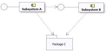
Subsystem and Package Dependencies in the Design Model
Subsystem Specification and Realization
Definition
The UML ([UML04]) states:
A number of UML standard stereotypes exist that apply to component, e.g. <<specification>> and <<realization>> to model components with distinct specification and realization definitions, where one specification may have multiple realizations.
A Component stereotyped by <<specification>> specifies a domain of objects without defining the physical implementation of those objects. It will only have provided and required interfaces, and is not intended to have any realizing classes and sub components as part of its definition.
A Component stereotyped by <<realization>> specifies a domain of objects and that also defines the physical implementation of those objects. For example, a Component stereotyped by <<realization>> will only have realizing classes and sub components that implement behavior specified by a separate <<specification>> Component.
The separation of specification and realization essentially allows for two separate descriptions of the subsystem. The specification serves as a contract that defines everything that a client needs to know to use the subsystem. The realization is the detailed internal design intended to guide the implementer. If you wish to support multiple realizations, create separate “realization” subsystems, and draw a realization from each realization subsystem to the specification subsystem.
When and how to use
If the internal state and behavior of the subsystem is relatively simple, it may be sufficient to specify the subsystem by its exposed interfaces, state diagrams to describe the behavior, and descriptive text.
For more complex internal state and behavior, analysis classes can be used to specify the subsystem at a high level of abstraction. For large systems of systems, the specification of a subsystem may also include use cases. See Developing Large-Scale Systems with the Rational Unified Process.
Providing a detailed specification separate from the realization tends to be most useful in the following situations:
- the subsystem realization’s internal state or behavior is complex - and the specification needs to be expressed as simply as possible in order for clients to use it effectively;
- the subsystem is a reusable “assembly component” intended for assembly into a number of systems (see Concepts: Component);
- the subsystem’s internals are expected to be developed by a separate organization;
- multiple implementations of the subsystem need to be created;
- the subsystem is expected to be replaced with another version that has significant internal changes without changes to the externally visible behavior.
Maintaining a separate specification takes effort, however - as one must ensure that the realization of the subsystem is compliant with the specification. The criteria for when and if to create separate specification and realization classes and collaborations should be defined in Artifact: Project Specific Guidelines.
Dependencies
A specification should define its dependencies. These are the interfaces and visible elements from other subsystems and packages that must be available in all compliant realizations of the subsystem.
A realization may have additional dependencies, introduced by the designer or implementer. For example, there may be an opportunity to use a utility component to simplify the implementation - but the use of this utility component is a detail that need not be exposed to clients. These additional dependencies should be captured on a separate diagram as part of the realization.
Relationship to Implementation
A fully detailed specification defines everything a client needs to use the subsystem. This means refining the exposed interfaces and any publicly visible elements so that they are one-to-one with code. Analysis classes introduced to specify the subsystem behavior should remain as high level abstractions, since they are intended to be independent of any subsystems realizations.
The realization elements of a subsystem should align closely to the code.
See Concepts: Mapping from Design to Code for some further discussion on this topic.
UML 1.x Representation
Modeling
Design subsystems may be modeled as either UML 2.0 components or UML 1.5 subsystems. These constructs provide almost equivalent modeling capabilities like modularity, encapsulation, and instances able to execute at run-time.
Some additional considerations about these modeling options are:
- UML 1.5 subsystems explicitly included the notion of “specification” and “realization” (defined above in the section titled [Subsystem Specification and Realization](#Subsystem Specification and Realization)). The UML 2.0 components support the notion of specification (in the form of one or more provided and required interfaces) and realization (internal implementation consisting of one or more classes and sub components that realize its behavior).
- UML 1.5 subsystems were also packages. UML 2.0 components have packaging capabilities, which means they may own and import a potentially large set of model elements.
However, by and large, these notations can be used interchangeably. Whether to represent Design Subsystems as UML 1.5 subsystems or UML 2.0 components is a decision that should be documented in the Project Specific Guidelines tailored for your process/project.
If your visual modeling tool supports UML 1.5 packages but not UML 1.5 subsystems, a package stereotyped as <<subsystem>> can be used to denote a subsystem.
Subsystem Dependency Restrictions
The same dependency restrictions and discussions mentioned in the section titled [Subsystem Dependency Restrictions](#Subsystem Dependency Restrictions) also apply for design subsystems being modeled as UML 1.5 subsystems.
An example of Subsystem and Package dependencies in UML 1.5 is shown below:
Subsystem and Package Dependencies in the Design Model
Subsystem Specification and Realization
The UML 1.5 stated:
The contents of a subsystem are divided into two subsets: 1) specification elements and 2) realization elements. The specification elements, together with the operations and receptions of the subsystem, are used for giving an abstract specification of the behavior offered by the realization elements. The collection of realization elements model the interior of the behavioral unit of the physical system.
The separation of specification and realization essentially allows for two separate descriptions of the subsystem. The specification serves as a contract that defines everything that a client needs to know to use the subsystem. The realization is the detailed internal design intended to guide the implementer.
One option for modeling specifications and realizations, if not directly supported by the modeling environment, is to place two packages, specification and realization, inside each subsystem.
One motivation for specifications is to support multiple realizations. This was not directly supported in the UML 1.x. If you wish to support multiple realizations using UML 1.5 subsystems, create separate “realization” subsystems, and draw a realization from each realization subsystem to the specification subsystem.
Basically, the same considerations for Specification and Realization that apply for UML 2.0, also apply here (see [When and How to Use](#When and How to Use), Dependencies, and [Relationship to Implementation](#Relationship to Implementation) for explanation).
Additional Information
Refer to Differences Between UML 1.x and UML 2.0for more information.
Guidelines: Development Case
Topics
- Explanation
- [Variable Elements in Software Engineering Processes](#Variable Elements in Software Engineering Processes)
- [Difficult Configurations](#Difficult Configurations)
- [Delegating Process Responsibility](#Delegating Process Responsibility)
- [Representing a Development Case Online](#Representing a Development Case Online)
Explanation
Expressed in terms of business modeling, the software development process is a business process, whereas the Rational Unified Process (RUP) product is a generic business process for object-oriented software engineering. A project-specific process is a static configuration of the RUP product; that is, it’s a business process for software engineering tailored to a specific project, product, and organization. The development case is a further refinement of this configured process, and focuses on what to do and how to do it.
A development case shows how the generic RUP applies to the context of your organization. This means that you modify the process and adapt the terminology.
A development case also provides an overview of the process to be followed, something understood by everyone on the project. For details, the development case should refer to the configured process and other guidelines or styleguides.
The process engineer is responsible for configuring the process, deciding how the development process will look, deploying the process Website, and “installing” the development case in the development organization (team, project or company), and teaching the developers how to use it.
Keep in mind that introducing a new development process, such as the RUP, into an organization is always a risk. You must continually weigh the advantages of a new technique against the cost of introducing the change. Consider introducing a change from both a managerial and a technical perspective.
Once a development case is set up by the process engineer, the project manager instantiates and executes it for the given project. This is often called process enactment.
As the process unfolds, lessons are learned during the process itself, which are used by the process engineer as feedback to improve the process.
Variable Elements in Software Engineering Processes
This section reviews the constituents of a process that are likely to be modified, customized, added or suppressed in a given development case.
- Disciplines A software project would rarely skip one of the disciplines, such as Analysis & Design, Implementation, and so on, completely. In exceptional cases, some disciplines, such as Requirements or Deployment, may have been executed by other organizations. However, it’s more likely that specific workflows within or across disciplines would be modified.
- Artifacts Projects are far more likely to differ by the artifacts that they have to produce, update, and deliver. At one extremity of the range, imagine a totally paperless project that electronically maintains only a small number of artifacts, is supported by tools such as spreadsheets, design tools, programming tools, and testing tools, and only delivers software and documentation electronically on disk, CD or over the World-Wide Web. At the other extreme, there are projects that must produce and maintain a much larger set of printed documents for contractual, regulatory or organizational reasons. In some cases, complete models can be omitted.
- Activities Activities are likely to vary for at least two reasons. Activities that use artifacts as input and produce, or update, artifacts as output are affected by the modification of these artifacts; in particular, if some artifact, or some element of information in an artifact, is no longer necessary, the corresponding steps maybe suppressed or significantly modified. Activities are also modified to introduce specific techniques, methods, and tools that pertain to the specific application domain or development expertise, such as design steps, programming languages, automatic code generation tools, measurement techniques, and so on.
At a more detailed level, other elements of the process can be modified, added or suppressed:
- Steps in activities
- Guidelines and guidance for activities
- Notations, such as using subsets of the UML or using stereotypes to address some specific need for some, or all, models
- Checkpoints for inspections and reviews
- Roles
- Tool support to automate some activities
- Terminology changes, for instance to adapt the process to the organizational context
In summary, the process engineer must make a wide range of decisions to create a well-adjusted development case out of the RUP. A development case may have to be adjusted to take advantage of certain well-established company practices and standards, such as documents, terminology, and so on.
Difficult Configurations
Certain configuration forms are difficult to implement and must be considered very carefully. For example:
- Change in process architecture Wide-ranging repackaging of the activities in another set of disciplines to match an existing process or organization may lead to a lot of effort for very little gain. Often, it’s more practical to simply establish a mapping to assess whether all aspects are covered by the RUP. Remember that the disciplines are not phases sequentially executed-they are containers for activities, and are executed again and again in each iteration, often concurrently within one iteration.
- Changes in terminology Although substituting one word for another may sound like a trivial exercise in word processing, such changes must be considered very carefully. In the domain of software engineering, organizations often use the same word with slightly different meanings, or different words that mean the same thing. Making isolated changes in the RUP may lead to a process that is very difficult to understand. One solution is to create a “translation table” for the terminology that translates between the RUP terminology and the organization’s terminology.
Examples of dangerous words are system, phase, role, activity, model, and document.
If the process results are captured in a language other than English, the terminology issues are more complex where you must translate the descriptions of artifacts, documents, reports, and possibly other parts of the RUP to this other language.
The extended RUP tool set provides automation in the area of RUP customization. Refer to the Rational Process Workbench(TM) product for more information om recommended strategies for tailoring the RUP.
Delegating Process Responsibility
The development case should not capture the entire process. In reality, a lot of responsibility, and decisions about the process, and the artifacts in particular, are delegated to members of the software development project. For example, if there is an experienced, good project manager, you may leave it to this individual to decide on what plans to produce and how to produce them. In the same way, many project managers aren’t concerned about how each team member designs his or her part of the system, as long as they deliver the expected functionality on time and within a reasonable level of quality.
One reason for having a process description at all is so several people can share information. If this is not the case, then the cost of maintaining the process description may be too high. Therefore, you may decide not to have, or maintain, the process description for one or several disciplines. This doesn’t mean that you don’t put effort into that particular discipline, nor does it mean that you don’t think it’s important. For example, you may employ an excellent test manager, provide all possible support, but leave it to that test manager to decide how to work and what artifacts to produce.
Representing a Development Case Online
A development case can be represented in several different ways:
- [One or several web pages](#One or several web pages)
- [A web site, with navigational tools](#A web site with navigational tools)
- [Integrated with RUP online](#Integrated with RUP online)
One or Several Web pages
It’s easiest to represent it as a Microsoft® Word® document, however, we recommend you represent the development case as one or several web pages with hyperlinks to the RUP configuration (project-specific or organizational) as needed. See Concepts: RUP Tailoring for more details.
A Web Site with Navigational Tools
There are great benefits to represent your project-specific process like the RUP Website. By always publishing your project’s process from the RUP Builder tool, you get all this for free. The resulting Website has the exact same functionality and look & feel as the classic RUP Website.
We recommend that you integrate the development case in your project web site, if you have one.
Integrated with RUP Online
You can also integrate the development case in the RUP online. This can be done using the Personal Process View or My RUP feature on a server based RUP Website. This approach will add a new view into the process configuration, manifested as a separate tab in the RUP Treebrowser. In this view you can add nodes for the pages that constitutes the development case. See Tool Mentor: Personalize the RUP Website using Personal Process View or My RUP, for detailed information on how to create Process Views inside the RUP Website.
Guidelines: Diagrams in the Business Analysis Model
Topics
Activity Diagrams
The activity diagram notation is further explained in Guidelines: Activity Diagram in the Business Use Case Model. This page exemplifies how the notation is applied to describe a business use case realization.
An activity diagram of a business use case realization explores the ordering of tasks or activities that accomplish business goals, and that satisfy commitments between external business actors and internal business workers. An activity may be a manual or automated task that completes a unit of work.
Activity diagrams help:
- Provide a rationale for and understanding of the introduction of information systems into the business.
- Establish objectives for system development projects to implement business transformation initiatives.
- Justify automation investment based on detailed business process metrics.
Compared to a sequence diagram, which could be perceived as having a similar purpose, an activity diagram with swimlanes and object flows focuses on how you divide responsibilities into classes, whereas the sequence diagram helps you understand how objects interact and in what sequence. Activity diagrams focus on the workflow, while sequence diagrams focus on handling business entities. Activity diagrams and sequence diagrams could be used as complementary techniques, where a sequence diagram shows what happens in an activity state.
Using Swimlanes
If you are using swimlanes and the swimlanes are coupled to classes (mainly business workers) in the business analysis model, you are using the activity diagram to document business use case realizations, rather than business use cases.
As an example, we show an activity diagram of the realization of the business use case Proposal process, which you can find described Guidelines: Business Use Case.
The realization of the business use case Proposal Process
The activity diagram provides the details of what happens within the business by examining people playing specific roles (the business workers) and the activities they perform. For application-development projects, these diagrams provide a detailed understanding of the business area that will be supported or impacted by the new application. They help establish connection points to the proposed new system, and these connection points give rise to system use cases.
Using Object Flows
In this context, object flows are used to show how business entities are created and used in a workflow. Object flows allow you to show inputs and outputs from activity states in an activity graph. There are two elements to the notation:
- The object flow state represents an object of a class that participates in the workflow the activity graph represents. The object may be the output of one activity and the input of many other activities.
- The object flow is a kind of control flow with an object flow state as input or an output.
The object flow symbol represents the existence of an object in a particular state, not just the object itself. The same object can be manipulated by a number of successive activities that change the object’s state. The object can then be displayed multiple times in an activity graph, with each appearance representing a different state during its life. The object’s state at each point may be placed in brackets and appended to the name of the class.
A generic sales process presented using object flows to show how an order changes it state while executing the workflow. See Guidelines: Activity Diagram in the Business Use Case Model
An object flow state may appear as the target of one object flow (transition) and the source of multiple object flows (transitions).
An activity diagram for the Proposal process, using object flows to show key business entities involved
Object flows can be compared to data flows within the workflow of a business use case. Unlike traditional data flows, however, object flows exist at a definite point within an activity graph.
Class Diagrams
Class diagrams show associations, aggregations and generalizations between business workers and business entities. The following kinds of class diagrams might be of interest:
- Inheritance hierarchies.
- Aggregates of business workers and business entities.
- How business workers and entities are related by means of associations.
Class diagrams show generic structures in the business domain model, but can also be part of the documentation of a business use case realization (see Guidelines: Business Use Case Realization) by showing it participating business workers and business entities.
A class diagram showing participating business workers and business entities in the business use case Individual Check-in.
Communication Diagrams
A communication diagram is semantically identical to a sequence diagram, but focuses on the objects, while the latter focuses on the interactions. A communication diagram should present the subset of objects relevant to the affected working sequence, including their links, messages, and message sequences.
Sequence Diagrams
A sequence diagram graphically depicts the details of the interaction among business workers, business actors, and how business entities are accessed, during the performance of a business use case. A sequence diagram briefly describes what the participating business workers do, and how the business entities are manipulated, in terms of activations, and how they communicate by sending messages to one another.
A sequence diagram of part of an Individual Check-in business use case.
The same information that can be found in a sequence diagram can be presented in a communication diagram instead.
Statechart Diagrams
Generally, you can use a state diagram to illustrate which states a business worker or a business entity can have - the events that cause a transition from one state to another; and the actions that result from a state change. A statechart diagram often simplifies the validation of the class design.
For each state that an object of the class can enter, a diagram shows the messages it can receive, the actions to be carried out, and the state the object of the class will be in thereafter.
The business entity Baggage described with a statechart diagram.
Guidelines: Equivalence Class Analysis
Topics
Introduction
Except for the most trivial of software applications, it is generally considered impossible to test all the input combinations logically feasible for a software system. Therefore, selecting a good subset that has the highest probability of finding the most errors, is a worthwhile and important task for testers to undertake.
Testing based on equivalence class analysis (synonyms: equivalence partitioning, domain analysis) is a form of black-box test analysis that attempts to reduce the total number of potential tests to a minimal set of tests that will uncover as many errors as possible [MYE79]. It is a method that partitions the set of inputs and outputs into a finite number of equivalence classes that enable the selection of a representative test value for each class. The test that results from the representative value for a class is said to be “equivalent” to the other values in the same class. If no errors were found in the test of the representative value, it is reasoned that all the other “equivalent” values wouldn’t identify any errors either.
The power of Equivalence Classes lies in their ability to guide the tester using a sampling strategy to reduce the combinatorial explosion of potentially necessary tests. The technique provides a logical bases by which a subset of the total conceivable number of tests can be selected. Here are some categories of problem areas for large numbers of tests that can be benefit from the consideration of equivalence classes:
- Combinations of independent variables
- Dependent variables based on hierarchical relationship
- Dependent variables based on temporal relationship
- Clustered relationships based on market exemplars
- Complex relationships that can be modeled
Strategies
There are different strategies and techniques that can be used in equivalence partition testing. Here are some examples:
Equivalence Class Partition
Equivalence partition theory as proposed by Glenford Myers [MYE79]. attempts to reduce the total number of test cases necessary by partitioning the input conditions into a finite number of equivalence classes. Two types of equivalence classes are classified: the set of valid inputs to the program is regarded as the valid equivalence class, and all other inputs are included in the invalid equivalence class.
Here are a set of guidelines to identify equivalence classes:
- If an input condition specifies a range of values (such as, program “accepts values from 10 to 100”), then one valid equivalence class (from 10 to 100) and two invalid equivalence classes are identified (less than 10 and greater than 100).
- If an input condition specifies a set of values (such as, “cloth can be many colors: RED, WHITE, BLACK, GREEN, BROWN “), then one valid equivalence class (the valid values) and one invalid equivalence class (all the other invalid values) are identified. Each value of the valid equivalence class should be handled distinctly.
- If the input condition is specified as a “must be” situation (such as, “the input string must be upper case”), then one valid equivalence class (uppercase characters) and one invalid equivalence (all the other input except uppercase characters) class are identified.
- Everything finished “long” before the task is done is an equivalence class. Everything done within some short time interval before the program is finished is another class. Everything done just before program starts another operation is another class.
- If a program is specified to work with memory size from 64M to 256M. Then this size range is an equivalence class. Any other memory size, which is greater than 256M or less than 64M, can be accepted.
- The partition of output event lies in the inputs of the program. Even though different input equivalence classes could have same type of output event, you should still treat the input equivalence classes distinctly.
Boundary Value Analysis
In each of the equivalence classes, the boundary conditions are considered to have a higher rate of success identifying resulting failures than non-boundary conditions. Boundary conditions are the values at, immediately above or below the boundary or “edges” of each equivalence classes.
Tests that result from boundary conditions make use of values at the minimum (min), just above minimum (min+), just below the maximum (max-), and the maximum (max) of the range that needs be tested. When testing boundary values, testers choose a few test cases for each equivalence class. For the relatively small sample of tests the likelihood of failure discovery is high. The Tester is given some relief from the burden of testing a huge population of cases in an equivalent class of values that are unlikely to produce large differences in testing results.
Some recommendations when choosing boundary values:
- For a floating variable, if the valid condition of it is from
-1.0to1.0, test-1.0,1.0,-1.001and1.001. - For an integer, if the valid range of input is
10to100, test9,10,100,101. - If a program expects an uppercase letter, test the boundary A and Z. Test
@and[too, because in ASCII code,@is just below A and[is just beyond the Z. - If the input or output of a program is an ordered set, pay attention on the first and the last element of the set.
- If the sum of the inputs must be a specific number (
n), test the program where the sum isn-1,n, orn+1. - If the program accepts a list, test values in the list. All the other values are invalid.
- When reading from or writing to a file, check the first and last characters in the file.
- The smallest denomination of money is one cent or equivalent. If the program
accepts a specific range, from a to b, test a
-0.01and b+0.01. - For a variable with multiple ranges, each range is an equivalence class. If the sub-ranges are not overlapped, test the values on the boundaries, beyond the upper boundary, and below the lower boundary.
Special Values
After attempting the two previous boundary analysis strategies, an experienced tester will observe the program inputs to discovery any “special value” cases, which are again potentially rich sources for uncovering software failures. Here are some examples:
- For an integer type, zero should always be tested if it is in the valid equivalence class.
- When testing time (hour, minute and second), 59 and 0 should always be tested as the upper and lower bound for each field, no matter what constraint the input variable has. Thus, except the boundary values of the input, -1, 0, 59 and 60 should always be test cases.
- When testing date (year, month and day), several test cases, such as number of days in a specific month, the number of days in February in leap year, the number of days in the non-leap year, should be involved.
“Category-Partition” Method
Ostrand and Balcer [16] developed a partition method that helps testers to analyze the system specification, write test scripts, and manage them. Different from common strategies that mostly focuses on the code, their method is based on the specification and design information too.
The main benefit of this method is its ability to expose errors before the code has been written because the input source is the specification and the tests result from the analysis of that specification. Faults in the specifications will be discovered early, often well before they are implemented in code.
The strategy for the “category-partition” method follows:
-
Analyze the specification: decompose the system functionality into functional units, which can be tested independently both by specification and implementation. From there;
- Identify the parameters and the environment conditions that will influence the function’s execution. Parameters are the inputs of the function unit. Environment conditions are the system states, which will effect the execution of the function unit.
- Identify the characteristics of the parameters and the environment conditions.
- Classify the characteristics into categories, which effect the behavior of the system.Ambiguous, contradictory, and missing descriptions of behavior will be discovered in this stage.
-
Partition the categories into choices: Choices are the different possible situations that might occur and not be expected. They represent the same type of information in a category.
-
Determine the relations and the constraints among choices. The choices in different categories influence with each other, which also have an influence of building the test suite. Constraints are added to eliminate the contradiction of between choices of different parameters and environments.
-
Design test cases according to the categories, choices and constraint information. If a choice causes an error, don’t combine it with other choices to create the test case. If a choice can be “adequately” tested by one single test, it is either the representative of the choice or a special value.
Further Reading and References
- Glenford J. Myers, The Art of Software Testing, John Wiley & Sons, Inc., New York, 1979.
- White L. J. and Cohen E. I., A domain strategy for computer program testing, IEEE Transaction on Software Engineering, Vol. SE-6, No. 3, 1980.
- Lori A. Clarke, Johnhette Hassell, and Debra J Richardson, A Close Look at Domain Testing, IEEE Transaction on Software Engineering, 8-4, 1992.
- Steven J. Zeil, Faten H. Afifi and Lee J. White, Detection of Linear Detection via Domain Testing, ACM Transaction on Software Engineering and Methodology, 1-4, 1992.
- BingHiang Jeng, Elaine J. Weyuker, A Simplified Domain-Testing Strategy, ACM Transaction on Software Engineering and Methodology, 3-3, 1994.
- Paul C. Jorgensen, Software Testing - A Craftsman’s Approach, CRC Press LLC, 1995.
- Martin R. Woodward and Zuhoor A. Al-khanjari, Testability, fault, and the domain-to-range ratio: An eternal triangle, ACM Press New York, NY, 2000.
- Dick Hamlet, On subdomains: Testing, profiles, and components, SIGSOFT: ACM Special Interest Group on Software Engineering, 71-16, 2000.
- Cem Kaner, James Bach, and Bret Pettichord, Lessons learned in Software Testing, John Wiley & Sons, Inc., New York, 2002.
- Andy Podgurski and Charles Yang, Partition Testing, Stratified Sampling, and Cluster Analysis, SIGSOFT: ACM Special Interest Group on Software Engineering, 18-5, 1993.
- Debra J. Richardson and Lori A. Clarke, A partition analysis method to increase program reliability, SIGSOFT: ACM Special Interest Group on Software Engineering, 1981.
- Lori A. Clarke, Johnette Hassell, and Debra J Richardson, A system to generate test data and symbolically execute programs, IEEE Transaction on Software Engineering, SE-2, 1976.
- Boris Beizer, Black-Box Testing - Techniques for Functional testing of Software and System, John Wiley & Sons, Inc., 1995.
- Steven J. Zeil, Faten H. Afifi and Lee J. White, Testing for Liner Errors in Nonlinear computer programs, ACM Transaction on Software Engineering and Methodology, 1-4, 1992.
- William E. Howden, Functional Program Testing, IEEE Transactions on Software Engineering, Vol. SE-6, No. 2, 1980.
- Thomas J. Ostrand and Marc J. Balcer, The Category-Partition method for specifying and generating functional tests, Communications of ACM 31, 1988.
- Cem Kaner, Jack Falk and Hung Quoc Nguyen, Testing Computer Software, John Wiley & Sons, Inc., 1999.
Guidelines: Estimating Effort Using the Wide-Band Delphi Technique
Contributed to RUP by Karl Wiegers (www.processimpact.com), with permission from Software Development Magazine. Further edited by Rational Software Corporation.
Topics
- Introduction
- [Applying Wideband Delphi](#Applying Wideband Delphi)
- Planning
- [The Kickoff](#The Kickoff)
- [Individual Preparation](#Individual Preparation)
- [Estimation Meeting](#Estimation Meeting)
- [Assembling Tasks](#Assembling Tasks)
- [Review Results](#Review Results)
- [Completing the Estimation](#Completing the Estimation)
- [Doing It Again (Iterating)](#Doing It Again)
- [Wideband Delphi Evaluated](#Wideband Delphi Evaluated)
Introduction
This guideline describes a technique that can be used to estimate software development effort. The Wideband Delphi estimation method can be summarized as follows:
- Select a team of experts, and provide each with a description of the problem to be estimated.
- Ask each expert to provide an estimate (often anonymously) of the effort, including a breakdown of the problem into a list of tasks, and an effort estimate for each task.
- The experts then collaborate, revising their estimates iteratively, until a consensus has been reached.
Using the Wideband Delphi method provides several advantages over obtaining an estimate from a single individual. First, it helps build a complete task list or work breakdown structure for major activities, because each participant will think of tasks. The consensus approach helps eliminate bias in estimates produced by self-proclaimed experts, inexperienced estimators or influential individuals who have hidden agendas or divergent objectives. People are generally more committed to estimates they help produce than to those generated by others. No participant in an estimation activity knows the “right” answer, and creating multiple estimates acknowledges this uncertainty. Finally, users of the Delphi approach recognize the value of iteration on any complex activity.
Applying Wideband Delphi
Wideband Delphi can be used to estimate virtually anything-the number of labor months needed to implement a specific subsystem, the lines of code or number of classes in an entire product, or the gallons of paint needed to redecorate Bill Gates’ house, or the effort it would take a particular organization to achieve level two of the Capability Maturity Model.
The Delphi method helps you develop a detailed work breakdown structure, which provides the foundation for bottom-up effort and schedule or size estimation. The starting point for a Delphi session could be a Vision document, a more detailed Requirements specification of the problem being estimated or an initial high-level architecture description, or a project schedule. The outputs are a more detailed project activity list; a list of associated quality, process-related and overhead activities; estimation assumptions; and a set of activities and overall project estimates, one from each participant.
Figure 1 illustrates the process flow for a Wideband Delphi session. The problem being estimated is defined and the participants selected during planning. The kickoff meeting gets all estimators focused on the problem. Each participant then individually prepares his or her initial activity lists and estimates. They bring these items to the estimation meeting, during which several estimating cycles lead to a more comprehensive activity list and a revised set of estimates. The moderator or project manager then consolidates the assorted estimation information offline, and the team reviews the estimation results. When some predetermined exit criteria are satisfied, the session is completed. The resulting range of estimates is likely to be a more realistic predictor of the future than any single estimate. Let’s look at each of these process steps in turn.
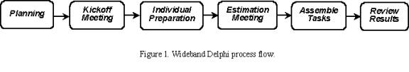
When planning a Wideband Delphi session, the problem is defined and the participants selected. The kickoff meeting gets all estimators focused on the problem. Each participant then individually prepares initial activity lists and estimates. During the estimation meeting, several cycles lead to a more comprehensive activity list and a revised set of estimates. The information is then consolidated offline, and the team reviews the estimation results. When the exit criteria are satisfied, the session is completed.
Planning
A Wideband Delphi session begins with defining and scoping the problem: vision, use case model, existing system, preliminary architecture. Large problems are broken down into manageable portions that can be estimated more accurately, perhaps by different teams. The person who initiated the estimation activity assembles a problem specification that will give the participants enough information to produce credible, informed estimates.
The estimation participants include a moderator, who plans and coordinates the activity, the project manager and two to four other estimators. The moderator should be informed enough to participate as an estimator but acts as an impartial facilitator who won’t skew the results with his or her own biases or insights. The participants are selected because they understand the problem or project and associated estimation issues.
The Kickoff
An initial kickoff meeting of up to an hour gets all participants up to speed on the estimation problem. The moderator explains Wideband Delphi to team members who are unfamiliar with it and supplies the other estimators with the problem specification and any assumptions or project constraints. The moderator strives to give the estimators enough information to do a good job without unduly influencing their estimates.
The team reviews the estimation objectives and discusses the problem and any estimation issues. The participants agree on the estimation units they will use, such as weeks, labor hours, dollars or lines of code. If the moderator concludes that all team members are sufficiently knowledgeable to contribute to the estimation activity, the group is ready to roll. Otherwise, the participants may need to be briefed more fully on the problem they’re estimating, or possibly replaced by others who can generate more accurate estimates.
To determine whether you’re ready to proceed with the Wideband Delphi session, check your entry criteria-that is, the prerequisites that must be satisfied for you to proceed with subsequent process steps. Before you dive into the estimation exercise, ensure that the following conditions are satisfied:
- Appropriate team members have been selected.
- The kickoff meeting has been held.
- The participants have agreed on the estimation goal and units.
- The project manager can participate in the session.
- The estimators have the information they need to participate effectively.
Individual Preparation
Let’s assume that you wish to estimate the total amount of work effort (typically expressed in labor hours) needed to complete a certain project. The estimation process begins with each participant independently developing an initial list of the tasks that will have to be completed to reach the stated project goal, using a form like that shown in Figure 2. Each participant then estimates the effort each task will consume. Break each task down into activities that are small enough to estimate accurately. State the activities clearly, because someone will have to merge all of the participant activity lists into a single composite list. Total the estimates you produce for each project task, in the agreed-upon units, to generate your initial overall estimate.
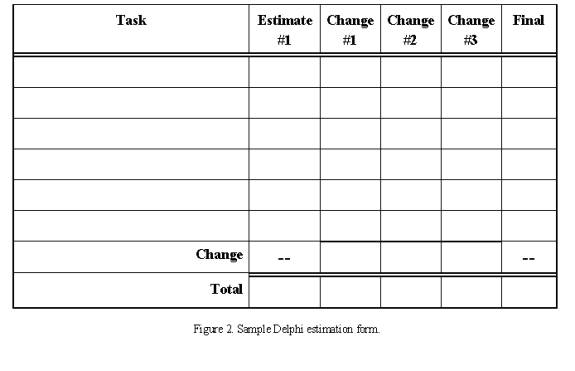
The estimation process begins with each participant independently using this form to develop an initial list of the tasks that will have to be completed to reach the stated project goal.
Your estimate should have no relationship to the answer you think the project manager or other stakeholders want to hear. There’s a good chance the estimate will fall outside the acceptable project bounds of schedule, effort or cost, a situation that demands negotiation and might lead to scope reduction, schedule extension or resource adjustments. But don’t let outside pressure sway your best projection of how the project will play out.
In addition to identifying the project tasks, separately record any tasks for related or supporting activities. Do not forgot to list tasks dealing with management, configuration management and process-related activities on the first cycle. Be sure to include rework activities following testing or inspection activities. Reworking to correct defects is a fact of life, so you should plan for it. If you’re estimating a schedule, also think of any overhead activities that aren’t specific to the project that you might have to build into your planning. These include meetings, vacation, training, other project assignments and myriad other things that suck time out of your day.
Since radically different assumptions can lead to wide estimate variations, record any assumptions you made while preparing your estimates. For example, if you assumed that you will purchase a specific component library or reuse one from a previous project, write that down. Another estimator might assume that the project will develop that library, which will lead to a mismatch between your two overall estimates.
Keep the following estimation guidelines in mind:
- Assume one person (you) will perform all tasks.
- Assume all tasks will be performed sequentially; don’t worry about sequencing and predecessor tasks at this time.
- Assume that you can devote uninterrupted effort to each task (this may seem absurdly optimistic, but it simplifies the estimation process).
- In units of calendar time, list any known waiting times you expect to encounter between tasks. This will help you translate effort estimates into schedule estimates later on.
Estimation Meeting
The moderator begins the estimation meeting by collecting the participants’ individual estimates and creating a chart such as Figure 3. Each participant’s total project estimate is shown as an X on the “Round 1” line. Each estimator can see where his or her initial value fits along the spectrum. The initial estimates probably will cover a frighteningly large range. Just imagine the different conclusions you might have collected had you asked just one of the participants for his or her estimate and used that to plan the project.
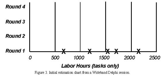
The moderator begins the estimation meeting by collecting and charting the participants’ individual estimates. Each participant’s total project estimate is shown as an X on the “Round 1” line. The initial estimates probably will cover a frighteningly large range.
In some organization, the moderator does not identify who created each estimate; they feel this anonymity is an important aspect of the Delphi technique. Anonymity prevents an outspoken colleague from intimidating the other participants into seeing things his or her way. It also means team members are less likely to defer to the most respected participant’s judgment when their own analyses lead to different conclusions. But this is not a must.
Each estimator reads his initial task list, identifying any assumptions made and raising any questions or issues, without revealing which estimate was his. Each participant will have listed different tasks that need to be performed. Combining these individual task lists leads to a more complete list than any single estimator is likely to produce. This approach will work for up to several dozen individual tasks. If you have more tasks than that, they might be too detailed. You may want to break the problem into several subproblems and estimate them individually.
During this initial discussion, the team members also talk about their assumptions, estimation issues and questions they have about the problem. As a result, the team will begin to converge on a shared set of assumptions and a common task list. Retain this final task list to use as a starting point the next time you must estimate a similar project.
After this initial discussion, all participants modify their estimates concurrently (and silently) in the meeting room. They might revise their task lists based on the information shared during the discussion, and they’ll adjust individual task estimates based on their new understanding of the task scope or changed assumptions. All estimators can add new tasks to their forms and note any changes they wish to make to their initial task estimates. The net change for all tasks equals the change in that participant’s overall project estimate.
The moderator collects the revised overall estimates and plots them on the same chart, on the “Round 2” line. I’ve done this on a whiteboard for easy visibility. As Figure 4 illustrates, the second round might lead to a narrower distribution of estimates centered around a higher mean than the mean of the Round 1 values. Additional rounds should further narrow the distribution. The cycle of revising the task list, discussing issues and assumptions and preparing new estimates continues until:
- you have completed four rounds;
- the estimates have converged to an acceptably narrow range (defined in advance);
- the allotted estimation meeting time (typically two hours) is over; or
- all participants are unwilling to alter their latest estimates.
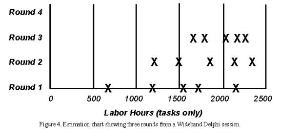
After discussion of the initial estimates, all participants modify their estimates. The moderator collects the revised overall estimates and plots them on the same chart, on the “Round 2” line. These later rounds might lead to a narrower distribution of estimates centered around a higher mean than the mean of the Round 1 values.
The moderator keeps the group on track, time-boxing discussions to 15 or 20 minutes to avoid endless rambling. The moderator should follow effective meeting facilitation practices, such as starting and ending on time, encouraging all participants to contribute and maintaining an impartial and non-judgmental environment. While preserving the anonymity of individual estimates is important for the first couple of rounds, the team members might agree at some point to put all their cards on the table and reach closure through an open discussion. This gives them a chance to discuss tasks for which their estimates vary substantially. Otherwise, though, the moderator should not identify the individual who produced each final estimate until the session is completed.
Assembling Tasks
The work isn’t done when the estimation meeting concludes. Either the moderator or the project manager assembles the project tasks and their individual estimates into a single master task list. This person also merges the individual lists of assumptions, quality- and process-related activities, overhead tasks and wait times.
The merging process involves removing duplicate tasks and reaching some reasonable resolution of different estimates for individual tasks. “Reasonable” doesn’t mean replacing the team’s estimates with values the project manager prefers. Large estimate differences for apparently similar tasks might indicate that estimators interpreted that activity in different ways. For example, two people might both have an activity called “implement a class.” However, one estimator might have included unit testing and code review in the task, while the other meant just the coding effort. All estimators should define their activities clearly to minimize confusion during this merging step. The merging step should retain the estimate range for each task, but if one estimator’s task estimate was wildly different from that of the other estimators, understand it and then perhaps discard or modify it.
Review Results
In the final step, the estimation team reviews the summarized results and reaches agreement on the final outcome. The project manager provides the other estimators with the overall task list, individual estimates, cumulative estimates, assumption list and any other information. Bring the team back together for a 30- to 60-minute review meeting to bring closure to the estimation activity. This meeting also provides an opportunity for the team to contemplate this execution of the Wideband Delphi process and suggest ways it can be improved for future applications.
The participants should make sure the final task list is as complete as possible. They might have thought of additional tasks since the estimation meeting, which could be added to the task list now. Check to see whether tasks that had wildly different individual estimates have been merged in a sensible way. The ultimate objective is to produce an estimate range that allows the project manager and other key stakeholders to proceed with project planning and execution at an acceptable confidence level.
Completing the Estimation
The estimation process is completed when specified exit criteria are satisfied, at which point you can declare victory and move on with your life. Typical Wideband Delphi exit criteria are that:
The overall task list has been assembled.
You have a summarized list of estimating assumptions.
The estimators have reached consensus on how their individual estimates were synthesized into a single set with an acceptable range.
Now you must decide what to do with the data. You could simply average the final estimates to come up with a single point estimate, which is what the person who requested the estimate probably wants to hear. However, a simple average is likely to be too low, and there’s merit in retaining the estimate range. Estimates are predictions of the future, and the range reflects the inherent uncertainty of gazing into the crystal ball. You might present three numbers: the average of the estimates as the planned case, the minimum value as the best case and the maximum as the worst case. Or you could present the average value as the nominal expected outcome, plus the maximum-minus-the-average value, and minus the average-minus-the-minimum value.
Each estimate has a certain probability of coming true, so a set of estimates forms a probability distribution. In Chapter 6 of A Discipline for Software Engineering (Addison-Wesley, 1995), Watts Humphrey describes a mathematically precise way to combine multiple estimates and their uncertainties to generate an overall estimate with upper and lower prediction intervals. Another sophisticated approach is to perform a Monte Carlo simulation to generate a probability distribution of possible estimate outcomes based on the final estimate values.
While the results of a Delphi session might not be what the movers and shakers want to hear, they can decide whether they want to plan their project at a 10 percent confidence level, a 90 percent confidence level or somewhere in-between. Be sure to compare the actual project results to your estimates to improve your future estimating accuracy.
Doing It Again (Iterating)
One nice aspect of this method is that after an initial and rather rough estimate done for example during inception, the estimates can be refined at each phase (or even at each iteration). The process can be faster if the same estimators are available, starting where they left at the previous estimation cycle. More information about the problem is available, some assumptions have been modified, an architecture is in place to help break down the effort.
The new estimate may have a narrower range, but is not necessarily within the range of the previous one: it may be higher, or smaller. If higher, there is a clear risk signal to the project manager, risk that must be tackled at once.
Wideband Delphi Evaluated
No estimation method is perfect; if it were, it would be called prediction, not estimation. However, the Wideband Delphi technique incorporates some solid estimating principles. The team approach acknowledges the value of combining multiple expert perspectives. The range of estimates produced reflects the variability intrinsic to the estimation process.
Although it takes time and requires a panel of experienced estimators, Wideband Delphi removes some of the politics from estimation and filters out extreme initial values.
Guidelines: Extend-Relationship
Topics
- Explanation
- [Executing the extension](#Executing the Extension)
- [Documenting the extend-relationship](#Documenting the Extend-Relationship)
- [Example of use](#Example of Use)
Explanation
The extend-relationship connects an extension use case to a base use case. You define where in the base to insert the extension by referring to extension points in the base use case (see Guidelines: Use Case, the discussion on extension points). The extension use case is often abstract, but does not have to be.
You can use the extensions for several purposes:
- To show that a part of a use case is optional, or potentially optional, system behavior. In this way, you separate optional behavior from mandatory behavior in your model.
- To show that a subflow is executed only under certain (sometimes exceptional) conditions, such as triggering an alarm.
- To show that there may be a set of behavior segments of which one or several may be inserted at an extension point in a base use case. The behavior segments that are inserted (and the order in which they are inserted) will depend on the interaction with the actors during the execution of the base use case.
The extension is conditional, which means its execution is dependent on what has happened while executing the base use case. The base use case does not control the conditions for the execution of the extension - the conditions are described within the extend-relationship. The extension use case may access and modify attributes of the base use case. The base use case, however, cannot see the extensions and may not access their attributes.
The base use case is implicitly modified by the extensions. You can also say that the base use case defines a modular framework into which extensions can be added, but the base does not have any visibility of the specific extensions.
The base use case should be complete in and of itself, meaning that it should be understandable and meaningful without any references to the extensions. However, the base use case is not independent of the extensions, since it cannot be executed without the possibility of following the extensions.
Example:
The use cases Place Conference Call and Show Caller Identity are both extensions to the base use case Place Call.
In a phone system, the primary service provided to the users is represented by the use case Place Call. Examples of optional services are:
- To be able to add a third party to a call (Place Conference Call).
- To allow the receiving party to see the identity of the caller (Show Caller Identity).
We can represent the behaviors needed for these optional services as extension use cases to the base use case Place Call. This is a correct use of the extend-relationship: since Place Call is meaningful in itself, you do not need to read the descriptions of the extension use cases to understand the primary purpose of the base use case, and the extensions use cases have optional character.
If both the base use case and the “base plus extension” use case must be explicitly instantiable, or if you want the addition to modify behavior in the base use case, you should use use-case-generalization instead (see Guidelines: Use-Case-Generalization).
The extension use case can consist of one or more insertion segments, each of which may have alternative paths built into it. These insertion segments incrementally modify the behavior of the base use case. Each insertion segment in an extension use case can be inserted at a separate location in the base use case. This means that the extend-relationship has a list of references to extension points, equal in number to the number of insertion segments in the extension use case. Each extension point must be defined in the base use case.
One base use case consist of several extend-relationships, which means a use case instance can follow more than one extension during its lifetime. One extension use case may extend into several base use cases, but this does not imply any dependency between the base use cases. There may even be multiple extend-relationships between the same extension use case and base use case, provided the extension is inserted at different locations in the base. This means the different extend-relationships need to refer to different extension points in the base use case. An extension use case may itself be the base in an extend-, include-, or generalization-relationship. For example, this means extension use cases can extend other extension use cases in a nested manner.
Executing the Extension
When a use-case instance performing the base use case reaches a location in the base use case where an extension point has been defined, the condition on the corresponding extend-relationship is evaluated. If the condition is true or if it is absent, the use-case instance will follow the extension (or the insertion segment within it that corresponds to the extension point). If the condition of the extend-relationship is false, the extension is not executed.
The extension use case may, just like any use case, have a basic flow of events and alternative flows of events (see Guidelines: Use Case, the discussion on structure of flow of events). Which exact path the use-case instance will take through the extension depends on what has happened before in the execution (the state of the use-case instance) and also what happens in interaction with actors as the extension is executed. Once the use-case instance has performed the extension, the use-case instance resumes executing the base use case at the point where it left off.
A use-case instance following a base use case and its extension.
An extension use case can have more than one insertion segment, each related to its own extension point in the base use case. If this is the case, the use-case instance will resume the base use case and continue to the next extension point specified in the extend-relationship. At that point it will execute the next insertion segment of the extension use case. This is repeated until the last insertion segment has been executed. Note that the condition for the extend-relationship is checked at the first extension point only - if the condition is true, the use-case instance must perform all insertion segments.
A use-case instance following a base use case and an extension use case, the latter with two insertion segments.
The multiplicity of the extend-relationship will constrain the number of repetitions of the entire extension that may occur. Note that it is the entire extension that is repeated (and limited by the multiplicity), not just one insertion segment.
Documenting the Extend-Relationship
Describe the condition of the extension in terms of attributes of the base use case. You can also choose to omit the condition, in which case the extension will always be executed.
Each extend-relationship has a list of references to extension points (one or more) in the base use case. The extension points are referenced by name. If the extension use case has multiple insertion segments, you need to specify which segment corresponds to which extension point. You also need to specify which steps or subflows of the extension use case constitute each insertion segment.
Example:
In a phone system, the use case Place Call can be extended by the abstract use case Show Caller Identity. This is an optional service, often referred to as “Caller ID”, that may or may not have been requested by the receiving party. A description of the extend-relationship from Show Caller Identity to Place Call could look as follows:
Condition: Receiving party must have ordered the service “Caller ID”.
Extension Point(s): Show Identity - insert the whole Show Caller Identity use case.
You may give the extend-relationship a multiplicity, if it is omitted the multiplicity is assumed to be one.
Example of Use
Consider the following simple phone system:
The abstract use case Place Conference Call is an extension to the use case Place Call.
In this model, a simple representation of our familiar phone system, basic call service is described in the use case Place Call. A step-by-step outline to the basic flow of events would look like this:
- The Caller lifts receiver.
- The system presents dial-tone.
- The Caller dials a digit.
- The System turns off the dial-tone.
- The Caller enters the remainder of the number.
- The system analyzes digits, determines network address of the Receiving Party.
- The system analyzes the digits, determining the location in the network where the Receiving Party exists.
- The system then determines whether a virtual circuit can be established to the Receiving Party.
- If a virtual circuit can be established, the System rings the Receiving Party’s phone and presents the ringing tone on the Caller’s phone.
- When the Receiving Party answers the phone, the system disables the ringing tone on the Caller’s phone, stops ringing the Receiving Party’s phone and completes the virtual circuit.
- The system starts a billing record, recording the start time for the call, the end points of the call, and the Caller’s customer information.
- The call continues for some length of time. When either the Caller or the Receiving Party disconnects from the call, the system records the end time for the call, and frees all resources required to support the virtual circuit. The use case then ends.
To add functionality to this system that would allow the caller or receiving party to connect a third party to the call (often called “conference call”), we need to add behavior to the flow of events. One alternative, and the first one we should consider, is to put the differences directly into Place Call. We could model these differences using alternative flows of events, as described in Guidelines: Use Case. This solution works for most simple additions, where the added functionality will not confuse or obscure the original meaning of the use case. The other alternative is to separate the differences into an abstract extension use case called Place Conference Call which extends the base use case.
The Place Call use case would have the following addition:
Extension points: Conference Call occurs after step 11.
The extension use case, Place Conference Call, could then be described as:
Place Conference Call Use CaseThis use case extends Place Call. It is inserted at extension point Conference Call. Basic Flow:
- Caller depresses the hang-up, link, or flash button.
- The system generates 3 short beeps to acknowledge.
3..12.<these steps are identical to steps 3..12 from the base use case> 13. Caller is reconnected to the receiving party from the Place Call use case.
The commonality of steps 3..12 with the base use case is undesirable. One way to solve this is to factor out the common part as an inclusion use case (see Guidelines: Include-Relationship).
Guidelines: Extend-Relationship in the Business Use-Case Model
Topics
Explanation
Extend-relationships optionally, or conditionally, add a flow to a business use case that is already complete in itself. For example, Special Baggage Handling is inserted into Individual Check-in in cases where the passenger must go to the special baggage counter.
For comparison, see also Guideline: Extend-Relationship in the system use-case model.
Use
Once you have outlined the workflow of a business use case, you may find behavior that is conditional or optional. If this part of the behavior is substantial you will probably want to describe it separately. The most natural approach is to describe it in a separate subsection of the workflow documentation, but an alternative is describing it in a separate business use case that is an extension to the original business use case.
The latter approach is especially interesting if the extracted part is also substantial, logically connected, naturally delimited, and if you want to keep the original business use case simple. Or if the same optional extension is relevant to several business use cases.
An instance of a business use case that is optionally extended by another use case first follows the description of the base use case and then, if some condition is fulfilled, turns to follow the extending business use case?s description instead. When it reaches the end of the extension use case, it returns to following the description of the base.
The workflow of the Special Baggage Handling use case is inserted into the Individual Check-in use case with an extend-relationship.
The business use cases being extended have to be meaningful and complete in themselves, even if the workflow of the added business use case is not executed. Most extending business use cases cannot be executed on their own.
For example, use an extend-relationship to augment a business use case to:
- Model conditional, or optional behavior in a business use case by describing the workflows in different use cases, where conditional or optional behavior is distinguished from mandatory behavior.
- Model a complex workflow that seldom occurs.
- Model a separate subflow that is only run under certain conditions.
- Model several different business use cases that can be inserted at a certain point (the order being governed by the business actor).
Guidelines: Forward-Engineering Relational Databases
Topics
- Introduction
- [Transforming
Design Model Elements to Data Model Elements](#Transform Design Model Elements to Data Model Elements)
- [Mapping Persistent Classes to Tables](#Mapping Persistent Classes to Tables)
- [Persistent Attributes and Keys](#Persistent Attributes and Keys)
- [Mapping Associations Between Persistent Objects to the Data Model](#Mapping Associations between Persistent Objects to the Data Model)
- [Mapping Aggregation Associations to the Data Model](#Mapping Aggregation Associations to the Data Model)
- [Modeling Generalization Relationships in the Data Model](#Modeling Inheritance)
- [Modeling Many-to-Many Associations in the Data Model](#Modeling Many-to-Many Associations)
- [Refining the Data Model](#Refine the Data Model)
- [Forward-Engineering the Data Model](#Forward-Engineering the Data Model)
Introduction
This guideline describes methods for mapping persistent design classes in the Design Model into tables in the Data Model.
Transforming Design Model Elements to Data Model Elements
Persistent classes from the design model can be transformed to tables in the Data Model. The table below shows a summary of the mapping between Design Model elements and Data Model elements.
| Design Model Element | Corresponding Data Model Element |
|---|---|
| Class | Table |
| Attribute | Column |
| Association | Non-Identifying Relationship |
| Association Class | Intersection Table |
| Composite Aggregation | Identifying Relationship |
| Many-to-Many Association | Intersection Table |
| Multiplicity | Cardinality |
| Qualified Association | Intersection Table |
| Generalization (Inheritance) | Separate Table |
Mapping Persistent Classes to Tables
The persistent classes in the Design Model represent the information that the system must store. Conceptually, these classes might resemble a relational design. (For example, the classes in the Design Model might be reflected in some fashion as entities in the relational schema.) As a project moves from elaboration into construction, however, the goals of the Design Model and the Relational Data Model diverge. This divergence is caused because the objective of relational database development is to normalize data, whereas the goal of the Design Model is to encapsulate increasingly complex behavior. The divergence of these two perspectives-data and behavior-leads to the need for mapping between related elements in the two models.
In a relational database written in third normal form, every row in the tables-every “tuple”-is regarded as an object. A column in a table is equivalent to a persistent attribute of a class. (Keep in mind that a persistent class might have transient attributes.) Therefore, in the simple case in which there are no associations to other classes, the mapping between the two worlds is simple. The datatype of the attribute corresponds to one of the allowable datatypes for columns.
Example
The folllowing class Customer:
when modeled in the RDBMS would translate to a table called Customer, with the columns Customer_ID, Name, and Address.
An instance of this table can be visualized as:
Persistent Attributes and Keys
For each persistent attribute, questions must be asked to elicit additional information that will be used to appropriately model the persistent object in a relational Data Model. For example:
- Can this persistent attribute serve as a key or part of a key? Example: “Attribute X, together with attribute Z, uniquely identifies the object.” In the Customer table, the Customer_ID represents a primary key.
- What are the minimum and maximum values for the attribute?
- Will it be possible to search using this attribute as a key? It might, for instance, be part of a filter in a Select statement such as “It is common to search for all instances where Y > 1000.”
- Does the attribute have a description such as “attribute X is the number of retransmissions per 100 000 transmitted characters”?
- Does the attribute have possible numerical values and desired conversions between different numerical values?
- Who is allowed to update the attribute? Example: “T may only be changed by people in authority class nn.”
- Who is allowed to read the attribute? Examples: “P may be read by people in authority classes yy and zz” or ““P is included in views Vi and Vj.”
- Is there adequate information about volumes and frequencies? Examples: “There are up to 50 000 occurrences of A” or “On average 2000 As are changed per day.”
- Is the attribute unique? Example: Only one person can have the same driver’s license number.
Mapping Associations Between Persistent Objects to the Data Model
Associations between two persistent objects are realized as foreign keys to the associated objects. A foreign keyis a column in one table that contains the primary key value of the associated object.
Example:
Assume there is the following association between Order and Customer:
When this is mapped into relational tables, the result is an Order table and a Customer table. The Order table has columns for attributes listed, plus an additional column named Customer_ID that contains foreign-key references to the primary key of the associated row in the Customer table. For a given Order, the Customer_ID column contains the identifier of the Customer to whom the Order is associated. Foreign keys allow the RDBMS to join related information together.
Mapping Aggregation Associations to the Data Model
Aggregation is also modeled using foreign key relationships.
Example:
Assume that there is the following association between Order and Line Item:
When this is mapped into relational tables, the result is an Order table and a Line_Item table. The Line_Item table has columns for attributes listed, plus an additional column called Order_ID that contains a foreign-key reference to the associated row in the Order table. For a given Line Item, the Order_ID column contains the Order_ID of the Order with which the Line Item is associated. Foreign keys allow the RDBMS to optimize join operations.
In addition, it is important to implement a cascading delete constraint that provides referential integrity in the Data Model. Once this is accomplished, whenever the Order is deleted, all of their Line Items are deleted as well.
Modeling Generalization Relationships in the Data Model
The standard relational Data Model does not support modeling inheritance in a direct way. A number of strategies can be used to model inheritance. These can be summarized as follows:
- Use separate tables to represent the super-class and sub-class. The sub-class table must include a foreign key reference to the super-class table. In order to instantiate a sub-class object, the two tables must be joined together. This approach is conceptually easy and facilitates changes to the model, but it often performs poorly due to the extra work.
- Duplicate all inherited attributes and associations as separate columns in the sub-class table. This is similar to de-normalization in the standard relational Data Model.
Modeling Many-to-Many Associations in the Data Model
A standard technique in relational modeling is to use an intersection entity to represent many-to-many associations. The same approach can be applied here: An intersection table is used to represent the association.
Example:
If Suppliers can supply many Products, and a Product can be supplied by many Suppliers, the solution is to create a Supplier/Product table. This table would contain only the primary keys of the Supplier and Product tables, and serve to link the Suppliers and their related Products. The Object Model has no analog for this table; it is strictly used to represent the associations in the relational Data Model.
Refining the Data Model
Once the design classes have been transformed into tables and the appropriate relationships in the Data Model, the model is refined as needed to implement referential integrity and optimize data access through views and stored procedures. For more information, see Guidelines: Data Model.
Forward-Engineering the Data Model
Most application design tools support the generation of Data Definition Language (DDL) scripts from Data Models and/or the generation of the database from the Data Model. Forward-engineering of the database needs to be planned as part of the overall application development and integration activities. The timing and frequency for forward-engineering the database from the Data Model depends on the specific project situation. For new application development projects that are creating a new database, the initial forward-engineering might need to be done as part of the work to implement a stable architectural version of the application by the end of the elaboration phase. In other cases, the initial forward-engineering might be done in early iterations of the construction phase.
The types of model elements in the Data Model that can be forward-engineered vary, depending on the specific design tools and RDBMS used on the project. In general, the major structural elements of the Data Model, including tables, views, stored procedures, triggers, and indexes can be forward-engineered into the database.
| This content developed or partially developed by http://www.appliedis.com – This hyperlink in not present in this generated websiteApplied Information Sciences. |
Guidelines: Generalization
Topics
- Generalization
- [Multiple Inheritance](#Multiple Inheritance)
- [Abstract and Concrete Classes](#Abstract and Concrete Classes)
- Use
- [Inheritance to Support Polymorphism](#Inheritance to Support Polymorphism)
- [Inheritance to Support Implementation Reuse](#Inheritance to Support Implementation Reuse)
- [Inheritance in Programming Languages](#Inheritance in Programming Languages)
Generalization
Many things in real life have common properties. Both dogs and cats are animals, for example. Objects can have common properties as well, which you can clarify using a generalization between their classes. By extracting common properties into classes of their own, you will be able to change and maintain the system more easily in the future.
A generalization shows that one class inherits from another. The inheriting class is called a descendant. The class inherited from is called the ancestor. Inheritance means that the definition of the ancestor - including any properties such as attributes, relationships, or operations on its objects - is also valid for objects of the descendant. The generalization is drawn from the descendant class to its ancestor class.
Generalization can take place in several stages, which lets you model complex, multilevel inheritance hierarchies. General properties are placed in the upper part of the inheritance hierarchy, and special properties lower down. In other words, you can use generalization to model specializations of a more general concept.
Example
In the Recycling Machine System all the classes - Can, Bottle, and Crate - describe different types of deposit items. They have two common properties, besides being of the same type: each has a height and a weight. You can model these properties through attributes and operations in a separate class, Deposit Item. Can, Bottle, and Crate will inherit the properties of this class.
The classes Can, Bottle, and Crate have common properties height and weight. Each is a specialization of the general concept Deposit Item.
Multiple Inheritance
A class can inherit from several other classes through multiple inheritance, although generally it will inherit from only one.
There are a couple of potential problems you must be aware of if you use multiple inheritance:
- If the class inherits from several classes, you must check how the relationships, operations, and attributes are named in the ancestors. If the same name appears in several ancestors, you must describe what this means to the specific inheriting class, for example, by qualifying the name to indicate its source of declaration.
- If repeated inheritance is used; in this case, the same ancestor is being inherited by a descendant more than once. When this occurs, the inheritance hierarchy will have a “diamond shape” as shown below.
Multiple and repeated inheritance. The Scrolling Window With Dialog Box class is inheriting the Window class more than once.
A question that might arise in this context is “How many copies of the attributes of Window are included in instances of Scrolling Window With Dialog Box?” So, if you are using repeated inheritance, you must have a clear definition of its semantics; in most cases this is defined by the programming language supporting the multiple inheritance.
In general, the programming language rules governing multiple inheritance are complex, and often difficult to use correctly. Therefore using multiple inheritance only when needed, and always with caution is recommended.
Abstract and Concrete Classes
A class that is not instantiated and exists only for other classes to inherit it, is an abstract class. Classes that are actually instantiated are concrete classes. Note that an abstract class must have at least one descendant to be useful.
Example
A Pallet Place in the Depot-Handling System is an abstract entity class that represents properties common to different types of pallet places. The class is inherited by the concrete classes Station, Transporter, and Storage Unit, all of which can act as pallet places in the depot. All these objects have one common property: they can hold one or more Pallets.
The inherited class, here Pallet Place, is abstract and not instantiated on its own.
Use
Because class stereotypes have different purposes, inheritance from one class stereotype to another does not make sense. Letting a boundary class inherit an entity class, for example, would make the boundary class into some kind of hybrid. Therefore, you should use generalizations only between classes of the same stereotype.
You can use generalization to express two relationships between classes:
- Subtyping, specifying that the descendant is a subtype of the ancestor. Subtyping means that the descendant inherits the structure and behavior of the ancestor, and that the descendant is a type of the ancestor (that is, the descendant is a subtype that can fill in for all its ancestors in any situation).
- Subclassing, specifying that the descendant is a subclass (but not a subtype) of the ancestor. Subclassing means that the descendant inherits the structure and behavior of the ancestor, and that the descendant is not a type of the ancestor.
You can create relationships such as these by breaking out properties common to several classes and placing them in a separate classes that the others inherit; or by creating new classes that specialize more general ones and letting them inherit from the general classes.
If the two variants coincide, you should have no difficulty setting up the right inheritance between classes. In some cases, however, they do not coincide, and you must take care to keep the use of inheritance understandable. At the very least you should know the purpose of each inheritance relationship in the model.
Inheritance to Support Polymorphism
Subtyping means that the descendant is a subtype that can fill in for all its ancestors in any situation. Subtyping is a special case of polymorphism, and is an important property because it lets you design all the clients (objects that use the ancestor) without taking the ancestor’s potential descendants into consideration. This makes the client objects more general and reusable. When the client uses the actual object, it will work in a specific way, and it will always find that the object does its task. Subtyping ensures that the system will tolerate changes in the set of subtypes.
Example
In a Depot-Handling System, the Transporter Interface class defines basic functionality for communication with all types of transport equipment, such as cranes and trucks. The class defines the operation executeTransport, among other things.
Both the Truck Interface and Crane Interface classes inherit from the Transporter Interface; that is, objects of both classes will respond to the message executeTransport. The objects may stand in for Transporter Interface at any time and will offer all its behavior. Thus, other objects (client objects) can send a message to a Transporter Interface object, without knowing if a Truck Interface or Crane Interface object will respond to the message.
The Transporter Interface class can even be abstract, never instantiated on its own. In which case, the Transporter Interface might define only the signature of the executeTransport operation, whereas the descendant classes implement it.
Some object-oriented languages, such as C++, use the class hierarchy as a type hierarchy, forcing the designer to use inheritance to subtype in the design model. Others, such as Smalltalk-80, have no type checking at compile time. If the objects cannot respond to a received message they will generate an error message.
It may be a good idea to use generalization to indicate subtype relationships even in languages without type checking. In some cases, you should use generalization to make the object model and source code easier to understand and maintain, regardless of whether the language allows it. Whether or not this use of inheritance is good style depends heavily on the conventions of the programming language.
Inheritance to Support Implementation Reuse
Subclassing constitutes the reuse aspect of generalization. When subclassing, you consider what parts of an implementation you can reuse by inheriting properties defined by other classes. Subclassing saves labor and lets you reuse code when implementing a particular class.
Example
In the Smalltalk-80 class library, the class Dictionary inherits properties from Set.
The reason for this generalization is that Dictionary can then reuse some general methods and storage strategies from the implementation of Set. Even though a Dictionary can be seen as a Set (containing key-value pairs), Dictionary is not a subtype of Set because you cannot add just any kind of object to a Dictionary (only key-value pairs). Objects that use Dictionary are not aware that it actually is a Set.
Subclassing often leads to illogical inheritance hierarchies that are difficult to understand and to maintain. Therefore, it is not recommended that you use inheritance only for reuse, unless something else is recommended in using your programming language. Maintenance of this kind of reuse is usually quite tricky. Any change in the class Set can imply large changes of all classes inheriting the class Set. Be aware of this and inherit only stable classes. Inheritance will actually freeze the implementation of the class Set, because changes to it are too expensive.
Inheritance in Programming Languages
The use of generalization relationships in design should depend heavily on the semantics and proposed use of inheritance in the programming language. Object-oriented languages support inheritance between classes, but nonobject-oriented languages do not. You should handle language characteristics in the design model. If you are using a language that does not support inheritance, or multiple inheritance, you must simulate inheritance in the implementation. In which case, it is better to model the simulation in the design model and not use generalizations to describe inheritance structures. Modeling inheritance structures with generalizations, and then simulating inheritance in the implementation, can ruin the design.
If you are using a language that does not support inheritance, or multiple inheritance, you must simulate inheritance in the implementation. In this case, it is best to model the simulation in the design model and not use generalizations to describe inheritance structures. Modeling inheritance structures with generalizations, and then only simulating inheritance in the implementation can ruin the design.
You will probably have to change the interfaces and other object properties during simulation. It is recommended that you simulate inheritance in one of the following ways:
- By letting the descendant forward messages to the ancestor.
- By duplicating the code of the ancestor in each descendant. In this case, no ancestor class is created.
Example
In this example the descendants forward messages to the ancestor via links that are instances of associations.
Behavior common to Can, Bottle, and Crate objects is assigned to a special class. Objects for which this behavior is common send a message to a Deposit Item object to perform the behavior when necessary.
Guidelines: Generalization in the Business Analysis Model
Topics
- Explanation
- [Concrete and abstract classes](#Concrete and Abstract Classes)
- Use
Explanation
Many things in real life have common properties. For example, both dogs and cats are animals. Classes can have common properties as well. Relationships of this type between classes can be clarified by means of a generalization. By extracting common properties into classes of their own, the business model will be easier to change in the future.
A class that inherits general characteristics from another class is called a descendant. The class from which the descendant has inherited is called the ancestor. A generalization shows that one class inherits from another. This means that the definition of the ancestor, including any attributes or operations, is also valid for the descendant. The ancestor’s relationships are also inherited.
Generalization can take place in several stages, which makes it possible to model complex, multileveled inheritance hierarchies, although the number of levels should be restricted for easier understanding. General properties are placed in the upper part of the inheritance hierarchy, and special properties lower down in the hierarchy. In other words, the generalization-relationship can be used to model specializations of a more general concept.
Example:
Passengers arriving at the airport check-in bring different kinds of baggage, Normal Baggage, Hand Baggage and Special Baggage. From the airline’s viewpoint, they have a few common properties, besides being baggage-each bag has an owner and a weight, for example. These common properties can be modeled by attributes and operations in a separate class called Baggage. Normal Baggage, Hand Baggage and Special Baggage will inherit from this class.
Normal Baggage, Hand Baggage, and Special Baggage classes have common properties. They are all specializations of the general concept Baggage.
A class can inherit several other classes-this is called “multiple inheritance”-although normally it will inherit only one. If the class inherits several classes, it is important to check how the associations, the attributes, and the operations are named in the ancestors. If the same name appears in several ancestors, you must describe what this means to the specific inheriting class.
Concrete and Abstract Classes
A class that exists only so that other classes can inherit it is an abstract class. An abstract class is never instantiated. However, an object of a class that inherits an abstract class conforms to its own description and the description of the inherited class. Classes that are instantiated in the business are concrete classes**.**
In this context, “abstract” means something completely different to what it means in ordinary speech. Something may very well be abstract in the ordinary sense of the word without being represented by an abstract class. Lessons in school are abstract phenomena, or concepts’ because they cannot be touched. However, if you model school activities, a lesson would most likely resemble a concrete class-one that is instantiated. Similarly, concrete phenomena, such as products and persons, can be said to produce abstract classes if they have properties in common with other classes.
Use
The main purpose of using inheritance is to achieve an object model that accommodates change. However, inheritance should be used carefully:
- Inheritance is “only” a way to structure the description. You visualize which phenomena have some properties in common.
When it comes to realization, you still have to find an employee capable of performing both the job of the ancestor, and that of the descendant whenever a descendant class should be instantiated.
- Use generalizations only between classes of the same stereotype.
Because different class stereotypes have different purposes, a generalization from a class of one stereotype to a class of another stereotype would not make sense. If you let a business worker class inherit a business entity, for instance, the business worker would become a kind of hybrid.
Guidelines: Going from Business Models to Systems
Topics
- Introduction
- [Business Models and System Architecture](#Business Models and System Architecture)
- [Business Models and Actors to the System](#Business Models and Actors to the System)
- [Automated Business Workers](#Automated Business Worker)
- [Business Models and Entity Classes in the Analysis Model](#Business Models and Entity Classes in the Analysis Model)
- [Business Events](#Business Events)
- [Interaction between Business Workers Translated to System Requirements](#Interaction between Business Workers Translated to System Requirements)
- [Using the Business Analysis Model for Resource Planning](#Using the Business Object Model for Resource Planning)
- [Summary Table](#Summary Table)
Introduction
The approach to business modeling presented in the Rational Unified Process includes a concise and straightforward way to generate requirements for supporting business tools or systems. A good understanding of business processes is important for building the right systems. Even more value is added if you use people’s roles and responsibilities, as well as definitions of what “things” are handled by the business as a basis for building the system. It’s from this more internal view of the business, captured in a business analysis model, that you can see the tightest link to what the models of the system needs to look like.
The relation between models of the business and models of a supporting information system
Business Models and System Architecture
From an architectural perspective, having business models in place is particularly useful if your intent is to build one of the following kinds of systems:
- Customized systems for one or more companies in a particular type of industry, such as banks and insurance companies.
- A family of applications for the open market, such as order handling systems, billing systems, and air-traffic control systems.
The business models give input to the use-case view and the logical view as presented in the analysis model. You can also find key mechanisms at the analysis level, which are referred to as analysis mechanisms.
The following should be considered:
- For each business use case that will be supported by the system, identify a subsystem in the analysis model. This subsystem is in the application layer and is considered a first prototype iteration. For example, if you have an Order process and a Billing process in your business use-case model, identify an Order subsystem and a Billing subsystem in the application layer of your analysis model. You may argue that Order and Billing are separate systems. Well, that’s a matter of scope. If you’re considering all of your business tools as one system with several applications that share architecture, Order and Billing would be application subsystems. If your scope is to build an Order Management application only, then Order Management would be your system and the recommendation above would not make sense. It only makes sense if your scope is such that you consider all business tools in your organization as one system.
- For each business worker supported by the system, identify use cases that represent what is to be automated.
- For each business entity supported by the system, identify entity classes in the analysis model. Some of these are candidates for being considered as key mechanisms, the component entities, in the system.
- For clusters of business entities-a group of business entities that are used solely within one business use case or a group of otherwise closely related business entities-create a subsystem in the business specific layer.
In a four-layered system architecture, business models give input to the top two layers
Business Models and Actors to the System
For each business worker, identify a candidate system actor. For each business use case the business worker participates in, create a candidate system use case.
To identify information-system use cases, begin with the business workers in the business analysis model.
For each business worker, perform the following steps:
- Decide if the business worker will be a person that will use the information system.
- If so, identify an actor for the business worker in the information system’s use-case model. Start by creating an actor with the same name as the business worker.
- Repeat these steps for all business workers.
For each business use case realization, perform the following steps:
- Identify those sequences of steps that are initiated by a system actor (as identified in the previous steps).
- Create a system use case for each sequence of steps. Start by using the initiating step name (operation name) as the use case name.
- Ensure that the system use case meets all the criteria for a system use case (provides meaningful value to the actor and so on). Merge or further divide system use cases as appropriate.
Note that this is just a starting point for the system’s use-case model. As the requirements from the system’s perspective are better understood, these initial system actors and use cases will be refactored as needed.
Example:
The figure below gives an example on how to derive the system use case for the “Apply for a loan” business use case realization. The dotted lines in the figure mark the boundaries of the system that will be considered.
Based on business models of a bank, you can derive candidate system actors and system use cases.
Automated Business Workers
If you are aiming at building a system that completely automates a set of business processes-which is the case if you are building an e-commerce application-for example, it’s no longer the business worker who will become the system actor. Instead, it’s the business actor who will directly communicate with the system and act as a system actor.
You are, in effect, changing the way business is performed when building an application of this kind. Responsibilities of the business worker will be moved to the business actor.
Example:
When building an e-commerce site for a bank, you will be modifying the way the process is realized.
- Responsibilities of the Clerk will be moved to the Customer.
- Create a system actor Customer corresponding to the business actor Customer.
- The Clerk and the Loan System business workers will be merged to become the Enhanced Loan System business worker (this is represented in the figure below by the dotted lines).
- Modify the business use case realization in accordance to this new business worker.
- Identify the new system use cases, or adapt the existing ones, based on the modified business use case realization. Usually operations between merged business workers become steps in the new/updated system use case(s).
Completely automating business workers changes the way the business process is realized, as well as how you find system actors and use cases
Business Models and Entity Classes in the Analysis Model

For each business entity, create a class in the system’s analysis model
A business entity to be managed by an information system will correspond to an entity in the analysis model of the information system. In some cases, however, it might be suitable to let attributes of the business entity correspond to entities in the information-system model. Several business workers can access a business entity. Consequently, the corresponding entities in the system can participate in several information-system use cases.
Example:
The business entities Customer Profile, Account, and Loan are all candidates for automation.
Business Events
Business events identify important occurrences or changes of state in the business. They are used to decouple business use cases and send notifications or triggers about the occurrence or change in state. As such, they are an excellent source for business process automation, to reduce interactions between business workers and speed up business use cases. Automating business events allows for the rapid propagation of important information throughout the business, without burdening business workers with this responsibility.
Example:
For example, all units involved in a military operation, may need to be notified immediately in the event of a strategic vantage point being claimed by friendly (or hostile) forces. Without automation, this business may be implemented by broadcasting a codeword (such as Top Hat) on a specific radio frequency. It would be left up to all receivers of the codeword to take the necessary action (such as proceeding into the next phase of battle). Automating this business event would allow for more efficient notification of the event, as well as possibly automating the different responses to the event as well.
Interaction between Business Workers Translated to System Requirements
How should you interpret a link between workers in the business model? You must find out how the information systems can support the communicating workers. An information system can eliminate the need to transport information between workers by making the information available in the information system.
Using the Business Analysis Model for Resource Planning
If you intend to use the business analysis model for resource planning or as a basis for simulation, you will need to update it to reflect what types of resources are used. You need to modify it so that each business worker and business entity is implemented by only one type of resource. If your aim is to re-engineer the business process, in the first iteration of your business analysis model, you should not consider resources. Doing so tends to make you focus on the already existing solutions, rather than on identifying problems that can be solved with new kinds of solutions. Here’s an example of a procedure to consider:
-
In a first iteration of the business analysis model, work without considering the resources or the systems that will be used to implement the business.
-
Discuss what can be automated.
-
Discuss how automation can change the business process and start sketching out a system use-case model and system requirements.
-
In a second iteration to the business analysis model, update it to reflect resources used and what is to be automated.
- Some business workers will be tagged as automated workers.
- Some business workers will be split into two-one automated, the other one not.
- Parts of two business workers may be partitioned out to a new automated worker.
- Parts of a business worker’s responsibility may be moved outside of the organization to become the responsibility of a business actor.
Example:
In the banking example, we decided to update the business analysis model in order to use it for resource planning.
- The Clerk business worker is completely automated and becomes an Automated Clerk. The bank will only do on-line banking.
- The Loan Specialist is partly automated, and is split into an Automated Loan Specialist and a Loan Specialist.
The business workers are modified to reflect automation
Summary Table
The following table summarizes the relationship between the business models and the system models.
| System Models | How to find candidates, using information in the business models | Business Models |
|---|---|---|
| Actor | Actor candidates are found among business workers. | Business worker |
| Actor | Other actor candidates are found among the different business actors (customers, vendors) that will directly use the system. | Business actor |
| Use case | Use-case candidates are found among business-workers’ operations. Look for operations, and areas of responsibility, that involve interactions with the information system. Ideally one information system use case supports all the business worker’s operations within one business model use-case realization. | Business workers’ operations |
| Entity class | Entity class candidates are found among business entities. Look for business entities that should be maintained or represented in the information system. | Business entity |
| Entity class | Entity class candidates are found among attributes in the business analysis model. Look for attributes that should be maintained or represented in the information system. | Attributes |
| Relationships between entity classes | Relationships between business entities often indicate a corresponding relationship between the classes in the information system model. | Relationships between business entities |
Guidelines: Implementation Element
Topics
- [Kinds of Implementation Elements](#Kinds of Implementation Elements)
- [Modeling Implementation Elements](#Modeling Physical Implementation Elements)
Kinds of Implementation Elements
Implementation Elements can generally be categorized as files and directories. Files can be further categorized as follows:
| Source code files | These are files that may be directly modified by a developer. This includes: - compilable source code (such as : .h, .cpp and .hpp files for C++, CORBA IDL, or .java for Java) - interpreted source (HTML, various scripting languages), and user-modifiable data files (such as database tables, configuration files, graphics files, and so on). |
| Derived files | These are files that are not intended to be directly modified by a developer. They are derived from source files. Some derived files are intended to be used in the operational system (such as DLLs, JARs, and EXEs). Others are the intermediate results of compilation (for example, .o files from compiling C++ and .class files from compiling java code). |
Modeling Implementation Elements
In version 1.3 of the Unified Modeling Language (UML) specification, files are modeled as UML components. In UML 1.4, the representation changed to be UML artifact. Many tools and UML profiles continue to use components for modeling files.
In any case, modeling of files and directories should be be done sparingly, unless there is some automated support. Files can be viewed in the project directory structure, and the relationship between files and design elements is often sufficiently clear from the directory structure and naming conventions.
See Guidelines: Implementation Model for details.
Guidelines: Implementation Model
Topics
Explanation
In the programming environment, an implementation is composed of Implementation Elements, including source code files, binary files, and data files, organized in directories. In addition to these low level elements, there is often the need to create higher level units of management, the Implementation Subsystems, that group Implementation Elements and other Implementation Subsystems.
The Implementation Model principally models the Implementation Subsystems, including dependencies and other management information. It may also model key elements of an Implementation Subsystem, such as deployable files, or directory structures.
The notation in the Implementation Model. The arrows show possible ownership.
There is optionally a package that serves as the top-level (root) node in the Implementation Model. Packages, stereotyped as <<implementation subsystem>> group the Implementation Elements (files and directories) and other Implementation Subsystems.
Example:
In a banking system the implementation subsystems are organized as a flat structure in the top-level node of the implementation model. Another way of viewing the subsystems in the implementation model is in layers. (See Guidelines: Import Dependency).
The implementation model for a banking system, showing the ownership hierarchy.
The Implementation Model not only defines the basic structure of the implementation in terms of hierarchy of Implementation Subsystems, but may also show import dependencies between Implementation Subsystems, compilation dependencies between Implementation Elements, and diagrams that show dependencies between Implementation Model elements and Design Model elements.
For more information see:
- Guidelines: Import Dependency in Implementation
- Guidelines: Compilation Dependency in Implementation
- Guidelines: Manifest Dependency
Use
The Implementation Model focusses on the concern of the physical organization of the software in terms of Implementation Subsystems and Implementation Elements. You may optionally create a single model that addresses both the physical implementation and the logical design in a single model. This is common in a round-trip engineering approach that synchronizes source code files with a combined Implementation/Design Model.
The organization of Implementation Subsystems can be more or less close to the Design Model, depending on how you decide to map between these two models. This is an process decision that should be captured in the design guidelines specific to the project. When the mapping is exact, that is, each Implementation Subsystem is also a Design Subsystem, then you can create diagrams that focus on a single Design Subsystem, summarizing both its design and its implementation.
For more information, about how to structure the Implementation Model, and map between Design and Implementation Models, refer to the Concepts: Mapping Design to Code, Activity: Structure the Implementation Model, and Guidelines: Implementation Element.
Guidelines: Implementation Subsystem
Topics
Explanation
A basic way of reducing complexity in an implementation model containing hundreds of elements, is to use implementation subsystems.
Subsystems typically take the form of directories, with additional structural or management information. For example, a subsystem can be created as a directory or a folder in a file system, or a subsystem in Rational Apex for C++ or Ada, or packages using Java. In Rational XDE developments, a Subsystem is a “project” as defined by the Integrated Development Environment (IDE).
The implementation subsystem is the implementation analogue of design package (or large grained design subsystem). The implementation model and the implementation subsystems are the target of the implementation view, and so are of primary importance at development time.
Exporting Elements
An implementation subsystem controls the external visibility of its contents. An element can be referenced by elements outside the subsystem, if it is made visible (“exported”) by its declaring subsystem.
All elements (and contained subsystems) in a subsystem are typically visible outside a subsystem by default. This means that any element outside this subsystem can reference all elements. For example, in C++ this means that elements outside can #include all elements inside the subsystem.
Use
The implementation model can be more or less close to the design model, depending on how you map the design packages to implementation subsystems in the implementation model.
It is recommended to keep the mapping one to one, i.e. one design package should be mapped to one implementation subsystem. The primary reason for that is to have a seamless traceability from design to code.
There are situations where you need the subsystems in implementation to differ from the packages and subsystems in design. For more information, see the Activity: Structure the Implementation Model. If and how to represent this mapping should be covered by the Artifact: Project Specific Guidelines.
You can partition a system into subsystems for many reasons. The same criteria as in design apply in implementation. For more information, see Guidelines: Design Package.
Guidelines: Import Dependency in Design
Topics
Explanation
Handling import dependencies between packages is an important aspect of structuring an object model. A package depends on another if any of its classes have relationships that are navigable to classes in the other package. To express such dependencies you use the import dependencyfrom one package to the package on which it depends.
Dependencies between packages are expressed by import dependencies.
Use
You evolve import dependencies in the following manner:
- Before you start working with the object model, make outlines of dependencies for use as guidelines during the work.
- When the model is completed, use it to show the dependencies actually there. This entails updating the import dependencies in the object model.
- If you divided the model into packages early on, use the import dependencies to show where dependencies are allowed.
- How packages depend on one another affects a system’s tolerance to change. An object model will be easier to change if you:
- Reference a minimum number of contained classes from outside each package. If you reference many classes, the package may have too many different responsibilities and should be divided into two.
- Make each package depend on few other packages.
- Test each package separately. This means that you should be able to test a package by simulating the package on which it depends. You should not require other packages to be completely or almost completely implemented. If you can test a package separately, system development and maintenance for each package will be easier.
- Place general parts of the object model in separate packages on which other packages depend. If there is such a package, pay strict attention to release handling, since several parts of the system may be affected by changes to the package.
Example
Suppose you find something in common for the classes Customer Panel and Operator Panel in the recycling machine. You assign these general services to a new class, Panel that you place in a new package, Panels. The other two classes may then refer to this class to use the general services. Because the classes belong to two separate packages, the two packages will depend on the new package. This elimination of redundancy implies that changes to the common functionality only needs to be done in one place.
Guidelines: Import Dependency in Implementation
Topics
Explanation
Handling dependencies between subsystems is an important aspect of structuring the implementation model. A element in a client subsystem can only compile against elements in a supplier subsystem, if the client subsystem imports the supplier subsystem. To express such dependencies use the import dependency from one subsystem to another, to point out the subsystem on which there is a dependence.
Example:
The following component diagram illustrates the import dependencies between implementation subsystems.
The subsystem Telephone Banking has an import dependency to the subsystem Trading Services, allowing elements in Telephone Banking to compile against public (visible) elements in Trading Services.
Use
Architectural Control
An important usage of the import dependency is to control the visibility between subsystems, and to enforce an architecture on the implementers. When the import dependency is defined by the software architect early in the development, the implementers are only allowed to let their implementation elements reference (compile against) public elements in the imported subsystems. Controlling the imports helps maintain the software architecture and avoids unwanted dependencies.
Subsystems Can Be Organized in Layers
The implementation model is normally organized in layers. The number of layers is not fixed, but vary from situation to situation. The following is a typical architecture with four layers:
- The top layer, application layer, contains the application specific services.
- The next layer, business-specific layer, contains business specific components, used in several applications.
- The middleware layer contains components such as GUI-builders, interfaces to database management systems, platform-independent operating system services, and OLE-components such as spreadsheets and diagram editors.
- The bottom layer, system software layer, contains components such as operating systems, interfaces to specific hardware, and so on.
An example of a layered implementation model for a banking system. The arrows shows import dependencies between subsystems.
Guidelines: Important Decisions in Analysis & Design
Topics
- [Decide How to Perform the Workflow](#Decide How to Perform the Workflow)
- [Decide How to Use Artifacts](#Decide How to Use Artifacts)
- [Decide Which Reports to Use](#Decide Which Reports to Use)
- [Decide How to Review](#Decide How to Review)
- [Decide Whether to Generate Code](#Decide Whether to Generate Code)
Decide How to Perform the Workflow
The following decisions should be made regarding the Analysis & Design discipline’s workflow:
- Decide how to perform the workflow by looking at the Analysis & Design: Workflow. Study the diagram with its guard conditions, and the guidelines. Decide which workflow details to perform and in which order.
- Decide what parts of the Analysis & Design workflow details to perform. The following parts can be introduced relatively independently from the rest.
| Part of workflow | Comments |
|---|---|
| User interface design | Some projects decide to not design the user interface. One reason could be that the user interface is easy to develop. If you decide to not do user-interface design it means that you do not develop a Navigation Map and a User-Interface Prototype. |
| Database design | Only used if the entities are going to be stored in a database. If you decide against doing database design, it means that you do not develop any Data Model. |
| Real time, using Rational Rose RealTime | If you decide to not do this, it means that you do not develop artifacts such as Capsule and Protocol. |
- Decide when, during the project lifecycle, to introduce each part of the workflow. It is sometimes possible to wait until the Elaboration phase before introducing the Analysis & Design discipline. For example, if the development is in a well-understood domain, does not have demanding performance (or other non-functional) requirements, and will be based on a well-tried architecture, there is little need for prototyping during inception.
Document the decisions in the Development Case, under the headings Disciplines, Analysis & Design, Workflow .
Decide How to Use Artifacts
Make a decision about what artifacts to use and how to use each of them. The table below describes mandatory artifacts and those artifacts used only in certain cases. For more detailed information on how to tailor each artifact, and a discussion of the advantages and disadvantages of that specific artifact, read the section titled “Tailoring” for each artifact.
For each artifact, decide how the artifact should be used: Must, Should, Could or Won’t. For more details, see the Guidelines: Classifying Artifacts.
| Artifact | Purpose | Tailoring (Optional, Recommended) |
|---|---|---|
| Analysis model (Analysis class) | An analysis model is useful to better understand the requirements before making design decisions. On complex systems it may be maintained to provide a conceptual overview of the system. | Optional On many projects, an initial Design Model is used in place of the Analysis Model. On projects which do create an Analysis Model, it is typically a temporary artifact which evolves into a design model. |
| Navigation Map, User-Interface Prototype | Projects with a large and complex user-interface should consider user-interface design. | Optional More informal user-interface design may be sufficient on smaller development efforts. |
| Design model | Most systems, even smaller systems, should be designed before being implemented in order to avoid costly rework due to design errors. Visual models allow the design to be easily communicated. Tools for forward engineering and reverse engineering can ensure consistency with the implementation model and save effort. | Recommended for most projects. On smaller projects, the use of automated tools is not critical, but may have long term productivity benefits. |
| Design class; Design package | Classes and packages are a basic part of any object-oriented design. Object-oriented design is the standard design approach used on most projects. | Recommended for most projects. The main tailoring issues are deciding which stereotypes to use (this may be captured in the Design Guidelines). |
| Use-case realization | Provide the bridge from use cases to design. | Recommended for most projects. |
| Interface | Interfaces are typically used to define behavior independently from large-grained components that realize the behaviour. | Recommended for most projects. Component-based design is becoming a standard design approach. |
| Design subsystem | Design Subsystems are used to encapsulate behavior inside a component that provides interfaces. It is used to encapsulate the interactions of classes and/or other subsystems. | Recommended for most projects. Subsystems are often useful to raise the level of design abstraction. They make systems easier to be understood. |
| Event | May be useful for systems that respond to many external events. | Recommended for real-time systems. |
| Protocol | Required for real-time systems. | Recommended for real-time systems. |
| Signal | May be useful for systems that require concurrency and are event-driven. Required for real-time systems. | Recommended for real-time systems.. May be useful for systems that require concurrency and are event-driven. |
| Capsule | For real-time systems, but can be useful in modeling and designing any system that has a high degree of concurrency. | Recommended for real-time systems. |
| Data model | Used to describe the logical and possibly physical structure of the persistent information. | Recommended for projects that use a database. |
| Deployment Model | Shows the configuration of processing nodes at run-time, the communication links between them, and the component instances and objects that reside on them. | Optional. Many systems have multiple processing nodes and therefore need to address the Deployment Model. It may, however, be captured as a section of the Software Architecture Document and does not need to exist as a separately identified artifact. |
| Architectural Proof-of-Concept | Used to determine whether there exists a solution that satisfies the architecturally-significant requirements. | Recommended for most projects. Many projects will use an Architectural Proof-of-Concept to determine the feasibility of requirements. It may take many forms, for example: - a list of known technologies which seem appropriate to the solution - a sketch of a conceptual model of a solution - a simulation of a solution - an executable prototype. |
| Reference Architecture | Reference Architectures speed up development and reduce risks by re-using proven solutions. | Recommended for most projects. If suitable Reference Architecture material exists, it can dramatically speed up development and reduce risk. |
| Software Architecture Document (SAD) | The Software Architecture Document is used to provide a comprehensive architectural overview of the system. This overview is helpful to understand the system, and to capture key architectural decisions. | Recommended for most projects. A high level overview of the software architecture is useful on all but the smallest systems. Complex systems typically require a greater level of detail and more views than smaller projects. |
| User-Interface Prototype | Used to expose and test functionality and usability before the real development starts. It is an effective means of validating the design before too much time is wasted. | Recommended for most projects. |
Tailor each artifact to fit the needs of the project. For tailoring considerations, see the tailoring section of the artifacts’ description page, or the steps described under the heading “Tailor Artifacts per Discipline” in the Activity: Develop Development Case.
Decide Which Reports to Use
The decision of which reports to use will depend on the reporting tools available to the project. If report generation tools are available, we recommend generating reports for model oriented artifacts, such as Design Classes, Use-Case Realizations. Existing reports in your RUP configuration are available from the artifact description pages or grouped under the relevant artifact in the treebrowser.
Decide How to Review
Decide on the review level for each artifact and capture it in the development case. See Guidelines: Review Levels for details. Decide how to review and approve the results of Analysis & Design, and to what extent the results will be reviewed.
The advantages of a design review are:
- It detects problems that are impossible, or very difficult, to detect in testing. For example, issues of style, and layout.
- It is a way to enforce a common modeling style and an opportunity for individuals to learn from each other.
- It detects those defects that wouldn’t otherwise get detected until later in the project during tests.
The disadvantages of a design review are:
- It takes time and resources.
- It is easily misused if not managed well.
The factors that can be altered are review techniques, resources, and scope. The following are some examples of what you can decide to do on your project:
- Decide that local changes to a subsystem are reviewed only by one peer, who conducts an inspection and hands over the results on paper.
- Decide on which parts of the design will not be reviewed at all; for example, review only some classes for each member of the project and hope that this assures the style is of a similar quality to the rest of the results.
- Decide that the Software Architecture Document will be reviewed by customer during a separate meeting.
- Decide to use formal review meetings for changes in important interfaces; that is, interfaces that affect the work of several project members.
For more information about reviewing and different kinds of reviews, see Work Guideline: Reviews.
Decide Whether to Generate Code
The way you do design differs depending on whether you generate code from the design model or not. If you generate code, the design needs to be very detailed. On the other hand, if you do not generate code from the design, there is no need to be very detailed in the design. On the contrary, the details in the design have to be synchronized manually with the code.
Guidelines: Important Decisions in Business Modeling
Topics
- [Decide How to Perform the Workflow](#Decide How to Perform the Workflow)
- [Decide How to Use Artifacts](#Decide How to Use Artifacts)
- [Decide Which Reports to Use](#Decide Which Reports to Use)
- [Decide How to Review Artifacts](#Decide How to Review Artifacts)
Decide How to Perform the Workflow
The following decisions should be made regarding the Business Modeling discipline’s workflow:
- Decide how to perform the workflow by looking at the Business Modeling: Workflow. There are several ways to perform the business modeling workflow, as described in Concepts: Scope of Business Modeling. Decide which of the scenarios you will follow and document the decision in the Development Case, under the Disciplines, Business Modeling section, under the heading titled Workflow. The Artifact: Target-Organization Assessment describes the current status of the organization in which the system is deployed. It serves as input when you decide how to perform the business modeling workflow.
- Decide what parts of the Business Modeling workflow details to perform. For example, you can decide to just introduce the Workflow Detail: Develop a Domain Model if the project only needs a business analysis model, focusing on explaining products, deliverables, or events that are important to the business domain.
- Decide when, during the project lifecycle, to introduce each part of the workflow. As a general rule, the business modeling workflow should be introduced early in the project.
Notice that you often need to do Workflow Detail: Assess Business Status before you are ready to make decisions on how to use the Business Modeling workflow.
Document the decisions in the Development Case, under the headings Disciplines, Business Modeling, Workflow.
Decide How to Use Artifacts
Decide on which artifacts to use and how to use each of them. This depends entirely on how you decided to do business modeling. The table below describes those artifacts you must have and those used in some cases. For more detailed information on how to tailor each artifact, and a discussion of the advantages and disadvantages of that specific artifact, read the section titled “Tailoring” for each artifact.
For each artifact, decide how the artifact will be used: Must have, Should have, Could have or Won’t have. For more details, see the Guidelines: Classifying Artifacts.
| Artifact | Brief Tailoring Comments (see the artifact for details) |
|---|---|
| Business Actor | Must have if you do business reengineering or business improvement. Could have if you only want to chart an existing organization. Won’t have if you do domain modeling. |
| Business Architecture Document | Must have if you do business reengineering or business improvement. Could have if you do domain modeling or want to chart an existing organization. |
| Business Entity | Must have if you decide to do any business modeling. |
| Business Event | Must have if you are automating business processes or decide to do domain modeling. |
| Business Goal | Must have if you do business reengineering or business improvement. Won’t have if you do domain modeling. |
| Business Glossary | Should have. |
| Business Analysis Model | Must have if you decide to do any business modeling. |
| Business Rule | Could have. |
| Business System | Could have if you have a very large and complex business model. |
| Business Use Case | Must have if you do business reengineering or business improvement. Could have if you only want to chart and existing organization. Won’t have if you do domain modeling. |
| Business Use Case Model | See Business Use Case. |
| Business Use Case Realization | See Business Use Case. |
| Business Vision | Must have if you do business reengineering or business improvement. Won’t have if you do domain modeling or only want to chart an existing organization. |
| Business Worker | Must have if you do business reengineering or business improvement, and if you want to chart the existing organization. Won’t have if you do domain modeling. |
| Supplementary Business Specification | Should have. |
| Target-Organization Assessment | Must have if you do business reengineering or business improvement. Won’t have if you do domain modeling or want to chart an existing organization. |
Tailor each artifact by performing the steps described in “Tailor Artifacts per Discipline” in the Activity: Develop Development Case.
Decide Which Reports to Use
Decide on which reports to use:
- Report: Business Use Case
- Report: Business Use Case Model Survey
- Report: Business Analysis Model Survey
- Report: Business Use Case Realization
- Report: Business Entity
- Report: Business Worker
- Report: Business Rules Survey
Decide How to Review Artifacts
Decide on how to review each artifact and how to capture the review level in the Development Case. For more details, see Guidelines: Review Levels.
Guidelines: Important Decisions in Configuration & Change Management
Topics
Decide How to Perform the Workflow
The following decisions should be made regarding the Configuration & Change Management discipline’s workflow:
- Decide how to perform the workflow by looking at the Configuration & Change Management: Workflow. Study the diagram with its guard conditions, and the guidelines below. Decide which workflow details to perform and in which order.
- Decide what parts of the Configuration & Change Management workflow details to perform. For example, the Workflow Detail: Manage Change Requests is performed only if you are going to manage the change requests in a systematic way.
- Decide when, during the project lifecycle, to introduce each part of the workflow. More information can be found in Workflow: Configuration & Change Management.
Document the decisions in the Development Case, under the headings Disciplines, Configuration & Change Management, Workflow .
Decide How to Use Artifacts
Decide which artifacts to use and how to use each of them. The table below describes those artifacts you must have and those used in some cases. For more detailed information on how to tailor each artifact, and a discussion of the advantages and disadvantages of that specific artifact, read the section titled “Tailoring” for each artifact.
For each artifact, decide how the artifact should be used: Must have, Should have, Could have or Won’t have. For more details, see the Guidelines: Classifying Artifacts.
| Artifact | Purpose | Tailoring (Optional, Recommended) |
|---|---|---|
| Change Request | Used to track requested changes to project artifacts, including defects. | Recommended for most projects. |
| Configuration Audit Findings | Used to record the results of a configuration audit. | Optional. Generally associated with more formal processes. |
| Configuration Management Plan | Describes all Configuration and Change Control Management (CCM) activities to be performed during the the product or project lifecycle. | Optional |
| Project Repository | Stores all versions of project files and directories. | Recommended. A configuration management system to track versions of files and builds is recommended for all projects. |
| Workspace | Provides a private development area within which a team member can make changes to artifacts without the changes becoming immediately visible to others. | Recommended for most projects. |
Tailor each artifact to fit the needs of the project. For tailoring considerations, see the tailoring section of the artifacts’ description page, or the steps described under the heading “Tailor Artifacts per Discipline” in the Activity: Develop Development Case.
Guidelines: Important Decisions in Deployment
Topics
- [Decide How to Perform the Workflow](#Decide How to Perform the Workflow)
- [Decide How to Use Artifacts](#Decide How to Use Artifacts)
Decide How to Perform the Workflow
The following decisions should be made regarding the Deployment discipline’s workflow:
- Decide how to perform the workflow by looking at the Deployment:
Workflow. Study the diagram with its guard
conditions and the guidelines. Decide which workflow details to perform
and in which order. The most significant decision you need to make is
what kind of deployment you will do:
- Custom install
- ‘Shrink wrap’ product offering
- Access to software over the internet
- Decide what parts of the Deployment workflow details to perform. The following are some parts that are more or less optional and can be introduced relatively independently from the rest.
| Part of workflow | Comments |
|---|---|
| Developing end-user materials | This includes Role: Technical Writer, Activity: Develop Support Materials, and Artifact: End-User Support Material. |
| Developing training materials | This includes Role: Course Developer, Activity: Develop Training Materials, and Artifact: Training Materials. |
| Beta testing | Only introduce Workflow Detail: Beta Test Product if you do beta testing. |
- Decide when, during the project lifecycle, to introduce each part of the workflow. Detailed information can be found Deployment: Workflow.
Document the decisions in the Development Case, under the headings Disciplines, Deployment, Workflow.
Decide How to Use Artifacts
Decide which artifacts to use and how to use each of them. The table below describes those artifacts you must have and those used in some cases. For more detailed information on how to tailor each artifact, and a discussion of the advantages and disadvantages of that specific artifact, read the section titled “Tailoring” for each artifact.
For each artifact, decide how the artifact should be used: Must have, Should have, Could have or Won’t have. For more details, see Guidelines: Classifying Artifacts.
| Artifact | Purpose | Tailoring (Optional, Recommended) |
|---|---|---|
| Bill of Materials | Used to ensure that all parts of the product are available and accounted for. | Optional. Not needed if a build is essentially the product. Often the Bill of Materials is the responsibility of a separate part of the organization, and is not part of the process followed by the software team. Recommended when the product contains a number of non-software elements, or when software is supplied from multiple sources. |
| Deployment Plan | Ensures that the product can be effectively transitioned to the user community. | Recommended for most projects. However, it may be folded into a section of the Software Development Plan. A separate deployment plan may be needed when deployment activities are complex or time-consuming. |
| Product (Deployment Unit) | The purpose of the process is to produce a product. (A deployment unit is associated with a single node in the overall network of computer systems or peripherals.) | All projects produce a product. Many projects have a single deployment unit which is the product. |
| End-User Support Material | Needed to assist the end-user in learning, using, operating and maintaining the product. | Recommended |
| Installation Artifacts | Needed to enable someone to install the product. | Recommended |
| Release Notes | Used to identify changes and known bugs in a version of a build or deployment unit that has been made available for use. | Recommended |
| Training Materials | Training materials assist the end-users of the product. | Recommended if end-users need to be trained. |
Tailor each artifact by performing the steps described in Activity: Develop Development Case, under the heading “Tailor Artifacts per Discipline”.
Guidelines: Important Decisions in Environment
Topics
- [Decide How to Perform the Workflow](#Decide How to Perform the Workflow)
- [Decide How to Use Artifacts](#Decide How to Use Artifacts)
Decide How to Perform the Workflow
The following decisions should be made regarding the Environment discipline’s workflow:
- Decide how to perform the workflow by looking at the Environment: Workflow. Study the diagram with its guard conditions and the guidelines. Decide which workflow details to perform and in which order.
- Decide what parts of the Environment workflow details to perform. In general, the artifacts in the Environment discipline are introduced as they are needed. For example, a Manual Styleguide is developed only if the project will develop End-User Support Material.
- Decide when, during the project lifecycle, to introduce each part of the workflow. More information look at Environment: Workflow. The Artifact: Development Process is always introduced in the beginning of a project, with Artifact: Development Case to document the detailed, project-specific, tailoring decisions. The other artifacts are introduced when they are needed.
Decide How to Use Artifacts
Decide which artifacts to use and how to use each of them. The table below describes those artifacts you must have and those used in some cases. For more detailed information on how to tailor each artifact, and a discussion of the advantages and disadvantages of that specific artifact, read the section titled “Tailoring” for each artifact.
For each artifact, decide how the artifact should be used: Must have, Should have, Could have or Won’t have. For more details, see Guidelines: Classifying Artifacts.
| Artifact | Purpose | Tailoring (Optional, Recommended) |
|---|---|---|
| Development Process | Documents the development process configured for the project. Provides the team members with access to all relevant process guidance. | Recommended for all projects. |
| Development Case | This artifact fine-tunes the development process to meet the exact needs of the project, including details on which artifacts to produce, and when. | Optional in small projects as the development process artifact can be sufficient. Recommended for medium to large projects. |
| Project Specific Guidelines | Project specific guidelines are appropriate whenever there are project-specific standards that must be followed, or good practices that need to be communicated. | Recommended as applicable to project activities. Many projects will reuse guidelines rather than create their own. Small teams with experienced members and a shared philosophy may decide not to formally document some guidelines. The risk in this case is that standards and quality may drift over time. |
| Project-Specific Templates | Helps jump-start production of document centric and model centric artifacts and ensures consistency between artifacts. | Recommended as applicable to project artifacts. |
| Development Infrastructure (including Tools) | This is the hardware and software tools used as part of development. | All projects will have a Development Infrastructure. Many projects will reuse an existing development infrastructure, rather than create their own. |
| Development-Organization Assessment | Used to guide the process engineer in tailoring a process for an organization. | Optional. In large organizations, an assessment is usually critical to making good process-related decisions. |
| Manual Styleguide | Ensures consistent style and quality of end-user support material. | Recommended for most projects with end-user support material. Many projects will reuse an existing styleguide rather than create their own. |
Tailor each artifact by performing the steps described in Activity: Develop Development Case, under the heading “Tailor Artifacts per Discipline”.
Guidelines: Important Decisions in Implementation
Topics
- [Decide How to Perform the Workflow](#Decide How to Perform the Workflow)
- [Decide How to Use Artifacts](#Decide How to Use Artifacts)
- [Decide Unit Test Coverage](#Decide Unit Test Coverage)
- [Decide How to Review Code](#Decide How to Review Code)
Decide How to Perform the Workflow
The following decisions should be made regarding the Implementation discipline’s workflow:
- Decide how to perform the workflow by looking at the Implementation: Workflow. Study the diagram with its guard conditions and the guidelines below. Decide which workflow details to perform and in which order.
- Decide what parts of the Implementation workflow details to perform. The following are some parts that can be introduced relatively independently from each other.
| Part of workflow | Comments |
|---|---|
| Integration and build management | The role Integrator and the Activity: Plan System Integration together with the Artifact: Integration Build Plan are usually introduced early in the project. The other integration related activities, such as Activity: Plan Subsystem Integration, Activity: Integrate Subsystem, and Activity: Integrate System are introduced just in time when the integration starts. |
| Implementing components | The roles Implementer and Code Reviewer, and their activities and artifacts, are introduced at the start of implementation, in each iteration. |
- Decide when, during the project lifecycle, to introduce each part of the workflow. You can often wait until the Elaboration phase before introducing the whole Implementation discipline. Any prototyping that occurs in the Inception phase is usually exploratory and is not conducted with the same rigor (with respect to artifacts and reviews, for example) as required by the complete Implementation workflow during elaboration and construction.
Document the decisions in the Development Case, under the headings Disciplines, Implementation, Workflow .
Decide How to Use Artifacts
Decide which artifacts to use and how to use each of them. The table below describes those artifacts you must have and those used in some cases. For more detailed information on how to tailor each artifact, and a discussion of the advantages and disadvantages of that specific artifact, read the section titled “Tailoring” for each artifact.
For each artifact, decide how the artifact should be used: Must have, Should have, Could have or Won’t have. For more details, see the Guidelines: Classifying Artifacts.
| Artifact | Purpose | Tailoring (Optional, Recommended) |
|---|---|---|
| Implementation model (Implementation subsystem, Implementation Element) | The implementation model is source code, executables, and all other artifacts needed to build and manage the system in the run-time environment. An implementation is composed of implementation elements, which include code (source, binaries and executables), and files containing information (for example, a startup file or a ReadMe file). An implementation subsystem is a collection of implementation elements and other implementation subsystems, and is used to structure the implementation model by dividing it into smaller parts. | All software projects have an implementation model with implemention elements including as a minimum some source code and executables. Some projects will also include subsystems, libraries, and visual models. Subsystems are useful when there are a large number of implementation elements to be organized. |
| Integration Build Plan | Defines the order in which components should be implemented, which builds to create when integrating the system, and how they are to be assessed. | Optional. Recommended if you need to plan the integration. Omit it only when the integration is trivial. |
Tailor each artifact to fit the needs of the project. For tailoring considerations, see the tailoring section of the artifacts’ description page, or the steps described under the heading “Tailor Artifacts per Discipline” in the Activity: Develop Development Case.
Decide Unit Test Coverage
Decide the extent to which unit testing will be performed and the level of code coverage, which has a scale that goes from informal to 100% code coverage.
The level of unit test coverage is often driven by the needs of the integration and system testers, to whom the code was handed over. The system testers are dependent on the quality of the code for their work. If the code has too many defects, the integration and system testers will send the code back to the implementers too often. This is a sign of a poor development process and the solution may be to require the implementers to do more thorough unit testing.
Of course, you cannot expect the unit-tested code to be completely free of defects. You do, however, need to find a “healthy” balance between unit testing and quality.
The level of unit test coverage can also differ between different phases. Even a safety-critical project that requires 100% code coverage during construction and transition does not usually require that during elaboration because many classes are only partially implemented at that stage.
Decide How to Review Code
Decide to what extent the code should be reviewed.
The advantages of code reviews are:
- To enforce and encourage a common coding style on the project. Code reviewing is an efficient way to make the members of the project follow the Programming Guidelines. To ensure this, it’s more important to review results from all authors and Implementers than to review all source code files.
- To find errors that automated tests do not find. Code reviews catch errors not encountered in testing.
- To share knowledge between individuals and to transfer knowledge from the more experienced individuals to the less experienced individuals.
The disadvantages of code reviews are:
- It takes time and resources.
- If not done properly, it may be inefficient. There is a danger that code reviewing is done “just because we have to” and is not done as an efficient complement to automated testing.
For more information about code reviewing, also see Activity: Review Code.
Code reviewing adds significant value to the project. All projects that start to measure the levels of bugs and maintenance problems related to code reviews claim they gain performance from the reviews. However, in many organizations it’s difficult to make them “take off” for several reasons:
- Not enough data is collected to verify if code reviewing actually works.
- Too much data is collected.
- Implementers are very protective about their code.
- The reviews get bogged down in formalities.
- Administrating reviews takes too much effort.
Keep the following in mind to make the best possible use of code reviews:
- Collect only adequate data.
- Measure the performance of the reviews-and display the result.
- Use reviews in a “lean” way.
Guidelines: Important Decisions in Project Management
Topics
- [Decide How to Perform the Workflow](#Decide How to Perform the Workflow)
- [Decide How to Use Artifacts](#Decide How to Use Artifacts)
Decide How to Perform the Workflow
The following decisions should be made regarding the Project Management discipline’s workflow:
- Decide how to perform the workflow by looking at the Project Management: Workflow. Study the diagram with its guard conditions, and the guidelines. Decide which workflow details to perform and in which order.
- Decide what parts of the Project Management workflow details to perform. The table below shows some parts that can be introduced relatively independently from the rest.
- Decide when, during the project lifecycle, to introduce each part of the workflow. More information look at Project Management: Workflow.
| Part of workflow | Comments |
|---|---|
| Iterative development | Some customers have an existing project management workflow, but are interested in introducing the parts of the Rational Unified Process Project Management discipline that focus on iterative, risk-driven development: Workflow Detail: Plan for Next Iteration, Workflow Detail: Manage Iteration, and Workflow Detail: Evaluate Project Scope and Risk. |
| Project start-up | Some parts of the Project Management discipline focus on the start of the project and should be introduced early in the project: Workflow Detail: Conceive New Project, Workflow Detail: Evaluate Project Scope and Risk, and Workflow Detail: Develop Software Development Plan. |
Document the decisions in the Development Case, under the headings Disciplines, Project Management, Workflow .
Decide How to Use Artifacts
Decide which artifacts to use and how to use each of them. The table below describes those artifacts you must have and those used in some cases. For more detailed information on how to tailor each artifact, and a discussion of the advantages and disadvantages of that specific artifact, read the section titled “Tailoring” for each artifact.
For each artifact, decide how the artifact should be used: Must have, Should have, Could have or Won’t have. For more details, see Guidelines: Classifying Artifacts.
| Artifact | Purpose | Tailoring (Optional, Recommended) |
|---|---|---|
| Business Case | Used to determine whether or not the project is worth investing in. | Recommended. |
| Iteration Assessment | Captures the result of an iteration, the degree to which the evaluation criteria were met, lessons learned, and changes to be done. | Recommended. |
| Iteration Plan | The detailed plan for the iteration, including the time-sequence of tasks and resources. | Recommended. |
| Software Development Plan - Measurement Plan - Problem Resolution Plan - Product Acceptance Plan - Quality Assurance Plan - Risk Management Plan | Includes all information required to manage the project. | All projects need some planning in order to manage a project. Smaller, less complex projects, may have a single document capturing the project plan. Larger, more complex, or more formal projects will require multiple separate subplans. |
| Project Measurements | This is the repository of all measurements related to the project. | Recommended for most projects. On many projects, only a few measures are used, such as cost and progress measures. A metrics database is required only when there is large amount of metrics data to be managed. Many organizations gather metrics data from multiple projects in order to glean information to apply to future projects. |
| Review Record | Captures the results of a review of one or more project artifacts. Review records can avoid misunderstandings of decisions made during a review. They also serve as evidence to stakeholders that project artifacts are being reviewed. | Recommended for most projects. Most projects will want to record decisions made in meetings with the customer and other key stakeholders, in order to ensure a common understanding. Reviews records for other reviews may or may not be formally captured, depending on the review formality applied by the particular project. |
| Risk List | This is a prioritized list of project risks. | Recommended. May be just a section in the Software Development Plan. |
| Status Assessment | Used to capture a snapshot of project status, including progress, management issues, technical issues, and risks. | Recommended. The Status Assessment may be combined with the Iteration Assessment if the iterations are frequent (one each month). If iterations are lengthy, there will be a need for intermediate Status Assessments. |
| Work Order | This is a negotiated agreement between the Project Manager and the staff to perform a particular activity, or set of activities, under a defined schedule and with certain deliverables, effort, and resource constraints. | Recommended for most projects. May be implemented using Change Requests. |
Tailor each artifact to fit the needs of the project. For tailoring considerations, see the tailoring section of the artifacts’ description page, or the steps described under the heading “Tailor Artifacts per Discipline” in the Activity: Develop Development Case.
Guidelines: Important Decisions in Requirements
Topics
- Decide How to Perform the Workflow
- Decide How to Use Artifacts
- Decide Which Reports to Use
- Decide How to Maintain “Input Requirements”
- Decide How to Approve Use Cases
Decide How to Perform the Workflow
The following decisions should be made regarding the Requirements discipline’s workflow:
- Decide how to perform the workflow by looking at the Requirements: Workflow. Study the diagram with its guard conditions. Decide which workflow details to perform and in which order.
- Decide what parts of the Requirements workflow details to perform. The table below shows some parts that can be introduced relatively independently from each other.
- Decide when, during the project lifecycle, to introduce each part of the workflow. As a general rule, the Requirements discipline should be introduced early in the project.
| Part of workflow | Comments |
|---|---|
| Use-Cases | Some projects do not employ use-cases, which means that the project will not develop artifacts such as a Use-Case Model, Use-Case Package and Use Case. Instead use the Software Requirements Specification. |
| Workflow Detail: Manage Changing Requirements | This can be introduced after a few iterations in the project when there is a stable baseline. |
Document the decisions in the Development Case under a section dealing with the Requirements discipline .
Decide How to Use Artifacts
Decide which artifacts to use and how to use each of them. The table below describes those artifacts you must have and those used in some cases. For more detailed information on how to tailor each artifact, and a discussion of the advantages and disadvantages of that specific artifact, read the section titled “Tailoring” for each artifact.
For each artifact, decide how the artifact should be used: Must have, Should have, Could have or Won’t have. For more details, see the Guidelines: Classifying Artifacts.
| Artifact | Purpose | Tailoring (Optional, Recommended) |
|---|---|---|
| Use-Case Model (Actor,Use Case,Use-Case Package | Use cases are used to define functional requirements. | Recommended for most projects. Use cases are the recommended method for capturing functional requirements. |
| Storyboard | Projects with behavioral requirements that are not really understood should consider Storyboarding as a means to elicit requirements. | Optional Other requirements elicitation techniques may be used. |
| Glossary | Ensures that everyone on the project is using a common vocabulary. | Recommended for most projects. |
| Requirements Attributes | A database of requirements attributes helps ensure that requirements are properly prioritized, tracked, and traced. | Optional However, on projects with relatively few requirements, a database of requirements attributes may not be strictly necessary. |
| Requirements Management Plan | Describes the information to be collected and control mechanisms to be used for measuring, reporting, and controlling changes to the product requirements. A separate document is needed if requirements management complexity or customer visibility warrants it. | Optional Projects with relatively few requirements may take a lightweight approach to requirements management which can be documented directly in the Software Development Plan. Other projects may select and follow a more rigorous approach, but produce little or no formal description. For example, the set of requirements attributes to be gathered may be implicitly documented by the configuration of the tools. |
| Software Requirements Specification | Used to collect the set of all requirements in a formal document provided to the customer. | Optional On less formal projects, a formal document may not be required. |
| Stakeholder Requests | Captures all requests made on the project, as well as how these requests have been addressed. | Recommended for most projects. In order to build a system that meets the needs of the stakeholders, it is important to solicit and review their requests. Many projects manage Stakeholder Requests as just a category of Change Requests. Other projects may capture Stakeholder Requests only informally. |
| Supplementary Specifications | Used to capture non-functional requirements. | Recommended for most projects. |
| Vision | Captures very high-level requirements and design constraints, to give the reader an understanding of the system to be developed. | Recommended for most projects. |
Tailor each artifact to fit the needs of the project. For tailoring considerations, see the tailoring section of the artifacts’ description page, or the steps described under the heading “Tailor Artifacts per Discipline” in the Activity: Develop Development Case.
Decide Which Reports to Use
The decision of which reports to use will depend on the reporting tools available to the project. If report generation tools are available, we recommend generating reports for model oriented or database oriented artifacts, such as Use-Cases and Actors. Existing reports in your RUP configuration are available from the artifact description pages and grouped under the relevant artifact in the treebrowser.
Decide How to Maintain “Input Requirements”
This section only applies if a formal contract, standard or specification document is imposing requirements to the requirements management effort. It is referred to as the “input requirements specification”.
During the requirements effort, you capture the requirements in a Vision document, in Stakeholder Requests, in a use-case model, and in Supplementary Specifications.
Decide whether the input requirements specification will be maintained or not. Will you go back and update the input requirements specification when you discover a requirement was bad, wrong or faulty? You must also decide how traces or references between the input requirement specification and the use cases will be maintained.
Choose one, or a combination of, the following strategies:
- Do not update the input requirement specification. Let the use cases and the Supplementary Specification specify what the system will do hereafter.
- Do not update the input requirements specification, but maintain the traceability from use cases back to it.
- Update the input requirements specification with all work and costs involved.
- Let the input requirements specification evolve into a Supplementary Specification containing non-functional requirements. The functional input requirements are simply transferred to the use cases.
Most projects find that the number of requirements which are bad, faulty or wrong is so large, it doesn’t make sense to maintain the original input requirements specification. Very few projects have customers willing to pay for the work of updating the input requirements specification with the new information revealed during use-case modeling.
Don’t stress this topic too early. In the beginning of a project, people still believe in the initial requirements specification, however, after working through the problem area with a use case, most people have quite a different view of the initial requirements specification.
Decide How to Approve Use Cases
Decide how to approve the use cases. A lot of time can be saved by limiting the number of use cases that have to be formally reviewed by the customer. Perhaps it’s acceptable for the customer to formally review only a subset of all use cases.
Choose one or more of the following strategies:
- All use cases must pass formal external reviews with representatives who are external to the project.
- Some secondary use cases can be approved in a simplified way, at either an informal or an internal formal review.
Secondary use cases are those use cases essential to the system but not to the task of the primary user; for example, use cases related to the administration and maintenance of the system, such as adding users to the system, changing their authority, and making backups. The system will not work without these use cases, although they’re not of primary interest to the important users.
The strategy you use depends on your relationship with your customer. Do they trust that you can do the supporting use cases correctly without a formal approval process? Although this would save a considerable amount of time, will you reach the right quality of the use-case model?
Note: A solution to the problem may involve the customer in the Requirements effort. By involving customer representatives, they will be able to approve or give recommendations to other customers, and by involving the customer, the project gains credibility.
Guidelines: Important Decisions in Test
Topics
- Decide How to Perform the Workflow
- Decide How to Use Artifacts
- Decide How to Review Artifacts
- Decide on Test Approval Criteria
Decide How to Perform the Workflow
The following decisions should be made regarding the Test discipline’s workflow:
- Decide how to perform the workflow by looking at the Test: Workflow. Study the diagram with its guard conditions and the guidelines below.
- Decide what parts of the Test workflow details to perform. One key issue for the Test workflow is to decide what quality dimensions are interesting for the project in general, and most importantly, for each iteration (see Concepts: Types of Tests). Decide what appropriate combinations of types of tests you should focus on for the current iteration.
Document the decisions in the Development Case, under the headings Disciplines, Test, Workflow.
Decide How to Use Artifacts
Decide what artifacts to use and how to effectively make use of them. The table below describes those artifacts we recommend you should make use of and those you might consider using in particular contexts. For more detailed information on how to tailor each artifact, and a discussion of the advantages and disadvantages of that specific artifact, read the section titled “Tailoring” for each artifact.
For each artifact, decide how the artifact should be used: Must have, Should have, Could have or Won’t have. For more details, see the Guidelines: Classifying Artifacts.
| Artifact | Purpose | Tailoring (Optional, Recommended) |
|---|---|---|
| Test Evaluation Summary | Summarizes the Test Results for use primarily by the management team and other stakeholders external to the test team. | Recommended for most projects. Where the project culture is relatively information, it may be appropriate simply to record test results and not create formal evaluation summaries. In other cases, Test Evaluation Summaries can be included as a section within other Assessment artifacts, such as the Iteration Assessment or Review Record. |
| Test Results | This artifact is the analyzed result determined from the raw data in one or more Test Logs. | Recommended. Most test teams retain some form of reasonably detailed record of the results of testing. Manual testing results are usually recorded directly here, and combined with the distilled Test Logs from automated tests. In some cases, test teams will go directly from the Test Logs to producing the Test Evaluation Summary. |
| Test Log | The raw data output during test execution, typically produced by automated tests. | Optional. Many projects that perform automated testing will have some form of Test Log. Where projects differ is whether the Test Logs are retained or discarded after Test Results have been determined. You might retain Test Logs if you need to satisfy certain audit requirements, if you want to perform analysis on how the raw test output data changes over time, or if you are uncertain at the outset of all the analysis you may be required to give. |
| Test Suite | Used to group individual related tests (Test Scripts) together in meaningful subsets. | Recommended for most projects. Also required to define any Test Script execution sequences that are required for tests to work correctly. |
| Test-Ideas List | This is an enumerated list of ideas, often partially formed, to be considered as useful tests to conduct. | Recommended for most projects. In some cases these lists will be informally defined and discarded once Test Scripts or Test Cases have been defined from them. |
| Test Strategy | Defines the strategic plan for how the test effort will be conducted against one or more aspects of the target system. | Recommended for most projects. A single Test Strategy per project or per phase within a project is recommended in most cases. Optionally, you might reuse existing strategies where appropriate, or you might further subdivide the Test Strategies based on the type of testing being conducted. |
| [Iteration] Test Plan | Defines finer grained testing goals, objectives, motivations, approach, resources, schedule and deliverables that govern an iteration. | Recommended for most projects. A separate Test Plan per iteration is recommended to define the specific, fine-grained test strategy. Optionally, you can include the Test Plan as a section within the Iteration Plan. |
| [Master] Test Plan | Defines high-level testing goals, objectives, approach, resources, schedule and deliverables that govern a phase or the entire the lifecycle. | Optional. Useful for most projects. A Master Test Plan defines the high-level strategy for the test effort over large parts of the software development lifecycle. Optionally, you can include the Test Plan as a section within the Software Development Plan. Consider whether to maintain a “Master” Test Plan in addition to the “Iteration” Test Plans. The Master Test Plan covers mainly logistic and process enactment information that typically relates to the entire project lifecycle, therefore it is unlikely to change between iterations. |
| Test Case | Defines a specific set of test inputs, execution conditions, and expected results. Documenting test cases allows them to be reviewed for completeness and correctness, and considered before implementation effort is planned & expended. This is most useful where the input, execution conditions and expected results are particularly complex. | We recommend that on most projects, were the conditions required to conduct a specific test are complex or extensive, you should define Test Cases. You will also need to document Test Cases where they are a contractually required deliverable. In most other cases we recommend maintaining the Test-Ideas List and the Implemented Test Scripts instead of detailed textual Test Cases. Some projects will simply outline Test Cases at a high level and defer details to the Test Scripts. Another style commonly used is to document the Test Case information as comments within the Test Scripts. |
| Workload Analysis Model | A specialized type of Test Case. Used to define a representative workload to allow quality risks associated with the system operating under load to be assessed. | Recommended for most systems, especially those where system performance under load must be evaluated, or where there are other significant quality risks associated with system operation under load. Not usually required for systems that will be deployed on a standalone target system. |
| Testability Classes in the Design Model Testability Elements in the Implementation Model | If the project has to develop significant additional specialized behavior to accommodate and support testing, these concerns are represented by the inclusion of Testability Classes in the Design Model & the Testability Elements in the Implementation Model. | Where Required. Stubs are a common category of Test Classes and Test Component. |
| Test Automation Architecture | Provides an architectural overview of the test automation system, using a number of different architectural views to depict different aspects of the system. | Optional. Recommended on projects where the test architecture is relatively complex, when a large number of staff will be collaborating on building automated tests, or when the test automation system is expected to be maintained over a long period of time. In some cases this might simply be a whiteboard diagram that is recorded centrally for interested parties to consult. |
| Test Interface Specification | Defines a required set of behaviors by a classifier (specifically, a Class, Subsystem or Component) for the purposes of testing (testability). Common types include test access, stubbed behavior, diagnostic logging and test oracles. | Optional. On many projects, there is either sufficient accessibility for test in the visible operations on classes, user interfaces etc. Some common reasons to create Test Interface Specifications include UI extensions to allow GUI test tools to interact with the tool and diagnostic message logging routines, especially for batch processes. |
Tailor each artifact to fit the needs of the project. For tailoring considerations, see the tailoring section of the artifacts’ description page, or the steps described under the heading “Tailor Artifacts per Discipline” in the Activity: Develop Development Case.
Decide How to Review Artifacts
This section gives some guidelines to help you decide how you should review the test artifacts. For general guidance, see Guidelines: Review Levels.
Defects
The treatment of Defect reviews is very much dependent on context, however they are generally treated as Informal, Formal-Internal, or Formal-External. This review process is often enforced or at least assisted by workflow management in a defect-tracking system. As a general comment, the level of review formality often relates to the perceived severity or impact of the defect, however factors such as project culture and level of ceremony often have an effect on the choice of review handling.
In some cases you may need to consider separating the handling of defects-also known as symptoms or failures-from faults; the actual source of the error. For small projects, you can typically manage by tracking only the defects and implicitly handle the faults. However, as the system grows in complexity, it may be beneficial to separate the management of defects from faults. For example, several defects may be caused by the same fault. Therefore, if a fault is fixed, it’s necessary to find the reported defects and inform those users who submitted the defects, which is only possible if defects and faults can be identified separately.
Test Plan and Test Strategy
In any project where the testing is nontrivial, you will need some form of Test Plan or Strategy. Generally you’ll need a Test Plan for each iteration and some form of governing Test Strategy. Optionally you might create and maintain a Master Test Plan. In many cases, these artifacts are reviewed as Informal; that is, they are reviewed, but not formally approved. Where testing visibility has importance to stakeholders external to the test team, it should be treated as Formal-Internal or even Formal-External.
Test Scripts
Test Scripts are usually treated as Informal; that is, they are approved by someone within the test team. If the Test Scripts are to be used by many testers, and shared or reused for many different tests, they should be treated as Formal-Internal.
Test Cases
Test Cases are created by the test team and-depending on context-are typically reviewed using either an Informal process or simply not reviewed as all. Where appropriate, Test Cases might be approved by other team members in which case they can be treated as Formal-Internal, or by external stakeholders in which case they would be Formal-External.
As a general heuristic, we recommend you only plan to formally review what test cases it is necessary to, which generally will be limited to a small subset representing the most significant test cases. For example, where a customer wants to validate a product before it is released, some subset of the Test Cases could be selected as the basis for that validation. These Test Cases should be treated as Formal-External.
Test artifacts in design and implementation
Testability Classes are found in the Design Model, and Testability Elements in the Implementation Model. There are also two other related (although not specific to test) artifacts: Packages in the Design Model, and Subsystems in the Implementation Model.
These artifacts are design and implementation artifacts, however, they’re created for the purpose of supporting testing functionality in the software. The natural place to keep them is with the design and implementation artifacts. Remember to name or otherwise label them in such a way that they are clearly separated from the design and implementation of the core system. Review these artifacts by following the review procedures for Design and Implementation artifacts.
Decide on Iteration Approval Criteria
As you enter each iteration, strive to clearly define upfront how the test effort will be judged to have been sufficient, and on what basis that judgment will be measured. Do this by discussion with the individual or group responsible for making the approval decision.
The following are examples of ways to handle iteration approval:
- The project management team approves the iteration and assesses the testing effort by reviewing the test evaluation summaries.
- The customer approves the iteration by reviewing the test evaluation summaries.
- The customer approves the iteration based on the results of a demonstration that exercises a certain subset of the total tests. This subset of tests should be defined and agreed before hand, preferably early in the iteration. These test are treated as Formal-External and are often referred to as acceptance tests.
- The customer approves the system quality by conducting their own independent tests. Again, the nature of these tests should be clearly defined and agreed before hand, preferably early in the iteration. These test are treated as Formal-External and are often referred to as acceptance tests..
This is an important decision-you cannot reach a goal if you don’t know what it is.
Guidelines: Include-Relationship
Topics
- Explanation
- [Executing the inclusion](#Executing the Inclusion)
- [Describing the include-relationship](#Describing the Include-Relationship)
- [Example of use](#Example of Use)
Explanation
The include-relationship connects a base use case to an inclusion use case. The inclusion use case is always abstract. It describes a behavior segment that is inserted into a use-case instance that is executing the base use case. The base use case has control of the relationship to the inclusion and can depend on the result of performing the inclusion, but neither the base nor the inclusion may access each other’s attributes. The inclusion is in this sense encapsulated, and represents behavior that can be reused in different base use cases.
You can use the include-relationship to:
- Factor out behavior from the base use case that is not necessary for the understanding of the primary purpose of the use case, only the result of it is important.
- Factor out behavior that is in common for two or more use cases.
Example:
In an ATM system, the use cases Withdraw Cash, Deposit Cash, and Transfer Funds all need to include how the customer is identified to the system. This behavior can be extracted to a new inclusion use case called Identify Customer, which the three base use cases include. The base use cases are independent of the method used for identification, and it is therefore encapsulated in the inclusion use case. From the perspective of the base use cases, it does not matter whether the method for identification is to read a magnetic bank card, or perform a retinal scan. They only depend on the result of Identify Customer, which is the identity of the customer. And vice versa, from the perspective of the Identify Customer use case, it does not matter how the base use cases use the customer identity or what has happened in them before the inclusion is executed - the method for identification is still exactly the same.
In the ATM system, the use cases Withdraw Cash, Deposit Cash, and Transfer Funds all include the use case Identify Customer.
A base use case may have multiple inclusions. One inclusion use case may be included in several base use cases. This does not indicate any relationship between the base use cases. You may even have multiple include-relationships between the same inclusion use case and base use case, provided the inclusion is inserted at different locations of the base use case. The include-relationship defines what the location is. All additions may be nested, which means that an inclusion use case may serve as the base use case for another inclusion.
Since the inclusion use case is abstract, it does not need to have an actor associated with it. A communication-association to an actor is only needed if the behavior in the inclusion explicitly involves interaction with an actor.
Executing the Inclusion
The behavior of the inclusion is inserted in one location in the base use case. When a use-case instance following the description of a base use case reaches a location in the base use case from which include-relationship is defined, it will follow the description of the inclusion use case instead. Once the inclusion is performed, the use-case instance will resume where it left off in the base use case.
A use-case instance following the description of a base use case including its inclusion.
The include-relationship is not conditional: if the use-case instance reaches the location in the base use case for which it is defined, it is always executed. If you want to express a condition, you need to do that as part of the base use case. If the use-case instance never reaches the location for which the include-relationship is defined, it will not be executed.
Use-case instance #1 reaches the location in the base use case for which the include-relationship is defined, and the inclusion is performed. Use-case instance #2 does not reach that location, and the inclusion is therefore not performed as part of that instance.
The inclusion use case is one continuous segment of behavior, all of which is included at one location in the base use case. If you have separate segments of behavior that need to be inserted at different locations, you should consider the extend-relationship (see Guidelines: Extend-Relationship) or the use-case-generalization (see Guidelines: Use-Case-Generalization) instead.
Describing the Include-Relationship
For the include-relationship, you should define the location within in the behavior sequence of the base use case where the inclusion is to be inserted. The location can be defined by referring to a particular step or subflow within the flow of events of the base use case.
Example:
In the ATM system, the use case Withdraw Cash includes the use case Identify Customer. The include-relationship from Withdraw Cash to Identify Customer can be described as follows:
Identify Customer is inserted between sections 1.1 Start of Use Case and 1.2 Ask for Amount in the flow of events of Withdraw Cash.
For the sake of clarity, you should also mention the inclusion in the text describing the flow of events of the base use case.
Example of Use
If there is a behavior segment in a use case where you can see that the use case is not dependent on how things are done, but it is dependent on the result of the function, you can simplify the use case by extracting this behavior to an inclusion use case. The inclusion use case can be included in several base use cases, which means it lets you reuse behavior among use cases in the model. Consider the following step-by-step outlines to use cases for a simple phone system:
Place Call
- Caller lifts the receiver.
- System presents a dial-tone.
- Caller dials a digit.
- System turns off dial-tone.
- Caller enters remainder of number.
- System analyzes the digits, and determines the network address of the Receiving Party.
- System determines whether a virtual circuit can be established between the Caller and the Receiving Party.
- System allocates all resources for virtual circuit and establishes connection.
- System rings Receiving Party’s phone.
- And so on.
#### Start System
- Operator activates the system.
- System performs diagnostic tests on all components.
- System tests connections all adjacent systems. For each adjacent system, the System determines whether a virtual circuit can be established between itself and the adjacent system. The System allocates all resources for the virtual circuit and establishes connection.
- System responds that it is ready for operation.
- And so on.
The text listed in blue is very similar; in both cases we are performing the same behavior, although for very different reasons. This similarity can be exploited, and we can extract the common behavior into a new use case, Manage Virtual Circuits.
Once common behavior has been extracted, the use cases become:
#### Place Call
- Caller lifts receiver.
- System presents dial-tone.
- Caller dials a digit.
- System turns off dial-tone.
- Caller enters remainder of number.
- System analyzes digits, determines network address of the Receiving Party.
- Include the Manage Virtual Circuit use case to establish connectivity within the network.
- System rings the Receiving Party’s phone.
- And so on.
#### Start System
- Operator activates system.
- System performs diagnostic tests on all components.
- System tests connections all adjacent systems. For each adjacent system (loop), include Manage Virtual Circuit to establish connectivity with the network.
- System responds that it is ready for operation.
- And so on.
In a use-case diagram, the include-relationship that is created will be illustrated as follows:
The use cases Place Call and Start System both include the behavior of the abstract use case Manage Virtual Circuit.
Guidelines: Include-Relationship in the Business Use-Case Model
Topics
- Explanation
- Use
- [Recommended restrictions in use](#Recommended Restrictions in Use)
Explanation
Include-relationships are used to partition out parts of a workflow for which the base use case only depends on the result, not the method for reaching the result. You can do this partitioning if it simplifies the understanding of the base use case (detailed behavior is “hidden”) or if the partitioned behavior can be reused in other base use cases.
For comparison, see also Guidelines: Include-Relationship in the system use-case model.
Use
Once you have outlined the workflow of your business use cases, you can look for behavior that is in common for several workflows or that is not necessary to see in detail to understand the primary purpose of a business use case.
The Individual Check-in and Group Check-in business use cases both include the Baggage-Handling business use case.
A business use-case instance that follows the description of a base use case will also follow the description of the inclusion use case. The whole workflow described in the included business use case is incorporated. An inclusion business use case of this kind is always abstract, and need not have a relationship with a business actor.
Recommended Restrictions in Use
You should reconsider models that have more than one level of include-relationships. Layers of this kind make models hard to understand, even if they are correct in all other aspects.
You might even consider hiding inclusion use cases and include-relationships when discussing the model with people who have little or no previous exposure to the use-case modeling technique.
Guidelines: Interface
Topics
- [Naming Interfaces](#Naming Interfaces)
- [Describing Interfaces](#Describing Interfaces)
- [Defining Operations](#Defining Operations)
- [Documenting Interfaces](#Documenting Interfaces)
- [Hints and Tips](#Hints and Tips)
Naming Interfaces
- Name the interface to reflect the role it plays in the system.
- The name should be short, 1-2 words.
- Don’t include the word “interface” in the name; it is implied by the type of model element (e.g. interface)
Describing Interfaces
- The description should convey the responsibilities of the interface.
- The description should be several sentences long, up to a short paragraph.
- The description should not simply restate the name of the interface, it should illuminate the role the interface plays in the system.
Defining Operations
- Operation names should reflect the result of the operation.
- When an operation sets or gets information, including set or get in the name of the operation is redundant. Give the operation the same name as the property of the model element that is being set or retrieved. An operation thusly named, without parameters, retrieves the property; an operation thusly named with a parameter sets the property.
Example
name() returns the name of the object; name(aString) sets the name of the object to aString.
- The description of the operation should describe what the operation does, including any key algorithms, and what value it returns.
- Name the parameters of the operation to indicate what information is being passed to the operation.
- Identify the type of the parameter.
Documenting Interfaces
The behavior defined by the Interface is specified as a set of Operations. Additional information may need to be conveyed:
- How the operations are used, and the order in which they are performed (illustrated by example sequence diagrams).
- The possible externally-observable states a model element which realizes the interface may be in (illustrated by a state machine, see Guidelines: Statechart Diagram).
- Test plans and scripts which test the behavior of any model element which realizes the interface.
In order to group and manage this information, a package should be created to contain the interface and all related artifacts.
Hints and Tips
Every interface represents a ‘seam’ in the system: a place at which the system can be “pulled apart” and rebuilt or redesigned. Interfaces represent the separation of specification from design or implementation. Well structured interfaces:
- are simple yet complete, providing all necessary operations, yet sufficient to specify a single service
- are understandable, providing sufficient information to both use and realize the interface without having to examine an existing usage or implementation
- are approachable, providing information to guide the user to its key properties without being overwhelmed by the details of the operations
When you draw an interface,
- use the “lollipop” notation whenever you need to simply specify the presence of a seam in the system. Most often, you’ll need this for subsystems but not classes.
- Use the expanded “class” notation when you need to present the details of service itself. Most often, you’ll need this for specifying the services offered by a package or subsystem.
Guidelines: Iteration Plan
Topics
- [Iteration Patterns](#Iteration Patterns)
- [Inception Iterations](#Inception Iterations)
- [Elaboration Iterations](#Elaboration Iterations)
- [Construction and Transition Iterations](#Construction and Transition Iterations)
- [Iteration Strategies](#Iteration Strategies)
- [Wide and Shallow](#Wide and Shallow)
- [Narrow and Deep](#Narrow and Deep)
- [Lessons Learned from Experience](#Lessons Learned from Experience)
- [Hybrid Strategies](#Hybrid Strategies)
- [Special Considerations for New Teams](#Special Considerations for New Teams)
- [Expected Rework](#Expected Rework)
- [Level of Planning](#Level of Planning)
Iteration Patterns
Inception Iterations
In Inception, the top risks are often either business risks or technical risks. The dominant business risk early on is typically ensuring project funding. Thus, a proof of concept prototype is often the result of the inception phase. The proof of concept prototype either demonstrates key functionality or some essential technology.
The first iteration of a new product is usually the hardest. There are many new aspects a first iteration must achieve besides producing software: For example, putting in place the process, team-building, understanding a new domain, becoming familiar with new tools, and so on. Be conservative in your expectations about how much of the architecture you can flesh out, or the degree of usable functionality you can achieve. If you aim too high, you risk delaying the completion of the first iteration, reducing the total number of iterations, and hence decreasing the benefit of an iterative approach. The first iterations should be focused on getting the architecture right. You must therefore involve the software architects in the planning process of early iterations.
Elaboration Iterations
In Elaboration, the iterations focus on defining a stable architecture, on designing and implementing the essential behavior of the system and exploring the technical architectural issues through a series of architectural prototypes. “Architecturally significant” scenarios are sub-flows which exercise the architecture of the system in defining ways.
Construction and Transition Iterations
Toward the end of Elaboration, and during Construction and Transition, change requests (also known as Software Change Orders or SCO’s) begin to drive the iteration process. SCO’s result from:
- enhancement requests
- change requests whose scope goes beyond the individual package or class.
- changes in the iteration scope and objectives.
- changes in requirements either proposing that the requirements baseline be changed, or accommodating an accepted change to the requirements baseline.
These SCO’s are balanced against the existing project plan, iteration plans, and the existing risk list. SCO’s may cause the priority of requirements to be re-evaluated, or may drive the re-prioritization of risk. SCO’s must be managed carefully, however, lest project control be lost.
During Construction and Transition, the focus is on fleshing-out the architecture and implementing all remaining requirements.
Iteration Strategies
Unlike the Waterfall model, where the entire system is considered at once, we only consider a portion of the functionality of the system in each iteration. During each iteration, a subset of the total system is analyzed, designed and implemented. The choice of what the subset should be and how deep to delve are critical to reducing risk in subsequent iterations. There are two basic strategies: Wide/Shallow and Narrow/Deep.
Wide and Shallow
In the Wide/Shallow strategy, the entire problem domain is analyzed, but only the surface details are considered. All Use Cases are defined and most are fleshed-out in great detail, to get a clear understanding of the problem at hand. The architecture is defined broadly as well, and the key mechanisms and services offered by architectural components are defined; the interfaces of subsystems are defined, but their internal details are detailed only where significant risk or uncertainty must be managed. Very little is implemented until Construction, where most of the iteration occurs.
The Wide/Shallow strategy is appropriate when:
- The Team is inexperienced, either in the problem domain or in a technology area (including methodology or process).
- Sound architecture is a key requirement for future capability, and the architecture is unprecedented.
The strategy has some potential pitfalls, however:
- The team can get trapped in analysis paralysis (the illogical feeling that unless the design is perfect, one cannot implement anything).
- Early results are often needed to build confidence and credibility; the longer the project team goes without producing something executable, the less confident they feel about their ability to do so.
- Not enough of the technical details and challenges of the architecture are exposed to get a sense of the real technical risks
Narrow and Deep
In the Narrow/Deep strategy, a slice of the problem domain is analyzed thoroughly. The Use Cases related to this narrow slice are defined and fleshed-out in great detail, to get a clear understanding of the problem at hand. The architecture required to support the desired behavior is defined, and the system is designed and implemented. Subsequent iterations focus on analyzing, designing and implementing additional vertical slices.
The Narrow/Deep strategy is appropriate when:
- Early results need to be demonstrated to overcome a dominant risk, garner support or prove viability.
- Requirements are continually evolving, making it difficult to completely define all requirements before starting detailed design and implementation work.
- The deadline is mandatory, such that getting an early start on development is key to successful delivery.
- A high degree of re-use is possible, enabling a greater degree of incremental delivery.
The strategy is not without drawbacks:
- There is a tendency with this strategy for each iteration to develop software that is vertically integrated but horizontally incompatible. This is sometimes referred to as the stovepipe syndrome, and it makes a system difficult to integrate.
- It is not well-suited to developing systems in a completely new problem domain or based on an unprecedented architecture, since a large part of the functionality of a system must be sampled in order to achieve a balanced architecture.
Lessons Learned from Experience
Generally, early iterations will have more of a Wide/Shallow flavor, while later iterations (where a stable architecture has been developed) tend to follow the Narrow/Deep strategy.
The first iteration is usually the hardest, since it requires the entire development environment and much if the project team to be in place. Tool integration and team-building issues add to the complexity of the first iteration. Focusing on the architectural issues can help to maintain focus and prevents the team from getting bogged down in details too early.
Hybrid Strategies
-
Narrow/Deep strategy used in Inception
Where exploitation of a new technology is essential to the fundamental viability of the project. Many e-business projects require new technologies to be explored to a much greater depth than might be done traditionally. The proof-of-concept prototype is still considered a “throw-away”, and merely explores the viability of the project concept.
-
Wide/Shallow strategy used in Inception
This strategy is pursued to gain an understanding of the scope of the system, and to sample the breadth of functionality of the system to ensure that the architecture is capable of delivering the desired capabilities.
-
Wide/Shallow strategy used in Elaboration
This approach can help develop a sound architecture, with selective Narrow/Deep focus to address specific technical risks. In Construction, with a sound architecture established, the focus can return to Narrow/Deep, where functionality is developed and delivered in a series of integrated increments.
-
Narrow/Deep strategy used in Construction
Construction iterations are always Narrow/Deep, with teams working in parallel to develop and deliver the required functionality.
Special Considerations for New Teams
New teams are typically overly optimistic at first with what they can accomplish. To counter this, and to avert potential morale problems which occur when actual results fall short of optimistic expectations, be modest in the amount of functionality that can be achieved in the first iteration. Try to build experience while creating a sense of accomplishment and project momentum.
If the development environment and/or methods are new to the team, reduce the functionality of the first iteration to a minimum. Focus on integrating and tuning the environment and becoming proficient with the tools, then ramp-up the functionality content in subsequent iterations.
Expected Rework
Rework is good, up to a point. One of the major benefits of an iterative development is precisely to allow mistakes and experimentation, but early enough so that corrective actions can be taken. However technical people in particular tend to ‘gold plate’ or redo work to perfection between one iteration and the next.
At the end of each iteration, during the iteration assessment, the team should decide what part of the current release will be reworked. Expect rework to be allocated among phases in the following percentages, relative to the total system:
- Inception, 40%-100% - this is where you may develop throwaway, exploratory prototypes
- Elaboration, 25%-60% in early iterations; less than 25% in later iterations, or for an evolution cycle.
- Construction, after the architecture baseline, 10% or less per iteration and 25% total.
- Transition, less than 5%.
Rework is inevitable. When no one sees the need for rework, you should be suspicious. This may be due to:
- Excessive pressure schedule.
- Lack of real test or assessment.
- Lack of motivation or focus.
- Negative perception of rework as being bad, waste of resources, or an admission of incompetence or failure.
Too much rework is alarming. This may be due to ‘gold plating’ or to an unacceptable level of requirement changes. A business case must be done to evaluate the necessity of some rework.
Note that we do not include work de-scoped from the previous iteration (because of the timeboxed approach to iteration management) in the category of ‘rework’. The Project Manager has to include this de-scoped work in the pool of functionality from which to define the next iteration’s contents. Obviously, such work will normally have high priority. The Project Manager should also discover and carefully consider the reasons for the failure of the previous iteration to achieve its planned goals. For example, although we do not advise the arbitrary addition of staff in a desperate attempt to meet a schedule, running a project chronically understaffed
- while repeatedly making ambitious plans for each iteration - is not sensible either. It usually leads to poor team morale and an angry customer. The right balance has to be found, and estimation models such as COCOMO II (see [BOE00]) can help with this. With each iteration, a project builds a history of achievement - of productivity and quality. A strong indicator for a Project Manager, in planning the next iteration, is what was achieved in the previous one.
Level of Planning
When the first-cut iteration plan is complete, the team leads, perhaps in conjunction with the project manager, can refine it into a working plan at the activity level. The included Microsoft® Project Templates (at the activity level) show how this might appear. Note though that these working plans are derived from the iteration plan, they are not separately produced, independent artifacts. It is important - if the project manager is to keep control - that the working plans can be rolled-up to status the project manager’s iteration plan.
Guidelines: Layering
Topics
Layering Guidelines
Layering provides a logical partitioning of subsystems into a number of sets, with certain rules as to how relationships can be formed between layers. The layering provides a way to restrict inter-subsystem dependencies, with the result that the system is more loosely coupled and therefore more easily maintained.
The criteria for grouping subsystems follow a few patterns:
- Visibility. Subsystems may only depend on subsystems in the same layer and the next lower layer.
- Volatility.
- In the highest layers, put elements which vary when user requirements change.
- In the lowest layers, put elements that vary when the implementation platform (hardware, language, operating system, database, etc.) changes.
- Sandwiched in the middle, put elements which are generally applicable across wide ranges of systems and implementation environments.
- Add layers when additional partitions within these broad categories helps to organize the model.
- Generality. Abstract model elements tend to be placed lower in the model. If not implementation-specific, they tend to gravitate toward the middle layers.
- Number of Layers. For a small system, three layers are sufficient. For a complex system, 5-7 layers are usually sufficient. For any degree of complexity, more than 10 layers should be viewed with suspicion that increases with the number of layers. Some rules of thumb are presented below:
| # Classes | # Layers |
|---|---|
| 0 - 10 | No layering needed |
| 10 - 50 | 2 layers |
| 25 - 150 | 3 layers |
| 100 - 1000 | 4 layers |
Subsystems and packages within a particular layer should only depend upon subsystems within the same layer, and at the next lower layer. Failure to restrict dependencies in this way causes architectural degradation and makes the system brittle and difficult to maintain.
Exceptions include cases where subsystems need direct access to lower layer services: a conscious decision should be made on how to handle primitive services needed throughout the system, such as printing, sending messages, etc. There is little value in restricting messages to lower layers if the solution is to effectively implement call pass-throughs in the intermediate layers.
Partitioning Patterns
Within the top-layers of the system, additional partitioning may help organize the model. The following guidelines for partitioning present different issues to consider:
-
User organization. Subsystems may be organized along lines that mirror the organization of functionality in the business organization (e.g. partitioning occurs along departmental lines). This partitioning often occurs early in the design because an existing enterprise model has a strongly organizationally partitioned structure. This organization pattern usually affects only the top few layers of application-specific services, and often disappears as the design evolves.
- Partitioning along user organization lines can be a good starting point for the model.
- The structure of the user organization is not stable over a long period of time (due to business reorganization), and is not a good long-term basis for system partitioning. The internal organization of the system should enable the system to evolve and be maintained independently of the organization of the business it supports.
-
Areas of competence and/or skills. Subsystems may be organized to partition responsibilities for parts of the model among different groups within the development organization. Typically, this occurs in the middle and lower layers of the system, and reflects the need for specialization in skills during the development and support of complex infrastructural technology. Examples of such technologies include network and distribution management, database management, communication management, and process control, among others. Partitioning along competence lines may also occur in upper layers, where special competency in the problem domain is required to understand and support key business functionality; examples include telecommunication call management, securities trading, insurance claims processing, and air traffic control, to name a few.
-
System distribution. Within any of the layers of the system, the layers may be further partitioned “horizontally” to reflect the physical distribution of functionality.
- Partitioning to reflect distribution can help to visualize the network communication which will occur as the system executes.
- Partitioning to reflect distribution can, however, make the system more difficult to change if the Deployment Model changes significantly.
-
Secrecy areas. Some applications, especially those requiring special security clearance to develop and/or support, require additional partitioning along security access privilege lines. Software that control access to secrecy areas must be developed and maintained by personnel with appropriate clearance. If the number of persons with this background on the project is limited, the functionality requiring special clearance must be partitioning into subsystems that will be developed independently of other subsystems, with the interfaces to the secrecy areas the only visible aspect of these subsystems.
-
Variability areas. Functionality that is likely to be optional, and thereby delivered only in some variants of the system, should be organized into independent subsystems which are developed and delivered independently of the mandatory functionality of the system.
Guidelines: Manifest Dependency
Topics
Explanation
Implement Dependency
has been renamed to Manifest Dependency. Refer to Differences
Between UML 1.x and UML 2.0for more information.
The “manifest” dependency is typically used to model the file or files that are used to implement a design element. This can include source files, or derived executable files.
Use
The use of the “manifest” dependency to explicitly relate Implementation Elements to design elements is optional. Naming conventions often make this mapping sufficiently clear. For example, a common convention is for a design element and the file that implements it to have the same name.
Guidelines: Metrics
Topics
- Principles
- [A Taxonomy of Metrics](#A Taxonomy of Metrics)
- [A Minimal Set of Metrics](#A Minimal Set of Metrics)
- [A Small Set of Metrics](#A Small Set of Metrics)
- [A Complete Metrics Set](#A Complete Metrics Set)
- [What Should be Measured?](#What Should be Measured?)
- [The Process](#The Process)
- [The Product](#The Product)
- [The Project](#The Project)
- [The Resources](#The Resources)
Principles
- Metrics must be simple, objective, easy to collect, easy to interpret, and hard to misinterpret.
- Metrics collection must be automated and non-intrusive, that is, not interfere with the activities of the developers.
- Metrics must contribute to quality assessment early in the lifecycle, when efforts to improve software quality are effective.
- Metric absolute values and trends must be actively used by management personnel and engineering personnel for communicating progress and quality in a consistent format.
- The selection of a minimal or more extensive set of metrics will depend on the project’s characteristics and context: if it is large or has stringent safety or reliability requirements and the development and assessment teams are knowledgeable about metrics, then it may be useful to collect and analyze the technical metrics. The contract may require certain metrics to be collected, or the organization may be trying to improve it skills an processes in particular areas. There is no simple answer to fit all circumstances, the Project Manager must select what is appropriate when the Measurement Plan is produced. When introducing a metrics program for the first time though, it is sensible to err on the side of simplicity.
A Taxonomy of Metrics
Metrics for certain aspects of the project, include:
- Progress in terms of size and complexity.
- Stability in terms of rate of change in the requirements or implementation, size, or complexity.
- Modularity in terms of the scope of change.
- Quality in terms of the number and type of errors.
- Maturity in terms of the frequency of errors.
- Resources in terms of project expenditure versus planned expenditure
Trends are important, and somewhat more important to monitor than any absolute value in time.
| Metric | Purpose | Sample measures/perspectives |
|---|---|---|
| Progress | Iteration planning Completeness | - Number of classes - SLOC - Function points - Scenarios - Test cases These measures may also be collected by class and by package - Amount of rework per iteration (number of classes) |
| Stability | Convergence | - Number and type of changes (bug versus enhancement; interface versus implementation) This measure may also be collected by iteration and by package - Amount of rework per iteration |
| Adaptability | Convergence Software “rework” | - Average person-hours/change This measure may also be collected by iteration and by package |
| Modularity | Convergence Software “scrap” | - Number of classes/categories modified per change This measure may also be collected by iteration |
| Quality | Iteration planning Rework indicator Release criterion | - Number of errors - Defect discovery rate - Defect density - Depth of inheritance - Class coupling - Size of interface (number of operations) - Number of methods overridden - Method size These measures may also be collected by class and by package |
| Maturity | Test coverage/adequacy Robustness for use | - Test hours/failure and type of failure This measure may also be collected by iteration and by package |
| Expenditure profile | Financial insight Planned versus actual | - Person-days/class - Full-time staff per month - % budget expended |
A Minimal Set of Metrics
Even the smallest projects will want to track progress to determine if the project is on schedule and on budget, and if not, to re-estimate and determine if scope changes are needed. This minimal metrics set will therefore focus on progress metrics.
- Earned Value. This is used to re-estimate the schedule and budget for the remainder of the project, and/or to identify need for scope changes.
- Defect Trends. This is used to help project the effort required to work off defects.
- Test Progress Trend. This is used to determine how much functionality is actually complete.
These are described in more detail below.
Earned Value
The most commonly used method ([PMI96]) to measure progress is Earned Value Analysis.
The simplest way to measure earned value is to take the sum of the original estimated effort for all completed tasks. A “percent complete” for the project can be computed as the earned value divided by the total original estimated effort for the project. Productivity (or Performance Index) is the earned value divided by the actual effort spend on the complete tasks.
For example, suppose the coding effort has been divided into several tasks, many of which are now complete. The original estimate for the completed tasks was 30 effort days. The total estimated effort for the project was 100 days, so we can project that the project is roughly 30% complete.
Suppose the tasks were completed under budget - requiring only 25 days to complete. The Performance Index is 30 / 25 = 1.2 or 120%. We can project that the project will complete 20% under budget, and reduce our estimates accordingly.
Considerations
- The Performance Index must only be used to adjust estimates for similar tasks. Early completion of requirements gathering tasks does not suggest that coding will complete more quickly. So, compute the Performance Index only for similar kinds of tasks, and adjust estimates only for similar tasks.
- Consider other factors. Will future tasks be performed by similarly skilled
staff under similar conditions? Has the data been contaminated by “outliers”
- tasks which were severely over-estimated or under-estimated? Is time being reported consistently (for example, overtime should be included even if not paid)?
- Are estimates for newer tasks already accounting for the Performance Index? If so, then estimates for new tasks will tend to be closer to the target, pushing the performance index closer to 100%. You should either consistently re-estimate all incomplete tasks, or adopt the following practice from Extreme Programming (XP)[JEF01] - refer to the original estimates as “points”, and measure new tasks in terms of these same “points” without adjusting for actual performance . The advantage of “points” is that increases (or decreases) in performance can be tracked (“project velocity” in XP terminology).
If tasks are large (more than 5 days), or there are a lot of tasks which are partially complete, you may wish to factor them into your analysis. Apply a subjective “percent completion”, multiply this by the task’s effort estimate, and include this in the earned value. Greater consistency in results is obtained if there are clear rules for assigning the percent complete. For example, one rule could be that a coding task is assigned no more than 80% complete until the code has passed a code review.
Earned value is discussed further under the A Complete Metrics Set: Project Plan section below.
Defect Trend
It is often useful to track the trend of open and closed defects. This provides a rough indication as to whether there is a significant backlog of defect fixing work to be completed and how quickly they are being closed.
Defect trends are just one of the metrics provided by Rational ProjectConsole.
Considerations
- All change requests should not have equal weight, whether they affect one
line of code or cause major re-design. This can be addressed by some of the
following techniques:
- Be aware of outliers. Change Requests which require substantial work should be identified as such and be tracked as separate tasks, not bundled into a bucket of general bug fixing. If lots of tiny fixes are dominating the trend, then consider grouping them so that each Change Request represents a more consistent unit of work.
- You can record more information, such as a subjective “effort category” of “less than 1 day” “1 day” “less than 5 days” “more than 5 days”.
- You can record estimated SLOCs and actual SLOCs for each Change Request. See [A Small Set of Metrics](#A Small Set of Metrics) below.
- A lack of defects being recorded may imply a lack of testing. Be aware of the level of test effort occurring when examining defect trends.
Test Progress Trend
The ultimate measure of completeness is how much functionality has been integrated.
If each of your development tasks represents a set of integrated functionality, then an earned value trend chart may be sufficient.
A very simple way to communicate progress is with a Test Progress Trend.
Considerations
Some test cases may represent significantly more value or effort than others. Don’t read too much into this graph - it just provides some assurance that there is progress towards completed functionality.
A Small Set of Metrics
The minimal set of metrics described previously is not enough for many projects.
Software Project Management, a Unified framework [ROY98], recommends the following set of metrics for all projects. Note that these metrics require Source Lines of Code (SLOC) estimates and actuals for each change request, which requires some additional effort to gather.
Metrics and Primitives metrics
| Total SLOC | SLOCt = Esimated total size of the code. This may change significantly as requirements are better understood and as design solutions mature. Include reused software which is subject to change by the team. |
| SLOC under configuration control | SLOCc = Current baseline |
| Critical defects | SCO0 = number of type 0 SCO (where SCO is a Software Change Order - another term for Change Request) |
| Normal defects | SCO1 = number of type 1 SCO |
| Improvement requests | SCO2 = number of type 2 SCO |
| New features | SCO3 = number of type 3 SCO |
| Number of SCO | N = SCO0 + SCO1 + SCO2 |
| Open Rework (breakage) | B = cumulative broken SLOC due to SCO1 and SCO2 |
| Closed rework (fixes) | F = cumulative fixed SLOC |
| Rework effort | E = cumulative effort expended fixing type 0/1/2 SCO |
| Usage time | UT = hours that a given baseline has been operating under realistic usage scenarios |
Quality Metrics for the End-Product
From this small set of metrics, some more interesting metrics can be derived:
| Scrap ratio | B/SLOCt, percentage of product scrapped |
| Rework ratio | E/Total effort, percentage of rework effort |
| Modularity | B/N, average breakage per SCO |
| Adaptability | E/N, average effort per SCO |
| Maturity | UT/(SCO0 + SCO1), Mean time between defects |
| Maintainability | (scrap ratio)/(rework ratio), maintenance productivity |
In-progress Indicators
| Rework stability | B - F, breakage versus fixes over time |
| Rework backlog | (B-F)/SLOCc, currently open rework |
| Modularity trend | Modularity, over time |
| Adaptability trend | Adaptability, over time |
| Maturity trend | Maturity, over time |
A Complete Metrics Set
What Should be Measured?
The things to be measured are:
- the Process - the sequence of activities invoked to produce the software product (and other artifacts);
- the Product - the artifacts of the process, including software, documents and models;
- the Project - the totality of project resources, activities and artifacts;
- the Resources - the people, methods and tools, time, effort and budget, available to the project.
The Process
To completely characterize the process, measurements should be made at the lowest level of formally planned activity. Activities will be planned by the Project Manager using an initial set of estimates. A record should then be kept of actual values over time and any updated estimates that are made.
| Metrics | Comments |
|---|---|
| Duration | Elapsed time for the activity |
| Effort | Staff effort units (staff-hours, staff-days, …) |
| Output | Artifacts and their size and quantity (note this will include defects as an output of test activities) |
| Software development environment usage | CPU, storage, software tools, equipment (workstations, PCs), disposables. Note that these may be collected for a project by the Software Engineering Environment Authority (SEEA). |
| Defects, discovery rate, correction rate. | Total repair time/effort and total scrap/rework (where this can be measured) also needs to be collected; will probably come from information collected against the defects (considered as artifacts). |
| Change requests, imposition rate, disposal rate. | Comments as above on time/effort. |
| Other incidents that may have a bearing on these metrics (freeform text) | This is a metric in that it is a record of an event that affected the process. |
| Staff numbers, profile (over time) and characteristics | |
| Staff turnover | A useful metric which may explain at a post-mortem review why a process went particularly well, or badly. |
| Effort application | The way effort is spent during the performance of the planned activities (against which time is formally recorded for cost account management) may help explain variations in productivity: some subclasses of effort application are, for example: - training - familiarization - management (by team lead, for example) - administration - research - productive work-it’s helpful to record this by artifact, and attempt a separation of ‘think’ time and capture time, particularly for documents. This will tell the Project manager how much of an imposition the documentation process is on the engineer’s time. - lost time - meetings - inspections, walkthroughs, reviews - preparation and meeting effort (some of these will be separate activities and time and effort for them will be recorded against a specific review activity) |
| Inspections, walkthroughs, reviews (during an activity - not separately scheduled reviews) | Record the numbers of these and their duration, and the numbers of issues raised. |
| Process deviations (raised as non-compliances, requiring projectchange) | Record the numbers of these and their severity. This is an indicator that more education may be required, that the process is being misapplied, or that the way the process was configured was incorrect |
| Process problems (raised as process defects, requiring process change) | Record the number of these and their severity. This will be useful information at the post-mortem reviews and is essential feedback for the Software Engineering Process Authority (SEPA). |
The Product
The products in the Rational Unified Process (RUP) are the artifacts, which are documents, models or model elements. The models are collections of like things (the model elements) so the recommended metrics are listed here with the models to which they apply: it is usually obvious if a metric applies to the model as a whole, or an element. Explanatory text is provided where this is not clear.
Artifact Characteristics
In general, the characteristics we are interested in measuring are the following:
- Size - a measure of the number of things in a model, the length of something, the extent or mass of something
- Quality
- Defects - indications that an artifact does not perform as specified or is not compliant with its specification, or has other undesirable characteristics
- Complexity - a measure of the intricacy of a structure or algorithm: the greater the complexity, the more difficult a structure is to understand and modify, and there is evidence that complex structures are more likely to fail
- Coupling - a measure of the how extensively elements of a system are interconnected
- Cohesion - a measure of how well an element or component meets the requirement of having a single, well-defined, purpose
- Primitiveness - the degree to which operations or methods of a class can be composed from others offered by the class
- Completeness - a measure of the extent to which an artifact meets all requirements (stated and implied**-**the Project Manager should strive to make explicit as much as possible, to limit the risk of unfulfilled expectations). We have not chosen here to distinguish between sufficient and complete.
- Traceability - an indication that the requirements at one level are being satisfied by artifacts at a lower level, and, looking the other way, that an artifact at any level has a reason to exist
- Volatility - the degree of change or inconclusiveness in an artifact because of defects or changing requirements
- Effort - a measure of the work (staff-time units) that is required to produce an artifact
Not all of these characteristics apply to all artifacts: the relevant ones are elaborated with the particular artifact in the following tables. Where several metrics are listed against a characteristic, all are potentially of interest, because they give a complete description of the characteristic from several viewpoints. For example, when considering the traceability of Use Cases, ultimately all have to be traceable to a (tested) implementation model: in the interim, it will still be of interest to the Project Manager to know how many Use Cases can be traced to the Analysis Model, as a measure of progress.
Documents
The recommended metrics apply to all the RUP documents.
| Characteristic | Metrics |
|---|---|
| Size | Page count |
| Effort | Staff-time units for production, change and repair |
| Volatility | Numbers of changes, defects, opened, closed; change pages |
| Quality | Measured directly through defect count |
| Completeness | Not measured directly: judgment made through review |
| Traceability | Not measured directly: judgment made through review |
Models
Requirements
This is actually a model element.
Characteristic Metrics Size - number of requirements in total (= Nu+Nd+Ni+Nt) - number to be traced to use cases ( = Nu) - number to be traced to design, implementation, test only ( = Nd) - number to be traced to implementation, test only ( = Ni) - number to be traced to test only ( = Nt) Note that this partitions requirements into those that will be modeled by Use Cases and those that will not. The expectation is that Use-Case traceability will account for those requirements assigned to Use Cases, to track design, implementation and test. Effort - Staff-time units (with production, change and repair separated) Volatility - Number of defects and change requests (open, closed) Quality - Defects - number of defects, by severity (open, closed) Traceability - Requirements-to-UC Traceability = Traceable to Use-Case Model/Nu - Design Traceability = Traceable to Design Model/Nd - Implementation Traceability = Traceable to Implementation Model/(Nd+Ni) - Test Traceability = Traceable to test model/(Nd+Ni+Nt)
Characteristic Metrics Size - Number of Use Cases - Number of Use Case Packages - Reported Level of Use Case (see white paper*,* “The Estimation of Effort and Size based on Use Cases” from the http://www-306.ibm.com/software/rational/info/literature/whitepapers.jsp – This hyperlink in not present in this generated websiteIBM Web site) - Number of scenarios, total and per use case - Number of actors - Length of Use Case (pages of event flow, for example) Effort - Staff-time units (with production, change and repair separated) Volatility - Number of defects and change requests (open, closed) Quality - Reported complexity (0-5, by analogy with COCOMO [BOE81], at class level; complexity range is narrower at higher levels of abstraction - see white paper, “The Estimation of Effort and Size based on Use Cases” from the http://www-306.ibm.com/software/rational/info/literature/whitepapers.jsp – This hyperlink in not present in this generated websiteIBM Web site) - Defects - number of defects, by severity, open, closed Completeness - Use Cases completed (reviewed and under configuration management with no defects outstanding)/use cases identified (or estimated number of use cases) - [Requirements-to-UC Traceability](#Requirements-to-UC Traceability) (from Requirements Attributes) Traceability - Analysis - Scenarios realized in analysis model/total scenarios - Design - Scenarios realized in design model/total scenarios - Implementation - Scenarios realized in implementation model/total scenarios - Test - Scenarios realized in test model (test cases)/total scenarios
Design
Characteristic Metrics Size - Number of classes - Number of subsystems - Number of subsystems of subsystems … - Number of packages - Methods per class, internal, external - Attributes per class, internal, external - Depth of inheritance tree - Number of children Effort - Staff-time units (with production, change and repair separated) Volatility - Number of defects and change requests (open, closed) Quality Complexity - Response For a Class (RFC): this may be difficult to calculate because a complete set of interaction diagrams is needed. Coupling - Number of children - Coupling between objects (class fan-out) Cohesion - Number of children Defects - Number of defects, by severity, open, closed Completeness - Number of classes completed/number of classes estimated (identified) - [Analysis traceability](#Analysis Traceability in Use case model) (in Use-Case model) Traceability Not applicable**-**the analysis model becomes the design model.
Here we see some OO-specific technical metrics that may be unfamiliar**-**depth of inheritance tree, number of children, response for a class, coupling between objects, and so on. See [HEND96] for details of the meaning and history of these metrics. Several of these metrics were originally suggested by Chidamber and Kemerer (see “A metrics suite for object oriented design”, IEEE Transactions on Software Engineering, 20(6), 1994), but we have applied them here as suggested in [HEND96] and have preferred the definition of LCOM (lack of cohesion in methods) presented in that work.
Characteristic Metrics Size - Number of classes - Number of design subsystems - Number of subsystems of subsystems … - Number of packages - Methods per class, internal, external - Attributes per class, internal, external - Depth of inheritance tree - Number of children Effort - Staff-time units (with production, change and repair separated) Volatility - Number of defects and change requests (open, closed) Quality Complexity - Response For a Class (RFC): this may be difficult to calculate because a complete set of interaction diagrams is needed. Coupling - Number of children - Coupling between objects (class fan-out) Cohesion - Number of children Defects - Number of defects, by severity (open, closed) Completeness - Number of classes completed/number of classes estimated (identified) - [Design traceability](#Design traceability in Use case model) (in Use-Case model) - [Design traceability](#Design Traceability in Requirements Attributes) (in Requirements Attributes) Traceability Number of classes in Implementation Model/number of classes
Implementation
Characteristic Metrics Size - Number of classes - Number of files - Number of implementation subsystems - Number of subsystems of subsystems … - Number of packages - Methods per class, internal, external - Attributes per class, internal, external - Size of methods* - Size of attributes* - Depth of inheritance tree - Number of children - Estimated size* at completion Effort - Staff-time units (with production, change and repair separated) Volatility - Number of defects and change requests (open, closed) - Breakage* for each corrective or perfective change, estimated (prior to fix) and actual (upon closure) Quality Complexity - Response For a Class (RFC) - Cyclomatic complexity of methods** Coupling - Number of children - Coupling between objects (class fan-out) - Message passing coupling (MPC)*** Cohesion - Number of children - Lack of cohesion in methods (LCOM) Defects - Number of defects, by severity, open, closed Completeness - Number of classes unit tested/number of classes in design model - Number of classes integrated/number of classes in design model - [Implementation traceability](#Implementation traceability in Use Case Model) (in Use-Case model) - [Implementation traceability](#Implementation Traceability in Requirements Attributes) (in Requirements Attributes) - [Test model traceability](#Traceability in Test model) multiplied by [Test Completeness](#Completeness in Test model) - Active integration and system test time (accumulated from test process), that is, time with system operating (used for maturity calculation)
* Some method of measuring code size should be chosen and then consistently applied, for example non-comment, non-blank. See [ROY98] for a discussion of the merits and application of ‘lines of code’ as a metric. Also see the same reference for the definition of ‘breakage’.
** The use of cyclomatic complexity is not universally accepted - particularly when applied to the methods of a class. See [HEND96] for a discussion of this metric.
*** Originally from Li and Henry, “Object-oriented metrics that predict maintainability”, J. Systems and Software, 23(2), 1993, and also described in [HEND96].
Test
Test Model
Characteristic Metrics Size - Number of Test Cases, Test Procedures, Test Scripts Effort - Staff-time units (with production, change and repair separated) for production of test cases, and so on Volatility - Number of defects and change requests (open, closed)**-**against the test model Quality - Defects - number of defects by severity, open, closed (these are defects raised against the test model itself, not defects raised by the test team against other software) Completeness - Number of test cases written/number of test cases estimated - [Test traceability](#Test Traceability in Use Case model) (in Use-Case model) - [Test traceability](#Test Traceability in Requirements Attributes) (in Requirements Attributes) - Code coverage Traceability - Number of Test Cases reported as successful in Test Evaluation Summary/Number of test cases
Management
Change Model**-this is a notional model for consistent presentation-**the metrics will be collected from whatever system is used to manage Change Requests.
Characteristic Metrics Size - Number of defects, change requests by severity and status, also categorized as number of perfective changes, number of adaptive changes and number of corrective changes. Effort - Defect repair effort, change implementation effort in staff-time units Volatility - Breakage (estimated, actual) for the implementation model subset. Completeness - Number of defects discovered/number of defects predicted (if a reliability model is used)
Project Plan (section 4.2 of the Software Development Plan)
These are measures that come from the application of Earned Value Techniques to project management; together they are called Cost/Schedule Control Systems Criteria (C/SCSC). A simple earned value technique is described above as part of [A Minimal Set of Metrics](#A Minimal Set of Metrics). More detailed analyses can be performed using related metrics, including:
- BCWS, Budgeted Cost for Work Scheduled
- BCWP, Budgeted Cost for Work Performed
- ACWP, Actual Cost of Work Performed
- BAC, Budget at Completion
- EAC, Estimate at Completion
- CBB, Contract Budget Base
- LRE, Latest Revised Estimate (EAC)
and derived factors for cost variance, schedule variance and so on. See [ROY98] for a discussion of the application of an earned value approach to software project management.
The Project
The project needs to be characterized in terms of type, size, complexity and formality (although type, size and complexity usually determine formality), because these aspects will condition expectations about various thresholds for lower level measures. Other constraints should be captured in the contract (or specifications). Metrics derived from the process, product and resources will capture all other project level metrics. Project type and domain can be recorded using a text description, making sure that there is enough detail to accurately characterize the project. Record the project size by cost, effort, duration, size of code to be developed, function points to be delivered. The project’s complexity can be described - somewhat subjectively**-**by placing the project on a chart showing technical and management complexity relative to other completed projects. [ROY98], Figure 14-1 shows such a diagram.
The derived metrics described in [ROY98], which are the Project Manager’s main indicators, can be obtained from the metrics gathered for product and process. These are:
- Modularity = average breakage (NCNB*) per perfective or corrective change on implementation model
- Adaptability = average effort per perfective or corrective change on implementation model
- Maturity = active test time/number of corrective changes
- Maintainability = Maintenance Productivity/Development Productivity = [actual cumulative fixes/cumulative effort for perfective and corrective changes]/[estimated number of NCNB at completion/estimated production effort at completion]
- Rework stability = cumulative breakage-cumulative fixes
- Rework backlog = [cumulative breakage-cumulative fixes]/NCNB unit tested
* NCNB is non-comment, non-blank code size.
Progress should be reported from the project plan, which is statused using artifact completion metrics - with particular weight (from an earned value perspective) being given to the production of working software.
If an estimation model such as COCOMO (see [BOE81] is used, the various scale factors and cost drivers should be recorded. These actually form a quite detailed characterization of the project.
The Resources
The items to be measured include people (experience, skills, cost, performance), methods and tools (in terms of effect on productivity and quality, cost), time, effort, budget (resources consumed, resources remaining).
The staffing profile should be recorded over time, showing type (analyst, designer, and so on), grade (which implies cost), and team to which it’s allocated. Both actuals and plan should be recorded.
Again, the COCOMO model requires the characterization of personnel experience and capability and software development environment, and is a good framework in which to keep these metrics.
Expenditure, budget, and schedule information will come from the Project Plan.
Guidelines: Process Discriminants
Topics
- Overview
- The Business Context
- [The Size of the Software Development Effort](#The Size of the Software Development Effort)
- The Degree of Novelty
- [Type of Application](#Type of Application)
- [Type of Development](#Type of Development)
- [The Current Development Process](#The Current Development Process)
- [Problems and Root Causes](#Problems and Root Causes)
- [Organizational Factors](#Organizational Factors)
- Attitudes
- Technical and Managerial Complexity
Overview
The software-development process is influenced by the following factors:
- Domain factors such as application domain, business process to support, user community, and offerings available from competitors.
- Lifecycle factors such as time-to-market, expected life span of the software, and planned future releases.
- Technical factors such as programming language, development tools, database, components frameworks, and existing software systems.
- Organizational factors.
These factors are not equally important. The following sections describe some of the main factors-those most likely to affect the overall shape of the development case, and how you implement the process and tools in the development organization.
The Business Context
There are different types of business contexts that affect how to best configure the process. Examples of business contexts are:
- Contract work where the developer produces software to a given customer specification and for this customer only.
- Speculative or commercial development where the developer produces and covers the cost of putting the software on the market.
- Internal projects where customer and developer are in the same organization.
There are many intermediate situations; for example, those where only part of the software development is subcontracted, those where the geographical dispersion is an additional factor, and so on. The total number of distinct stakeholders is a good indicator of the business context.
The business context affects the level of ceremony, the level of formality, and the rigidity of the process. The more stakeholders-buyers, customers, subcontractors, regulatory bodies, and so on-involved, the more likely the project will need to produce formal evidence, such as documents, reports, and prototypes, at major project milestones.
The Size of the Software Development Effort
The size of the software development effort as defined by certain metrics such as Source Lines of Code (SLOC), Delivered Source Instructions or Functions Points, number of person-months or merely the cost.
The effort’s size will affect the level of ceremony, the level of formality, and the rigidity of the process. The larger the project, the larger the development team and, regardless of the business context, the more formality and visibility the various teams and management need to have in requirements, interfaces, and progress indicators. Communication issues on large projects are further aggravated by geographically dispersed teams.
The Degree of Novelty
The degree of novelty is based on what has preceded this software effort relative to the development organization and, in particular, whether the development is in a second or subsequent cycle. This includes the maturity of the organization and its process, its assets, its current skill set, and issues such as assembling and training a team, acquiring tools, and other resources.
A project’s degree of novelty affects the process in a completely different way. A new project-the first of its kind-significantly affects the dynamic configuration: the inception and elaboration phases will be longer, and may span several iterations. Also more emphasis will be put on eliciting and capturing requirements, on use-case modeling, on architecture, and on mitigating risk. For a project that is an evolution cycle from a previous system, change management is more crucial and incorporating legacy code poses some technical challenges.
Novelty is not only relative to the system being developed, it’s also relative to the maturity of the performing organizations because introducing new techniques or tools affects the process. In particular, introducing the Rational Unified Process (RUP) itself to an organization must be phased in careful steps. An organization will present some inertia to the adoption of a new process and the development case must take into account a smooth transition from existing practices to new ones.
Type of Application
There are different types of applications, for example, embedded real-time systems, distributed information systems, telecom systems, Computer-Aided Software Engineering (CASE) tools, and so on. The type of application will affect the process, especially with respect to specific constraints the domain may impose on the development such as safety, performance, internationalization, memory constraints, and so forth.
The type of application may affect the process if the application is mission-critical; for example, the flight-control system in an airplane. A mission-critical system requires a higher level of ceremony in general, both to trace requirements and to assure the quality of the product. A mission-critical application also requires that more resources are spent on testing.
The type of development, or the target domain, bring in process issues such as:
- Techniques and tools to support specific activities; for example, automatic code generation for finite-state machines.
- Certification procedures; for example, for medical instrumentation.
- Compliance to standards; for example, for accounting or fiscal issues, and for telecommunication equipment.
Type of Development
There are various types of development, such as:
- Contract work where you develop a product for a specific customer. You have more stakeholders to manage and negotiate with hen you perform contract work. There is often a need for more formal-external artifacts because the customer, or representatives, want to monitor progress and be kept informed. Make sure that the artifacts the customer reviews are easy to understand. Sometimes, there’s a need to have a milestone where the project can offer a fixed-price on the rest of the project. In that case, you may need to add a new milestone or adjust the existing milestones. In other cases, you may have to adjust to the lifecycle model the customer is using with other milestones and phases.
- Speculative development where you develop a product for a mass-market. In speculative development, a marketing (product) manager, within the organization itself, acts as the customer. Time-to-market is often more important than the functionality in speculative development and there is less need for formal reviews.
- Internal development where you develop a product that is delivered to another department within the company. You may have to adjust to another lifecycle model if you deliver to another project that does not use the RUP. It may be acceptable to be more technical when describing artifacts because most artifacts will be reviewed by peers.
- Pre-studies where you do not normally develop a product. The purpose of a pre-study project is to find out whether it’s possible to build a product. A pre-study project doesn’t have the same milestones as a regular one.
The Current Development Process
In most cases, you won’t replace the software-development process currently in practice in the organization because, in most cases, you’ll implement the new development process step-by-step, focusing on the more critical and important areas first. Some of the current software-development process may even continue to exist for some time, perhaps forever.
Problems and Root Causes
An important aspect of understanding a software-development organization is to understand the problems in the existing software-development process. This influences those areas of the process you will concentrate on in the beginning of the process implementation. It’s important to note that, if there is no established way of working in the organization, it may be pointless to find problems. See Concepts: Implementing a Process in a Project. Instead, you may need to identify the root causes of the problems. To eliminate the problems, you will tackle the root causes by improving their process, introducing tools to automate the process, and training people.
Examples of common problems
The following are examples of some common problems:
- Inability to manage scope-the organization routinely tries to do more than they actually do in the end.
- Inability to capture requirements-they have difficulty specifying requirements.
- Inability to manage changing requirements.
- Inability to manage requirements-requirements do not make it to the final product.
- Inability to estimate-they are routinely too optimistic about their ability to deliver on schedule.
- Design deficiency-they are good at meeting requirements, yet poor at designing systems. What kinds of design problems do they have? Are the systems difficult to maintain and enhance? Do they have performance problems, usability problems, capacity problems, and so on?
- Inability to produce quality products-the product has too many defects which may be due to lack of testing, but usually is also related to an inability to capture and manage requirements, as well as design deficiency.
- Unacceptable software performance.
- Low usability.
- Colliding developers-there is a lack of control over ownership and configuration management, so that developers make conflicting changes and work is lost.
- Late discovery of problems.
- Trouble going from use cases to design.
Examples of root causes
A problem is often a symptom that something is wrong. You need to identify the root causes of the problems. The following are examples of some common root causes:
- Insufficient requirements management
- Ambiguous and imprecise communications
- Brittle architectures
- Overwhelming complexity
- Undetected inconsistencies among requirements, designs, and implementations
- Insufficient testing
- Subjective project status assessment
- Delayed risk reduction due to waterfall development
- Uncontrolled change propagation
- Insufficient automation
- No systematic way to build user interfaces
- No way to go from use cases to a design
Organizational Factors
To implement the process in an organization, it depends on organizational factors such as organizational structure, culture in the project’s organization and management, competencies and skills available, previous experiences, and current attitudes.
The organizational factors also affect how the process is configured. For example, if the people in the organization have previously been using a software-development process description, then it will be easier to start using the RUP. On the other hand, if the people have not used a software-development process description, then you may decide to limit the scope of the process description. You could also put extra effort into making the development case easy to understand and use, making sure that it points to exactly those parts of the RUP that will provide the greatest value.
If there are some areas that are new to many of the people, then developing the best guidelines possible will make the transition easier. For example, if the programming language is new to many people, then you’ll want to have very good Programming Guidelines and Design Guidelines to assist their learning.
Attitudes
Negative attitudes among an organization’s personnel toward changing to a new technology, a new process or new tools is probably the biggest threat toward the successful implementation of process and tools. Over-enthusiasm toward process can also be a problem, because it can cause people to focus too much on the process.
To assess people’s attitudes towards the new technology, process, and tools ask questions like:
- What benefits do you see with the new technology? Will the new technology solve any of today’s problems? What problems do you see with the new technology?
- What benefits do you see with the new process? Will the new process solve any of today’s problems? What problems do you see with the new process?
- What benefits do you see with the new tools? Will the new tools solve any of today’s problems? What problems do you see with the new tools?
To assess people’s motivation, find answers to questions like:
- Does everybody in the organization see why change is needed?
- Is everybody aware of what their competition is doing and how that affects the business?
- Is everybody aware of technology changes in the industry and how they affect the business?
Signs of a negative attitude may include statements like these:
- “Process doesn’t help, it hinders.”
- “Process means producing a lot of documents.”
- “The process is overwhelming.”
Some ways to handle negative attitudes are:
- Motivate people by pointing at today’s problems.
- Explain that a process doesn’t dictate what you should do. The process must primarily be looked upon as a “help system”, where you look for guidance, definitions, and so on.
- Explain that you only use small sections of the process. Nobody can master the entire process, and that is not the purpose. Compare the process to a bookshelf of books you read as you need their information.
- Run a successful pilot project where you show that the new process and tools work. Include one or two skeptics in the pilot project.
Signs of over-enthusiasm include these:
- People rely completely on the process and think it will solve all of their problems.
- Process is the silver bullet or magic formula that, if followed, will guarantee success.
- The project team wants to spend a lot of time and effort tailoring the process without first assessing the process-related problems that need resolution.
Some ways to handle over-enthusiasm are:
- Set expectations. The process will help, but it will not solve the problems. People solve problems.
- Talk people out of spending a lot of time tailoring the process.
- Focus people on developing the software products.
Technical and Managerial Complexity
Different types of systems, and their projects, can be classified in terms of the technical complexity of the system and the managerial complexity. The following figure illustrates one concept of how different systems can be classified. For example, a typical small business spreadsheet application is often of low technical complexity and is easy to manage. The other extreme is a typical weapon system project, which is often both technically complex, and complex to manage.
Usually increasing system size, project duration or business context also increases the managerial complexity. Increasing the novelty, in either the problem domain or the solution space, increases the technical complexity. There is an interaction between managerial and technical complexity as well-many large projects are also technically complex. This results in:
- Increased managerial complexity that leads to more ceremony, including more formal reviews and milestones, and more artifacts.
- Increased technical complexity that leads to the introduction of specific techniques, roles and tools, and, therefore, more activities.
Systems are classified in terms of technical complexity and managerial complexity
Guidelines: Process Tailoring Practices
Topics
General
As you sort through the many artifacts, activities, and roles in the Rational Unified Process (RUP), you may ask yourself these questions:
- Do I need this one?
- How do I sort through all of these items to determine which ones I need for my project?
- Isn’t it obvious that the RUP is only for big projects?
The topic of tailoring addresses all of these questions.
A software project’s purpose is to produce a product. A good process enables the project to produce a product that meets the needs of its stakeholders, on time and within budget. For additional information, see artifact: Product.
The key to a good process is in tailoring it to be as simple as possible, following a best practices approach.
The guidelines included here should be considered for tailoring a process. More detailed guidelines are provided in Concepts: RUP Tailoring and in Activity: Tailor the Process for the Project..
Build a Framework First
A common problem for many projects is that they often focus heavily in one particular area, to the extent that they get bogged down with the details of that particular area before making sure that they have a good idea of what “key” elements are involved in the whole process lifecycle of producing a quality product.
It’s usually better to address all key elements of a process in a lightweight manner before focusing heavily on any one particular problem area.
Once the framework for a quality software process is in place, a project can effectively focus on a particular area that has been identified as a major contributor to their problems. This selection is based on identifying and prioritizing risks to the project, and determining early mitigation strategies for those identified risks.
Do not include activities and artifacts that cannot be clearly justified
The well-intentioned project manager or process engineer may have a large wish list of nice-to-have metrics, controls, reports, and so on. However, activities and artifacts cost time and money. Some of these costs, such as daily interaction with the environment toolset, may or may not be visible, but simply get folded into lower productivity on standard tasks.
You must distinguish critical process needs from the wish list and determine whether the benefits outweigh the cost.
Shield your developers from the process
You probably have highly trained staff with valuable skills in designing, implementing, and testing. Don’t have them spend hours each week filling out forms, enhancing documentation, or fighting with unwieldy tools. If these activities are required, consider having them done by qualified support staff.
Minimize formal intermediate artifacts
The format of intermediate artifacts-those artifacts not intended for the final product-is not as important as the activity and thought needed to produce them. It doesn’t matter what they look like, or what tools you use to build them, provided they serve their purpose. As Dwight D. Eisenhower said, “The plan is nothing; the planning is everything.”
One trap that’s easy to fall into is formalizing artifacts far too soon. Early versions of artifacts often evolve quickly and remain fluid for some time as different representations while their implications are explored. Formal documentation can impede this process; you can waste a lot of time polishing an artifact that’s largely expendable. Hand-drawn diagrams and simple descriptions on index cards are often sufficient in the early stages of an artifact and, for some projects, may be all that’s required.
Use Convenient Formats
An artifact may be tailored so it can be maintained in any form. For example, the Vision document may be captured as a Web page, the Project Plan may be captured as a Microsoft Project file, and the Risk List may be captured as a Rational RequisitePro requirement type.
Generate when possible
Some projects spend a lot of time populating templates of formal documents by manually cutting and pasting information. Instead, consider generating required documents from the source, using tools such as Rational SoDA, or negotiate a simpler way of providing the same information, such as using Rational Rose Publisher to generate a Web-based design model.
In many cases, you can skip an artifact altogether because the information is implicitly provided in the environment. For example, rather than generate the section of the Requirements Management Plan that lists attributes of requirements types, you may want to only provide the tailored Rational RequisitePro project with the applicable requirements types and traceability, and then walk through it with the interested parties. Another example is to provide a read-only version of the Microsoft Project files to the interested parties, rather than duplicating graphics into a separate Software Development Plan.
Use the Web
A useful artifact is one that communicates valuable information. This information should be at the fingertips of those who need it. Web technology is an excellent mechanism for this purpose. If the requirements, design, and implementation are available on the Web, there’s no need to generate large sets of quickly obsolesced paper documentation.
Use integrated tools
Select tools that fit the process and tailor the process to fit the tools. The desired results are an easy-to-use process and toolset. Integrated tools generally provide greater consistency, and more informative metrics and reports than tools that are not integrated.
Regularly Revisit the Process
Regularly revisit the process to refine and reduce its complexity. If your staff isn’t convinced that each step in the process provides added value for the end product, then the process is probably broken.
Tailor while retaining best practices
The RUP encourages tailoring. However, tailoring is not a license to bypass the process altogether. The essentials of the RUP are embodied in its best practices. Follow the spirit of these best practices when tailoring the activities and artifacts to fit your needs.
Guidelines: Programming Automated Test Scripts
Topics
- Structure of Test Scripts
- Recording Technique
- Data-Driven Testing
- Error Handling
- Test Script Synchronization and Scheduling
- Testing and Debugging Test Scripts
Structure of Test Scripts
To increase the maintainability and reusability of your Test Scripts, they should have been structured before they are implemented. You will probably find that there are actions that will appear in several Test Scripts. A goal should be to identify these actions so that you can reuse their implementation.
For example, you may have Test Scripts that are combinations of different actions you can perform to a record. These Test Scripts may be combinations of the addition, modification, and the deletion of a record:
- Add, Modify, Delete (the obvious one)
- Add, Delete, Modify
- Add, Delete, Add, Delete, …
- Add, Add, Add, …
If you identify and implement these actions as separate Test Scripts and reuse them in other Test Scripts you will achieve a higher level of reuse.
Another goal would be to structure your Test Scripts in such a way that a change in the target software causes a localized and controllable change in your Test Scripts. This will make your Test Scripts more resilient to changes in the target software. For example, say the log-in portion of the software has changed. For all test cases that traverses the log-in portion, only the Test Script pertaining to log-in will have to change.
Recording Technique
To achieve higher maintainability of your test scripts, you should record them in a way that is least vulnerable to changes in the target-of-test. For example, for a test script that fills in dialog box fields, there are choices for how to proceed from one field to the next:
- Use the TAB key
- Use the mouse
- Use the keyboard accelerator keys
Of these choices, some are more vulnerable to design changes than others. If a new field is inserted on the screen the TAB key approach will not be reliable. If accelerator keys are reassigned, they will not provide a good recording. If the method that the mouse uses to identify a field is subject to change, that may not be a reliable method either. However, some test automation tools have test script recorders that can be instructed to identify the field by a more reliable method, such as its Object Name assigned by the development tool (PowerBuilder, SQLWindows, or Visual Basic). In this way, a recorded test script is not effected by minor changes to the user interface (e.g., layout changes, field label changes, formatting changes, etc.)
Data-Driven Testing
Many Test Scripts involve entering several sets of field data in a given data entry screen to check field validation functions, error handling, and so on. The procedural steps are the same; only the data is different. Rather than recording a Test Script for every set of input data, a single recording should be made and then modified to handle multiple data sets. For example, all the data sets that produce the same error because of invalid data can share the same recorded Test Script. The Test Script is modified to address the data as variable information, to read the data sets from a file or other external source, and to loop through all of the relevant data sets.
If Test Scripts or test code have been developed to loop through sets of input and output data the data sets must be established. The usual format to use for these data sets is records of comma-separated fields in a text file. This format is easy to read from Test Scripts and test code, and is easy to create and maintain.
Most database and spreadsheet packages can produce comma-separated textual output. Using these packages to organize or capture data sets has two important benefits. First, they provide a more structured environment for entering and editing the data than simply using a text editor or word processor. Second, most have the ability to query existing databases and capture the returned data, allowing an easy way to extract data sets from existing sources.
Error Handling
The recorded Test Script is sequential in its execution. There are no branch points. Robust error handling in the Test Scripts requires additional logic to respond to error conditions. Decision logic that can be employed when errors occur includes:
- Branching to a different Test Script.
- Calling a script that attempts to clean up the error condition.
- Exiting the script and starting the next one.
- Exiting the script and the software, restarting, and resuming testing at the next Test Script after the one that failed.
Each error-handling technique requires program logic added to the Test Script. As much as possible, this logic should be confined to the high-level Test Scripts that control the sequencing of lower-level Test Scripts. This allows the lower-level Test Scripts to be created completely from recording.
Test Script Synchronization and Scheduling
When doing stress testing, it is often desirable to synchronize Test Scripts so that they start at predefined times. Test Scripts can be modified to start at a particular time by comparing the desired start time with the system time. In networked systems each test station will share, via the network, the same clock. In the following example (from a script written in BASIC) statements have been inserted at the start of a script to suspend the execution of the script until the required time is reached.
InputFile$ = "\TIME.DAT" Open InputFile$ For Input As 1 Input #1, StartTime$ Close #1 Do While TimeValue(StartTime$) > Time DoEvents Loop
[Start script]
In this example, the required start time is stored in a file. This allows the
start time to be changed without changing the Test Script. The time is read
and stored in a variable called StartTime$. The Do While loop continues until
the starting time is reached. The DoEvents statement is important: it
allows background tasks to execute while the Test Script is suspended and waiting
to start. Without the DoEvents statement, the system would be unresponsive until
the start time had been reached.
Testing and Debugging Test Scripts
When the newly recorded Test Scripts are executed on the same software on which they were recorded, there should be no errors. The environment and the software are identical to when it was recorded. There may be instances where the Test Script does not run successfully. Testing the Test Scripts uncovers these cases, and allows the scripts to be corrected before being used in a real test. Two typical kinds of problems are discussed here:
- Ambiguity in the methods used for selecting items in a user interface can make Test Scripts operate differently upon playback. For example, two items recognized by their text (or caption) may have identical text. There will be ambiguity when the script is executed.
- Test run/session specific data is recorded (i.e., a pointer, date/timestamp or some other system generated data value), but is different upon playback.
Timing differences in recording and playback can lead to problems. Recording a Test Script is inherently a slower process than executing it. Sometimes this time difference results in the Test Script running ahead of the software. In these cases, Wait States can be inserted to throttle the Test Script to the speed of the software.
Guidelines: Quality in the Test Plan
A Dynamic View of Good Enough
Let’s look more closely at the view of Good Enough Quality (GEQ) that sees quality as a dynamic tradeoff. The concept goes like this: The quality of any product lies somewhere between terrible and ideal. Terrible quality is much less expensive to produce than ideal quality (how expensive is a blank disk?), and much less valuable. A product is good enough when it has enough value without costing too much. Exactly how good that is changes throughout the project, depending on business conditions and other factors. “Cost” in this case might mean actual money or something that substitutes for money, such as time, materials, or staff. “Value” means value in the opinion of someone who matters. What one person considers sufficiently valuable, another person may not value at all, so the analysis of quality always begins with identifying the people who get to decide how good is good.
In a general sense, Tradeoff GEQ is an ancient idea. It’s part of basic economics and engineering and, therefore, it’s embedded in the very DNA of any business that involves engineering. What’s new about the tradeoff idea is the public admission that, practically speaking, we don’t have a choice about releasing a product that has problems. The product will have problems, whether or not we know about them. However, if we work at it, we might be able to choose the kind of problems that we ship with. Let’s ship with the right bugs, instead of the wrong ones. In 1996, James Bach created a heuristic model of good enough tradeoffs, based on his experiences at Borland International and Apple Computer. Bach developed the model to provide a set of talking points for successfully arguing that a product was not good enough. Originally, the model was used to persuade management to allow incremental improvements of products prior to release. However, the model also proved useful to motivate process improvement, and has been used in court cases to attack or defend the quality of software.
Let’s go back to how a manager or CEO might argue, under deadline pressure. “Perfection would be nice, but we have to be practical. We’re running a business. Quality is good, but not quality at any cost. As you know, all software has bugs.” A Tradeoff GEQ advocate will agree that practicality is vital to the business and agree that the product will have problems no matter when it’s shipped. But he will also go on to argue (if the situation merits it) that the manager should not yet think that the product has reached a point where it would be practical to release. A GEQ argument is based on specific risks faced or specific benefits missing. It may also be based on a concern that there is not enough information on which to base a responsible decision about quality. GEQ directs attention to satisfiable (though not necessarily quantifiable) concerns that encompass economic factors as well as quality factors.
Low quality might be good enough. High quality might not be good enough. In the dynamic view, good enough is whatever satisfies these four criteria:
- It has sufficient benefits.
- It has no critical problems.
- The benefits sufficiently outweigh the problems.
- In the present situation, and all things considered, further improvement would be more harmful than helpful.
Each point is critical. If any one of them is not satisfied, then the product, although perhaps good, cannot be good enough. The first two seem fairly obvious, but notice that they are not exact opposites of each other. The complete absence of problems cannot guarantee infinite benefits, nor can infinite benefits guarantee the absence of problems. Benefits and problems do offset each other, but it’s important to consider the product from both perspectives.
The third criterion reminds us that benefits must not merely outweigh problems, they must do so to a sufficient degree. In a medical device, for instance, we may want a large margin of safety. This criterion also reminds us that even in the absence of any individual critical problem, there may be patterns of non-critical problems that more than negate the benefits of the product.
The fourth criterion introduces the important matter of logistics and side effects. If high quality is too expensive to achieve, or if achieving it would cause other unacceptable problems, then we either have to accept lower quality as being good enough or we have to accept that a good enough product is impossible.
These criteria form the basis of a case that a product is or is not good enough, but we can do better.
Guidelines: Requirements Management Plan
Topics
- Relationship to Other Plans
- Organization, Responsibility, and Interfaces
- Identifying Traceability Items
- Specifying Traceability
- Sample Attributes
- Selecting Attributes
- Reports and Measures
- Requirements Change Management
Relationship to Other Plans
The Requirements Management Plan contains information which may be covered to a greater or lesser extent by other plans.
See Artifact: Requirements Management Plan, Tailoring for tailoring guidance.
Organization, Responsibility, and Interfaces
As described in the White Paper: Applying Requirements Management with Use Cases, requirements management is important to ensuring project success. The most commonly cited causes of project failure include:
- Lack of user input
- Incomplete requirements
- Changing requirements
Requirements errors are also likely to be the most common class of error, and are the most expensive to fix.
Having the right relationships with stakeholders can help with these problems. The stakeholders are a key source of input for defining requirements and understanding priorities of requirements. Many stakeholders, however, lack the insight into the cost and schedule impacts of requested features, and therefore the development organization must manage stakeholders expectations.
Establishing stakeholder relationships includes defining:
- Responsibilities of the stakeholders: Will staff be available on site for consulting? At prearranged times?
- Visibility of stakeholders into project artifacts: Open visibility to all artifacts? Visibility only at scheduled milestones?
Identifying Traceability Items
Describe traceability items, and define how they are to be named, marked, and numbered. See Concepts: Requirement Types, and Concepts: Traceability.
The most important traceability items are listed in Activity: Develop Requirements Management Plan.
Specifying Traceability
A typical traceability, with a limited set of essential artifacts, is described in Activity: Develop Requirements Management Plan.
In addition to identifying the traceability links, you should specify the cardinality of the links. Some common constraints are:
- Each approved product feature must be linked to one or more supplemental requirements, or one or more use cases, or both.
- Each supplemental requirement and each use case section must be linked to one or more test cases.
A more detailed discussion of traceability is provided in the white paper Traceability Strategies for Managing Requirements With Use Case.
Sample Attributes
The following are some example attributes which you may wish to select from, organized using the requirements types identified in Activity: Develop Requirements Management Plan.
Stakeholder Need
Source: The stakeholder originating the requirement. (This may also be implemented as a traceability to a “Stakeholder” traceability item.
Contribution: Indicates the problem contribution to the overall business opportunity or problem being addressed by the project. Percentage (0 to 100%). All contributions should sum to no greater than 100%. Below is an example Pareto Diagram showing the contribution for each of several Stakeholder Needs.
Features, Supplementary Requirements, and Use Cases
Status: Indicates whether the requirement has been reviewed and accepted by the “official channel”. Example values are Proposed, Rejected, Approved.
This may be a contractual status, or a status set by a working group capable of making binding decisions.
Benefit: The importance from the stakeholder(s) viewpoint.
- Critical (or primary). These have to do with the main tasks of the system, its basic function, the functions for which it is being developed. If they are missing the system fails to fulfill its primary mission. They drive the architectural design and tend to be the most frequently exercised use cases.
- Important (or secondary). These have to do with the support of the system’s functions, such as statistical data compilation, report generation, supervision, and function testing. If they are missing the system can still (for a while) fulfill its fundamental mission, but with degraded service quality. In modeling, less importance will be attached to them than to critical use cases
- Useful (nice to have). These are “comfort” features, not linked to the system’s primary mission but that help in its use or market positioning.
Effort: Estimated effort days to implement the requirement.
E.g. This could be categories such as Low, Medium, High. E.g. Low = < 1 day, Medium = 1-20 days, High = >20 days.
In defining Effort, it should be clearly indicated which overheads (management effort, test effort, requirements effort etc.) is included into the estimate.
Size: Estimated non-comment source lines of code (SLOCs), excluding any test code.
You may wish to distinguish between new and reused SLOCs, in order to better compute cost estimates.
Risk: % likelihood that implementation of the requirement will encounter significant undesirable events such as schedule slippage, cost overrun, or cancellation.
E.g. This could be categories such as Low, Medium, High. E.g. Low = <10%, Medium = 10-50%, High = >50%.
Another option for Risk is separately tracking Technology Risk - % likelihood of running into serious difficulty implementing the requirement because of lack of experience in the domain and/or required technologies. Then overall risk can be computed as a weighted sum based on other attributes, including size, effort, stability, technology risk, architectural impact, and organizational complexity.
Organizational Complexity: Categorization of control over the organization developing the requirement.
- Internal: In-house development at one site
- Geographic: Geographically distributed team
- External: External organization within the company.
- Vendor: Subcontract or purchase of externally developed software.
Architectural Impact: Indicates how this requirement will impact the software architecture.
- None: Does not affect the existing architecture.
- Extends: Requires extending the existing architecture.
- Modifies: The existing architecture must be changed to accommodate the requirement.
Stability: Likelihood that this requirement will change, or that the development teams’ understanding of the requirement will change. (>50% = High, 10..50% = Medium, <10%=Low)
Target Release: The intended product release in which the requirement will be met. (Release1, Release1.1, Release2, …)
Hazard Level / Criticality: Ability to affect health, welfare, or economic consequences, typically as a result of the software failing to perform as required.
- Negligible: Cannot result in significant personnel injury or equipment damage.
- Marginal: Can be controlled without personnel injury or major system damage.
- Critical: Can cause personnel injury or major system damage, or will require immediate corrective action for personnel or system survival.
- Catastrophic: Can cause serious injury or death, or complete system loss.
Hazards may also be identified as separate requirements types, and linked to associated use cases. You may also wish to track hazard probability, corrective actions and/or preventative measures.
Interpretation: In some cases where the requirements form a formal contract, it may be difficult and costly to change the wording the requirements. As the development organization gains a better understanding of a requirement, it may be necessary to attach interpretation text, rather than simply change the official wording of the requirement.
Use Case
In addition to the above, it is also useful to track the following use case attribute:
%Detailed: Degree to which the Use Case has been elaborated:
- 10%: Basic description is provided.
- 50%: Main flows documented.
- 80%: Completed but not reviewed. All preconditions and postconditions fully specified.
- 100%: Reviewed and approved.
Test Case
Status: Tracks progress during test development.
- No Activity: No work has been accomplished in developing this test case.
- Manual: A manual script has been created and validated as capable of verifying the associated requirements.
- Automated: An automated script has been created and validated as capable of verifying the associated requirements.
General Attributes
Some other requirement attributes which have general applicability are:
- Planned Iteration
- Actual Iteration
- Responsible Party
Selecting Attributes
Attributes are used to track information associated with a traceability item, typically for status and reporting purposes. Each organization may require specific tracking information unique to their organization. Before assigning an attribute, you should consider:
- Who will supply this information?
- Who will use this information, and why is it useful?
- Is the cost of tracking this information worth the benefit?
The essential attributes to track are Risk, Benefit, Effort, Stabilityand Architectural Impact, in order to permit prioritizing requirements for scope management and to assign requirements to iterations. These should be tracked initially on Features, and later on all Use Cases and Supplemental Requirements.
Consider Derived Information
In addition to directly using requirements attributes, you may wish to derive information from these requirements attributes via traceability to other requirements types. Some typical patterns of derivation are:
- Deriving Downwards - Given the traceability above, suppose a Product Feature has an attribute “Target Release”. One can derive that each Use Case Section traced to by this Product Feature must also be available at or before the specified Target Release.
- Deriving Upwards - Given the traceability above, suppose a Use Case Section has an attribute “Estimated Effort”. The cost of a Product Feature can be estimated by summing the Estimated Effort for the Use Case Sections that it traces to. This must be used with caution, as several Product Features could map to the same Use Case Section.
Thus, in order to assign requirements attributes to requirements types, you should consider:
- What derived information / reports do we wish to generate from this attribute?
- At what level in the traceability hierarchy should we track this attribute?
Dependency of Attributes
Some attributes may only be applicable to a certain level of development. For example, an estimated effort attribute for a use case may be replaced by effort estimates on the design elements once the use case is fully represented in the design.
Reports and Measures
The following are examples of requirement-related reports and measures. By selecting the required/desired set of reports and measures for your project, you can derive the necessary attributes for the Requirements Management Plan.
| Report/Measure Description | Used For |
|---|---|
| Development Priority of Use Cases (list of Use Cases sorted by Risk, Benefit, Effort, Stability, and Architectural Impact). | This may be separately sorted lists, or a single list sorted by a weighted combination of these attributes. Used for Activity: Prioritize Use Cases. |
| Percent of Features in each Status Category. | Tracks progress during definition of the project baseline. |
| - classified by Target Release | - tracks progress on a per release basis |
| - weighted by Effort | - provides a more precise measure of progress. |
| Features sorted by Risk | - identifies risky features. Useful for scope management and assigning features to iterations. |
| - classified by Target Release, with Development Risk summed for each Target Release | - useful for assessing whether risky features have been scheduled early or late in the project. |
| Use Case Sections sorted by Stability | - used for deciding which use case sections need to be stabilized. |
| - weighted or sorted by Affects Architecture | - useful for prioritizing architecturally significant and/or high effort use cases to be stabilized first. |
| Requirements with Undefined Attributes | When requirements are first proposed, you may not immediately assign all the attributes (e.g. by using a default “Undefined” value). The Checkpoints: Software Requirements Specification uses this report to check for such undefined attributes. |
| Traceability Items with incomplete traceability links | A report of incorrect or incomplete traceability links is used for the Checkpoints: Software Requirements Specification. |
Requirements Change Management
Change is inevitable, and should be planned for. Changes occur because:
- There was a change to the problem to be solved. This may be because of new regulations, economic pressures, technology changes, etc.
- The stakeholders changed their minds or perceptions of what they wanted the system to do. This may be due to a variety of causes, including changes in responsible staff, a deeper understanding of the issues, etc.
- Failure to include all stakeholders, or to ask all the right questions, when defining the original requirements.
Strategies to managing changing requirements include:
- Baseline the Requirements
- Establish a Single Channel to Control Change
- Maintain a Change History
Baseline the Requirements
Toward the end of the elaboration phase, the System Analyst should baseline all known requirements. This typically is performed by ensuring there is version control on the requirements artifacts, and identifying the set of artifacts and their versions that form the baseline.
The purpose of the baseline is not to freeze the requirements. Rather it is to enable new and modified requirements to be identified, communicated, estimated, and controlled.
Also see Tool Mentor: Baselining a Rational RequisitePro Project.
Establish a Single Channel to Control Change
A stakeholder’s wish for a change cannot be assumed to officially change the budget and schedule. Typically a negotiation or budget reconciliation process must be initiated before a change can be approved. Often changes must be balanced against one another.
It is crucial that every change go through a single channel, the Change Control Board (CCB), to determine its impact on the system and to undergo official approval. The mechanism for proposing a change is to submit a Change Request, which is reviewed by the CCB.
For additional information, see Activity: Establish Change Control Process.
Maintain a Change History
It is beneficial to maintain an audit trail of changes to individual requirements. This change history allows you to view all prior changes to the requirement as well as changes to attribute values, and the rationale for the change. This can be useful in assessing actual stability of requirements, and identifying cases where the change control process may not be working (e.g. identifying requirements changes that were not properly reviewed and approved).
Guidelines: Reverse-engineering Relational Databases
Topics
- Introduction
- [Reverse Engineering RDBMS Database or DDL Script to Generate a Data Model](#Reverse Engineering RDBMS Database or DDL script to Generate a Data Model)
- [Transforming Data Model
Elements
to Design Model Elements](#Transforming Data Model to Design Model)
- [Transform a Table to a Class](#Transform a Table to a Class)
- [Identify Embedded or Implicit Classes](#Identify Embedded or Implicit Classes)
- [Handle Foreign-Key Relationships](#Handle Foreign-Key Relationships)
- [Handle Many-to-Many Relationships](#Handle Many-to-Many Relationships)
- [Introduce Generalization](#Introduce Generalization)
- [Replicating RDBMS Behavior in the Design Model](#Replicating RDBMS Behavior in the Design Model)
- [Organize Elements in the Design Model](#Organize Elements in the Design Model)
Introduction
This guideline describes the steps involved in reverse engineering a database and mapping the resulting Data Model tables to Design Classes in the Design Model. This process may be used by the Database Designer to seed the development of modifications to the database as part of an evolution development cycle. The Database Designer will need to manage the reverse engineering process throughout the development lifecycle of the project. In many cases, the reverse engineering process is performed early in the project lifecycle and then changes to the data design are managed incrementally without the need to perform subsequent reverse engineering of the database.
The major steps in the process for reverse engineering a database and transforming the resulting Data Model elements into Design Model elements are as follows:
- Create a physical Data Model containing tables to represent the physical layout of persistent data in the database. This step may be performed automatically using tools supplied with the Relational Database Management System (RDBMS) or through most modern visual modeling tools.
- Transform the tables in the physical Data Model into Design Classes in the Design Model. This step can be performed through a combination of automated tool support for the initial transformation followed by manual adjustments.
- Define associations between the classes in the Design Model.
- Define appropriate operations on the classes in the Design Model based on the actions performed on the corresponding Data Model elements.
- Group the classes in the Design Model into subsystems and packages as needed.
Reverse Engineering RDBMS Database or DDL script to Generate a Data Model
The database or Data Definition Language (DDL) script reverse engineering process typically yields a set of model elements (tables, views, stored procedures, etc.) into one or more system defined packages in the Data Model. Depending on the complexity of the database, the database designer may need to partition the reverse engineered model elements into subject area packages that contain logically related sets of tables.
Transforming Data Model to Design Model
The following procedure can be followed to produce Design Classes from model elements in the Data Model. Replicating the structure of the database in a class model is relatively straight-forward. The process listed below describes the algorithm for transforming Data Model elements to Design Model elements.
The table below shows a summary of the general mapping between Design Model elements and Data Model elements.
| Data Model Element | Corresponding Design Model Element |
|---|---|
| Table | Class |
| Column | Attribute |
| Non-Identifying Relationship | Association |
| Intersection Table | Association Class Many-to-Many Association Qualified Association |
| Identifying Relationship | Composite Aggregation |
| Cardinality | Multiplicity |
| Check Constraint with an enumerated clause | <<ENUM>> Class |
| Schema | Package |
There are some model elements in the Data Model that have no direct correlation in the Design Model. These elements include the Tablespaces and the Database itself, which model the physical storage characteristics of the database and are represented as components. Another item is database views, which are “virtual” tables and have no meaning in the Design Model. Finally, indexes on primary keys of tables and database trigger functions, which are used to optimize the operation of the database have meaning only in the context of the database and the Data Model.
Transform a Table to a Class
For each table you wish to transform, create a class to represent the table. For each column, create an attribute on the class with the appropriate data type. Try to match the data type of the attribute and the data type of the associated column as closely as possible.
Example
Consider the database table Customer, with the following structure, shown in the following figure:
| Column Name | Data Type |
|---|---|
| Customer_ID | Number |
| Name | Varchar |
| Street | Varchar |
| City | Varchar |
| State/Province | Char(2) |
| Zip/Postal Code | Varchar |
| Country | Varchar |
Table definition for Customer table
Starting from this point, we create a class, **Customer,**with the structure shown in the following figure:
Initial Customer class
In this initial Customer class, there is an attribute for each column in the Customer table. Each attribute has public visibility, since any of the columns in the originating table may be queried.
Note, the “+” icon listed to the left of the attribute indicates that the attribute is ‘public’; by default, all attributes derived from RDBMS tables should be public, since the RDBMS generally allows any column to be queried without restriction.
Identify Embedded or Implicit Classes
The class that results from the direct table-class mapping will often contain attributes that can be separated into a separate class, especially in cases where the attributes appear in a number of translated classes. These ‘repeated attributes’ may have resulted from denormalization of tables for performance reasons, or may have been the result of an oversimplified Data Model. In these cases, split the corresponding class into two or more classes to represent a normalized view of the tables.
Example
After defining the Customer class above, we can define an Address class which contains all address information (assuming that there will be other things with addresses in our system), leaving us with the following classes:
revised Customer class, with extracted Addressclass
The association drawn between these two is an aggregation, since the customer’s address can be thought of as being part-of the customer.
Handle Foreign-Key Relationships
For each foreign-key relationship in the table, create an association between the associated classes, removing the attribute from the class which mapped to the foreign-key column. If the foreign-key column was represented initially as an attribute, remove it from the class.
Example
Assume the structure for the Order table listed below:
| Column Name | Data Type |
|---|---|
| Number | Number |
| Customer_ID | Varchar |
Structure for the Order table
In the Order table listed above, the Customer_ID column is a foreign-key reference; this column contains the primary key value of the Customer associated with the Order. We would represent this in the Design Model as shown below:
Representation of foreign-key Relationships in the Design Model
The foreign-key is represented as an association between the classes Order and Item.
Handle Many-to-Many Relationships
RDBMS data models represent many-to-many relationships with what has been called a join table, or an association table. These tables enable many-to-many relationships to be represented using an intermediate table which contains the primary keys of two different tables which may be joined together. The reason join tables are needed is because a foreign key reference can only contain a reference to a single foreign key value; when a single row may relate to many other rows in another table, a join table is needed to associate them.
Example
Consider the case of Products, which may be provided by any one of a number of Suppliers, and any Supplier may provide any number of Products. The Product and Supplier tables have the structure defined below:
| Product Table | Column Name | Data Type | Product_ID | Number | Name | Varchar | Description | Varchar | Price | Number | Supplier Table | Column Name | Data Type | Supplier_ID | Number | Name | Varchar | Street | Varchar |
Product and Supplier Table Definitions
In order to link these two tables together to find the products offered by a particular supplier, we need a Product-Suppliertable, which is defined in the table below.
| Product-Supplier Table | |
|---|---|
| Column Name | Data Type |
| Product_ID | Number |
| Supplier_ID | Number |
Product-Supplier Table Definition
This join table contains the primary keys of products and suppliers, linking them together. A row in the table would indicate that a particular supplier offers a particular product. All rows whose Supplier_ID column matches a particular supplier ID would provide a listing of all products offered by that supplier.
In the Design Model, this intermediate table is redundant, since an object model can represent many-to-many associations directly. The Supplier and Product classes and their relationships are shown in the figure below, along with the Address class, which is extracted from the Supplier, according to the previous discussion.
Product and Supplier Class Representation
Introduce Generalization
Often, you will find tables which have some similar structure. In the Data Model, there is no concept of generalization, so there is no way to represent that two or more tables have some structure in common. Sometimes common structure results from denormalization for performance, such as was the case above with the ‘implicit’ Address table which we extracted into a separate class. In other cases, tables share more fundamental characteristics which we can extract into a generalized parent class with two or more sub-classes. To find generalization opportunities, look for repeated columns in several tables, where the tables are more similar than they are different.
Example
Consider the following tables, SoftwareProduct and HardwareProduct, as shown below:
| Software Product Table | Column Name | Data Type | Product_ID | Number | Name | Varchar | Description | Varchar | Price | Number | Version | Number | Hardware Product Table | Column Name | Data Type | Product_ID | Number |
SoftwareProduct and HardwareProduct Tables
Notice that the columns highlighted in blue are identical; these two tables share most of their definition in common, and only differ slightly. We can represent this by extracting a common Product class, with SoftwareProduct and HardwareProduct as sub-classes of the Product, as shown in the following figure:
SoftwareProduct and HardwareProduct Classes, showing generalization to the Product class
Putting all of the class definitions together, the figure below shows a consolidated class diagram for the Order Entry system (major classes only).
Consolidated Class diagram for the Order Entry System
Replicating RDBMS Behavior in the Design Model
Replicating behavior is more difficult, since typically relational databases are not object-oriented and do not appear to have anything analogous to operations on a class in the object model. The following steps can help re-construct the behavior of the classes identified above:
- Create operations to get and set each attribute. There needs to be a way to set, change and query the values of the attributes of objects. Since the only way to access the attributes of an object is through operations the class provides, such operations must be defined on the class. When creating the operations that set the value of an attribute, be sure to incorporate any validation constraints that may operate on the associated column. If there are no validation constraints, one may choose to simply represent the fact that the attributes can be get and set by marking them as having “public” visibility, as this has been done in the diagrams above (with the icon to the left of the attribute name).
- Create an operation on the class for each stored procedure which operates upon the associated table. Stored procedures are executable subroutines which execute within the DBMS itself. This logic needs to be translated into the Design Model. If a stored procedure operates only on one class, create an operation on the class with the same parameters and the same return type as the stored procedure. Document the behavior of the stored procedure in the operation, making sure to note in the method description that the operation is implemented by the stored procedure.
- Create operations to manage associations between classes. When there is an association between two classes, there must be a way to create, manage and remove associations. Associations between objects are managed through object references, so to create an association between an Order and a LineItem (i.e. to add the LineItem to the Order), an operation on Order would be invoked, passing the LineItem as an argument (i.e. Order.add(aLineItem)). There must also be ways to remove and update the association as well (i.e. **Order.remove(aLineItem)**and Order.change(aLineItem,aNewLineItem)).
- Handle Object Deletion. If the target language supports explicit deletion, add behavior to the class’s destructor which implements referential integrity checking. In cases where there are referential integrity constraints in the database, such as cascade delete, the behavior needs to be replicated in the appropriate classes. For example, the database may define a constraint that says that whenever an Order is deleted, all associated LineItems should be deleted as well. If the target language supports garbage collection, create a mechanism by which rows can be removed from tables when the associated object is garbage-collected. Note that this is harder than it sounds (and it sounds hard), because you will need to implement a mechanism for ensuring that no database client has any references to the object which is to be garbage collected; it is not enough to rely upon the garbage collection capabilities of the execution environment/virtual machine since this is simply one client’s view of the world.
- Handle Behavior Implied by Queries. Examine Select statements which access the table to see how information is retrieved and manipulated. For each column directly returned by a Select statement, set the public property of the associated attribute to true; all other attributes should be private. For each computed column in a Select statement, create an operation on the associated class to compute and return the value. When considering Select statements, also include the Select statements embedded in View definitions.
Organize Elements in the Design Model
The Design Classes created from the table-to-class transformations should be organized into appropriate design packages and/or design subsystems in the Design Model, as needed, based on the overall architectural structure of the application. Refer to Concepts: Layering and Concepts: Software Architecture for an overview of application architecture.
Guidelines: Review Levels
Use these review levels when you describe how to review each artifact in the Development Case.
| Review Levels | Explanation | Comments |
|---|---|---|
| Formal-External | This artifact is part of the delivery at a specific milestone and requires some form of approval by the customer, the sponsor or some other external stakeholder. | The review record is configuration managed along with the artifact. For example, the Vision and the Business Case are artifacts that normally have to be reviewed by stakeholders. |
| Formal-Internal | This artifact is formally reviewed internally by the project. | The review record is configuration managed along with the artifact. For example, the interfaces of design subsystems usually have to be reviewed and approved by several members of the project. |
| Informal | This artifact is reviewed, but not formally approved. | The artifact is developed and maintained. It is normally not discarded after the project is complete and there isn’t any review record. For example, individual design classes and low-level source code may not be formally reviewed. This can still mean that someone, perhaps a peer, will review it. |
| None | This artifact does not need to be reviewed or approved. | The artifact is created as work information. It is often a temporary artifact that is discarded after the project is complete. |
Guidelines: Risk List
Topics
- Introduction
- [Risk Management Strategies](#Risk Management Strategies)
- [Types of Risks](#Types of Risks)
- [Resource Risks](#Resource Risks)
- [Business Risks](#Business Risks)
- [Technical Risks](#Technical Risks)
- [Schedule Risks](#Schedule Risks)
Introduction
“The readiness is all.” - Hamlet V:ii:215
A project, like life, is uncertain. We identify risks not for their own sake, but to anticipate and mitigate them, if possible, or to respond to them when our mitigation strategies fall short.
Risk drives the iteration plans; iterations are planned around addressing specific risks, attempting to either bound the risk or reduce it. The risk list is periodically reviewed to evaluate the effectiveness of risk mitigation strategies, which in turn drives revisions to the project plan and subsequent iteration plans.
The key to managing risk is not to wait until a risk materializes (and becomes a problem or a failure) to decide what to do about it. Just as a change of a few degrees in the path of a transcontinental flight has a large effect on where the plane lands, managing risk early is nearly always less costly and painful than cleaning-up after the fact.
Risk Management Strategies
There are three main strategies [BOE91]:
- Risk avoidance. Reorganize the project so that it cannot be affected by that risk.
- Risk transfer. Reorganize the project so that someone or something else bears the risk (customer, vendor, bank, another element, and so on). A specific strategy of risk avoidance.
- Risk acceptance. Decide to live with the risk as a contingency. Monitor the risk symptoms and decide on a contingency plan of what to do if a risk emerges.
If you decide to accept the risk, you still may want to mitigate the risk, that is, take some immediate action to reduce its impact.
Types of Risks
It’s important to distinguish between direct and indirect risks. Simply put, a direct risk is one which we have some degree of control over; indirect risks are ones which we cannot control.
While one should not be ignorant of the indirect risks, they are of little consequence in a practical sense: since one cannot change them, there is little to be gained by worrying about them. Despite the fact that the world may end tomorrow, it also may not end, and if it does not we had better get on with the work at hand!
Sometimes, an indirect risk may really be a direct risk in disguise. For example, we may be dependent on some external supplier for a component or set of components. This appears to be an indirect risk, but by having contingency plans for those components, we can take control over the risk: we can choose alternate suppliers, or we can choose to develop the functionality ourselves. In many cases, we have more control than we think!
With indirect risks, you either have to figure out how to gain some degree of control over the risks, or you simply make note of them and move on. There is little point agonizing over what you cannot change.
Resource Risks
Organization
- Is there sufficient commitment to this project (including management, testers, QA, and other external but involved parties)?
- Is this the largest project this organization has ever attempted?
- Is there a well-defined process for software engineering? Requirements capture and management?
Funding
- Is the funding in place to complete project?
- Has funding been allocated for training and mentoring?
- Are there budget limitations such that the system must be delivered at a fixed cost or be subject to cancellation?
- Are cost estimates accurate?
People
- Are enough people available?
- Do they have appropriate skills and experience?
- Have they worked together before?
- Do they believe the project can succeed?
- Are user representatives available for reviews?
- Are domain experts available?
Time
- Is the schedule realistic?
- Can functionality be scope-managed to meet schedules?
- How critical is the delivery date?
- Is there time to “do it right”?
Business Risks
- What if a competitor reaches the market first?
- What if project funding is jeopardized (the other way to look at this is to ask “what can assure adequate funding”)?
- Is the projected value of the system greater than the projected cost? (be sure to account for the time-value of money and the cost of capital).
- What if contracts cannot be made with key suppliers?
Technical Risks
Scope risks
- Can success be measured?
- Is there agreement on how to measure success?
- Are the requirements fairly stable and well understood?
- Is the project scope firm or does the scope keep expanding?
- Are the project development time scales short and inflexible?
Technological risks
- Has the technology been proven?
- Are reuse objectives reasonable?
- An artifact must be used once before it can be re-used.
- It may take several releases of a component before it is stable enough to reuse without significant changes.
- Are the transaction volumes in the requirements reasonable?
- Are the transaction rate estimates credible? Are they too optimistic?
- Are the data volumes reasonable? Can they be held on currently available mainframes, or, if the requirements lead you to believe a workstation or departmental system will be part of the design, can the data reasonably be held there?
- Are there unusual or challenging technical requirements that require the project team to tackle problems with which they are unfamiliar?
- Is success dependent on new or untried products, services or technologies, new or unproven hardware, software, or techniques?
- Are there external dependencies on interfaces to other systems, including those outside the enterprise? Do the required interfaces exist or must they be created?
- Are there availability and security requirements which are extremely inflexible (for example, “the system must never fail”)?
- Are the users of the system inexperienced with the type of system being developed?
- Is there increased risk due to the size or complexity of the application or the newness of the technology?
- Is there a requirement for national language support?
- Is it possible to design, implement, and run this system? Some systems are just too huge or complex to ever work properly.
External dependency risk
- Does the project depend on other (parallel) development projects?
- Is success dependent on off the shelf products or externally-developed components?
- Is success dependent on the successful integration of development tools (design tools, compilers, and so on), implementation technologies (operating systems, databases, inter-process communication mechanisms, and so on). Do you have a back-up plan for delivering the project without these technologies?
Schedule Risks
Experience shows that 85% of the risks have a direct or indirect impact on the schedule, and therefore implicitly on cost. Maybe 5% have only a cost impact. The rest have no direct impact on cost or schedule, but on quality for example.
If a deadline is the enemy, approach it smoothly with incremental deliveries. Avoid having one massive delivery in an attempt to make the schedule.
Some projects have real “drop-dead” deadlines. Software to analyze “live” the result of an election during election night, for example, has little value if it comes the week after the election. Or your software may be leap-frogged by competitors: they launch a product better than yours while you’re still in the middle of construction. Suddenly, you’re not in the game anymore - and you can’t do much about it. In general, however, few projects have such a critical deadline. Delays mostly affect cost.
In general, make your schedule commitment equal to your best estimate, plus some reasonable contingency.
commitment = estimate + contingency
Others have advised setting schedule expectations to be equal to your fallback strategy, that is, to base them on your contingency plans, but this is a little too pessimistic because not all risks will actually materialize.
Schedule risks are integrated in some estimating and costing tools. For example in the COCOMO model, many of the cost drivers such as:
- complexity (cplx)
- real-time constraints (time)
- storage constraints (stor)
- experience (Vexp)
- availability of good tools (tool)
- schedule pressure (sced)
are actually risk factors.
More sophisticated techniques for risk management involve the use of Monte Carlo simulation, in which huge numbers of “scenarios” are run by a simulation tool to compute overall risks and contingencies [KAR96].
Guidelines: Sequence Diagram
Topics
- Introduction
- Contents of Sequence Diagrams
- [Distributing Control Flow in Sequence Diagrams](#Distributing Control)
Introduction
In most cases, we use a sequence diagram to illustrate use-case realizations (see Artifact: Use-Case Realizations), i.e. to show how objects interact to perform the behavior of all or part of a use case. One or more sequence diagrams may illustrate the object interactions which enact a use case. A typical organization is to have one sequence diagram for the main flow of events and one sequence diagram for each independent sub-flow of the use case.
Sequence diagrams are particularly important to designers because they clarify the roles of objects in a flow and thus provide basic input for determining class responsibilities and interfaces.
Unlike a communication diagram, a sequence diagram includes chronological sequences, but does not include object relationships. Sequence diagrams and communication diagrams express similar information, but show it in different ways. Sequence diagrams show the explicit sequence of messages and are better when it is important to visualize the time ordering of messages. When you are interested in the structural relationships among the instances in an interaction, use a communication diagram. See Guidelines: Communication Diagram for more information.
Contents of Sequence Diagrams
You can have objects and actor instances in sequence diagrams, together with messages describing how they interact. The diagram describes what takes place in the participating objects, in terms of activations, and how the objects communicate by sending messages to one another. You can make a sequence diagram for each variant of a use case’s flow of events.
A sequence diagram that describes part of the flow of events of the use case Place Local Call in a simple Phone Switch.
Objects
An object is shown as a vertical dashed line called the “lifeline”. The lifeline represents the existence of the object at a particular time. An object symbol is drawn at the head of the lifeline, and shows the name of the object and its class underlined, and separated by a colon:
objectname : classname
You can use objects in sequence diagrams in the following ways:
- A lifeline can represent an object or its class. Thus, you can use a lifeline to model both class and object behavior. Usually, however, a lifeline represents all the objects of a certain class.
- An object’s class can be unspecified. Normally you create a sequence diagram with objects first, and specify their classes later.
- The objects can be unnamed, but you should name them if you want to discriminate different objects of the same class.
- Several lifelines in the same diagram can represent different objects of the same class; but, as stated previously, the objects should be named that so you can discriminate between the two objects.
- A lifeline that represents a class can exist in parallel with lifelines that represent objects of that class. The object name of the lifeline that represents the class can be set to the name of the class.
Actors
Normally an actor instance is represented by the first (left-most) lifeline in the sequence diagram, as the invoker of the interaction. If you have several actor instances in the same diagram, try keeping them either at the left-most, or the right-most lifelines.
Messages
A message is a communication between objects that conveys information with the expectation that activity will ensue; in sequence diagrams, a message is shown as a horizontal solid arrow from the lifeline of one object to the lifeline of another object. In the case of a message from an object to itself, the arrow may start and finish on the same lifeline. The arrow is labeled with the name of the message, and its parameters. The arrow may also be labeled with a sequence number to show the sequence of the message in the overall interaction. Sequence numbers are often omitted in sequence diagrams, in which the physical location of the arrow shows the relative sequence.
A message can be unassigned, meaning that its name is a temporary string that describes the overall meaning of the message and is not the name of an operation of the receiving object. You can later assign the message by specifying the operation of the message’s destination object. The specified operation will then replace the name of the message.
Scripts
Scripts describe the flow of events textually in a sequence diagram.
You should position the scripts to the left of the lifelines so that you can read the complete flow from top to bottom (see figure above). You can attach scripts to a certain message, thus ensuring that the script moves with the message.
Distributing Control Flow in Sequence Diagrams
Centralized control of a flow of events or part of the flow of events means that a few objects steer the flow by sending messages to, and receiving messages from other objects. These controlling objects decide the order in which other objects will be activated in the use case. Interaction among the rest of the objects is very minor or does not exist.
Example
In the Recycling-Machine System, the use case Print Daily Report keeps track of - among other things - the number and type of returned objects, and writes the tally on a receipt. The Report Generator control object decides the order in which the sums will be extracted and written.
The behavior structure of the use case Print Daily Report is centralized in the Report Generator control object.
This is an example of centralized behavior. The control structure is centralized primarily because the different sub-event phases of the flow of events are not dependent on each other. The main advantage of this approach is that each object does not have to keep track of the next object’s tally. To change the order of the sub-event phases, you merely make the change in the control object. You can also easily add still another sub-event phase if, for example, a new type of return item is included. Another advantage to this structure is that you can easily reuse the various sub-event phases in other use cases because the order of behavior is not built into the objects.
Decentralized control arises when the participating objects communicate directly with one another, not through one or more controlling objects.
Example
In the use case Send Letter someone mails a letter to another country through a post office. The letter is first sent to the country of the addressee. In the country, the letter is sent to a specific city. The city, in turn, sends the letter to the home of the addressee.
The behavior structure of the use case Send Letter is decentralized.
The use case behavior is a decentralized flow of events. The sub-event phases belong together. The sender of the letter speaks of “sending a letter to someone.” He neither needs nor wants to know the details of how letters are forwarded in countries or cities. (Probably, if someone were mailing a letter within the same country, not all these actions would occur.)
The type of control used depends on the application. In general, you should try to achieve independent objects, that is, to delegate various tasks to the objects most naturally suited to perform them.
A flow of events with centralized control will have a “fork-shaped” sequence diagram. On the other hand, a “stairway-shaped” sequence diagram illustrates that the control-structure is decentralized for the participating objects.
A centralized control structure in a flow of events produces a “fork-shaped” sequence diagram. A decentralized control structure produces a “stairway-shaped” sequence diagram.
The behavior structure of a use-case realization most often consists of a mix of centralized and decentralized behavior.
A decentralized structure is appropriate:
- If the sub-event phases are tightly coupled. This will be the case if the
participating objects:
- Form a part-of or consists-of hierarchy, such as Country - State - City;
- Form an information hierarchy, such as CEO - Division Manager - Section Manager;
- Represent a fixed chronological progression (the sequence of sub-event phases will always be performed in the same order), such as Advertisement - Order - Invoice -Delivery - Payment; or
- Form a conceptual inheritance hierarchy, such as Animal - Mammal - Cat.
- If you want to encapsulate, and thereby make abstractions of, functionality. This is good for someone who always wants to use the whole functionality, because the functionality can become unnecessarily hard to grasp if the behavior structure is centralized.
A centralized structure is appropriate:
- If the order in which the sub-event phases will be performed is likely to change.
- If you expect to insert new sub-event phases.
- If you want to keep parts of the functionality reusable as separate pieces.
Guidelines: Software Architecture Document
Topics
- References
- [Architectural Goals and Constraints](#Architectural Goals and Constraints)
- [The Use-Case View](#The Use-Case View)
- The Logical View
- [The Process View](#The Process View)
- [The Deployment View](#The Deployment View)
- [The Implementation View](#The Implementation View)
- [The Data View](#The Data View)
- [Size and Performance](#Size and Performance)
- Quality
References
The references section presents external documents which provide background information important to an understanding of the architecture of the system. If there are a larger number of references, structure the section in subsections:
- external documents
- internal documents
- government documents
- non-government documents
- etc.
Architectural Goals and Constraints
The architecture will be formed by considering:
- functional requirements, captured in the Use-Case Model, and
- non-functional requirements, captured in the Supplementary Specifications
However, these are not the only influences that will shape the architecture: there will be constraints imposed by the environment in which the software must operate; by the need to reuse existing assets; by the imposition of various standards; by the need for compatibility with existing systems, and so on. There may also be a preexisting set of architectural principles and policies which will guide the development, and which need to be elaborated and reified for the project. This section of the Software Architecture document is the place to describe these goals and constraints, and any architectural decisions flowing from them which do not find a ready home (as requirements) elsewhere.
When this document is created, an important input is a specification of the implementation environment. Examples of things that should be specified are target platform (hardware, operating system), window system, development tools (language, GUI builder), database management system, and component libraries. It is also valuable to specify which user interface technologies are allowed and which are not. Many systems choose to not use certain presentation technologies (JavaScript, Applets, Frames, XML, etc.) so that more client systems are capable of using the application, or to make the application easier to develop. The decisions are captured here in the Software Architecture Document, while the details for how to use and apply the chosen technologies is documented in the artifact: Project Specific Guidelines.
The enforcement of these decisions is achieved by framing a set of architecture evaluation criteria which will be used as part of the iteration assessment.
Evaluation criteria are also derived from Change Cases which document likely future changes to:
- the system’s capabilities and properties
- the way the system is used
- the system’s operating and support environments
Change Cases clarify those properties of the system described by subjective phrases such as, “easy to extend”, “easy to port”, “easy to maintain”, “robust in the face of change”, and “quick to develop”. Change Cases focus on what is important and likely rather than just what is possible.
Change Cases try to predict changes: such predictions rarely turn out to be exactly true.
The properties of a system are determined by users, sponsors, suppliers, developers, and other stakeholders. Changes can arise from many sources, for example:
- Business drivers: new and modified business processes and goals
- Technology drivers: adaptation of the system to new platforms, integration with new components
- Changes in the profiles of the average user
- Changes in the integration needs with other systems
- Scope changes arising from the migration of functionality from external systems
The Use-Case View
The Use-Case View presents a subset of the Artifact: Use-Case Model, presenting the architecturally significant use-cases of the system. It describes the set of scenarios and/or use cases that represent some significant, central functionality. It also describes the set of scenarios and/or use cases that have a substantial architectural coverage (that exercise many architectural elements) or that stress or illustrate a specific, delicate point of the architecture.
If the model is larger, it will typically be organized in packages; for ease of understanding the use-case view should similarly organized by package, if they are packaged. For each significant use case, include a subsection with the following information:
- The name of the use case.
- A brief description of the use case.
- Significant descriptions of the Flow of Events of the use case. This can be the whole Flow of Events description, or subsections of it that describe significant flows or scenarios of the use case.
- Significant descriptions of relationships involving the use case, such as include- and extend-relationships, or communicates-associations.
- An enumeration of the significant use-case diagrams related to the use case.
- Significant descriptions of Special Requirements of the use case. This can be the whole Special Requirements description, or subsections of it that describe significant requirements.
- Significant Pictures of the User Interface, clarifying the use case.
- The realizations of these use cases should be found in the logical view.
The Logical View
The Logical View is a subset of the Artifact: Design Model which presents architecturally significant design elements. It describes the most important classes, their organization in packages and subsystems, and the organization of these packages and subsystems into layers. It also describes the most important use-case realizations, for example, the dynamic aspects of the architecture.
A complex system may require a number of sections to describe the Logical View:
-
Overview
This subsection describes the overall decomposition of the design model in terms of its package hierarchy and layers. If the system has several levels of packages, you should first describe those that are significant at the top level. Include any diagrams showing significant top-level packages, as well as their interdependencies and layering. Next present any significant packages within these, and so on all the way down to the significant packages at the bottom of the hierarchy.
-
Architecturally Significant Design Packages
For each significant package, include a subsection with the following information
- Its name.
- A brief description.
- A diagram with all significant classes and packages contained within the package. For a better understanding this diagram may show some classes from other packages if necessary.
- For each significant class in the package, include its name, brief description, and, optionally a description of some of its major responsibilities, operations and attributes. Also describe its important relationships if necessary to understand the included diagrams.
-
Use-Case Realizations
This section illustrates how the software works by giving a few selected use-case (or scenario) realizations, and explains how the various design model elements contribute to their functionality. The realizations given here are chosen because they represent some significant, central functionality of the final system; or for their architectural coverage - they exercise many architectural elements - or stress or illustrate a specific, delicate point of the architecture. The corresponding use cases and scenarios of these realizations should be found in the use-case view.
For each significant use-case realization, include a subsection with the following information
- The name of the realized use case.
- A brief description of the realized use case.
- Significant descriptions of the Flow of Events - Design of the use-case realization. This can be the whole Flow of Events - Design description, or subsections of it that describe the realization of significant flows or scenarios of the use case.
- An enumeration of the significant interaction or class diagrams related to the use-case realization.
- Significant descriptions of Derived Requirements of the use-case realization. This can be the whole Derived Requirements description, or subsections of it that describe significant requirements.
Architecturally Significant Design Elements
To assist in deciding what is architecturally significant, some examples of qualifying elements and their characteristics are presented:
- A model element that encapsulates a major abstraction of the problem
domain, such as:
- A flight plan in an air-traffic control system.
- An employee in a payroll system.
- A subscriber in a telephone system.
Sub-types of these should not necessarily be included, e.g. Distinguishing an ICAO Standard Flight Plan from a US Domestic Flight Plan is not important; they are all flight plans and share a substantial amount of attributes and operations.
Distinguishing a subscriber with a data line, or with a voice line, does not matter as long as the call handling proceeds in roughly the same way.
- A model element that is used by many other model elements.
- A model element that encapsulates a major mechanism (service) of the system
- Design Mechanisms
- Persistency mechanism (repository, database, memory management).
- Communication mechanism (RPC, broadcast, broker service).
- Error handling or recovery mechanism.
- Display mechanism, and other common interfaces (windowing, data capture, signal conditioning, and so on).
- Parameterization mechanisms.
In general, any mechanism likely to be used in many different packages (as opposed to completely internal to a package), and for which it is wise to have one single common implementation throughout the system, or at least a single interface that hides several alternative implementations.
-
A model element that participates in a major interface in the system with, for example:
- An operating system.
- An off-the-shelf product (windowing system, RDBMS, geographic information system).
- A class that implements or supports an architectural pattern (such as patterns for de-coupling model elements, including the model-view-controller pattern, or the broker pattern).
-
A model element that is of localized visibility, but may have some huge impact on the overall performance of the system, for example:
- A polling mechanism to scan sensors at a very high rate.
- A tracing mechanism for troubleshooting.
- A check-pointing mechanism for high-availability system (check-point and restart).
- A start-up sequence.
- An online update of code.
- A class that encapsulates a novel and technically risky algorithm, or some algorithm that is safety-critical or security-critical, for example: computation of irradiation level; airplane collision-avoidance criteria for congested airspace; Password encryption.
The criteria as to what is architecturally significant will evolve in the early iterations of the project, as you discover technical difficulties and begin to better understand the system. As a rule however, you should label at most 10% of the model elements as “architecturally significant.” Otherwise you risk diluting the concept of architecture, and “everything is architecture.”
When you define and include the architecturally significant model elements in the logical view, you should also take the following aspects into consideration
- Identify potential for commonality and reuse. Which classes could be subclasses of a common class, or instances of the same parameterized class?
- Identify potential for parameterization. What part of the design can be made more reusable or flexible by using static and run-time parameters (such as table-driven behavior, or resource data loaded at start-up time)?
- Identify potential for using off-the-shelf products.
The Process View
The process view describes the process structure of the system. Since the process structure has great architectural impact, all processes should be presented. Within processes, only architecturally significant lightweight threads need be presented. The process view describes the tasks (processes and threads) involved in the system’s execution, their interactions and configurations, as well as the allocation of objects and classes to tasks.
For each network of processes, include a subsection with the following information:
- Its name.
- The processes involved.
- The interactions between processes in the form of communication diagrams, in which the objects are actual processes that encompass their own threads of control. For each process, briefly describe its behavior, lifetime and communication characteristics.
The Deployment View
This section describes one or more physical network (hardware) configurations on which the software is deployed and run. It also describes the allocation of tasks (from the Process View) to the physical nodes. For each physical network configuration, include a subsection with the following information:
- Its name.
- A deployment diagram illustrating the configuration, followed by a mapping of processes to each processor.
- If there are many possible physical configurations, just describe a typical one and then explain the general mapping rules to follow in defining others. You should also include, in most cases, descriptions of network configurations for performing software tests and simulations.
This view is generated from the Artifact: Deployment Model.
The Implementation View
This section describes the decomposition of the software into layers and implementation subsystems in the implementation model. It also provides an overview of the allocation of design elements (from the Logical View) to the implementation. It contains two subsections:
-
Overview
This subsection names and defines the various layers and their contents, the rules that govern the inclusion to a given layer, and the boundaries between layers. Include a component diagram that shows the relations between layers.
-
Layers
For each layer, include a subsection with the following information:
- Its name.
- A component diagram showing the implementation subsystems and their import dependencies.
- If appropriate, an outline of the layer’s relationship to elements in the logical or process view.
- An enumeration of the implementation subsystems located in the layer. For each implementation subsystem:
- Give its name, abbreviation or nickname, a brief description, and a rationale for its existence;
- If appropriate, indicate the implementation subsystem’s relationship to elements in the logical or process view. In many cases, an implementation subsystem will implement one or more design subsystems from the logical view.
- If an implementation subsystem contains architecturally significant implementation subsystems and/or directories, consider reflecting this in the subsection hierarchy.
- If an implementation subsystem doesn’t map one-to-one with an implementation directory, then include an explanation of how the implementation subsystem is defined in terms of implementation directories and/or files.
The Data View
This view describes the architecturally significant persistent elements in the data model. It describes an overview of the data model and its organization in terms of the tables, views, indexes, triggers and stored procedures used to provide persistence to the system. It also describes the mapping of persistent classes (from the Logical View) to the data structure of the database
It typically includes:
- The mapping from key persistent design classes, especially where the mapping is non-trivial.
- The architecturally significant parts of the system which have been implemented in the database, in the form of stored procedures and triggers.
- Important decisions in other views which have data implications, such as choice of transaction strategy, distribution, concurrency, fault tolerance. For example, the choice to use database-based transaction management (relying on the database to commit or abort transactions) requires that the error handling mechanism used in the architecture include a strategy for recovering from a failed transaction by refreshing the state of persistence objects cached in memory in the application.
You should present architecturally significant data model elements, describe their responsibilities, as well as a few very important relationships and behaviors (triggers, stored procedures, etc.).
Size and Performance
This section describes architecturally-defining volumetric and responsiveness characteristics of the system. The information presented may include:
- The number of key elements the system will have to handle (such as the number of concurrent flights for an air traffic control system, the number of concurrent phone calls for a telecom switch, the number of concurrent online users for an airline reservation system, etc.).
- The key performance measures of the system, such as average response time for key events; average, maximum and minimum throughput rates, etc.
- The footprint (in terms of disk and memory) of the executables - essential if the system is an embedded system which must live within extremely confining constraints.
Most of these qualities are captured as requirements; they are presented here because they shape the architecture in significant ways and warrant special focus. For each requirement, discuss how the architecture supports this requirement.
Quality
In this section, list the key quality dimensions of the system that shape the architecture. The information presented may include:
- Operating performance requirements, such as mean-time between failure (MTBF).
- Quality targets, such as “no unscheduled down-time”
- Extensibility targets, such as “the software will be upgradeable while the system is running”.
- Portability targets, such as hardware platforms, operating systems, languages.
For each dimension, discuss how the architecture supports this requirement. You can organize the section by the different views (logical, implementation, and so on), or by quality. When particular characteristics are important in the system, for example, safety, security or privacy, the architectural support for these should be carefully delineated in this section.
Guidelines: Software Development Plan
Topics
- Determining the Length of an Iteration
- Determining the Number of Iterations
- Aligning the Traditional Waterfall Review Sequence with the Iterative Approach
- Project Organization
Determining the Length of each Iteration
We have defined an iteration as a rather complete mini-project, going through all major disciplines and resulting in most cases in an executable, yet incomplete, system: a release. Although the cycle [edit, compile, test, debug] sounds like an iteration, this is not what we mean here. The daily or weekly builds incrementally integrating and testing more and more elements of the system may also seem to be an iteration, but that is only a portion of an iteration, as we use the term here.
An iteration starts with planning and requirements, and ends with a release, internal or external.
How quickly you can iterate depends mostly on the size of the development organization.
For example:
- Five people can do some planning on a Monday morning, have lunch together every day to monitor progress, reallocate tasks, start doing a build on Thursday, and complete the iteration by Friday evening.
- But this will be very hard to achieve with 20 people. It will take more time to distribute the work, synchronize between subgroups, integrate, and so on. An iteration may take rather three or four weeks.
- With 40 people, it already takes a week for the “nervous influx to go from the brain to the extremities”. You have intermediate levels of management, the common understanding of the objective will require more formal documentation, more ceremony. Three month is a more likely reasonable iteration length.
Other factors come into play: the degree of familiarity of the organization with the iterative approach, including having a stable and mature organization, the level of automation the team is using to manage code (for example, distributed CM), distribute information (for example, internal web), automate testing, and so on.
Be aware also that there is some fixed overhead in an iteration, in planning, synchronizing, analyzing the results, and so on.
So, on one hand, convinced by the tremendous benefits of the iterative approach, you might be tempted to iterate furiously, the human limits of your organization are going to slow your fervor.
Some empirical data:
| SLOCs | Number of developers | Duration of an Iteration |
|---|---|---|
| 10,000 | 5 | 1 week |
| 50,000 | 15 | 1 month |
| 500,000 | 45 | 6 months |
| 1,000,000 | 100 | 1 year |
- Iterations of more than 6 months probably need to have intermediate milestones built in to keep the project on track. Consider reducing the scope of the iteration to reduce its length and ensure a clear focus.
- Iterations of more than 12 months create their own risk, as the iteration spans the annual funding cycle. A project which has not produced anything visible in the past 12 months is at risk of losing its funding.
- Iterations of less than 1 month need to be scoped carefully. Typically, short iterations are more suitable for the Construction phase, where the degree of new functionality to be included and the degree of novelty are low. Short iterations may do little or no formal analysis or design, and may simply be incrementally improving well-understood functionality.
- Iterations need not all be the same length: their length will vary according to their objectives. Typically, elaboration iterations will be longer than construction iterations. Within a phase, iterations are generally the same length (it makes planning easier).
Once you have an idea of the number of iterations in your coarse-grained plan, you need to define the contents of each iteration. It is even a good idea to find a name or title to qualify the product you have at the end of each iteration, to help people get a better focus.
Example Iterations for a Private Telephone Switch
- Iteration 1: local call.
- Iteration 2: add external calls and subscriber management.
- Iteration 3: add voice mail and conference calls.
Determining the Number of Iterations
A very simple project may have only one iteration per phase:
- One iteration in the inception phase, producing perhaps a proof-of-concept prototype, or user-interface mock-up, or no iteration at all, in the case for example of an evolution cycle.
- One iteration in the elaboration phase to produce an architectural prototype.
- One iteration in the construction phase to build the product (up to a “beta” release).
- One iteration in transition to finish the product (full product release).
For a more substantial project, in its initial development cycle the norm would be:
- One iteration in the inception phase (possibly producing a prototype).
- Two iterations in the elaboration phase; one for an architectural prototype, and one for the architectural baseline.
- Two iterations in the construction phase to expose a partial system, and mature it.
- One iteration in the transition phase to go from initial operational capability to full product release.
For a large project, with lots of unknowns, new technologies, and the like, there may be a case for:
- an additional iteration in the inception phase, to allow for more prototyping.
- an additional iteration in the elaboration phase, to allow different technologies to be explored.
- an additional iteration in the construction phase because of the sheer size of the product.
- an additional iteration in the transition phase to allow for operational feedback.
So over a development cycle, we have:
- Low: 3 iterations [0,1,1,1]
- Typical: 6 [1, 2, 2, 1]
- High: 9 [1, 3, 3, 2]
- Very High: 10 [2, 3, 3, 2]
So, in general, plan to have three to ten iterations. Observe though that the upper and lower bounds connote unusual circumstances, so most developments will use six to eight iterations.
Many variations are possible depending on risks, size, complexity:
- If the product is intended for some totally new domain, you may need to add some iterations in the inception phase to consolidate the concepts, show various mock-ups to a cross-section of customers or end users, or build a solid response to a request for proposal.
- If a new architecture must be developed, or there is a large amount of use-case modeling, or there are very challenging risks, you should plan to have two or three iterations in the elaboration phase.
- If the product is large and complex, and developed over a long period, you should plan to have three or more iterations in the construction phase.
- You should plan to have several iterations in the transition phase if, because you must minimize the time to market, you must deliver the product with a reduced set of functionality, or if you feel you may need a lot of small adaptations to the end-user base after a period of use.
Aligning the Traditional Waterfall Review Sequence with the Iterative Approach
The default review sequence for a waterfall life-cycle project has a single major review at the completion of the important artifacts, for example:
- System Requirements Review (SRR), at the completion of the system specification;
- Software Specification Review (SSR), at the completion of the software requirements specification;
- Preliminary Design Review (PDR), at the completion of the architectural design sections of the software design description;
- Critical Design Review (CDR), at the completion of the detailed design sections of the software design description.
In the Rational Unified Process (RUP), parts of the equivalent artifacts are reviewed as they are completed in each iteration, but the major milestones (and therefore reviews) are aligned with the completion of the phases, inception, elaboration, construction and transition. A Project Manager wanting to adopt the RUP may have to find a way to reconcile this apparent conflict, because of contractual obligations. Ideally, the Project Manager should convince the customer that the phase and iteration based approach in fact gives greater true visibility into project progress, and reduces risk, so that there is no need for an SRR, an SSR, and so forth. However, this is not always possible, and the Project Manager has to schedule these reviews at appropriate points. It is possible, in the RUP, to locate the points at which these important artifacts (actually, their equivalents in the RUP) are essentially complete, although this does not always neatly align with phases or iterations.
This is done here by assuming that the relative effort that will be spent on requirements, design, and the like will be approximately the same in the RUP as in the (ideal) waterfall life cycle - but that the effort will be distributed differently. The result is the following:
- the SRR (concerned mainly with the Vision) can be scheduled at the end of the inception phase;
- the SSR (concerned mainly with the Software Requirements Specification) at about 1/3 of the way through the elaboration phase;
- the PDR (concerned mainly with the Software Architecture Document) at the end of the elaboration phase;
- the CDR (concerned mainly with the Design Model) at about 1/3 of the way through the construction phase.
For efficiency, the Project Manager, in consultation with the customer, should attempt to combine these reviews with the prescribed RUP reviews. This is clearly possible for the SRR and the PDR, they can be combined with Lifecycle Objectives Milestone Review and the Lifecycle Architecture Milestone Review, respectively. It is not so obvious for the SSR and CDR. However, observing that almost all projects will have at least two iterations in elaboration and at least two in construction, it is recommended that SSR be combined with the Iteration Acceptance Review for the first iteration in the elaboration phase, and CDR be combined with the Iteration Acceptance Review for the first iteration in construction. In both cases, there is then good visibility of mature artifacts, with enough time remaining for correction - although the iterative approach should cope with this as a matter of course.
Project Organization
Just as the software process is influenced by the project’s characteristics, so is the project organization. The default structure presented here (see the figure below), has to be adapted to reflect the effects of factors such as the ones listed:
- The Business Context
- The Size of the Software Development Effort
- The Degree of Novelty
- Type of Application
- The Current Development Process
- Organizational Factors
- Technical and Managerial Complexity
These are key distinguishing factors when analyzing how the organization as a whole should adopt a new development process, here we will examine their effect on the choice of project structure. The figure below presents a default project organization, showing how responsibilities are assigned to the team structure.
Figure showing Default Project Organization. Note that there is no significance in terms of seniority or authority in the ordering of the roles.
This figure is a starting point for considering how project-level roles and responsibilities should be mapped to a structure of teams. The figure also serves to emphasize that roles (shown in the yellow boxes) are not individuals, but “hats” an individual (or a team) can wear in the project. It is for this reason that some roles (the Project Manager, for example) appear more than once. This indicates that, at some time, the behavior of the Project Manager, as defined in the RUP, may appear in more than one team. For example, in a large project, the task of preparing a status report based on a Work Breakdown Structure may be delegated to an individual in the Administration Team. However, this is a responsibility that the RUP assigns to the role called Project Manager.
In a small project, it is likely that an individual nominated as Project Manager will perform all the activities of the role called Project Manager, in which case the Administration Team coalesces with the Software Management Team. The selection of team structure will be influenced by the nature and size of the project but should be tempered by some, largely common-sense, rules:
- small teams are usually more productive; however, in a large project this has to be balanced against the amount of cross-team interaction;
- deep hierarchies are to be avoided;
- the span of control of any manager or team lead should be limited to seven plus or minus two;
- the software development team structure should be driven by the software architecture (not vice versa); a good architecture, with high cohesion and low coupling between subsystems, will allow teams to work more effectively in parallel;
- testing, other than unit test, should ideally be performed by a team separate from the development team. Note, however, that this may not make economic sense in a very small project;
- the structure must allow all teams and individuals to be given clearly defined authorities and responsibilities. This is particularly important if the hierarchy exceeds three levels. The managers and team leads in the middle of such structures need to understand what is required of them in balancing technical and managerial activities.
- the structure must support the capabilities, experience and motivations of the staff: for example, if a single team is supposed to perform analysis, design and implementation, without any intermediate hand-off, it will need all the necessary competencies. Skilled analysts are not necessarily good implementers;
- team structures should not be rigid: individuals will migrate between teams over the project’s lifetime, and the responsibilities of teams will change as the emphasis of the project shifts from phase to phase.
The rationale for the default organization is discussed at length in [ROY98]. In particular, the assignment of responsibilities for deployment to the software assessment team recognizes that, of all the teams in a development project, the software assessment team has greatest exposure to the software as the end user will see it.
During the life of a project, the organization will evolve to support the work breakdown structure captured in the project plan. This is shown in the figure below, which is taken from [ROY98].
This evolution emphasizes a different set of activities in each phase:
- the Inception team: an organization focused on planning, with enough support from the other teams to ensure that the plans represent a consensus of all perspectives;
- the Elaboration team: an architecture-focused organization in which the driving forces of the project reside in the software architecture team and are supported by the software development and software assessment teams as necessary to achieve a stable architecture baseline;
- the Construction team: a balanced organization in which most of the activity resides in the software development and software assessment teams;
- the Transition team: a customer-focused organization in which usage feedback drives the deployment activities.
Migration between teams during this evolution will ensure that knowledge and capability is retained in the project. For example, when elaboration is complete, some architecture team members could be dispersed into the development teams, perhaps to act as team leads, or carry the architectural ‘vision’ into development. Later still, towards the end of the construction phase, the focus shifts to the assessment team, and there is a movement of staff from the development team into the assessment team. It is also important at that stage, to avoid the loss of architectural integrity in the heat of construction, that the influence of the architecture team is not allowed to wane as the ‘center of gravity’ of the project moves. Moving some architecture team members to the assessment team is one way to do this.
Guidelines: Software Requirements Specification
Topics
- Explanation
- [A Document or a Package?](#A Document or a Package?)
- [From Vision to SRS](#From Vision to SRS)
- [A Living Artifact](#A Living Artifact)
- [The Project Members’ Reference Standard](#The Project Members’ Reference Standard)
- [Defining Functional Requirements](#Defining Functional Requirements)
- [Defining Non-Functional Requirements](#Defining Non-Functional Requirements)
- [1 General](#1 General)
- [1.1 Assumptions and Issues](#1.1 Assumptions and Issues)
- [1.2 Geographic Organization](#1.2 Geographic Organization)
- [2 Givens](#2 Givens)
- [2.1 Pre-selected Application Packages?](#2.1 Pre-selected Application Packages?)
- [2.2 Other Givens](#2.2 Other Givens)
- [2.3 Special Hardware?](#2.3 Special Hardware?)
- [2.4 Existing Data?](#2.4 Existing Data?)
- [3 Standards](#3 Standards)
- [3.1 Technical Architecture / Strategic Plan](#3.1 Technical Architecture / Strategic Plan)
- [3.2 Network Architecture](#3.2 Network Architecture)
- [3.3 Connection Policies](#3.3 Connection Policies)
- [3.4 Other Policies?](#3.4 Other Policies?)
- [4 Numbers](#4 Numbers)
- [5 Availability](#5 Availability)
- [5.1 Availability Advice](#5.1 Availability Advice)
- 5.2 “Scheduled service hours”
- 5.3 “Service outage costs”
- 5.4 “Availability and recovery criteria”
- 5.5 “Disaster Recovery?”
- 5.6 “Other availability design considerations”
- [6 Security](#6 Security)
- [1 General](#1 General)
Explanation
The Software Requirements Specification (SRS) focuses on the collection and organization of all requirements surrounding your project. Refer to the Requirements Management Plan to determine the correct location and organization of the requirements. For example, it may be desired to have a separate SRS to describe the complete software requirements for each feature in a particular release of the product. This may include several use cases from the system use-case model, to describe the functional requirements of this feature, along with the relevant set of detailed requirements in Supplementary Specifications.
Since you might find yourself with several different tools for collecting these requirements, it is important to realize that the collection of requirements may be found in several different artifacts and tools. For example, you might find it appropriate to collect textual requirements such as non-functional requirements, Design Constraints, etc, with a text documenting tool in Supplementary Specifications. On the other hand, you might find it useful to collect some (or all) of the functional requirements in the use cases and you might find it handy to use a tool appropriate to the needs of defining the use-case model.
A Document or a Package?
We find that there is no strong reason to focus on the differences between the tools used. After all, you are collecting requirements and you really should focus on the efficient collection and organization of the requirements without regard to the tools at hand. Since we are focused on the requirements and not on the tools, we will assume that the collection of requirements in the SRS constitutes a package of information. The elaboration of the various requirements for the system is embodied in a package we call the Software Requirements Specification (SRS).
From Vision to SRS
The SRS Package is obviously related to the Vision document. Indeed, the Vision document serves as the input to the SRS. But the two artifacts serve different needs and are typically written by different authors. At this stage in the project, the focus of the project moves from the broad statement of user needs, goals and objectives, target markets and features of the system to the details of how these features are going to be implemented in the solution.
What we need now is a collection, or package, of artifacts that describes the complete external behavior of the system - i.e., a package that says specifically, “Here is what the system has to do to deliver those features.” That is what we refer to as the SRS Package.
A Living Artifact
The SRS Package is not a frozen tome, produced to ensure ISO 9000 compliance and then buried in a corner and ignored as the project continues. Instead, it is an active, living artifact. Indeed it has a number of uses as the developers embark upon their implementation effort: It serves as a basis of communication between all parties - i.e., between the developers themselves, and between the developers and the external groups (users and other stakeholders) with whom they must communicate. Formally or informally, it represents a contractual agreement between the various parties - if it’s not in the SRS Package, the developers shouldn’t be working on it. And if it is in the SRS Package, then they are accountable to deliver that functionality.
The Project Members’ Reference Standard
The SRS serves as the project manager’s reference standard. The project manager is unlikely to have the time, energy, or skills to read the code being generated by the developers and compare that directly to the Vision document. He or she must use the SRS Package as the standard reference for discussions with the project team.
As noted earlier, it serves as input to the design and implementation groups. Depending on how the project is organized, the implementers may have been involved in the earlier problem-solving and feature-definition activities that ultimately produced the Vision document. But it’s the SRS Package they need to focus on for deciding what their code must do. It serves as input to the software testing and QA groups. These groups should also have been involved in some of the earlier discussions, and it’s obviously helpful for them to have a good understanding of the “vision” laid out in the Vision documents. But their charter is to create test cases and QA procedures to ensure that the developed system does indeed fulfill the requirements laid out in the SRS Package. The SRS Package also serves as the standard reference for their planning and testing activities.
Defining Functional Requirements
See Guidelines: Use-Case Model and Guidelines: Use Case for a full discussion of the recommended approach to defining functional requirements within a Use-Case Model and the Use Cases.
Defining Non-Functional Requirements
The non-functional requirements of your system should be documented in the Artifact: Supplementary Specifications. Following are guidelines to follow when defining these requirements.
#### 1 General
1.1 Assumptions and Issues
While gathering and validating non-functional requirements, maintain Assumptions and Issues lists.
Some activities will not give you satisfactory answers. This can be due to lack of information, or simply because you consider the answer threatens the viability of the design. Therefore, create two lists, and maintain them through the design study:
Any assumptions you make during the requirements and design process, including the rationale or thought processes behind those assumptions. Assumptions may be used to identify related subprojects or items of work which are outside the scope of or after this project.
Any major issues (significant concerns that could become show-stoppers)
The issues should be reviewed with the customer at the and of each phase. The assumptions need to be reviewed also, at the end of each phase, but the customer might not always be the correct person for the less important ones.
Assumptions and issues apply to all artifacts, but are particularly common for non-functional requirements.
1.2 Geographic Organization
Document the client’s geographic organization.
Document the geographic locations of the part of the business affected by this system. The definition should include those unaffected sites also, which host major IT facilities. Make special note of any part of the organization that is mobile. For instance a sales force that will travel about and use workstations. Note any geographic locations at which you may have to provide special natural language support (NLS).
#### 2 Givens
2.1 Pre-selected Application Packages?
Do the requirements specify the use of any application packages? One very important “given” that may dictate strongly some of the system design decisions is the use of a specific application package that provides predefined software logic and data organization. Some software packages are flexible and allow a great deal of customization; some are very rigid and do not. Packages may dictate such components and decisions as:
- Workstation type
- Connection methods
- Processor and Direct Access Storage Device type (DASD)
- System Control Program
- Data organization, placement and management
- Programming language
- Batch interfaces
- Process and data relationships
- Business logic
- Screen design and end user interfaces
- Performance and availability characteristics
- Any existing or required architecture for printing, such as preferred print data formats (for example, PostScript, PCL, IPDT)
- National Language Support (NLS)
It is important to understand what influences any given package will have upon your design. If you have a “given” package, make sure you have the right skills and knowledge about this package available to you. This might come from:
- The package vendor
- External consultants
- Specially trained design team members
Do not assume that this knowledge is readily available. Ensure that it will be available to you when you need it.
2.2 Other Givens
Document any other givens in the requirements that will limit the flexibility of your design.
This is to catch any specific requirements not explicitly covered in earlier activities that might limit the flexibility of your design. For example, look for:
- Use of existing processors or operating system images
- Use of existing workstation equipment
- Use of an existing network
- Use of existing system management practices
- Use of a specific model, such as: ‘you must use a client/server system model for the design that clearly shows Presentation/Business/Data Access Logic and where and how they interface’.
Will any of these givens affect the new system? If the new system is to run on an existing processor, operating system image, or network configuration, are the characteristics of the existing platform and workload going to affect the new system?
How much connection and processing capacity is already taken by existing workloads?
What security controls are used by existing workloads? Note these, and check them against the security requirements of the new system when you consider the latter.
What are the availability characteristics of the existing workload?
Note anything which might affect your later design of availability for the new system. For example, does the existing workload insist on shutting down the whole of a processor each night?
2.3 Special Hardware?
Do the requirements specify the use of any special hardware?
This might be stated in generic terms (“the system must support a high-speed flat-bed plotter”) or be more specific (“the existing Panda Corp ATMs will be supported”). Document, as far as you can:
- Any hardware or software prerequisites
- The vendors and their support organizations
- National Language (NLS) Considerations
- Cryptographic equipment
2.4 Existing Data?
Do the requirements specify the use of existing data? If so, then this will influence your system design. Document:
- On which system(s) the data currently exists
- Its structure (such as, relational or flat file)
- Its size
- Which users and what systems use this data today
- Availability considerations (such as periods when data is unavailable because of database maintenance or batch activity)
- Can this data be moved or copied?
#### 3 Standards
3.1 Technical Architecture / Strategic Plan
Does the client have a technical architecture and/or IT strategic plan (or equivalent set of standards)?
A technical architecture is roughly equivalent to the following:
- Enterprise technical platform
- Enterprise technical infrastructure
- Technology architecture
In a technical architecture you might find some of the following defined for you:
- The number and use of computing centers
- The networking connectivity of the enterprise (WAN)
- The localized connectivity of certain establishments (LAN)
- Client/server infrastructure services (middleware) covering
· Directory and naming services that keep track of network resources and attributes · Security services that protect network resources from unauthorized used by registering users and their authorization levels · Time services that regulate date and time across the network · Transaction management services that coordinate resource recovery across various systems in a network
- The development methods that will be used for new applications
- The accepted set of supported products such as:
· Hardware · System control software · Broad application software such as “Office” · Help desk use · Security rules
- Printing subsystem architecture
The list may be very extensive and the items in it may be policed on a very rigid basis or may not be enforced at all.
Document any requirements that specifically ask for, or exclude, the use of sub-architectures such as:
- OSI or SNA
- UNIX**
- SAA
- PS/2* with OS/2* EE.
Special architectures that may be implied by the use of a packaged application solution. Remember some application packages are architectural definitions in their own right.
Document the degree of openness (that is, vendor independence and interoperability) required by the client. If there is a technical architecture, then your design will almost certainly have to comply with it. You should read it and understand the rules that will influence design of this system.
3.2 Network Architecture
Does the client have a network architecture to which this system must conform? A network architecture is a common set of rules for high-level connectivity, plus a common transport infrastructure. This might include the definition of a backbone network, including concentrators and lines. If there is such an architecture, then understand the essential rules and topology and document:
Considerations for physical topology (that is, whether the network is essentially rural or metropolitan and whether the network attachment are densely populated versus loosely distributed).
What high-level connection functions are supported by the current network infrastructure.
What communications standards are used (for example SNA, OSI, TCP/IP) to support these connections functions.
What programming interfaces are supported.
Any network architecture definitions of the connectivity between client/server layers or the base system model layers like:
- Relational data access between client workstations and LAN relational servers must be via the protocols of a specific relational database product.
- The presentation logic must always be in the workstation and the data access logic must always be in a centralized host system.
3.3 Connection Policies
Does the client have any stated policies for connections?
Even if you don’t have technical or network architectures, you may still have some connection policies.
Document any policies regarding:
- The use of particular protocols or communication facilities (for connections within a single building or external to the building or organization).
- Whether any particular protocols are implicitly required to support existing equipment or software.
- Whether existing physical connectivity facilities are to be used (that is, cabling or wiring, network or peripheral controllers, and common carrier facilities). If not, there may be constraints on the type of physical facilities that can be used (policies, government regulations, physical space, ownership of premises, involvement of third parties). Document these.
- If installation or modification of physical facilities is likely to be required, there may be a need to involve one or more third parties (such as contractors or common carriers). Understand how the contracting or responsibility would be managed. This is particularly important if the business interactions will involve international connections.
- Support of mobile users.
3.4 Other Policies?
Does the client have any other policies, standards or rules not explicitly stated in their requirements? For example:
- All new system interfaces for end users must be designed to object oriented principles to allow drag and drop actions.
- All new systems must be based upon the client/server application model.
- All new systems must be defined with open standards
- Standards and policies for National Language Support (NLS) especially anything such as right-to-left text operation.
- Security policy defining management responsibility and standards for user authentication, access control and data protection.
- Application interchange standards (such as UNEDIFACT or VISA) which may imply the use of special equipment for connection or security.
If there are other policies, then make sure you understand them and have access to them so that you can ensure that your design conforms to the standards in the later phases of the design process. The use of a packaged application solution may well bring with it some implied standards.
What is the policy on allowing users or departments to add and/or develop their own local programs on:
- Workstations
- Servers (especially disk space usage)
Without controls, you may find that local usage quickly uses up resources which are needed by the production systems for which the local components were originally bought. You may find that you cannot install the production system by the time it is finally ready for rollout.
#### 4 Numbers
4.1 “Units of measurement”
Work with the applications development personnel to break down the business processes into more granular units such as smaller business processes or transactions.
The reason for doing this is that you are going to capture numbers in the next question, and you have to decide what it is you are going to count.
Be aware that a business process may start several instances of smaller business transactions (for example multiple item orders per customer order) and these multipliers should be remembered when you document the numbers. However, do not get caught up with too much detail, particularly for a complex system.
A business “process” (for example, “customer order handling”) will typically be implemented by an “application” (an IT term), or may span more than one application. Within each application, there will usually be many IT “transactions”, for example, “query stock level” or “generate customer letter”.
Different communities use their own names to identify the units we are trying to agree. For example, “transaction” might mean one thing to people with an applications development background, and a completely different thing to the infrastructure team. It is important to work together to correlate the names and then collect the information.
4.2 “Business volumes and sizings”
Identify and document volume and sizing information for each of the units in 4.1: “Units of measurement”, for example:
- How many users are expected to be using each business process or application on average and at peak times
- When the peaks are (daily, weekly, monthly etc., as appropriate)
- At what rate transactions will need to be processed at peak and on average
- The number of data elements and instances in each data group and their sizes.
4.3 “Business process performance criteria”
The client may have performance criteria specified for some or all the business processes. However, remember also to document performance targets for system support processes (such as system backup) and applications development processes if identified. For each category, document:
- The response/turnaround requirements for each category
- Where these are to be measured
- Whether different criteria are acceptable at different times (for example off-peak/overnight)
- Whether the criteria are to be met during recovery or fallback
- If a performance guarantee is required
- What the impact will be on any party if the performance requirements are not met
- Express the minimum performance conditions required for the business process to be considered available (that is, the point below which the system is considered to be “unavailable” instead of “slow”).
- If a packaged application solution has already been chosen ensure that you have access to its performance characteristics. You may not need them all now but you should be aware where to get them as they will probably be needed in future activities. It may also take a long time for third parties to deliver the figures you require, so ask for them now.
#### 5 Availability
5.1 Availability Advice
The recommended approach to establishing availability requirements is as follows:
- Identify the true end users of the system, the business processes they are performing, and the hours when the end users perform those processes
- Analyze the impact of service availability (or unavailability) on the end users’ ability to accomplish their business objectives
- Specify availability requirements that directly reflect what the end users require to accomplish their business objectives.
- Be aware that if a packaged application solution has already been chosen, its structure and design may have a significant influence upon the availability characteristics of the application as seen by the end users. A package that has not been designed to operate continuously may be very difficult to operate continuously, especially as regards maintenance and batch windows.
Consider these guidelines as you form the availability requirements:
- Rather than specifying “global” requirements for the entire system, specify availability requirements at a low level of granularity (for example, by individual process, user group, data group, etc.). This gives the designer more flexibility to meet the end users’ needs. This is particularly important for systems with very high continuous availability requirements.
Some examples:
- The statement “The system must be up 24 hours per day to accommodate users in New York and Hong Kong” leaves the designer much less design flexibility than the statement “New York users must be able to perform transactions on THEIR data from 7AM to 7PM New York time and Hong Kong users must be able to perform transactions on THEIR data from 7AM to 7PM Hong Kong time”. In the latter case, the designer has the flexibility to perform maintenance on one time zone’s data or system components while the other time zone is still in the middle of their production day.
- In an ATM application, it may be critical to accept deposits and dispense cash at 3AM Monday morning, while the ability to provide exact account balances at that hour may be less critical.
- Distinguish between availability characteristics that are DESIRED and those that are MANDATORY. For example “The ATM MUST be able to accept deposits and dispense cash 24 hours per day. It is DESIRED that the ATM be able to provide the customer their exact account balance 24 hours a day; however occasional interruptions in the account balance enquiry process can be accommodated, but they MUST be less than 10 minutes in duration and occur between the hours of 3:00 and 4:00 AM”.
- If the impact of not meeting a particular availability target cannot be directly related to the users’ ability to accomplish their business objectives, that target may not be a good one to state as an availability requirement for the system.
- Availability requirements that only indirectly reflect the availability as perceived by the end user (for example “The IMS control region must be up”) tend not to be as useful as those that do (for example “Bank tellers must be able to perform processes X and Y”).
5.2 “Scheduled service hours”
For each of the business processes and the groups of users who must perform them, identify the hours during which the user must be able to perform that process. Remember also to do this for those processes which are not directly associated with user group(s).
If there are user groups in different time zones (such as the earlier New York / Hong Kong example), treat them as separate groups of users.
Also show if there will be occasional periods, such as business holidays, when the application may not be needed. (This gives the designer the flexibility to use those periods for extended maintenance). What changes are anticipated in these service hours over the projected life of the application?
The service hours of this system may also be affected by those of other systems with which this one interfaces.
How are the scheduled service hours of this system expected to change over its projected life?
5.3 “Service outage costs”
Understand the BUSINESS IMPACT, FINANCIAL COSTS, AND RISKS associated with service interruptions during the scheduled service hours.
To identify what availability requirements are really important for this system, consider the set of business processes and groups of users and identify the business impact that would result from:
- A brief interruption or period of unacceptably slow response time during the scheduled hours. Define “brief” and “unacceptably slow” as they relate to this particular application (see “Business process performance criteria”)
- Various longer-duration interruptions in service during the above hours (a minute, a few minutes, 15 minutes, 30 minutes, an hour, two hours, four hours, etc.)
- Extended interruptions in service (a shift, a day, multiple days, etc.).
- Also consider any processes which are not directly associated with a user group (for example, overnight check clearing).
When assessing the impact of each outage, identify fallback procedures and consider how they can reduce the true business impact of the outage.
Try to quantify this impact in financial terms (cost of lost staff or equipment productivity, value of lost current business, estimated loss of future business due to customer dissatisfaction, interest expenses, regulatory penalties, etc.).
Provide as many answers as necessary to reflect differences in the costs and risks associated with outages of different duration’s, at different times of the day, whether planned or unplanned, which business processes or users are affected, etc.
How is the business/financial impact of a service interruption anticipated to change during the projected life of this system?
Review each of these agreed important business processes to identify alternatives to allow the most critical elements of those processes to proceed should some portions of the system become temporarily unavailable. The ability to operate temporarily with reduced business function may be a way to help reduce the availability impact of interdependencies among critical processes and data.
Some examples:
- FULL FUNCTION 1 Read and update stock record.
- REDUCED FUNCTION 1 Enter update of stock record and queue for future update.
- FULL FUNCTION 2 Read most-recent customer balance.
- REDUCED FUNCTION 2 Read customer balance from an alternate source, which may not be quite as current.
- FULL FUNCTION 3 Update computer diary.
- REDUCED FUNCTION 3 Update printed paper copy of diary.
Remember that when the system is working with reduced function there may be a limit to which this is acceptable to the business processes. For example, an out-of-date customer balance must not be more than 24 hours out-of-date.
If service is interrupted during the scheduled hours (see “Scheduled service hours”) the impact of the interruption will usually vary depending on outage duration and other conditions. Some outages may have minimal impact on the users’ ability to perform their business processes (brief outages, those which occur during lightly-used periods of the day, those which impact only a subset of the user group, or those for which an acceptable manual fallback procedure exists). Other outages, such as those which are longer or occur during a “critical” period of the day, may have a more significant impact.
Some examples:
- A brief outage of manufacturing line control processes might have minimal impact on productivity, since work can continue based on previously-printed work orders and changes can be noted manually for later entry. However, an outage extending beyond sixty minutes may result in the shutdown of the line for the remainder of the shift.
- An outage of a high-dollar-volume financial settlement system during the last hour of trading might result in significant interest costs or regulatory penalties.
- Police and fire department responses to life-threatening emergencies can continue using manual fallback procedures if a dispatching system is unavailable. However the response times may increase, and potentially threaten lives, due to the increased dispatcher workload.
- A peak-period outage of an airline or hotel reservations system may not only result in a loss of current business when customers call a competitor to make their reservations, but may also result in a loss of future business if customers become dissatisfied enough to call another airline or hotel first the next time they need these services.
5.4 “Availability and recovery criteria”
Identify the AVAILABILITY AND RECOVERY CRITERIA that would apply under “normal” situations.
Exclude “disaster” situations, such as an extended loss or shutdown of the entire computing facility.
Based on the business/financial costs and risks identified in “Service outage costs”, develop a specification of the availability criteria that must be met to avoid significantly inhibiting user groups from performing their assigned business processes. Such criteria might be specified in forms such as:
- Percentage of outages recovered within a given number of minutes/seconds
- Maximum amount of time over a given week/month/year when the user cannot perform a particular function
Be as specific as necessary to reflect factors such as differences between planned and unplanned outages, the hour during which the outage occurs (for example “critical” periods versus lightly used periods) whether all users or only a few are affected, etc.
Be careful not to specify unnecessarily stringent availability criteria, as this could significantly affect the implementation cost. In general, if significant business/financial costs or risks cannot be identified with a given set of outage conditions, this may be an indication that this set of outage conditions should not be included in the stated availability criteria.
If “Scheduled service hours” suggested that the scheduled service hours are likely to change, and/or “Service outage costs” suggested that the business/financial costs or risks associated with a service interruption are likely to change during the projected life of the system, estimate how the availability criteria would change as a result.
If cryptography is to be used, there will be additional recovery and availability considerations. For example:
- The ability to recover secret information that may be held outside of the system.
- The need to ensure that data which is protected cryptographically is recovered in co-ordination with the recovery of the appropriate encryption keys
5.5 “Disaster Recovery?”
Is disaster recovery required within the scope of this design project (availability during “disaster” situations, such as extended loss or shutdown of the entire computing facility)? If so, what are the criteria for such recovery?
Be aware that probably not all business processes will require disaster recovery facilities. Select only those processes that are critical and do require disaster recovery. Even within those processes, not all functions may need to be covered.
- How soon must service be restored? Is this measured from when the disaster occurs, or from when a decision is made to go to a remote site?
- Under what conditions would the organization decide to recover at a remote site, rather than locally?
- How current must the data be at the remote site for the business to continue operating (absolutely up-to-the-second; within a few minutes of the failure; previous day’s data acceptable)?
- When service is first restored from the remote site?
- At some future point in time?
- What is the remote site recovery priority of this set of applications relative to other business applications dependent on the same computing facility?
Note that there may be different sets of criteria for different parts of the system or depending on the type of disaster.
What changes in the above disaster recovery requirements are anticipated during the projected life of the application?
5.6 “Other availability design considerations”
To design a system that recovers as quickly as possible, the designer needs to know what flexibility is available to them in implementing the application, while still meeting the functional requirements of the application. Here are some questions which may be of value to the designer:
- To accommodate necessary maintenance activities, may the system operate for brief periods during which it would:
a. Perform inquiry but not update?
b. Accept update requests from the user, but not actually update the DB until after the maintenance activities have completed?
- For an outage requiring recovery of data, is it more important to:
c. Restore service as quickly as possible, even if it means using data that is not completely up-to-date, or:
d. Recover all data to their current state before restoring service, even if this takes longer?
-
Should a user request be “in process” at the time of failure, can the user be relied on to re-enter the request following recovery of service?
-
Are there any non-technical considerations that might affect the availability of this system (such as a business policy which says that process A must not be made available to users unless process B is also available)?
Are any of the above design considerations expected to change over time?
For processes that are critical to the business, it is useful to identify alternatives which allow the most critical elements of those processes to appear functional even when portions of the system are temporarily unavailable. The ability to operate temporarily with reduced business function may be a way to help reduce the availability impact of interdependencies among critical processes and data.
#### 6 Security
6.1 “Security requirements”
-
Identify data to be protected
-
Identify the type of threats to which each type of data is exposed:
- Accidental corruption or destruction
- Deliberate corruption or destruction
- Commercial intelligence
- Fraud
- Hacking
- Viruses
- Identify threats to physical security:
- Theft of components
- Unauthorized physical access
- Physical safety of users
- Identify the people who may be the sources of these threats:
- Data center staff
- Other IT staff (for example, development)
- Non-IT staff of the organization
- People outside the organization
- Identify any special or unusual security requirements especially with respect to:
- Access to the system
- Encryption of data
- Auditability
Are there any general policies, such as Freedom of Information acts, that might influence the security design of this system?
Some packaged application solutions have their own security sub-systems. If you have a “given” package be aware of its security facilities.
In order to establish and classify the security requirements, you may want to use the following approach:
List the objects which require protection by logical or physical security.
Identify the exposure which is relevant to each object. Typical categories are:
- View access (breach of confidentiality), e.g. account information, client list, patents.
- Update access, i.e. modification of data for fraud, cover-up, diversion of funds.
- Loss of assets, i.e. somebody else gets a possession and it is no longer available to the owner (as distinguished from loss due to disaster). Examples are: client and prospect lists, contracts, etc.
Note that not all objects are sensitive to all of the above exposures.
- Identify all the threats which are relevant to your environment. Examples are:
- Disgruntled employees
- Unauthorized employees
- Open terminal sessions in public place
- Hackers
- Line tapping
- Loss of equipment (e.g. portable PCs)
- For each object establish which threat may apply and associate it with the particular exposure.
Note that you may have to review the security requirements for the object both in a static location (e.g. on a hard disk) as well as in transit (e.g. during transmission).
Since the design may extend the location of the object into unsecured areas, you may have to revisit this subject.
The security aspects of some system designs can be very demanding. They can dominate your design decisions. They could cause otherwise good options of structure and component selection to become unacceptable. So make a definite choice now as to whether the system that you are designing has particularly demanding security requirements. For example:
- A sensitive military system
- A high value money transfer system
- A system that handles confidential personal information
If you believe that you have special security demands then you should identify a Security Expert or Practitioner to assist you in the design aspects of your system.
#### 7 Usability
Usability requirements define how high the usability of the user interface must be.
The usability requirements should be set to the lowest level of usability that the system must achieve in order to be used. They should not be set to what you believe the system can achieve. In other words, the usability requirements should not be considered a target, i.e., an upper limit. Usability requirements should define the absolute lowest acceptable system usability. Thus, you should not necessarily stop improving usability when usability requirements are fulfilled
What the system must achieve, in order to be used, depends mostly on what the alternative to using the system is. It is reasonable to require that the system should be significantly more usable than the alternatives. The alternatives can be to utilize:
- Existing manual procedures.
- Legacy system(s).
- Competing products.
- Earlier version(s) of the system.
Usability requirements can also come from the need to economically justify the new system: if the customer has to pay $3 million for the new system, he might want to impose usability requirements that imply that he will save perhaps $1 million per year because of decreased workload on his human resources.
The following are examples of some general usability requirements:
- Maximum execution time - how long it should take a trained user to execute a common scenario.
- Maximum error rate - how many errors a trained user will average for a common scenario. The only errors that are relevant to measure are those that are unrecoverable and will have negative effects on the organization, such as losing business, or causing damage to monitored hardware. If the only consequence of an error is that it takes time to fix, this will affect the measured execution time.
- Learning time - how long it takes before the user can execute a scenario faster than the specified maximum execution time.
The following is an example of some specific usability requirements for a “Manage Incoming Mail Messages” Use Case.
- The Mail User should be able to arrange Mail Messages with a single mouse click.
- The Mail User should be able to scroll Mail Message texts by pressing single keyboard buttons.
- The Mail User should not be disturbed by incoming Mail Messages when reading existing Mail Messages.
Guidelines: Statechart Diagram
Topics
- Explanation
- States
- Transitions
- Substates
- [History states](#History States)
- [Common modeling techniques](#Common Modeling Techniques)
- [Hints and tips](#Hints and Tips)
- [Designing with abstract state machines](#Designing Abstract State Machines)
- [Chain states](#Chain States)
Explanation
State machines are used to model the dynamic behavior of a model element, and more specifically, the event-driven aspects of the system’s behavior (see Concepts: Events and Signals). State machines are specifically used to define state-dependent behavior, or behavior that varies depending on the state in which the model element is in. Model elements whose behavior does not vary with its state of the element do not require state machines to describe their behavior (these elements are typically passive classes whose primary responsible is to manage data). In particular, state machines must be used to model the behavior of active classes that use call events and signal events to implement their operations (as transitions in the class’s state machine).
A state machine consists of states, linked by transitions. A state is a condition of an object in which it performs some activity or waits for an event. A transition is a relationship between two states which is triggered by some event, which performs certain actions or evaluations, and which results in a specific end-state. The elements of a state machine are depicted in Figure 1.
Figure 1. State machine notation.
A simple editor can be viewed as a finite state machine with the states Empty, Waiting for a command, and Waiting for text. The events Load file, Insert text, Insert character, and Save and quit cause transitions in the state machine. The state machine for the editor is depicted in Figure 1 below.
Figure 2. The state machine for a simple editor.
States
A state is a condition of an object in which it performs some activity or waits for an event. An object may remain in a state for a finite amount of time. A state has several properties:
| Name | A textual string which distinguishes the state from other states; a state may also be anonymous, meaning that it has no name. |
| Entry/exit actions | Actions executed on entering and exiting the state. |
| Internal transitions | Transitions that are handled without causing a change in state. |
| Substates | The nested structure of a state, involving disjoint (sequentially active) or concurrent (concurrently active) substates. |
| Deferred events | A list of events that are not handled in that state but are postponed and queued for handling by the object in another state. |
As depicted in Figure 1, there are two special states that may be defined for an object’s state machine. The initial state indicates the default starting place for the state machine or substate. An initial state is depicted as a filled black circle. The final state indicates the completion of the execution of the state machine or that the enclosing state has been completed. A final state is represented as a filled black circle surrounded by an unfilled circle. Initial and final states are really pseudostates. Neither may have the usual parts of a normal state, except for a name. A transition from an initial state to a final state may have the full complement of features, including a guard condition and an action, but may not have a trigger event.
Transitions
- [Event Triggers](#Event Triggers)
- [Guard Conditions](#Guard Conditions)
- Actions
- [Entry and Exit Actions](#Entry and Exit Actions)
- [Internal Transitions](#Internal Transitions)
- [Deferred Events](#Deferred Events)
A transition is a relationship between two states indicating that an object in the first state will perform certain actions and enter a second state when a specified event occurs and specified conditions are satisfied. On such a change of state, the transition is said to ‘fire’. Until the transition fires, the object is said to be in the ‘source’ state; after it fires, it is said to be in the ‘target’ state. A transition has several properties:
| Source state | The state affected by the transition; if an object is in the source state, an outgoing transition may fire when the object receives the trigger event of the transition and if the guard condition, if any, is satisfied. |
| Event trigger | The event that makes the transition eligible to fire (providing its guard condition is satisfied) when received by the object in the source state. |
| Guard condition | A boolean expression that is evaluated when the transition is triggered by the reception of the event trigger; if the expression evaluates True, the transition is eligible to fire; if the expression evaluates to False, the transition does not fire. If there is no other transition that could be triggered by the same event, the event is lost. |
| Action | An executable atomic computation that may directly act upon the object that owns the state machine, and indirectly on other objects that are visible to the object. |
| Target state | The state that is active after the completion of the transition. |
A transition may have multiple sources, in which case it represents a join from multiple concurrent states, as well as multiple targets, in which case it represents a fork to multiple concurrent states.
Event Triggers
In the context of the state machine, an event is an occurrence of a stimulus that can trigger a state transition. Events may include signal events, call events, the passing of time, or a change in state. A signal or call may have parameters whose values are available to the transition, including expressions for the guard conditions and action. It is also possible to have a triggerless transition, represented by a transition with no event trigger. These transitions, also called completion transitions, is triggered implicitly when its source state has completed its activity.
Guard Conditions
A guard condition is evaluated after the trigger event for the transition occurs. It is possible to have multiple transitions from the same source state and with the same event trigger, as long as the guard conditions don’t overlap. A guard condition is evaluated just once for the transition at the time the event occurs. The boolean expression may reference the state of the object.
Actions
An action is an executable atomic computation, meaning that it cannot be interrupted by an event and therefore runs to completion. This is in contrast to an activity, which may be interrupted by other events. Actions may include operation calls (to the owner of the state machine as well as other visible objects), the creation or destruction of another object, or the sending of a signal to another object. In the case of sending a signal, the signal name is prefixed with the keyword ‘send’.
Entry and Exit Actions
Entry and exit actions allow the same action to be dispatched every time the state is entered or left, respectively. Entry and exit actions enable this to be done cleanly, without having to explicitly put the actions on every incoming or outgoing transition explicitly. Entry and exit actions may not have arguments or guard conditions. The entry actions at the top-level of a state machine for a model element may have parameters representing the arguments that the machine receives when the element is created.
Internal Transitions
Internal transitions allow events to be handled within the state without leaving the state, thereby avoiding triggering entry or exit actions. Internal transitions may have events with parameters and guard conditions, and essentially represent interrupt-handlers.
Deferred Events
Deferred events are those whose handling is postponed until a state in which the event is not deferred becomes active. When this state becomes active, the event occurrence is triggered and may cause transitions as if it had just occurred. The implementation of deferred events requires the presence of an internal queue of events. If an event occurs but is listed as deferred, it is queued. Events are taken off this queue as soon as the object enters a state that does not defer these events.
Substates
A simple state is one which has no substructure. A state which has substates (nested states) is called a composite state. Substates may be nested to any level. A nested state machine may have at most one initial state and one final state. Substates are used to simplify complex flat state machines by showing that some states are only possible within a particular context (the enclosing state).
Figure 3. Substates.
From a source outside an enclosing composite state, a transition may target the composite state or it may target a substate. If its target is the composite state, the nested state machine must include an initial state, to which control passes after entering the composite state and after dispatching its entry action (if any). If its target is the nested state, control passes to the nested state after dispatching the entry action of the composite state (if any), and then the entry action of the nested state (if any).
A transition leading out of a composite state may have as its source the composite state or a substate. In either case, control first leaves the nested state (and its exit action, if any, is dispatched), then it leaves the composite state (and its exit action, if any, is dispatched). A transition whose source is the composite state essentially interrupts the activity of the nested state machine.
History States
Unless otherwise specified, when a transition enters a composite state, the action of the nested state machine starts over again at the initial state (unless the transition targets a substate directly). History states allow the state machine to re-enter the last substate that was active prior to leaving the composite state. An example of history state usage is presented in Figure 3.
Figure 4. History State.
Common Modeling Techniques
State machines are used most commonly to model the behavior of an object across its lifetime. They are particularly needed when objects have state-dependent behavior. Objects which may have state machines include classes, subsystems, use cases and interfaces (to assert states which must be satisfied by an object which realizes the interface).
In the case of real-time systems, state machines are also used for capsules and protocols (to assert states which must be satisfied by an object which realizes the protocol).
Not all objects require state machines. If an object’s behavior is simple, such that it simply store or retrieves data, the behavior of the object is state-invariant and its state machine is of little interest.
Modeling the lifetime of an object involves three things: specifying the events to which the object can respond, the response to those events, and the impact of the past on current behavior. Modeling the lifetime of an object also involves deciding the order in which the object can meaningfully respond to events, starting at the time of the object’s creation and continuing until its destruction.
To model the lifetime of an object:
- Set the context for the state machine, whether it is a class, a use case,
or the system as a whole.
- If the context is a class or a use case, collect the neighboring classes, including parent classes or classes reachable by associations or dependencies. These neighbors are candidate targets for actions and are candidate targets for inclusion in guard conditions.
- If the context is the system as a whole, narrow your focus to one behavior of the system, and then consider the lifetimes of the objects involved in that aspect. The lifetime of the entire system is simply too big too be a meaningful focus.
- Establish initial and final states for the object. If there are preconditions or postconditions of the initial and final states, define those as well.
- Determine the events to which the object responds. These can be found in the object’s interfaces. In the case of real-time systems, these can be found in the object’s protocols.
- Starting from the initial state to the final state, lay-out the top-level states the object may be in. Connect these states with transitions triggered by the appropriate events. Continue by adding these transitions.
- Identify any entry or exit actions.
- Expand or simplify the state machine by using substates.
- Check that all events triggering transitions in the state machine match events expected by the interfaces realized by the object. Similarly, check that all events expected by the interfaces of the object are handled by the state machine. In the case of real-time systems, make equivalent checks for a capsule’s protocols. Finally, look to places where you explicitly want to ignore events (e.g. deferred events).
- Check that all actions in the state machine are supported by relationships, methods, and operations of the enclosing object.
- Trace through the state machine, comparing it with expected sequences of events and their responses. Search for unreachable states and states in which the machine gets stuck.
- If you re-arrange or re-structure the state machine, check to make sure that the semantics have not changed.
Hints and Tips
- When given a choice, use the visual semantics of the state machine rather than writing detail transition code. For example, do not trigger one transition on several signals, then use detail code to manage the flow of control differently depending on the signal. Use separate transitions, triggered by separate signals. Avoid conditional logic in transition code that hides additional behavior.
- Name states according to what you are waiting for or what is happening during the state. Remember that a state is not a ‘point in time’; it’s a period during which the state machine is waiting for something to happen. For example, ‘waitingForEnd’ is a better name than ‘end’; ‘timingSomeActivity’ is better than ‘timeout’. Do not name states as if they were actions.
- Name all states and transitions within a state machine uniquely; this will make source-level debugging easier.
- Use state variables (attributes used to control behavior) cautiously; do not use them in lieu of creating new states. Where states are few, with little or no state-dependent behavior, and where there is little or no behavior that might be concurrent with or independent of the object containing the state machine, state variables may be used. If there is complex, state-dependent behavior which is potentially concurrent, or if events which must be handled may originate outside the object containing the state machine, consider using a collaboration of two or more active objects (possibly defined as a composition). In real-time systems, complex state-dependent, concurrent behavior should be modeled using a capsule containing subcapsules.
- If there are more than 5 ± 2 states on a single diagram, consider using substates. Common sense applies: ten states in an absolutely regular pattern might be fine, but two states with forty transitions between them obviously needs to be re-thought. Make sure the state machine is understandable.
- Name transitions for what triggers the event and/or what happens during the transition. Choose names that improve understandability.
- When you see a choice vertex, you should ask whether you can delegate the responsibility for that choice to another component, such that it gets presented to the object as a distinct set of signals to be acted upon (e.g., instead of a choice on msg->data > x), have the sender or some other intermediate actor make the decision and send a signal with the decision explicit in the signal name (e.g., use signals named isFull and isEmpty instead of having a signal named value and checking message data).
- Name the question answered at the choice vertex descriptively, e.g. ‘isThereStillLife’ or ‘isItTimeToComplain’.
- Within any given object, try to keep choice vertex names unique (for the same reason as keeping transition names unique).
- Are there overly long code fragments on transitions? Should functions be used instead, and are common code fragments captured as functions? A transition should read like high-level pseudo-code, and should adhere to the same or even more stringent rules of length as C++ functions. For example, a transition with more than 25 lines of code is considered excessively long.
- Functions should be named by what they do.
- Pay particular attention to entry and exit actions: it is particularly easy to make changes and forget to change the entry and exit actions.
- Exit actions can be used to provide safety features, e.g. the exit action from the ‘heaterOn’ state turns the heater off, where the actions are used to enforce an assertion.
- Generally substates should contain two or more states unless the state machine is abstract and will be refined by sub-classes of the enclosing element.
- Choice points should be used in lieu of conditional logic in actions or transitions. Choice point are easily seen, whereas conditional logic in code is hidden from view and easy to overlook.
- Avoid guard conditions
- If the event triggers several transitions, there is no control over which guard condition is evaluated first. As a result, results can be unpredictable.
- More than one guard condition could be ‘true’, but only one transition can be followed. The path chosen can be unpredictable.
- Guard conditions are non-visual; it is harder to ‘see’ their presence.
- Avoid state machines which resemble flow charts.
- This may indicate an attempt to model an abstraction that is not really
there, such as:
- using an active class to model behavior that is best suited for a passive (or data) class or
- modeling a data class by using a data class and an active class that are very tightly coupled (i.e. the data class was used for passing type information around but the active class contains most of the data that should be associated with the data class).
- This misuse of state machines can be recognized by the following symptoms:
- messages sent to ‘self’, primarily just to re-use code
- few states, with many choice points
- in some cases a state machine without cycles. Such state machines are valid in process control applications or when trying to control a sequence of events; their presence during analysis usually represents the degeneration of the state machine into a flow chart.
- When the problem is identified:
- Consider splitting the active class into smaller units with more distinct responsibilities,
- Move more behavior into a data class that is associated with the problem active class.
- Move more behavior into active class functions.
- Make more meaningful signals instead of relying on data.
- This may indicate an attempt to model an abstraction that is not really
there, such as:
Designing with Abstract State Machines
An abstract state machine is a state machine that needs to have more detail added before it can be used for practical purposes. Abstract state machines can be used to define generic, reusable behavior which is further refined in subsequent model elements.
Figure 5. An abstract state machine.
Consider the abstract state machine in Figure 5. The simple state machine depicted is representative of the most abstract level of behavior (the “control” automaton) of many different types of elements in event-driven systems. Although they all share this high-level form, the different element types may have widely different detailed behaviors in the Running state depending on their purpose. Therefore, this state machine would most likely be defined in some abstract class that serves as the root class for the different specialized active classes
Let us therefore define two such different refinements of this abstract state machine, using inheritance. These two refinements, R1 and R2, are shown in Figure 6. For clarity, we have drawn the elements inherited from the parent class using a gray pen.
Figure 6. Two refinements of the state machine in Figure 5.
The two refinements clearly differ in how they decompose the Running state and also how they extend the original “start” transition. These choices can only be made, of course, once the refinement is known and, hence, could not have been done with a single end-to-end transition in the abstract class.
Chain States
The ability to “continue” both incoming transitions and outgoing transitions is fundamental for the type of refinement described above. It may seem that entry points and final states, combined with continuation transitions are sufficient to provide these semantics. Unfortunately, this is not sufficient when there are multiple different transitions that need to be extended.
What is required for the abstract behavior pattern is a way of chaining two or more transition segments that are all executed in the scope of a single run-to-completion step. This means that transitions entering a hierarchical state are split into the incoming part that effectively terminates on the state boundary and an extension that continues within the state. Similarly, outgoing transitions emanating from a hierarchically nested state are segmented into a part that terminates on the enclosing state boundary and a part that continues from the state boundary to the target state. This effect can be achieved in UML with the introduction the chain state concept. This is modeled by a stereotype (<<chainState>>) of the UML State concept. This is a state whose only purpose is to “chain” further automatic (triggerless) transitions onto an input transition. A chain state has no internal structure-no entry action, no internal activity, no exit action. It also has no transitions triggered by events. It may have any number of input transitions. It may have an outgoing transition with no trigger event; this transition automatically fires when an input transition activates the state. The purpose of the state is to chain an input transition to a separate output transition. Between the input transition(s) and the chained output transition, one connects to another state inside the containing state and the other connects to another state outside the containing state. The purpose of introducing a chain state is to separate the internal specification of the containing state from its external environment; it is a matter of encapsulation.
In effect, a chain state represents a “pass through” state that serves to chain a transition to a specific continuation transition. If no continuation transition is defined, then the transition terminates in the chain state, and some transition on an enclosing state must eventually fire to move things along.
The example state machine segment in Figure 7 illustrates chain states and their notation. Chain states are represented in a state machine diagram by small white circles located within the appropriate hierarchical state (this notation is similar to initial and final states, which they resemble). The circles are stereotype icons of the chain state stereotype and are usually drawn near to the boundary for convenience. (In fact, a notational variation would be to draw these on the border of the enclosing state.)
Figure 7. Chain states and chained transitions.
The chained transition in this example consists of the three chained transition segments e1/a11-/a12-/a13. When signal e1 is received, the transition labeled e1/a11 is taken, its action a11 executed, and then chain state c1 is reached. After that, the continuation transition between c1 and c2 is taken, and finally, since c2 is also a chain state, the transition from c2 to S21. If the states along these paths all have exit and entry actions, the actual sequence of action executions proceeds as follows:
- exit action of S11
- action a11
- exit action of S1
- action a12
- entry action of S2
- action a13
- entry action of S21
All of this is executed in the scope of a single run-to-completion step.
This should be compared against the action execution semantics of the direct transition e2/a2, which are:
- exit action of S11
- exit action of S1
- action a2
- entry action for state S2
- entry action for state S21
Guidelines: Storyboard
Topics
Introduction
Storyboards can be used to explore, understand and reason about the behavioral requirements of the system, especially how the users will interact with the system. Storyboards are a long-standing practice in film and television - that’s where the software community “borrowed” the technique from. Storyboards are meant to make textual scenarios more “real” by using pictorial means to specify the requirements They are not intended to be a first draft of the user interface, but are intended to just represent the user’s interactions with the system.
In this guideline we describe some recommendations for representing the Storyboard. For more information on Storyboards, see Work Guidelines: Storyboarding.
Representing Storyboards
Storyboards may be formal or informal, executable or non-executable, low fidelity (hand-drawn pictures) or high-fidelity prototypes (interactive HTML pages). The format the Storyboard takes is not the issue. What is important to keep in mind is the purpose of the Storyboard (to understand the user’s expectations of the behavior system), and what skills are required to produce the Storyboard (a Storyboard requires requirements elicitation skills, not user interface design skills).
Storyboards may be expressed using visual or textual representations, or a combination of both.
Some examples of ways in which the Storyboards can be visualized include the following:
- Paper sketches or pictures
- Bitmaps from a drawing tool
- Index cards
- Powerpoint slides
- Screen shots (if a user-interface, or prototype of the user interface exists) Note: Storyboards expressed in terms of actual screen shots can be a useful input to the end-user documentation.
No matter what representation is selected, it is important to consider the following for each of the user-interface elements:
- Actions the user can take, or requests the user can make on the system.
- Information that is present to, or entered by, the user.
Guidelines: Subscribe-Association
Topics
- Explanation
- Usage
- [Subscribe-associations from Boundary Classes](#Subscribe-associations from Boundary Classes)
- [Subscribe-associations from Entity Classes](#Subscribe-associations from Entity Classes)
- [Subscribe-associations from Control Classes](#Subscribe-associations from Control Classes)
Explanation
In some cases, an object is dependent upon a specific event occurring in another object. If the event is taking place within a boundary or control object, this object simply informs the other object about what has happened. But if the event is taking place within an entity object, the situation is somewhat different. An entity object may not be able to inform other objects about anything if it is not specifically asked to do so.
Example
Assume that a system has been modeled with the possibility of withdrawing money from a bank account via transferals. If an attempted withdrawal causes a negative balance in the account, a notice must immediately be written and sent to the customer. The account, which is modeled as an entity object, should not be concerned with whether the customer is notified or not. Instead, a boundary object should notify the customer.
In the example above, the boundary object would have to pose the question “has the event I am waiting for happened?” repeatedly to the entity object. To make the situation clearer, and to postpone the implementation details until the design phase, there is a special association used to express this, namely the subscribe-association.
The subscribe-association, which associates an object of any type with an entity object, expresses that the associating object will be informed when a particular event takes place in the entity object. We recommend that you use the association only to associate entity objects, since it is the passive nature of the entity objects that causes the need for the association. Interface- and control objects, on the other hand, are both allowed to initiate communication. Therefore, they do not need to be “subscribed to”, but can perform their responsibilities in other ways.
The subscribe-association associates an object of any type with an entity object. The associating object will be informed when a particular event takes place in the associated entity object.
Note that the direction of the association shows that only the subscribing object is aware of the relation between the two objects. The description of the subscription is entirely within the subscribing object. The associated entity object, in turn, is defined in the usual way without considering that other objects might be interested in its activity. This also implies that a subscribing object can be added to, or removed from, the model without changing the object it subscribes to.
The subscribe-association is assigned a multiplicity that indicates how many instances of the targeted object the associating object can associate simultaneously. Then one or more conditions are described on the association, which indicate what must occur in order for the associating object to be informed. The event might be a change in an association’s or attribute’s value, or (some part of) the evaluation of an operation. When the event takes place, the subscribing object will be informed that something has happened. Note that no information concerning any result of the event is transmitted, only the fact that the event has happened. If the associating object is interested in the resulting state of the entity object after the event, it will have to interact with the entity object in the ordinary way. This means that it will need a link to it as well.
Example
In the Depot-Handling System, spot checks must be made on pallets, to gauge their life expectancy. Therefore, upon every hundredth move of a pallet from one place in the depot to another, the pallet is checked at a special testing station. This is modeled by a subscribe-association from the control class Pallet Spot Checker to the entity class Pallet. Each instance of Pallet counts the number of times it is moved, using a counter attribute. When it has been moved a hundred times the Pallet Spot Checker is informed due to the condition of the subscribe-association. The Pallet Spot Checker then creates a special Task, which transports the pallet to the testing station. The Pallet Spot Checker does not need any link to Pallet, but must have one to Task in order to initiate it.
After a pallet has been moved a hundred times, the Pallet Spot Checker creates a new Task.
The conditions of the subscribe-association should be expressed in terms of abstract characteristics, rather than in terms of its specific attributes or operations. In this way, the associating object is kept independent of the contents of the associated entity object, which may well change.
The subscribe-association does not always associate two object instances. It is also valid from a class to an instance, a meta relation. This is described in subsections below. There are also cases where the class of an object is associated by a subscribe-association, for example if the particular event happens to be the instantiation of the class.
Usage
Subscribe-associations from Boundary Classes
Sometimes, it is necessary for a boundary object to be informed if an event takes place in an entity object. This calls for a subscribe-association.
Example
Consider a withdrawal from a bank account by means of transferals. Here, it is the control object Transferal Handler that performs operations on the entity object Account. If the balance of Account turns negative, the customer will be sent a notice prepared by the boundary object Notice Writer. This object has, therefore, a subscribe-association to Account. The stated condition is that the balance goes below zero. As soon as that event takes place, Notice Writer is informed. This particular subscribe-associationis an instance association, inasmuch as an instance of Notice Writer is constantly on the look-out for overdrafts in instances of Account.
If the customer is not to receive any more information than that his balance is low, then this is sufficient. But if he should also be told how low, then Notice Writer must perform an operation on Account to learn the exact amount. To do this, Notice Writer must have a link to Account.
The boundary class Notice Writer subscribe to the event of the balance falling below a certain level in the entity object Account. If Notice Writer also needs to know the exact sum of the deficit, it must have a link to Account.
An example of a meta-association from a boundary class is when an event in an entity object causes a new window to be presented to the user. Then an interface-object class subscribes to instances of the entity object.
Subscribe-associations from Entity Classes
Example
In a system handling a network there are stations that function as nodes in the network, and there are lines interconnecting them. Each station is connected to other stations via a number of lines. The capacity of a station is determined by how many of its lines are functioning. If over 80% of them are functioning the capacity of the station is high, if less than 20 % are functioning it is low, and anything in between is medium. In our model of the system, we have two entity objects, Station and Line, where Station has a subscribe-associationto Line. The condition of the association is that Station should be informed when the status of Line, which may be enabled or disabled, is changed.
Furthermore, a control object that subscribes to Station will be informed if the capacity of the station becomes low. This is described below, where this example is continued.
A Station instance is informed as soon as the status of one of its instances of Line is changed.
A subscribe-association between entity classes is almost always an instance association, since what is involved, usually, is already-existing instances. However, there may be cases where an instance of the subscribing entity object is created when the specified event takes place in the associated entity object. In such cases, the association goes from a class to an instance, i.e., it is a meta association. One can also imagine that an instance of a particular entity object would like to know when a new instance of another entity object is created.
Subscribe-associations from Control Classes
Example
In the example above, the entity object Station has a subscribe-associationto the entity object Line. Thus, Station will be informed each time the status of a Line instance is changed. Such a change of status will change the capacity of the Station. If the capacity becomes low, i.e., less than 20% of its lines are functioning, the system must find suitable new ways through the network so that this station is avoided. This, of course, is no task for Station, but must be performed by the control object Station Supervisor, which has a subscribe-association to each instance of Station.
The control object Station Supervisor subscribes to the entity object Station, which in turn subscribes to the entity object Line.
Most often, a subscribe-association from a control object will be from a class to an instance, or vice versa, i.e., a meta association. Usually, the instance of the control object that will deal with the event in the entity object is not created until the event actually takes place. But one can also imagine, for example, that an instance of a control object would like to know when a new instance of a certain entity object is created. Thus, in some few cases the subscribe-association may be an instance association.
Example
In the example above, the subscribe-association from Station Supervisor to Station has the characteristics of a meta association, i.e., it is the class Station Supervisor that is informed when the capacity of the Station has run low. When Station Supervisor receives this message, it creates an instance which deals with the event.
Guidelines: Target-Organization Assessment
Topics
- [Methods of Work](#Methods of Work)
- [Business Idea and Business Strategy](#Business Idea and Business Strategy)
- Benchmarking
- [Measuring Existing Processes](#Measuring Existing Processes)
- [Analyzing Existing Processes](#Analyzing Existing Processes)
Methods of Work
The main purpose of collecting information is to develop an understanding of the problems and potentials of the existing business and its environment.
To understand where the problems are, the needs of the customers, the experiences of the employees, the intentions of the owners as well as the market trends often need to be understood. There are a number of ways to collect this kind of information.
Depending on the character of the project, one, several or all of the following tasks can performed:
- Assess the business strategy to align the vision and the strategy.
- Benchmark against other organizations to develop goals, objectives and innovative ideas.
- Understand the customer?s demands to involve your customers in the business-modeling effort.
- Understand the existing businessto analyze what the problems are.
- Measure the performance of the existing businessto establish a starting point.
- Study new technologies to build a good understanding of state-of-the-art solutions, generally as well as within your own business area in order to find profitable process designs.
Information collection is best done in small groups, so divide the activities among members of the business-modeling team.
If the current business processes are not well understood, you may need to describe the current organization in parallel (see Workflow Detail: Describe Current Business).
If business modeling is done to reengineer and existing organization, a business? management team should be responsible for formulating a directive, or enabling it to be formulated. Management is also responsible for communicating the need for business modeling to both the people in the business-modeling team, and to all employees of the organization. It is vital that management does this if the business-modeling project is to succeed.
Business Idea and Business Strategy
A company’s business idea identifies the products and services the company wants to offer and the markets where this should take place. A business strategy defines the principles for how this should be accomplished and which the long-term goals should be.
The business strategy must of course be in line with the way the business works. The strategy must embody the business’ long-term goals, and align the business use cases with those goals. As [DVP93] points out, “Strategy and process objectives must reinforce one another and echo similar themes.”
A good business use case follows the direction of the strategy; a good strategy enables good business use cases. It is especially important that you base your business modeling work on a strategy that is fully communicated and accepted throughout the business. A well communicated, well-understood strategy simplifies the business-modeling work. On this basis, the business-modeling team can arrive at a good design and explain its motivation. [DVP93] develops a number of criteria for a good strategy applicable to business modeling:
- A strategy should not be based solely on financial goals. In general, employees tend not to perceive financial goals as being sufficiently concrete, because it is not apparent to them how they can attain the goals
- A strategy should be formulated so its effects can be measured. A change in lead time is measurable, as is customer satisfaction, and so on.
- A strategy should focus on a limited and realistic business idea.
- A strategy should inspire, not force, employees at every level to create a business that realizes the desired goals.
Benchmarking
- [What is it?](#What Is It?)
- [Who should you benchmark?](#Who Should You Benchmark?)
- [What should you benchmark?](#What Should You Benchmark?)
- [How should you benchmark?](#How Should You Benchmark?)
What Is It?
Benchmarking is an technique to analyze information about, and exchange knowledge with, other businesses. Benchmarking is designed to help you:
- Know how other businesses perform.
- Base your new goals on the goals of comparable businesses.
- Validate that your own use-case goals surpass those of your competitors.
- Learn innovations from other businesses.
Who Should You Benchmark?
Benchmark businesses that:
- Have a good reputation.
- Give thorough customer satisfaction.
- Yield high-quality results.
- Are recognized leaders in the field.
- Are interested in benchmarking.
Benchmarking is often performed as a joint activity with another business, with which you share information. Because it can often be difficult to find competitors that want to benchmark, try approaching companies that operate in completely different business areas. Look for analogous activities in the other businesses?this often reveals innovative ideas about how to work.
What Should You Benchmark?
Benchmark metrics?about the business itself and about the resulting products and services of interest. Relevant metrics are often a combination of time, cost and quality. You should also benchmark innovations, to get ideas on how you can achieve your new goals. For example, by looking for similarities, a software company can probably learn a lot about project management from a construction company.
How Should You Benchmark?
There are several ways to gather information about other businesses:
- Visit them.
- Have telephone discussions with their executives and consultants.
- Consult publications.
- Study the published case studies, which often can be found in academic publications.
It is important that you contact the benchmarked businesses. Do not trust everything you read; some facts may have been omitted from a published report. You may even find that the happy ending described in a report never happened.
Measuring Existing Processes
You measure the existing business by measuring its business use cases. To do this, first define metrics for the business use cases, then measure the business use cases. Selecting metrics and measures for a business use case is key to understanding the business use case. As [HAR91] put it: “If you cannot measure it, you cannot control it. If you cannot control it, you cannot manage it. If you cannot manage it, you cannot improve it. It is as simple as that.”
- [Some generalities about metrics](#Some Generalities About Metrics)
- [Defining metrics for business use cases](#Defining Metrics for Use Cases)
- [Collecting metrics](#Collecting Measurements)
Some Generalities About Metrics
You can measure the business by observing it from the outside (external metrics), or by measuring activities inside the business (internal metrics). External metrics relates to business use cases and usability, while internal metrics concerns to the realization of business use cases.
Metrics can also be classified as either objective or subjective:
- Objective metrics record the performance of the business. For example, the time it takes to perform an activity, the cost to produce something, or the number of errors in a product.
- Subjective metrics record people?s opinions. For example, how customers rate their satisfaction on a scale from 1 to 5, or if they would recommend the product to a friend.
Example
Metrics used to measure the Airport Check-In business use case:
| External, objective metrics | External, subjective metrics | Internal, objective metrics |
|---|---|---|
| Total time from the passenger?s arrival at the airport to boarding. | Customer-perceived punctuality. | Total time to get a bag from the check-in desk to a plane. |
| Number of lost bags. | - Customer-perceived quality of baggage handling. - Customer perceived quality of staff reception at the check-in desk. | Total time to fuel a plane. |
Note that there are many things that cannot be measured easily, such as:
- Effect of training and education.
- Employee enthusiasm and motivation.
- Ability to invent new products.
- Ability to adapt to a changing environment.
Defining Metrics for Business Use Cases
A good combination of metrics usually includes objective and subjective metrics.
The objective metrics should be a combination of time, cost and quality metrics. In our experience, a focus on the optimization of a business use case?s time parameters (such as lead time) usually results in automatic improvements in both cost and quality parameters.
The subjective metrics should focus on customer satisfaction. When you define subjective metrics, remember that what counts is how the customer perceives the performance of the business. Subjective metrics should measure the performance of the business as perceived from the outside.
Avoid internal metrics?use them only if they are clearly derived from external ones.
As you define the metrics for a use case, ask yourself:
- Can they be measured? If not, remove them or change them.
- Do they measure each use case from the perspectives of time, cost and quality?
- Do they emphasize the outside perceptions of the business?
Collecting Metrics
Measure the business use cases in the current target organization according to the metrics you have defined. Be sure to collect the measurements from the people in the business that really knows the answers.
Later, you will compare these collected values with the values of the modified business use cases. For example, if shorter lead time is an objective for a new business use case, be sure you can verify that this objective has been satisfied.
Analyzing Existing Processes
There are several ways to analyze the existing business; the following subsections describe the most essential:
- [Analyzing the Business from a Customer Perspective](#Analyzing the Business from a Customer Perspective)
- [Analyzing Each Activity in Use-Case Workflow](#Analyzing Each Activity in Use-Case Workflow)
- [Analyzing Each Business Use Case on the Basis of Metrics](#Analyzing Each Use Case on the Basis of Metrics)
- [Investigating Short-Term Rationalization Improvements](#Investigating Short-Term Rationalization Improvements)
- [Analyzing Existing Use of Information Technology (IT) Support](#Analyzing Existing Use of Information Technology (IT) Support)
- [Making an Inventory of Knowledge and Skills](#Making an Inventory of Knowledge and Skills)
- [Determining Requirements for Future Changes](#Determining Requirements for Future Changes)
Analyzing the Business from a Customer Perspective
“Walk through” each kind of customer?s “lifecycle,” to see how he interacts with the business. Start with the customer?s first contact with the business. Does the customer interact with many different people in the business? Does the customer have to wait for answers, deliveries, and so on?
Analyzing Each Activity in a Business Use-Case Workflow
“Walk through” each use-case workflow and classify each activity as value adding (VA) or non-value adding (NVA). A VA activity increases the value of the final product, from the customer?s perspective; an NVA activity does not. Examples of NVA are reviews, writing reports, moving information or resources within the business. Each NVA activity is a candidate for removal or minimization. Analyze each NVA activity to identify the real reason why it is being performed.
If time is critical you can analyze how time is spent in each business use case. For each activity note the total time and the waiting time. Analyze each activity to see if time can be reduced.
If cost is critical you can analyze the cost of each business use case. Note the cost of each activity. The cost is often directly related to the amount of work that is spent on the activity.
Analyzing Each Business Use Case on the Basis of Metrics
On the basis of the values used to measure the existing business use cases, together with the benchmark metrics, you can identify the business use case?s problems and limitations.
To understand the problems you find, you probably need to talk to the people involved in the business use cases under investigation. The aim is to gain insight into the problems and to elicit suggestions for improvements. If you have succeeded in motivating the employees to do the business-modeling work, they will respond by contributing valuable information and creative ideas.
Investigating Short-Term Rationalization Improvements
Investigate the possibility of making short-term rationalization improvements to the existing business use case. Short-term improvements show the employees that progress is being made early in the business-modeling work, which helps keep them motivated. Short-term improvements must be easy to implement and produce the results quickly. The staff can regard even small changes to the daily routine as very positive. In addition, by understanding the simple things that can improve the existing business, you will be better able to evaluate the more radical rationalization suggestions.
Analyzing Existing Use of Information Technology (IT) Support
Determine the existing business tools, with respect to both software and hardware. Describe how business tools optimizes the work, and discuss both the advantages and disadvantages of their use.
Investigate if greater effectiveness can be achieved by expanding or modifying the parts of the business use cases that are implemented using business tools. Be aware that old information systems can render an organization permanently hierarchical. Sometimes it is simply impossible to engineer a business without constructing a completely new information systems. At the same time, it is important to realize that it might be impossible to throw out, in one step, a system in which the business has invested a great deal of money.
Making an Inventory of Knowledge and Skills
Make an inventory of knowledge and special skills areas. This is important in order to understand the additional skills that will be required by the personnel of the new business. Look at the roles key personnel play in the existing business and determine how to spread this knowledge, possibly dividing the work tasks among several people. All businesses have key people?individuals who drive development or have unique knowledge about the business? products. But it is dangerous to be too dependent on a few individuals. The business cannot in any way guarantee the availability of these people in the capacity required?if they fall ill or leave the business, it could be a catastrophe.
Determining Requirements for Future Changes
Try to determine the requirements for future changes in the business use case that might arise from the environment. This can result in changes in the existing business use cases, but may also show that the business must be able to offer completely new business use cases, whose requirements have not previously been envisaged. A competitive situation may require this; either because competitors are already offering certain services that customers are now demanding, or because the business has identified a new way of increasing its competitiveness. In the first case, it means launching something that is seen as being at least as good as the competitor?s product. In the second case, the business is in a much better position, being one step ahead of the competition.
Guidelines: Test Case
Topics
- Explanation
- Deriving Test Cases from Use Cases
- Deriving Test Cases from Supplementary Specifications
- Deriving Test Cases for Product Acceptance Tests
- Build Verification Test Cases for Regression Tests
- Defining Test Data for Test Cases
Explanation
Nothing has a greater influence on the project teams ability to ensure the stakeholder’s satisfaction with the software, than the availability of a clear specification of what the stakeholders expectations are. With or without a good enough set of requirements specifications, test cases are one artifact that helps to reflect the expectations of the stakeholders, enabling those expectations to be verified and validated.
When a useful set of requirements are available, the test team needs to plan tests that will appropriately validate those requirements. Note that validating the software against the requirements may be done differently depending on the type of requirement. For example, executing the software to validate its functional and performance requirements may be done by a tester using automated test techniques, while verifying a configuration requirement such as the shutdown of the host computer system may need to be done using manual testing techniques.
Since you may not be able (or be responsible) to verify all requirements, it is important to focus on the most appropriate or critical requirements for the scope of the current work effort. The requirements you choose to verify will be a balance between the cost, risk, and necessity of having the requirement verified, and will generally be limited by the scope of the current iteration.
While requirements are an important source from which tests can be derived, they are not the only information source. In fact, in many cases they will be insufficient to provide a complete basis from which tests are developed. Test Cases should also be considered that are based on information sources such as risks, constraints, technologies, change requests (defects), faults and so on. See Concept: Test Ideas for more information on how to come up with ideas from which tests can be derived.
Identifying test cases is useful for several reasons.
- Test cases can be used as the foundation on which to design and implement the actual tests. Time spent considering the test case helps to understand the design and implementation requirements better, and has the potential to save time in design and implementation activities.
- Some tests are particularly complex or detailed. Tests of this nature can benefit from careful consideration in advance before starting implementation of the test, and test case and test design artifacts are good tools for exploring those considerations.
- The “depth” of the testing is typically regarded as proportional to the number of tests. Greater confidence in the test process itself is often gained when the potential “depth” of testing can be reasoned about based on the number of test cases identified.
- One measure of the completeness of the test effort is based on monitoring coverage against some set of motivating elements. Coverage reporting can be based on measures such as the number test cases identified, and the number of tests implemented and / or executed against each test case, or the amount of effort expended against each test case.
- The scale and complexity of the test effort is to some extent proportional to the number of test cases. With a breakdown of test cases, the test effort can be reasoned about at a finer level of granularity.
- The kinds of test design and development, and the resources needed are in part governed by the number and complexity of the test cases.
However, there are some concerns worth considering regarding test cases:
- Not every test is complex enough to warrant the overhead of creating a test case artifact that needs to be reviewed and maintained: the test is simple enough that a short textual description is enough to convey what is required. In fact, the majority of test cases may fall in the category. Time spent documenting a vast number of simple test cases may result in time lost from more important testing activities.
- Some of the initial ideas you have for tests are subsequently proven to be flawed in some respect. This means that some of the test cases you initially identified based on those ideas will be abandoned. This reality means that any work you do documenting test cases in detail may be subsequently abandoned, and any reporting of coverage based on test cases needs to consider that situation. As such, it may be better to base test coverage reporting on the basis of higher-level concerns than test cases, and to treat test cases as internal test team artifacts used as required.
Test cases are often categorized or classified by the type of test or requirement for test they are associated with, and will vary accordingly. One heuristic for identifying test cases is to start by considering the following two perspectives:
- demonstrating the requirement has been achieved, often referred to as a positive test case,
- demonstrating the requirement is only achieved under the desired conditions, referred to as a negative test. This test case reflects unacceptable, abnormal, or unexpected conditions or data that the software may reasonably be subjected to.
Deriving Test Cases from Use Cases
Test cases for functional testing are derived from the target-of-test’s use cases (see Artifact: Use Case). Test cases should be developed for each use-case scenario. The use-case scenarios are identified by describing the paths through the use case that traverse the basic flow and alternate flows start to finish through the use case.
In the diagram below, for example, each of the different paths through a use case reflecting the basic and alternate flows, are represented with the arrows. The basic flow, represented by the straight, black-line is the simplest path through the use case. Each alternate flow begins with the basic flow and then, dependent upon a specific condition, the alternate flow is executed. Alternate flows may rejoin the basic flow (alternate flows 1 and 3), may originate from another alternate flow (alternate flow 2), or may terminate the use case without rejoining a flow (alternate flows 2 and 4).
Sample Flows of Events for a use case
Following each possible path through the use case in the above diagram, the different use-case scenarios can be identified. Beginning with the basic flow and then combining the basic flow with alternate flows, the following use-case scenarios can be identified:
| Scenario 1 | Basic Flow | |||
| Scenario 2 | Basic Flow | Alternate Flow 1 | ||
| Scenario 3 | Basic Flow | Alternate Flow 1 | Alternate Flow 2 | |
| Scenario 4 | Basic Flow | Alternate Flow 3 | ||
| Scenario 5 | Basic Flow | Alternate Flow 3 | Alternate Flow 1 | |
| Scenario 6 | Basic Flow | Alternate Flow 3 | Alternate Flow 1 | Alternate Flow 2 |
| Scenario 7 | Basic Flow | Alternate Flow 4 | ||
| Scenario 8 | Basic Flow | Alternate Flow 3 | Alternate Flow 4 |
Note: For simplicity, Scenarios 5, 6, and 8 only depict a single execution of the loop indicated by Alternate flow 3.
Deriving the test cases for each scenario is done by identifying the specific condition that will cause that specific use-case scenario to be executed.
For example, suppose the use case depicted in the diagram above stated the following for Alternate Flow 3:
“This flow of events occurs if the dollar amount entered in Step 2 above, “Enter Withdraw Amount” is greater than the current account balance. The system displays a warning message and then rejoins the basic flow at Step 2 “Enter Withdraw Amount” above, where the bank customer can enter a new withdrawal amount.“
With this information, you can begin to identify the test cases needed to execute the alternate flow 3:
| Test Case ID | Scenario | Condition | Expected Result |
|---|---|---|---|
| TC x | Scenario 4 | Step 2 - Withdraw Amount > Account Balance | Rejoin basic flow at Step 2 |
| TC y | Scenario 4 | Step 2 - Withdraw Amount < Account Balance | Does not execute Alternate Flow 3, takes basic flow |
| TC z | Scenario 4 | Step 2 - Withdraw Amount = Account Balance | Does not execute Alternate Flow 3, takes basic flow |
Note: the test cases shown above are very simplistic since no other information was provided. Test cases are rarely this simple.
A more realistic example of deriving test cases from use cases is provided below:
Example:
Actors and use cases in an ATM machine.
The following table contains the basic flow and some alternate flows for Cash Withdrawal use case in the diagram above:
| Basic Flow | This Use Case begins with the ATM in the Ready State. 1. Initiate Withdraw - Customer inserts bank card in the card reader on the ATM machine 2. Verify Bank Card - The ATM reads the account code from the magnetic strip on the bank card and checks if it is an acceptable bank card. 3. Enter PIN - The ATM asks for the customer’s PIN code (4 digits) 4. Verify account code and PIN - The account code and PIN are verified to determine if the account is valid and if the PIN entered is the correct PIN for the account. For this flow, the account is a valid account and the PIN is the correct PIN associated with this account. 5. ATM Options - The ATM displays the different alternatives available at this ATM. In this flow, the bank customer always selects “Cash Withdraw.” 6. Enter Amount - The ATM the amount to withdraw. For this flow the customer selects a preset amount ($10, $20, $50, or $100). 7. Authorization - The ATM initiates the verification process with the Banking System by sending the Card ID, PIN, Amount, and Account information as a transaction. For this flow, the Banking System is online and replies with the authorization to complete the cash withdrawal successfully and updates the account balance accordingly. 8. Dispense - The Money is dispensed. 9. Return Card - The Bank Card is returned. 10. Receipt - The receipt is printed and dispensed. The ATM also updates the internal log accordingly. Use Case ends with the ATM in the Ready State. |
| Alternate Flow 1 - Not a valid Card | In Basic Flow Step 2 - Verify Bank Card, if the card is not valid, it is ejected with an appropriate message. |
| Alternate Flow 2 - ATM out of Money | At Basic Flow Step 5 - ATM Options, if the ATM is out of money, the “Cash Withdraw” option will not be available. |
| Alternate Flow 3 - Insufficient funds in ATM | At Basic Flow Step 6 - Enter Amount, if the ATM contains insufficient funds to dispense the requested amount, an appropriate message will be displayed, and rejoins the basic flow at Step 6 - Enter Amount. |
| Alternate Flow 4 - Incorrect PIN | At Basic Flow Step 4 - Verify Account and PIN, the customer has three tries to enter the correct PIN. If an incorrect PIN is entered, the ATM displays the appropriate message and if there are still tries remaining, this flow rejoins Basic Flow at Step 3 - Enter PIN. If, on the final try the entered PIN number is incorrect, the card is retained, ATM returns to Ready State, and this use case terminates. |
| Alternate Flow 5 - No Account | At Basic Flow Step 4 - Verify Account and PIN, if the Banking system returns a code indicating the account could not be found or is not an account which allows withdrawals, the ATM displays the appropriate message and rejoins the Basic Flow at Step 9 - Return Card. |
| Alternate Flow 6 - Insufficient Funds in Account | At Basic Flow Step 7 - Authorization, the Banking system returns a code indicating the account balance is less than the amount entered in Basic Flow Step 6 - Enter Amount, the ATM displays the appropriate message and rejoins the Basic Flow at Step 6 - Enter Amount. |
| Alternate Flow 7 - Daily maximum withdrawal amount reached | At Basic Flow Step 6 - Authorization, the Banking system returns a code indicating that, including this request for withdrawal, the customer has or will have exceeded the maximum amount allowed in a 24 hour period, the ATM displays the appropriate message and rejoins the Basic Flow at Step 6 - Enter Amount. |
| Alternate Flow x - Log Error | If at the Basic Flow Step 10 - Receipt, the log cannot be updated, the ATM enters the “secure mode” in which all functions are suspended. An appropriate alarm is sent to the Bank System to indicate the ATM has suspended operation. |
| Alternate Flow y - Quit | The customer can, at any time, decide to terminate the transaction (quit). The transaction is stopped and the card ejected. |
| Alternate Flow z - “Tilt” | The ATM contains numerous sensors which monitor different functions, such as power, pressure exerted on the various doors and gates, and motion detectors. If at any time a sensor is activated, an alarm signal is sent to the Police and the ATM enters a “secure mode” in which all functions are suspended until the appropriate restart / reinitialize actions are taken. |
In the first iteration, according to the iteration plan, we need to verify that the Cash Withdrawal use case has been implemented correctly. The whole use case has not yet been implemented, only the following flows have been implemented:
- Basic Flow - Withdrawal of a preset amount ($10, $20, $50, $100)
- Alternate Flow 2 - ATM out of Money
- Alternate Flow 3 - Insufficient funds in ATM
- Alternate Flow 4 - Incorrect PIN
- Alternate Flow 5 - No Account / Incorrect Account Type
- Alternate Flow 6 - Insufficient funds in Account
The following scenarios can be derived from this use case:
| Scenario 1 - Successful cash withdraw | Basic Flow | |
| Scenario 2 - ATM out of money | Basic Flow | Alternate Flow 2 |
| Scenario 3 - Insufficient Funds in ATM | Basic Flow | Alternate Flow 3 |
| Scenario 4 - Incorrect PIN (tries left) | Basic Flow | Alternate Flow 4 |
| Scenario 5 - Incorrect PIN (no tries left) | Basic Flow | Alternate Flow 4 |
| Scenario 6 - No Account / incorrect account type | Basic Flow | Alternate Flow 5 |
| Scenario 7 - Insufficient Account Balance | Basic Flow | Alternate Flow 6 |
Note: For simplicity the loops in Alternate flows 3 and 6 (Scenarios 3 and 7), and combinations of loops have not been included in the table above.
For each of these seven scenarios, test cases need to be identified. Test cases can be identified and managed using matrices or decision tables. A common format is shown below, where each row represent an individual test case, and the columns identify test case information. In this example, for each test case, there is a test case ID, Condition (or description), and all the data elements participating in the test case (as input or already in the database), and expected result.
To begin developing the matrix, start by identifying what data elements are required to execute the use-case scenarios. Then, for each scenario, identify at least test case that contains the appropriate condition to execute the scenario. For example, in the matrix below, V (valid) is used to indicate this condition must be VALID for the basic flow to execute and I (invalid) is used to indicate the condition which will invoke the desired alternate flow. In the table below, “n/a” indicates that this condition is not applicable to the test case.
| TC ID# | Scenario / Condition | PIN | Account # | Amount Entered (or chosen) | Amount in Account | Amount in ATM | Expected Result |
|---|---|---|---|---|---|---|---|
| CW1. | Scenario 1 - Successful Cash Withdraw | V | V | V | V | V | Successful cash withdrawal. |
| CW2. | Scenario 2 - ATM out of Money | V | V | V | V | I | Cash Withdraw option unavailable, end of use case |
| CW3. | Scenario 3 - Insufficient funds in ATM | V | V | V | V | I | Warning message, return to Basic Flow Step 6 - Enter Amount |
| CW4. | Scenario 4 - Incorrect PIN (> 1 left) | I | V | n/a | V | V | Warning message, return to Basic Flow Step 4, Enter PIN |
| CW5. | Scenario 4 - Incorrect PIN (= 1 try left) | I | V | n/a | V | V | Warning message, return to Basic Flow Step 4, Enter PIN |
| CW6. | Scenario 4 - Incorrect PIN (= 0 tries left) | I | V | n/a | V | V | Warning message, card retained, end of use case |
In the matrix above, the six test cases execute the four scenarios. For the Basic Flow, test case CW1 above is known as a positive test case. It executes the Basic Flow path through the use case without any deviations. Comprehensive testing of the Basic Flow must include negative test cases to ensure that the Basic Flow is taken only when the conditions are correct. These negative test cases are represented by test cases CW2 - 6 (the shaded cell indicates the condition needed to execute the alternate flows). While CW2 - 6 are negative test cases for the Basic Flow, they are positive test cases for Alternate flows 2
- 4, and there is at least one negative test case each of these Alternate Flows (CW1 - the Basic Flow).
Scenario 4 is an example where having just one positive and one negative test case per scenario is not sufficient. To thoroughly test Scenario 4 - Incorrect PIN, at least three positive test cases (to invoke Scenario 4) are needed:
- the incorrect PIN is entered and there are tries left and this Alternate Flow rejoins the Basic Flow Step 3 - Enter PIN)
- the incorrect PIN is entered and there are no remaining tries left and this Alternate Flow then retains the card and terminates the use case.
- the CORRECT PIN is entered when there are no remaining tries left. This Alternate Flow rejoins the Basic Flow at Step 5 - Enter Amount.
Notice, that in the above matrix, no actual values were entered for the conditions (data). An advantage of creating the test case matrix in this manner is that it is easy to see what conditions are being tested. It is also very easy to determine if sufficient test cases have been identified, since you only need to look at Vs and Is (or as done here - shaded cells). Looking at the above table, there are several conditions for which there is no shaded cell, therefore, we are missing test cases, such as for Scenario 6 - No Account or Incorrect Account Type and Scenario 7 - Insufficient Account Balance.
Once sufficient test cases have been identified, they should be reviewed and validated to ensure accuracy, appropriateness, and eliminate duplicate, equivalent or otherwise redundant test cases. See Concepts: Test-Ideas List for more details. Also see the section Defining Test Data for Test Cases for additional details.
| TC ID# | Scenario / Condition | PIN | Account # | Amount Entered (or chosen) | Amount in Account | Amount in ATM | Expected Result |
|---|---|---|---|---|---|---|---|
| CW1. | Scenario 1 - Successful Cash Withdraw | 4987 | 809 - 498 | 50.00 | 500.00 | 2,000 | Successful cash withdrawal. Account balance updated to 450.00 |
| CW2. | Scenario 2 - ATM out of Money | 4987 | 809 - 498 | 100.00 | 500.00 | 0.00 | Cash Withdraw option unavailable, end of use case |
| CW3. | Scenario 3 - Insufficient funds in ATM | 4987 | 809 - 498 | 100.00 | 500.00 | 70.00 | Warning message, return to Basic Flow Step 6 - Enter Amount |
| CW4. | Scenario 4 - Incorrect PIN (> 1 left) | 4978 | 809 - 498 | n/a | 500.00 | 2,000 | Warning message, return to Basic Flow Step 4, Enter PIN |
| CW5. | Scenario 4 - Incorrect PIN (= 1 try left) | 4978 | 809 - 498 | n/a | 500.00 | 2,000 | Warning message, return to Basic Flow Step 4, Enter PIN |
| CW6. | Scenario 4 - Incorrect PIN (= 0 tries left) | 4978 | 809 - 498 | n/a | 500.00 | 2,000 | Warning message, card retained, end of use case |
The test cases above are only a few of the test cases needed to verify the Cash Withdraw Use Case for this iteration. Other test cases needed include:
- Scenario 6 - No Account or Incorrect Account Type: Account not found or available
- Scenario 6 - No Account or Incorrect Account Type: Account does not allow withdraws
- Scenario 7 - Insufficient Account Balance: Amount requested greater than amount in account.
In future iterations, when other flows are implemented, test cases will be needed for:
- Invalid cards (card is reported lost, stolen, is not from an accepted bank, has a damaged stripe, etc.)
- Inability to read a card (card reader is jammed, off-line, or malfunctioning)
- Account is closed, frozen, or otherwise unavailable
- Amount in ATM is insufficient or incapable of creating requested amount (different than CW3, in that one denomination is out, but not all)
- Incapable of contacting banking system for approval
- Bank network goes off line, or power failure mid-transaction
When identifying functional test cases, ensure the following:
- sufficient test cases, positive and negative, have been identified for each use-case scenario
- test cases address any business rules implemented by the use cases, ensuring that there are test cases inside, outside, and at the boundary condition / value for the business rule
- test cases address any sequencing of events or actions, such as those identified in the sequence diagrams in the design model, or user interface object states or conditions.
- test cases address any special requirements defined for the use case, such minimum/maximum performance, sometimes combined with minimum/maximum loads or data volumes during the execution of the use cases.
See the section Defining Test Data for Test Cases for additional guidance.
Deriving Test Cases from Supplementary Specifications
Not all requirements for a target-of-test will be reflected in functional requirements artifacts such as use-case specifications. Nonfunctional requirements, such as performance, security and access, and configuration requirements specify additional behaviors or characteristics of the target-of-test, and are often documented separately from the functional requirements. The Supplementary Specification is one of the primary sources for deriving test cases for these additional requirements.
Below are described guidelines for deriving these additional test cases:
- Deriving Test Cases for Performance Tests
- Deriving Test Cases for Security / Access Tests
- Deriving Test Cases for Configuration Tests
- Deriving Test Cases for Installation Tests
- Deriving Test Cases for other Nonfunctional Tests
Deriving Test Cases for Performance Tests
The primary input for performance test cases are the Supplementary Specifications which contain the nonfunctional requirements (see Artifact: Supplementary Specifications). Use the following guidelines when deriving test cases for performance test:
- ensure there is at least one test case identified for each statement in the supplementary specification which states a performance criteria. Performance criteria are usually expressed as time per transaction, number of transactions / users, or percentiles.
- ensure there is at least one test case identified for each critical use case. Critical use cases are those identified in the above statements and / or in the workload analysis document that must be evaluated using performance measures. (see Artifact: Workload Analysis Document)
As with test cases for functional tests, there will typically be more than one test case per usage scenario or requirement. It is common to define multiple test cases - for example, one that is below the performance threshold value (average transaction rate), another at the threshold value (high transaction rate), and a third test case above the threshold value (peak transaction rate).
In addition to the above performance criteria, ensure that you identify the specify conditions that affect response times, including:
- Size of the database - how many records exist?
- Workload - transaction patterns:
- type, number and frequency of simultaneous end-user actions,
- type, number, frequency and duration of simultaneous transactions being performed
- Environment characteristics (hardware, netware, software configuration)
A common practice is to capture test cases for performance tests in tabular matrices similar to those used for function test.
See the section Defining Test Data for Test Cases for additional details.
Here are some examples for the different types of Performance Tests:
For Load Test:
| TC ID# | Workload | Condition | Expected Result |
|---|---|---|---|
| PCW1. | 1 (single ATM) | Complete Withdraw Transaction | Complete transaction (non-actor dependent timing) occurs < 20 seconds |
| PCW2. | 2 (1,000 simultaneous ATMs) | Complete Withdraw Transaction | Complete transaction (non-actor dependent timing) occurs < 30 seconds |
| PCW3. | 3 (10,000 simultaneous ATMs) | Complete Withdraw Transaction | Complete transaction (non-actor dependent timing) occurs < 50 seconds |
For Stress Test:
| TC ID# | Workload | Condition | Expected Result |
|---|---|---|---|
| SCW1. | 2 (1,000 simultaneous ATMs) | Database lock - 2 ATMs requesting same account | ATM requests queued |
| SCW2. | 2 (1,000 simultaneous ATMs) | Bank System communication is unavailable | Transaction is queued or times out |
| SCW3. | 2 (1,000 simultaneous ATMs) | Bank System communication is terminates during transaction | Warning message is displayed |
Deriving Test Cases for Security / Access Tests
Actors and use cases describe the interaction between external users of the system and the actions performed by the system to yield a value to a particular actor. Complex systems contain many actors and it is critical that we develop test cases to ensure that only those actors specified to execute the use cases can do so. This is especially true if there are differences in the use case flow of events based upon actor type.
For example, in the ATM use cases, different use case flow of events may be executed for the actor “Bank Customer” if their card and account is from the bank that owns the ATM versus the “Bank Customer” who uses a bank card (and account) from a competing bank, or tries to use a non-participating bank card.
Follow the same guidelines as listed above for functional test cases.
See the section Defining Test Data for Test Cases for additional guidance.
Example test cases for Security and Access:
| TC ID# | Condition | Card (V indicates valid card) | Card Reader (V indicates reader working properly) | Bank’s Network | Expected Result |
|---|---|---|---|---|---|
| ACW1. | In Bank Network | V | V | V | All Use Cases available |
| ACW2. | Out of bank network | V | V | I | Cash withdrawal use case only |
| ACW3. | Can’t read card | I | V | V | Warning Message, Card is ejected |
| ACW4. | Card reported as stolen | I | V | V | Warning Message, card is retained |
| ACW5. | Card expired | I | V | V | Warning message, card is retained |
Deriving Test Cases for Configuration Tests
In typical distributed systems there can be many allowed combinations of hardware and software that will be supported. Testing should be performed to verify that the target-of-test functions or performs acceptably in different configurations, such as with different operating systems, browsers, or CPU speeds. Furthermore, testing also needs to cover combinations of components to uncover defects that come from interactions of the different components, for example, ensuring that the version of DLLs installed by one application do not conflict the versions of the same DLLs expected by another application.
To derive test cases for configuration testing, use the following guidelines:
- Ensure there is at least one test case identifying each critical
configuration. This is done by identifying the required hardware and
software configurations for the target-of-test’s environment and
prioritizing the configurations, ensuring the most common ones are tested
first, including:
- Printer support
- Network connections - local and wide area networks
- Server configurations - server drivers, server hardware
- Other software installed on the desktop and / or servers
- Software versions for all installed software
- Ensure there is at least one test case for each configuration likely to
have problems. These may include:
- Hardware with the lowest performance.
- Co-resident software that has a history of compatibility problems.
- Clients accessing the server over slowest possible LAN/WAN connection.
- Insufficient resources (slow CPU speed, minimum memory or resolution, disk space, etc.)
Deriving Test Cases for Installation Tests
Installation testing needs to verify that the target-of-test can be installed under all possible installation scenarios. Installation scenarios may include installing the target-of-test for the first time, or installing a newer version or build of the target-of-test (onto a machine containing the older version). Install testing should also ensure that the target-of-test performs acceptably when abnormal conditions are encountered, such as insufficient disk space.
The test cases should cover installation scenarios for the software including:
- Distribution media, for example, diskettes, CD-ROM, or file server.
- New installation.
- Complete installation.
- Custom installations.
- Upgrade installations.
Installation programs for client-server software have a specialized set of test cases. Unlike host-based systems, the installation program is typically divided between the server and the client. Therefore, it is important that installation testing perform the installation of all components of the target-of-test, including the client, middle tiers, and servers.
Deriving Test Cases for other Nonfunctional Tests
Ideally, you should find all the necessary input to derive test cases in the Use-Case Model, the Design Model, and the Supplementary Specification artifacts. It is, however, not uncommon that you at this point need to complement what is found there.
Examples would be:
- Test cases for Operational Tests (to verify that the software works when in use for a “long time” between failures).
- Test cases that investigate performance bottlenecks, volume capabilities of the system, or stress the target-of-test to failure.
In most cases, you can find these test cases by creating variants or aggregates of the test cases you’ve derived from those previously identified.
Deriving Test Cases for Product Acceptance Tests
Product acceptance testing is the final test action prior to deploying the software. The goal of acceptance testing is to verify that the software is ready and can be used by the end-users to perform those functions and tasks the software was built to do. Product acceptance testing often involves more than execution of the software for readiness, it also involves all product artifacts delivered to the customer(s), such as training, documentation, and packaging.
Deriving test cases for the software artifact(s) is done in the manner described in the sections above. Depending upon the degree and of formality of the product acceptance test, the test cases will either be the same or similar to those identified above (formal), or a subset (informal). Independent of the depth of the test cases, agreement on the test cases and product acceptance criteria should be reached at before product testing is implemented and executed.
Evaluating the non-software artifact(s) varies greatly dependent upon the artifact being evaluated. Refer to each specific non-software artifact’s Guidelines and Checklists for information regarding what / how to evaluate it.
Build Verification Test Cases for Regression Tests
Regression testing compares two builds or versions of the same target-of-test and identifies differences as potential defects. It thus assumes that a new version should behave like an earlier one and ensures that defects have not been introduced as a result of the changes.
Ideally, you would like all the test cases in one iteration to be used as test cases in the later iterations. The following guidelines should be used to identify, design, and implement test cases that maximize the value of regression testing and reuse, while minimizing maintenance:
- Ensure the test case identify only the critical data elements (those needed to create / support the condition being tested
- Ensure each test case describes or represents a unique set of inputs or sequence of events that results in a unique behavior by the target-of-test
- Eliminate redundant or equivalent test cases
- Group together test cases which have the same target-of-test initial state and state of the test data
Defining Test Data for Test Cases
Once the test cases have been discussed and their is general agreement/ approval for them, the actual data values can be identified in more detail (e.g. in the test case implementation matrix), and the test data artifacts created.
See Guidelines: Test Data for additional information regarding defining and maintaining test data.
Guidelines: Test Data
Topics
Explanation
In the test design activity, two significant artifacts were identified and described: Test Scripts and Test Cases. Without Test Data, these two artifacts cannot be implemented and executed. They are merely descriptions of conditions, scenarios, and paths without concrete values to succinctly identify them. Test Data, while not an artifact in its own, significantly impacts the success (or failure) of test. Testing cannot be implemented and executed without Test Data, as Test Data is required for the following:
- as input to create a condition
- as output to evaluate a requirement
- as support (as a precondition to the test)
Therefore identifying the values is an important effort which is done when Test Cases are identified (see Artifacts: Test Case and Guidelines: Test Case).
There are four attributes of Test Data that should be addressed when identifying the actual Test Data:
- depth - the volume or amount of data in the Test Data
- breadth - the degree of variation in the Test Data
- scope - the relevancy of the Test Data to the test objective
- architecture - the physical structure of the Test Data
Each of these characteristics are discussed in greater detail in the sections below:
Depth
Depth is the volume or amount of data used in testing. Depth is an important consideration in that too little data may not reflect real-life conditions, while too much data is hard to manage and maintain. Ideally, testing should begin with a small set of data that supports the critical Test Cases (usually the positive Test Cases). As confidence is gained during testing, the Test Data should be increased until the depth of data is representative of the deployed environment (or what is appropriate and feasible).
Breadth
Breadth refers to the degree to which the Test Data values vary. One could increase the depth of Test Data by just creating more records. While this is often a good solution, it does not address the true variations in data that we would expect to see in actual data. Without these variations in our Test Data, we may fail to identify defects (after all, not every withdrawal from an ATM is for $50.00). Therefore, Test Data values should reflect the data values found in the deployed environment, such as withdrawing $10.00, or $120.00. Additionally, Test Data should reflect real-world information such as:
- Names including titles, numerical values, punctuation, and suffixes:
- Dr. James Bandlin, Ms. Susan Smith, and Rev. Joseph P. Mayers
- James Johnson III, Steven Wilshire 3rd, and Charles James Ellsworth, Esq.
- Ellen Jones-Smythe, Brian P. Tellstor
- Addresses with multiple address lines such as:
- 6500 Broadway Street Suite 175
- 1550 Broadway Floor 17 Mailstop 75A
- City (and Country) Codes and Phone Numbers that are real and correspond
- Lexington, MA, USA + 01 781 676 2400
- Kista, Sweden +46 8 56 62 82 00
- Paris, France +33 1 30 12 09 50
Test Data values can be either a physical representation or a statistical representation of the real data to obtain sufficient breadth. Both methods are valuable and suggested.
To create Test Data based upon a physical representation of the deployed data, identify the allowable values (or ranges) for each data element in the deployed database and ensure that, for each data element, at least one record in the Test Data contains each allowable value.
For example:
| Account Number (range) | PIN number (integer) | Account Balance (decimal) | Account Type (string) | |
|---|---|---|---|---|
| (S) 0812 0000 0000 to 0812 9999 9999 (C) 0829 0000 0000 to 0829 9999 9999 (X) 0799 0000 0000 to 0799 9999 9999 | 0000 - 9999 | -999,999.99 to 999,999.99 | S, C, X | |
| record 1 | 0812 0837 0293 | 8493 | -3,123.84 | S |
| record 2 | 0812 6493 8355 | 3558 | 8,438.53 | S |
| record 3 | 0829 7483 0462 | 0352 | 673.00 | C |
| record 4 | 0799 4896 1893 | 4896 | 493,498.49 | X |
The above matrix contains the minimum number of records that would physically represent the acceptable data values. For the Account Number, there is one record for each of the three ranges, all the PIN numbers are within the range specified, there are several different Account Balances - including one that is negative, and there are records for each of the different Account Types. The matrix above is the minimum data, best practice would be to have data values at the limits of each range as well as inside the range (see Guidelines: Test Case).
The advantage of physical representation is that the Test Data is limited in size and manageable, focused on and targeting the acceptable values. The disadvantage however, is that actual, real-world data is not completely random. Real data tends to have statistical profiles that may affect performance, which when using physical representation, would not be observed.
Statistical Test Data representation is Test Data that reflects a statistical sampling (of the same percentages) of the production data. For example, using the same data elements as above, if we analyzed the production database and discovered the following:
- Total number of records: 294,031
- Total number of account type S: 141,135 (48 % of total)
- Total number of account type C: 144,075 (49 %)
- Total number of account type X: 8,821 (3 %)
- Account numbers and PIN numbers are evenly distributed
our Test Data, based upon statistical sampling would include 294 records (as compared to the four we noted above):
| Test Data (at .1 percent of production) | ||
|---|---|---|
| Number of Records | Percent | |
| Total Number of records | 294 | 100 |
| Account numbers (S) 0812 0000 0000 to 0812 9999 9999 | 141 | 48 |
| Account numbers (C) 0829 0000 0000 to 0829 9999 9999 | 144 | 49 |
| Account numbers (X) 0799 0000 0000 to 0799 9999 9999 | 9 | 3 |
The above matrix only addresses the account types. In developing the best Test Data based upon statistical representation, you’d include the significant data elements. In the above example, that would include reflecting the actual account balances.
A disadvantage of the statistical representation is that may not reflect the full range of acceptable values.
Typically, both methods of identifying Test Data are used to ensure that the Test Data address all values and performance / population issues.
Test Data breadth is relevant to the Test Data used as input as well as the Test Data used to support testing (in pre-existing data).
Scope
Scope is the relevancy of the Test Data to the test objective, and is related to depth and breadth. Having a lot of data does not mean its the right data. As with the breadth of Test Data, we must ensure that the Test Data is relevant to the test objective, that is, that there is Test Data to support our specific test objective.
For example, in the matrix below, the first four Test Data records address the acceptable values for each data element. However, there are no records to evaluate negative balances for account types C and X. Therefore, although this Test Data correctly includes a negative balances (valid breadth), the data below would be insufficient in its scope to support any testing using negative account balances for each account type. Expanding this data to include additional records, including negative balances for each of the different account types would be necessary to address this oversight.
| Account Number (range) | PIN number (integer) | Account Balance (decimal) | Account Type (string) |
|---|---|---|---|---|
| (S) 0812 0000 0000 to 0812 9999 9999 (C) 0829 0000 0000 to 0829 9999 9999 (X) 0799 0000 0000 to 0799 9999 9999 | 0000 - 9999 | -999,999.99 to 999,999.99 | S, C, X | |
| record 1 | 0812 0837 0293 | 8493 | -3,123.84 | S |
| record 2 | 0812 6493 8355 | 3558 | 8,438.53 | S |
| record 3 | 0829 7483 0462 | 0352 | 673.00 | C |
| record 4 | 0799 4896 1893 | 4896 | 493,498.49 | X |
| New Record 1 | 0829 3491 4927 | 0352 | -995,498.34 | C |
| New Record 2 | 0799 6578 9436 | 4896 | -64,913.87 | X |
Test Data scope is relevant to the Test Data used as input as well as the Test Data used to support testing (in pre-existing data).
Architecture
The physical structure of Test Data is relevant only to any pre-existing data used by the target-of-test to support testing, such as an application’s database or rules table.
Testing is not executed once and finished. Testing is repeated within and between iterations. In order to consistently, confidently, and efficiently execute testing, the Test Data should be returned to its initial state prior to the execution of test. This is especially true when the testing is to be automated.
Therefore, for to ensure the integrity, confidence, and efficiency of testing, it is critical that Test Data be free of all external influences, and it state be known at the start, during, and end of the test execution. There are two issues that must be addressed in order to achieve this test objective:
- [instability / segregation](#Instability / Segregation) - isolating Test Data external influences
- [initial state](#Initial State) - knowledge of the specific initial state of the data, and ability to return to this state
Each of these issues will affect how you manage your test database, design your test model, and interact with other roles.
Instability / Segregation
Test Data may become unstable for the following reasons:
- external, non-test related influences modify the data
- other testers are not aware of what data is used by others
To maintain the confidence and integrity of testing, the Test Data should be highly controlled and isolated from these influences. Strategies to insure the Test Data is isolated include:
- separate test environments-testers have their own test environment, physically separate from others. The testers share nothing, that is, they have their own target-of-test and data. This may be accomplished for example with each tester having his or her own PC.
- separate Test Data base instances-testers have their own instance of data, isolated from all other influences. The physical environment, perhaps even the target-of-test, are shared, but with each tester having his or her own instance of data, there is little risk of contaminating the Test Data.
- Test Data / database partitioning-all testers share the database and are knowledgeable about the data others are using (and avoid using other tester’s data). For example, one tester may use records 0 - 99, and another tester may use records 100 - 199, or someone uses customers with last names Aa - Kz, while another tester uses patients named La - Zz.
Initial State
The other Test Data architecture issue that must be addressed is that of the initial state of the Test Data at the beginning of test execution. This is especially true when test automation is being used. Just as the target-of-test must begin the execution of test in a known, desired state, so to must the Test Data. This contributes to the repeatability and confidence that each test execution is the same as the previous.
Four strategies are commonly used to address this issue:
- data refresh
- data re-initialize
- data reset
- data roll forward
Each is described in greater detail below.
The method used will depend upon several factors, including the physical characteristics of the database, the technical competence of the testers, the availability of external (non-test) roles, and the target-of-test.
Data Refresh
The most desirable method of returning Test Data to its initial state is Data Refresh. This method involves creating a copy of the data base in its initial state and storing it. Upon the completion of test execution (or prior to the execution of test), the archived copy of the test database is copied into the test environment for use. This ensures that the initial state of the Test Data is the same at the start of each test execution.
An advantage of this method is that data can be archived in several different initial states. For example, Test Data maybe archived at end-of-day state, end-of-week state, end-of-month state, etc. This provides the tester a method of quickly refreshing the to a given state to support a test, such as testing of the end of month use case(s).
Data Re-initialize
If data cannot be refreshed, the next best method is to restore the data to its initial state through some programmatic means. Data re-initialize relies on special use cases and tools to return the Test Data to its initial values.
Care must be taken to ensure all data, relationships, and key values are returned to their appropriate initial value to ensure that no errors are introduced into the data.
On advantage of this method is that it can support the testing of the invalid values in the database. Under normal conditions, invalid data values would be trapped not allowed entry into the data (for example by a validation rule in the client). However, another actor may affect the data (for example an electronic update from another system). Testing needs to verify that invalid data is identified and handled appropriately, independent of how it occurs.
Data Reset
A simple method of returning data to its initial state is to “reverse the changes” made to the data during the test. This method relies upon using the target-of-test to enter reversing entries, that is, adding records / values that were deleted, un-modifying modified records / values, and deleting data that was added.
There are risks associated with this method however, including:
- all the actions must be reversed, not just some
- relies upon use cases in the target-of-test (which must be tested to verify proper functionality before they can be used for data reset).
- database keys, indices, and points may not or cannot be reset
If this is the only method available in your test environment, avoid using database keys, indices and pointers as the primary targets for verification. That is, for example, use the Patient Name field to determine if the patient was added to the database instead of using a system generated Patient ID number.
Data Roll Forward
Data roll forward is the least desirable method of addressing the initial state of the Test Data. In fact, it doesn’t really address the issue. Instead, the state of the data at the completion of test execution becomes the new initial state of the Test Data. Typically, this requires modifying the Test Data used for input and / or the Test Cases and Test Data used for the evaluation of the results.
There are some instances when when this is necessary, for example at month-end. If no archive of the data, just prior to month’s end, then the Test Data and Test Scripts from each day and week must be executed to “roll forward” the data to the state needed for the test of the month end processing.
Risks associated with this method include:
- database keys, indices, and points cannot be reset (and cannot be used for verification)
- data is constantly changing
- requires additional effort to certify verification of results
Guidelines: Test Design
Topics
Explanation
Nothing has a greater effect on the end-user’s satisfaction with the software than a clear view of what the end-user expects so that those expectations can be verified and validated. Test cases reflect the requirements that are to be verified. Verifying these requirements, however, may be done differently and by different testers. For example, executing the software to verify its function and performance may be done by a tester using automated test techniques, the shut-down sequence of a computer system may be done by manual test and observation, while market share and sales, (also product requirements), will be done by measuring product and competitive sales.
Since you may not be able to (or be responsible to) verify all requirements, it is critical for the success of your project to select the most appropriate or critical ones requirements for test. The requirements you choose to verify will be a balance between the cost, risk, and necessity of having the requirement verified.
Identifying the test cases is important for several reasons.
- Test cases form the foundation on which to design and develop Test Scripts.
- The “depth” of the testing is proportional to the number of test cases. Greater confidence in the quality of the product and test process is gained when the number of test cases increases, since each test case reflects a different scenario, condition, or flow through the product.
- A principal measure of the completeness of test is requirements-based coverage, based on the of the number test cases identified, implemented, and / or executed. A statement such as “95 percent of our critical test cases have been executed and verified” is more significant than stating “We’re 95 percent of the way through our tests.”
- The scale of the test effort is proportional to the number of test cases. With a comprehensive breakdown of test cases, the timing of succeeding stages of the test cycle can be more accurately estimated.
- The kinds of test design and development, and the resources needed are largely governed by the test cases.
Test cases are often categorized or classified by the type of test or requirement for test they are associated with, and will vary accordingly. Best practice is to develop at least two test cases for each requirement for test:
- a test case to demonstrate the requirement has been achieved, often referred to as a positive test case,
- another test case, reflecting an unacceptable, abnormal, or unexpected condition or data, to demonstrate that the requirement is only achieved under the desired condition, referred to as a negative test cases.
Deriving Test Cases for Unit Test
Unit testing requires testing both the unit’s internal structure and its behavioral characteristics. Testing the internal structure requires a knowledge of how the unit is implemented, and tests based upon this knowledge are known as white-box tests. Testing a unit’s behavioral characteristics focuses on the external observable behaviors of the unit without knowledge or regard its implementation. Tests based upon this approach are referred to as black-box tests. Deriving test cases based upon both approaches are described below.
White-Box Tests
Theoretically, you should test every possible path through the code. Achieving such a goal, in all but very simple units, is either impractical or almost impossible. At the very least you should exercise every decision-to-decision path (DD-path) at least once, resulting in executing all statements at least once. A decision is typically an if-statement, and a DD-path is a path between two decisions.
To get this level of test coverage, it is recommended that you choose test data so that every decision is evaluated in every possible way. Toward that end, the test cases should make sure that:
- Every Boolean expression is evaluated to true and false. For example the expression (a<3) OR (b>4) evaluates to four combinations of true/false
- Every infinite loop is exercised at least zero times, once, and more than once.
Use code-coverage tools to identify the code not exercised by your white box testing. Reliability testing should be done simultaneously with your white-box testing.
Example:
Assume that you perform a structure test on a function member in the class Set of Integers. The test - with the help of a binary search
- checks whether the set contains a given integer.
The member function and its corresponding flowchart. Dotted arrows illustrate how you can use two test cases to execute all the statements at least once.
Theoretically, for an operation to be thoroughly tested, the test case should
traverse all the combinations of routes in the code. In member, there
are three alternative routes inside the while-loop. The test case can
traverse the loop either several times or not at all. If the test case does
not traverse the loop at all, you will find only one route through the code.
If it traverses the loop once, you will find three routes. If it traverses twice,
you will find six routes, and so forth. Thus, the total number of routes will
be 1+3+6+12+24+48+…, which in practice, is an unmanageable number of route combinations.
That is why you must choose a subset of all these routes. In this example, you
can use two test cases to execute all the statements. In one test case, you
might choose Set of Integers = {1,5,7,8,11} and t = 3 as test
data. In the other test case, you might choose Set of Integers = {1,5,7,8,11}
and t = 8.
See Guidelines: Unit Test for additional information
Black-Box Tests
The purpose of a black-box test is to verify the unit’s specified behavior without looking at how the unit implements that behavior. Black-box tests focus and rely upon the unit’s input and output.
Equivalence partitioningis a technique for reducing the required number of tests.For every operation, you should identify the equivalence classes of the arguments and the object states. An equivalence class is a set of values for which an object is supposed to behave similarly. For example, a Set has three equivalence classes: empty, **some element,**and full.
Use code-coverage tools to identify the code not exercised by your white box testing. Reliability testing should be done simultaneously with your black-box testing.
The next two subsections describe how to identify test cases by selecting test data for specific arguments.
Test Cases based upon Input Arguments
An input argument is an argument used by an operation. You should create test cases by using input arguments for each operation, for each of the following input conditions:
- Normal values from each equivalence class.
- Values on the boundary of each equivalence class.
- Values outside the equivalence classes.
- Illegal values.
Remember to treat the object state as an input argument. If, for example, you test an operation add on an object Set, you must test add with values from all of Set’s equivalence classes, that is, with a full Set, with some element in Set, and with an empty Set.
Test Cases based upon Output Arguments
An output argument is an argument that an operation changes. An argument can be both an input and an output argument. Select input so that you get output according to each of the following.
- Normal values from each equivalence class.
- Values on the boundary for each equivalence class.
- Values outside the equivalence classes.
- Illegal values.
Remember to treat the object state as an output argument. If for example, you test an operation remove on a List, you must choose input values so that List is full, has some element, and is empty after the operation is performed (test with values from all its equivalence classes).
If the object is state-controlled (reacts differently depending on the object’s state), you should use a state matrix such as the one in the following figure.
A state matrix for testing. You can test all combinations of state and stimuli on the basis of this matrix.
See Guidelines: Unit Test for additional information
Guidelines: Test Ideas for Booleans and Boundaries
Topics
- Introduction
- Boolean Expressions
- Tables for Simple Boolean Expressions
- Relational Expressions
- Rules for Combined Boolean and Relational Expressions
- Test ideas without Code
Introduction
Test ideas are based on fault models, notions of which faults are plausible in software and how those faults can best be uncovered. This guideline shows how to create test ideas from boolean and relational expressions. It first motivates the techniques by looking at code, then describes how to apply them if the code hasn’t been written yet or is otherwise unavailable.
Boolean Expressions
Consider the following code snippet, taken from an (imaginary) system for managing bomb detonation. It’s part of the safety system and controls whether the “detonate bomb” button push is obeyed.
if (publicIsClear || technicianClear) { bomb.detonate(); }
The code is wrong. The || should be an &&. That mistake will have bad effects. Instead of detonating the bomb when both the bomb technician and public are clear, the system will detonate when either is clear.
What test would find this bug?
Consider a test in which the button is pushed when both the technician and public are clear. The code will allow the bomb to be detonated. But-and this is important-the correct code (the one that uses an &&) would do the same. So the test is useless at finding this fault.
Similarly, this incorrect code behaves correctly when both the technician and public are next to the bomb: the bomb is not detonated.
To find the bug, you have to have a case in which the code as written evaluates differently than the code that should have been written. For example, the public must be clear, but the bomb technician is still next to the bomb. Here are all the tests in table form:
| publicIsClear | technicianClear | Code as written… | Correct code would have… | |
|---|---|---|---|---|
| true | true | detonates | detonated | test is useless (for this fault) |
| true | false | detonates | not detonated | useful test |
| false | true | detonates | not detonated | useful test |
| false | false | does not detonate | not detonated | test is useless (for this fault) |
The two middle tests are both useful for finding this particular fault. Note, however, that they’re redundant: since either will find the fault, you needn’t run both.
There are other ways in which the expression might be wrong. Here are two lists of common mistakes in boolean expressions. The faults on the left are all caught by the technique discussed here. The faults on the right might not be. So this technique doesn’t catch all the faults we might like, but it’s still useful.
| Faults detected | Faults possibly not detected |
|---|---|
| Using wrong operator: a ** | |
| Negation is omitted or incorrect: a | |
| The expression is misparenthesized: a&&b | |
| The expression is overly complex: a&&b**&&c** should be a&&b (This fault is not so likely, but is easy to find with tests useful for other reasons.) |
How are these ideas used? Suppose you’re given a boolean expression like a&&!b. You could construct a truth table like this one:
| a | b | a&&!b (code as written) | maybe it should be a**||**!b | maybe it should be **!**a&&!b | maybe it should be a&&b | … | | — | — | — | — | — | — | — | | true | true | false | true | false | true | … | | true | false | true | true | false | false | … | | false | true | false | false | false | false | … | | false | false | false | true | true | false | … |
If you crunched through all the possibilities, you’d find that the first, second, and fourth possibilities are all that’s needed. The third expression will find no faults that won’t be found by one of the others, so you needn’t try it. (As the expressions grow more complicated, the savings due to unneeded cases grow quickly.)
Of course, no one sane would build such a table. Fortunately, you don’t have
to. It’s easy to memorize the required cases for simple expressions. (See the
next section.) For more complex expressions, such as A&&B||C,
see Test Ideas for
Mixtures of ANDs and ORs, which lists test ideas for expressions with two
or three operators. For even more complex expressions, a
program
can be used to generate test ideas.
Tables for Simple Boolean Expressions
If the expression is A&&B, test with:
| A | B |
|---|---|
| true | true |
| true | false |
| false | true |
If the expression is A||B, test with:
| A | B |
|---|---|
| true | false |
| false | true |
| false | false |
If the expression is A1 && A2 && … && An, test with:
If the expression is A1 || A2 || … || An, test with:
If the expression is A, test with:
So, when you need to test a&&!b, you can apply the first table above, invert the sense of b (because it’s negated), and get this list of Test Ideas:
- A true, B false
- A true, B true
- A false, B false
Relational Expressions
Here’s another example of code with a fault:
if (finished < required) { siren.sound(); }
The < should be a <=. Such mistakes are fairly common. As with boolean expressions, you can construct a table of test values and see which ones detect the fault:
| finished | required | code as written… | the correct code would have… |
|---|---|---|---|
| 1 | 5 | sounds the siren | sounded the siren |
| 5 | 5 | does not sound the siren | sounded the siren |
| 5 | 1 | does not sound the siren | not sounded the siren |
More generally, the fault can be detected whenever finished=required. From analyses of plausible faults, we can get these rules for test ideas:
If the expression is A<B or A>=B, test with
If the expression is A>B or A<=B, test with
What does “slightly” mean? If A and B are integers, A should be one less than or larger than B. If they are floating point numbers, A should be a number quite close to B. (It’s probably not necessary that it be the the closest floating point number to B.)
Rules for Combined Boolean and Relational Expressions
Most relational operators occur within boolean expressions, as in this example:
if (finished < required) { siren.sound(); }
The rules for relational expressions would lead to these test ideas:
- finished is equal to required
- finished is slightly less than required
The rules for boolean expressions would lead to these:
- finished < required should be true
- finished < required should be false
But if finished is slightly less than required, finished < required is true, so there’s no point in writing down the latter.
And if finished equals required, finished < required is false, so there’s no point in writing down that latter one either.
So, if a relational expression contains no boolean operators (&& and ||), ignore the fact that it’s also a boolean expression.
Things are a bit more complicated with combinations of boolean and relational operators, like this one:
if (count<5 || always) { siren.sound(); }
From the relational expression, you get:
- count slightly less than 5
- count equal to 5
From the boolean expression, you get:
- count<5 true, always false
- count<5 false, always true
- count<5 false, always false
These can be combined into three more specific test ideas. (Here, note that count is an integer.)
- count=4, always false
- count=5, always true
- count=5, always false
Notice that count=5 is used twice. It might seem better to use it only once, to allow the use of some other value-after all, why test count with 5 twice? Wouldn’t it be better to try it once with 5 and another time with some other value such that count<5 is false? It would be, but it’s dangerous to try. That’s because it’s easy to make a mistake. Suppose you tried the following:
- count=4, always false
- count=5, always true
- count<5****false, always false
Suppose that there’s a fault that can only be caught with count=5. What that means is that the value 5 will cause count<5 to produce false in the second test, when the correct code would have produced true. However, that false value is immediately or’d with the value of always, which is true. That means the value of the whole expression is correct, even though the value of the relational subexpression was wrong. The fault will go undiscovered.
The fault doesn’t go undiscovered if it’s the other count=5 that is left less specific.
Similar problems happen when the relational expression is on the right-hand side of the boolean operator.
Because it’s hard to know which subexpressions have to be exact and which can
be general, it’s best to make them all exact. The alternative is to use the
boolean
expression program mentioned above. It produces correct test ideas for arbitrary
mixed boolean-and-relational expressions.
Test ideas without Code
As explained in Concepts: Test-first Design, it’s usually preferable to design tests before implementing code. So, although the techniques are motivated by code examples, they’ll usually be applied without code. How?
Certain design artifacts, such as statecharts and sequence diagrams, use boolean expressions as guards. Those cases are straightforward-simply add the test ideas from the boolean expressions to the artifact’s test idea checklist. See Guidelines: Test Ideas for Statechart and Activity Diagrams.
The trickier case is when boolean expressions are implicit rather than explicit. That’s often the case in descriptions of APIs. Here’s an example. Consider this method:
List matchList(Directory d1, Directory d1, FilenameFilter excluder);
The description of this method’s behavior might read like this:
Returns a List of the absolute pathnames of all files that appear in both Directories. Subdirectories are descended. […] Filenames that match the excluder are excluded from the returned list. The excluder only applies to the top-level directories, not to filenames in subdirectories.
The words “and” and “or” do not appear. But when is a filename included in the return list? When it appears in the first directory and it appears in the second directory and it’s either in a lower level directory or it’s not specifically excluded. In code:
if (appearsInFirst && appearsInSecond && (inLowerLevel || !excluded)) { add to list }
Here are the test ideas for that expression, given in tabular form:
| appearsInFirst | appearsInSecond | inLower | excluded |
|---|---|---|---|
| true | true | false | true |
| true | true | false | false |
| true | true | true | true |
| true | false | false | false |
| false | true | false | false |
The general approach for discovering implicit boolean expressions from text is to first list the actions described (such as “returns a matching name”). Then write a boolean expression that describes the cases in which an action is taken. Derive test ideas from all the expressions.
There’s room for disagreement in that process. For example, one person might write down the boolean expression used above. Another might say that there are really two distinct actions: first, the program discovers matching names, then it filters them out. So, instead of one expression, there are two:
- discover a match:
- happens when a file is in the first directory and a file with the same name is in the second directory
- filter a match:
- happens when the matching files are in the top level and the name matches the excluder
These different approaches can lead to different test ideas and thus different tests. But the differences are most likely not particularly important. That is, the time spent worrying about which expression is right, and trying alternatives, would be better spent on other techniques and producing more tests. If you’re curious about what the sorts of differences might be, read on.
The second person would get two sets of test ideas.
test ideas about discovering a match:
- file in first directory, file in second directory (true, true)
- file in first directory, file not in second directory (true, false)
- file not in first directory, file in second directory (false, true)
test ideas about filtering a match (once one has been discovered):
- matching files are in the top level, the name matches the excluder (true, true)
- matching files are in the top level, the name doesn’t match the excluder (true, false)
- matching files are in some lower level, the name matches the excluder (false, true)
Suppose those two sets of test ideas are combined. The ones in the second set only matter when the file is in both directories, so they can only be combined with the first idea in the first set. That gives us the following:
| file in first directory | file in second directory | in top level | matches excluder |
|---|---|---|---|
| true | true | true | true |
| true | true | true | false |
| true | true | false | true |
Two of the test ideas about discovering a match do not appear in that table. We can add them like this:
| file in first directory | file in second directory | in top level | matches excluder |
|---|---|---|---|
| true | true | true | true |
| true | true | true | false |
| true | true | false | true |
| true | false | - | - |
| false | true | - | - |
The blank cells indicate that the columns are irrelevant.
This table now looks rather similar to the first person’s table. The similarity can be emphasized by using the same terminology. The first person’s table has a column called “inLower”, and the second person’s has one called “in top level”. They can be converted by flipping the sense of the values. Doing that, we get this version of the second table:
| appearsInFirst | appearsInSecond | inLower | excluded |
|---|---|---|---|
| true | true | false | true |
| true | true | false | false |
| true | true | true | true |
| true | false | - | - |
| false | true | - | - |
The first three rows are identical to the first person’s table. The last two differ only in that this version doesn’t specify values that the first does. This amounts to an assumption about the way the code was written. The first assumed a complicated boolean expression:
if (appearsInFirst && appearsInSecond && (inLowerLevel || !excluded)) { add to list }
The second assumes nested boolean expressions:
if (appearsInFirst && appearsInSecond) { // found match. if (inTopLevel && excluded) { // filter it } }
The difference between the two is that the test ideas for the first detect two faults that the ideas for the second do not, because those faults don’t apply.
- In the first implementation, there can be a misparenthesization fault. Are the parentheses around the || correct or incorrect? Since the second implementation has no || and no parentheses, the fault cannot exist.
- The test requirements for the first implementation check whether the second && should be an ||. In the second implementation, that explicit && is replaced by the implicit && of the nested if statements. There’s no ||-for-&& fault, per se. (It might be the case that the nesting is incorrect, but this technique does not address that.)
Guidelines: Test Ideas for Method Calls
Topics
Introduction
Here’s an example of defective code:
File file = new File(stringName); file.delete();
The defect is that File.delete can fail, but the code doesn’t check for that. Fixing it requires the addition of the italicized code shown here:
File file = new File(stringName); if (file.delete() == false) {...}
This guideline describes a method for detecting cases where your code does not handle the result of calling a method. (Note that it assumes that the method called produces the correct result for whatever inputs you give it. That’s something that should be tested, but creating test ideas for the called method is a separate activity. That is, it’s not your job to test File.delete.)
The key notion is that you should create a test idea for each distinct unhandled relevant result of a method call. To define that term, let’s first look at result. When a method executes, it changes the state of the world. Here are some examples:
- It might push return values on the runtime stack.
- It might throw an exception.
- It might change a global variable.
- It might update a record in a database.
- It might send data over the network.
- It might print a message to standard output.
Now let’s look at relevant, again using some examples.
- Suppose the method being called prints a message to standard output. That “changes the state of the world”, but it cannot affect the further processing of this program. No matter what gets printed, even nothing at all, it can’t affect the execution of your code.
- If the method returns true for success and false for failure, your program very likely should branch based on the result. So that return value is relevant.
- If the called method updates a database record that your code later reads and uses, the result (updating the record) is relevant.
(There’s no absolute line between relevant and irrelevant. By calling print, your method might cause buffers to be allocated, and that allocation might be relevant after print returns. It’s conceivable that a defect might depend on whether and what buffers were allocated. It’s conceivable, but is it at all plausible?)
A method might often have a very large number of results, but only some of them will be distinct. For example, consider a method that writes bytes to disk. It might return a number less than zero to indicate failure; otherwise, it returns the number of bytes written (which might be fewer than the number requested). The large number of possibilities can be grouped into three distinct results:
- a number less than zero.
- the number written equals the number requested
- some bytes were written, but less than the number requested.
All the values less than zero are grouped into one result because no reasonable program will make a distinction among them. All of them (if, indeed, more than one is possible) should be treated as an error. Similarly, if the code requested that 500 bytes be written, it doesn’t matter if 34 were actually written or 340: the same thing will probably be done with the unwritten bytes. (If something different should be done for some value, such as 0, that will form a new distinct result.)
There’s one last word in the defining term to explain. This particular testing technique is not concerned with distinct results that are already handled. Consider, again, this code:
File file = new File(stringName); if (file.delete() == false) {...}
There are two distinct results (true and false). The code handles them. It might handle them incorrectly, but test ideas from Guideline: Test Ideas for Booleans and Boundaries will check that. This test technique is concerned with distinct results that are not specifically handled by distinct code. That might happen for two reasons: you thought the distinction was irrelevant, or you simply overlooked it. Here’s an example of the first case:
result = m.method(); switch (result) { case FAIL: case CRASH: ... break; case DEFER: ... break; default: ... break; }
FAIL and CRASH are handled by the same code. It might be wise to check that that’s really appropriate. Here’s an example of an overlooked distinction:
result = s.shutdown(); if (result == PANIC) { ... } else { // success! Shut down the reactor. ... }
It turns out that shutdown can return an additional distinct result: RETRY. The code as written treats that case the same as the success case, which is almost certainly wrong.
Finding test ideas
So your goal is to think of those distinct relevant results you previously overlooked. That seems impossible: why would you realize they’re relevant now if you didn’t earlier?
The answer is that a systematic re-examination of your code, when in a testing frame of mind and not a programming frame of mind, can sometimes cause you to think new thoughts. You can question your own assumptions by methodically stepping through your code, looking at the methods you call, rechecking their documentation, and thinking. Here are some cases to watch for.
“Impossible” cases
Often, it will appear that error returns are impossible. Doublecheck your assumptions.
This example shows a Java implementation of a common Unix idiom for handling temporary files.
File file = new File("tempfile"); FileOutputStream s; try { // open the temp file. s = new FileOutputStream(file); } catch (IOException e) {...} // Make sure temp file will be deleted file.delete();
The goal is to make sure that a temporary file is always deleted, no matter how the program exits. You do this by creating the temporary file, then immediately deleting it. On Unix, you can continue to work with the deleted file, and the operating system takes care of cleaning up when the process exits. A not-painstaking Unix programmer might not write the code to check for a failed deletion. Since she just successfully created the file, she must be able to delete it.
This trick doesn’t work on Windows. The deletion will fail because the file is open. Discovering that fact is hard: as of August 2000, the Java documentation did not enumerate the situations in which delete could fail; it merely says that it can. But-perhaps-when in “testing mode”, the programmer might question her assumption. Since her code is supposed to be “write once, run everywhere”, she might ask a Windows programmer when File.delete fails on Windows and so discover the awful truth.
“Irrelevant” cases
Another force against noticing a distinct relevant value is being already convinced that it doesn’t matter. A Java Comparator’s compare method returns either a number <0, 0, or a number >0. Those are three distinct cases that might be tried. This code lumps two of them together:
void allCheck(Comparator c) { ... if (c.compare(o1, o2) <= 0) { ... } else { ... }
But that might be wrong. The way to discover whether it is or not is to try the two cases separately, even if you really believe it will make no difference. (Your beliefs are really what you’re testing.) Note that you might be executing the then case of the if statement more than once for other reasons. Why not try one of them with the result less than 0 and one with the result exactly equal to zero?
Uncaught exceptions
Exceptions are a kind of distinct result. By way of background, consider this code:
void process(Reader r) { ... try { ... int c = r.read(); ... } catch (IOException e) { ... } }
You’d expect to check whether the handler code really does the right thing with a read failure. But suppose an exception is explicitly unhandled. Instead, it’s allowed to propagate upward through the code under test. In Java, that might look like this:
void process(Reader r) throws IOException { ... int c = r.read(); ... }
This technique asks you to test that case even though the code explicitly doesn’t handle it. Why? Because of this kind of fault:
void process(Reader r) throws IOException { ... Tracker.hold(this); ... int c = r.read(); ... Tracker.release(this); ... }
Here, the code affects global state (through Tracker.hold). If the exception is thrown, Tracker.release will never be called.
(Notice that the failure to release will probably have no obvious immediate
consequences. The problem will most likely not be visible until process
is called again, whereupon the attempt to hold
the object for a second time will fail. A good article about such defects is
Keith Stobie’s “Testing
for Exceptions”. (Get Adobe Reader))
Undiscovered faults
This particular technique does not address all defects associated with method calls. Here are two kinds that it’s unlikely to catch.
Incorrect arguments
Consider these two lines of C code, where the first line is wrong and the second line is correct.
... strncmp(s1, s2, strlen(s1)) ... ... strncmp(s1, s2, strlen(s2)) ...
strncmp compares two strings and returns a number less than 0 if the first one is lexicographically less than the second (would come earlier in a dictionary), 0 if they’re equal, and a number greater than 0 if the first one is lexicographically larger. However, it only compares the number of characters given by the third argument. The problem is that the length of the first string is used to limit the comparison, whereas it should be the length of the second.
This technique would require three tests, one for each distinct return value. Here are three you could use:
| s1 | s2 | expected result | actual result |
|---|---|---|---|
| “a” | “bbb” | <0 | <0 |
| “bbb” | “a” | >0 | >0 |
| “foo” | “foo” | =0 | =0 |
The defect is not discovered because nothing in this technique forces the third argument to have any particular value. What’s needed is a test case like this:
| s1 | s2 | expected result | actual result |
|---|---|---|---|
| “foo” | “food” | <0 | =0 |
While there are techniques suitable for catching such defects, they are seldom used in practice. Your testing effort is probably better spent on a rich set of tests that targets many types of defects (and that you hope catches this type as a side effect).
Indistinct results
There’s a danger that comes when you’re coding - and testing - method-by-method. Here’s an example. There are two methods. The first, connect, wants to establish a network connection:
void connect() { ... Integer portNumber = serverPortFromUser(); if (portNumber == null) { // pop up message about invalid port number return; }
It calls serverPortFromUser to get a port number. That method returns two distinct values. It returns a port number chosen by the user if the number chosen is valid (1000 or greater). Otherwise, it returns null. If null is returned, the code under test pops up an error message and quits.
When connect was tested, it worked as intended: a valid port number caused a connection to be established, and an invalid one led to a popup.
The code to serverPortFromUser is a bit more complicated. It first pops up a window that asks for a string and has the standard OK and CANCEL buttons. Based on what the user does, there are four cases:
- If the user types a valid number, that number is returned.
- If the number is too small (less than 1000), null is returned (so the message about invalid port number will be displayed).
- If the number is misformatted, null is again returned (and the same message is appropriate).
- If the user clicks CANCEL, null is returned.
This code also works as intended.
The combination of the two chunks of code, though, has a bad consequence: the user presses CANCEL and gets a message about an invalid port number. All the code works as intended, but the overall effect is still wrong. It was tested in a reasonable way, but a defect was missed.
The problem here is that null is one result that represents two distinct meanings (“bad value” and “user cancelled”). Nothing in this technique forces you to notice that problem with the design of serverPortFromUser.
Testing can help, though. When serverPortFromUser is tested in isolation - just to see if it returns the intended value in each of those four cases - the context of use is lost. Instead, suppose it were tested via connect. There would be four tests that would exercise both of the methods simultaneously:
| input | expected result | thought process |
|---|---|---|
| user types “1000” | connection to port 1000 is opened | serverPortFromUser returns a number, which is used. |
| user types “999” | popup about invalid port number | serverPortFromUser returns null, which leads to popup |
| user types “i99” | popup about invalid port number | serverPortFromUser returns null, which leads to popup |
| users clicks CANCEL | whole connection process should be cancelled | serverPortFromUser**returns null, hey wait a minute that doesn’t make sense… |
As is often the case, testing in a larger context reveals integration problems that escape small-scale testing. And, as is also often the case, careful thought during test design reveals the problem before the test is run. (But if the defect isn’t caught then, it will be caught when the test is run.)
Guidelines: Test Ideas for Statechart and Flow Diagrams
Topics
Introduction
This guideline shows how to identify test ideas from statecharts and other design structures that consist mainly of nodes connected by arcs and that show something of the possible control flows of a program. The main goal of this testing is to traverse every arc in some test. If you’ve never exercised an arc, why do you think it will work when a customer does?
Testing the Implementation
Consider this statechart:
Fig1: HVAC Statechart
Here’s a first list of test ideas:
- Idle state receives Too Hot event
- Idle state receives Too Cool event
- Cooling/Startup state receives Compressor Running event
- Cooling/Ready state receives Fan Running event
- Cooling/Running state receives OK event
- Cooling/Running state receives Failure event
- Failure state receives Failure Cleared event
- Heating state receives OK event
- Heating state receives Failure event
These test ideas could all be exercised in a single test, or you could create several tests that each exercise a few. As with all test design, strive for a balance between the ease of implementation of many simple tests and the additional defect-finding power of complex tests. (See “test design using the list” in the Concept: Test Ideas List page.) If you have use case scenarios that describe certain paths through the statechart, you should favor tests that take those paths.
In any case, the tests should check that all actions required by the statechart actually take place. For example, is the alarm started on entry to the Failure state, then stopped upon exit?
The test should also check that the transition leads to the correct next state. That can be a difficult problem when the states are invisible from the outside. The only way to detect an incorrect state is to inject some sequence of events that leads to incorrect output. More precisely, you would need to construct a follow-on sequence of events whose externally-visible results for the correct state differ from those that the same sequence would provoke from each possible incorrect state.
In the example above, how would you know that the Failure Cleared event in the Failure state correctly led to the Idle state, instead of staying in the Failure state? You might trust that the stopping of the Alarm meant that transition had been made, but it might be better to check by lowering the temperature enough to make the heater start or raising it enough to turn on cooling. If something happens, you’re more confident that the transition was correct. If nothing happens, it’s likely the device stayed in the Failure state.
At the very least, determining whether the resulting state is correct complicates test design. It is often better to make the state machine explicit and make its states visible to the tests.
Other statechart constructs
Statecharts consist of more than arcs and arrows. Here is a list of statechart constructs and the effect they have on the test idea list.
Event actions, entry actions, and exit actions
These do not generate test ideas per se. Rather, the tests should check that the actions behave as specified. If the actions represent substantial programs, those programs must be tested. The test ideas for the programs might be combined with test ideas from the statechart, but it’s probably more manageable to separate them. Make the decision based on the effort involved and on your suspicion that there might be interactions between events. That is, if a particular action on one arc cannot possibly share data with an action on another arc, there is no reason to exercise the two actions in the same test (as you would if they were part of the same path through a statechart test).
Guard conditions
Guard conditions are boolean expressions. The test ideas for guard conditions are derived as described in Guideline: Test Ideas for Booleans and Boundaries.
In the example above, the Too Cool transition from the Idle state is guarded with [restart time >= 5 mins]. That leads to two separate test ideas:
- Idle state receives Too Cool event when restart time is five minutes (transition taken)
- Idle state receives Too Cool event when restart time is just less than five minutes (transition blocked)
In both cases, any test that uses the test idea should check that the correct state is reached.
Internal transitions
An internal transition adds the same sort of ideas to a test idea list as an external transition does. It’s merely that the next state is the same as the original state. It would be prudent to set up the test such that the state’s entry and exit actions would cause an observable effect if they were incorrectly triggered.
Nested states
When constructing tests, set them up such that entry and exit events of the composite state have observable effects. You want to notice if they’re skipped.
Concurrent substates
Testing of concurrency falls outside of the scope of developer testing.
Deferred events
If you suspect an event might be handled differently depending on whether it was deferred and queued rather than generated while the program was actually in the receiving state, you might test those two cases.
If the event in the receiving state has a guard condition, consider the ramifications of changes to the condition’s variables between the time the event is generated and the time it is received.
If more than one state can handle a deferred event, consider testing deferral to each of the possible receiving states. Perhaps the implementation assumes that the “obvious” state will handle the event.
History states
Here is an example of a history state:
Fig2: History State Example
The transition into the history state represents three real transitions, and thus three test ideas:
- BackupUp event in Command state leads to Collecting state
- BackupUp event in Command state leads to Copying state
- BackupUp event in Command state leads to CleaningUp state
Chain states
Chain states do not seem to have any implications for test design, except that they introduce more actions that need to be checked.
Testing the Design
The preceding discussion focuses on checking whether the implementation matches the design. But the design might also be wrong. While examining the design to find test ideas, also check for two types of problems:
Missing events. The statechart shows a state’s response to events that the designer anticipated could arrive in that state. It’s not unknown for designers to overlook events. For example, in this statechart (repeated from the top of the page), perhaps the designer forgot that a failure can occur in the Ready substate of Cooling, not just when the fan is Running.
Fig3: HVAC Statechart
For this reason, it’s wise to ask, for each state, whether any of the events that apply to other states might apply to this one. If you discover that one does, correct your design.
Incomplete or missing guard conditions. Similarly, perhaps guard conditions on one transition will suggest guard conditions on others. For example, the above statechart takes care not to restart the heater too often, but there is no such restriction on the cooling system. Should there be?
It is also possible that variables used on one guard condition will suggest that other guard conditions are too simple.
Testing Interactions
Testing each arc in a graph is by no means complete testing. For example, suppose the start state initializes a variable to 0, state Setter sets it to 5, and state Divider divides it into 100 (100/variable). If there’s a path from the start state to Divider that does not pass through Setter, you have a divide-by-zero exception. If the statechart has many states, simply exercising each arc might miss that path.
Except for very simple statecharts, testing every path is infeasible. In practice, tests that are complex and correspond to use case scenarios are often sufficient. If you desire stronger tests, consider requiring a path from each state where a datum is given a value to each state that uses it.
Guidelines: Test Plan
Topics
- Overview
- [Identifying Requirements for
Tests](#Identifying Requirements for Test)
- [Requirements for Functional Tests](#Requirements for Functional Tests)
- [Requirements for Performance Tests](#Requirements for System Performance Tests)
- [Requirements for Reliability Tests](#Requirements for Reliability Tests)
- [Assess Risk and
Establish Test Priorities](#Assess Risk and Establish Test Priorities)
- [Assess Risk](#Assess Risk)
- [Determine Operational Profile](#Determine Operational Profile)
- [Establish Test Priorities](#Establish Test Priority)
- [Test Strategy](#Test Strategy)
- [Type of Test and Objective](#Type of Test and Objective)
- [Test Stage](#Test Stage)
- Technique
- [Completion Criteria](#Completion Criteria)
- [Special Considerations](#Special Considerations)
Overview
The purpose of the test plan is to communicate the intent of the testing activities. It is critical that this document be created as early as possible. Generating this artifact early in one of the first iterations of the Elaboration phase would not be too early. It may be desirable to develop the test plan iteratively, adding sections as the information is available.
Care should be taken in clearly communicating the scope of testing, the requirements for test, the test strategies, and the resource needs. This information identifies the purpose and boundaries of the test effort, what will be tested, how it will be tested, and what resources are needed for testing. Stating this information clearly, will expedite the review, feedback, and approval of the test effort.
At the outset of the project, a test plan identifying the overall intended testing for the project should be created, called the “Master Test Plan.” As each iteration is planned, a more precise “Iteration Test Plan” is created (or several test plans, organized by type of test), containing only the data (requirements for test, test strategies, resources, etc.) that pertain to the iteration. Alternately, this information may be included in the Iteration Plan, if it does not make the iteration plan too difficult to manage or use.
Below are some guidelines to better identify and communicate the requirements for test, test risks and priorities, and test strategies.
Identifying Requirements for Test
Requirements for test identify what will be tested. They are the specific target of a test. There are a few general rules to apply when deriving requirements for test:
- The requirement for test must be an observable, measurable behavior. If the requirement for test cannot be observed or measured, it can’t can be assessed to determine if the requirement has been satisfied.
- There is not a one-to-one relationship between each use case or supplemental requirement of a system and a requirement for test. Use cases will often have more than one requirement for test, while some supplemental requirements will derive one or more requirements for test and others will derive none (such as marketing or packaging requirements).
The requirements for test may be derived from many sources, including use cases, use-case models, supplemental specifications, design requirements, business cases, interviews with end-users, and the software architecture document. All of these should be reviewed to gather information that is used to identify the requirements for test.
Requirements for Functional Tests
Functional requirements for test, as their name implies, are derived from descriptions of the target-of-test’s functional behaviors. At a minimum, each use case should derive at least one requirement for test. A more detailed list of requirements for test would include at least one requirement for test for each use case flow of events.
Requirements for Performance Tests
Performance requirements for test are derived from the target-of-test’s specified performance behaviors. Typically, performance is stated as a measure of response time and/or resource usage, as measured under various conditions, including
- different workloads and/or system conditions
- different use cases
- different configurations
Requirements for performance are described in the Supplementary Specifications. Review these materials, paying special attention to statements that include the following:
- statements of time, such as response time or timing profiles
- statements indicating that a number of events or use cases must occur in a stated period of time
- statements comparing the behavior of one item to another
- statements comparing the application behavior on one configuration to that of another
- operational reliability (mean time to failure or MTTF) over a period of time
- configurations or constraints
You should derive at least one requirement for test for each statement in the specification which reflects information such that listed above.
Requirements for Reliability Tests
Reliability requirements for test are derived several sources, typically described in Supplementary Specifications, User-Interface Guidelines, Design Guidelines, and Programming Guidelines.
Review these artifacts and pay especial attention to statements that include the following:
- statements of reliability or resistance to failure, run-time errors (such as memory leaks)
- statements indicating code integrity and structure (compliance to language and syntax)
- statements regarding resource usage
At least one requirement for test should be derived from each statement in the artifacts that reflects information listed above.
Successful testing requires that the test effort successfully balance factors such as resource constraints and risks. To accomplish this, the test effort should be prioritized so that the most important, significant, or riskiest use cases or components are tested first. To prioritize the test effort, a risk assessment and operational profile are performed and used as the basis for establishing the test priority.
The following sections describe how to determine test priority.
Assess Risk and Establish Test Priorities
Identifying the requirements for test is only part of identifying what will be tested. Prioritizing what will be tested and in what order should also be performed. This step is done for several reasons, including:
- to ensure the test efforts are focused on the most appropriate requirements for test
- to ensure the most critical, significant, or riskiest requirements for test are addressed as early as possible
- to ensure that any dependencies (sequence, data, etc.) are accounted for in the testing
There are three steps to assessing risk and establishing the test priorities:
- [Assess Risk](#Assess Risk)
- [Determine Operational Profile](#Determine Operational Profile)
- [Establish Test Priority](#Establish Test Priority)
Guidelines for each of these three steps are provided below:
Assess Risk
Establishing the priority for test begins with the assessment of risk. Use cases or components that pose the greatest risk due to failure or have a high probability of failure should be among the first use cases tested.
Begin by identifying and describing the risk magnitude indicators that will be used, such as:
- H - high risk, not tolerable. Severe external exposure. The company will suffer great financial losses, liability, or un-recoverable loss of reputation.
- M - medium risk, tolerable, but not desirable. Minimal external exposure, the company may suffer financially, but there is limited liability or loss of reputation.
- L - low risk, tolerable. Little or no external exposure, company has little or no financial loss or liability. Company’s reputation unaffected.
After identifying the risk magnitude indicators, list each use case or component in the target-of-test. For each use case or component in your list, identify a risk magnitude indicator, and justify (in a brief statement) the value you selected.
There are three perspectives that can be used for assessing risk:
- Effect - the impact or consequence of a specified use case (requirement, etc.) failing
- Cause - an undesirable outcome caused by the failure of a use case
- Likelihood - the probability of a use case failing.
Select one perspective, identify a risk magnitude indicator and justify your selection. It is not necessary to identify an indicator for each risk perspective. However, it is suggested that, if a low indicator was identified, try evaluating the item from a different risk perspective to ensure the item is really a low risk.
Below are greater details on assessing risk by these three perspectives.
Effect
To assess risk by Effect, identify a condition, event, or action and try to determine its impact. Ask the question:
“What would happen if ___________?”
For example:
- “What would happen if while installing the new software, the system runs out of disk space?”
- “What would happen if the Internet connection is lost during an inquiry transaction?”
- “What would happen if the Internet connection was lost during a purchase transaction?”
- “What would happen if the user enters an unexpected value?”
Below is a sample justification matrix for these items:
| Description | Risk Mitigation Factor | Justification |
|---|---|---|
| Insufficient disk space during install | H | Installing the software provides the user with the first impression of the product. Any undesirable outcomes, such as those listed below would degrade the user’s system, the installed software, and communicate a negative impression to the user: - software is partially installed (some files, some registry entries), which leaves the installed software in an unstable condition, or - the installation halts leaving the system in an unstable state |
| Internet connection lost during inquiry | L | No damage resulting from the lost connection is done to the data or database. It is recognized that a lost connection may communicate a negative impression to the user. |
| Internet connection lost during purchase | H | Any lost connections or transactions that result in the outcomes listed below are unacceptable, as they increase the overhead costs and decrease profits: - corrupted database - partial order - lost data or order - multiple orders (replicated) |
| Unexpected value entered | H | Any transactions that result in the outcomes listed below are unacceptable: - corrupted database - inaccurate data |
Cause
Assessing risk by Cause is the opposite of by Effect. Begin by stating an undesirable event or condition, and identify the set of events that could have permitted the condition to exist. Ask a question such as:
“How could ___________ happen?
For example:
- “How could only some of the files be on the system and not all the registry entries made?”
- “How could a transaction not be reflected properly in the central database?
- “How could the billing cycle statement reflect only some of records in the database that fulfill the desired criteria?”
Below is a sample justification matrix for these items:
| Description | Risk Mitigation Factor | Justification |
|---|---|---|
| Missing / application files and registry entries | H | Renders the application (and potentially the system) un-usable. Installation is the first view of the application seen by the users. If installation fails, for any reason, the user views the software unfavorably. Possible causes of this condition include: - the installation process did not install all the files and update the registry correctly - the installation process halted due to user intervention (cancel or exit) - the installation process halted due to software / hardware intervention (insufficient disk space, unsupported configuration, etc.) - the installation process halted due to unknown conditions - the user deleted files / registry entries Of these causes, only the last one cannot be detected and handled by the installation process. |
| Partial order | H | Partial orders cannot be fulfilled, resulting in lost revenue and lost customers. Possible causes include: - Internet connection lost due to user action (disconnect modem, turn off PC, etc.) - Internet connection lost due to IP - Internet connect lost due to employee action (disconnect modem, turn off power to servers, etc.) |
| Corrupt data / database | H | Corrupt data cannot be tolerated for any reason. Possible causes include: - Transaction that writes to the database not completed / committed due to user intervention - Transaction that writes to the database not completed / committed due to lost Internet connection - User enters invalid data in transaction - Database access methods / utilities - Database not properly populated (when initially instantiated) |
| Replicated orders | H | Replicated orders increase the company overhead and diminish profits via the costs associated with shipping, handling, and restocking. Possible causes include: - Transaction that writes order to the database replicated due to user intervention, user enters order twice - no confirmation of entry - Transaction that writes order to the database replicated due to non-user intervention (recovery process from lost Internet connection, restore of database) |
| Inaccurate data for an order | H | Any orders that cannot be completed or incur additional overhead costs are not acceptable. Possible causes include: - Order transaction is not completed / committed due to user intervention - Order transaction is not completed / committed due to lost Internet connection - User enters invalid data |
| Wrong number of records reflected in statement | H | Business decisions and accounts receivable are dependent upon the accuracy of these reports. Possible causes include: - Incorrect search / select criteria - Incorrect SQL statement - Corrupt data in database - Incorrect data in database |
Likelihood
Assessing risk by Likelihood is to determine the probability that a use case (or component implementing a use case) will fail. The probability is usually based on an external factors such as:
- Failure rate(s) and / or density
- Rate of change
- Complexity
- Origination / Originator
It should be noted, that when using this risk perspective, the risk magnitude indicators are related to the probability of a failure, not the effect or impact the failure has on the organization as was used in assessing risk by Effect and Cause.
Correlations between these factors and the probability of a failure exist, as identified below:
| External Factor | Probability |
|---|---|
| Failure discovery rate and / or density | The probability of a failure increases as the failure discovery rates or density increases. Defects tend to congregate, therefore, as the rate of discovery or the number of defects (density) increases in a use case or component, the probability of finding another defect also increases. Discovery rates and density from previous releases should also be considered when assessing risk using this factor, as previous high discovery rates or densities indicate a high probability of additional failures. |
| Rate of change | The probability of a failure increases as the rate of change to the use case or component increases. Therefore, as the number of changes increases, so too does the probability that a defect has been introduced. Every time a change is made to the code, there is the risk of “injecting” another defect it. |
| Complexity | The probability of a failure increases as the measure of complexity of the use case or component increases. |
| Origination / Originator | Knowledge and experience of where the code originated and by whom can increase or decrease the probability of a failure. The use of third party components typically decreases the probability of failure. However, this is only true if the third party component has been certified (meets your requirements, either through formal test or experience). The probability of failure typically decreases with the increased knowledge and skills of the implementer. However, such factors as the use of new tools, technologies, or acting in multiple roles may increase the probability of a failure even by the best team members. |
For example:
- Installing the new software
- “Historically we’ve found many defects in the components used to implement use cases 1, 10, and 12, and our customers requested many changes in use case 14 and 19.”
Below is a sample justification matrix for these items:
| Description | Risk Mitigation Factor | Justification |
|---|---|---|
| Installing new software | H | We are writing our own installation utility. Renders the use of the application un-usable. Installation is the first view of the application seen by the users. If installation fails, for any reason, the user views the software unfavorably. |
| Installing new software | L | We are using a commercially successful installation utility. While failed installation renders the use of the application un-usable, the installation utility selected is from a vendor that has achieved the number one market share with their product and has been in business for over four years. Our evaluation of their indicates that the product meets our needs and clients are satisfied with their product, the vendor, and their level of service and support. |
| High failure discovery rates / defect densities in use cases 1, 10, 12. | H | Due to the previous high failure discovery rates and defect density use cases 1, 10, and 12 are considered high risk. |
| Change Requests in use cases 14 and 19. | H | A high number of changes to these use cases increases the probability of injecting defects into the code. |
Determine Operational Profile
The next step in assessing risk and establishing a test priority is to determine the target-of-test’s operational profile.
Begin by identifying and describing the operational profile magnitude indicators that will be used, such as:
- H - used quite frequently, many times per period or by many actors or use cases.
- M - used frequently, several times per period or by several actors or use cases.
- L - infrequently used or used by very few actors or use cases.
The operational profile indicator you select should be based upon the frequency a use case or component is executed, including:
- the number of times ONE actor (or use case) executes the use case (or component) in a given period of time, or
- the number of ACTORS (or use cases) that execute the use case (or component)
Typically, the greater the number of times a use case or component is used, the higher the operational profile indicator.
After identifying the operational profile magnitude indicators to be used, list each use case or component in the target-of-test. Determine an operational profile indicator for each item in your list and a state your justification for the indicator value. Information from the workload analysis document (See Artifact: Workload Analysis Document) may be used for this assessment.
Examples:
- Installing new software
- Ordering items from the on-line catalog
- Customers inquiring about their order on-line after order is placed
- Item selection dialog
| Description | Operational Profile Factor | Justification |
|---|---|---|
| Installing new software | H | Performed once (typically), but by many users. Without installation however, application is unusable. |
| Ordering items from the catalog | H | This is the most common use case executed by users. |
| Customers inquiring about orders | L | Few customers inquire about their orders after they are placed |
| Item selection dialog | H | This dialog is used by customers for placing orders and by inventory clerks to replenish stock. |
Establish Test Priority
The last step in the assessing risk and establishing a test priority is to establish the test priority.
Begin by identifying and describing the test priority magnitude indicators that will be used, such as:
- H - must be tested
- M - should be tested, will test only after all H items are tested
- L - might be tested, but not until all H and M items have been tested
After identifying the test priority magnitude indicators to be used, list each use case or component in the target-of-test. Determine a test priority indicator for each item in your list and a state your justification. Below are some guidelines for determining a test priority indicator.
Consider the following when determining the test priority indicators for each item:
- the risk magnitude indicator value you identified earlier
- the operational profile magnitude value you identified earlier
- the actor descriptions (are the actors experienced?, tolerant of work-arounds?, etc.)
- contractual obligations (will the target-of-test be acceptable if a use case or component is not delivered?)
Strategies for establishing a test priority include:
- Use the highest assessed factor (risk, operational profile, etc.) value for each item as the overall priority.
- Identify one assessed factor (risk, operational profile, other) as being the most significant and use that factor’s value as the priority.
- Use a combination of assessed factors to identify the priority.
- Using a weighting schema where individual factors are weighed, and their values and priority calculated based upon the weight.
Examples:
- Installing new software
- Ordering items from the on-line catalog
- Customers inquiring about their order on-line after order is placed
- Item Selection Dialog
Priority when the highest assessed value is used to determine priority:
| Item | Risk | Operational Profile | Actor | Contract | Priority |
|---|---|---|---|---|---|
| Installing new software | H | H | L | H | H |
| Ordering items from catalog | H | H | H | H | H |
| Customer Inquiries | L | L | L | L | L |
| Item Selection Dialog | L | H | L | L | H |
Priority when the highest assessed value for one factor (Risk) is used to determine priority:
| Item | Risk | Operational Profile | Actor | Contract | Priority |
|---|---|---|---|---|---|
| Installing new software | H | H | L | H | H |
| Ordering items from catalog | H | H | H | H | H |
| Customer Inquiries | L | L | L | L | L |
| Item Selection Dialog | L | H | L | L | L |
Priority when a weighting value is used to calculate the priority:
(Note: in the matrix below, H = 5, M = 3, and L = 1. A Total Weighted value greater than 30 is a High priority test item, values between 20 and 30 inclusive are a Medium priority, and values less than 20 are Low).
| Item | Risk (x 3) | Operational Profile (x 2) | Actor (x 1) | Contract (x 3) | Weighted Value | Priority |
|---|---|---|---|---|---|---|
| Installing new software | 5 (15) | 5 (10) | 1 (1) | 5 (15) | 41 | H (2) |
| Ordering items from catalog | 5 (15) | 5 (10) | 5 (5) | 5 (15) | 45 | H (1) |
| Customer Inquiries | 1 (3) | 1 (2) | 1 (1) | 1 (3) | 9 | L (4) |
| Item Selection Dialog | 1 (3) | 5 (10) | 1 (1) | 1 (3) | 17 | L (3) |
Test Strategy
The Test Strategy describes the general approach and objectives of a specific test effort.
A good test strategy should contain the following:
- [type of test to be implemented and its objective](#Type of Test and Objective)
- [stage in which test will be implemented](#Test Stage)
- technique
- [measurement and criteria used to assess test results and test completion](#Completion Criteria)
- [any special considerations that affect the test effort described in the test strategy](#Special Considerations)
Type of Test and Objective
State clearly the type of test being implemented and the objective of the test. Explicitly stating this information reduces confusion and minimizes misunderstandings (especially since some tests may look very similar). The objective should state clearly why the test is being executed.
Examples:
“Functional Test. The functional test focuses on executing the following use cases implemented in the target-of-test, from the user interface.”
“Performance Test. The performance test for the system will focus on measuring response time for use cases 2, 4, and 8 - 10. For these tests, a workload of one actor, executing these use cases without any other workload on the test system will be used.”
“Configuration Test. Configuration testing will be implemented to identify and evaluate the behavior of the target-of-test on three different configurations, comparing the performance characteristics to our benchmark configuration.”
Test Stage
Clearly state the stage in which the test will be executed. Identified below are the stages in which common test are executed:
| Stage of Test | ||||
|---|---|---|---|---|
| find | Type of Tests | Unit | Integration | System |
| Functional Tests (Configuration, Function, Installation, Security, Volume) | X | X | X | X |
| Performance Tests (performance profiles of individual components) | X | X | (X) optional or when system performance tests disclose defects | |
| Performance Tests (Load, Stress, Contention) | X | X | ||
| Reliability (Integrity, Structure) | X | X | (X) optional or when others tests disclose defects |
Technique
The technique should describe how testing will be implemented and executed. Include what will be tested, the major actions to be taken during test execution, and the method(s) used to evaluate the results.
Example:
Functional Test:
- For each use case flow of events, a representative set of transactions will identified, each representing the actions taken by the actor when the use case is executed.
- A minimum of two test cases will be developed for each transaction; one test case to reflect the positive condition and one to reflect the negative (unacceptable) condition.
- In the first iteration, use cases 1 - 4, and 12 will be tested, in the following manner:
- Use Case 1:
- Use Case 1 begins with the actor already logged into the application and at the main window, and terminates when the user has specified SAVE.
- Each test case will be implemented and executed using Rational Robot.
- Verification and assessment of execution for each test case will be done using the following methods:
- Test script execution (did each test script execute successfully and as desired?)
- Window Existence, or Object Data verification methods (implemented in the test scripts) will be used to verify that key windows display and specified data is captured / displayed by the target-of-test during test execution.
- The target-of-test’s database (using Microsoft Access) will be examined before the test and again after the test to verify that the changes executed during the test are accurately reflected in the data.
Performance Test:
- For each use case, a representative set of transactions, as identified in the workload analysis document will be implemented and executed using Rational Suite PerformanceStudio (vu scripts) and Rational Robot (GUI scripts).
- At least three workloads will be reflected in the test scripts and test execution schedules including the following:
- Stressed workload: 750 users (15 % managers, 50 % sales, 35 % marketing)
- Peak workload: 350 users (10 % managers, 60 % sales, 30 % marketing)
- Nominal workload: 150 users (2 % managers, 75% sales, 23 % marketing)
- Test scripts used to execute each transaction will include the appropriate timers to capture response times, such as total transaction time (as defined in the workload analysis document), and key transaction activity or process times.
- The test scripts will execute the workloads for one hour (unless noted differently by the workload analysis document).
- Verification and assessment of execution for each test execution (of a workload) will include:
- Test execution will be monitored using state histograms (to verify that the test and workloads are executing as expected and desired)
- Test script execution (did each test script execute successfully and as desired?)
- Capture and evaluation of the identified response times using the following reports:
- Performance Percentile
- Response Time
Completion Criteria
Completion criteria are stated to for two purposes:
- identify acceptable product quality
- identify when the test effort has been successfully implemented
A clear statement of completion criteria should include the following items:
- function, behavior, or condition being measured
- method of measurement
- criteria or degree of conformance to measurement
Example 1
- All planned test cases have been executed
- All identified defects have been addressed to an agreed upon resolution
- All planned test cases have been re-executed and all known defects have been addressed as agreed upon, and no new defects have been discovered
Example 2
- All high priority test cases have been executed.
- All identified defects have been addressed to an agreed upon resolution.
- All Severity 1 or 2 defects have been resolved (status = fixed or postponed).
- All high priority test cases have been re-executed and all known defects have addressed as agreed upon, and no new defects have been discovered.
Example 3
- All planned test cases have been executed.
- All identified defects have been addressed to an agreed upon resolution.
- All Severity 1 or 2 defects have been resolved (status = verified or postponed).
- All high priority test cases have been re-executed and all known defects have addressed as agreed upon, and no new defects have been discovered.
Special Considerations
This section should identify any influences or dependencies which may impact or influence the test effort describe in the test strategy. Influences might include:
- human resources (such as availability or need for non-test resources to support / participate in test)
- constraints, (such as equipment limitations or availability, or the need / lack of special equipment)
- special requirements, such as test scheduling or access to systems
Examples:
- Test databases will require the support of a database designer / administrator to create, update, and refresh test data.
- System performance testing will use the servers on the existing network (which supports non-test traffic). Testing will need to be scheduled after hours to ensure no non-test traffic on the network.
- The target-of-test must synchronize the legacy system (or synchronization simulated) for full functional testing to be implemented and executed
Guidelines: Testing and Evaluating Classes
The following information provides general information to assist you getting started testing and evaluating Classes:
- Concepts: Developer Testing
- Concepts: Test-first Design
- Concepts: Test-Ideas Catalog
- Concepts: Test-Ideas List
- Concepts: Stubs
These references provide more specific information for defining tests to evaluate Classes:
- Guidelines: Test Ideas for Method Calls
- Guidelines: Test Ideas for Statechart and Flow Diagrams
- Guidelines: Test Ideas for Booleans and Boundaries
- Test-Ideas
Catalog: a short catalog for Developers (Get Adobe Reader)
- Test-Ideas Catalog: Test Ideas for Mixtures of ANDs and ORs
Guidelines: Testing and Evaluating Components
The following information provides general information to assist you getting started testing and evaluating Components:
- Concepts: Developer Testing
- Concepts: Test-first Design
- Concepts: Test-Ideas Catalog
- Concepts: Test-Ideas List
- Concepts: Stubs
These references provide more specific information for defining tests to evaluate Components:
- Guidelines: Test Ideas for Method Calls
- Guidelines: Test Ideas for Statechart and Flow Diagrams
- Guidelines: Test Ideas for Booleans and Boundaries
- Test-Ideas
Catalog: a short catalog for Developers (Get Adobe Reader)
- Test-Ideas Catalog: Test Ideas for Mixtures of ANDs and ORs
Guidelines: Unit Test
Topics
Introduction
Unit testing is implemented against the smallest testable element (units) of the software, and involves testing the internal structure such as logic and data flow, and the unit’s function and observable behaviors. Designing and implementing tests focused on a unit’s internal structure rely upon the knowledge of the unit’s implementation (white-box approach). The design and implementation of tests to verify the unit’s observable behaviors and functions do not rely upon a knowledge of the implementation and therefore is known as black-box approach.
Both approaches are used to design and implement the different types of tests (see Concepts: Type of Tests) needed to successfully and completely test units.
See also Guidelines: Test Case for additional information on deriving test cases for unit test.
White-Box Test Approach
A white-box test approach should be taken to verify a unit’s internal structure. Theoretically, you should test every possible path through the code, but that is possible only in very simple units. At the very least you should exercise every decision-to-decision path (DD-path) at least once because you are then executing all statements at least once. A decision is typically an if-statement, and a DD-path is a path between two decisions.
To get this level of test coverage, it is recommended that you choose test data so that every decision is evaluated in every possible way.
Use code-coverage tools to identify the code not exercised by your white box testing. Reliability testing should be done simultaneously with your white-box testing.
See Guidelines: Test Case for additional information
Black-Box Test Approach
The purpose of a black-box test is to verify the unit’s specified function and observable behavior without knowledge of how the unit implements the function and behavior. Black-box tests focus and rely upon the unit’s input and output.
Deriving unit tests based upon the black-box approach utilizes the input and output arguments of the unit’s operations, and / or output state for evaluation. For example, the operation may include an algorithm (requiring two values as input and return a third as output), or initiate change in an object’s or component’s state, such as adding or deleting a database record. Both must be tested completely. To test an operation, you should derive sufficient test cases to verify the following:
- for each valid value used as input, an appropriate value was returned by the operation
- for each invalid value used as input, only an appropriate value was returned by the operation
- for each valid input state, an appropriate output state occurs
- for each invalid input state, an appropriate output state occurs
Use code-coverage tools to identify the code not exercised by your white box testing. Reliability testing should be done simultaneously with your black-box testing.
See Guidelines: Test Case for additional information
Guidelines: Use Case
Topics
- Explanation
- [How to Find Use Cases](#How to Find Use Cases)
- [How a Use Case Evolves](#How a Use Case Evolves)
- [Are All Use Cases Described in Detail?](#Are All Use Cases Described in Detail?)
- [The Scope of a Use Case](#The Scope of a Use Case)
- [How Use Cases are Realized](#How Use Cases Are Realized)
- [A Use Case has Many Possible Instances](#A Use-Case has Many Possible Instances)
- [Concurrency of Use-Case Instances](#Concurrency of Use Case Instances)
- Name
- [Brief Description](#Brief Description)
- [Flow of Events - Contents](#Flow of Events - Contents)
- [Flow of Events - Structure](#Flow of Events - Structure)
- [Flow of Events - Style](#Flow of Events - Style)
- [Flow of Events - Example](#Flow of Events - Example)
- [Special Requirements](#Special Requirements)
- [Preconditions and Postconditions](#preconditions and Postconditions)
- [Extension Points](#Extension Points)
- [Use-Case Diagrams](#Use-Case Diagrams)
Explanation
There are several key words in this definition:
- Use-case instance*.* The sequence referred to in the definition is really a specific flow of events through the system, or an instance. Many flows of events are possible, and many may be very similar. To make a use-case model understandable, you should group similar flows of events into one use case. Identifying and describing a use case really means identifying and describing a group of related flows of events.
- System performs*.* This means that the system provides the use case. An actor communicates with a use-case instance of the system.
- An observable result of value. You can put a value on a successfully performed use case. A use case should make sure that an actor can perform a task that has an identifiable value. This is very important in determining the correct level or granularity for a use case. Correct level refers to achieving use cases that are not too small. In certain circumstances, you can use a use case as a planning unit in an organization that includes individuals who are actors in the system.
- Actions. An action is a computational or algorithmic procedure. It is invoked either when the actor provides a signal to the system or when the system gets a time event. An action may imply signal transmissions to either the invoking actor or other actors. An action is atomic, which means it is performed either entirely or not at all.
- A particular actor*.* The actor is key to finding the correct use case, especially because the actor helps you avoid use cases that are too large. As an example, consider a visual modeling tool. There are really two actors to this application: a developer - someone who develops systems using the tool as support; and a system administrator - someone who manages the tool. Each of these actors has his own demands on the system, and will therefore require his own set of use cases.
The functionality of a system is defined by different use cases, each of which represents a specific flow of events. The description of a use case defines what happens in the system when the use case is performed.

In an automated teller machine the client can, for instance, withdraw money from an account, transfer money to an account, or check the balance of an account. These functions correspond to flows that you can represent with use cases.
Each use case has a task of its own to perform. The collected use cases constitute all the possible ways of using the system. You can get an idea of a use-case task simply by observing its name.
How to Find Use Cases
Following is a set of questions that are useful when identifying use cases:
- For each actor you have identified, what are the tasks in which the system would be involved?
- Does the actor need to be informed about certain occurrences in the system?
- Will the actor need to inform the system about sudden, external changes?
- Does the system supply the business with the correct behavior?
- Can all features be performed by the use cases you have identified?
- What use cases will support and maintain the system?
- What information must be modified or created in the system?
Use cases that are often overlooked, since they do not represent what typically are the primary functions of the system, can be of the following kind:
- System start and stop.
- Maintenance of the system. For example, adding new users and setting up user profiles.
- Maintenance of data stored in the system. For example, the system is constructed to work in parallel with a legacy system, and data needs to be synchronized between the two.
- Functionality needed to modify behavior in the system. An example would be functionality for creating new reports.
If you have developed a business use-case model and a business analysis model, see also Guidelines: Going from Business Models to Systems.
How a Use Case Evolves
In early iterations in elaboration, only a few use cases (those that are considered architecturally significant) are described in any detail beyond the brief description. You should always first develop an outline of the use case (in step-by-step format) before delving into the details. This step-by-step outline should be your first attempt at defining the structure of the flow of events of the use case (see [Flow of Events
- Structure](#Flow of Events - Structure) below). Always start with the basic flow of the use case. Once there is some agreement on the outline of the basic flow, you can add what the alternative flows should be in relation to the basic flow.
Towards the end of elaboration, all use cases you plan to describe in detail should be completed.
Are All Use Cases Described in Detail?
There will often be use cases in your model that are so simple that they do not need a detailed description of the flow of events, a step-by-step outline is quite enough. The criteria for making this decision is that you don’t see disagreement among user kind of readers on what the use case means, and that designers and testers are comfortable with the level of detail provided by the step-by-step format. Examples are use cases that describe simple entry or retrieval of some data from the system.
The Scope of a Use Case
It is often hard to decide if a set of user-system interactions, or dialog, is one or several use cases. Consider the use of a recycling machine. The customer inserts deposit items, such as cans, bottles, and crates, into the recycling machine. When she has inserted all her deposit items, she presses a button, and a receipt is printed. She can then exchange this receipt for money.
Is it one use case to insert a deposit item, and another use case to require the receipt? Or is it all one use case? There are two actions, but one without the other is of little value to the customer. Rather, it is the complete dialog with all the insertions, and getting the receipt, that is of value for the customer (and makes sense to her). Thus, the complete dialog, from inserting the first deposit item, to pressing the button and getting the receipt, is a complete case of use, a use case.
Additionally, you want to keep the two actions together, to be able to review them at the same time, modify them together, test them together, write manuals for them and in general manage them as a unit. This becomes very obvious in larger systems.
How Use Cases Are Realized
A use case describes what happens in the system when an actor interacts with the system to execute the use case. The use case does not define how the system internally performs its tasks in terms of collaborating objects. This is left for the use-case realizations to show.
Example:
In the telephone example, the use case would indicate - among other things - that the system issues a signal when the receiver is lifted and that the system then receives digits, finds the receiving party, rings his telephone, connects the call, transmits speech, and so on.
In an executing system, an instance of a use case does not correspond to any particular object in the implementation model (for example, an instance of a class in the code). Instead, it corresponds to a specific flow of events that is invoked by an actor and executed as a sequence of events among a set of objects. In other words, instances of use cases correspond to communicating instances of implemented objects. We call this the realization of the use case. Often, the same objects participate in realizations of more than one use case. For example, both the use cases Deposit and Withdrawal in a banking system may use a certain account object in their realization. This does not mean that the two use cases communicate, only that they use the same object in their realization.
You can view a flow of events as consisting of several subflows, which taken together yield the total flow of events. You can reuse the description of a subflow in other use cases’ flow of events. Subflows in the description of one use case’s flow of events may be common to those of other use cases. In the design you should have the same objects perform this common behavior for all the relevant use cases; that is, only one set of objects should perform this behavior, no matter which use case is executing.
Example:
In an automated teller machine system the initial subflow is the same in the flow of events of the use cases Withdraw Money and Check Balance. The flow of events of both use cases start by checking the identity of the card and the client’s personal access code.
A Use Case has Many Possible Instances
A use-case instance can follow an almost unlimited, but enumerable, number of paths. These paths represent the choices open to the use-case instance in the description of its flow of events. The path chosen depends on events. Types of events include:
- Input from an actor. For example, an actor can decide, from several options, what to do next.
Example:
In the use case Recycle Items in the Recycling-Machine System the Customer always has two options: hand in still another deposit item or get the receipt of returned items.
- A check of values or types of an internal object or attribute. For example, the flow of events may differ if a value is greater or less than a certain value.
Example:
In the use case Withdraw Money in an automated teller machine system, the flow of events will differ if the Client asks for more money than he has in his account. Thus, the use-case instance will follow different paths.
Concurrency of Use-Case Instances
Instances of several use cases and several instances of the same use case work concurrently if the system permits it. In use-case modeling, you can assume that instances of use cases can be active concurrently without conflict. The design model is expected to solve this problem, because use-case modeling does not describe how things work. One way to view this is to assume that only one use-case instance is active at a time and that executing this instance is an atomic action. In use-case modeling, the “interpreting machine” is considered infinitely fast, so that serialization of use case instances is not a problem.
Name
Each use case should have a name that indicates what is achieved by its interaction with the actor(s). The name may have to be several words to be understood. No two use cases can have the same name.
Example:
These are examples of variations of the name for the use case Recycle Items in the Recycling Machine example:
- Receive Deposit Items
- Receiving Deposit Items
- Return Deposit Items
- Deposit Items
Brief Description
The brief description of the use case should reflect its purpose. As you write the description, refer to the actors involved in the use case, the glossary and, if you need to, define new concepts.
Example:
Following are sample brief descriptions of the use cases Recycle Items and Add New Bottle Type in the Recycling-Machine System:
Recycle Items: The user uses this machine to automatically have all the return items (bottles, cans, and crates) counted, and receives a receipt. The receipt is to be cashed at a cash register (machine).
Add New Bottle Type: New kinds of bottles can be added to the machine by starting it in ‘learning mode’ and inserting 5 samples just like when returning items. In this way, the machine can measure the bottles and learn to identify them. The manager specifies the refund value for the new bottle type.
Flow of Events - Contents
The Flow of Events of a use case contains the most important information derived from use-case modeling work. It should describe the use case’s flow of events clearly enough for an outsider to easily understand it. Remember the flow of events should present what the system does, not how the system is design to perform the required behavior.
Guidelines for the contents of the flow of events are:
- Describe how the use case starts and ends.
- Describe what data is exchanged between the actor and the use case.
- Do not describe the details of the user interface, unless it is necessary to understand the behavior of the system. For example, it is often good to use a limited set of web-specific terminology when it is known beforehand that the application is going to be web-based. Otherwise, your run the risk that the use-case text is being perceived as too abstract. Words to include in your terminology could be “navigate”, “browse”, “hyperlink” “page”, “submit”, and “browser”. However, it is not advisable to include references to “frames” or “web pages” in such a way that you are making assumptions about the boundaries between them - this is a critical design decision.
- Describe the flow of events, not only the functionality. To enforce this, start every action with “When the actor … “.
- Describe only the events that belong to the use case, and not what happens in other use cases or outside of the system.
- Avoid vague terminology such as “for example”, “etc. “ and “information”.
- Detail the flow of events-all “whats” should be answered. Remember that test designers are to use this text to identify test cases.
If you have used certain terms in other use cases, be sure to use the exact same terms in this use case, and that their intended meaning is the same. To manage common terms, put them in a glossary.
Flow of Events - Structure
The two main parts of the flow of events are basic flow of events and alternative flows of events. The basic flow of events should cover what “normally” happens when the use case is performed. The alternative flows of events cover behavior of optional or exceptional character in relation to the normal behavior, and also variations of the normal behavior. You can think of the alternative flows of events as “detours” from the basic flow of events, some of which will return to the basic flow of events and some of which will end the execution of the use case.

The typical structure of the flow of events. The straight arrow represents the basic flow of events, and the curves represent alternative paths in relation to the normal. Some alternative paths return to the basic flow of events; whereas others end the use case.
Both the basic flow of events and the alternative flows events should be further structured into steps or subflows. In doing this, your main goal should be readability of the text (see also the section [Flow of Events - Style](#Flow of Events - Style) below). A rule of thumb is that a subflow should be a segment of behavior within the use case that has a clear purpose, and is “atomic” in the sense that you do either all or none of the actions described. You may need to have several levels of subflows, but if you can you should avoid it since it makes the text more complex and harder to understand. You can illustrate the structure of the flow of events with and activity diagram, see Guidelines: Activity Diagram in the Use Case.
This type of written text, structured into consecutive subsections, will by its nature imply to the reader that there is a sequence between the subflows. To avoid misunderstandings, you should always point out whether the order of the subflows is fixed or not. Considerations of this kind are often related to:
- Business rules. For example, the user has to be authorized before the system can make certain data available.
- User-interface design. For example, the system should not enforce a certain sequence of behavior that may be intuitive to some but not to other users.
To clarify where an alternative flow of events fits in the structure, you need to describe the following for each “detour” to the basic flow of events:
- Where in the basic flow of events the alternative behavior can be inserted.
- The condition that needs to be fulfilled for the alternative behavior to start.
- How and where the basic flow of events is resumed, or how the use case ends.
Example:
This is an alternative subflow in the use case Return Items in the Recycling-Machine System.
2.1. Bottle Stuck
If in section 1.5, Insert Deposit Items, a bottle gets stuck in the gate, the sensors around the gate and the measuring gate will detect this problem. The conveyer belt is stopped and the machine issues an alarm to call for the operator. The machine will wait for the operator to indicate that the problem has been fixed. The machine then continues in section 1.9 of the basic flow.
In the example above, the alternative flow of events is inserted at a specific location in the basic flow of events. There are also alternative flow of events that can be inserted at more than one location, some can even be inserted at any location in the basic flow of events.
Example:
This is an alternative subflow in the use case Return Items in the Recycling-Machine System.
2.2. Front Panel is Removed
If somebody removes the front panel to the Recycling machine, the can compression is deactivated. It will not be possible to start the can compression with the front panel off. The removal will also activate an alarm to the operator. When the front panel is closed again, the machine resumes operation from the location in the basic flow of events at which it was stopped.
It might be tempting, if the alternative flow of events is very simple, to just describe it in the basic flow of events section (using some informal “if-then-else” construct). This should be avoided. Too many alternatives will make the normal behavior difficult to see. Also, including alternative paths in the basic flow of events section will make the text more “pseudo-code like” and harder to read.
In general, extracting parts of the flow of events and describing these parts separately, can increase the readability of the basic flow of events and improve the structure of the use case and the use-case model. You can model extracted parts as:
- An alternative flow of events within the base use case if it is a simple variant, option, or exception to the basic flow of events.
- As an explicit inclusion in the base use case (see Guidelines: Include-Relationship) if it is something that you wish to encapsulate so that it can be reused by other use cases.
- As an implicit inclusion in the base use case (see Guidelines: Extend-Relationship), if the basic flow of events of the base use case is complete, that is, has a defined beginning and end. The nature of the extending flow should be such that you prefer to conceal it in the description of the base use case to render it less complex.
- A subflow in the basic flow of events, possibly as another option, if none of the above alternatives applies. For example, in a Maintain Employee Information use case, there may be separate subflows for adding, deleting and modifying employee information.
Flow of Events - Style
You can describe use cases in many styles. As an example we show the basic flow of events of the use case Administer Order described in three different styles, varying primarily in how formal they are. The first style, shown in [example 1](#Example 1:) below, is recommended, because it is easy to understand, and the order in which things happen is clearly evident. The text is divided into numbered and named subsections. Numbers are there to make it easy to refer to a subsection. Names of subsections will let the reader get a quick overview of the flow of events by browsing through the text reading only the headers.
In [example 2](#Example 2:) below, the description of the flow of events fails to clarify the order in which things happen. If you write in this style, you and others might miss important things that concern the system.
[Example 3](#Example 3:) below shows a yet another style, which can be useful if you find it difficult to express the sequence of events clearly. This pseudo-code style is more precise, but the text is hard to read and absorb for a non-technical person, especially if you want to grasp the flow of events quickly.
Example 1:
Describing a use case: In this style, the text is easy to read and the flow of events is easy to follow. Aim for this style in your descriptions.
Example 2:
Describing a use case: This style is readable, but there is no clear flow of events.
Example 3:
Describing a use case: Here the writer has chosen a formal style using pseudocode. This style makes it hard to quickly grasp the process steps, but can be useful if the flow of events is difficult to capture precisely.
Flow of Events - Example
The complete description of the flow of events of the use case Administer Order, including its alternative flows, could look as follows:
1. Basic Flow of Events
1.1. Start of Use Case
This use case starts when the actor Operator tells the system to create a measurement order. The system will then retrieve all Network Element actors, their measurement objects and corresponding measurement functions that are available to this particular Operator. Available Network Elements are those that are in operation, and that the Operator has the authority to access. The availability of measurement functions depends on what has been set up for a particular type of measurement object.
1.2. Configure Measurement Order
The system allows the actor Operator to select which Network Elements to measure and then shows which measurement objects are available for the selected Network Elements. The system allows the Operator to select from these measurement objects, and then select which measurement functions to set up for each measurement object.
The system allows the Operator to enter a textual comment on the measurement order.
The Operator tells the system to complete the measurement order. The system will respond by generating a unique name for the measurement order and setting up default values for when, how often, and for how long the measurement should be made. The default values are unique to each Operator. The system then allows the Operator to edit these default values.
1.3. Initialize Order
The Operator tells the system to initialize the measurement order. The system will then record the identity of the creating Operator, the date of creation, and the “Scheduled” status of the measurement order.
1.4. Use Case Ends
The system confirms initialization of the measurement order to the Operator, and the measurement order is made available for other actors to view.
2. Alternative Flows of Events
2.1. No Network Elements Available
If in 1.1, Start of Use Case, it turns out that no Network Elements are available to measure for this Operator, the system will inform the Operator. The use case then ends.
2.2. No Measurement Functions Available
If in 1.2, Configure Measurement Order, no measurement functions are available for the selected Network Elements, the system will inform the Operator and allow the Operator to select other Network elements.
2.3. Cancel Measurement Order
The system will allow the Operator to cancel all actions at any point during the execution of the use case. The system will then return to the state it was in before the use case was started, and end the use case.
Special Requirements
In the Special Requirements of a use case, you describe all the requirements on the use case that are not covered by the flow of events. These are non-functional requirements that will influence the design model. See also the discussion on non-functional requirements in Guidelines: Use-Case Model. You could organize these requirements in categories such as Usability, Reliability, Performance, and Substitutability, but normally there are so few of them that such grouping is not particularly value-adding.
Example:
In the Recycling-Machine System, a special requirement of the Return Deposit Items use case could be:
The machine has to be able to recognize deposit items with a reliability of more than 95 percent.
Preconditions and Postconditions
It can be useful to use the notion of precondition and postcondition to clarify how the flow of events starts and ends. However, only use it if it is perceived as adding value by the audience of the use case.
A precondition is the state of the system and its surroundings that is required before the use case can be started. A postcondition is the states the system can be in after the use case has ended.
Consider the following:
- The states described by pre- or postconditions should be states that the user can observe. “The user has logged on to the system” or “The user has opened the document” are examples of observable states.
- A precondition is a constraint on when a use case can start. It is not the event that starts the use case.
- A precondition for a use case is not a precondition for only one subflow, although you can define preconditions and postconditions at the subflow level.
- A postcondition for a use case should be true regardless of which alternative flows were executed; it should not be true only for the main flow. If something could fail, you would cover that in the postcondition by saying “The action is completed, or if something failed, the action is not performed”, rather than just “The action is completed”.
- When you use postconditions together with extend-relationships, you should take care that the extending use case does not introduce a subflow that violates the postcondition in the base use case.
- Postconditions can be a powerful tool for describing use cases. You first define what the use case is supposed to achieve - the postcondition. You can then describe how to reach this condition - the flow of events needed.
Example:
A precondition for the use case Cash Withdrawal in the ATM machine: The customer has a personally-issued card that fits in the card reader, has been issued a PIN number, and is registered with the banking system.
A postcondition for the use case Cash Withdrawal in the ATM machine: At the end of the use case, all account and transaction logs are balanced, communication with the banking system is reinitialized and the customer has been returned his card.
Extension Points
An extension point opens up the use case to the possibility of an extension. It has a name, and a list of references to one or more locations within the flow of events of the use case. An extension point may reference a single location between two behavior steps within the use case. It may also reference a set of discrete locations.
To use named extension points will help you separate the specification of the behavior of the extending use case from the internal details of the base use case. The base use case can be modified or rearranged, as long as the names of the extension points remain the same it will not affect the extending use case. At the same time, you are not loading down the text describing the flow of events of the base use case with details of where behavior might be extended into it. See also Guidelines: Extend-Relationship.
Example:
In a phone system, the use case Place Call can be extended by the [abstract](md_ucmod.md#Concrete and Abstract Use Cases)use case Show Caller Identity. This is an optional service, often referred to as “Caller ID”, that may or may not have been requested by the receiving party. A description of the extension point in the use case Place Call could look as follows:
Name: Show Identity
Location: After section 1.9 Ring Receiving Party’s Phone.
Use-Case Diagrams
You may choose to illustrate how a use case relates to actors and other use cases in a use-case diagram (in unusual cases, more than one diagram), owned by the use case. This is useful if the use case is involved with many actors, or has relationships to many other use cases. A diagram of this kind is of “local” character, since it shows the use-case model from the perspective of one use case only and is not intended to explain any general facts about the whole use-case model. See also Guidelines: Use-Case Diagram.
Guidelines: Use-Case Diagram
Topics
Explanation
Diagrams with actors, use cases, and relationships among them are called use-case diagrams and illustrate relationships in the use-case model.
Use-case diagrams can be organized into (and owned by) use-case packages, showing only what is relevant within a particular package.
Use
There are no strict rules about what to illustrate in use-case diagrams. Show what you think are interesting relationships in the model. The following diagrams may be of interest:
- Actors belonging to the same use-case package.
- An actor and all the use cases with which it interacts. A diagram of this type can function as a local diagram of the actor, and is likely to be related to it.
- Use cases that handle the same information.
- Use cases used by the same group of actors.
- Use cases that are often executed in one sequence.
- Use cases that belong to the same use-case package.
- The most important use cases. A diagram of this type can function as a summary of the model, and is likely to be included in the use-case view.
- The use cases developed together (within the same increment).
- A specific use case and its relationships to actors and other use cases. A diagram of this type can function as a local diagram of the use case, and is likely to be related to it.
It is recommended that you include each actor, use case, and relationship in at least one of the diagrams. If it makes the use-case model clearer, they can be part of several diagramsand you can show them several times in the same diagram.
Guidelines: Use-Case Diagram in the Business Use-Case Model
Topics
Explanation
Diagrams with business actors, business use cases, and relationships among them are called use-case diagrams and illustrate relationships in the business use-case model.
See also Guidelines: Use-Case Diagram.
Use
There are no strict rules about what to illustrate in use-case diagrams. Show what you think are interesting relationships in the model. The following diagrams may be of interest:
-
Business actors belonging to the same use-case package.
-
A business actor and all the business use cases with which it interacts. A diagram of this type can function as a local diagram of the business actor, and is likely to be related to it.
-
Business use cases that handle the same information.
-
Business use cases used by the same group of actors.
-
Business use cases that are often executed in one sequence.
-
Business use cases that belong to the same use-case package.
-
The most important business use cases. A diagram of this type can function as a summary of the model.
-
A specific business use case and its relationships to business actors and other business use cases. A diagram of this type can function as a local diagram of the business use case, and is likely to be related to it.
It is recommended that you include each business actor, business use case, and relationship in at least one of the diagrams. If it makes the business use-case model clearer, they can be part of several diagramsand you can show them several times in the same diagram.
Guidelines: Use-Case Generalization
Topics
- Explanation
- [Executing the use-case generalization](#Executing the Use-Case-Generalization)
- [Describing the use-case generalization](#Describing the Use-Case Generalization)
- [Example of use](#Example of Use)
Explanation
A parent use case may be specialized into one or more child use cases that represent more specific forms of the parent. Neither parent nor child is necessarily abstract, although the parent in most cases is abstract. A child inherits all structure, behavior, and relationships of the parent. Children of the same parent are all specializations of the parent. This is generalization as applicable to use cases (see also Guidelines: Generalization).
Generalization is used when you find two or more use cases that have commonalities in behavior, structure, and purpose. When this happens, you can describe the shared parts in a new, often abstract, use case, that is then specialized by child use cases.
Example:
The use cases Phone Order and Internet Order are specializations of the abstract use case Place Order.
In an Order Management system, the use cases Phone Order and Internet Order share a lot in structure and behavior. A general use case Place Order is defined where that structure and common behavior is defined. The abstract use case Place Order need not be complete in itself, but it provides a general behavioral framework that the child use cases can then make complete.
The parent use case is not always abstract.
Example:
Consider the Order Management system in the previous example. Say that we want to add an Order Registry Clerk actor, who can enter orders into the system on behalf of a customer. This actor would initiate the general Place Order use case, which now must have a complete flow of events described for it. The child use cases can add behavior to the structure that the parent use case provides, and also modify behavior in the parent.
The actor Order Registry Clerk can instantiate the general use case Place Order. Place Order can also be specialized by the use cases Phone Order or Internet Order.
The child use case is dependent on the structure (see Guidelines: Use Case, the discussion on structure of flow of events) of the parent use case. The child use case may add additional behavior to the parent by inserting segments of behavior into the inherited behavior, or by declaring include- and extend-relationships to the child use case. The child may modify behavior segments inherited from the parent, although it must be done with care so that the intent of the parent is preserved. The structure of the parent use case is preserved by the child. This means that all behavior segments, described as steps or subflows of the parent’s flow of events, must still exist, but the contents of these behavior segments may be modified by the child.
If the parent is an abstract use case, it may have behavior segments that are incomplete. The child must then complete those behavior segments and make them meaningful to the actor.
A parent use case need not have a relationship to an actor if it is an abstract use case.
If two child use cases are specializing the same parent (or base), the specializations are independent of one another, meaning they are executed in separate use-case instances. This is unlike the extend- or include-relationships, where several additions implicitly or explicitly modify one use-case instance executing the same base use case.
Both use-case-generalization and include can be used to reuse behavior among use cases in the model. The difference is that with use-case-generalization, the execution of the children is dependent on the structure and behavior of the parent (the reused part), while in an include-relationship the execution of the base use case depends only on the result of the function that the inclusion use case (the reused part) performs. Another difference is that in a generalization the children share similarities in purpose and structure, while in the include-relationship the base use cases that are reusing the same inclusion can have completely different purposes, but they need the same function to be performed.
Executing the Use-Case Generalization
A use-case instance executing a child use case will follow the flow of events described for the parent use case, inserting additional behavior and modifying behavior as defined in the flow of events of the child use case.
The use-case instance follows the parent use case, with behavior inserted or modified as described in the child use case.
Describing the Use-Case Generalization
In general, you do not describe the generalization-relationship itself. Instead, in the flow of events of the child use case you will specify how new steps are inserted into the inherited behavior, and how inherited behavior is modified.
If the child is specializing more than one parent (multiple inheritance), you must in the specification of the child explicitly state how the behavior sequences from the parents are interleaved in the child.
Example of Use
Consider the following step-by-step outlines to use cases for a simple phone system:
Place Local Call
- Caller lifts receiver.
- System presents dial-tone.
- Caller dials a digit.
- System turns off dial-tone.
- Caller enters remainder of number.
- System analyzes the number.
- System finds corresponding party.
- System connects the parties.
- Parties disconnect.
#### Place Long-Distance Call
- Caller lifts receiver.
- System presents dial-tone.
- Caller dials a digit.
- System turns off dial-tone.
- Caller enters remainder of number.
- System analyzes the number.
- System sends number to other system.
- System connect the lines.
- Parties disconnect.
The text in blue is very similar in the two use cases. If the two use cases are so similar, we should consider merging them into one, where alternative subflows show the difference between local calls and long-distance calls.
If, however, the difference between them is of some significance, and there is a value in clearly showing in the use-case model the relationship between local call and long-distance call, we can extract common behavior into a new, more general use case, called Place Call.
In a use-case diagram, the generalization-relationship created will be illustrated as follows:
The use cases Place Local Call and Place Long-Distance Call are inheriting from the abstract use case Place Call.
Guidelines: Use-Case Model
Topics
- Explanation
- [How the use-case model evolves](#How the Use-Case Model Evolves)
- [Avoiding functional decomposition](#Avoiding Functional Decomposition)
- [Non-functional requirements](#Non-Functional Requirements)
- [The what versus how dilemma](#The What vs. How Dilemma)
- [Concrete and abstract use cases](#Concrete and Abstract Use Cases)
- [Structuring the use-case model](#Structuring the Use-Case Model)
- [Are use cases always related to actors?](#Use Cases Are Always Related to Actors)
- [The survey description](#The Survey Description)
Explanation
A use-case model is a model of the system’s intended functions and its surroundings, and serves as a contract between the customer and the developers. Use cases serve as a unifying thread throughout system development. The same use-case model is the result of the Requirements discipline, and is used as input to Analysis & Design and Test disciplines.
The diagram below shows a part of a use-case model for the Recycling-Machine System.
A use-case diagram, showing an example of a use-case model with actors and use cases.
There are many ways to model a system, each of which may serve a different purpose. However, the most important purpose of a use-case model is to communicate the system’s behavior to the customer or end user. Consequently, the model must be easy to understand.
The users and any other system that may interact with the system are the actors. Because they represent system users, actors help delimit the system and give a clearer picture of what it is supposed to do. Use cases are developed on the basis of the actors’ needs. This ensures that the system will turn out to be what the users expected.
How the Use-Case Model Evolves
Both the actors and the use cases are found by using the requirements of customers and potential users as vital information. As they are discovered, the use cases and the actors should be briefly described. Before the use cases are described in detail, the use-case model should be reviewed by the customer to verify that all the use cases and actors are found, and that together they can provide what the customer wants.
In an iterative development environment, you will select a subset of use cases to be detailed in each iteration. See also Activity: Prioritize Use Cases.
When the actors and use cases have been found, the flow of events of each use case is described in detail. These descriptions show how the system interacts with the actors and what the system does in each individual case.
Finally, the completed use-case model (including the descriptions of use cases) is reviewed, and the developers and customers use it to agree on what the system should do.
Avoiding Functional Decomposition
It is not uncommon that the use-case model degenerates into a functional decomposition of the system. To avoid this, watch for the following symptoms:
- “Small” use cases, meaning that the description of the flow of events is only one or a few sentences.
- “Many” use cases, meaning that the number of use cases is some multiple of a hundred, rather than a multiple of ten.
- Use-case names that are constructions like “do this operation on this particular data” or “do this function with this particular data”. For example, “Enter Personal Identification Number in an ATM machine” should not be modeled as a separate use case for the ATM machine, since no one would use the system to do just this. A use case is a complete flow of events that results in something of value to an actor.
To avoid functional decomposition, you should make sure that the use-case model helps answer questions like:
- What is the context of the system?
- Why is the system built?
- What does the user want to achieve when using the system?
- What value does the system add to the users?
Non-Functional Requirements
It is quite easy to see that use cases are a very good way of capturing functional requirements on a system. But what about the non-functional requirements? What are they and where are they captured?
Non-functional requirements are often categorized as usability-, reliability, performance, and substitutability-requirements (see also Concepts: Requirement). They are often requirements that specify need of compliance with any legal and regulatory requirements. They can also be design constraints due to the operating system used, the platform environment, compatibility issues, or any application standards that apply. In general, you can say that any requirement that does not allow for more than one design option should be regarded as a design constraint.
Many non-functional requirements apply to an individual use case and are captured within the properties of that use case. In that case, they are captured within the flow of events of the use case, or as a special requirement of the use case (see Guidelines: Use Case).
Example:
In the Recycling-Machine System, a non-functional requirement specific to the Return Deposit Items use case could be:
The machine has to be able to recognize deposit items with a reliability of more than 95 percent.
Often the non-functional requirements apply to the whole system. Such requirements are captured in the Supplementary Specifications (see Artifact: Supplementary Specifications).
Example:
In the Recycling-Machine System, a non-functional requirement that applies to the whole system could be:
The machine will allow only one user at a time.
The What Versus How Dilemma
One of the more difficult things is to learn how to determine at what level of detail the use cases should “start and end”. Where does features start and use cases begin, and where does use cases end and design begin? We often say that use cases or software requirements should state “what” the system does, but not “how” it does it. Consider the following graph:
One person’s destination is another’s starting point.
Depending on your background, you will use a different context to decide what you think is “what” and what is “how”. This needs to be taken into consideration when determining whether or not a certain detail should be left out of the use-case model.
Concrete and Abstract Use Cases
There is a distinction between concrete and abstract use cases. A concreteuse case is initiated by an actor and constitutes a complete flow of events. “Complete” means that an instance of the use case performs the entire operation called for by the actor.
An abstractuse case is never instantiated in itself. Abstract use cases are included in (see Guidelines: Include-Relationship), extend into (see Guidelines: Extend-Relationship), or generalize (see Guidelines: Use-Case-Generalization) other use cases. When a concrete use case is initiated, an instance of the use case is created. This instance also exhibits the behavior specified by its associated abstract use cases. Thus, no separate instances are created from abstract use cases.
The distinction between the two is important, because it is concrete use cases the actors will “see” and initiate in the system.
You indicate that a use case is abstract by writing its name in italics.
Example:
The use case Create Task is included in the use case Register Order. Create Task is an abstract use case.
In the Depot-Handling System the abstract use case, Create Task, is included in the use case Register Order. When Register Order is initiated, an instance of Register Order is created that, apart from following Register Order’s flow of events, also follows the flow of events described in the included use case, Create Task. Create Task is never performed by itself, always as a part of Register Order (or any other use cases in which it is included). Create Task is therefore an abstract use case.
Structuring the Use-Case Model
There are three main reasons for structuring the use-case model:
- To make the use cases easier to understand.
- To partition out common behavior described within many use cases
- To make the use-case model easier to maintain.
Structuring is, however, not the first thing you do. There is no point in structuring the use cases until you know a bit more about their behavior, beyond a one sentence brief description. You should at least have established a step-by-step outline to the flow of events of the use case, to make sure that you decisions are based on an accurate enough understanding of the behavior.
To structure the use cases, we have three kinds of relationships. You will use these relationships to factor out pieces of use cases that can be reused in other use cases, or that are specializations or options to the use case. The use case that represents the modification is called the addition use case. The use case that is modified is called the base use case.
- If there is a part of a base use case that represents a function of which the use case only depends on the result, not the method used to produce the result, you can factor that part out to an addition use case. The addition is explicitly inserted in the base use case, using the include-relationship. See also Guidelines: Include-Relationship.
- If there is a part of a base use case that is optional, or not necessary to understand the primary purpose of the use case, you can factor that part out to an addition use case in order to simplify the structure of the base use case. The addition is implicitly inserted in the base use case, using the extend-relationship. See also Guidelines: Extend-Relationship.
- If there are use cases that have commonalties in behavior and structure and similarities in purpose, their common parts can be factored out to a base use case (parent) that is inherited by addition use cases (children). The child use cases can insert new behavior and modify existing behavior in the structure they inherit from the parent use case. See also Guidelines: Use-Case-Generalization.
You can use actor-generalization to show how actors are specializations of one another. See also Guidelines: Actor-Generalization.
Example:
Consider part of the use-case model for an Order Management System.
It is useful to separate ordinary Customer from Internet Customer, since they have slightly different properties. However, since Internet Customer does exhibit all properties of a Customer, you can say that Internet Customer is a specialization of Customer, indicated with an actor-generalization.
The concrete use cases in this diagram are Phone Order (initiated by the Customer actor) and Internet Order (initiated by Internet Customer). These use cases are both variations of the more general Place Order use case, which in this example is abstract. The Request Catalog use case represents an optional segment of behavior that is not part of the primary purpose of Place Order. It has been factored out to an abstract use case to simplify the Place Order use case. The Supply Customer Data use case represents a segment of behavior that was factored out since it is a separate function of which only the result is affecting the Place Order use case. The Supply Customer Data use case can also be reused in other use cases. Both Request Catalog and Supply Customer Data are abstract in this example.
This use-case diagram shows part of the use-case model for an Order Management System.
The following table shows a more detailed comparison between the three different use-case relationships:
| Question | Extend | Include | Generalization |
|---|---|---|---|
| What is the direction of the relationship? | The addition use case references the base use case. | The base use case references the addition use case. | The addition use case (child) references the base use case (parent). |
| Does the relationship have multiplicity? | Yes, on the addition side. | No. If you want to include the same segment of behavior more than once, that needs to be stated in the base use case. | No. |
| Does the relationship have a condition? | Yes. | No. If you want to express a condition on the inclusion you need to say it explicitly in the base use case. | No. |
| Is the addition use case abstract? | Often yes, but not necessarily. | Yes. | Often no, but it can be. |
| Is the base use case modified by the addition? | The extension implicitly modifies the behavior of the base use case. | The inclusion explicitly modifies the effect of the base use case. | If the base use case (parent) is instantiated, it is unaffected by the child. To obtain the effects of the addition, the addition use case (child) must be instantiated. |
| Does the base use case have to be complete and meaningful? | Yes. | Together with the additions, yes. | If it is abstract, no. |
| Does the addition use case have to be complete and meaningful? | No. | No. | Together with the base use case (parent), yes. |
| Can the addition use case access attributes of the base use case? | Yes. | No. The inclusion is encapsulated, and only “sees” itself. | Yes, by the normal mechanisms of inheritance. |
| Can the base use case access attributes of the addition use case? | No. The base use case must be well-formed in the absence of the addition. | No. The base use case only knows about the effect of the addition. The addition is encapsulated. | No. The base use case (parent) must in this sense be well-formed in the absence of the addition (child). |
Another aspect of organizing the use-case model for easier understanding is to group the use cases into packages. The use-case model can be organized as a hierarchy of use-case packages, with “leaves” that are actors or use cases. See also Guidelines: Use-Case Package.
This graph shows the use-case model hierarchy. Arrows indicate possible ownership.
Are Use Cases Always Related to Actors?
The execution of each use case includes communication with one or more actors. A use case instance is always started by an actor asking the system to do something. This implies that every use case should have communicates-associations with actors. The reason for this rule is to enforce the system to provide only the functionality that users need, and nothing else. Having use cases that no one requests is an indication that something is wrong in the use-case model or in the requirements.
However, there are some exceptions to this rule:
- If a use case is abstract (not separately instantiable), its behavior may not include interaction with any actor. In that case, there will not be any communication-associations to actors from that abstract use case.
- A child use case in a generalization-relationship does not need to have an actor associated with it if the parent use case describes all actor communication.
- A base use case in an include-relationship does not need to have an actor associated with it if the inclusion use case describes all actor communication.
- A use case may be initiated according to a schedule (for example, once a week or once a day), which means the system clock is the initiator. The system clock is internal to the system - and the use case is not initiated by an actor, but by an internal system event. If no other actor interaction occurs in the use case, it will not have any associations to actors. However, for clarity, you can use a fictive actor “Time” to show how the use case is initiated in your use-case diagrams.
The Survey Description
The survey description of the use-case model should:
- State which are the primary use cases of the system (the reason the system is built).
- Summarize important technical facts about the system.
- Point out system delimitations - things that the system is not supposed to do.
- Summarize the system’s environment, for example, target platforms and existing software.
- Describe any sequences in which use cases are normally performed in the system.
- Specify functionality not handled by the use-case model.
Example:
Following is a sample survey description of the Recycling Machine’s use-case model:
This model contains three actors and three use cases. The primary use case is Recycle Items, which represents the main purpose of the Recycling Machine.
Supporting use cases are:
- Print Daily Report, which allows an operator to get a report on how many items have been recycled.
- Administer Deposit Item, which allows an operator to change refund value for a type of deposit item, or add new deposit item types.
Guidelines: Use-Case Package
Topics
Explanation
A model structured into smaller units is easier to understand. It is easier to show relationships among the model’s main parts if you can express them in terms of packages. A package is either the top-level package of the model, or stereotyped as a use-case package. You can also let the customer decide how to structure the main parts of the model.
- If there are many use cases or actors, you can use use-case packages to further structure the use-case model. A use-case package contains a number of actors, use cases, their relationships, and other packages; thus, you can have multiple levels of use-case packages (packages within packages).
- The top-level package contains all top-level use-case packages, all top-level actors, and all top-level use cases.
Use
You can partition a use-case model into use-case packages for many reasons:
- You can use use-case packages to reflect order, configuration, or delivery units in the finished system.
- Allocation of resources and the competence of different development teams may require that the project be divided among different groups at different sites. Some use-case packages are suitable for a group, and some for one person, which makes packages a naturally efficient way to proceed with development. You must be sure, however, to define distinct responsibilities for each package so that development can be performed in parallel.
- You can use use-case packages to structure the use-case model in a way that reflects the user types. Many change requirements originate from users. Use-case packages ensure that changes from a particular user type will affect only the parts of the system that correspond to that user type.
- In some applications, certain information should be accessible to only a few people. Use-case packages let you preserve secrecy in areas where it is needed.
Guidelines: Use-Case Realization
Topics
- Introduction
- [Class Diagrams owned by a Use-Case Realization](#Class Diagrams)
- [Communication and Sequence Diagrams owned by a Use-Case Realization](#Sequence Diagrams)
Introduction
A use-case realization represents how a use case will be implemented in terms of collaborating objects. This artifact can take various forms. It may include, for example, a textual description (a document), class diagrams of participating classes and subsystems, and interaction diagrams (communication and sequence diagrams) that illustrate the flow of interactions between class and subsystem instances.
In a model, a use-case realization is represented as a UML collaboration that groups the diagrams and other information (such as textual descriptions) that form part of the use-case realization.
The reason for separating the use-case realization from its use case is that doing so allows the use cases to be managed separately from their realizations. This is particularly important for larger projects, or families of systems where the same use cases may be designed differently in different products within the product family. Consider the case of a family of telephone switches which have many use cases in common, but which design and implement them differently according to product positioning, performance and price.
For larger projects, separating the use case and its realization allows changes to the design of the use case without affecting the baselined use case itself.
For each use case in the use-case model, there is a use-case realization in the analysis/design model with a realization relationship to the use case. In the UML this is shown as a dashed arrow, with an arrowhead like a generalization relationship, indicating that a realization is a kind of inheritance, as well as a dependency (i.e. it could have been shown as a dependency stereotyped with <<realize>>).
A use-case realization in the analysis/design model can be traced to a use case in the use-case model.
Class Diagrams Owned by a Use-Case Realization
For each use-case realization there may be one or more class diagrams depicting its participating classes. The figure below shows a class diagram for the realization of the Receive Deposit Item use case. A class and its objects often participate in several use-case realizations. It is important during design to coordinate all the requirements on a class and its objects that different use-case realizations may have.
The use case Receive Deposit Item and its class diagram.
Communication and Sequence Diagrams Owned by a Use-Case Realization
For each use-case realization there is one or more interaction diagrams depicting its participating objects and their interactions. There are two types of interaction diagrams: Sequence diagrams and communication diagrams. They express similar information, but show it in different ways. Sequence diagrams show the explicit sequence of messages and are better when it is important to visualize the time ordering of messages, whereas communication diagrams show the communication links between objects and are better for understanding all of the effects on a given object and for algorithm design. See Guidelines: Sequence Diagram and Guidelines: Communication Diagram below for more information.
Guidelines: Use-Case-Generalization in the Business Use-Case Model
Topics
- Explanation
- Use
- [Recommended restrictions in use](#Recommended Restrictions in Use)
Explanation
Use-case-generalizations are used to show that workflows share structure, purpose, and behaviors. A parent use case may be specialized into one or more child use cases that represent more specific forms of the parent. This is generalization as applicable to use cases.
For comparison, see also Guidelines: Use-Case-Generalization in the system use-case model, and Guidelines: Generalization.
Use
Once you have outlined the workflow of each business use case, you will find structures and behavior that is common to several business use cases. To avoid describing the same workflow several times, you can put the common behavior in a business use case of its own.
A use-case instance executing a child use case will follow the flow of events described for the parent use case, inserting additional behavior and modifying behavior as defined in the flow of events of the child use case.
Recommended Restrictions in Use
You should reconsider models that have more than one level of use-case-generalizations. Layers of this kind make models hard to understand, even if they are correct in all other aspects.
Guidelines: User Interface (General)
Topics
- [Window fundamentals: Setting the context](#Window Fundamentals: Setting the Context)
- [Visual dimensions](#Visual Dimensions)
- [Power find and select](#Power Find and Select)
- Sorting
- [User-controlled inheritance](#User-Controlled Inheritance)
- [Browsing hierarchies](#Browsing Hierarchies)
- [Window management](#Window Management)
- [Session information](#Session Information)
- [Online help](#Online Help)
- Undo
- [Macro agent](#Macro Agent)
- [Dynamic highlighting](#Dynamic Highlighting)
Window Fundamentals: Setting the Context
This section gives an overview of the anatomy of a window-based user interface. This overview is necessary to understand the rest of these guidelines.
A window-based user interface is divided into windows. Windows can be moved around the screen, stacked on top of each other, and iconified. A system usually has one primary window, and a number of secondary windows. The primary window handles the major interaction with the user, and often contains an arbitrary number of objects. Secondary windows are used to support the interactions with primary windows by providing details about their objects and operations on those objects.
Primary Windows
The primary window often contains an arbitrary number of objects with which the user interacts. The user typically interacts with the system by first selecting one or several objects, for example by clicking on them, and then choosing an operation (for example, using a menu) that is executed on all the selected objects. Common operations are Cut, Copy, Paste, Delete, and View Properties.
The primary window normally contains a menu bar, from which users can choose operations. Users can also choose operations through pop-up menus (by right-clicking on the object itself) and by direct manipulation (by clicking and dragging the object). Since the total number of objects may not fit within the primary window, users can often scroll through the objects using a scroll bar, or resize the window. In addition, the primary window can often be divided into panes (defining sub-areas of the window), that the user can also resize.
A primary window in Microsoft® Word®, showing a document. It contains objects like paragraphs and characters. (Although the examples illustrated here are from the Microsoft platform, these guidelines are by no means intended to be specific to that particular platform.)
A primary window in Microsoft® Outlook®, showing a mail box. It contains objects like mail messages.
Composites
A composite object in a user interface is an object that is visually composed of other objects. For example, a paragraph is a composite of characters, or a complex drawing object is a composite of more primitive drawing objects.
Secondary Windows
Secondary windows support the primary windows by providing details (such as properties) about their objects, and operations on those objects. Only a few of the objects’ properties are normally shown in the primary window. Properties of an object can be viewed by opening a property window (which is a secondary window) that shows all the attributes of an object. The user can often change the attributes by controls such as toggle and radio buttons, scales, combo boxes, and text fields.
A secondary window in Microsoft Word, which is a property window showing the properties of a paragraph.
A property window in Microsoft® Outlook, showing the properties of a mail message.
Note that there is a fine, and sometimes quite artificial, line between primary windows and secondary windows-they may display the same levels of complexity. For example, compare the document window shown above with the mail window: the document window is considered primary, whereas the mail window is considered secondary.
However, two main differences between primary and secondary windows are:
- Primary windows are often considered to be more important to the application since they need to provide extensive usability. Therefore, development efforts tend to be more focused on the primary windows.
- Secondary windows are often displayed by navigating through primary windows, and not vice versa.
In addition to property windows, there are other types of secondary windows, such as dialog boxes, message boxes, palettes, and pop-up windows.
A dialog box in Microsoft Word, providing a find operation among paragraphs and characters.
Many applications are filebased. Users can start these applications with the Open operation on a file object (for example, by double-clicking a file icon in a folder). Their primary window shows the objects stored in that file. Common operations on files are Save, Save As, Open,and New, which can usually be selected through a file menu in the primary window. The primary window can also usually display multiple files (also called Multiple Document Interface, or MDI), thereby allowing the user to switch between different files.
A file management window in Microsoft® Windows® platform showing files and folders.
Visual Dimensions -
The key to usable primary windows is to use the visual dimensions when visualizing the contained objects and their attributes. The advantages of presenting more attributes than are necessary for identification are that:
- The user avoids window navigation overhead since you decrease the number of windows that must be shown (when the user needs to see an attribute that is presented in the primary window).
- The user can see the different aspects (of different objects) at the same time, which are often useful for comparisons and for starting to recognize patterns. A good use of the visual dimensions can encourage users to develop an entirely new fingertip feeling for their work.
The visual dimensions are:
These dimensions are presented below. However, beware of the available screen area when designing the visualization of the objects. Try to make the overhead when exploiting the screen area as small as possible, and consider if using several visual dimensions is worth the extra expenditure of screen area. Maybe the user is better served by just a list of names, because what the user really needs is to see as many objects as possible.
Note that it is important to use these visual dimensions, or extend them, to be able to uniquely identify objects. We also include a discussion on this subject below (see the section “Identification” below).
Also note that the visual dimensions can be used in correlation with the time dimension, for example by moving objects (their position is changed through time), or by changing the shape or color of objects (their state is changed through time); the latter case is discussed in the section “Shape” below.
Position
The most intuitive aspects that position can present is real-world positions. Examples are:
- Geographical Information Systems (GIS) that display a map on which you present the objects on the same longitude and latitude as they have in the real world.
- Computer Aided Design (CAD) programs that present the objects and their environment exactly according to their real-world coordinates.
- What You See Is What You Get (WYSIWYG) editors that display the objects (characters) in the same location on the window as they will appear on a paper printout.
Sometimes it is relevant to show real-world size (the CAD-program and WYSIWYG editor examples), and sometimes it is not; for example, when the size of the objects is much smaller than the distance between the objects.
For example, imagine we have a flightbooking system where the user must enter destinations. A possible presentation for this would be to display a map containing the different airports (where an airport is an object). Naturally, since the real-world sizes of the airports are irrelevant (as well as too small to be seen), all airports are shown as icons that are the same size.
This example also illustrates that real-world positions can be used even if they are not relevant, as long as they help the user to identify the objects. In the example, the user doesn’t need to know the location of an airport. But, if the user is familiar with geography, it can be easier to find destinations on a map than in a list.
You can also use position to represent “virtual” real-world positions. For example, imagine a home shopping system where the users can buy things from different stores. A possible presentation for this would be to display a schematic picture of a (virtual) mall on which the different stores are positioned (where a store is an object). This schematic picture has nothing to do with the real locations of these stores-it only exploits the user’s spatial memory: it is easier to remember an x-y position than it is to remember an item in a list or hierarchy.
Another alternative use for position is to show associations between objects: all objects that have the same vertical position are associated in one way, and all objects that have the same horizontal position are associated in another way. Spreadsheets are an example of this.
A similar alternative is to let one axis represent the value range of some attribute. For example, in a travel booking system, booked flights (where a flight is an object) could be presented along a horizontal time axis showing their relation in time, how long they will last, and the length of time the user will stay at each destination. These are all things that the user doesn’t have to know, but they are nice to see if they can be presented unobtrusively.
If you don’t want to use so much screen area by presenting the whole value range, you can collapse the distances between the objects. In the travel booking example, this would mean that all booked flights are laid out horizontally with no spaces in between, but the first flight is to the left, the second flight is immediately to the right of the first flight, and so on. Users wouldn’t see the length of time they could stay at each destination, but they could see how long the flights would last.
Size
In many cases “size” must represent the same thing as position. In a CAD-system, for example, size must naturally represent real-world extent. Sometimes, however, we are free to choose what size should represent, for example the airports on the map that supported the destination selection.
In these cases, size should represent what is most intuitively perceived as the real-world size of the object. For a file, object size should represent amount of disk space occupied. For a bank account, object size should represent balance. For most sizes, a logarithmic scale is better than a proportional scale, since a proportional scale normally consumes too much screen area.
Size is actually so intuitive that you can consider showing it even if it is not relevant. After all, in the real world, different things (objects) occupy different proportions of our visual field because of their different size. And that is not obtrusive; it only helps us discriminate between the things. Similarly, using different sizes in the user interface will often help users discriminate between different objects.
Size should normally be used to present only one attribute, even though it would be possible to let horizontal extent present one attribute and vertical extent present another (which is rather non-intuitive, and might confuse the user).
Either horizontal extent or vertical extent should be (logarithmically) proportional to the attribute that size is to illustrate-the other extent should be fixed (or dependent on the length of the name, for example). If both horizontal and vertical extent is proportional to the same attribute, it seldom adds any value: it seems obtrusive and just consumes more screen area.
Shape
Shapes are normally represented by icons in a graphical user interface; shape is best used to represent type because it is more intuitive to map out a difference in looks than it is to map out a difference in type. In the real world, different objects of the same type of thing normally look similar, while objects of different types look different. For example, different objects of chair look similar (they all have four legs, a seat and a backrest), while a car looks very different from a chair.
So, what are the criteria for when different objects are of different types? Well, different classes should certainly be considered as different types. Also, some attributes are “type-like.” These attributes must have a limited set of possible values and their value normally determines what can be done with the object (in terms of operations and possible values of other attributes). This is the same as in the real world-the most important difference between chair and car is how they are used: a chair is used for rest and a car is used for transportation.
However, when you analyze what should be considered different types, remember that the most important thing is: which attribute will the user most likely perceive as a type.
If you don’t have multiple classes or any “type”-like attribute, you can use icons to represent the different values for some other limited-value attribute, but only if this attribute is of central interest to the user.
Icons are also often used to show different states of the object (in addition to showing the type). When you select an object, it is usually displayed in either of two ways: the color changes to black, or it displays a rectangle around it. Another possible state is that you have opened a property window for the object. Normally, you also have other application specific states that could be displayed, such as whether or not an e-mail has been read. Just make sure that the presentation of state doesn’t make it harder for the user to perceive the type and vice versa.
Color
Color can be divided into three components, based on visual perception. These are: hue (that is, red, blue, brown, and so forth), saturation, and darkness. However, you should not use different components to represent different attributes, since this will be too difficult for the user to perceive.
Hue could be used to represent type or attributes with a limited set of possible values. However, it is better to use an icon for this, because the icon can be designed so that the user understands what value it represents, while there is no such intuitive mapping out between color content and (most types of) values. Hue can thus be used instead of icons, if no intuitive icons can be found. An alternative if you have many type icons is to use hue for categorizing the type icons (so that some icons with a similar meaning are red, some with another meaning are blue, and so on).
Saturation could be used to represent an attribute with a value range, but this will lead to a rather ugly and obtrusive user interface-using different saturation is unsettling to the eye and using high saturation is rather obtrusive.
Darkness is the most usable component of color. It can be used to represent an attribute with a value range, and it is so unobtrusive that it can be used also for attributes of secondary importance. For darkness to be unobtrusive, you should not go from no darkness (white) to full darkness (black) but only from low darkness (light gray) to high darkness (dark gray). For many systems where the users create most of the objects, it is very useful to present objects according to age; for example, the amount of time since the last change. This helps users identify the object they want to work with (which is often the object with the shortest “time since last change”). So, if you don’t have a value-range attribute that you really need to present to the user, consider presenting age.
Often color is used to make the icons more esthetically appealing and that also helps the user quickly discriminate between the icons. If you provide multicolored icons, you should probably not use color for other purposes.
Since some people are color blind, and since not all screens support color, you should not use color as the only means of showing some vital information. On the other hand, a well-planned and non-obtrusive use of color makes the user interface more esthetically appealing.
Identification
The user must be able to uniquely identify each object. Sometimes the other visual dimensions are enough for identification, but most often they are not. Displaying a name within or close to the icon is the most popular technique for supporting identification. The advantage of names is that a very small screen area can display a large number of distinctly different names.
It is best if a name can be generated from an attribute value (that is normally textual). The alternative is to let users specify the names when they create the objects, but this takes some time, and thus reduces usability.
Sometimes you can shape the icon so that the name can be contained within the icon. This saves screen area and provides a stronger indication of the relation between the icon and the name. However, this can create the following problems:
- The icon has to be empty in the middle (where the name appears).
- Names have variable lengths, which means that either the icon’s horizontal extent must depend on the length of the name, or that some names must be truncated.
- The icon must be much wider than it is high, since all text of reasonable length is longer than it is wide.
As a result, you often have to display the name below or to the right of the icon, which has the advantage that it consumes less screen area but the disadvantage that the object (icon + name) becomes even wider than it is high. If you don’t have enough space to display the name at all (which is possible, because you can usually identify an icon without naming it), you can display the name through pop-up windows that display when the cursor is above the icon.
The font of the name can be used to display a limited-choice attribute, if you can find an intuitive mapping between font and attribute values; for example, you could use bold or italics to distinguish the object, or emphasize importance. In most cases, however, it is not appropriate to use the font, since it’s rather obtrusive and seldom intuitive.
If you show the name (or, for that matter, any other text that the user is allowed to change), you should support editing the name directly in the primary window. The alternative would be for the user to request a rename-operation and then enter the new name, or to open the property window and edit the name there. Not only is it faster to edit the name directly in the primary window, but it also supports the principle “where you see it is where you change it.”
Power Find and Select
If the group of objects that should be changed or operated on is composed so that the user can express selection criteria identifying them, the search tool of the primary window can solve the problem by always selecting all criteria matches.
There are two possible ways of managing the search:
- All objects to which the search criteria apply are selected in the primary window. If you cannot guarantee that all found objects are shown simultaneously in the primary window (because they may be too far apart), you can also display a hit list in the search window. After a search, the user either specifies additional search criteria or performs an operation on the selected objects. The advantage of this approach is that it enables the user to order some operation on all objects conforming to the search criteria.
- You provide a Search button in the search window that selects the next object conforming to the search criteria and scrolls the contents of the primary window so that this object is visible. After a search, the user can perform an operation on the selected object and then continue to search sequentially through the objects conforming to the search criteria. The advantage of this approach is that the user can see each found object in its surroundings (in the primary window rather than in a separate hit list).
In many cases, you will want to combine the two cases, for example by including a Select All button in the sequential search window or a View Next button in the parallel search window.
Sorting
An example of sorting may be that the system arranges all objects vertically, in alphabetical order by name or according to the value of an attribute. The user then browses the objects by scrolling. This is the simplest possible browsing support both with respect to implementation and to user operation. Sorting works best when the user always knows the name (or the attribute that we sorted according to) of the object that is wanted. An example of a system that should be implemented this way is a telephone book. The primary window should often have an operation for changing the sorting order and/or criteria.
User-Controlled Inheritance
An example of user-controlled inheritance is WYSIWYG-editors where you define what “style” each paragraph belongs to and then define how this style (that is, every character belonging to this style) should be laid out.
A disadvantage compared to a search tool is that user-controlled inheritance supports only change of attributes (and possibly associations) for multiple objects, but not the performing of operations. Also user-controlled inheritance adds overhead in that the user must explicitly define and maintain the groups (that is, the available styles). It is also a more complicated concept.
However, if search criteria cannot be specified for the objects, or if the user needs to make relative changes to the attribute values (like increase by two), then providing user-controlled inheritance may be a solution.
For user-controlled inheritance to be useful, the nature of the class must be such that the objects can be categorized into groups (that have some logical meaning to the user) in which most of the attribute values are the same.
An advantage compared to a search tool is that user-controlled inheritance supports override; for example, change the attribute value but only if it has not been explicitly defined in the object. Also user-controlled inheritance can enable the user to make more generic (and thus powerful) attribute value definitions; for example, inherit the font from this style, but make it two pixels bigger. User-controlled inheritance is particularly useful when the groups have no easy-to-specify search criteria.
The class for which you will support user-controlled inheritance can either inherit itself or you can create a new class from which purpose is to be inherited. Making the class inherit itself is a little bit more powerful, since the same object can be used both to inherit from and to do the things originally intended for the object, like being an invoice, being an account, and so forth. This leads to fewer classes for the user (and the system) to manage. On the other hand, creating a new class to inherit from has the advantage of being easier to comprehend since inheritance is clearly separated from the normal operation of the class. Creating a new class is the best solution in most cases, especially if the users have not great experience with computers and object-oriented models. The new class you create should preferably inherit itself to support multiple levels of inheritance.
For most systems, the user often has to change the inheritance group for particular objects since the user does not know in advance exactly how the inheritance groups should be structured. Provide an operation for that.
If you decide to support user-controlled inheritance in your system, analyze what things (attributes, associations, class) need to be inherited and then support inheritance only for these things. This will lead to a less generic but easier way (for both users and developers) to manage functionality. Model those things that should be inherited in your new class. Many attributes will then be modeled both in the inheriting class and in the inherited class. Remember that user-controlled inheritance is meant to save time for the user, not for you. If the class inherits itself, this implies that everything is inheritable.
Decide if the user really needs to create new objects of the inherited class or if the system can provide a sufficient number of objects once and for all. Prohibiting the user from creating new objects will greatly decrease the flexibility of inheritance but on the other hand it will make it easier to operate.
Also decide if changes to numerical attributes in the inheriting objects should be interpreted as relative to the inherited value or as fixed. Say, for example, that an object inherits font size 12 and user changes it to 14. By relative interpretation, the system will remember the object’s font size as inherited value +2; that is, if the font size of the inherited object changes the font size, the inheriting object will also change the font size. If you support relative interpretation, it should be noted on the attribute of the inherited object (because that’s where you look when you want to examine inheritance). It is important that the relative interpretation is presented to the user (e.g., “font size: 12+2=14,” rather than just “font size: 14”). You can explore with scenarios to find situations in favor of relative or fixed interpretation. You may have to support both.
Since user-controlled inheritance is only for intermediate and power-users, you must design it so that it will not interfere with normal use (for example, when the user doesn’t use inheritance); otherwise, novice users will be intimidated.
Remember that the user-controlled inheritance you construct is intended to make life easier for the user; it doesn’t have to be generic or pure, but it has to be usable.
Browsing Hierarchies
A browsing hierarchy allows the user (or possibly the system) to categorize the objects into primary windows or composites, which are organized hierarchically. Browsing hierarchies ensures that the user only has to search one (or a few) categories. This reduces the number of objects that have to be displayed at a given point in time. A drawback is that the user (usually) have to manage the categorization. An example of this technique is file browsers: the reason for having directories or folders is to help the user find files.
Window Management
Window size and position is usually in complete user control. You can, however, consider reducing windowing overhead by letting the system influence size and position of windows.
The bigger a primary window is, the more objects can be shown, but the more screen area is also consumed. A primary window should normally show as many objects as possible but without unnecessary consumption of screen area.
- Make each primary window big enough that all objects can be shown, but not bigger than the screen. Make each primary window big enough to show the whole objects but avoid areas that don’t show anything useful like the margins in a desktop publisher. Even if you have space for showing these empty areas, they might obscure other applications.
- Remember that a user resizes between sessions. If the number of objects increases, increase window size so much that all objects are visible, unless it is already full screen height or if the user has chosen a size that is smaller than the default. If the number of objects decreases, decrease the size, unless the user has chosen a size greater than the default. This rule ensures that you follow the intention of the user’s resizing operations.
A possible further limitation on the size of a primary window is if you often need to use the application in parallel with other applications. Then you might maximize default size of the window to half screen (as opposed to full screen).
Make the default position of a primary window so that it obscures as little as possible of other applications. If you have to obscure some windows, chose those that have been unused for longest time, and try to leave at least a little bit of the windows visible so that the user can easily activate them.
A disadvantage with applying the rules above is that it will take some amount of control away from the user (the system will resize a window without being asked, and not remember user repositioning between sessions). Therefore, if you apply these rules, you should allow the user to switch them off (with a control).
For secondary windows, their size and position should be such that they don’t obscure the window they were called from and possibly so that they don’t obscure other secondary windows. If they must obscure the window they were called from, try to make sure that they don’t obscure selected objects. Obscuring vital things, like selected objects, is a common usability flaw for secondary windows.
For primary windows other than the main primary window, you should also apply the sizing rule of the last paragraph.
Dialog boxes, however, should be placed so that they obscure the active window. Since they are normally temporary and small, the user usually doesn’t need to see the active window while the dialog window is open. Placing dialog boxes over the active window makes sure that the user acknowledges them, and decreases necessary mouse movement since the cursor is normally already over the active window.
For property windows, the number of attributes determines the size. If the size is too big (approximately 1/4 of the screen), you should use more tabs.
Session Information
All application configurations should be saved between sessions (without the user having to specify it). The size and position of windows, which view is selected, and the positions of scroll bars should also be saved. When users restart an application, it should look exactly as when they exited it the last time. The motive for this is that usually the first thing users will do when starting a session is to work back to where they were when they exited the last session.
Online Help
Online help is a very important part of the system. A well-designed help system should even be able to replace the user manuals for most systems. Most projects spend considerable efforts on constructing and producing manuals when it is a known fact that most users never use them. You should consider investing these efforts in a good help system instead.
There are a number of possible help tools you should consider:
- Help-on-subject is the most important help tool. It lets the user enter a subject or browse an existing subject and provides help on these subjects. The key is to provide a large help index with lots of synonyms. Remember: the user may not know the correct term when needing help.
- Help-on-object is context-sensitive help. It displays text that explains a specific part (object) of the user interface. The user requests context-sensitive help and then selects the part of the user interface where help is needed. This type of help should be supported for every part of the user interface, if it is to be usable. Another alternative is to provide implicit help in pop-up windows-a condensed form of context sensitive help that the system presents adjacent to the cursor when the user lingers for a few seconds. Using implicit help in pop-up windows has the advantage that it doesn’t interfere with the normal operation of the user interface.
- Message area is an area (usually in the main window) where the system prints unsolicited “comments” on the user’s actions. It should be optional if provided.
- Wizards are a popular technique you should consider providing when the user asks for help on how to do something. A wizard guides the user through a (non-trivial) task using a “hand-holding” technique. It shows descriptive text in conjunction with operations (buttons) that let the user carry out the parts of task explained in the text. Alternatively, a wizard will ask questions, and, based on the user’s responses, automatically carry out the task. Wizards are excellent for tasks that are non-trivial and infrequently used.
The need for context-sensitive help and wizards is likely to be identified during use testing. If, during use testing, users don’t understand what different portions of the user interface are, it is an indication to the need for context-sensitive help. If they have difficulties performing a certain task, it is an indication to the need for wizards.
The problem with many help systems is that they are either written for novices (spending an enormous amount of text explaining the obvious) or for experts (reference manuals that anticipate the user knows almost as much as the programmer who made the application). For most systems, most users are “improving intermediates.” Write the help text for them.
Undo
Undo is a very useful feature, although it is hard to achieve (implement) in general. It enables users to learn faster, since they will not have to be afraid of destroying things. It also reduces the risk of losing information. An alternative solution for avoiding loss of information is to require that the user confirms all operations that might result in loss of information. This is usually a bad solution, however, since it adds considerable interaction overhead and the users soon learn to confirm unconsciously, thus rendering this solution inadequate.
An ambitious option is to also provide redo and possibly multiple levels of undo and redo. However, the first undo level achieves most of the increased usability.
Macro Agent
If you provide macros, it may be very useful to employ an agent that continuously monitors the user’s actions, looking for repeated interaction sequences. As soon as a repeated interaction sequence is found, the agent creates a macro for it (after asking the user for permission). Let’s say the user has ordered “Underline” for two text paragraphs and both times the user has also changed the text color to blue immediately after ordering “Underline.” Then the agent should ask the user if the user wants a macro that does both “Underline” and “Set color to blue” for the selected text paragraph. If so, the agent should create such a macro and a push-button (or a menu item) that executes the macro.
If the user selects an object during recording, this should normally be interpreted as a “delta” specification, that is, what object has been selected in relation to previous selection (like “select next”, “select first child,” and so on).
Whether you should interpret the changing of an object’s attributes as a delta specification (for example, interpreting the change of an attribute value from 12 to 14 as an increase by 2 rather than as a setting to 14) is not as obvious. Interpreting it as a delta specification is usually more powerful, since changing an attribute to a fixed value for multiple objects can often be accomplished by selecting multiple objects and then opening an attribute window for them, in which you set the attribute (to 14) once and for all.
Dynamic Highlighting
Quite often, associations between classes are bi-directional, meaning that in the real user interface, the association is shown on both objects. If a user, focusing on object A, can see that A is associated to object B, then the reverse is normally also interesting for the user (that is, when focusing on object B, the user can see that B is associated to A). The association is normally shown in the property windows of the objects, identifying the associated object by name.
In general, visualizing associations between objects in a primary window is tricky. Visualizing the associations as arrows or lines often leads to a rather unappealing and obtrusive “snake pit.” A nice way of visualizing associations is to highlight all associated objects when the cursor is above an associating object. An example of this is when footnotes are associated with characters in a document editor, and the footnotes are highlighted when the cursor is above the associated character.
Guidelines: Workload Analysis Model
Topics
- Overview
- [Use Cases and Use Case Attributes](#Use Cases and Use Case Attributes)
- [Actors and Actor Attributes](#Actors and Actor Attributes)
- [System Attributes and Variables](#System Attributes and Variables)
- [Workload Profiles](#Workload Profiles)
- [Performance Measurements and Criteria](#Performance Measurements and Criteria)
Overview
Software quality is assessed along different dimensions, including reliability, function, and performance (see Concepts: Quality Dimensions). The Workload Analysis Model (see Artifact: Workload Analysis Model) is created to identify and define the different variables that affect or influence an application or system’s performance and the measures required to assess performance. The workload profiles that make up the model represent candidates for conditions to be simulated against the Target Test Items under one or more Test Environment Configurations. The workload analysis model is used by the following roles:
- the test analyst (see Role: Test Analyst) uses the workload analysis model to identify test ideas and define test cases for different tests
- the test designer (see Role: Test Designer) uses the workload analysis model to define an appropriate test approach and identify testability needs for the different tests
- the tester (see Role: Tester) uses the workload analysis model to better understand the goals of the test to implement, execute and analyze its execution properly
- the user representative (see Role: Stakeholder) uses the workload analysis model to assess the appropriateness of the workload, and the tests required to effectively assess the systems behavior against that workload analysis model
The information included in the workload analysis model focuses on characteristics and attributes in the following primary areas:
- Use-Case Scenarios (or Instances, see Artifact: Use Case) to be executed and evaluated during the tests
- Actors (see Artifact: Actor) to be simulated / emulated during the tests
- Workload profile - representing the number and type of simultaneous actor instances, use-case scenarios executed by those actor instances, and on-line responses or throughput associated with each use-case scenario.
- Test Environment Configuration (actual, simulated or emulated) to be used in executing and evaluating the tests (see Artifact: Test Environment Configuration. Also see Artifact: Software Architecture Document, Deployment view, which should form the basis for the Test Environment Configuration)
Tests should be considered to measure and evaluate the characteristics and behaviors of the target-of-test when functioning under different workloads. Successfully designing, implementing, and executing these tests requires identifying both realistic and exceptional data for these workload profiles.
Use Cases and Use Case Attributes
Two aspects of use cases are considered for selection of scenarios for this type of testing:
- [critical use cases](#Critical Use Cases) contain the key use-case scenarios to be measured and evaluated in the tests
- [significant use cases](#Significant Use Cases) contain use-case scenarios that may impact the behavior of the critical use-case scenarios
Critical Use Cases
Not all use-case scenarios being implemented in the target-of-test may be needed for these tests. Critical use cases contain those use-case scenarios that will be the focus of the test - that is their behaviors will be measured and evaluated.
To identify the critical use cases, identify those use-case scenarios that meet one or more of the following criteria:
- require measurement and assessment based on workload profile
- are executed frequently by one or more end-users (actor instances)
- that represent a high percentage of system use
- that consume significant system resources
List the critical use-case scanners for inclusion in the test. As theses are being identified, the use case flow of events should be reviewed. Begin to identify the specific sequence of events between the actor (type) and system when the use-case scenario is executed.
Additionally, identify (or verify) the following information:
- Preconditions for the use cases, such as the state of the data (what data should / should not exist) and the state of the target-of-test
- Data that may be constant (the same) or must differ from one use-case scenario to the next
- Relationship between the use case and other use cases, such as the sequence in which the use cases must be performed.
- The frequency of execution of the use-case scenario, including characteristics such as the number of simultaneous instances of the use case and the percent of the total load each scenario places on the system.
Significant Use Cases
Unlike critical use-case scenarios, which are the primary focus of the test, significant use-case scenarios are those that may impact the performance behaviors of critical use-case scenarios. Significant use-case scenarios include those that meet one or more of the following criteria:
- they must be executed before or after executing a critical use case (a dependent precondition or postcondition)
- they are executed frequently by one or more actor instances
- they represent a high percentage of system use
- they require significant system resources
- they will be executed routinely on the deployed system while critical use-case scenarios are executed, such as e-mail or background printing
As the significant use-case scenarios are being identified and listed, review the use case flow of events and additional information as done above for the critical use-case scenarios.
Actors and Actor Attributes
Successful performance tests requires identifying not just the actors executing the critical and significant use-case scenarios, but must also simulate / emulate actor behavior. That is, one instance of an actor may interact with the target-of-test differently (take longer to respond to prompts, enter different data values, etc.) while executing the same use-case scenario as another instance of that actor. Consider the simple use cases below:
Actors and use cases in an ATM machine.
The first instance of the “Customer” actor executing a use-case scenario might be an experienced ATM user, while another instance of the “Customer” actor may be inexperienced at ATM use. The experienced Customer quickly navigates through the ATM user-interface and spends little time reading each prompt, instead, pressing the buttons by rote. The inexperienced Customer however, reads each prompt and takes extra time to interpret the information before responding. Realistic workload profiles reflect this difference to ensure accurate assessment of the behaviors of the target-of-test.
Begin by identifying the actors for each use-case scenario identified above. Then identify the different actor profiles that may execute each use-case scenario. In the ATM example above, we may have the following actor stereotypes:
- Experienced ATM user
- Inexperienced ATM user
- ATM user’s account is “inside” the ATM’s bank network (user’s account is with bank owning ATM)
- ATM user’s account is outside the ATM’s bank network (competing bank)
For each actor profile, identify the different attributes and their values such as:
- Think time - the period of time it takes for an actor to respond to a target-of-test’s individual prompts
- Typing rate - the rate at which the actor interacts with the interface
- Request Pace - the rate at which the actor makes requests of the target-of-test
- Repeat factor - the number of times a use case or request is repeated in sequence
- Interaction method - the method of interaction used by the actor, such as using the keyboard to enter in values, tabbing to a field, using accelerator keys, etc., or using the mouse to “point and click”, “cut and paste”, etc.
Additionally, for each actor profile identify their workload profile, specifying all the use-case scenarios they execute, and the percentage of time or proportion of effort spent by the actor executing these scenarios. Identifying this information is used in identifying and creating a realistic load (see Load and Load Attributes below).
System Attributes and Variables
The specific attributes and variables of the Test Environment Configuration that uniquely identify the environment must also be identified, as these attributes also impact the measurement and evaluation of behavior. These attributes include:
- The physical hardware (CPU speed, memory, disk caching, etc.)
- The deployment architecture (number of servers, distribution of processing, etc.)
- The network attributes
- Other software (and use cases) that may be installed and executed simultaneously to the target-of-test
Identify and list the system attributes and variables that are to be considered for inclusion in the tests. This information may be obtained from several sources, including:
- The Software Architecture Document (see Artifact: Software Architecture Document, Deployment View)
- The Vision Document (see Artifact: Vision Document)
- The Stakeholder Requests (see Artifact: Stakeholder Requests)
Workload Profiles
As stated previously, workload is an important factor that impacts the behavior of a target-of-test. Accurately identifying the workload profile that will be used to evaluate the targets behavior is critical. Typically, test that involve workload are executed several times using different workload profiles, each representing a variation of the attributes described below:
- The number of simultaneous actor instances interacting with the target-of-test
- The profile of the actors interacting with the target-of-test
- The use-case scenarios executed by each actor instance
- The frequency of each critical use-case scenarios executed and how often it is repeated
For each workload profile used to evaluate the performance of the target-of-test, identify the values for each of the above variables. The values used for each variable in the different loads may often be derived from the Business Use-Case Model (see Artifact: Business Use-Case Model), or be derived by observing or interviewing actors. It is common for one or more of the following workload profiles to be defined:
- Optimal - a workload profile that reflects the best possible deployment conditions, such as a minimal number of actor instances interacting with the system, executing only the critical use-case scenarios, with minimal additional software and workload executing during the test.
- Average (AKA Normal) - a workload profile that reflects the anticipated or actual average usage conditions.
- Instantaneous Peak - a workload profile that reflects anticipated or actual instantaneous heavy usage conditions, that occur for short periods during normal operation.
- Peak - a workload profile that reflects anticipated or actual heavy usage conditions, such as a maximum number of actor instances, executing high volumes of use-case scenarios, with much additional software and workload executing during the test.
When workload testing includes Stress Testing (see Concepts: Performance Test and Concepts: Test Types), several additional loads should be identified, each targeting specific aspects of the system in abnormal or unexpected states beyond the expected normal capacity of the deployed system.
Performance Measurements and Criteria
Successful workload testing can only be achieved if the tests are measured and the workload behaviors evaluated. In identifying workload measurements and criteria, the following factors should be considered:
- What measurements are to be made?
- Where / what are the critical measurement points in the target-of-test / use-case execution.
- What are the criteria to be used for determining acceptable performance behavior?
Performance Measurements
There are many different measurements that can be made during test execution. Identify the significant measurements to be made and justify why they are the most significant measurements.
Listed below are the more common performance behaviors monitored or captured:
- Test script state or status - a graphical depiction of the current state, status, or progress of the test execution
- Response time / Throughput - measurement (or calculation) of response times or throughput (usually stated as transactions per second).
- Statistical performance - a measured (or calculated) depiction of response time / throughput using statistical methods, such as mean, standard deviation, and percentiles.
- Traces - capturing the messages / conversations between the actor (test script) and the target-of-test, or the dataflow and / or process flow during execution.
See Concepts: Key Measures of Test for additional information
Critical Performance Measurement Points
In the Use Cases and Use Case Attributes section above, it was noted that not all use cases and their scenarios are executed for performance testing. Similarly, not all performance measures are made for each executed use-case scenario. Typically only specific use-case scenarios are targeted for measurement, or there may be a specific sequence of events within a specific use-case scenario that will be measured to assess the performance behavior. Care should be taken to select the most significant starting and ending “points” for the measuring the performance behaviors. The most significant ones are typically those the most visible sequences of events or those that we can affect directly through changes to the software or hardware.
For example, in the ATM - Cash Withdraw use case identified above, we may measure the performance characteristics of the entire use-case instance, from the point where the Actor initiates the withdrawal, to the point in which the use case is terminated - that is, the Actor receives their bank card and the ATM is now ready to accept another card, as shown by the black “Total Elapsed Time” line in the diagram below:
Notice, however, there are many sequences of events that contribute to the total elapsed time, some that we may have control over (such as read card information, verify card type, initiate communication with bank system, etc., items B, D, and E above), but other sequences, we have not control over (such as the actor entering their PIN or reading the prompts before entering their withdrawal amount, items A, C, and F). In the above example, in addition to measuring the total elapsed time, we would measure the response times for sequences B, D, and E, since these events are the most visible response times to the actor (and we may affect them via the software / hardware for deployment).
Performance Measurement Criteria
Once the critical performance measures and measurement points have been identified, review the performance criteria. Performance criteria are stated in the Supplemental Specifications (see Artifact: Supplementary Specifications). If necessary revise the criteria.
Here are some criteria that are often used for performance measurement:
- response time (AKA on-line response)
- throughput rate
- response percentiles
On-line response time, measured in seconds, or transaction throughput rate, measured by the number of transactions (or messages) processed is the main criteria.
For example, using the Cash Withdraw use case, the criteria is stated as “events B, D, and E (see diagram above) must each occur in under 3 seconds (for a combined total of 9 seconds)”. If during testing, we note that that any one of the events identified as B, D, or E takes longer than the stated 3 second criteria, we would note a failure.
Percentile measurements are combined with the response times and / or throughput rates and are used to “statistically ignore” measurements that are outside of the stated criteria. For example, the performance criteria for the use case was now states “for the 90th percentile, events B, D, and E must each occur in under 3 seconds …”. During test execution, if we measure 90 percent of all performance measurements occur within the stated criteria, no failures are noted.
There Is No Page
You have clicked on an example link that leads nowhere, but would in a real environment.
Please return using the ‘back’ button on the browser.
Report: Actor Report - <actor name>
| Reports | This report contains information regarding an actor (<actor name>) within the use-case model. |
| Associated Artifacts: | - Actor |
| More Information: | Creating an Actor Report using Rational SoDA |
Purpose
This report is used by various people interested in the actor, such as user-interface designers, use-case authors, designers, testers, and managers.
Brief Outline
1. Brief Description A brief description of the actor.
2. Characteristics The characteristics of the actor.
3. Relationships The relationships involving the actor:
- For communicates-associations, their brief descriptions, and associated use cases are included. Also include the multiplicity, and navigability, of the role involving the actor in question.
- For generalizations, their brief descriptions and associated ancestor actor are included.
4. Diagrams Diagrams of the actor and its relationships.
Report: Business Actor Report - <business actor name>
| Reports Business Actor Report | This report contains information regarding a business actor (<business actor name>) within the business use-case model. |
- Purpose
- [Brief Outline](#Brief Outline)
Purpose
This report is used by various people interested in the business actor, such as business designers, user-interface designers, requirements specifiers, designers, testers, and managers.
Brief Outline
1. Brief DescriptionA brief description of the business actor.
2. CharacteristicsThe characteristics of the business actor.
3. RelationshipsThe relationships involving the business actor.
- For communicates-associations, their brief descriptions, and associated business use cases are included. Also include the multiplicity, and navigability, of the role involving the business actor in question.
- For generalizations, their brief descriptions and associated ancestor business actor are included.
4. DiagramsDiagrams of the business actor and its relationships.
Report: Business Analysis Model Survey
| Reports Business Analysis Model Survey | This report describes the Business Analysis Model. It gives a complete overview of the results of business modeling, includes brief descriptions for every business system, business worker, business entity, business event and shows how these elements interact in business use case realizations. |
| Tool Mentors: | Creating a Business Analysis Model Survey using Rational SoDA |
- Purpose
- [Brief Outline](#Brief Outline)
Purpose
This report is used as a binder to present the business analysis model to various people interested in the results of business modeling. This report is not an artifact that is maintained in itself; rather it is a useful format for presenting the content of the business analysis model. If possible, it should be automatically generated to reduce the unnecessary labor required to copy and paste everything into the document.
Stakeholders, business-process analysts and business designers use the survey to review and discuss the model and understand the effect of potential changes on the organization. Systems analysts, software architects, designers and testers use the survey to understand the context of the software system they are developing.
Brief Outline
1. IntroductionAn Introduction to the business analysis model.
2. Business SystemsThis section presents the business systems hierarchically, explains the dependencies among them, and shows the content of each business system recursively. If the model has several levels of business systems, those at the top-level are presented first. The business systems within these are presented next, and so on, all the way down to the business systems at the bottom of the hierarchy. For each business system include:
- Its Name.
- A Brief Description.
- A list of any responsibilities that have been defined by the business system.
- A list of the business workers, business entities and business events owned by the business system, including name and a brief description.
- A description of how the business system responsibilities are carried out by the contained elements.
- A list of the relationships owned by the business system, including the name and a brief description of each relationship.
- A list of the business systems directly owned by the business system, each presented in the same hierarchical manner as above.
3. Diagrams of the business analysis modelThe diagrams, primarily class diagrams, of the entire business analysis model are included here. Business use case realizations and their diagrams are reported separately in Report: Business Use Case Realization .
Report: Business Entity <business entity name>
| Reports Business Entity <name> | This report contain information regarding a business entity (<business-entity name>) within the business analysis model. |
| Tool Mentors: | Creating a Business Entity Report using Rational SoDA |
- Purpose
- [Brief Outline](#Brief Outline)
Purpose
This report is used by various people interested in the business analysis model, such as the customer, users, business analysts, software architects, system analysts, designers, testers, managers, and reviewers.
Brief Outline
1. Brief DescriptionA brief description of the business entity.
2. ResponsibilitiesThe role of the business entity class in the business, and its lifecycle, from creation to deletion.
3. RelationshipsResponsible business system: <name>. A list of business entity class relationships (including brief descriptions).
4. OperationsA list of operations representing the tools available to handle the business entity class.
5. AttributesAttributes of the business entity, including their names, types, and brief descriptions.
6. Business EventsAny business events the business entity triggers or is notified of.
7. DiagramsAny diagrams local to the business entity (such as state charts showing the business entity’s lifecycle and related business events).
Report: Business Rules Survey
| Reports | The Business Rules Survey contains a survey of the business rules captured in the Business Analysis Model. These business rules are UML model elements, and this report is used to provide an overview of the business rules in the model. This report is often used to supplement a Business Rules Document that captures business rules in document form. |
| Role: | Business-Process Analyst |
- Purpose
- [Brief Outline](#Brief Outline)
Purpose
This report is used by stakeholders interested in reviewing and using the business rules that have been captured in the Business Analysis Model, such as the customers, users, business analysts, software architects, system analysts, designers, testers, managers, and reviewers.
Brief Outline
1. IntroductionAn introduction to the report.
2. DefinitionsThis section contains the business rules captured in the model. Any diagrams on which the business rule is displayed are included.
| This content developed or partially developed by http://www.empulsys.com/rupbm – This hyperlink in not present in this generated websiteEmpulsys BV. |
Report: Business Use Case <business use-case name>
| Reports Business Use Case <name> | This report contain information regarding a business use case (<business use-case name>) within the business use-case model. |
| Tool Mentor: | Creating a Business Use-Case Report using Rational SoDA |
- Purpose
- [Brief Outline](#Brief Outline)
Purpose
This report presents the business use case (performance goals, what needs to be done to produce value to the business actor) in terms that can be understood by anyone within the business.
Brief Outline
1. Brief DescriptionA Brief Description of the use case is included here.
2. Performance GoalsA specification of the metrics relevant to the business use case from a business actors view point, and a definition of their goals.
**2.1 <name of performance goal>**Brief description of the performance goal.
3. WorkflowThe Workflow of the use case is included here. Only one level of workflow steps is indicated, but you may add more levels if necessary.
3.1 Basic Workflow
3.1.1 <name of workflow step>
3.2 Alternative Workflows
3.2.1 <name of workflow step>
7. Special RequirementsThe business use-case requirements not covered by the workflow as it has been described.
**7.1 <name of special requirement>**A Brief Description of the special requirement.
6. Extension PointsExtension points of the business use case.
**6.1 <name of extension point>**Definition of the location of the extension point in the flow of events.
4. RelationshipsThe relationships involving the use case are included here.
- For communicates-associations, a brief description, multiplicity, and associated actors are included. Also, the navigability of the use-case role is included.
- For include- and extend-relationships, a brief description and associated use cases are included.
5. Activity DiagramsThis section includes the activity diagrams that illustrate the workflow.
6. Use-Case DiagramsThis section includes any use-case diagrams that involves this business use-case and its relationships.
Report: Business Use Case Model Survey
| Reports Business Use-Case Model Survey | This report describes the Business Use Case Model. It gives a complete overview of the results of business use-case modeling, and includes brief descriptions for every business goal, business actor and business use case. |
| Tool Mentors: | Creating a Business Use-Case Model Survey using Rational SoDA |
- Purpose
- [Brief Outline](#Brief Outline)
Purpose
This report describes the Business Use-Case Model. It gives an overview of the results of business use-case modeling, and includes brief descriptions for every business goal, business actor and business use case. It is used as a binder to provide a broad overview of the entire Business Use Case Model. The focus is one of breadth as opposed to the depth of Report: Business Use Case.
Brief Outline
1. IntroductionA brief description of the purpose of the Business Use Case Model.
2. Survey DescriptionA summary list of business goals, business actors and business use cases as they are arranged below. This section should also describe basic facts about the business, such as the business idea and the markets in which the business operates.
3. Business Use-Case Model HierarchyThis section presents the use-case packages hierarchically, explains the dependencies among them, and shows the content of each package recursively. If the model has several levels of packages, those at the top-level are presented first. The packages within these are presented next, and so on, all the way down to the packages at the bottom of the hierarchy. For each package include:
- Its Name.
- A Brief Description explaining the package’s function and role in the system. The description must be understandable to any developer who wants to use the package.
- A list of business goals owned by the package, including the name and brief description of each business goal.
- A list of the business use cases owned by the package, including the name and brief description of each business use case.
- A list of business actors owned by the package, including the name and brief description of each business actor.
- A list of relationships owned by the package, including the name and brief description of each relationship.
- A list of the packages directly owned by the package, with each package presented in the same hierarchical manner as above.
4. Diagrams of the Business Use-Case ModelDiagrams, primarily use-case diagrams, of the entire use-case model are included here. There should be at least one diagram to provide a high-level overview of the business goals, one to provide a high-level overview of the core business use cases and one to provide an overview of the significant business actors.
Report: Business Use-Case Realization <name>
| Reports Business Use Case Realization <name> | This report contains information regarding the realization of a business use case (<business use case name>) within the business analysis model. |
| Tool Mentor: | Creating a Business Use-Case Realization Report |
- Purpose
- [Brief Outline](#Brief Outline)
Purpose
This report is used by various people interested in the business analysis model and how it realizes business use cases, such as the customer, users, business analysts, software architects, system analysts, designers, testers, managers, and reviewers.
Brief Outline
- 1. Brief Description
-
A Brief Description of the realized business use case.
- 2. Workflow Realization
-
Textual explanation of how the workflow is realized by the business analysis model.
- 3. Participating Roles
-
A listing of all Business Workers, Business Entities and Business Events appear as roles or objects on interaction diagrams of the business use case realization. Give name and brief description of each.
- 4. Activity Diagrams
-
Activity Diagrams of the business use case realization.
- 5. Interaction Diagrams
-
Interaction Diagrams of the business use case realization.
- 6. Class Diagrams
-
Class Diagrams of the business use case realization.
- 7. Derived Requirements
-
Derived requirements of the business use case realization.
Report: Business Worker <business-worker name>
| Reports Business Worker <name> | This report contain information regarding a business worker (<business-worker name>) within the business analysis model. |
| Tool Mentors: | Creating a Business Worker Report using Rational SoDA |
- Purpose
- [Brief Outline](#Brief Outline)
Purpose
This report is used by various people interested in the business analysis model, such as the customer, users, business analysts, software architects, system analysts, designers, testers, managers, and reviewers.
Brief Outline
1. Brief DescriptionA brief description of the business worker.
2. ResponsibilitiesThe responsibilities of the business worker, including their names and brief descriptions.
3. RelationshipsThe relationships involving the business worker.
- For associations and aggregations, their names, brief descriptions, and associated classes are included. Also include the role name, multiplicity, and navigability of the role involving the class in question.
- For generalizations, their brief descriptions, associated ancestor class, and stereotype (if any) are included.
4. OperationsThe operations of the business worker, including their name, brief description, and arguments.
5. AttributesAttributes of the business worker, including their names, types, and brief descriptions.
6. Competence RequirementsA description of skills a business worker needs to perform a job. These are the attributes of the business worker with stereotype <<SkillType>>, including name and brief description.
7. DiagramsAny diagrams local to the business worker.
Report: Class Report <class name>
| Reports Class Report | A report containing information regarding a specific class within the design model. |
| Reported artifact | Design Class |
| Tool Mentor | Creating a Class Report using Rational SoDA |
Purpose
This report is used by various people interested in the class, such as implementers, use-case designers, designers, testers, and managers.
Brief Outline
-
Brief Description
A Brief Description of the class.
-
Responsibilities
The Responsibilities of the class, including their names and brief descriptions.
-
Relationships
The relationships involving the class.
- For associations and aggregations, their names, brief descriptions, and associated classes are included. Also include the role name, multiplicity, and navigability of the role involving the class in question.
- For generalizations, their brief descriptions, associated ancestor class, and stereotype (if any) are included.
-
Operations
The Operations of the class, including their name, brief description, arguments, and implementation specification.
-
Attributes
Attributes of the class, including their names, types, and brief descriptions.
-
Special Requirements
The Special Requirements of the class.
-
Diagrams
Any diagrams local to the class.
Report: Design Package/Subsystem
| Reports Design Package/Subsystem | This report contains an overview of a specific package or subsystem. |
| Reported artifact | Design Package, Design Subsystem |
| Template | Tool Mentor: Creating a Package Report using Rational SoDA |
Purpose
This report provides an overview of a particular design package or subsystem. The package/subsystem is briefly described, and the contents are enumerated. Any contained interfaces are listed.
This report is used by various people interested in the package or subsystem: the software architect, designers, testers, and reviewers.
Brief Outline
-
Brief Description
A short description of the package/subsystem is presented here.
-
Interfaces
Each interface contained in the package/subsystem is enumerated here, along with its documentation and the operations it defines.
-
Diagrams
Any diagrams owned by the package/subsystem are presented. - Contained Elements
The elements contained in the package/subsystem are enumerated here, first listing any contained packages/subsystems, then any contained classes. The name and brief description of each is presented.
Report: Design-Model Survey
| Reports Design-Model Survey | This report contains an overview of the Artifact: Design Model. |
| Reported artifact | Design Model |
| Tool Mentor | Creating a Design Model Survey using Rational SoDA |
Purpose
This report describes the design model comprehensively, in terms of how the model is structured into packages and what classes are in the model. If you are using packages, the document shows the model structure hierarchically. The report can be used to describe the entire design model at different stages:
- During elaboration, such as when you have identified the first classes and their objects.
- During construction, when the design is complete.
This report is used by various people interested in the design model, such as the software architect, use-case designers, designers, testers, reviewers, and managers.
Brief Outline
1 Introduction
An Introduction to the design model.
2 Design-Model Hierarchy
This section presents the design packages hierarchically, explains the dependencies among them, and shows the content of each package recursively.
If the model has several levels of packages, those at the top-level are presented first. The packages within these are presented next, and so on, all the way down to the packages at the bottom of the hierarchy. For each package include:
- Its Name.
- A Brief Description.
- A list of the classes owned by the package, including the name and a brief description of each class.
- A list of the relationships owned by the package, including the name and a brief description of each relationship.
- A list of the packages directly owned by the package, with each package presented in the same hierarchical manner as above.
3 Diagrams of the Design Model
The diagrams, primarily class diagrams, of the entire design model are included here. Note: These diagrams are not related to the design use-case realizations or the architectural views of the model.
Report: Test Design Specification
| Reports | This report contains additional information about the test approach and provides collected information about the test cases or a subset thereof. |
| Reported Artifacts: | - Test Case - Test Plan [Test Approach] or Test Strategy [Test Approach] |
Purpose
The purpose of a test survey is to provide consolidated specification information on the required tests.
Brief Outline
- Introduction
Briefly summarizes the purpose & scope of this test design specification.
- Scope Details
Description of the items that are in scope/ not-in scope for this test design specification. Scope is typically described by elaborating on a subset of the Test Motivators or Target Test Items from the Test Plan.
- Test Approach Details
Expands on and refines the test approach described in summary in the Test Plan, explaining the approach to be used for a subset of tests in greater detail. Typically this explains what technique (or style) of testing will be applied for each type of testing to be conducted, where at least one separate Test Design Specification is created for each separate technique that will be employed.
- Test Case Information
For each Test Case that will be covered by this Test Design Specification, identify and briefly describe the summary information for the test case.
In some contexts, the Test Design Specification may act instead as a container or package for the Test Cases themselves, listing all relevant Test Case details (not just a summary overview).
- Pass/ Fail Criteria
Specify what general approach or specific criteria will be used to assess whether the tests conducted for the test cases have passed or failed. Often this pass/ fail criteria is grouped based on each Motivator that is contributing to the scope of the Test Design Specification.
In some contexts, this section is considered optional and can be omitted.
Report: Test Survey
| Reports | This report contains summary-level information about the test implementation. |
| Reported Artifacts: | - Test Suite - Test Scripts - Test Plan [Test Approach] or Test Strategy [Test Approach] - Test Case |
Purpose
The purpose of a test survey is to provide information on the structure and contents of the test implementation.
Brief Outline
- Introduction
Briefly summarizes the scope of the tests.
- Overview of Test Suites
Lists the hierarchy of Test Suites including a brief description for each test suite, and shows how Test Suites depends on or utilize the services of other Test Suites.
- Test Suite Outlines
For each Test Suite, enumerates a list of Test Scripts each Test Suite uses and-if the test script names are not sufficient-a brief description of each Test Script.
- Test Suite Traceability
Optionally, the report may also show traceability references to which Test Motivator(s) and/ or Test Case(s) each Test Suite addresses.
Report: Use Case <use-case name>
| Reports | This report contain information regarding a use case (<use-case name>) within the use-case model. |
| Reported Artifacts: | - Use-Case |
| More Information: | Creating a Use-Case Report using Rational SoDA |
Purpose
This report is used by various people interested in the use case, such as the customer, users, software architects, requirements specifiers, designers, use-case designers, testers, managers, reviewers, and writers.
Brief Outline
1. Brief Description A brief description of the use case is included here.
2. Flow of Events The flow of events of the use case is included here. Only one level of subflows is indicated, but you may add more levels if necessary.
2.1 Basic Flow of Events
2.1.1 <name of subflow>
2.2 Alternative Flow of Events
2.2.1 <name of subflow>
3. Special Requirements Special requirements of the use case.
3.1 <name of special requirement> A brief description of the special requirement.
4. preconditions preconditions of the use case.
4.1 <name of precondition> A brief description of the precondition.
5. postconditions postconditions of the use case.
5.1 <name of postcondition> A brief description of the postcondition.
6. Extension Points Extension points of the use case.
6.1 <name of extension point> Definition of the location of the extension point in the flow of events.
7. Relationships The relationships involving the use case are included here.
- For communicates-associations, a brief description, multiplicity, and associated actors are included. Also, the navigability of the use-case role is included.
- For include- and extend-relationships, a brief description and associated use cases are included.
8. Use-Case Diagrams Use-Case Diagrams local to the use case.
9. Other Diagrams Other graphs that illustrate the use case.
Report: Use-Case Model Survey
| Reports | This report contains a survey of the use-case model. |
| Reported Artifacts: | - Use-Case Model |
| More Information: | Creating a Use-Case Model Survey Report using Rational SoDA |
Purpose
This report describes the use-case model comprehensively, in terms of how the model is structured into packages and what use cases and actors there are in the model. If you are using packages, the document shows the model structure hierarchically. The report can be used to describe the entire use-case model at different stages:
- During inception, such as when you have defined the scope of the system.
- During elaboration, such as when the use-case model is more stable.
- During construction, when requirements is complete.
This report is used by various people interested in the use-case model, such as the customer, users, software architects, use-case authors, designers, use-case designers, testers, managers, reviewers, and writers.
Brief Outline
1. Introduction Introduction to the use-case model.
2. Survey Description Survey Description of the use-case model.
3. The Use-Case-Model Hierarchy This section presents the use-case packages hierarchically, explains the dependencies among them, and shows the content of each package recursively. If the model has several levels of packages, those at the top-level are presented first. The packages within these are presented next, and so on, all the way down to the packages at the bottom of the hierarchy. For each package include:
- Its unique Name; which may require showing its relation to any parent packages.
- A Brief Description explaining the package’s function and role in the system. The description must be understandable to any developer who wants to use the package.
- A list of the use cases owned by the package, including the name and brief description of each use case.
- A list of actors owned by the package, including the name and brief description of each actor.
- A list of relationships owned by the package, including the name and brief description of each relationship.
- A list of the packages directly owned by the package, with each package presented in the same hierarchical manner as above.
4. Diagrams of the Use-Case Model Diagrams, primarily use-case diagrams, of the entire use-case model are included here. Note: These diagrams are not related to the use cases or the architectural views of the model.
Report: Use-Case Realization <use-case name>
| Reports | This report contains information regarding the realization of a use case (<use-case name>) within the analysis or design model. |
| Reported Artifacts: | - Use-Case Realization |
| More Information: | Create a Use-Case Realization Report using Rational SoDA |
Purpose
This report is used by various people interested in the use-case realization, such as designers, testers, and managers.
Brief Outline
-
Brief Description
A Brief Description of the realized use case.
-
Flow of Events
A Flow of Events of the use-case realization.
-
Interaction Diagrams
Interaction Diagrams of the use-case realization.
-
Participating Objects
Objects participating in interaction diagrams of the use-case realization. For each object, its class and brief description.
-
Class Diagrams
Class Diagrams of the use-case realization.
-
Derived Requirements
Derived Requirements of the use-case realization.
Process Component: Business Analysis Modeling
Description
The Business Analysis Modeling process component describes how to model a business using the Unified Modeling Language (UML). This include modeling internal business workers and the information they use (the business entities), their structural organization into independent units (business systems), and defines how they interact to realize the behavior described in business use cases.
Dependencies
Extends the Business Modeling process component. The Business Use-Case Modeling process component should also be included, as business use cases are an important input to business analysis modeling.
Content
- Description: Business Analysis Model
- Description: Business Architecture Document
Process Component: Business Modeling
Description
The Business Modeling process component provides process guidance for:
- understanding the structure and the dynamics of an organization in which a system is to be deployed (the target organization)
- understanding current problems in the target organization and identifying improvement potentials
- ensuring that customers, end users, and developers have a common understanding of the target organization
- deriving system requirements needed to support the target organization
Business Modeling efforts can be as simple as gathering some information for minor business improvements, or can be a means of engineering or re-engineering the business processes for an entire organization. The Business Modeling process component provides guidance on how business modeling can be applied in a variety of contexts.
Dependencies
None
Content
- Description: Business Use-Case Modeling
- Description: Business Use Case Model
- Guidelines
- Guideline: Actor-Generalization in the Business Use-Case Model
- Guideline: Business Use-Case Model
- Guideline: Communicate-Association in the Business Use-Case Model
- Guideline: Extend-Relationship in the Business Use-Case Model
- Guideline: Include-Relationship in the Business Use-Case Model
- Guideline: Use-Case Diagram in the Business Use-Case Model
- Guideline: Use-Case-Generalization in the Business Use-Case Model
- Description: Business Actor
- Description: Business Use Case
- Checklist: Business Use Case Model
- Report: Business Use Case Model Survey
- Guidelines
- Description: Supplementary Business Specification
- Description: Business Use Case Model
- Description: Business Analysis Modeling
- Description: Business Analysis Model
- Description: Business Architecture Document
- Description: Business-Process Analyst
- Concepts
- Description: Capture a Common Business Vocabulary
- Description: Assess Target Organization
- Description: Set and Adjust Objectives
- Description: Maintain Business Rules
- Description: Identify Business Goals
- Description: Find Business Actors and Use Cases
- Description: Structure the Business Use-Case Model
- Description: Define the Business Architecture
- Concepts
- Guidelines
- Description: Business Designer
- Concepts
- Description: Define Automation Requirements
- Description: Detail a Business Use Case
- Description: Find Business Workers and Entities
- Guidelines
- Guideline: Business Analysis Model
- Guideline: Business Analysis Modeling Workshop
- Guideline: Role Playing
- Guideline: Aggregation in the Business Analysis Model
- Guideline: Generalization in the Business Analysis Model
- Guideline: Association in the Business Analysis Model
- Guideline: Business Use-Case Realization
- Guideline: Diagrams in the Business Analysis Model
- Guidelines
- Description: Detail a Business Worker
- Description: Detail a Business Entity
- Description: Business Vision
- Description: Business Glossary
- Description: Target-Organization Assessment
- Description: Business Goal
- Description: Business Rule
Process Component: Business Use-Case Modeling
Description
The Business Use-Case Modeling process component extends the basic Business Modeling process component with Business Use-Case Modeling as a specific technique. This technique has proven to be an effective means to:
- outline the processes in the business
- define the boundaries of the business to be modeled
- define who and what will interact with the business
Dependencies
Extends the Business Modeling process component.
Content
- Description: Business Use Case Model
- Guidelines
- Guideline: Actor-Generalization in the Business Use-Case Model
- Guideline: Business Use-Case Model
- Guideline: Communicate-Association in the Business Use-Case Model
- Guideline: Extend-Relationship in the Business Use-Case Model
- Guideline: Include-Relationship in the Business Use-Case Model
- Guideline: Use-Case Diagram in the Business Use-Case Model
- Guideline: Use-Case-Generalization in the Business Use-Case Model
- Description: Business Actor
- Description: Business Use Case
- Checklist: Business Use Case Model
- Report: Business Use Case Model Survey
- Guidelines
- Description: Supplementary Business Specification
Process Component: Database Design
Description
The Database Design process component is concerned with the process of designing the database portion of a software application..
Database Design is an important concern in software systems that include a significant database portion.
Dependencies
Depends on the Design process component.
Content
Process Component: Design
Description
The Design process component is concerned with the process of designing software. Design focusses on transforming requirements into an logical abstraction of the system structure and behaviour (the Design Model). Design is constrained by the key decisions defined by the software’s architecture, and provides guidance for the implementation.
Design is an important concern in any software system and is a key practice area for which RUP provides process guidance. The inclusion of this process component in this process configuration reflects the intent to use modern software design practices in your software project.
Dependencies
Software Architecture is closely coupled with Design. A process that include the Design component should also include the Architecture component. It is also recommended that the top level Requirements, Management, and Assessment components also be included as a minimum, to provide context.
Content
- Description: GUI Design
- Description: Real-Time Design
- Description: Database Design
- Description: Design with Use Cases
- rup_analysis_model_uc
- Anonymous: Analysis Use-Case Realization
- rup_analysis_model_uc
- Description: Designer
- Description: Analysis Model
Process Component: Design with Use Cases
Description
The Design with Use Cases process component extends the basic Design process component with use cases, and use-case modeling, as a specific technique. Use cases are a proven technique for capturing functional requirements in a form that both end-users and developers can understand.
Use cases are prevalent throughout RUP content, because they are used as a core driver for planning, design, implementation, and test. As such, this component should be included in most RUP-based process configurations.
Dependencies
Depends on the Design process component.
Content
- rup_analysis_model_uc
- Anonymous: Analysis Use-Case Realization
Process Component: Disciplines
Description
The Disciplines process component is concerned with organizing software development into specific fields of practice, such as Requirements, Implementation, Test, and so on. Within each “discipline” are “workflow details” which group collaborating activities into higher level “goal focussed” activities.
Disciplines provide a useful view into a particular aspect of the software development process. They also help to understand, organize, and plan the process at a higher level than the individual activities performed by individual roles.
Dependencies
None
Content
- Disciplines
- Business Modeling Discipline
- Business Modeling
- Concepts
- Workflow
- Assess Business Status
- Guidelines
- Describe Current Business
- Guidelines
- Design Business Process Realizations
- Guidelines
- Develop a Domain Model
- Guidelines
- Explore Process Automation
- Identify Business Processes
- Guidelines
- Refine Business Process Definitions
- Refine Roles and Responsibilities
- Assess Business Status
- Guidelines
- Business Modeling
- Requirements Discipline
- Analysis & Design Discipline
- Implementation Discipline
- Test Discipline
- Deployment Discipline
- Configuration & Change Management Discipline
- Project Management Discipline
- Environment Discipline
- Business Modeling Discipline
Process Component: GUI Design
Description
The GUI (Graphical User Interface) Design process component provides guidance for designing user interfaces.
The inclusion of GUI design in this process configuration reflects the intent to include user-interface-specific design techniques as part of the design process.
Dependencies
Requires the Design component.
Content
- Description: User-Interface Designer
- Description: User-Interface Prototype
- Description: Navigation Map
Process Component: Implementation
Description
The Implementation process component is concerned with the process of producing the implementation of a software application, including source code, and executable/deployable files derived from source code. This component includes process guidance for producing these “implementation elements”, guidance on organizing the implementation in terms of larger units (Implementation Subsystems), and guidance on modeling the implementation and its relationships to design elements.
Implementation is an core concern in software development, and is a key practice area for which RUP provides process guidance.
Dependencies
A process that include the Implementation component should also include the Design and Architecture components. It is also recommended that the top level Requirements, Management, and Assessment components also be included as a minimum, to provide context.
Content
- Description: Developer Test & Debug
- Description: Testability
- Description: Implementer
- Description: Integrator
- Description: Build
- Description: Implementation Model
- Description: Integration Build Plan
- Templates
- Examples
- Example: CREG Integration Build Plan - Elaboration Phase
- Example: CREG Integraton Build Plan - Construction Phase
- Example: CSPS Integration Build Plan - Elaboration Phase
Process Component: Lifecycle
Description
The Lifecycle process component is concerned with describing how the process changes as a project moves through phases in the development lifecycle.
Lifecycle phases are an important concern in most software development efforts, and is a key practice area for which RUP provides process guidance.
Dependencies
It is recommended that the Disciplines component also be selected.
Content
- Classic RUP
Process Component: Real-Time Design
Description
The Real-Time Design process component provides guidance for designing real-time (reactive) systems.
Dependencies
Requires the Design process component.
Content
Process Component: Software Architecture
Description
The Software Architecture process component is concerned with the process of defining a software architecture using a risk driven and iterative approach. Architecture focusses on the key technical decisions, including the significant components, patterns, and scenarios, that drive and constrain the design and implementation of a system.
Architecture is an important concern in any sizable or complex software system and is a key practice area for which RUP provides process guidance. The inclusion of this process component in this process configuration reflects the intent to use architecture practices to govern your software project
Dependencies
Software architecture is closely coupled with Design. A process that include the software architecture component should also include the Design component. It is also recommended that the top level Requirements, Management, and Assessment components also be included as a minimum, to provide context.
Content
- Description: Software Architect
- Concepts
- Whitepapers
- Description: Describe Distribution
- Concepts
- Description: Describe the Run-time Architecture
- Concepts
- Guidelines
- Description: Construct Architectural Proof-of-Concept
- Concepts
- Description: Assess Viability of Architectural Proof-of-Concept
- Description: Architectural Analysis
- Description: Prioritize Use Cases
- Description: Identify Design Mechanisms
- Description: Identify Design Elements
- Concepts
- Guidelines
- Description: Incorporate Existing Design Elements
- Description: Structure the Implementation Model
- Description: Software Architecture Document
- Guidelines
- Concepts
- Templates
- Examples
- Checklist: Software Architecture Document
- Description: Architectural Proof-of-Concept
- Description: Deployment Model
- Examples
- Example: CSPS Rose Model
- Examples
- Description: Reference Architecture
- Description: Design Model
- Guidelines
- Concepts
- Examples
- Example: Design Model
- Example: CSPS Rose Model
- Description: Design Class
- Description: Interface
- Description: Design Package
- Description: Design Subsystem
- Description: Event
- Description: Signal
- Description: Capsule
- Description: Protocol
- Description: Use-Case Realization
- Description: Testability Class
- Description: Test Design
- Checklist: Design Model
- Report: Design-Model Survey
Process Component: Tools
Description
The Tools process component includes guidance on how to apply tools in the context of a software development process.
When creating a process configuration, select subcomponents for the tools in your particular development environment.
Dependencies
None
Content
- Tool Mentors
- Rational Unified Process
- RUP Builder
- Rational Process Workbench
- Rational Administrator
- Rational Suite AnalystStudio
- Rational ClearCase
- Rational ClearCase
- General
- Environment Management
- Setting Up the Implementation Model Using Rational ClearCase
- Setting Up the Implementation Model with UCM Using Rational ClearCase
- Creating Multiple Sites Using Rational ClearCase
- Creating an Integration and Building Workspace Using Rational ClearCase
- Creating a Development Workspace Using Rational ClearCase
- Creating Baselines Using Rational ClearCase
- Promoting Project Baselines Using Rational ClearCase
- Comparing Baselines Using Rational ClearCase
- Setting Policies Using Rational ClearCase
- Linking Configuration Management and Change Request Management Using Rational ClearQuest and Rational ClearCase
- Rational ClearCase
- Rational ClearQuest
- Rational ClearQuest
- General
- Reporting Defect Trends and Status Using Rational ClearQuest
- Submitting Change Requests Using Rational ClearQuest
- Working with Queries Using Rational ClearQuest
- Working with Charts Using Rational ClearQuest
- Reporting Review and Work Status Using Rational ClearQuest
- Changing States of a Change Request using Rational ClearQuest
- Environment Management
- General
- Rational ClearQuest
- Rational ProjectConsole
- Rational PurifyPlus
- Rational QualityArchitect
- Rational RequisitePro
- Rational RequisitePro
- General
- Business Modeling
- Software Requirements
- Change Management
- Setting Up Rational RequisitePro for a Project
- Adding Templates to Your Rational RequisitePro Project
- Rational RequisitePro
- Rational Robot
- Rational Rose
- Rational Rose
- General
- Business Modeling
- Identify Business Goals Using Rational Rose
- Finding Business Actors and Use Cases Using Rational Rose
- Detailing a Business Use Case Using Rational Rose
- Structuring the Business Use-Case Model Using Rational Rose
- Finding Business Workers and Entities Using Rational Rose
- Detailing Business Workers and Entities Using Rational Rose
- Requirements
- Architecture
- Analysis & Design
- Managing Classes Using Rational Rose
- Managing Collaboration Diagrams Using Rational Rose
- Managing Sequence Diagrams Using Rational Rose
- Reverse-Engineering Code Using Rational Rose
- Designing and Modeling Databases Using Rational Rose Data Modeler
- Capturing the Results of Use-Case Analysis Using Rational Rose
- Creating Use-Case Realizations Using Rational Rose
- Implementation
- Change Management
- Rational Rose
- Rational Rose RealTime
- Rational SoDA
- Rational SoDA
- Business Modeling
- Software Requirements & Analysis
- Architecture & Design
- Rational SoDA
- Rational TestManager
- Rational TestManager
- Creating Performance Test Suites with Rational TestManager
- Performing Test Activities Using Rational TestManager
- Implementing an Automated Test Suite Using Rational TestManager
- Executing a Test Suite Using Rational TestManager
- Creating a Test Plan Using Rational TestManager
- Creating a Test Case Using Rational TestManager
- Rational TestManager
- Rational Test RealTime
- Rational TestFactory
- Rational TestFactory
- Executing a Test Suite Using Rational TestFactory
- Evaluating the Results of Executing a Test Suite Using Rational TestFactory
- Analyzing Test Failures using Rational TestManager and TestFactory
- Using Rational TestFactory to Measure and Evaluate Code-based Test Coverage on Rational Robot Test Scripts
- Evaluating Test Coverage Using Rational TestFactory
- Structuring the Test Implementation with Rational TestFactory
- Implementing Generated Test Scripts Using Rational TestFactory
- Setting Up the Test Environment in Rational TestFactory
- Rational TestFactory
- Rational XDE Developer - Java Platform Edition
- Rational XDE Developer - Java Platform Edition
- General
- Requirements
- Architecture
- Performing Architectural Analysis Using Rational XDE Developer - Java Platform Edition
- Describing the Run-time Architecture Using Rational XDE Developer - Java Platform Edition
- Describing Distribution Using Rational XDE Developer - Java Platform Edition
- Identifying Design Elements Using Rational XDE Developer - Java Platform Edition
- Identifying Design Mechanisms Using Rational XDE Developer - Java Platform Edition
- Incorporating Existing Design Elements Using Rational XDE Developer - Java Platform Edition
- Structuring the Implementation Model Using Rational XDE Developer - Java Platform Edition
- Analysis & Design
- Database Design
- Designing Databases Using Rational XDE Developer - Java Platform Edition
- Reverse Engineering Databases Using Rational XDE Developer - Java Platform Edition
- Forward Engineering Databases Using Rational XDE Developer - Java Platform Edition
- Managing Databases Using Rational XDE Developer - Java Platform Edition
- Performing Use-Case Analysis Using Rational XDE Developer - Java Platform Edition
- Designing Use Cases Using Rational XDE Developer - Java Platform Edition
- Designing Classes Using Rational XDE Developer - Java Platform Edition
- Designing Subsystems Using Rational XDE Developer - Java Platform Edition
- Database Design
- Implementation
- Change Management
- Rational XDE Developer - Java Platform Edition
- Rational XDE Developer - .NET Edition
- Rational XDE Developer - .NET Edition
- General
- Requirements
- Architecture
- Performing Architectural Analysis Using Rational XDE Developer - .NET Edition
- Describing the Run-time Architecture Using Rational XDE Developer - .NET Edition
- Describing Distribution Using Rational XDE Developer - .NET Edition
- Identifying Design Elements Using Rational XDE Developer - .NET Edition
- Identifying Design Mechanisms Using Rational XDE Developer - .NET Edition
- Incorporating Existing Design Elements Using Rational XDE Developer - .NET Edition
- Structuring the Implementation Model Using Rational XDE Developer - .NET Edition
- Analysis & Design
- Implementation
- Change Management
- Rational XDE Developer - .NET Edition
Process Component: Analysis & Design Discipline
Description
The Analysis & Design Discipline process component provides a view into the underlying process elements that relate to the Analysis & Design Discipline configured for the software project.
This discipline view aligns with a somewhat more traditional view of process definition adopted in waterfall process lifecycles and as such can be useful to those transitioning from waterfall to iterative.
Dependencies
For this component to be of much value, you should select at least the top level Architecture and Design process components.
Content
- Description: Analysis & Design
Process Component: Assessment
Description
The Assessment process component is concerned with the process of:
- assessing the progresss and deliverables of the software engineering project
- assessing the adherence to and effectiveness of the software engineering process.
Assessment is an important concern in any software engineering effort.
Dependencies
Depends on the Management and Implementation process components.
Content
- Description: Reviews
- Description: Technical Reviewer
- Description: Management Reviewer
- Description: Project Approval Review
- Description: Project Planning Review
- Description: Iteration Plan Review
- Description: Iteration Evaluation Criteria Review
- Description: Iteration Acceptance Review
- Description: Lifecycle Milestone Review
- Description: Project Review Authority (PRA) Project Review
- Description: Project Acceptance Review
- Description: Review Coordinator
- Description: Test
- Description: Test Management
- Description: Test Plan
- Guidelines
- Templates
- Examples
- Example: CREG Test Plan - Elaboration Phase
- Example: CREG Test Plan - Construction Phase
- Example: CSPS Test Plan - Elaboration Phase
- Checklist: Test Plan
- Description: Test Plan
- Description: Structured Testing
- Description: Load Testing
- Description: Testability Requirements
- Description: Tester
- Description: Test Analyst
- Description: Test Designer
- Description: Test Strategy
- Description: Test Results
- Description: Test-Ideas List
- Description: Test Suite
- Description: Test Log
- Description: Test Management
- Description: Reviewer
- Description: Test Manager
- Description: Iteration Assessment
- Templates
- Examples
- Example: CREG Iteration Assessment - Construction Phase
- Example: CSPS Iteration Assessment - Elaboration Phase
- Guidelines
- Description: Status Assessment
- Description: Test Evaluation Summary
- Templates
- Examples
- Example: CREG Test Evaluation Summary - Elaboration Phase
- Example: CREG Test Evaluation Summary - Construction Phase
- Example: CSPS Test Evaluation Summary - Elaboration Phase
- Concept: Key Measures of Test
- Description: Review Record
Process Component: Business Modeling Discipline
Description
The Business Modeling Discipline process component provides a view into the underlying process elements that relate to the Business Modeling Discipline configured for the software project.
This discipline view aligns with a somewhat more traditional view of process definition adopted in waterfall process lifecycles and as such can be useful to those transitioning from waterfall to iterative.
Dependencies
The Business Modeling process component, and its subcomponents, should be selected.
Content
- Description: Business Modeling
- Description: Concepts
- Workflow Detail Overview: Workflow
- Description: Assess Business Status
- Guidelines
- Description: Describe Current Business
- Guidelines
- Description: Design Business Process Realizations
- Description: Develop a Domain Model
- Description: Explore Process Automation
- Description: Identify Business Processes
- Guidelines
- Description: Refine Business Process Definitions
- Description: Refine Roles and Responsibilities
- Description: Assess Business Status
- Description: Guidelines
- Discipline’s Activity Overview: Activity Overview
Process Component: Configuration & Change Management
Description
The Configuration & Change Management process component is concerned with the process of managing the software project artifacts and their ongoing changes. Guidance on how to set up a CM environment for the project is also part of this component.
Configuration and change management is an important concern in any software engineering effort.
Dependencies
Depends on the Management process component.
Content
- Description: Detailed CCM
- Description: Change Control Manager
- Description: Configuration Manager
- Concepts
- Whitepapers
- Description: Set Up Configuration Management (CM) Environment
- Description: Create Deployment Unit
- Description: Report on Configuration Status
- Description: Write Configuration Management (CM) Plan
- Description: Establish Configuration Management (CM) Policies
- Description: Perform Configuration Audit
- Description: Any Role
- Description: Change Request
- Description: Project Repository
Process Component: Configuration & Change Management Discipline
Description
The Configuration & Change Management Discipline process component provides a view into the underlying process elements that relate to the Configuration & Change Management Discipline configured for the software project.
This discipline view aligns with a somewhat more traditional view of process definition adopted in waterfall process lifecycles and as such can be useful to those transitioning from waterfall to iterative.
Dependencies
Depends on the Management and CCM process components.
Content
- Description: Configuration & Change Management
- Description: Concepts
- Workflow Detail Overview: Workflow
- Description: Create Project Configuration Management (CM) Environments
- Description: Plan Project Configuration & Change Control
- Description: Manage Baselines & Releases
- Description: Change and Deliver Configuration Items
- Description: Monitor & Report Configuration Status
- Description: Manage Change Requests
- Description: Guidelines
- Discipline’s Activity Overview: Activity Overview
Process Component: Deployment
Description
The Deployment process component is concerned with the process of [xxxx] in a software project.
[Test] is an important concern in software engineering efforts that [xxxxxx].
Dependencies
Depends on the [Assessment] and [Implementation] process components.
Content
Process Component: Deployment Discipline
Description
The Deployment Discipline process component provides a view into the underlying process elements that relate to the Deployment Discipline configured for the software project.
This discipline view aligns with a somewhat more traditional view of process definition adopted in waterfall process lifecycles and as such can be useful to those transitioning from waterfall to iterative.
Dependencies
Depends on the Management, Implementation and Test process components.
Content
- Description: Deployment
Process Component: Detailed CCM
Description
The Detailed CCM process component offers guidance in the area of detailed change management and version control of the a software project’s artifacts. It covers areas such as :
- Managing baselines and releases
- Changing and delivering configuration items
- Planning the detailed CM process for the project
- Managing the project repository
The importance of configuration and change and management processes at this level is increasing with the size and complexity of the development effort.
Dependencies
Depends on the Configuration and Change Management process component.
Content
- Description: Workspace
- Description: Configuration Management Plan
- Description: Configuration Audit Findings
Process Component: Developer Test & Debug
Description
The Developer Test & Debug process component is concerned with the test process of performed by developers in a software project. This encompasses unit testing, as well as some forms of higher level testing performed as part of implementing components.
Dependencies
Depends on the Implementation process components.
Content
Process Component: Documentation
Description
The Documentation process component is concerned with the process of [xxxx] in a software project.
[Test] is an important concern in software engineering efforts that [xxxxxx].
Dependencies
Depends on the [Assessment] and [Implementation] process components.
Content
Process Component: Environment Discipline
Description
The Environment Discipline process component provides a view into the underlying process elements that relate to the Environment Discipline configured for the software project.
This discipline view aligns with a somewhat more traditional view of process definition adopted in waterfall process lifecycles and as such can be useful to those transitioning from waterfall to iterative.
Dependencies
Depends on the Management process component.
Content
- Description: Environment
Process Component: Implementation Discipline
Description
The Implementation Discipline process component provides a view into the underlying process elements that relate to the Implementation Discipline configured for the software project.
This discipline view aligns with a somewhat more traditional view of process definition adopted in waterfall process lifecycles and as such can be useful to those transitioning from waterfall to iterative.
Dependencies
Depends on the Implementation process component.
Content
- Description: Implementation
Process Component: Load Testing
Description
The Load Testing process component is concerned with the process of testing software under emulated production transaction and user loading.
Load Testing is an important concern in software that will support large transaction or user volumes.
Dependencies
Depends on the Assessment, Test, Architecture and Implementation process components.
Content
Process Component: Management
Description
The Management process component is concerned with the process of managing a software project. The process elements defined in this process component are recommended for any sized project, and regardless of formality requirements. The component describes what we see the core of the management process in a RUP driven project, including :
- Strategic elements like defining a business case for the project
- Identifying and managing risks
- Planning the project in an iterative manner
- Tailoring the project’s development process
Management is an important concern in any software engineering effort, thus we recommend to make this component part of your RUP configuration.
Dependencies
Depends on the Implementation and Assessment process components.
Content
- Description: Project Management
- Description: Project Environment
- Description: Configuration & Change Management
- Description: Detailed CCM
- Description: Change Control Manager
- Description: Configuration Manager
- Concepts
- Whitepapers
- Description: Set Up Configuration Management (CM) Environment
- Description: Create Deployment Unit
- Description: Report on Configuration Status
- Description: Write Configuration Management (CM) Plan
- Description: Establish Configuration Management (CM) Policies
- Description: Perform Configuration Audit
- Description: Any Role
- Description: Change Request
- Description: Project Repository
- Description: Project Manager
- Concepts
- Whitepapers
- Description: Develop Business Case
- Description: Plan Phases and Iterations
- Description: Identify and Assess Risks
- Description: Develop Iteration Plan
- Description: Report Status
- Description: Assess Iteration
- Description: Initiate Iteration
- Description: Schedule and Assign Work
- Description: Acquire Staff
- Description: Initiate Project
- Description: Define Project Organization and Staffing
- Description: Develop Measurement Plan
- Description: Compile Software Development Plan
- Description: Develop Product Acceptance Plan
- Description: Develop Risk Management Plan
- Description: Develop Problem Resolution Plan
- Description: Develop Quality Assurance Plan
- Description: Define Monitoring & Control Processes
- Description: Monitor Project Status
- Description: Handle Exceptions and Problems
- Description: Prepare for Phase Close-Out
- Description: Prepare for Project Close-Out
- Description: Process Engineer
- Concepts
- Whitepapers
- Whitepaper: The Ten Essentials of RUP
- Whitepaper: A Comparison of RUP and XP
- Whitepaper: Using the RUP for Small Projects: Expanding upon eXtreme Programming
- Whitepaper: Reaching CMM Levels 2 and 3
- Whitepaper: An Enabler for Higher Process Maturity
- Whitepaper: Developing Large-Scale Systems with the Rational Unified Process
- Whitepaper: System Variants
- Description: Tailor the Process for the Project
- Guidelines
- Description: Develop Development Case
- Guidelines
- Guideline: Important Decisions in Analysis & Design
- Guideline: Important Decisions in Business Modeling
- Guideline: Important Decisions in Configuration & Change Management
- Guideline: Important Decisions in Environment
- Guideline: Important Decisions in Deployment
- Guideline: Important Decisions in Implementation
- Guideline: Important Decisions in Project Management
- Guideline: Important Decisions in Requirements
- Guideline: Important Decisions in Test
- Guideline: Classifying Artifacts
- Guidelines
- Description: Prepare Guidelines for the Project
- Description: Prepare Templates for the Project
- Description: Launch Development Process
- Guidelines
- Description: System Administrator
- Description: Iteration Plan
- Templates
- Examples
- Example: CREG Iteration Plan - Inception Phase
- Example: CREG Iteration Plan - Elaboration Phase
- Example: CREG Iteration Plan - Construction Phase
- Example: CREG Iteration Plan - Transition Phase
- Example: CSPS Iteration Plan - Inception Phase
- Example: CSPS Iteration Plan - Elaboration Phase
- Example: CSPS Iteration Plan - Construction Phase
- Example: CSPS Iteration Plan - Transition Phase
- Concept: Iteration
- Guideline: Iteration Plan
- Description: Software Development Plan
- Examples
- Templates
- Description: Problem Resolution Plan
- Templates
- Description: Product Acceptance Plan
- Templates
- Description: Measurement Plan
- Description: Risk Management Plan
- Templates
- Description: Quality Assurance Plan
- Templates
- Guideline: Software Development Plan
- Description: Risk List
- Guidelines
- Templates
- Examples
- Concept: Risk
- Description: Business Case
- Description: Development Process
- Concepts
- Description: Project Specific Guidelines
- Examples
- Templates
- Description: Project-Specific Templates
- Description: Development Case
- Guidelines
- Templates
- Examples
- Description: Development Infrastructure
Process Component: Production
Description
The Production process component is concerned with the process of producing a consumable or useable end-product for a software project.
Production is an important concern in any software engineering effort.
Dependencies
Depends on the Implementation and Management process components.
Content
- Description: Documentation
- Description: Deployment
- Description: Deployment Manager
- Concepts
- Description: Develop Deployment Plan
- Description: Manage Beta Test
- Description: Manage Acceptance Test
- Description: Write Release Notes
- Description: Define Bill of Materials
- Description: Provide Access to Download Site
- Description: Release to Manufacturing
- Description: Verify Manufactured Product
- Description: Technical Writer
- Description: Product
- Description: End-User Support Material
- Description: Deployment Plan
Process Component: Project Control
Description
The Project Control process component describes the process of controlling the progress of a software project. It covers areas such as :
- Monitoring iterations
- Handling issues as they arise
- Controlling that the deliverables meet the acceptance criteria
Monitoring progress and continuous quality control are important components of an iterative and incremental development process.
Dependencies
Depends on the Project Management component and the Assessment component.
Content
Process Component: Project Environment
Description
The Project Environment process component is concerned with setting up the development environment for the project. It covers process guidance, such as how to prepare process assets for project use, and how to set up and configure development tools.
For most projects, this process component will provide valuable information on how to do project-specific tailoring and environment setup. However, those projects following a very lightweight process, or those organizations that do most of the development environment work prior to project startup, might find the environment related information in the Management Component to be sufficient.
Dependencies
None.
Content
- Description: Tool Specialist
- Description: Tools
- Description: Development-Organization Assessment
- Guidelines
- Templates
Process Component: Project Management
Description
The Project Management process component is concerned with the process of managing iterations and dealing with issues that pops up during project execution. Staffing the project and assigning work are also elements of this component.
A process for managing iterations is recommended in most projects.
Dependencies
The Project Management component depends on and extends the overall Management process component.
Content
Process Component: Project Management Discipline
Description
The Project Management Discipline process component provides a view into the underlying process elements that relate to the Project Management Discipline configured for the software project.
This discipline view aligns with a somewhat more traditional view of process definition adopted in waterfall process lifecycles and as such can be useful to those transitioning from waterfall to iterative.
Dependencies
Depends on the Management, Assessment and CCM process components.
Content
- Description: Project Management
Process Component: Project Planning
Description
The Project Planning process component describes the process of producing detailed plan artifacts in a software project. This component covers areas such as :
- Planning for quality
- Planning for acceptance on delivery
- Planning how to perform useful measurements of progress
- Planning how the project manage risks
Project Planning component adds detailed planning to the Project Management process in RUP.
Dependencies
Depends on the Project Management component.
Content
Process Component: Requirements
Description
The Requirements process component is concerned with the process of eliciting and capturing the requirements of the stakeholders in the software project.
Requirements are an important concern in any software engineering effort.
Dependencies
Depends on the Management process component.
Content
- Description: Requirements w/ Use Cases
- Description: Supplementary Specifications
- Description: Use-Case Model
- Guidelines
- Description: Use-Case Package
- Description: Use Case
- guidelines
- Templates
- Examples
- Checklist: Use Case
- Report: Use Case
- Description: Actor
- Examples
- Example: CSPS Rose Model
- Example: CSPS Use Case Model Survey - Inception Phase
- Checklist: Use-Case Model
- Concept: Use-Case View
- Report: Use-Case Model Survey
- Description: Requirements Management
- Description: Requirements Specifier
- Description: System Analyst
- Concepts
- Guidelines
- Whitepapers
- Description: Develop Vision
- Description: Elicit Stakeholder Requests
- Description: Capture a Common Vocabulary
- Description: Find Actors and Use Cases
- Description: Structure the Use-Case Model
- Description: Develop Requirements Management Plan
- Description: Manage Dependencies
- Description: Stakeholder
- Description: Software Requirement
- Description: Vision
- Description: Glossary
- Description: Stakeholder Requests
- Description: Storyboard
- Description: Software Requirements Specification
Process Component: Requirements Discipline
Description
The Requirements Discipline process component provides a view into the underlying process elements that relate to the Requirements Discipline configured for the software project.
This discipline view aligns with a somewhat more traditional view of process definition adopted in waterfall process lifecycles and as such can be useful to those transitioning from waterfall to iterative.
Dependencies
Depends on the Management process component.
Content
- Description: Requirements
- Description: Concepts
- Description: Workflow
- Description: Guidelines
- Discipline’s Activity Overview: Activity Overview
Process Component: Requirements Management
Description
The Requirements Management process component is concerned with the process of managing ongoing changes to the requirements that effect the software project.
Requirements Management is an important concern in any sizeable software engineering effort.
Dependencies
Depends on the Requirements and Management process components.
Content
Process Component: Requirements w/ Use Cases
Description
The Requirements w/ Use Cases process component is concerned with the process of using use cases as a means of capturing software requirements.
Uses cases are an important requirements capture technique that help to ensure end-user goals are represented clearly and in context.
Dependencies
Depends on the Requirements and Management process components.
Content
- Description: Supplementary Specifications
- Description: Use-Case Model
- Guidelines
- Description: Use-Case Package
- Description: Use Case
- guidelines
- Templates
- Examples
- Checklist: Use Case
- Report: Use Case
- Description: Actor
- Examples
- Example: CSPS Rose Model
- Example: CSPS Use Case Model Survey - Inception Phase
- Checklist: Use-Case Model
- Concept: Use-Case View
- Report: Use-Case Model Survey
Process Component: Reviews
Description
The Reviews process component is concerned with the process of reviewing work products and lifecycle progress in a software project.
Reviews are an important concern in most software engineering efforts.
Dependencies
Depends on the Assessment, Implementation and Management process components.
Content
- Description: Technical Reviewer
- Description: Management Reviewer
- Description: Project Approval Review
- Description: Project Planning Review
- Description: Iteration Plan Review
- Description: Iteration Evaluation Criteria Review
- Description: Iteration Acceptance Review
- Description: Lifecycle Milestone Review
- Description: Project Review Authority (PRA) Project Review
- Description: Project Acceptance Review
- Description: Review Coordinator
Process Component: Structured Testing
Description
The Structured Testing process component is concerned with the process of software testing using structured testing artifacts and associated documentation.
Structured Testing is an important concern in software engineering efforts that involve life-critical and high-ceremony software projects.
Dependencies
Depends on the Assessment, Test and Implementation process components.
Content
- Description: Test Data
- Description: Test Script
- Description: Test Case
- Description: Test Environment Configuration
Process Component: Test
Description
The Test process component is concerned with the process of the execution the software product and the evaluation of one or more aspects of the quality of the software product by a group independent from the developers of the software.
Test is an important concern in most software engineering efforts.
Dependencies
Depends on the Assessment, Implementation and Management process components.
Content
- Description: Test Management
- Description: Test Plan
- Guidelines
- Templates
- Examples
- Example: CREG Test Plan - Elaboration Phase
- Example: CREG Test Plan - Construction Phase
- Example: CSPS Test Plan - Elaboration Phase
- Checklist: Test Plan
- Description: Test Plan
- Description: Structured Testing
- Description: Load Testing
- Description: Testability Requirements
- Description: Tester
- Description: Test Analyst
- Description: Test Designer
- Description: Test Strategy
- Description: Test Results
- Description: Test-Ideas List
- Description: Test Suite
- Description: Test Log
Process Component: Test Discipline
Description
The Test Discipline process component provides a view into the underlying process elements that relate to the Test Discipline configured for the software project.
This discipline view aligns with a somewhat more traditional view of process definition adopted in waterfall process lifecycles and as such can be useful to those transitioning from waterfall to iterative.
Dependencies
Depends on the Assessment, Management and Implementation process components.
Content
- Description: Test
- Description: Concepts
- Workflow Detail Overview: Workflow
- Description: Guidelines
- Discipline’s Activity Overview: Test Activities
Process Component: Test Management
Description
The Test Management process component is concerned with the process of managing the software testing effort.
Test Management is an important concern in any sizeable software engineering effort.
Dependencies
Depends on the Assessment, Test and Management process components.
Content
- Description: Test Plan
- Guidelines
- Templates
- Examples
- Example: CREG Test Plan - Elaboration Phase
- Example: CREG Test Plan - Construction Phase
- Example: CSPS Test Plan - Elaboration Phase
- Checklist: Test Plan
Process Component: Testability
Description
The Testability process component is concerned with the process of [xxxx] in a software project.
[Test] is an important concern in software engineering efforts that [xxxxxx].
Dependencies
Depends on the [Assessment] and [Implementation] process components.
Content
Process Component: Testability Requirements
Description
The Testability Requirements process component is concerned with the process of identifying and capturing requirements for the design and implementation of testable software.
Testability is an important concern in software engineering efforts where extensive testing is required and where efficient test automation is desired.
Dependencies
Depends on the Assessment, Test, Design and Implementation process components.
Content
Tool Mentor: Identify Business Goals Using Rational Rose
Purpose
This tool mentor describes how to use Rational Rose to record the results of finding business goals.
This section provides links to additional information related to this tool mentor.
Overview
To record the results of finding business actors and business use cases using Rational Rose:
- [Create the business goals package](#Create the business goals package).
- [Create a class diagram](#Create a class diagram).
- [Create business goals](#Create business goals).
- [Document the relationship between business goals](#Document the relationship between business goals).
- [Document the relationship between business goals and business use cases](#Document the relationship between business goals and business use cases).
1. Create the business goals package
The business goals package is created in the Business Use Case Model package (from Activity: Find Business Actors and Use Cases). The Business Use Case Model can be found in the Use Case View in Rational Rose®. To create a package called “Business Goals” in the Business Use Case Model package:
- Right-click to select the Business Use Case Model package in the browser.
- Select Package from the New option on the shortcut menu. A NewPackage browser icon is added to the browser.
- With the new package icon selected, type the name “Business Goals”.
2. Create a class diagram
Business goals can be created in a class diagram. To create a class diagram for the business goals:
- Right-click to select the package named Business Goals in the browser and make the shortcut menu visible.
- Select Class Diagram from the New option on the shortcut menu. A NewDiagram class diagram icon is added to the browser.
- With the new class diagram selected, type a name of the diagram.
- Double-click the new class diagram to display it in the diagram window.
The first class diagram created in the Business Goals package is named Strategic Business Goals. The highest level business goals are created in this class diagram. Each high-level business goal may then have a separate class diagram showing its sub-goals. Each of these diagrams is named the same as the high-level business goal they represent.
3. Create business goals
To create a business goal in the class diagram, do the following:
- Double-click a class diagram in the Business Goals package in the browser to display the diagram in the diagram window.
- Click Business goal in the toolbox. The shape of the pointer changes to a plus sign. If you do not see a Business goal button in the toolbox, click a Class.
- In the class diagram, left-click where you want to place the business goal symbol. Type the name of the new business goal.
- Open the Class Specification dialog box by double-clicking the business goal’s symbol in a class diagram or the browser. The Class Specification appears with «business goal» defined as the stereotype setting.
- Open the General tab and confirm that the stereotype is «business goal». If not, change it to «business goal».
- Write a brief description of the business goal in the Documentation field.
- Click OK to accept and close the Class Specification dialog box.
- Right-click the business goal and make sure that the Options: Stereotype Display icon is selected.
4. Document the relationship between business goals
To insert a dependency from a superior business goal to a sub business goal in a class diagram, do the following:
- Click the Dependency arrow in the toolbox in the Class Diagram editor.
- Position the pointer on the superior business goal in the class diagram. Left-click and move the pointer to the sub-business goal symbol and release.
5. Document the relationship between business goals and business use cases
To insert a supports dependency from a business use case to a business goal in a use case diagram, do the following:
- Click the Dependency arrow from the toolbox in the class diagram editor.
- Position the pointer on the business use case in the use case diagram. Left-click and move the pointer to the business goal symbol and release.
- Double-click the created dependency and select the «supports» stereotype in the Dependency Specification dialog box.
- Click OK.
- Right-click the created dependency, and make sure that the Show Stereotype selection is selected in the shortcut menu.
- If desired, reposition the stereotype label by dragging and dropping it in the diagram.
| This content developed or partially developed by http://www.empulsys.com/rupbm – This hyperlink in not present in this generated websiteEmpulsys BV. |
Process Component: Rational Administrator
Description
The Rational Administrator centralizes the management of an Administrator project, and manages the association of Rational product datastores and the users and groups for Rational Test. You use Administrator to create a project, connect to a project, create a Test datastore, create an integration between test products and Rational RequisitePro, create an integrated Rational ClearQuest database, and convert previous versions of the repository to the new project.
Dependencies
None
Content
Process Component:Rational PurifyPlus
Rational PurifyPlus is an advanced debugging and diagnostic tool that:
- pinpoints hard-to-find, run-time errors in your application;
- provides advanced application performance profiling;
- pinpoints areas of code that have not been exercised during runtime execution
Dependencies
None
Content
Process Component: Rational Suite AnalystStudio
Description
Rational Suite AnalystStudio facilitates the collection, management, and modeling of enhancement requests, requirements, and use cases in a comprehensive and integrated solution.
Dependencies
None
Content
Process Component: Rational TestFactory
Description
Rational TestFactory automatically generates comprehensive test scripts.
Dependencies
None
Content
- Description: Rational TestFactory
- Description: Executing a Test Suite Using Rational TestFactory
- Description: Evaluating the Results of Executing a Test Suite Using Rational TestFactory
- Description: Analyzing Test Failures using Rational TestManager and TestFactory
- Description: Using Rational TestFactory to Measure and Evaluate Code-based Test Coverage on Rational Robot Test Scripts
- Description: Evaluating Test Coverage Using Rational TestFactory
- Description: Structuring the Test Implementation with Rational TestFactory
- Description: Implementing Generated Test Scripts Using Rational TestFactory
- Description: Setting Up the Test Environment in Rational TestFactory
Process Component: Rational Unified Process
The Rational Unified Process is a flexible software development process platform. Through its configurable architecture, RUP enables you to select and deploy only the process components (including roles, activities, templates, guidelines and tool mentors) you need for each stage of your project. With industry-proven software engineering best practices at its core, the RUP platform includes tools for configuring RUP for your project’s specific needs, tools for developing your own internal knowledge into process components, powerful and customizable web-based deployment tools, and an online community for exchanging best practices with peers and industry leaders. By using a proven methodology and sharing a single comprehensive process, your team will be able to communicate more effectively and work more efficiently.
The RUP browser is your window into a custom process configuration, allowing you to look at different views of it, create your own views, search the contents and access the elements of it most pertinent to your location in tools through Extended Help.
Dependencies
None
Content
Process Component: Rational XDE Developer - .NET Edition
Description
Rational XDE is a graphical component modeling and development tool that uses the industry-standard Unified Modeling Language (UML).
Rational XDE combines your design and development into a tightly integrated environment. Microsoft Visual Studio .NET and Rational XDE allow you to work in a single environment, avoiding the need to switch between tools outside of your environment.
There are many ways Rational XDE improves the way you work. For example, Rational XDE allows you to:
- Move from analysis and design all the way to code within the same environment
- Specify manual or automatic synchronization between your model and your code
- Define both code templates and model templates to save time and help enforce standards
- Create both UML and free-form models and validate models for UML compliance
- Build multiple models within the same project that can be traced to one another
- Reuse defined patterns to share code across your team
Dependencies
None
Content
- Description: Rational XDE Developer - .NET Edition
- General
- Requirements
- Architecture
- Description: Performing Architectural Analysis Using Rational XDE Developer - .NET Edition
- Description: Describing the Run-time Architecture Using Rational XDE Developer - .NET Edition
- Description: Describing Distribution Using Rational XDE Developer - .NET Edition
- Description: Identifying Design Elements Using Rational XDE Developer - .NET Edition
- Description: Identifying Design Mechanisms Using Rational XDE Developer - .NET Edition
- Description: Incorporating Existing Design Elements Using Rational XDE Developer - .NET Edition
- Description: Structuring the Implementation Model Using Rational XDE Developer - .NET Edition
- Analysis & Design
- Database Design
- Description: Designing Databases Using Rational XDE Developer - .NET Edition
- Description: Forward Engineering Databases Using Rational XDE Developer - .NET Edition
- Description: Reverse Engineering Databases Using Rational XDE Developer - .NET Edition
- Description: Managing Databases Using Rational XDE Developer - .NET Edition
- Description: Designing Use Cases Using Rational XDE Developer - .NET Edition
- Description: Performing Use-Case Analysis Using Rational XDE Developer - .NET Edition
- Description: Designing Classes Using Rational XDE Developer - .NET Edition
- Description: Designing Subsystems Using Rational XDE Developer - .NET Edition
- Database Design
- Implementation
- Change Management
Process Component: Rational XDE Developer - Java Platform Edition
Overview
Rational XDE is a graphical component modeling and development tool that uses the industry-standard Unified Modeling Language (UML).
The following tool mentors are for the Rational XDE Developer - Java Plaform Edition, but the non-Java specific parts of these tool mentors can also be used with Rational XDE Modeler
Dependencies
None
Content
- Description: Rational XDE Developer - Java Platform Edition
- General
- Requirements
- Architecture
- Description: Performing Architectural Analysis Using Rational XDE Developer - Java Platform Edition
- Description: Describing the Run-time Architecture Using Rational XDE Developer - Java Platform Edition
- Description: Describing Distribution Using Rational XDE Developer - Java Platform Edition
- Description: Identifying Design Elements Using Rational XDE Developer - Java Platform Edition
- Description: Identifying Design Mechanisms Using Rational XDE Developer - Java Platform Edition
- Description: Incorporating Existing Design Elements Using Rational XDE Developer - Java Platform Edition
- Description: Structuring the Implementation Model Using Rational XDE Developer - Java Platform Edition
- Analysis & Design
- Database Design
- Description: Designing Databases Using Rational XDE Developer - Java Platform Edition
- Description: Reverse Engineering Databases Using Rational XDE Developer - Java Platform Edition
- Description: Forward Engineering Databases Using Rational XDE Developer - Java Platform Edition
- Description: Managing Databases Using Rational XDE Developer - Java Platform Edition
- Description: Performing Use-Case Analysis Using Rational XDE Developer - Java Platform Edition
- Description: Designing Use Cases Using Rational XDE Developer - Java Platform Edition
- Description: Designing Classes Using Rational XDE Developer - Java Platform Edition
- Description: Designing Subsystems Using Rational XDE Developer - Java Platform Edition
- Database Design
- Implementation
- Change Management
Rational Administrator Tool Mentors
Rational ClearQuest Tool Mentors
Configuration and Change Management Rational ClearQuest® is a defect tracking and change request management system. - Reporting Defect Trends and Status Using Rational ClearQuest - Submitting Change Requests Using Rational ClearQuest - Working with Queries Using Rational ClearQuest - Working with Charts Using Rational ClearQuest - Reporting Review and Work Status Using Rational ClearQuest - Changing States of a Change Request using Rational ClearQuest - Creating Multiple Sites Using Rational ClearQuest - Establishing a Change Request Process Using Rational ClearQuest - Defining Change and Review Notifications Using Rational ClearQuest - Viewing the History of a Defect Using Rational ClearQuest |
Process Component: Rational ClearQuest
Description
Rational ClearQuest® is a defect tracking and change request management system.
Dependencies
None
Content
- Description: Rational ClearQuest
- General
- Description: Reporting Defect Trends and Status Using Rational ClearQuest
- Description: Submitting Change Requests Using Rational ClearQuest
- Description: Working with Queries Using Rational ClearQuest
- Description: Working with Charts Using Rational ClearQuest
- Description: Reporting Review and Work Status Using Rational ClearQuest
- Description: Changing States of a Change Request using Rational ClearQuest
- Environment Management
- General
Process Component:Rational ProjectConsole
Description
Rational ProjectConsole™ is a new component of Rational Suite that provides portal, Web reporting, and metrics capabilities.
Dependencies
None
Content
Rational ProjectConsole Tool Mentors
| Rational ProjectConsole™ is a new component of Rational Suite that provides portal, Web reporting, and metrics capabilities. - Browsing Project Artifacts Using Rational ProjectConsole - Adding Rational Unified Process Templates to the ProjectConsole Navigation Tree - Displaying Artifacts Related to Specific Objects on a Diagram Using Rational ProjectConsole |
Rational PurifyPlus Tool Mentors
Process Component: Rational QualityArchitect
Description
Rational QualityArchitectis a powerful system testing extension to Rational Rose®. It automatically generates test drivers and stubs from UML models to support functional and performance testing of EJB and DCOM/COM+ components and subsystems. QualityArchitect improves software robustness and predictability by validating software quality early in the life cycle, instead of deferring it to system testing.
Dependencies
None
Content
Rational QualityArchitect Tool Mentors
| Rational QualityArchitectis a powerful system testing extension to Rational Rose®. It automatically generates test drivers and stubs from UML models to support functional and performance testing of EJB and DCOM/COM+ components and subsystems. QualityArchitect improves software robustness and predictability by validating software quality early in the life cycle, instead of deferring it to system testing. - Implementing an Automated Component Test using Rational QualityArchitect |
Process Component: Rational Robot
Description
Rational Robot lets you create, modify, and run automated functional tests on your applications.
Dependencies
None
Content
Rational Robot Tool Mentors
| Rational Robot lets you create, modify, and run automated functional tests on your applications. - Implementing Test Scripts Using Rational Robot - Executing Test Suites Using Rational Robot - Creating an Automated Performance Test Script Using Rational Robot - Setting Up the Test Environment in Rational Robot |
Process Component: Rational Rose
Description
Rational Rose is a graphical component modeling and development tool that uses the industry-standard Unified Modeling Language (UML).
Dependencies
None
Content
- Description: Rational Rose
- General
- Business Modeling
- Description: Identify Business Goals Using Rational Rose
- Description: Finding Business Actors and Use Cases Using Rational Rose
- Description: Detailing a Business Use Case Using Rational Rose
- Description: Structuring the Business Use-Case Model Using Rational Rose
- Description: Finding Business Workers and Entities Using Rational Rose
- Description: Detailing Business Workers and Entities Using Rational Rose
- Requirements
- Architecture
- Analysis & Design
- Description: Managing Classes Using Rational Rose
- Description: Managing Collaboration Diagrams Using Rational Rose
- Description: Managing Sequence Diagrams Using Rational Rose
- Description: Reverse-Engineering Code Using Rational Rose
- Description: Designing and Modeling Databases Using Rational Rose Data Modeler
- Description: Capturing the Results of Use-Case Analysis Using Rational Rose
- Description: Creating Use-Case Realizations Using Rational Rose
- Implementation
- Change Management
Rational Rose Tool Mentors
Process Component: Rational Rose RealTime
Description
Rational Rose RealTime is a graphical component modeling and development tool that uses the industry-standard Unified Modeling Language (UML), real-time design constructs, code generation, and model execution capabilities.
Dependencies
None
Content
Rational Rose RealTime Tool Mentors
| Rational Rose RealTime is a graphical component modeling and development tool that uses the industry-standard Unified Modeling Language (UML), real-time design constructs, code generation, and model execution capabilities. - Capturing a Concurrency Architecture using Rational Rose RealTime - Designing with Active Objects in Rational Rose RealTime - Setting Up Version Control using Rational Rose RealTime with Rational ClearCase |
Process Component: Rational SoDA
Rational SoDA provides automatic generation of software documentation. SoDA templates support Microsoft® Word® 97, 2000, and 2002 (XP). SoDA templates also support Adobe® FrameMaker®+SGML 5.5.6 on UNIX and Windows, and FrameMaker+SGML 6.0 on UNIX only.
Dependencies
None
Content
- Description: Rational SoDA
- Business Modeling
- Description: Creating a Business Use-Case Model Survey Using Rational SoDA
- Description: Creating a Business Use-Case Realization Report Using Rational SoDA
- Description: Creating a Business Analysis Model Survey Using Rational SoDA
- Description: Creating a Business Entity Report Using Rational SoDA
- Description: Creating a Business Worker Report Using Rational SoDA
- Software Requirements & Analysis
- Architecture & Design
- Description: Creating a Software Architecture Document Using Rational SoDA
- Description: Creating a Design Model Survey Using Rational SoDA
- Description: Creating a Class Report Using Rational SoDA
- Description: Creating a Package Report Using Rational SoDA
- Description: Creating a Use-Case Realization Report Using Rational SoDA
- Business Modeling
Rational SoDA Tool Mentors
Rational SoDA provides automatic generation of software documentation. SoDA templates support Microsoft® Word® 97, 2000, and 2002 (XP). SoDA templates also support Adobe® FrameMaker®+SGML 5.5.6 on UNIX and Windows, and FrameMaker+SGML 6.0 on UNIX only.
Rational Suite AnalystStudio Tool Mentors
Process Component: Rational Test RealTime
Description
Rational Test RealTime helps you, the “developer tester”, achieve superior mission-critical code quality in a fraction of the time typically required. A disciplined and comprehensive testing process can be applied very early on through all the embedded, real-time or networked system development steps from unit to integration to validation testing. By taking advantage of software execution observation tools such as code coverage, tracing technologies, performance monitoring and memory usage assessment, you will easily increase the effectiveness of your test cases. Optimized from the ground up for real-time, embedded and distributed application testing, Rational’s versatile, fully automated, low-overhead testing solution can be implemented on any C, C++, Ada or UML-based component of any size to accelerate your embedded development time-to-reliability for a large set of target platforms. And only Rational offers complete traceability among code, test cases, and models, allowing you to trace the root cause of a problem and effortlessly maintain test assets.
Dependencies
None
Content
Rational Test RealTime Tool Mentors
| Rational Test RealTime is, at heart, a code-level testing tool. It gives the developer a complete toolset for the creation, execution and reporting of function/method/procedure-focused tests for the C, C++, Ada and Java languages. Test creation and execution is simplified by the addition of two primary features: - Target Deployment Technology - Rational Test RealTime automatically creates test harnesses, stubs and drivers thanks to a deployment technology that can adapt to any build environment (e.g. compiler, linker, debugger) and target architecture (i.e. host platform, simulator, emulator, RTOS, microchip). See the Tool Mentor Configuring the Test Environment in Rational Test RealTime to learn more about this TDP technology - Automated test script and test stub template generation - Rational Test RealTime will analyze source code and subsequently generate test and stub templates. For those developers not practicing test-first design (which assumes no code yet exists), this feature produces test assets automatically. All a developer must do is supply input and expected output data classes and specify stub logic. Supplementing this test functionality is a host of runtime analysis tools which, when run while executing tests, proactively uncovers memory leaks, performance bottlenecks, untested code and poorly implemented architecture. The combination of test and runtime analysis join to form a powerful weapon that lives on the developer’s desktop, tests the developer’s code and provides a reliable barrier against poor product quality. Rational Test RealTime can be applied by you, the “developer tester”, very early on through all the embedded, real-time or networked system development steps from unit through integration to validation testing, increasing the effectiveness of your testing. Optimized for real-time, embedded and distributed application testing, this versatile, fully automated, low-overhead testing solution can be implemented on any C, C++, Ada, Java or UML-based component of any size to accelerate your embedded development time-to-reliability for a large set of target platforms. Rational Test RealTime offers significant advantages in complete traceability among code, test cases, and models, allowing you to trace the root cause of a problem and effortlessly maintain test assets. - Implementing Developer Tests using Rational Test RealTime - Executing Developer Tests Using Rational Test RealTime - Analyzing Test Results Using Rational Test RealTime - Configuring the Test Environment in Rational Test RealTime |
Rational TestFactory Tool Mentors
Process Component: Rational TestManager
Description
Rational TestManager is the cornerstone of Rational’s testing tools, controlling and managing all test activities.
Dependencies
None
Content
- Description: Rational TestManager
- Description: Creating Performance Test Suites with Rational TestManager
- Description: Performing Test Activities Using Rational TestManager
- Description: Implementing an Automated Test Suite Using Rational TestManager
- Description: Executing a Test Suite Using Rational TestManager
- Description: Creating a Test Plan Using Rational TestManager
- Description: Creating a Test Case Using Rational TestManager
Rational TestManager Tool Mentors
| Rational TestManager is the cornerstone of Rational’s testing tools, controlling and managing all test activities. - Creating Performance Test Suites with Rational TestManager - Performing Test Activities Using Rational TestManager - Implementing an Automated Test Suite Using Rational TestManager - Executing a Test Suite Using Rational TestManager - Creating a Test Plan Using Rational TestManager - Creating a Test Case Using Rational TestManager |
Rational XDE Developer - .NET Edition
Rational XDE Overview
Rational XDE combines your design and development into a tightly integrated environment. Microsoft Visual Studio .NET and Rational XDE allow you to work in a single environment, avoiding the need to switch between tools outside of your environment.
There are many ways Rational XDE improves the way you work. For example, Rational XDE allows you to:
- Move from analysis and design all the way to code within the same environment
- Specify manual or automatic synchronization between your model and your code
- Define both code templates and model templates to save time and help enforce standards
- Create both UML and free-form models and validate models for UML compliance
- Build multiple models within the same project that can be traced to one another
- Reuse defined patterns to share code across your team
Rational XDE Developer - Java Platform Edition Tool Mentors
Overview
Rational XDE Developer - Java Platform Edition, combines your design and Java development into a tightly integrated environment. This single environment avoids the need to switch between tools outside of that environment.
Rational XDE improves the manner in which you work in many ways. For example, it allows you to:
- Move from analysis and design all the way to code within the same environment.
- Specify manual or automatic synchronization between your model and your code.
- Define both code templates and model templates to save time and help enforce standards.
- Create both UML and freeform models and validate models for UML compliance.
- Build multiple models within the same project that can be traced to one another.
- Reuse defined patterns to share code across your team.
Rational XDE Developer - Java Platform Edition can be used with either of the following Websphere Studio platform products:
- IBM Websphere Studio Workbench (WSW)
- IBM Websphere Studio Application Developer (WSSAD) - similar to WSW but includes additional features for Java™ 2 Enterprise Edition (J2EE) and Web services development.
Both are tool integration and development environments composed of perspectives, views, editors, menus, and other building blocks for the Rational XDE environment. Typically, you use several perspectives:
- The Java perspectives contain Java editors, class viewers, and several other editors.
- The Modeling perspective contains the Model Explorer, Toolbox, and other views.
Rational XDE performs almost exactly the same in both product environments. Some minor differences are noted in the tool mentors.
Model Structure Guidelines for Rational XDE Developer - Java Platform Edition
This paper was written by Rational® Software Corporation.
A PDF version of this article is available. However, you must have Adobe Acrobat installed in order to view it.
Abstract
This document provides you with a set of guidelines on how to structure XDE models. These guidelines are an ideal place to start when deciding on the structure of your models.
Model Structure Guidelines for Rational XDE Developer - .NET Edition
This paper was written jointly by Rational Software Corporation and Applied Information Sciences, Inc.
A PDF version of this article is available. However, you must have Adobe Acrobat installed in order to view it.
Abstract
This document provides you with a set of guidelines on how to structure XDE models. These guidelines are an ideal place to start when deciding on the structure of your models.
Process Component: Rational RequisitePro
Description
Rational RequisitePro helps teams organize, prioritize, track, and control changing requirements of a system or application.
Dependencies
None
Content
- Description: Rational RequisitePro
- General
- Business Modeling
- Software Requirements
- Change Management
- Description: Setting Up Rational RequisitePro for a Project
- Description: Adding Templates to Your Rational RequisitePro Project
Rational RequisitePro Tool Mentors
| Rational RequisitePro helps teams organize, prioritize, track, and control changing requirements of a system or application. - Eliciting Stakeholder Requests Using Rational RequisitePro - Reviewing Requirements Using Rational RequisitePro - Detailing a Business Use Case Using Rational RequisitePro - Capturing a Common Vocabulary Using Rational RequisitePro - Developing a Vision Using Rational RequisitePro - Detailing a Use Case Using Rational RequisitePro - Managing Dependencies Using Rational RequisitePro - Creating a Baseline of a Rational RequisitePro Project - Archiving Requirements Using Rational RequisitePro - Viewing Requirement History Using Rational RequisitePro - Setting Up Rational RequisitePro for a Project - Adding Templates to Your Rational RequisitePro Project Related Information: |
Tool Mentor: Accessing Rational ClearCase from Rational Rose
Purpose
This tool mentor describes how to use the Rational Rose ClearCase add-in to access Rational ClearCase in order to manage changes to Rose model files and their generated source code files.
This section provides links to additional information related to this tool mentor.
- Create Development Workspace
- Update Workspace
- Make Changes
- Deliver Changes
- Create Integration Workspaces
- Promote Baselines
- Create Baselines
- Structure the Implementation Model
Overview
The Rational Rose ClearCase add-in provides a tight integration between Rational ClearCase and Rational Rose. Using this add-in, you can access many ClearCase functions from within Rational Rose, making it simple and convenient to set up and ensure source control and change management for Rose model files, as well as some types of Rose-generated source files.
Rational Rose files include model files (.mdl), files and controlled units (.cat, .sub, .prc, .prp), as well as source files generated from ANSI C++ or Rose C++ classes and components.
 For details about Rose files, refer to
the Controlled Units topic in Rational Rose online help.
For details about Rose files, refer to
the Controlled Units topic in Rational Rose online help.
Tool Steps
In order to successfully work with Rational ClearCase from Rational Rose, you must ensure that the Rose ClearCase add-in is active in the Rose Add-In Manager. You can then perform the following ClearCase tasks from within Rose:
- [Create and manage the Rose development environment](#Create and manage the Rose development environment)
- [Add Rational Rose files to Rational ClearCase version control](#Add Rose files to ClearCase version control)
- [Check in and check out Rational Rose files](#Check out and check in Rose files)
- [View Rational ClearCase information about Rational Rose files](#View ClearCase information about Rose files)
- [Deliver Rational Rose files to the integration stream](#Deliver Rose files to the integration stream)
- [Update a work area from the integration stream](#Update a work area from the integration stream)
1. Create and manage the Rational Rose development environment
You can use Rational Rose ClearCase menus to perform many of the tasks required to create and manage the Rose development environment from within Rose:
- Use Start Version Control Explorer to view ClearCase Details and gain access to ClearCase environment commands, including commands for working with VOBs, views, branches, streams, and projects.
- Use Project Explorer to create and work with ClearCase projects, views, and streams. Once you start the Rational ClearCase Explorer, you have access to all of the ClearCase commands that allow you to define and promote baselines, deliver and rebase streams. This command is only available if you are running ClearCase 4.0 or higher.
For More Information
Refer to these Rational ClearCase Tool Mentors:
- Setting Up the Implementation Model Using Rational ClearCase
- Creating Baselines Using Rational ClearCase
- Promoting Project Baselines Using Rational ClearCase
2. Add Rational Rose files to Rational ClearCase version control
To add files to Rational ClearCase version control from Rational Rose, you can use Rose shortcut menus, or choose Add to Version Control from the ClearCase submenu on the Rose Tools menu. Depending on the version of ClearCase you are running, this command displays a Rose dialog that interfaces with ClearCase, or it displays the actual ClearCase dialog. You can also remove files from ClearCase version control using Rose ClearCase commands.. However, you should always exercise caution when removing files from version control.
For More Information
For details
about adding and removing files from Rational ClearCase version control, refer to the
Rational Rose
ClearCase add-in online help and the Rational ClearCase Tool Mentor Setting Up the Implementation Model Using
Rational ClearCase.
3. Check in and check out Rational Rose files
To check out and check in files to Rational ClearCase version control from Rational Rose, you can use Rose shortcut menus, or choose one of the following commands from the ClearCase submenu on the Rose Tools menu:
- Check In
- Check Out
- Undo Checkout
- Get Latest
Depending on the version of Rational ClearCase you are running, these commands display Rational Rose dialogs that interface with ClearCase, or they display the actual ClearCase dialogs.
For More Information
For details
about Rational Rose file check out and check in to Rational ClearCase version control, refer to the Rose
ClearCase add-in online help and the Rational ClearCase Tool Mentors Checking Out and Checking In Configuration
Items and Using UCM Change Sets.
4. View Rational ClearCase information about Rational Rose files
The Rational Rose ClearCase add-in provides two sets of commands that allow you to obtain ClearCase information about Rose files.
- The List commands query Rational ClearCase and then display the information you request in text format. List commands include: Object, History, Checkouts, Version Tree, and All of the Above.
- The Browse commands directly access Rational ClearCase dialogs, allowing you to view file information using ClearCase’s graphical browsers. Browse commands include Properties, History, Version Tree, and Directory.
For More Information
For
details about how to view Rational ClearCase information within Rational Rose, refer to the Rose ClearCase
add-in online help. For detailed explanations of ClearCase file information, refer to the
Rational ClearCase online help.
5. Deliver Rational Rose files to the integration stream
To deliver Rational Rose files from your development stream to an integration stream, use the Deliver Stream command from the Rational ClearCase submenu of the Rose Tools menu. This command is only available if you are running ClearCase 4.0 or higher.
For More Information
For details
about delivering a development stream to an integration stream in Rational ClearCase,
refer to the Rational ClearCase Tool Mentor Delivering Your Work.
6. Update a work area from the integration stream
To update the Rational Rose files in your development stream from a more recent baseline in the integration stream, use the Rebase Stream command from the Rational ClearCase submenu of the Rose Tools menu. This command is only available if you are running ClearCase 4.0 or higher.
For More Information
For details
about rebasing a development stream using Rational ClearCase, refer to the Rational
ClearCase Tool Mentor Updating Your Work
Area.
Tool Mentor: Adding Elements to Source Control Using Rational ClearCase
Purpose
This tool mentor describes how to add elements to source control using Rational ClearCase.
This section provides links to additional information related to this tool mentor.
Overview
At the core of ClearCase are its extensive capabilities to control and manage versions of elements such as source files for software and documentation, directories, reports, and so on. Before you can check out one or more elements, you must first bring the initial version of these elements to source control.
Tool Steps
The following steps are performed to add one or more elements to source control using Rational ClearCase:
Start the ClearCase Explorer
- From the Start menu, click Programs > Rational Software
Rational ClearCase > ClearCase Explorer
- Select the view that points to the VOB in which you want to add the element(s) to source control.
If the view does not exist, you must first create it. If the view exists, but you do not see the VOB, you must first mount the VOB that will contain the element(s).
Navigate to the element(s) to be put to source control
We recommend that you select the elements that are the farthest from the root directory tree. For any given element, ClearCase also adds any parent directories (up to the VOB root directory) that are not yet under source control.
Note: Before you add an element to a VOB, its parent directory must be checked out to your view. If it is you haven’t done so already, ClearCase checks it out before creating the element and checks it in after creating the element.
Select the element(s)
- You can select one or more elements to be put under source control using the standard selection methods.
Add the elements to source control
- Right-click the selected files and and select Add to Source Control from the shortcut menu.
- To add elements to a Unified Change Management (UCM) project, in the Add to Source Control dialog box, select or create a ClearCase activity.
- In the Comment box, describe the elements you are adding to source control.
- To continue working on the new elements after you add them to source control, select the Checkout after adding to source control option. To leave them checked in, clear the option.
- If you are working in a replicated VOB (MultiSite) and you are not using a UCM view, you can make your current replica master any branches created during the Add to Source Control operation by selecting the Make current replica the master of all newly created branches option. After the element is created, you will be able to create new versions of the element on any of the new branches.
If you do not select this option, mastership of the element’s main branch is assigned to the replica that masters the main branch type. If the master replica is not your current replica, you will not be able to create any new versions on the branch. Also, if your Config Spec contains auto-make-branch rules, creation of the branches fails if the branch types are not mastered by your current replica.
Complete the source control operation
Complete the operation as follows:
- To add only one element to source control, click OK.
- To add multiple elements to source control and apply the same comment and Checkout to all elements, click Apply to All.
- To cancel the operation, click Cancel. The elements will not be put to source control and remain view-private files.
More Information
See the following manuals for more information about adding elements to source control using Rational ClearCase:
-
 Managing Software Projects
 -
Chapter: Setting Up the Project
-
Developing Software
-
Chapter: The UCM Workflow
-
Chapter: Finding and Setting Activities
-
Chapter: Working on Activities
-
Chapter: Other Development Tasks
Tool Mentor: Adding Rational Unified Process Templates to the ProjectConsole Navigation Tree
Purpose
This tool mentor describes how to add Rational Unified Process templates to the ProjectConsole navigation tree.
Overview
ProjectConsole capitalizes on Java applet technologies to provide you with familiar and multiple forms of navigation. If you click directly on the text of a tree control node, the artifact page associated with that node is displayed. If you expand a tree control node by clicking on the node’s plus-sign, then hyperlinks that would be displayed by clicking on the text of the node are displayed as child nodes, from which you can continue navigating.
This tool mentor is applicable when using Microsoft Internet Explorer (release 5.5 or greater) or Netscape (release 7.0 or later).
Tool Steps
-
Launch a browser.
-
Enter the URL for your installation’s ProjectConsole site. The URL can be obtained by contacting your ProjectConsole administrator. The ProjectConsole logon screen is displayed.
-
Enter a valid user id and password on this logon screen. The ProjectConsole artifact browser is displayed.
-
Select the parent node, that is, the node above the Rational Unified Process template being added. For example, to add a child node to the Analysis and Design node, expand these nodes: ProjectConsole, ClassicsCD.com Projects, Webshop, Release 1.0, RUP Disciplines, and Analysis and Design.
-
Right-click the parent node and select Add from the context menu. For example, right-click the Analysis and Design node, and select Add.
-
In the right frame under Node Type, click Report.
-
In the Label box, type the name of the report. Refer to the Labels column of the table below. Click the Browse button next to the Template box and browse to the Rose folder, and select the appropriate template. Refer to the Templates column in the table below. click OK. For example, type “Rational Unified Process Class Report,” in the Label box and browse to the “Rose/rup_class_list_for_class_report” template to display the Rational Unified Process Class Report.
Labels Templates Rational Unified Process Actor Report rup_actor_list Rational Unified Process Business Entity Report rup_class_list_for_business_entities Rational Unified Process Business Object Model Survey rup_business_object_model_survey Rational Unified Process Business Use-Case Model Survey rup_business_use_case_model_survey Rational Unified Process Business Use-Case Realization Report rup_use_case_list_for_business_uc_realization Rational Unified Process Business Worker Report rup_class_list_for_business_workers Rational Unified Process Class Report rup_class_list_for_class_report Rational Unified Process Design-Model Survey rup_design_model_survey Rational Unified Process Package Report rup_package_list_for_package_report Rational Unified Process Software Architecture Document rup_software_architecture_document Rational Unified Process Use-Case Model Survey rup_use_case_model_survey Rational Unified Process Use-Case Realization Report rup_use_case_list_for_uc_realization Rational Unified Process Use-Case Report rup_use_case_list_for_uc_report Rational Unified Process User-Experience Storyboard Report rup_use_case_list_for_user-experience_storyboard -
Click the Browse button next to the Icon box and browse to “/projectconsole/pjc/Icons/Rose/Model.gif,” click OK.
-
In the Artifact ID box, type the path to the Rose model. In order for the reports to display meaningful data, the Rose model must be created as described by the Rational Unified Process. To use a sample Rose model, type “Rose:Model:Path=${ARTIFACT_REPOSITORY}\Rose\ClassicsCDWorld.mdl.”
Note: The ClassicsCDWorld Rose model does not conform to the Rational Unified Process.
-
Click the Modify button next to the Security list and add the groups and/or users that should have access to the report. Click OK.
-
Click Save.
-
The ProjectConsole navigation tree now contains the new report node. Click the node to display the report.
-
To continuing adding Rational Unified Process templates to the navigation tree, repeat steps 4 through 12.
Note: The reports displayed by ProjectConsole are sample templates created using the Rational ProjectConsole Template Builder, and the published charts are created within the ProjectConsole Dashboard.
Tool Mentor: Adding Templates to Your Rational RequisitePro Project
Purpose
This tool mentor describes how to use Microsoft® Word documents as templates for documents in your Rational RequisitePro® projects. The templates are referred to as document “outlines” within RequisitePro.
This section offer links to additional RUP information related to this tool mentor.
- Develop Requirements Management Plan
- Support Development
- Prepare Templates for the Project
- Set Up Tools
Overview
Every new document in RequisitePro is based on a document type. The document type includes a default file extension, a default requirement type, and default text and formatting (regarding fonts, tabs, and so on) and is controlled by an associated outline. RequisitePro provides the following outlines for requirements and use-case development:
- Product Requirements Document
- Software Requirements Specification
- Modern Software Requirements Specification
- Multiple Use-Case Specification
- Test Requirements Document
- Functional Test Cases
- Requirements Management Plan
- Stakeholder Requests
- Vision
- Glossary
- Use-Case Specification
- Software Requirements Specification (with use cases)
- Software Requirements Specification (without use cases)
- Supplementary Specification
- Test Plan
Accessing Outlines
You can access outlines for your documents in several ways:
- In RequisitePro, outlines are associated with document types. To create a document, select a package in the Explorer and click File > New > Document. Then select a document type on which to base the new document. To add a new document type and outline to a project, select the project in the Explorer, click File > Properties, click the Document Types tab, and click the Add button. In the Document Type dialog box, you can select an outline.
- The outlines, which are based on Word .dot files, are located in the following RequisitePro installation directory: \Program Files\Rational\RequisitePro\outlines.
- Word templates can be accessed through the RUP treebrowser (click **Templates
Microsoft Word**).
Creating Custom Outlines
You can use your existing Word documents to create custom outlines. A RequisitePro outline is a reference document used to control the formatting of Word documents in RequisitePro. This is useful for maintaining consistency across documents of the same type.
RequisitePro outlines are composed of two files, which are stored in the outlines directory in your RequisitePro installation:
- An outline file, which has a .def extension, is a simple, unformatted text file that contains an outline name, a description, and a reference to a Word template.
- The Word template, which has a .dot file extension, contains the paragraph styles and other information, such as formats, page layout information, attributes, attribute definitions, and system defaults that control the appearance of your RequisitePro document.
Tool Steps
To add a new outline to your RequisitePro project, do the following:
- [Create a Microsoft Word template](#Create Word Template Files)
- [Create an outline file](#Create Outline Files)
- [Add your outline to RequisitePro](#Add your outline to RequisitePro)
- [Create a document type based on your outline](#Create a document type based on your outline)
1. Create a Microsoft Word template
- Start Microsoft Word outside of RequisitePro.
- Open the file you want to use to create a Word template.
- Edit the file, as needed, to prepare the content for use as an outline.
- Save the file as a Word template with the extension .dot. See the Microsoft Word documentation for more information about creating templates.
2. Create an outline file
An outline file is created in a text editor and saved with a .def extension. The outline file is unformatted text file that contains an outline name, a description of the outline, and a reference to a Word template. The .def and the .dot files, created in procedure 1 above, must have the same name with different extensions; for example, usecase.def and usecase.dot. Both files must be stored in the outlines directory in your RequisitePro installation or in a secondary outlines directory referenced in RequisitePro by clicking Tools > Options/Directories/Document Outlines.
- Open a text editor, such as NotePad.
- Create a new text file containing the following three lines of
information, separated by returns:
- The outline’s full (logical) name, up to 64 characters in length. Be sure that this logical name is unique in the outlines directory.
- A description of the outline, up to 256 characters in length.
- The Word template’s file name (with the .dot extension).
- Save the text file using the same file name as the template but with the extension .def.
For example, the usecase.def file includes the following lines:
RUP Use Case Specification Rational Unified Process supplied template used to specify a use case. rup_ucspec.dot
3. Add your outline to RequisitePro
Copy the .dot and .def files to the outlines directory in your RequisitePro installation directory or a secondary outlines directory. The path of a typical outlines directory is: C:\Program Files\Rational\RequisitePro\outlines. Your installation may vary, depending on the Rational products you’ve installed.
If you use a secondary directory, be sure that the path is defined in RequisitePro. Click Tools > Options, and in the Directories/Document Outlines field, type the path and directory name for your custom outlines.
4. Create a document type based on your outline
- In the Explorer, select the project, and then click File
Properties. The Project Properties dialog box appears.
- Click the Document Types tab, and then click the Add button. The Document Type dialog box appears.
- In the Name text box, enter a name for the document type (up to 64 characters).
- In the File Extension text box, enter a three-character text string, or, if long file names are supported, a longer extension. (File extensions can contain a maximum of 20 characters in RequisitePro.) The file extension is applied to all documents associated with the document type.
- Select a default requirement type in the list, or click New to create a new requirement type.
- Select an outline from the Outline Name list.
- Click OK to close the Document Type dialog box.
- Click OK to close the Project Properties dialog box.
For More Information
 Refer to the following topics in the RequisitePro online Help:
- Creating and modifying document types (Index: document types > creating)
- Creating document outlines (Index: outlines > creating)
Tool Mentor: Analyzing Runtime Behavior Using Rational XDE Developer - .NET Edition
Purpose
This section provides links to additional information related to this tool mentor.
The steps in this tool mentor match those in the activity. Links to topics
in the Rational XDE™ online Help are marked with .
Overview
This tool mentor currently only covers how the Visual Trace capability, integrated with Rational XDE, can help a developer analyze run-time behaviour. Note that Visual Trace is not available in all Rational XDE configurations.
Visual Trace dynamically records the execution of an application to a trace sequence diagram. A trace sequence diagram displays the flow of control of an application in a sequence diagram format. A trace sequence diagram also provides information on timing, threading, code coverage, and memory usage of the traced application.
The following steps are performed in this tool mentor:
- Determine required execution scenario
- Prepare implementation component for runtime observation
- Prepare environment for execution
- Execute the component and capture behavioral observations
- Review behavioral observations and isolate initial findings
- Analyze findings to understand root causes
- Identify and communicate follow-up actions
- Evaluate your results
Determine required execution scenario
There is no Rational XDE specific guidance for this step.
Prepare implementation component for runtime observation
The application you wish to trace must be built and executable
- Launch the Visual Trace Settings Wizard. See .
- Select the classes in your application that you wish to include in the trace
- Select whether you want to record from the beginning of the application or manually control recording during the execution.
Prepare environment for execution
There is no Rational XDE specific guidance for this step.
Execute the component and capture behavioral observations
Launch the application in either run or debug mode.
- If you have selected to start recording from the beginning of the application, a trace sequence diagram will be created and your application will be traced.
- If you selected manual control of recording, run the application to an appropriate point (i.e. a pause waiting for user input, a breakpoint you set previously), start Visual Trace recording, and a trace sequence diagram will be recorded from that point.
Review behavioral observations and isolate initial findings
The trace sequence diagram captures important run-time behavior that will help you understand and debug your application.
-
The trace sequence diagram accurately captures the flow of control and helps you understand the application and identify potential problems.
-
To further assist in debugging the application, the thread status bar indicates the active threads during the run, timing information is displayed on the diagram, function level code coverage is displayed, and optionally memory usage is displayed.
-
Trace sequence diagrams can be filtered and collapsed to include only relevant information. See .
Analyze findings to understand root causes
There is no Rational XDE specific guidance for this step.
Identify and communicate follow-up actions
There is no Rational XDE specific guidance for this step.
Evaluate your results
Trace sequence diagrams can be converted into XDE Sequence Diagrams and stored within XDE models. See . Diagrams in XDE models can be published to html format. Also note that diagrams can be copied from the Rational XDE software tool to Microsoft Word and other programs.
Tool Mentor: Analyzing Runtime Behavior Using Rational XDE Developer - Java Platform Edition
Purpose
This section provides links to additional information related to this tool mentor.
The steps in this tool mentor match those in the activity. Links to topics
in the Rational XDE™ online Help are marked with .
Overview
This tool mentor currently only covers how the Visual Trace capability, integrated with Rational XDE, can help a developer analyze run-time behaviour. Note that Visual Trace is not available in all Rational XDE configurations.
Visual Trace dynamically records the execution of an application to a trace sequence diagram. A trace sequence diagram displays the flow of control of an application in a sequence diagram format. A trace sequence diagram also provides information on timing, threading, code coverage, and memory usage of the traced application.
The following steps are performed in this tool mentor:
- Determine required execution scenario
- Prepare implementation component for runtime observation
- Prepare environment for execution
- Execute the component and capture behavioral observations
- Review behavioral observations and isolate initial findings
- Analyze findings to understand root causes
- Identify and communicate follow-up actions
- Evaluate your results
Determine required execution scenario
There is no Rational XDE specific guidance for this step.
Prepare implementation component for runtime observation
The application you wish to trace must be built and executable
- Launch the Visual Trace Settings Wizard. See .
- Select the classes in your application that you wish to include in the trace
- Select whether you want to record from the beginning of the application or manually control recording during the execution.
Prepare environment for execution
There is no Rational XDE specific guidance for this step.
Execute the component and capture behavioral observations
Launch the application in either run or debug mode.
- If you have selected to start recording from the beginning of the application, a trace sequence diagram will be created and your application will be traced.
- If you selected manual control of recording, run the application to an appropriate point (i.e. a pause waiting for user input, a breakpoint you set previously), start Visual Trace recording, and a trace sequence diagram will be recorded from that point.
Review behavioral observations and isolate initial findings
The trace sequence diagram captures important run-time behavior that will help you understand and debug your application.
-
The trace sequence diagram accurately captures the flow of control and helps you understand the application and identify potential problems.
-
To further assist in debugging the application, the thread status bar indicates the active threads during the run, timing information is displayed on the diagram, function level code coverage is displayed, and optionally memory usage is displayed.
-
Trace sequence diagrams can be filtered and collapsed to include only relevant information. See .
Analyze findings to understand root causes
There is no Rational XDE specific guidance for this step.
Identify and communicate follow-up actions
There is no Rational XDE specific guidance for this step.
Evaluate your results
Trace sequence diagrams can be converted into XDE Sequence Diagrams and stored within XDE models. See . Diagrams in XDE models can be published to html format. Also note that diagrams can be copied from the Rational XDE software tool to Microsoft Word and other programs.
Tool Mentor: Analyzing Runtime Performance Using the Rational PurifyPlus Tools (Windows and UNIX)
Purpose
This tool mentor describes the use of the Rational PurifyPlus tools (Rational Purify, Rational PureCoverage, and Rational Quantify) to achieve code that is free of memory errors and leaks, uses memory efficiently, and provides optimum performance . This tool mentor is applicable for use both with Microsoft Windows systems and with UNIX systems.
The PurifyPlus tools include Rational Purify, Rational PureCoverage, and Rational Quantify.
To learn more about PurifyPlus tools, read the Getting Started manual
for PurifyPlus (Windows version or UNIX version).
For step-by-step information about using PurifyPlus tools, see the online Help
for the tool.
This section offer links to additional RUP information related to this tool mentor:
Overview
Analysis of runtime performance includes the following:
- Detecting memory errors and leaks (C/C++ programs on Windows and UNIX).
- Use Purify to pinpoint these problems, both in your own code and in the components your software uses, even when you don’t have the source.
- Use PureCoverage to ensure all code has been covered. (You can also use PureCoverage independently of Purify to collect coverage data for C/C++, Java, and .NET managed code.)
- Profiling memory usage (Java and .NET managed code on Windows). Use Purify to show where you are using memory inefficiently.
- Profiling performance (Windows and UNIX). Use Quantify to show where your program is spending the most time so that you can eliminate major performance bottlenecks.
Runtime analysis with PurifyPlus tools results in error-free code that runs at maximum efficiency.
Tool Steps
To perform runtime analysis using the PurifyPlus tools:
- Run your program under Purify to collect error, leak, and coverage data (C/C++ programs on Windows and UNIX)
- Run your program under Purify to detect inefficient memory usage (Java and .NET managed code on Windows)
- Run your program under Quantify to find performance bottlenecks (Windows and UNIX)
1. Run your program under Purify to collect error, leak, and coverage data (C/C++ programs on Windows and UNIX)
Purify detects hard-to-find runtime errors, including memory leaks in your own code and in the components your software uses. It reports memory errors such as array bounds errors, access through dangling pointers, uninitialized memory reads, memory allocation errors, and memory leaks, so that you can resolve them before they do any damage. If you have Rational PureCoverage on your system, you can also see the parts of your code that you have, and have not, tested.
Begin by running your program under Purify:
-
On a Windows system:
- If you are working in Microsoft Visual Studio 6, first select the Visual Studio menu item Purify > Engage Purify Integration . If you have PureCoverage on your system, select Purify > Collect Coverage Data as well, instructing Purify to monitor code coverage. Then run your program in Visual Studio as usual.
- If you are using Purify as a standalone program, not integrated with Visual Studio, select File > Run . In the Run Program dialog, select Collect error, leak, and coverage data (or Collect error and leak data if you do not have PureCoverage on your system) and run your program.
-
On a UNIX system, add the word purify to the beginning of your compile/link line. If you have PureCoverage on your system, add purecov as well. For example:
% purify purecov cc -g hello_world.c
Then run the program as usual.
As you exercise the program, Purify lists runtime errors in the Purify Viewer. When you exit the program, Purify reports memory leaks.
Scan the message headers to identify critical errors. Expand messages to see more detailed diagnostic information, including the code that generated the error. From the Viewer, you can open the source code in your editor, at the line where the error occurred, and make your correction directly.
After you correct errors and rebuild the program, verify your corrections by rerunning the updated program and comparing the new results to the previous run. Repeat the cycle of instrumenting and running, analyzing, and correcting until your program runs clean.
If you collected coverage data for the program runs, you can also see the parts of your code that you have not checked for errors. Use this information to adjust the scope of your runtime analysis so that you find all of the errors in your program, wherever they occur.
For more information, look up the following topics in the Purify online
Help index:
- running programs
- Purify messages
- source code
- coverage data
2. Run your program under Purify to detect inefficient memory usage (Java and .NET managed code on Windows)
Purify helps you identify Java and .NET managed code memory problems. Using Purify, you can determine:
- how much memory your program is using
- how much new memory your program consumes for a specific set of actions
- what methods and objects in your program are consuming so much memory
- which objects may be preventing unneeded objects from being garbage collected
- where it would be advisable to force a garbage collection to improve performance
Begin by running your program under Purify.
- If you are working in Microsoft Visual Studio .NET, IBM WSWB, or IBM WSS AD, first select the menu item PurifyPlus > Purify > Engage Purify Integration. Then run your program as usual.
- If you are using Purify as a standalone program, not integrated with Visual Studio .NET or WSWB/WSS AD, select File > Run in the Purify user interface. In the Run Program dialog, select Collect memory profiling data and run your program.
After your program has finished its initialization procedures, use the Purify snapshot command to benchmark memory usage at that moment. The snapshot is your basis for investigating how your program uses memory as it runs.
Once you have the snapshot, you can capture a record of the memory your program uses as it runs. Execute the parts of the program that you suspect are leaking memory. Purify displays a memory allocation graph that shows real-time variations in current memory use. When you observe an increase in allocated memory, take another snapshot.
Compare the two snapshots to identify methods that may be leaking memory. Exit your program and compare (or “diff”) the two snapshots. Purify displays a call graph showing the methods that are responsible for the largest amounts of memory allocated while your program was running, between the time you took the first and second snapshots. You can focus on specific methods within the call graph to investigate them more closely.
If the amount of memory allocated to a method is unexpectedly large, examine your source code and revise it, if necessary, to free memory when there is no longer a need for it.
Once you’ve identified methods that appear to have memory problems, analyze these methods at the object level. Look for objects that should be, but have not been, freed and garbage-collected, perhaps because other objects retain an unneeded reference to them.
For more information, look up the following in the Purify online Help
index:
- running programs
- comparing runs
- data browser
3. Run your program under Quantify to find performance bottlenecks (Windows and UNIX).
Quantify provides a complete, accurate, and easy-to-interpret set of performance data for your program and its components, so that you can identify and eliminate performance bottlenecks in your code.
Begin by running the program under Quantify to collect performance data:
-
On a Windows system:
- If you are working in Microsoft Visual Studio 6, first select the Visual Studio menu item Quantify > Engage Quantify Integration . Then run your program in Visual Studio as usual.
- If you are working in Microsoft Visual Studio .NET, IBM WSWB, or IBM WSS AD, select the menu item PurifyPlus > Quantify > Engage Quantify Integration . Then run your program in as usual.
- If you are using Quantify as a standalone program, not integrated with Visual Studio or WSWB/WSS AD, select File > Run to run your program in the Quantify user interface.
-
On a UNIX system, add the word quantify to the beginning of your compile/link line. For example:
% quantify cc -g hello_world.cThen run the program as usual.
As you exercise your code, Quantify records data about your program’s performance and displays the activity of its threads and fibers. When you exit your program, Quantify has an accurate profile of its performance that you can use to find and diagnose bottlenecks.
The Quantify data display includes:
- a Call Graph window that graphically depicts the calling structure and performance of the functions in the program
- a sortable Function List window that lists all functions with performance data
- a Function Detail window that displays data for a specific function, its callers, and its descendants
- an Annotated Source window that shows line-by-line performance data on a copy of the source code
With the data you collect, you will be able to identify performance bottlenecks such as needless computations and recomputations, premature computations, or excessive and expensive library calls.
After you modify your code to eliminate or minimize the bottlenecks, rerun the updated program under Quantify. Then compare the new results to the previous run by creating a “diff” dataset, which gives clear indications of performance improvements and regressions.
For more information, look up the following topics in the Quantify online Help index:
- running programs
- comparing runs
- call graph window
- annotated source window
Tool Mentor: Analyzing Test Failures using Rational TestManager and TestFactory
Purpose
This tool mentor describes how to use Rational TestManager, Rational Robot and Rational TestFactory to analyze automatically generated Test Scripts that uncovered errors.
This section provides links to additional information related to this tool mentor.
Overview
This tool mentor is applicable when running Windows 98/2000/NT 4.0.
To use Rational TestFactory, Rational Robot, and Rational TestManager to analyze the automatically generated test scripts, do one or both of the following:
- [Analyze a Test Script that uncovered a defect](#Analyze defect script)
- [Analyze a Test Script that uncovered an unexpected active window](#Analyze UAW script)
1. Analyze a Test Script that uncovered a defect
As described in Tool Mentor: Implementing Generating Test Scripts Using Rational Test Factory, a Pilot is the Rational TestFactory tool that automatically generates Test Script. For each defect it encounters while it is running, a Pilot generates a “defect script,” which contains the Test Script statements that cause the defect to occur.
When a Pilot finds defects during the run, the Test Script that uncovered defects are located in a separate “Defects Found” subfolder under the run folder. You can use Rational TestManager to view the run log for the Test Script that uncovered defects.
Refer
to the View the log for a script run topic in Rational TestFactory online
Help.
2. Analyze a Test Script that uncovered an unexpected active window
During Test Script generation, a Pilot can encounter an “unexpected active window” (UAW)-a window that reflects an inconsistency between the UI objects in the application map and the controls in the application-under-test (AUT). One of two conditions can cause the Pilot to encounter an unexpected active window:
- The AUT contains a window for which there is no corresponding UI object in the application map. A typical example of this condition is a message window that is not uncovered during mapping.
- A UI object in the application map represents a window that is no longer in the AUT.
Whenever it encounters an unexpected active window, the Pilot generates a “UAW script” and places it in the Pilot run folder. You can play back a UAW script in Rational Robot, and then use Robot and Rational TestManager to determine the cause of the unexpected active window. After you resolve the cause in Rational TestFactory, subsequent Pilot runs will not encounter the unexpected active window.
Refer
to the following topics in Rational TestFactory online Help:
- Find the cause of an unexpected active window
- Resolve an unexpected active window
Tool Mentor: Analyzing Test Results Using Rational Test RealTime
Purpose
This tool mentor describes how to analyze the results of test execution from Rational Test RealTime. The value of testing early and often cannot be realized if the results of the testing activity cannot be quickly and easily interpreted and subsequently acted upon.
This section provides links to additional information related to this tool mentor.
Overview
Using both a source code insertion technology as well as source code analysis, Rational Test RealTime is able to focus its component testing and runtime analysis functionality directly at the source code level. A variety of features have been added to ensure that fault isolation is quick and that it is easy and efficient to work on the associated source code:
- source code can be opened and modified in the Test RealTime Text Editor.
- version control programs (e.g. Rational ClearCase) can be manipulated to check-in/check-out versioned code.
- change management programs (e.g. ClearQuest) can be directly accessed for defect submissions and enhancement requests
These features are used in conjunction with the analysis reports produced by the test tools. Each key function of Test RealTime-component testing, system testing, memory profiling, performance profiling, code coverage analysis, runtime tracing, static metric generation-has a dedicated report. These reports contain information extracted from a number of log files generated by source code parsers, source code instrumentors, test script generators, test script compilers, target deployment ports and report generators. These files can be opened automatically by Test RealTime at the conclusion of a run, or can be opened manually.
Each report is designed to be immediately interpretable to ensure problem diagnosis and resolution is quick and efficient.
Types of Reports
Report analysis for each Test RealTime feature will be discussed. Where relevant, report differences due to programming language used will be discussed:
- Component Testing and System Testing
- Memory Profiling
- Application Performance Profiling
- Code Coverage Analysis
- Runtime Tracing
- Static Metrics
Component Testing and System Testing
To open these reports using the Project Browser tab in the Project Window on the right-hand side of the Test RealTime user interface, right-click a test node and select View Report->Test. To open these reports using the Test RealTime menu:
- Select the menu item File->Browse Reports.
- Select the Add toolbar button.
- Select Report from the Files of Type dropdown list
- Browse to and then select the .xrd files corresponding to the reports you would like to view
- Click the Open button
To open these reports from the command line, simply treat each .xrd file as
a parameter to the command line studio.
The report is organized into two main sections, a summary section followed by a details section.
- Summary - The summary section contains information such as the report file locations, time of test execution and a summary count of passed and failed tests.
- Component Test Details - For component tests, this section provides
information about the drivers/services/functions/methods/procedures under
test. For each item, the report contains some or all of the following information,
depending on the source language and the options selected:
- a test section which provides an overview and summarizes whether or not the test passed
- a variable value section, specifying the acquired value for each variable.
- if code coverage analysis was performed, a code coverage section
- for C++ and Java, additional information is provided regarding contract (i.e. assertion) validation and verify queries.
- System Test Details - For system tests, the following subsections
are provided:
- an Initialization section, which details the steps involved in opening a connection to the component under test.
- one or more Scenario sections, which details the actual tests that were performed. Scenario blocks can be nested.
- a Termination section, which details the steps involved in terminating connection to the component under test.
The Report Explorer of the Test RealTime user interface can be used to maneuver through the test report (double-click on any node of interest); the Test Report menu item and the toolbar let you filter the report in order to only view failures. Multiple sections of the test report are hyperlinked to the test script; simply right-click those sections in which the mouse icon resembles a hand.
For detailed
information about viewing test reports see the Rational Test RealTime User
Guide, and refer to the chapter Automated Testing->Component Testing,
in the sections discussing the test report.
For
detailed technical information on working with report files, refer to the Rational
Test RealTime Reference Guide, focusing on the sections discussing the various
test report generators. In particular, see the page Appendices->File Types.
Memory Profiling
Memory profiling reports for all supported languages-C, C++ and Java-are stored in XML-based files within the Project folder or the TDP folder, depending on the language.
To open these reports using the Project Browser tab in the Project Window on the right-hand side of the Test RealTime user interface, right-click a test node and select View Report->Memory Profile.
To open these reports using the Test RealTime menu:
- Select the menu item File->Browse Reports.
- Select the Add toolbar button.
- Select Memory Profiling from the Files of Type dropdown list.
- Browse to and then select the files you are interested in viewing.
- Repeat steps 2-4 as needed.
- Click the Open button in the Report Browser window.
To open these reports from the command line, simply treat the one or more files
you are interested in viewing as parameters to the command line studio.
The report is organized into two main sections, a summary section followed by a details section.
- Summary - A Histogram and textual report section giving the total number of blocks and bytes allocated and freed, as well as the maximum number of blocks/bytes allocated at any given time.
- C and C++ Details - Each error and warning is listed, with its associated call stack. The call stack is listed with the last called function/method mentioned first; all functions/methods in the call stack are hyperlinked to source code
- Java Details - A listing is presented of every method that has allocated objects since the last snapshot. The basic table lists the number of objects and associated bytes allocated since the last snapshot for each method, as well as the total number of objects and bytes allocated by each method and its descendants (i.e. child methods of the parent).
The Report Explorer of the Test RealTime user interface can be used to maneuver through the test report (double-click on any node of interest); the Test Report menu item and the toolbar let you filter the report in order to only view failures. Multiple sections of the test report are hyperlinked to the test script; simply right-click those sections in which the mouse icon resembles a hand.
For detailed
information about viewing memory profiling reports see the Rational Test
RealTime User Guide, and refer to the chapter Runtime Analysis->Memory
Profiling.
For
detailed technical information on working with report files, refer to the Rational
Test RealTime Reference Guide, focusing on the sections discussing the various
test report generators. In particular, see the page Appendices->File Types.
Application Performance Profiling
Performance profiling reports for all supported languages-C, C++ and Java-are stored in XML-based files within the Project folder or the TDP folder, depending on the language.
To open these reports using the Project Browser tab in the Project Window on the right-hand side of the Test RealTime user interface, right-click a test node and select View Report->Memory Profile.
To open these reports using the Test RealTime menu:
- Select the menu item File->Browse Reports.
- Select the Add toolbar button.
- Select Performance Profiling from the Files of Type dropdown list.
- Browse to and then select the files you are interested in viewing.
- Repeat steps 2-4 as needed.
- Click the Open button in the Report Browser window.
To open these reports from the command line, simply treat the one or more files
you are interested in viewing as parameters to the command line studio.
The report is organized as follows: at the top of each report is a pie chart detailing each function/method (up to six) that monopolize 5 or more percent of total execution time. Beneath the pie chart is a sortable table listing each function/method and various associated statistics. A mouse click on a column header will sort the overall list by the contents of that column; a mouse click on any function/method named opens the corresponding source code. No value is necessarily good or bad - large function execution times, or target function
- descendant execution times, simply highlights potentially inefficient algorithms and thus candidates for optimization.
For detailed
information about viewing performance profiling reports see the Rational
Test RealTime User Guide, and refer to the chapter Runtime Analysis->Performance
Profiling.
For
detailed technical information on working with report files, refer to the Rational
Test RealTime Reference Guide, focusing on the sections discussing the various
test report generators. In particular, see the page Appendices->File Types.
Code Coverage Analysis
Code coverage analysis reports for all supported languages-C, C++, Ada and Java-are stored in XML-based files within the Project folder or the TDP folder, depending on the language.
To open these reports using the Project Browser tab in the Project Window on the right-hand side of the Test RealTime user interface, right-click a test node and select View Report->Memory Profile.
To open these reports using the Test RealTime menu:
- Select the menu item File->Browse Reports.
- Select the Add toolbar button.
- Select Code Coverage from the Files of Type dropdown list.
- Browse to and then select the files you are interested in viewing.
- Repeat steps 2-4 as needed.
- Click the Open button in the Report Browser window.
To open these reports from the command line, simply treat the one or more files
you are interested in viewing as parameters to the command line studio.
The report is organized into two main components, a Source component and a Rates component.
- Source - The Source tab reflects two levels of code coverage
information:
- When the Root folder is selected, the Source tab summarizes overall code coverage using a bar chart.
- When any other node in the Report Window is selected, the Source tab uses a color-coded display to reflect which code has and has not been covered. The Source tab displays information related to whichever node has been selected.
- Rates - The Rates tab breaks down the level of coverage for each function/method/procedure into percentages.
For detailed
information about viewing Code Coverage reports see the Rational Test RealTime
User Guide, and refer to the chapter Runtime Analysis->Code Coverage.
For
detailed technical information on working with report files, refer to the Rational
Test RealTime Reference Guide, focusing on the sections discussing the various
test report generators. In particular, see the page Appendices->File Types.
Runtime Tracing
Runtime tracing reports for all supported languages-C, C++ and Java-are stored in XML-based files within the Project folder or the TDP folder, depending on the language.
To open these reports using the Project Browser tab in the Project Window on the right-hand side of the Test RealTime user interface, right-click a test node and select View Report->Memory Profile.
To open these reports using the Test RealTime menu:
- Select the menu item File->Browse Reports.
- Select the Add toolbar button.
- Select Trace Files from the Files of Type dropdown list.
- Browse to and then select the files you are interested in viewing.
- Repeat steps 2-4 as needed.
- Click the Open button in the Report Browser window.
To open these reports from the command line, simply treat the one or more files
you are interested in viewing as parameters to the command line studio.
The runtime tracing report is a sequence diagram of all events that occurred during the execution of application or test code. This sequence diagram uses a notation taken from the Unified Modeling Language, thus it can be correctly referred to as a UML-based sequence diagram. Vertical lines are lifelines; each lifeline represents a Java object instance. The very first lifeline, represented by a stick figure, is considered the “world” - that is, the operating system. Horizontal lines connect one lifeline to another. Green lines are constructor calls, black lines are method calls, red lines are method returns, blue lines are destructor calls, orange lines are exceptions. Hovering the mouse over any method call to see the full text. Every call and call return is time stamped. Every vertical and horizontal line is hyperlinked to the monitored source code. The menu item Runtime Trace->Filters can be used to create filters that make the runtime tracing report more manageable.
For detailed
information about viewing runtime tracing reports see the Rational Test RealTime
User Guide, and refer to the chapter Runtime Analysis->Runtime Tracing
.
For
detailed technical information on working with report files, refer to the Rational
Test RealTime Reference Guide, focusing on the sections discussing the various
test report generators. In particular, see the page Appendices->File Types.
Static Metrics
Memory profiling reports for all supported languages-C, C++ and Java-are stored in XML-based files within the Project folder or the TDP folder, depending on the language.
To open these reports using the Project Browser tab in the Project Window on the right-hand side of the Test RealTime user interface, right-click a test node and select View Report->Memory Profile.
To open these reports using the Test RealTime menu:
- Select the menu item File->Browse Reports.
- Select the Add toolbar button.
- Select Metric from the Files of Type dropdown list.
- Browse to and then select the files you are interested in viewing.
- Repeat steps 2-4 as needed.
- Click the Open button in the Report Browser window.
To open these reports from the command line, simply treat the one or more files
you are interested in viewing as parameters to the command line studio.
The report is organized into two levels, the File view and the Object view:
- File view - When the Root folder is selected, a bar graph of one of seven Halstead metrics is presented for every file that was selected. The particular metric that is displayed can be changed using the menu. When any other node is selected, static metrics specific to that node are presented.
- Object View - When the Root folder is selected, a graph is presented. This graph compares certain static metrics for each function/method - this can be changed using the menu. When any other node is selected, static metrics specific to that node are presented.
For detailed
information about viewing static metrics reports see the Rational Test RealTime
User Guide, and refer to the chapter Runtime Analysis->Static Metrics.
For
detailed technical information on working with report files, refer to the Rational
Test RealTime Reference Guide, focusing on the sections discussing the various
test report generators. In particular, see the page Appendices->File Types.
Tool Mentor: Archiving Requirements Using Rational RequisitePro
Purpose
This tool mentor describes how to archive requirements using Rational RequisitePro® archiving commands.
This section provides links to additional information related to this tool mentor.
Overview
For backup purposes, you should capture project requirements at various milestones. RequisitePro allows you to take a snapshot of your requirements project and store it in Rational ClearCase® or simply as a RequisitePro archive, which places a copy of project artifacts into an archive directory.
You can use a variety of configuration management tools, such as Intersolv PVCS® or Microsoft® Visual SourceSafe, to archive your RequisitePro projects. If your project uses a Microsoft® Access database, first use the RequisitePro Archive command to create an archive file; then archive this file using your configuration management tool. Be sure to include all project documents in your archive. When you archive a project that uses cross-project traceability, be sure to archive all associated projects at the same time so that your archived project is complete.
A RequisitePro project consists of a Rational requirements project and a set of documents containing requirements. Requirements can be created either directly in a project view or in a Microsoft® Word document in RequisitePro. All documents containing requirements are referenced in the associated RequisitePro project maintaining these requirements. A RequisitePro project archive contains the Rational requirements project and all documents containing requirements.
Note: For information on creating a baseline of a RequisitePro project, see Tool Mentor: Baselining a Rational RequisitePro Project.
Tool Steps
To archive a project using RequisitePro, choose one of the following options:
- [Archive a RequisitePro project as a RequisitePro archive](#Archive a RequisitePro project as a RequisitePro archive)
- [Archive a RequisitePro project in ClearCase](#Archive a RequisitePro project in ClearCase)
- Archive a RequisitePro project using an enterprise database
1. Archive a RequisitePro project as a RequisitePro archive
When you archive a RequisitePro project as a RequisitePro archive, you are simply making a copy of all project files in a user-defined directory. You can use this option to archive a RequisitePro project using configuration management systems that are not directly supported by RequisitePro.
To archive a RequisitePro project as a RequisitePro archive, follow these steps:
- Click File > Project Administration > Archive > RequisitePro Archive. The Archive Project dialog box appears.
- Select the directory where you want the backup copy stored. Click Browse to open the Browse for Folder dialog box. Navigate to a directory, select a folder, and click OK to return to the Archive Project dialog box.
- To add a new subdirectory to an existing directory path, click at the end of the Directory field and type a backslash () and a new subdirectory name.
- To apply the revision number to the requirement documents, select the Propagate to all documents check box. Note: If security is enabled, you must have project structure permission to propagate the revision number. You must also have the project opened exclusively.
- Optional steps: Type a new revision number for the project, and type a name for the archived version in the Version Label box and a description for it in the Change Description box.
- Click OK.
To access this archive later, simply add the archived project to the RequisitePro project list:
- Click File > Open Project. The Open Project dialog box appears.
- Click Ad****d. Browse to and select the archived project in the specified archive directory.
- Click Open and OK. The archived project is now available in RequisitePro.
For More Information
Refer to the topic Archiving projects with the RequisitePro Archive command (Index:
archiving>using the Archive command) in the RequisitePro online Help.
2. Archive a RequisitePro project in ClearCase
To archive a Rational RequisitePro project in Rational ClearCase, follow these steps:
- Click Tools > Options.
- In the ClearCase View box, type the target Versioned Object Base (VOB) location (drive, viewname, vobname, directory). The path must start with a drive letter. Use Universal Naming Convention names for a shared drive. This step defines the view to which the RequisitePro database and documents will be copied when the project is archived.
- Click OK to save your entry and close the Options dialog box.
- Click File > Project Administration > Archive > Rational ClearCase. The Archive with ClearCase dialog box appears.
- Select the directory where you want the backup copy stored. Click Browse to open the Browse for Folder dialog box. Navigate to a directory, select a folder, and click OK. You return to the Archive with ClearCase dialog box.
- To add a new subdirectory to an existing directory path, click at the end of the Directory field and type a backslash () and a new subdirectory name.
- The following steps are optional:
- Type a new revision number for the project.
- Apply the revision number to the requirement documents by selecting the Propagate to all documents check box. Note: If security is enabled, you must have project structure permission to propagate the revision number. You must also have the project opened exclusively.
- Type a name for the archived version in the Version Label text box and a description for it in the Change Description text box.
For More Information
Refer to the topic Archiving
projects with Rational ClearCase (Index: archiving>using ClearCase) in
the RequisitePro online Help.
3. Archive a RequisitePro project using an enterprise database
For extensive guidelines
on archiving RequisitePro projects that use an Oracle or Microsoft SQL Server
database, refer to the topic titled Archiving an enterprise database project
(Index: archiving>enterprise databases) in the RequisitePro online Help.
Tool Mentor: Browsing Project Artifacts Using Rational ProjectConsole
Purpose
This tool mentor describes how to navigate Rational ProjectConsole using the sample artifacts that are installed with it. ProjectConsole automates the generation of project artifacts so you can create them quickly and accurately.
This section provides links to additional information related to this tool mentor.
Overview
ProjectConsole capitalizes on Java applet technologies to provide you with familiar and multiple forms of navigation. If you click directly on the text of a tree control node the artifact page associated with that node is displayed. If you expand a tree control node by clicking on the node’s plus-sign, then hyperlinks that would be displayed by clicking on the text of the node are displayed as child nodes, from which you can continue navigating.
This tool mentor is applicable when using Microsoft Internet Explorer (release 5.5 or greater) or Netscape (release 7.0 or later).
Tool Steps
To browse project artifacts using ProjectConsole:
- Launch a browser.
- Enter the URL for your installation’s ProjectConsole site. The URL can be obtained by contacting your ProjectConsole administrator. The ProjectConsole logon screen is displayed.
- Enter a valid user id and password on this logon screen. The ProjectConsole artifact browser is displayed.
- Expand the following nodes: ProjectConsole, ClassicsCD.com Projects, Point of Sale (POS), Functional Teams, Management, Release 1.0, Sensitive Information, Measurement Reports, All Published Measures, Functional Teams.
- Click on the text of any of the nodes under Functional Teams to access metrics for that team.
- Additional artifacts can be found by expanding the following nodes: ClassicsCD.com Projects, Webshop, Release 1.0, RUP Disciplines, Project Management, Sensitive Information, All Published Measures, Release 1.0. Expand the nodes of any of the phases to access metrics for that phase.
- Navigate the ProjectConsole metrics by clicking the Dashboard icon on the Rational ProjectConsole tool bar.
Note: The reports displayed by ProjectConsole are sample templates created using the Rational ProjectConsole Template Builder, and the published charts are created within the ProjectConsole Dashboard.
Tool Mentor: Capturing a Common Vocabulary Using Rational RequisitePro
Purpose
The purpose of defining a common vocabulary is to decrease ambiguity in communications among team members and to establish a common language for team members to use when discussing the system that is being built.
This section provides links to additional information related to this tool mentor.
Overview
A Glossary provides definitions for terms used in the description of the system you are building. Each project should have one Glossary document.
Tool Steps
To document the project Glossary using Rational RequisitePro®, complete the following procedures:
- [Add the Glossary document type to your project (if necessary)](#Add the Glossary document type to your project)
- [Create a Glossary document](#Create a Glossary Document)
- [Create requirements in the Glossary document](#Create requirements in the Glossary document)
1. Add the Glossary document type to your project (if necessary)
You can use the Glossary outline provided in RequisitePro if the Glossary document type is available to your project. If you create a RequisitePro project using one of the default project templates (Use-Case, Traditional, or Composite), your project already contains a Glossary document in the Features and Vision package; you can move to procedure 3.
To add the Glossary document type to an open RequisitePro project:
- In the Explorer, click the project. Then click File > Properties. The Project Properties dialog box appears.
- Click the Document Types tab and click Add. The Document Type dialog box appears.
- Type a name, description, and file extension for the document type you want to add. The file extension is applied to all documents associated with the document type. GLS is a commonly used extension for glossary documents.
- In the Default Requirement Type list, select Glossary
Requirement Type. If it is not available, click New. The Requirement Type
dialog box appears.
- Type “Glossary Requirement type” in the Name box.
- Type “TERM” in the Requirement Tag Prefix box.
- Type or change the information in the other fields (optional step).
- Click OK to return to the Document Type dialog box.
- In the Outline Name box, select RUP Glossary (for software development) or RUP Business Glossary (for business modeling).
- Click OK to close the Document Type dialog box.
- Click OK to close the Project Properties dialog box.
For More Information
Refer to the topic Creating and modifying document types (Index: document types >
creating) in the RequisitePro online Help.
2. Create a Glossary document
The Glossary document contains terms and definitions identified during all activities of the project and especially when you are eliciting stakeholder needs. (See Activity: Elicit Stakeholder Requests.)
To create the Glossary document:
- Click the project in the Model Explorer, and then click File > New > Document. The Document Properties dialog box appears.
- In the Name box, type “Glossary.” (This will be the way you refer to the Glossary document in RequisitePro.)
- In the Description box, type a short description.
- In the Package box, either accept the default or click the adjacent Browse button to navigate to the package in which you want to place the Glossary document.
- In the Filename box, type a file name, which RequisitePro will use when saving the Glossary document.
- In the Document Type box, select the glossary type you created in procedure 1.
- Click OK to close the Document Properties dialog box. RequisitePro opens the newly created Glossary document in Microsoft® Word.
- In the Glossary document, add terms and their definitions. Consider using aliases for commonly used terms under the same definition (for example, Operator; see Machinist).
- Click RequisitePro > Document > Save to save the Glossary document.
For More Information
Refer to the topic Creating requirements documents (Index: documents>creating) in the RequisitePro online
Help.
3. Create requirements in the Glossary document
The Glossary does not contain requirements per se; however, you may want to mark some Glossary terms as requirements, so that you can keep track of them when they are redefined, and you can update documents as necessary to reflect that change. Marking such terms as requirements allows you to set traceability links between Glossary terms and product features or systems requirements that you might want to reword after a Glossary term definition has been revised.
To create requirements in the Glossary document:
- Select (highlight) the text of the Glossary term.
- Do one of the following:
- Right-click and select New Requirement.
- Click RequisitePro > Requirement
New.The Requirement Properties dialog box appears.
- Accept the Glossary Requirement Type (TERM) as the requirement type, and click OK to close the Requirement Properties dialog box.
- Click RequisitePro > Document > Save.
RequisitePro saves the document, updates the database, and assigns a requirement number to the requirement (in place of the Pending tag).
For More Information
Refer to the
topic Creating requirements in a document (Index: requirements>creating)
in the RequisitePro online Help.
Tool Mentor: Capturing a Concurrency Architecture using Rational Rose RealTime
Purpose
This tool mentor describes how to distribute capsules across threads.
This section provides links to additional information related to this tool mentor.
Overview
This tool mentor is applicable when running Microsoft Windows 98/NT 4.0.
Tool Steps
To distribute capsules across threads in Rose RealTime:
- [Identify processes and threads](#Identify processes and threads)
- [Design the structure](#Design the structure)
1. Identify processes and threads
Rose RealTime uses three mechanisms to deal with concurrency:
- Processes, which are heavyweight active objects with a high context switching overhead
- Threads and tasks, which are lightweight context switching mechanisms
- Capsules, which are very lightweight active objects with very low context switching overhead
With Rose RealTime, capsules are active objects that can be allocated to operating system threads. These active objects are scheduled using an active object scheduling mechanism, which minimizes context switching overhead. In some cases, it may be necessary to distribute capsules across threads and processes.
For additional information on how to design with active objects, see Tool Mentor: Designing with Active Objects in Rational Rose RealTime.
2. Design the structure
The steps for designing the physical and logical structure vary, depending upon which language you are using (C, C++, or Java).
Designing the structure using C or C++
- Add the frame service port to the container capsule.
- Define the sub-capsule.
- Make the sub-capsule optional.
- Determine the logical thread.
- Define the physical thread.
- Map the logical thread to the physical thread.
- Incarnate the capsule on a logical thread.
For additional information
on designing the structure with C or C++, refer to the Rational Rose RealTime
C Reference or C++ Reference guide.
Designing the structure using Java
- Add the frame service port to the container capsule.
- Make the sub-capsule optional.
- Create a new controller and thread.
- Incarnate the capsule on a new controller.
For additional information
on designing the structure with Java, refer to Rational Rose RealTime Java
Reference guide.
Tool Mentor: Capturing the Results of Use-Case Analysis Using Rational Rose
Purpose
This tool mentor describes how to represent the results of Use-Case analysis in Rational Rose.
This section provides links to additional information related to this tool mentor.
Overview
The following is a summary of the steps you performed to record the results of Use-Case Analysis:
- [Create the analysis model (optional)](tm_ucana.md#Creating the Analysis Model)
- Create a use-case realization
- [Create diagrams for the use-case realization](tm_ucana.md#create collaboration diagram)
- [Create analysis classes](tm_ucana.md#creating analysis classes)
- Document class responsibilities
- [Create class diagrams to document analysis classes](tm_ucana.md#Creating Class Diagrams to document Analysis Classes)
1. Create the analysis model (optional)
The Artifact: Analysis Model is optional; the results of the Activity: Use-Case Analysis are typically represented using the Artifact: Design Model. If a separate Analysis Model is to be maintained, it can be represented in Rational Rose by creating a package within the Logical View Named “Analysis Model”.
In addition, separate Use-Case realizations (Analysis Use-Case realizations) will need to be created within this Model. See Tool Mentor: Creating Use-Case Realizations, and follow its steps, but create the realizations within the Analysis Model package.
The goal of an analysis model is to create a preliminary mapping of required behavior onto modeling elements in the system. In most cases, it omits the detail of a design model in order to provide an overview of the system functionality. The analysis model eventually transitions into the design model, and the analysis classes directly evolve into design model elements.
2. Create the use-case realization
See Tool Mentor: Creating Use-Case Realizations.
3. Create diagrams for the use-case realization
Use-case realizations may be captured in Rational Rose using either Collaboration Diagrams or Sequence Diagrams.
Collaboration diagrams tend to be easier to draw on a white-board, while Sequence diagrams portray object interactions and time-sequencing in a more intuitive way. The choice of which one to use is largely a matter of taste and project preferences.
For information on creating sequence diagrams, see Tool Mentor: Managing Sequence Diagrams.
For information on creating collaboration diagrams, see Tool Mentor: Managing Collaboration Diagrams
4. Create analysis classes
Use-Case analysis results in the Artifact: Analysis Class. These analysis classes are typically represented in the Design Model, but may be optionally maintained in a separate analysis model (see Artifact: Analysis Model). One of the most common groups of model elements found in the analysis model are the analysis classes, sometimes called analysis objects. The analysis classes are stereotyped classes that represent an early conceptual model for elements in the system that have responsibility and behavior. The three types of analysis classes are Boundary, Control, and Entity.
5. Document class responsibilities
To document a class responsibility, you add an operation to the class. When you enter the operation name, precede it with two forward slashes (//). Using these special characters indicates that the operation is being used to describe the responsibilities of the analysis class. Use the Documentation field of the Operation Specification to describe the responsibility. Note that you can move responsibilities (operations) and attributes between classes by dragging and dropping the operation from one class to another.
6. Create class diagrams to document analysis classes
To visualize the analysis classes, you should create a class diagram and populate it with your analysis classes. Use the Browse > Class Diagram > New to create and name a new diagram. Once you’ve created a new diagram, you can drag classes from the browser and drop them on the diagram.
Tool Mentor: Changing States of a Change Request using Rational ClearQuest
Purpose
This tool mentor describes how to change the state of a change request using Rational ClearQuest.
This tool mentor relates to the following RUP information:
Overview
Change requests move through a pattern, a lifecycle, from submission through resolution. In ClearQuest, each stage in this lifecycle is called a state, and each movement from one state to another is called a state transition.
The ClearQuest administrator defines the possible states in which records can exist. For example, a change record is usually given the Submit state when it is first entered into the database. From there, it might proceed to the Open state while the change request is examined, and then to the Fixed state when the defect is corrected.
Tool Steps
The following steps are performed to change the state of a change request using Rational ClearQuest:
Click Additional Information for more details.
1. Query the Database
ClearQuest has several default queries stored in folders. To query the database:
- Double-click a query. If there are any change requests in the database that match the parameters of the query, ClearQuest lists them on the Results Set tab.
- Optionally, sort the change requests by double-clicking the column titles on the Results Set tab.
- On the Results Set tab, select the change request you want to change.
2. Change the State
- Click the Actions button and select the state on the list. The Actions menu is dynamic. It displays only those actions that are legal for the current state. Your ClearQuest administrator specifies the legal actions. For example, in the default application, a Resolved record cannot be moved to back to the Opened state without first being verified or having the fix rejected.
- Move from tab to tab, and complete the mandatory fields which are highlighted in red. For instructions on what to fill in, right-click the field and choose Error Message on the shortcut menu.
- Click Apply. To clear the changes without saving them, click Revert.
Additional Information
For more information,
See ClearQuest online **Help > Contents and Index > Working with Records
Changing the State of Records**.
Tool Mentor: Checking Out and Checking In Configuration Items Using Rational ClearCase
Purpose
This tool mentor describes how to create a new version of a configuration item (check out) and how to make the new version of the configuration item persistent in the configuration management database (check in).
This section provides links to additional information related to this tool mentor.
- Deliver Changes
- Set Up Configuration Management (CM) Environment
- Establish Change Control Process
- Make Changes
Overview
This tool mentor describes the use of check in and check out with the base ClearCase model and is applicable when running Microsoft Windows.
Tool Steps
To check out and check in configuration items with ClearCase:
- Check out the files you want to change
- Make changes and perform unit tests to verify the changes
- Check in the changes
1. Check out the files you want to change
- Navigate to the ClearCase Explorer. From the Windows task bar, clickStart > Programs > Rational Software > Rational ClearCase > ClearCase Explorer.
- In ClearCase Explorer, right-click the item or items to check out and selectCheck Out from the ClearCase context menu.
- Type your comment in the Check Out dialog box and click OK.
See the ClearCase
manual Developing Software or
ClearCase online Help for more information about checking out files.
2. Make changes and perform unit tests to verify the changes
Test the changes you’ve made to your private copy of the files or directories you’ve checked out. Once your work is checked in, it’s accessible to other team members.
3. Check in the changes
- Navigate to ClearCase Explorer.
- In ClearCase Explorer, right-click the item or items to check in and select Check In from the ClearCase context menu.
- Type your comment in the Check In dialog box and click OK.
See the
ClearCase manual Developing Software or
ClearCase online Help for more information about checking in files.
Tool Mentor: Comparing Baselines Using Rational ClearCase
Purpose
This tool mentor describes how to compare two baselines of a UCM component with the Rational ClearCase Component Tree Browser.
This section provides links to additional information related to this tool mentor.
Overview
In ClearCase, a UCM baseline typically represents a stable configuration for a component. A baseline identifies activities and one version of every element visible in one or more components. The ClearCase Component Tree Browser is a GUI that displays the baseline history of a component. You can use it to compare the contents of two baselines.
This tool mentor is applicable when running Microsoft Windows.
Tool Steps
To compare two baselines in a UCM project:
- Start ClearCase Explorer
- Open the Component Tree Browser for a specified component
- Select a baseline and chose comparison parameters
For further information, see the ClearCase manual Managing Software Projects.
1. Start ClearCase Explorer
To locate the component whose baseline history you want to view, perform this step:
- From the Windows task bar, click **Start > Programs > Rational Software
Rational ClearCase > ClearCase Explorer**.
2. Open the Component Tree Browser for a specified component
- Click Browse Baselines from the component’s context menu to start the ClearCase Component Tree Browser.
- Click the Components folder for your project to display a list of components.
- Right-click on a component to display a context menu.
- Click Browse Baselines to start the Component Tree Browser.
See the topic
titled ClearCase Component Tree Browser in ClearCase online Help.
3. Select a baseline and chose comparison parameters
- Select one of the displayed baselines as the basis of the comparison.
- From the Tools menu, choose one of the Compare… menu item. You are prompted to supply a second baseline to be used in the comparison.
- You can view differences in terms of activities or in terms of versions. Click the appropriate tab to choose.
Tool Mentor: Comparing and Merging Rational Rose Models Using Model Integrator
Purpose
This tool mentor describes how to use the Model Integrator to compare and merge models.
This section provides links to additional information related to this tool mentor.
Overview
This tool mentor is applicable for all operating systems supported by Rational Rose.
Tool Steps
To compare and merge Rational Rose models:
- [Prepare the models for merging](#Prepare the models for merging)
- [Load and compare the models](#Load and compare the models)
- [Merge the models](#Merge the models)
1. Prepare the models for merging
Before merging models, it is a good idea to check each model with the Rational Rose Tools > Check Model menu item. If errors are reported, those errors should be corrected before performing a merge with the Model Integrator.
2. Load and compare the models
After starting Model Integrator, select the File >Contributors menu item, and then use the Contributors dialog box to load the models.
With the models loaded, Compare mode highlights the differences between two or more models. Conflicts are displayed as well, but in Compare mode, the Merge icons are not displayed. You can switch back and forth between Compare mode and Merge mode, so you can begin a work session in Compare mode and then switch to Merge mode if you decide to merge the models. In Compare mode, you cannot make any changes to the model, and the Merge menu and toolbar functions are disabled.
For
more information on comparing models, see the Comparing Models topic in the
Model Integrator online Help.
3. Merge the models
Merge mode incorporates all of the features of Compare mode, along with additional information to support the decisions you need to make in order to successfully merge model files. Model Integrator supports two types of merge functionality:
- Automatic Merge - Model Integrator merges all changes that do not produce conflicts.
- Selective Merge - Allows the user to choose the contributor for each difference found between the models to be merged.
Automatic merge takes effect when Model Integrator first enters Merge mode. It creates a recipient model and automatically merges all unchanged or trivially changed nodes into the recipient model for you. If the merged model has nodes that have conflicts, Model Integrator displays an icon at the location of the conflict in the browser window. As you make choices to resolve these conflicts, Model Integrator shows you the results of your merge.
The selective merge feature lets you change the contributor at nodes that have differences as well as conflicts. This can be useful when you do not want to accept all of the changes that a contributor is making to your model. It is also useful when you need to correct more complicated errors such as those discovered by the semantic checking functions.
Note: You must save the merged model, otherwise the results of the merge will not be available later.
For
more information on merging models, see the Merging Models topic in the Model
Integrator online Help.
Tool Mentor: Configure Process Using RUP Builder
Purpose
RUP Builder allows project managers to select the subset of the RUP process and any available plug-ins that make sense for their project. This eliminates process clutter, and removes confusing links from the process web-site, so that project staff and the project manager can focus on the activities and artifacts that are relevant.
The steps in this tool mentor assume that you’ve launched RUP Builder, selected a template or custom configuration, and have described it. Changes you make to plug-in and component selection are automatically updated in the process views section of RUP Builder.
This section provides links to additional information related to this tool mentor.
- Tailor the Process for the Project
- Prepare Guidelines for the Project
- Prepare Templates for the Project
Overview
The following steps are performed in this tool mentor:
- Select Plug-ins
- Optional: Download Plug-ins from the RUP section of the developerWorks®: Rational® Web site
- Review Process Components
- Save Your Process Configuration
- For More Information
Select Plug-ins
A RUP Plug-in is a collection of process elements that are packaged together. The elements extend the base RUP process by adding new elements or contributing to existing ones, or by suppressing elements that don’t make sense in the context of that process.
Plug-ins are shown in a hierarchical tree in the ‘Process Plug-in Choices’ sub-panel of ‘Select Process’ panel of RUP Builder. Plug-ins are usually dependent directly on the RUP base, but may be dependent on another plug-in. An example of the latter are the BEA and IBM WebSphere plug-ins, which are dependent on the RUP J2EE plug-in.
Each of the template configurations that come with the RUP, or that your organization has created for you, will have a combination of plug-ins pre-selected for the type of project being undertaken. You may not need to do anything other than select the template.
Choose plug-ins that extend the RUP in ways that directly benefit your project. For example, if you were developing in J2EE, you would select the J2EE plug-in, as it brings additional material specific to J2EE that will benefit your project team, and puts it in context of the tasks they will be required to perform.
Similarly, if your project is co-located and informal, you would choose the Informal Resources instead of the Formal Resources plug-in.
As you select a plug-in by clicking on the check box, it will appear in the ‘Selectable Process Components’ sub-panel to the right of the plug-in selection panel.
Optional: Download Plug-ins from the RUP section of the developerWorks®: Rational® Web site.
There are more plug-ins than the ones delivered with the installed version of RUP. Our internal staff, Alliance Members and other parties create new plug-ins regularly and share them on the developerWorks®: Rational® Web site.
To get more plug-ins, select the hyperlink to the RUP section of developerWorks®: Rational® Web site in the thin box below the plug-in and component panels. This will launch developerWorks: Rational in a new browser window.
developerWorks: Rational contains information on how to create new plug-ins, how to share plug-ins and, of course, RUP Plug-ins for your re-use. Review the plug-ins and follow the instructions to download a plug-in to your local disk.
Once you have downloaded a plug-in to a local disk, select Repository -> Load Plug-in. This will bring up a standard file browser window. Locate the plug-in you downloaded, select it and select OK. The plug-in will be loaded into your Builder repository, and will appear in the list of plug-ins in the ‘Process Plug-in Choices’ sub-panel. You can then select it as usual.
Review Process Components
The RUP is divided into about 60 selectable process components, with more process components in the plug-ins. These are tightly coupled groups of process elements that can be added or removed from the process configuration. Process components can contain other process components as well.
Clicking on the check box associated with a process component selects or deselects it. Deselecting a process component that contains other process components deselects the children components as well.
You can expand or collapse the component tree by clicking on the + or - symbols on the components. Expanding a component allows you to see the headings of the process elements contained within that component. Some process elements contain sub-levels of process elements as well, so you can drill down to the details of what you are working one.
The template configuration that you chose when you launched RUP Builder has already made many of the process component selections for you. If your organization created template configurations specific to the types of project you are running, you may not need to do any further selection.
It is likely that you will need to make further refinements to the choices. The easiest method to do this is to have the Classic RUP configuration that is installed on your workstation open. To find out exactly what a process element is, search for it in the RUP. This will enable you to make an informed choice about whether to select the process component or not.
Remember that you are expected to do this on a regular basis throughout the project, so don’t get bogged down in making the perfect selection immediately. You will iteratively define your project process over the life of the project.
You may also want to deselect process components that you are not going to return to in the life of the project. For example, you will likely define your requirements management plan during Inception, and possibly update it during Elaboration, but it may be fixed and well understood by Construction. At that point, it may be worth removing the ‘Requirements Management’ component from your configuration.
All of the Rational tools and possibly tools defined by your organization are selectable components, enabling you to include only the tool support for tools you will actually use in your project. They are sub-components of the ‘Tools’ component.
You’ll note that some process components are grayed out. The component container itself will not appear in the published configuration, only the contents. This is done to remove unnecessary levels of hierarchy.
You’ll also notice small triangles with exclamation points in them. These indicate a problem of some sort with the selected components. You can expand the tree and drill down until you find the explicit causes of the problems. Most of them will not significantly impact your process choices and can be safely ignored.
Save Your Process Configuration
After making a series of changes, its a good idea to save your selections to a custom configuration for your project if you have not already done so. That way, the next time you update your process configuration, you can start from the same place you left off, and iterate your process and its views most effectively.
For More Information
For additional information on configuring and deploying RUP in an organization,
see the Process Engineering Process (PEP). The PEP is a RUP-like process
that provides guidance in the area of process engineering. It is included with
the Rational Process Workbench™,
available for download from the RUP section of the developerWorks®: Rational® Web site..
Tool Mentor: Configuring Projects Using the Rational Administrator
Purpose
This tool mentor describes how to use Rational Administrator to configure Administrator projects.
This section provides links to additional information related to this tool mentor.
Overview
In Administrator, you create Administrator projects that store software testing and development information. All Rational components on your computer update and retrieve data from the same project. The types of data in a Administrator project depend on the Rational software that you have installed.
For information on Administrator projects, refer to the following topics in
Administrator online Help:
- What is a Rational project?
- Parts of a Rational project
- Benefits of a Rational project
Using the Administrator, an Administrator project can also be enabled for UCM (Unified Change Management), which is the Rational Software approach to managing change to requirements, design models, documentation, components, test cases, source code, and so on.
For information about UCM, refer to the following topics in
Administrator online Help:
- What is UCM?
- What UCM is in Relation to the Rational Administrator
- Deciding whether to make the project UCM-enabled
Before you can configure a project, you must create it. And before you can create an Administrator project, you need to resolve key questions. If you plan to UCM-enable the project, you also need to set up Rational ClearCase.
For
information about the steps leading up to and including creating an
Administrator project, refer to the following topics in Administrator online Help:
- Before creating a project
- ClearCase setup steps
- Creating a Rational Administrator project
If you want to use existing repositories, you can convert them to Administrator projects so that they can be used by the current version of the Administrator.
For more information about conversion, refer to the
following topics in Administrator online Help:
- Upgrading an SQA 6.x repository
- Upgrading a Rational Test 7.x repository
This tool mentor is applicable when running Windows 98/2000/NT 4.0.
To configure an Administrator project:
- [Decide which Rational data structures you want to include in the project](#Decide on data structures)
- [Decide whether to associate the Administrator project with a UCM project](#Associate with UCM) (if you have not already done so)
- [Decide whether to bring a Rational RequisitePro project or a Rational Test datastore under configuration management](#Bring under config management) (if you have not already done so)
1. Decide which Rational data structures you want to include in the project
You can associate various data structures with the Administrator project. The data structures are:
- Rational Test datastores
- Rational RequisitePro projects
- Rational ClearQuest databases
- Rational Rose model files
You can create the data structures from within Administrator, or you can select existing data structures, with the exception of Rose model files. Rose model files can only be added, not created, from inside the Administrator.
Refer to the
topic titled Configuring a Rational Administrator project in Administrator
online Help.
2. Decide whether to associate the Administrator project with a UCM project
After an Administrator project has been created, you can UCM-enable the project if it was created as non-UCM-enabled, but only if Rational ClearCase is installed on your system. You can also UCM-enable requirements assets and test assets in the project as part of modifying the project’s properties.
Note that you cannot disable a UCM-enabled project that has datastores under UCM. This means that you cannot change the status of a UCM-enabled project to non-UCM-enabled unless both the test and requirements datastores are also non-UCM-enabled.
Refer to the topic titled Associating a Rational Administrator project with a UCM project
in Administrator online Help.
3. Decide whether to bring a Rational RequisitePro project or a Rational Test datastore under configuration management
If you have already associated a RequisitePro project or Test datastore with a project that is UCM-enabled, but have not brought them under configuration management, you can do so.
Also, any UCM project that is associated with the Administrator project will be enabled for change request management if you select a ClearQuest database on the Configure Project dialog box.
However, if a ClearQuest database has already been associated with the UCM project, you will not be able to select or create another ClearQuest database to associate with the Administrator project. To create or change the ClearQuest database associated with an Administrator project, you must create a new project. The ClearQuest database is predetermined by any existing relationship with a UCM project.
In an Administrator project that is UCM-enabled, you can disassociate a RequisitePro project or Test datastore that is under configuration management. Note that removing a RequisitePro project or Test datastore from configuration management does the following:
- Copies all of the files in the RequisitePro project and Test datastore to a non-version-controlled area
- Associates the project with the non-version-controlled area
Refer to
the topic titled Configuring a Rational Administrator project in Administrator
online Help.
Tool Mentor: Configuring the Test Environment in Rational Test RealTime
Purpose
Every combination of compiler, linker, debugger and execution environment requires a customized Target Deployment Port (TDP). Additional modifications can be made to this TDP on a node-by-node basis within a Test RealTime project
This section provides links to additional information related to this tool mentor.
Overview
The Rational Test RealTime Target Deployment Port Technology ensures virtually unlimited build environment and target support. Such flexibility is crucial because the test and runtime analysis functionality of Test RealTime could not be considered valid unless they use the same compiler, linker, debugger and execution architecture used by the application under test.
Basic TDP adaptations are accomplished via the TDP Editor. This separate utility enables the specification of information crucial for Test RealTime support of a particular build and execution environment. Proper TDP adaptation can only be accomplished by a developer well acquainted with the characteristics and intricacies of the targeted development environment and execution platform. Adaptations can be everything from simply listing paths to standard compiler include files to defining heap management functions to ensure the memory profiling feature of Test RealTime can track nonstandard memory allocation functions.
Although this basic adaptation is sufficient for use of both the Component Testing and Runtime Analysis functionality of Test RealTime, additional modifications can be performed to accommodate particular execution requirements, such as modifying the level and type of instrumentation to be used for runtime analysis. By default, each Test RealTime project is assigned a base Configuration derived from the TDP selected in the Project Creation Wizard. Child nodes inherit this configuration from the project. However, a custom configuration can be created for each child node; in fact, this custom configuration can be based on a completely different TDP.
Basic adaptation of a Target Deployment Port, combined with individual Configurations, ensures a properly configured test environment.
Tool Steps
To configure your test environment to ensure successful usage of Test RealTime:
- Use the TDP Editor to customize a Target Deployment Port
- Use the Test RealTime Configuration Settings to make node-specific modifications
Use the TDP Editor to customize a Target Deployment Port
The TDP Editor lets you modify the default settings of Target Deployment Ports shipped with Test RealTime, as well as to create brand new TDPs for as yet unsupported development and execution environments.
TDPs are stored in XML-based files with a .xdp extension; these files are located in the folder ….\Rational\TestRealTime\targets\xml. The TDP Editor graphically organizes the .xdp contents in an orderly, well-documented fashion to ensure easy maneuverability and comprehension. The left-hand side of the TDP Editor lists the various categories for which customization may be required. The upper right-hand window contains Help information. The lower right-hand window is used for actual data entry.
Once the TDP has been properly configured, pressing the Save button automatically creates a variety of customized files and folders in the folder …\Rational\TestRealTime\targets. Changes made to the .xdp file can be saved within the TDP Editor, at which time the target files will be properly overwritten.
To configure an existing TDP or create a new one:
- In Test RealTime, select the menu item Tools->Target Deployment Port Editor->Start
- Select the menu item File->Open - the contents of the folder …\Rational\TestRealTime\targets\xml are displayed
- If you wish to configure an existing Target Deployment Port, select the corresponding .xdp file and Open it. If you wish to create a new Target Deployment Port, select the menu item File->New, then select the appropriate language.
- Modify the various Basic Settings, Build Settings, Library Settings and Parser Settings to accommodate your environment. Left-click those items you wish to modify in the left-hand window, then enter the appropriate values in the lower right-hand window. Use the upper right-hand window for guidance.
- When you have finished configuring your TDP, press the Save button or select the menu item File->Save.
For detailed
information refer to the Rational Test RealTime Target Deployment Guide.
Use the Test RealTime Configuration Settings to make node-specific modifications
When creating a project in Test RealTime, you must select a Target Deployment Port. This TDP becomes the basis for a project’s Configuration Settings. The project Configuration file lets the user define node-specific settings that:
- override basic settings entered via the TDP Editor, OR
- modify runtime analysis parameters that can only be set within Test RealTime itself
Using Configuration Settings, one could assign a different TDP to each Test node within a group node, or different levels of instrumentation to multiple Application nodes. Such flexibility gives you the freedom to test and analyze multiple languages at the same time or acquire different levels of information during a single run.
To access and modify a Test RealTime project’s Configuration Settings:
- After opening a project in Test RealTime, select the menu item Project->Settings.
- Move and resize the resulting window, entitled “<Project Name> Configuration Setting” so that you can freely view the Project Browser window on the right-hand side of the screen.
- Left-click any node in the Project Browser to access the Configuration Settings for that particular node.
- Use the Configuration Settings window to define and/or override existing settings. Anytime a setting is overridden, the setting name and its category name are listed in bold-faced letters.
- Press the Apply button to save your modifications.
Additional areas of interest in Configuration Setting modification:
- General->Host Configuration->Target Deployment Port Used to select which TDP will be used with each Group, Application or Test Node.
- General->Target Deployment Port->Name Used to create a custom name for the Configuration file, whose default name was the active TDP selected during project creation.
- Runtime Analysis Various settings used to specify the exact type and level of runtime analysis to be used for each node.
For detailed
information refer to the Rational Test RealTime User Guide, under the
topic Graphical User Interface-> Configurations and Settings.
Tool Mentor: Creating Baselines Using Rational ClearCase
Purpose
This tool mentor describes how to ensure that project assets are safeguarded and can be recreated, as required, through appropriate baselining practices.
This section provides links to additional information related to this tool mentor.
Overview
The following diagram illustrates the workflow for managing UCM projects. Shaded areas are discussed in this tool mentor.
In Rational ClearCase UCM, a baseline is an object that typically represents a stable configuration of a component. A baseline identifies activities and one version of every element in a component, in effect, acting as a version of a component.
As developers deliver work to the integration stream, project managers make new baselines for the project’s integration, or shared, working area that incorporate the changes. Developers can then rebase to the new baselines and stay current with changes in the project.
This tool mentor is applicable when running Microsoft Windows.
Terminology
Types of Baselines
An incremental baseline is a baseline that ClearCase creates by recording the last full baseline and those versions that have changed since the last full baseline was created.
A full baseline is a baseline that ClearCase creates by recording all versions below the component’s root directory. Generally, it takes less time to create an incremental baseline. However, it takes less time for ClearCase to look up the contents of a full baseline.
Tool Steps
Follow these steps to create baselines:
- Lock the project’s integration stream
- Start the Make Baseline dialog
- Specify descriptive information for the baseline
- Unlock the integration stream
1. Lock the project’s integration stream
No new work can be delivered to the integration stream while it is locked, ensuring a stable configuration from which to create the baseline.
- From the Windows task bar, select **Start > Programs > Rational Software
Rational ClearCase > Project Explorer**.
- From the Project Explorer, locate and select your project’s integration stream.
- Click File > Properties to display the integration stream’s property sheet.
- Click the Lock tab.
- Click Locked and then click OK.
2. Start the Make Baseline dialog
- From the Project Explorer, locate and select your project’s integration stream.
- Click Tools > Make Baseline. The Make Baseline dialog box appears.
3. Specify descriptive information for the baseline
This descriptive information includes the baseline’s name, the type of baseline to create, the components for which to create a baseline, and the view and stream information to use.
- Enter a name in the Baseline Name box. By default, ClearCase names the baseline by appending the date to the project name.
- Select incremental or full as the type of baseline to create.
- Select a view context for the baseline by specifying one of the project’s integration views, a view attached to the project’s integration stream.
- Specify the components for which you are creating baselines. ClearCase automatically appends a unique identifier to each baseline to help differentiate baselines associated with individual components.
For more information,
see the topic titled ClearCase Component Tree Browser in ClearCase online
Help.
4. Unlock the integration stream
- From the Project Explorer, locate and select your project’s integration stream.
- Click File > Properties to display the integration stream’s property sheet.
- Click the Lock tab.
- Click Unlocked and then click OK.
For more information,
see these ClearCase online Help topics:
- About baselines
- Making a baseline
Tool Mentor: Creating Multiple Sites Using Rational ClearCase
Purpose
This tool mentor describes the benefits of using the Rational ClearCase MultiSite product.
This section provides links to additional information related to this tool mentor.
What does ClearCase MultiSite do for your company?
The ClearCase MultiSite product is an add-on product to ClearCase used to distribute software development across different geographical locations. For example, if your company has developers in Boston, San Francisco, and Bangalore, you can give every developer local, real-time access to the source code repository (the versioned object base, or VOB). With MultiSite, each site has its own copy (replica) of the VOB and all developers can work in parallel on the source files without collisions.
Conflicting changes at different sites are prevented by ClearCase MultiSite’s mastership scheme. Most ClearCase objects can be mastered by only one replica, and only those developers who use that replica can modify the object. MultiSite has facilities you can use to share control of source code elements so multiple developers can work on the same source file in turn.
Instead of “throwing changes over the wall”, you can use the synchronization tools supplied with ClearCase MultiSite to send changes among replicas as often as site connectivity allows. If you have IP connections, you can use MultiSite’s shipping mechanism and configurable scripts to synchronize replicas frequently and automatically, giving developers at other sites access to the very latest changes made at your site. If you do not have IP connections, you can choose another synchronization method (for example, electronic mail, ftp, or magnetic tape) that’s appropriate to your configuration.
Do you need ClearCase MultiSite?
You should consider using ClearCase and ClearCase MultiSite if you need to distribute development among several different locations and it’s impractical for developers to remotely access VOBs. An additional benefit to using MultiSite is that you can use it as a backup mechanism by creating a replica in a different region at your site and synchronizing it frequently with the primary replica. By backing up the secondary replica instead of the primary replica, you can allow development to continue unhindered in the primary replica. Also, if the primary replica’s host has a catastrophic disk crash, you can put the backup replica into use to avoid development downtime.
For more information
about this product, see the ClearCase
MultiSite information page on the Rational
Web site, contact your Rational sales representative, or see the ClearCase
MultiSite Administrator’s Manual.
Tool Mentor: Creating Multiple Sites Using Rational ClearQuest
Purpose
This tool mentor describes the benefits of using the Rational ClearQuest MultiSite product.
This section provides links to additional information related to this tool mentor.
What does ClearQuest MultiSite do for your company?
ClearQuest MultiSite® adds a powerful capability to ClearQuest. With MultiSite, developers at different locations can use the same schema and user database. Each location (site) has a copy (replica) of the database and its respective schema repository. At any time, a site can propagate the changes made in its particular replica to other sites, by sending update packets. The update process can be automatic or can be started manually with a command.
Conflicting record changes at different sites are prevented by ClearQuest MultiSite’s mastership scheme. Most ClearQuest objects can be mastered by only one replica, and only the users of that replica can modify the record. MultiSite has facilities you can use to share control of records so that multiple users can work on the same record in turn.
You can use the synchronization tools supplied with ClearQuest MultiSite to send changes among replicas as often as site connectivity allows. If you have IP connections, you can use MultiSite’s shipping mechanism to synchronize replicas frequently and automatically, giving users at other sites access to the very latest changes made at your site. If you do not have IP connections, you can choose another synchronization method (for example, electronic mail or ftp) that’s appropriate to your implementation.
Do you need ClearQuest MultiSite?
ClearQuest also allows you to generate reports using existing queries. A ClearQuest report consists of a query inserted into a report format created by a third-party tool. A role, such as a manager, creates a report format, then saves the report format in the ClearQuest Workspace. To generate a report, choose a report format, then specify which query will have its results inserted into the report format. Reports are stored in the Workspace, and can be run at any time.
For more information
about this product, see the ClearQuest
MultiSite information page on the Rational
Web site, contact your Rational sales representative, or see the ClearQuest
MultiSite Manual.
Tool Mentor: Creating Performance Test Suites with Rational TestManager
Purpose
This tool mentor describes how to use Rational TestManager to create a performance test suite.
This section provides links to additional information related to this tool mentor.
Overview
A suite shows a hierarchical representation of the user population and workload that you emulate in a performance test. It shows items such as the user groups, the scripts executed by each group, and the number or percentage of virtual testers assigned to each group.
This tool mentor applies to Microsoft® Windows 98/2000/NT 4.0 platforms.
Tool Steps
To design automated performance test suites using TestManager, perform the following steps:
- [Create a suite](#Create a suite)
- [Insert user groups into a suite](#Insert user groups into a suite)
- [Insert test scripts into a suite](#Insert test scripts into a suite)
1. Create a suite
A suite enables you to run test scripts and, more importantly, to emulate the actions of real users accessing a multi-user application. A suite can be as simple as one virtual tester executing one test script or as complex as thousands of virtual testers executing a variety of test scripts.
You can create a performance suite in one of these ways:
- Using the performance testing suite wizard
- Based on an existing Robot session
- Using a blank performance testing suite
This mentor describes using a blank performance test suite.
To create this suite:
- Click File > New Suite.
- Click Blank Performance Testing Suite.
Refer to the topic
titled Creating a New Suite in TestManager online Help.
2. Insert user groups into a suite
User groups are the basic building block for all performance testing suites. A user group is a collection of virtual testers who perform the same set of activities. All performance testing suites must contain one or more user groups-either fixed or scalable.
In general, scalable user groups allow more flexibility than fixed user groups. With scalable user groups, a single performance test suite can emulate a different number of users in each test run. If your suite contains fixed user groups and you want to runs tests with different numbers of virtual testers, you must modify the number of virtual testers in each user group in the suite at test run-time.
To insert a user group into an open suite:
- Click Suite > Insert > User Group.
- Choose between Fixed or Scalable user groups.
- Set the Number of users (for a fixed user group) or Percentage (for a scalable user group). If the percentage for a scalable user group is less than 100%, another user group must be added (sum total percentage of all user groups must be 100).
3. Insert test scripts into a suite
From an opened suite, perform the following steps:
- Select the user groups that are to run the test script.
- Click Suite > Insert > Test Script.
- When the Run Properties of Test Script dialog appears, the following properties can be set:
- Test script source - Choose the type of script (GUI, VU, VB, Java) you want to insert.
- Query - Specify the characteristics of scripts you would like to insert into the suite. If a large number of test scripts resides in your test datastore, build a query to show only those scripts that meet certain criteria (created by a certain person, modified since a certain date, and so on).
- Precondition - Select this to specify that successful completion of the test script is a precondition for the remainder of that suite sequence. This means that the test script must complete successfully for subordinate items in the suite sequence to run.
- Iterations - Specify how often to repeat the selected script or scripts.
- Scheduling method - Specify the delay, if any, before the start of the script, or specify other events that trigger the execution of the script.
- After you have set the properties you want, select the name of the test to insert and click OK.
Note: You cannot mix GUI and VU test scripts in a user group. You can, however, mix other test script types.
Refer to the
following topics in the TestManager online Help:
- Defining Test Scripts
- Running Properties of the Test Script
Tool Mentor: Creating Use-Case Realizations Using Rational Rose
Purpose
This tool mentor describes how to represent use-case realizations in Rational Rose.
This section provides links to additional information related to this tool mentor.
Overview
The following is a summary of the steps you perform to create the Artifact: Use-Case Realization:
- [Create the Use-Case Realization package in the appropriate model](tm_ucrea.md#Create the UC Realization Pkg)
- [Create a Use-Case Realization](tm_ucrea.md#Creating a Use-Case Realization)
- [Create traceability between a use case and its Use-Case Realization](tm_ucrea.md#Creating traceability)
1. Create the Use-Case Realization package in the appropriate model
Use-Case Realizations may be created in either the Artifact: Analysis Model or the Artifact: Design Model, or both. These artifacts are in turn represented as packages in the “Logical View” of your model. Please refer to Tool Mentor: Capturing the Results of Use-Case Analysis and Tool Mentor: Managing the Design Model for information on creating of these packages. When you create the package, name it “Use-Case Realizations.” When you create a new class diagram for the package, name it “Traceabilities.”
2. Create a Use-Case Realization
A use-case realization represents the design perspective of a use case. It is an organization model element used to group a number of artifacts related to the use case design. Use cases are separate from use-case realizations so you can manage each individually and so you can change the design of the use case without affecting the baseline use case. For each use case in the use-case model, there is a use-case realization in the design model with a dependency (stereotyped <<realize>>) to the use case.
To create a Use-Case Realization you create and name a new Use Case in the Use Case View package then drag and drop it into the “Use-Case Realizations” package. Using the Use Case Specification, assign the stereotype «use-case realization» to the use case. If a dialog appears indicating the Use Case exists in two name spaces, click OK. In the Use-Case Realizations package you created, create a package to manage the Use-Case Realization, giving it the same name as the use-case realization. See Tool Mentor: Managing the Design Model for information about creating and naming packages. In the browser, drag and drop the use-case realization into this newly created package. The use-case realization now exists in the Design or Analysis model, in a package of its own, organized together with all other use-case realizations. Having a package per use-case realization makes independent management and versioning of the artifact possible.
3. Create traceability between a use case and its Use-Case Realization
To create traceability between a use case and its Use-Case Realization you drag the use case from the “Use Case View” and drop it on to the Traceabilities diagram in the Use-Case Realizations package. From the Use-Case Realizations package, drag the Use-Case Realization onto the Traceabilities diagram putting it close to the Use Case. Then, using the association tool from the diagram toolbar, draw an association between the Use-Case Realization and the Use Case. Open the Association Specification and assign it the stereotype «realize».
Tool Mentor: Creating a Baseline of a Rational RequisitePro Project
Purpose
This tool mentor describes how to create a baseline of requirements using Rational Administrator® and Rational ClearCase®.
This section provides links to additional information related to this tool mentor.
Overview
It is a good idea to create a baseline of a requirements project at each project milestone. A baseline creates a ClearCase object that represents a stable configuration of the Rational RequisitePro® project at a particular time. This object can be used to create a new project.
A RequisitePro project consists of a requirements database, project views, and documents containing requirements. Requirements can be created either directly in a project view or in a Microsoft® Word document in RequisitePro. All requirements are stored in the database, regardless of their location within the project. You can create a baseline of any RequisitePro project, regardless of whether it uses an Oracle, Microsoft Access, or SQL Server database.
Note: For information on archiving a RequisitePro project, see Tool Mentor: Archiving Requirements Using RequisitePro.
Create a project baseline with Unified Change Management
Using the Unified Change Management (UCM) model, RequisitePro project administrators can create baselines of RequisitePro projects by performing tasks in Rational Administrator and ClearCase.
Before you create a baseline of a RequisitePro project, you must first meet the following preconditions:
- The RequisitePro project must be associated with a UCM-enabled Rational project in Rational Administrator.
- The RequisitePro project must be closed, with no active users.
To create a baseline of a RequisitePro project:
- Open the Rational Administrator.
- Right-click the Administrator project and click Configure.
- In the Configure Project dialog box in the Requirement Assets area, click Check In All.
- At the messages that follow, confirm your selection and type an activity to describe the baseline.
- After the Check In All operation is completed, close the Configure Project dialog box.
- In the Rational Administrator Tools menu, click Rational ClearCase Project Explorer. The ClearCase Explorer appears.
- Right-click the RequisitePro Requirements Assets integration stream and click Make Baseline in the shortcut menu.
- Type a baseline title, select Full for the baseline type, select a View Context, and click OK.
For More Information
Refer to the topic Creating
baselines with Unified Change Management (Index: creating>baselines)
in the RequisitePro online Help.
Tool Mentor: Creating a Business Analysis Model Survey Using Rational SoDA
Purpose
This tool mentor describes how to use Rational SoDA to create a Business Analysis Model Survey. SoDA automates the generation of the report so that it is created quickly and accurately. You can generate a Business Analysis Model Survey with either the Microsoft Word or Adobe FrameMaker version of SoDA. This works only if the Rational Rose model follows the structure and naming convention for the Business Analysis Model.
This section provides links to additional information related to this tool mentor.
Overview
This tool mentor is applicable when running Windows 2000, NT 4.0, Windows XP, Solaris, or HP-UX.
To create a Business Analysis Model Survey using SoDA, use the procedure for your version of the product:
- Use Rational SoDA/Word to generate a Business Analysis Model Survey
- Use Rational SoDA/FrameMaker to generate a Business Analysis Model Survey
Use Rational SoDA/Word to generate a Business Analysis Model Survey
- In Rational Rose, open the model you want to document.
- Click Report > SoDA Report.
- When the list of available reports appears in SoDA, select Rational Unified Process Business Analysis Model Survey.
- Click OK to generate the report.
Using Rational SoDA/FrameMaker to generate a Business Analysis Model Survey
- From the FrameMaker button-bar, click New. Double-click SoDA, then double-click RoseDomain and choose the RUPBusinessObjectModelSurvey.fm template.
- Edit the Connector and enter the name of the model file.
- Click File > Save As to save the template to a personal or project directory.
- Click SoDA > Generate Document.
- Review the generated document.
The next time you want to generate this same document, simply open the document and select SoDA=>Generate Document.
Structure and naming convention for the Rational Rose model
| Elements from the Business Analysis Model are extracted into the Business Analysis Model Survey. |
Tool Mentor: Creating a Business Entity Report Using Rational SoDA
Purpose
This tool guide describes how to use Rational SoDA to create a Business Entity Report. SoDA automates the generation of the report so that it is created quickly and accurately. You can generate a Business Entity Report with either the Microsoft® Word® or Adobe® FrameMaker® version of SoDA.
This section provides links to additional information related to this tool mentor.
Overview
This tool mentor is applicable when running Windows 2000, NT 4.0, Windows XP, Solaris, or HP-UX.
To create a Business Entity report using SoDA, use the procedure for your version of the product:
- Use Rational SoDA/Word to generate a Business Entity Report
- Use Rational SoDA/FrameMaker to generate a Business Entity Report
Use Rational SoDA/Word to generate a Business Entity Report
- In a use-case diagram in Rational Rose, select the business entity you want to document.
- Click Report > SoDA Report.
- When the list of available reports appears in SoDA, select Rational Unified Process Business Entity Report. If this report is not on the list, cancel and make sure you have a business entity selected in the use-case diagram.
- Click OK to generate the report.
Use Rational SoDA/FrameMaker to generate a Business Entity Report
- From the FrameMaker button-bar, click New. Double-click SoDA, then double-click RoseDomain and choose the RUPBusinessEntityReport.fm template.
- Edit the Connector and enter the name of the model, package, and business entity.
- Click File > Save As to save the template to a personal or project directory. You may want to change the name of the template to reflect the name of the business entity; for example, BoardingPassReport.fm.
- Click SoDA > Generate Document.
- Review the generated document.
The next time you want to generate this same document, simply open the document and click SoDA > Generate Document.
Tool Mentor: Creating a Business Use-Case Model Survey Using Rational SoDA
Purpose
This tool mentor describes how to use Rational SoDA to create a Business Use-Case Model Survey. SoDA automates the generation of the report so that it is created quickly and accurately. You can generate a Business Use-Case Model Survey with either the Microsoft® Word® or Adobe® FrameMaker® version of SoDA. This works only if the Rational Rose model follows the [structure and naming convention](#3. Structure and naming convention for the Rose model) for the Business Use-Case Model.
This section provides links to additional information related to this tool mentor.
Overview
This tool mentor is applicable when running Windows 2000, NT 4.0, Windows XP, Solaris, or HP-UX.
To create a Business Use-case Model Survey using SoDA, use the procedure for your version of the product:
- Use Rational SoDA/Word to generate a Business Use-Case Model Survey
- Use Rational SoDA/FrameMaker to generate a Business Use-Case Model Survey
Using Rational SoDA/Word to generate a Business Use-Case Model Survey
- In Rational Rose, open the model you want to document.
- Click Report > SoDA Report.
- When the list of available reports appears in SoDA, select Rational Unified Process Business Use-Case Model Survey.
- Click OK to generate the report.
Using Rational SoDA/FrameMaker to generate a Business Use-Case Model Survey
- From the FrameMaker button-bar, click New. Double-click SoDA, then double-click RoseDomain and choose the RUPBusinessUseCaseModelSurvey.fm template.
- Edit the Connector and enter the name of the model file.
- Click File > Save As to save the template to a personal or project directory.
- Click SoDA > Generate Document.
- Review the generated document.
The next time you want to generate this same document, simply open the document and click SoDA > Generate Document.
Structure and naming convention for the Rose model
| example structure for the Rose model | Elements from the Business Use-Case Model are extracted into the Business Use-Case Model Survey. |
Tool Mentor: Creating a Business Use-Case Realization Report Using Rational SoDA
Purpose
This tool mentor describes how to use Rational SoDA to create a Business Use-Case Realization Report. SoDA automates the generation of the report so that it is created quickly and accurately. You can generate a Business Use-Case Realization Report with either the Microsoft® Word® or Adobe® FrameMaker® version of the product.
This section provides links to additional information related to this tool mentor.
Overview
This tool mentor is applicable when running Windows 2000, NT 4.0, Windows XP, Solaris, or HP-UX.
To create a Business Use-Case Realization report using Rational SoDA, use the procedure for your version of the product:
- Use Rational SoDA/Word to generate a Business Use-Case Realization Report
- Use Rational SoDA/FrameMaker to generate a BusinessUse-Case Realization Report
Use Rational SoDA/Word to generate a Business Use-Case Realization Report
- In the use-case diagram in Rational Rose, select the use case you want to document.
- Click Report > SoDA Report.
- When the list of available reports appears in SoDA, select Rational Unified Process Business Use-Case Realization Report. If this report is not on the list, cancel and make sure you have a use case selected in the use-case diagram.
- Click OK to generate the report.
Use Rational SoDA/FrameMaker to generate a Business Use-Case Realization Report
- From the FrameMaker button bar, click New. Double-click SoDA, then double-click RoseDomain and choose the Rational RoseTemplates, then RUPBusinessUseCaseRealizationReport.fm template.
- Edit the Connector and enter the name of the model file, package, and use case.
- Click File > Save As to save the template to a personal or project directory. You may want to change the name of the template to reflect the name of the use case; for example, ConductTransactionsReport.fm.
- Click SoDA > Generate Document.
- Review the generated document.
The next time you want to generate this same document, simply open the document and click SoDA > Generate Document.
Tool Mentor: Creating a Business Worker Report Using Rational SoDA
Purpose
This tool mentor describes how to use Rational SoDA to create a Business Worker Report. SoDA automates the generation of the report so that it is created quickly and accurately. You can generate a Business Worker Report with either the Microsoft® Word® or Adobe® FrameMaker® versions of SoDA.
This section provides links to additional information related to this tool mentor.
Overview
This tool mentor is applicable when running Windows 2000, NT 4.0, Windows XP, Solaris, or HP-UX.
To create a Business Worker Report using SoDA, use the procedure for your version of the product:
- Use Rational SoDA/Word to generate a Business Worker Report
- Use Rational SoDA/FrameMaker to generate a Business Worker Report
Using Rational SoDA/Word to generate a Business Worker Report
- In a diagram in Rational Rose, select the Business Worker you want to document.
- Click Report > SoDA Report.
- When the list of available reports appears in SoDA, select Rational Unified Process Business Worker Report. If this report is not on the list, cancel and make sure you have a Business Worker selected in the diagram.
- Click OK to generate the report.
Use Rational SoDA/FrameMaker to generate a Business Worker Report
- From the FrameMaker button-bar, click New. Double-click SoDA, then double-click RoseDomain and choose the RUPBusinessWorkerReport.fm template.
- Edit the Connector and enter the name of the model, package, and class.
- Use File > Save As to save the template to a personal or project directory. You may want to change the name of the template to reflect the name of the business worker; for example, LoanClerkReport.fm.
- Click SoDA > Generate Document.
- Review the generated document.
The next time you want to generate this same document, simply open the document and click SoDA > Generate Document.
Tool Mentor: Creating a Class Report Using Rational SoDA
Purpose
This tool mentor describes how to use Rational SoDA to create a Class Report. SoDA automates the generation of the report so that it is created quickly and accurately. You can generate a Class Report with either the Microsoft® Word® or Adobe® FrameMaker® version of SoDA.
This section provides links to additional information related to this tool mentor.
Overview
This tool mentor is applicable when running Windows 2000, NT 4.0, Windows XP, Solaris, or HP-UX.
To create a class report using Rational SoDA, use the procedure for your version of the product:
- Use Rational SoDA/Word to generate a Class Report
- Use Rational SoDA/FrameMaker to generate a Class Report
Use Rational SoDA/Word to generate a Class Report
- In a class diagram in Rational Rose, select the class you want to document.
- Click Report > SoDA Report.
- When the list of available reports appears in SoDA, select Rational Unified Process Class Report. If this report is not on the list, cancel and make sure you have a class selected in the class diagram.
- Click OK to generate the report.
Use Rational SoDA/FrameMaker to generate a Class Report
- From the FrameMaker button-bar, click New. Double-click SoDA, then double-click RoseDomain and choose RUPClassReport.fm.
- Edit the Connector and enter the name of the model file, package, and class.
- Click File > Save As to save the template to a personal or project directory. You may want to change the name of the template to reflect the name of the class; for example, LoanApplicationReport.fm.
- Click SoDA > Generate Document.
- Review the generated document.
The next time you want to generate this same document, simply open the document and select SoDA=>Generate Document.
Tool Mentor: Creating a Design Model Survey Using Rational SoDA
Purpose
This tool mentor describes how to use Rational SoDA to create a Design-Model Survey Report. SoDA automates the generation of the report so that it is created quickly and accurately. You can generate a Design-Model Survey Report with either the Microsoft® Word® or Adobe® FrameMaker® version of SoDA. To create this report, SoDA collects only elements defined in the Design Model in Rational Rose. This works only if the Rose model follows the [structure and naming convention](#3. Structure and naming convention for the Rose model) for the Design Model.
This section provides links to additional information related to this tool mentor.
Overview
This tool mentor is applicable when running Windows 2000, NT 4.0, Windows XP, Solaris, or HP-UX.
To create a Design Model Survey Report using Rational SoDA, use the procedure for your version of the product:
- Use Rational SoDA/Word to generate a Design-Model Survey Report
- Use Rational SoDA/FrameMaker to generate a Design-Model Survey Report
Use Rational SoDA/Word to generate a Design-Model Survey Report
- From anywhere in Rational Rose, click Report > SoDA Report.
- When the list of available reports appears in SoDA, select Rational Unified Process Design-Model Survey Report.
- Click OK to generate the report.
Use Rational SoDA/FrameMaker to generate a Design-Model Survey Report
- From the FrameMaker button-bar, click New. Double-click SoDA, then double-click RoseDomain and choose RUPDesignModelSurvey.fm.
- Edit the first Connector and enter the name of the model file.
- Click File > Save As to save the template to a personal or project directory.
- Click SoDA > Generate Document.
- Review the generated document.
The next time you want to generate this same document, simply open the document and click SoDA > Generate Document.
Structure and naming convention for the Rose model
| Example structure of the Rose model | Elements from the Design Model are extracted into the Design-Model Survey Report. |
Tool Mentor: Creating a Development Workspace Using Rational ClearCase
Purpose
This tool mentor describes how to create a private workspace for individual work. A “private workspace” is isolated from the workspaces of other team members. It provides a place for a developer to make changes to the system without seeing or affecting other developers’ changes.
This section provides links to additional information related to this tool mentor.
Overview
In the UCM model of ClearCase, private workspaces, called development workspaces, allow you to work on UCM activities in isolation from the rest of the project. Generally, each project member creates their own development work area at the time they join a UCM project. Private work areas can also be created at any time in the course of working on a UCM project.
UCM development workspaces are made up of a stream and an associated view. UCM streams determine which versions of elements appear in any view configured by that stream. Streams also maintain a list of UCM baselines and activities. Views provide work areas for tasks such as editing and compiling source files, document formatting, and so on.
This tool mentor is applicable when running Microsoft Windows.
Tool Steps
The following steps describe how to create a development workspace when you join a UCM project. The general steps are:
See the topic
Join Project Wizard in ClearCase online Help for an overview of the wizard.
Detailed help for each step of the wizard is also available from the Help topic
for each screen.
For more information on UCM views and streams, see these topics in ClearCase online Help.
- About streams
- About views
1. Start the Join Project Wizard
- From the Windows task bar, select Start > Programs > Rational Software > Rational ClearCase > Project Explorer.
- From ClearCase Project Explorer, click Toolbox tab > UCM > Join Project. The Join Project Wizard appears.
- Select the project you want to join and click Next to proceed to the next step of the wizard.
2. Specify stream and view information
Specify a stream name, a view name, a storage location for the view, and the view type (snapshot) for your development work area. The ClearCase Join Project Wizard provides default information for these values.
Note: The Join Project Wizard also prompts you for information required to create your view for the project’s integration work area.
For more information
on view storage, see the topic To choose a location for a snapshot view directory
in ClearCase online Help.
3. Attach a view to a stream
The Join Project Wizard prompts you to confirm the choices you have made, and attaches the development view and stream you specified. Click OK to confirm your choices and proceed.
For more information
on associating views and streams, see the ClearCase online Help topic >
To attach a new view to can existing stream.
Tool Mentor: Creating a Package Report Using Rational SoDA
Purpose
This tool mentor describes how to use Rational SoDA to create a Package Report. SoDA automates the generation of the report so that it is created quickly and accurately. You can generate a Package Report with either the Microsoft® Word® or Adobe® FrameMaker® version of SoDA.
This section provides links to additional information related to this tool mentor.
Overview
This tool mentor is applicable when running Windows 2000, NT 4.0, Windows XP, Solaris, or HP-UX.
To create a package report using SoDA, use the procedure for your version of the product:
- Use Rational SoDA/Word to generate a Package Report
- Use Rational SoDA/FrameMaker to generate a Package Report
Use Rational SoDA/Word to generate a Package Report
- In a class diagram in Rational Rose, select the package you want to document.
- Click Report > SoDA Report.
- When the list of available reports appears in SoDA, select Rational Unified Process Package Report. If this report is not on the list, cancel and make sure you have a package selected in the class diagram.
- Click OK to generate the report.
Use Rational SoDA/FrameMaker to generate a Package Report
- From the FrameMaker button-bar, click New. Double-click SoDA, then double-click RoseDomain and choose the RUPPackageReport.fm template.
- Edit the Connector and enter the name of the model file and the name of the package.
- Click File > Save As to save the template to a personal or project directory. You may want to change the name of the template to reflect the name of the package; for example, AuthenticationPackage.fm.
- Click SoDA > Generate Document.
- Review the generated document.
The next time you want to generate this same document, open the document and click SoDA > Generate Document.
Tool Mentor: Creating a Software Architecture Document Using Rational SoDA
Purpose
This tool mentor describes how to use Rational SoDA to create a Software Architecture Document. SoDA automates the generation of the report so that it is created quickly and accurately. You can generate a Software Architecture Document with either the Microsoft® Word® or Adobe® FrameMaker® version of SoDA. To create this report, SoDA collects architecturally significant aspects from a Rational Rose model. This works only if the model follows the [structure and naming convention](#3. Structure and naming convention for the Rose model) for the Rose model.
This section provides links to additional information related to this tool mentor.
Overview
This tool mentor is applicable when running Windows 2000, NT 4.0, Windows XP, Solaris, or HP-UX.
To create a the Software Architecture Document using SoDA, use the procedure for your version of the product:
- Use Rational SoDA/Word to generate a Software Architecture Document
- Use Rational SoDA/FrameMaker to generate a Software Architecture Document
Use Rational SoDA/Word to generate a Software Architecture Document
- From anywhere in Rational Rose, click Report > SoDA Report.
- When the list of available reports appears in SoDA, select Rational Unified Process Software Architecture Document.
- Click OK to generate the report.
Use Rational SoDA/FrameMaker to generate aSoftware Architecture Document
- From the FrameMaker button-bar, click New. Double-click SoDA, then double-click RoseDomain and choose the RUPSoftwareArchitectureDocument.fm template.
- Edit the Connector and enter the name of the model.
- Click File > Save As to save the template to a personal or project directory. You may want to change the name of the template to reflect the name of the use case; for example, ConductTransactionsReport.fm.
- Click SoDA > Generate Document.
- Review the generated document.
The next time you want to generate this same document, simply open the document and click SoDA > Generate Document.
Structure and naming convention for the Rose model
| Example structure of the Rose model. | The following lists the diagrams that SoDA extracts from the Rose model for inclusion in the Software Architecture Document: - The use cases and actors that are architecturally significant are shown in the Use-Case View section of the document. - The classes, interfaces, packages, and subsystems that are architecturally significant are shown in the Logical View section of the document. - The packages that represent layers in the design model are shown in the Logical View section of the document. - Any diagram in the Process View package is shown in the Process View section of the document. - Any diagram in the Implementation Model package is shown in the Implementation View section of the document. - Any diagram in the Deployment View is shown in the Deployment View section of the document. |
Tool Mentor: Creating a Test Case Using Rational TestManager
Purpose
This tool mentor describes how to use Rational TestManager to create a Test Case.
This section provides links to additional information related to this tool mentor.
-
Tool Mentor: Creating a Test Plan Using Rational TestManager
-
Concepts: Key Measures of Test - Requirements-based test coverage
Overview
A Test Case answers the question: “What is it that I need to test?” Test Cases provide the foundation of your testing effort. Collectively, they organize the testing criteria:
- What to test
- How to test
- When to test
They contain information pertaining to design, requirement validation, implementation, and configuration.
Use test cases as the basis to validate requirements, which may be based on input from a variety of sources: Use Test Cases in a Rational Rose model, specifications, Rational RequisitePro requirements, marketing collateral, code comments gleaned from code reviews, and change requests.
A Test Case always resides in a test case folder of a test plan.
This tool mentor applies to Windows 98/ME/XP/2000 and NT 4.0 platforms.
Tool Steps
To create a test case, perform the following steps:
- [Insert a Test Case](#Insert a Test Case)
- [Fill in the Properties of a Test Case](#Fill in the properties for the Test Case)
1. Insert a Test Case
The first part to creating a test case is to insert a test case into TestManager.
- From the Planning tab of the Test Asset Workspace, click **File
Open Test Plan**.
- Select the appropriate Test Plan.
- Select the appropriate Test Case Folder, and right-click Insert Test Case. The New Test Case dialog box displays.
- The name of the test case is the only required field. Name your test case according to what it validates, for example: Create Account. At the Name field, input the appropriate name and click OK.
Refer to the
following topics in the TestManager online Help:
- Inserting a test case folder into a test plan (Contents: planning tests)
- Inserting a test case into a test case folder (Contents: planning tests)
2. Fill in the properties for the Test Case
In addition to assigning a test case name, you can assign other properties. For example, you can assign a test case owner, specify the configurations and iterations associated with the test case, and add pointers to external documents associated with the test case.
Test case properties can include:
- A description of the test case - Use this field to explain exactly what system behavior your test case validates.
- The design of the test case - These are the step-by-step instructions of how your test case performs the specified test, including how to verify proper behavior.
- The owner of the test case - Assign ownership of feature areas through test cases to structure your team.
- The configurations associated with the test case - Specify the hardware and software configurations on which the test case needs to be executed to verify proper behavior.
- The iterations associated with the test case - By associating a test case with an iteration, you make it part of the acceptance criteria for that iteration. This helps give you insight into when you need to execute your test cases.
- The test inputs associated with the test case - Associate test inputs with test cases. Test inputs are the motivators for the test case. A test case may be one of many that verifies the test input; for example, a requirement. Test inputs come from a wide variety of sources: Use Cases in a Rational Rose model, specifications, Rational RequisitePro requirements, marketing collateral, code comments gleaned from code reviews, and change requests.
- The external documents associated with the test case - External documents may contain anything from detailed test designs to specifications of data to be used with the implementation of your test case.
- The manual and/or automated implementation of the test case - Implement your test case either by automated test scripts, manual script, or both.
Refer to the
following topics in the TestManager online Help:
- Associating a Configuration with a Test Case (Contents: Planning Tests)
- Associating an Iteration with a Test Case (Contents: Planning Tests)
- Designing Tests (Contents: Planning Tests)
- Associating an Implementation with a Test Case (Index: Implementing)
Tool Mentor: Creating a Test Plan Using Rational TestManager
Purpose
This tool mentor describes how to use Rational TestManager to create a Test Plan.
This section provides links to additional information related to this tool mentor.
Overview
This tool mentor applies to Windows 98/ME/XP/2000 and NT 4.0 platforms.
A Test Plan is an evolving collection of information organized by TestManager. It represents agreement and insight into what to test and when. A project can have multiple Test Plans representing different phases or aspects of a test effort. Organize Test Plans around feature sets, functionality, types of testing, or even across the names of the members of your team.
Each Test Plan can contain multiple test case folders and test cases. A test plan defines all key test elements as represented by the hierarchy of test case folders and test cases.
Tool Steps
To create a test plan, perform the following steps:
- [Create a Test Plan](#Create a Test Plan)
- [Set the Test Plan properties](#Set Test Plan Properties)
1. Create a Test Plan
- From the Planning tab of the Test Asset Workspace, right-clickTest Plan and then click New Test Plan. The name of the test plan is the only required field. Name your test plan according to the type of testing; for example, Functional Tests.
- At the Name field, input the appropriate name for your test plan. Click OK.
Refer to the
following topics in the TestManager online Help:
- Test Planning (Index: test planning)
- Test Plans (Index: test plans > creating)
2. Set the Test Plan properties
In addition to assigning a test plan name, you can assign other properties as the test plan evolves. For example, you can assign a test plan owner, add pointers to external documents, and specify the configurations and iterations associated with the test plan. Test planning happens over time. A test plan is an evolving asset that is defined iteratively. A test plan has many properties:
- The description of the test plan - Use this field to describe the scope of the test plan; for example, “Covers all primary usage scenarios”.
- The owner of the test plan - Assign ownership of test plans to structure your team and ensure that test plans are emerging assets with someone honing the elements.
- The configurations associated with the test plan - Specify the hardware and software configurations on which the test plan needs to be executed to verify proper behavior of the target of test.
- The iterations associated with the test plan - Assign milestones in your project’s lifecycle that define when you want specific portions (sets of test cases) of the test plan executed. This gives you insight into the scheduling within your test plans.
- The external documents associated with the test plan - External
documents may contain listings of the following:
- resource constraints-time, budget, bodies, skill sets
- testing strategies that outline the types of testing to be done-function, performance, reliability
- implementation of the testing strategy including automated and manual testing as well as to the current toolset
- scope of the project
- duration of the project
- anticipated schedule
- definition of quality for the project
- deliverables
- definition of the project’s metrics
Refer to the
following topics in the TestManager online Help:
- Associating a Configuration with a Test Plan (Contents: Planning Tests)
- Associating an Iteration with a Test Plan (Contents: Planning Tests)
- Designing Tests (Contents: Planning Tests)
Tool Mentor: Creating a Use-Case Model Survey Using Rational SoDA
Purpose
This tool mentor describes how to use Rational SoDA to create a Use-Case Model Survey. SoDA automates the generation of the report so that it is created quickly and accurately. You can generate a Use-Case Model Survey with either the Microsoft® Word® or Adobe® FrameMaker® version of SoDA. This works only if the Rational Rose model follows the [structure and naming convention](#3. Structure and naming convention for the Rose model) for the Use-Case Model.
This section provides links to additional information related to this tool mentor.
Overview
This tool mentor is applicable when running Windows 2000, NT 4.0, Windows XP, Solaris or HP-UX.
To create a Use-Case Model Survey Report using SoDA, use the procedure for your version of the product:
- Use Rational SoDA/Word to generate a Use-Case Model Survey
- Use Rational SoDA/FrameMaker to generate a Use-Case Model Survey
Use Rational SoDA/Word to generate a Use-Case Model Survey
- From anywhere in Rational Rose, click Report > SoDA Report.
- When the list of available reports appears in SoDA, select Rational Unified Process Use-Case Model Survey.
- Click OK to generate the report.
Use Rational SoDA/FrameMaker to generate a Use-Case Model Survey
- From the FrameMaker button-bar, click New. Double-click SoDA, then double-click RoseDomain and choose the RUPUseCaseModelSurvey.fm template.
- Edit the Connector and enter the name of the model file.
- Click File > Save As to save the template to a personal or project directory.
- Click SoDA > Generate Document.
- Review the generated document.
The next time you want to generate this same document, simply open the document and click SoDA > Generate Document.
Structure and naming convention for the Rose model
| example structure of the Rose model | Elements from the Use-Case Model will be extracted into the Use-Case Model Survey. |
Tool Mentor: Creating a Use-Case Realization Report Using Rational SoDA
Purpose
This tool mentor describes how to use Rational SoDA to create a Use-Case Realization Report. SoDA automates the generation of the report so that it is created quickly and accurately. You can generate a Use-Case Realization Report with either the Microsoft® Word® or Adobe® FrameMaker® version of SoDA.
This section provides links to additional information related to this tool mentor.
Overview
This tool mentor is applicable when running Windows 2000, NT 4.0, or Windows XP, Solaris, or HP-UX.
To create a Use-Case Realization Report using SoDA, use the procedure for your version of the product:
- Use Rational SoDA/Word to generate a Use-Case Realization Report
- Use Rational SoDA/FrameMaker to generate a Use-Case Realization Report
Use Rational SoDA/Word to generate a Use-Case Realization Report
- In a use-case diagram in Rational Rose, select the use case you want to document.
- Click Report > SoDA Report.
- When the list of available reports appears in SoDA, select Rational Unified Process Use-Case Realization Report. If this report is not on the list, cancel and make sure you have a use case selected in the diagram.
- Click OK to generate the report.
Use Rational SoDA/FrameMaker to generate a Use-Case Realization Report
- From the FrameMaker button-bar, click New. Double-click SoDA, then double-click RoseDomain and choose the RUPUseCaseRealizationReport.fmreport.
- Edit the Connector and enter the name of the model, package, and use case.
- Click File > Save As to save the template to a personal or project directory. You may want to change the name of the template to reflect the name of the use-case realization; for example, MaintainLoansReport.fm.
- Click SoDA > Generate Document.
- Review the generated document.
The next time you want to generate this same document, open the document and click SoDA > Generate Document.
Tool Mentor: Creating a Use-Case Report Using Rational SoDA
Purpose
This tool mentor describes how to use Rational SoDA to create a Use-Case Report. SoDA automates the generation of the report so that it is created quickly and accurately. You can generate a Use-Case Report with either the Microsoft® Word® or Adobe® FrameMaker® version of SoDA.
This section provides links to additional information related to this tool mentor.
Overview
This tool mentor is applicable when running Windows 2000, NT 4.0, or Windows XP, Solaris or HP-UX.
To create a Use-Case Report using SoDA, use the procedure for your version of the product:
- Use Rational SoDA/Word to generate a Use-Case Report
- Use Rational SoDA/FrameMaker to generate a Use-Case Report
Use Rational SoDA/Word to generate a Use-Case Report
- In a use-case diagram in Rational Rose, select the use case you want to document.
- Click Report > SoDA Report.
- When the list of available reports appears in SoDA, select Rational Unified Process Use-Case Report. If this report is not on the list, cancel and make sure you have a use case selected in the use-case diagram.
- Click OK.
- When prompted for the UseCaseSpecification, enter or browse for the Word file to be included in this report.
- Click OK to generate the report.
2. Use Rational SoDA/FrameMaker to generate a Use-Case Report
- From the FrameMaker button-bar, click New. Double-click SoDA, then double-click RoseDomain and choose the RUPUseCaseReport.fm template.
- Edit the first Connector and enter the name of the model, package and use case.
- Click File > Save As to save the template to a personal or project directory. You may want to change the name of the template to reflect the name of the use case; for example, MaintainLoansReport.fm.
- Click SoDA > Generate Document.
- When prompted for the UseCaseSpecification, enter or browse for the FrameMaker file to be included in this report.
- Click OK to generate the report.
- Review the generated document.
The next time you want to generate this same document, open the document and click SoDA > Generate Document.
Tool Mentor: Creating an Actor Report Using Rational SoDA
Purpose
This tool mentor describes how to use Rational SoDA to create an Actor Report. SoDA automates the generation of the report so that it is created quickly and accurately. You can generate the Actor Report with either the Microsoft® Word® or Adobe® FrameMaker® version of SoDA.
This section provides links to additional information related to this tool mentor.
Overview
This tool mentor is applicable when running Windows 2000, NT 4.0, Windows XP, Solaris, or HP-UX.
To create an Actor Report using Rational SoDA, use the procedure for your version of the product:
- Use Rational SoDA/Word to generate an Actor Report
- Use Rational SoDA/FrameMaker to generate an Actor Report
Using Rational SoDA/Word to generate an Actor Report
- In a use-case diagram in Rational Rose, select the actor you want to document.
- Click Report > SoDA Report.
- When the list of available reports appears in SoDA, select Rational Unified Process Actor Report. If this report is not on the list, cancel and make sure you have an actor selected in the use-case diagram.
- Click OK to generate the report.
Use Rational SoDA/FrameMaker to generate an Actor Report
- From the FrameMaker button-bar, click New. Double-click SoDA, then double-click RoseDomain and choose the RUPActorReport.fm template.
- Edit the Connector, and enter the name of the model, package, and actor.
- Click File > Save As to save the template to a personal or project directory.
- Click SoDA > Generate Document.
- Review the generated document.
Tool Mentor: Creating an Automated Performance Test Script Using Rational Robot
Purpose
This tool mentor describes how to use Rational Robot to record an automated performance test script for performance testing.
This section provides links to additional information related to this tool mentor.
Overview
For performance testing, scripts are often created by recording them in Robot. When you record a virtual user script, your interactions with the application under test cause protocol-specific communication between the client and the server. Robot records this communication and abstracts it into VU language test scripts after session recording is complete.
A performance test suite in TestManager then executes multiple instances of this script to apply a load to the system under test.
This tool mentor applies to Windows 98/ME/XP/2000 and NT 4.0 platforms.
Tool Steps
To record a virtual user script using Robot:
- [Start recording the virtual user script](#Start recording the virtual user script)
- [Insert timers, blocks, comments, and synchronization points](#Insert timers, blocks, comments, and synchronization points)
- [Split script or end session recording](#Split script or end session recording)
- [Edit the virtual user test script if necessary](#Edit the virtual user test script, if necessary)
1. Start recording the virtual user script
When you record a virtual user script, your interactions with the application under test cause protocol-specific communication between the client and the server. Robot records this communication and uses it for script generation after you end the recording session.
- Prepare the test environment by setting the virtual user record options. See “Setting Recording Options” in the manual Rational Robot User’s Guide.
- Click the Record VU Script button on the Robot toolbar.
- Type a session name (40 characters maximum).
- Click OK to start recording.
- Robot is then minimized (default behavior), and the floating Session Record toolbar appears. Use this toolbar to stop recording or split scripts and redisplay Robot. Use the Session Insert toolbar to insert features like timers, blocks, comments, or synchronization points into a script. It can also be used to start an application.
- In the Start Application Dialog box, specify the executable to launch. This executable should be the executable of your client application. For Web applications, use the browser to access the Web site.
- Click OK to start the client application.
- Begin interacting with the application under test as specified by your test case. Protocol traffic between the client and server is recorded.
2. Insert timers, blocks, comments, and synchronization points
You may insert timers, blocks, comments or synchronization points while recording a virtual user session. Click the Display Session Insert toolbar button on the Session Record toolbar, and then click one of these buttons:
- Start Timer: The Start Timer dialog box appears and prompts you for the name of the timer you want to start. Enter a name and click OK or use the Cancel button to exit the dialog box.
- Stop Timer: The Stop Timer dialog box appears and prompts you for the name of the timer you want to stop. Enter a name and click OK or use the Cancel button to exit the dialog box.
A timer is a “bracket” around a set of client-server interactions. After execution of a performance test suite in TestManager, the times required for the executions of each timer are shown in the Performance and Response reports.
- Comment: The Comment dialog box appears and prompts you for the comment you want to add to the script. Enter a comment and click OK or use the Cancel button to exit the dialog box. Comments are text within a script. They aid script readers in understanding the script but have no effect on the execution of the script.
- Sync Point: The Comment dialog box appears and prompts you for the name of the synchronization point you want to add to the script. Enter a name and click OK or use the Cancel button to exit the dialog box. A synchronization point is a script feature that, during script execution, allows for coordination of actions among multiple virtual testers.
- Start Block: The Start Block dialog box appears and prompts you for the block you want to start in the script. Enter a name and click OK or use the Cancel button to exit the dialog box.
- Stop Block: The Stop Block dialog box appears and shows the name of the current block. Click OK or use the Cancel button to exit the dialog box.
Like a timer, a block is a bracket around a set of client-server interactions. Unlike a timer, initial user think time is not included in a block. Additionally, all command identifiers within a block are prefixed with the block name (whereas in a timer, all command identifiers are prefixed with the name of the script).
Refer to the following topics in the Robot online Help:
- Creating a new Suite
- Inserting Comments into a Script
- Inserting a Block into a Script
- Inserting a Timer During Virtual User Recording
- Inserting a Synchronization Point During Recording
(All dialog boxes for inserting a feature into a virtual user script contain a Help button to start Robot online Help.)
Refer to the topic
titled Adding Features to Scripts in Rational Robot User’s Guide.
3. Split script or end session recording
After you have finished performing the test case or logical unit of user activity, you can split a script or end the session recording.
Splitting a session signifies that everything you have recorded since the last session split (or beginning of the session) represents a logical unit, such as login to a database or the modification of a particular record; for example, updating a customer’s information in a customer relationship management application.
- To split a script:
- Click the Split Script button on the Session Recording toolbar.
- Type a virtual user script name (40 characters maximum) for the activity just recorded.
- To stop session recording:
- Click the Stop Recording button on the Session Recording toolbar.
- Type a virtual user script name (40 characters maximum).
- To change the recording options, click Options. When finished, click OK.
- Depending on your previous settings for virtual user recordings, the generator either generates a script (Automatic Filtering) or prompts you to select the client server communications and protocol (Manual Filtering), which should be used for generating a virtual user script.
Refer to
the chapter titled Recording Sessions - Choosing the Protocols to Include
in a Script in the Rational Robot User’s Guide.
4. Edit the virtual user test script, if necessary
You can edit existing scripts by manually changing the text of a script, as follows:
- Edit the text of a script (delete a line, move text, and so forth).
- Add a new user action to an existing script (add a shared variable or functionality).
- Add a new feature to an existing script (add timers, blocks, comments, and so on).
Refer to the topic
titled VU Language Reference in the Robot online Help.
Tool Mentor: Creating an Integration and Building Workspace Using Rational ClearCase
Purpose
This tool mentor describes how to create an integration and build workspace using Rational ClearCase.
This section provides links to additional information related to this tool mentor.
Overview
The notion of an integration workspace is similar to the implementers’ “private workspace”, where individuals can develop and change code in a contained area. The integration workspace is where software integrators verify that separately developed and tested components can be built and work together as a product.
This tool mentor is applicable when running Microsoft Windows.
Tool Steps
To create an integration and build workspace using ClearCase:
- From the Windows task bar, go to the View Creation Wizard by clicking Start > Programs > Rational Software > Rational ClearCase > Create View.
- Use the View Creation Wizard to create a workspace (ClearCase view) and configure it to select the promoted development changes. You are asked to provide information for:
- view name
- view location
- other information depending on your site’s configuration (the View Creation Wizard takes you through the required steps)
Consult the
online help available from the View Creation Wizard for detailed information
on creating a view.
General information
on ClearCase views, including configuration information, is available in the
ClearCase manual Developing Software.
Tool Mentor: Defining Change and Review Notifications Using Rational ClearQuest
Purpose
This tool mentor tells how to set up Rational ClearQuest® to notify users or user groups when a change request status has changed.
This section provides links to additional information related to this tool mentor.
Overview
ClearQuest takes advantage of e-mail in two ways: e-mail submission/modification (user to database), and e-mail notification (database to users).
E-mail Submission: The ClearQuest administrator uses the Rational E-Mail Reader to enable users to submit or modify records via e-mail. The Rational Mail Server should run on the same machine as the ClearQuest database(s) to ensure that e-mail submission is always available.
E-mail Notification: The ClearQuest administrator can configure ClearQuest to send e-mail that notifies users about change requests. The administrator uses the E-Mail Rules record type to determine e-mail notification conditions, recipients, and content. In addition, the administrator or users can enable their client machines to receive e-mail notification. Even ClearQuest web clients can receive e-mail notification.
Tool Steps
1. Set up e-mail submission with ClearQuest Designer
See ClearQuest
Designer online Help > Contents and Index > Administering ClearQuest
E-mail> Enabling E-mail Submission.
2. Set up e-mail notification with ClearQuest Designer
See ClearQuest
Designer online Help > Contents and Index > Administering ClearQuest
E-mail> Enabling Automatic E-mail Notification.
3. Receive e-mail notification at the ClearQuest client
See ClearQuest
online Help > Contents and Index > Administering ClearQuest E-mail>
Enabling ClearQuest Client E-mail Capabilities.
4. Set up e-mail notification for ClearQuest Web clients
See Installing Rational ClearQuest.
Tool Mentor: Delivering Your Work Using Rational ClearCase
Purpose
This tool mentor describes how to deliver changes with Rational ClearCase using the Unified Change Management (UCM) deliver operation.
This section provides links to additional information related to this tool mentor.
Terminology
A ClearCase Unified Change Management (UCM) activity differs from-and is not to be confused with-the RUP concept of an Activity.
Overview
The following diagram illustrates the UCM workflow. Shaded areas are discussed in this tool mentor.
In ClearCase’s UCM model, modifications to sources are captured in the form of UCM activities. An activity is made up of a change set, which identifies all versions created while working on a task, and a descriptive headline.
To make work from your isolated work area available to the project team, you deliver versions associated with your UCM activities from your development stream to the project’s integration stream.
ClearCase merges the file and directory versions you deliver from your development stream with versions in the integration stream as needed. However, the changes you deliver are not made permanent at this point, which allows you to test the changes you’ve delivered with other work in the integration stream. After testing, you can cancel the deliver operation or complete the deliver operation, making the deliver results permanent.
This tool mentor is applicable when running Microsoft Windows.
Tool Steps
Using the ClearCase UCM deliver operation consists of these tasks:
- Prepare your work areas
- Start the deliver operation
- Merge files
- Test and build your work
- Complete the deliver operation
1. Prepare your work areas
Before beginning a deliver operation, you need to prepare your work areas by performing these tasks:
- Use the UCM rebase operation to check that your development work area has been updated to use the most recent recommended baselines for your project.
- To start the rebase operation, from the Windows task bar, click **Start
Programs > Rational Software > Rational ClearCase > ClearCase Explorer**.
- In ClearCase Explorer, right-click the root directory of your development view and click Rebase Stream.
- Follow the steps from the Rebase Stream Wizard.
- Work must be checked in before it can be delivered. Use the ClearCase Find Checkouts utility to find any checked-out versions.
- To start the Find Checkouts utility from ClearCase Explorer, go to the Folder pane and right-click the folder you want to search. Select Find Checkouts from the context menu.
- A list of checked-out elements is displayed. Select the elements you want to check in and right-click. Click Check In from the context menu.
If
your development view is a snapshot view, you must also perform an update operation
for it. Refer to the topic titled To update snapshot views in ClearCase
online Help for detailed information.
2. Start the deliver operation
After preparing your work areas, you’re ready to start the deliver operation, which is where ClearCase integrates the changes from your development work area to the integration work area. Files are checked out to your integration view.
To start a deliver operation, go to ClearCase Explorer and right-click on the root directory of your development view. Click Deliver from Stream from the context menu.
Refer
to the topic titled To start a deliver operation in ClearCase online
Help for detailed information on the steps for this procedure.
3. Merge files
ClearCase merges the work in your development stream with the work in the integration stream. It completes trivial merges for you and, if merge conflicts are encountered, the ClearCase DiffMerge utility prompts you to resolve the conflicts.
Refer
to the topic titled Merging Files, directories, and versions in ClearCase
online Help for detailed information on the steps for this procedure.
4. Test and build your work
To make sure your delivered work is compatible with the work in the integration stream, update your integration view, which reflects merge results from the previous step, and build and test the files there.
In addition to building and testing, you may need to do the following:
- Edit the checked out versions to resolve build errors.
- Check out and edit additional files.
See Tool Mentor: Updating Your Project Work Area Using Rational ClearCase.
Refer
to the following topics in ClearCase online Help:
- Check out files and directories
- Check in files and directories
- Find and set activities
5. Complete the deliver operation
When you’re satisfied that your changes are compatible with the latest work for the project, complete the deliver operation from the development view in which it was started. You also have the option of canceling the operation at this point. This step checks in the files that result from the merge operation and completes other housekeeping tasks.
Refer
to the following topics in ClearCase online Help for detailed information on
the steps for this procedure:
- To complete a deliver operation
- To undo a deliver operation
Refer
to the section titled “Delivering Activities” of the ClearCase manual
Developing Software.
Tool Mentor: Describing Distribution Using Rational XDE Developer - .NET Edition
Purpose
This section provides links to additional information related to this tool mentor.
The steps in this tool mentor match those in the activity. Links to topics
in XDE online Help are marked with .
Overview
The following steps are performed in this tool mentor:
- [Analyze Distribution Requirements](#Analyze Distribution Requirements)
- [Define the Network Configuration](#Define the Network Configuration)
- [Allocate System Elements to Nodes](#Allocate System Elements to Nodes)
Analyze Distribution Requirements
There is no Rational XDE™ specific guidance for this step.
Define the Network Configuration
Refine the deployment diagram created in Activity: Architectural Analysis (Tool Mentor: Performing Architectural Analysis Using Rational XDE).
For more information, refer to in the Rational XDE online Help.
Allocate System Elements to Nodes
Annotate the deployment diagram, or add additional diagrams, to show logical deployment (classes, subsystems, or threads of control mapped to nodes), and/or physical deployment (files or sets of files mapped to nodes). The steps are as follows:
- Add additional deployment diagrams as needed. See in the Rational XDE online Help.
- Add nodes or node instances to the diagram. See in the Rational XDE online Help.
- Drag and drop design model elements or implementation model elements onto the diagram. See in the Rational XDE online Help. If the element to be deployed is not yet modeled, add it as needed to the appropriate model. (See Rational XDE Model Structure Guidelines for where each kind of element is modeled.)
- Add deploy relationships between nodes and deployed elements. See in the Rational XDE online Help.
For more information, refer to in the Rational XDE online Help.
Tool Mentor: Describing Distribution Using Rational XDE Developer - Java Platform Edition
Purpose
This section provides links to additional information related to this tool mentor.
The steps in this tool mentor match those in the activity. Links to topics
in XDE online Help are marked with .
Overview
The following steps are performed in this tool mentor:
- [Analyze Distribution Requirements](#Analyze Distribution Requirements)
- [Define the Network Configuration](#Define the Network Configuration)
- [Allocate System Elements to Nodes](#Allocate System Elements to Nodes)
Analyze Distribution Requirements
There is no Rational XDE™ specific guidance for this step.
Define the Network Configuration
Refine the deployment diagram created in Activity: Architectural Analysis (Tool Mentor: Performing Architectural Analysis Using Rational XDE).
For more information, refer to in the Rational XDE online Help.
Allocate System Elements to Nodes
Annotate the deployment diagram, or add additional diagrams, to show logical deployment (classes, subsystems, or threads of control mapped to nodes), and/or physical deployment (files or sets of files mapped to nodes). The steps are as follows:
- Add additional deployment diagrams as needed. See in the Rational XDE online Help.
- Add nodes or node instances to the diagram. See in the Rational XDE online Help.
- Drag and drop design model elements or implementation model elements onto the diagram. See in the Rational XDE online Help. If the element to be deployed is not yet modeled, add it as needed to the appropriate model. (See Rational XDE Model Structure Guidelines for where each kind of element is modeled.)
- Add deploy relationships between nodes and deployed elements. See in the Rational XDE online Help.
For more information, refer to in the Rational XDE online Help.
Tool Mentor: Describing the Run-time Architecture Using Rational XDE Developer - .NET Edition
Purpose
This section provides links to additional information related to this tool mentor.
The steps in this tool mentor match those in the activity. Links to topics
in the Rational XDE™ online Help are marked with .
Overview
This tool mentor assumes that the basic structure of the Design Model has been set up according to the steps outlined in Tool Mentor: Performing Architectural Analysis Using Rational XDE.
The following steps are performed in this tool mentor:
- [Analyze Concurrency Requirements](#Analyze Concurrency Requirements)
- Identify Processes and Threads
- [Identify Process Lifecycles](#Identify Process Lifecycles)
- [Identify Inter-Process Communication Mechanisms](#Identify Inter-Process Communication Mechanisms)
- [Allocate Inter-Process Coordination Resources](#Allocate Inter-Process Coordination Resources)
- [Map Processes onto the Implementation Environment](#Map Processes onto the Implementation Environment)
- [Map Design Elements to Threads of Control](#Map Design Elements To Threads of Control)
Analyze Concurrency Requirements
There is no Rational XDE specific guidance for this step.
Identify Processes and Threads
If there is application concurrency, then you must identify threads of control, which are shown as active classes.
- Identify the package in which the active class belongs. Navigate to that package.
- Add the active class to a class diagram. See .
- Mark the class as active. See .
- Navigate to the use-case realization that requires this active class.
- Illustrate complex inter-process and inter-thread communication using sequence diagrams. For guidance on creating sequence diagrams as part of use-case realizations, see Tool Mentor: Designing Use-Cases Using Rational XDE™.
- Specify the type of concurrency for operations. See .
Identify Process Lifecycles
Add sequence diagrams to represent process and thread lifecycles. Each process or thread must appear in the sequence diagrams that create and destroy it. For guidance related to creating sequence diagrams, see Tool Mentor: Designing Use-Cases Using Rational XDE.
Identify Inter-Process Communication Mechanisms
There is no Rational XDE specific guidance for this step.
Allocate Inter-Process Coordination Resources
There is no Rational XDE specific guidance for this step.
Map Processes onto the Implementation Environment
There is no Rational XDE specific guidance for this step.
Map Design Elements to Threads of Control
Use aggregation relationships to show the composition of the active classes and to show non-active classes that execute under the control of the active classes.
- Navigate to the Design Model package that contains the Process View. See Rational XDE Model Structure Guidelines.
- Add a class diagram to this package. See .
- Drag and drop the active classes, along with the significant design classes that are under the control of these active classes, onto the class diagram. See .
- Add association relationships. See .
- Specify aggregation. See .
For more information, refer to in the Rational XDE online Help.
Tool Mentor: Describing the Run-time Architecture Using Rational XDE Developer - Java Platform Edition
Purpose
This section provides links to additional information related to this tool mentor.
The steps in this tool mentor match those in the activity. Links to topics
in the Rational XDE™ online Help are marked with .
Overview
This tool mentor assumes that the basic structure of the Design Model has been set up according to the steps outlined in Tool Mentor: Performing Architectural Analysis Using Rational XDE.
The following steps are performed in this tool mentor:
- [Analyze Concurrency Requirements](#Analyze Concurrency Requirements)
- Identify Processes and Threads
- [Identify Process Lifecycles](#Identify Process Lifecycles)
- [Identify Inter-Process Communication Mechanisms](#Identify Inter-Process Communication Mechanisms)
- [Allocate Inter-Process Coordination Resources](#Allocate Inter-Process Coordination Resources)
- [Map Processes onto the Implementation Environment](#Map Processes onto the Implementation Environment)
- [Map Design Elements to Threads of Control](#Map Design Elements To Threads of Control)
Analyze Concurrency Requirements
There is no Rational XDE specific guidance for this step.
Identify Processes and Threads
If there is application concurrency, then you must identify threads of control, which are shown as active classes.
- Identify the package in which the active class belongs. Navigate to that package.
- Add the active class to a class diagram. See .
- Mark the class as active. See .
- Navigate to the use-case realization that requires this active class.
- Illustrate complex inter-process and inter-thread communication using sequence diagrams. For guidance on creating sequence diagrams as part of use-case realizations, see Tool Mentor: Designing Use-Cases Using Rational XDE™.
- Specify the type of concurrency for operations. See .
For guidance related to message-driven EJBs, see Tool Mentor: Identifying Design Elements Using Rational XDE.
Identify Process Lifecycles
Add sequence diagrams to represent process and thread lifecycles. Each process or thread must appear in the sequence diagrams that create and destroy it. For guidance related to creating sequence diagrams, see Tool Mentor: Designing Use-Cases Using Rational XDE.
Identify Inter-Process Communication Mechanisms
There is no Rational XDE specific guidance for this step.
Allocate Inter-Process Coordination Resources
There is no Rational XDE specific guidance for this step.
Map Processes onto the Implementation Environment
There is no Rational XDE specific guidance for this step.
Map Design Elements to Threads of Control
Use aggregation relationships to show the composition of the active classes and to show non-active classes that execute under the control of the active classes.
- Navigate to the Design Model package that contains the Process View. See Rational XDE Model Structure Guidelines.
- Add a class diagram to this package. See .
- Drag and drop the active classes, along with the significant design classes that are under the control of these active classes, onto the class diagram. See .
- Add association relationships. See .
- Specify aggregation. See .
For more information, refer to in the Rational XDE online Help.
Tool Mentor: Designing Classes Using Rational XDE Developer - .NET Edition
Purpose
This section provides links to additional information related to this tool mentor.
The steps in this tool mentor match those in the activity. Links to topics
in the Rational XDE™ online Help are marked with .
Overview
This tool mentor assumes that a structured Design Model has been created as part of Activity: Architectural Analysis following the steps outlined in Tool Mentor: Performing Architectural Analysis Using Rational XDE.
The following steps are performed in this tool mentor:
- [Use Design Patterns and Mechanisms](#Use Design Patterns and Mechanisms)
- [Create Initial Design Classes](#Create Initial Design Classes)
- [Identify Persistent Classes](#Define Persistent Classes)
- [Define Class Visibility](#Define Class Visibility)
- [Define Operations](#Define Operations)
- [Define Methods](#Define Methods)
- [Define States](#Define States)
- [Define Attributes](#Define Attributes)
- [Define Dependencies](#Define Dependencies)
- [Define Associations](#Define Associations)
- [Define Generalizations](#Define Generalizations)
- [Resolve Use-Case Collisions](#Resolve Use-Case Collisions)
- [Handle Nonfunctional Requirements in General](#Handle Non-Functional Requirements)
- [Evaluate the Results](#Evaluate Your Results)
Use Design Patterns and Mechanisms
Incorporating a pattern and/or mechanism is effectively performing many of the subsequent steps in this tool mentor (adding new classes, operations, attributes, and relationships), but in accordance with the rules defined by the pattern or mechanism.
For information on using patterns, refer to:
Create Initial Design Classes
- Add a class diagram to the model. See .
- Add design classes to the class diagram. See .
- Document each class. See .
For more information, refer to .
Identify Persistent Classes
A class can be marked as persistent. Refer to .
Define Class Visibility
For each class, determine the class visibility within the package where it resides.
Refer to .
Define Operations
- Add operations to each class. See .
- Add parameters to operations. See .
- Specify visibility of operations. See .
For more information, refer to .
Define Methods
A description of how an operation is to be implemented might be added to the operation description.
A sequence diagram might optionally be used to describe a method. See the XDE online Help topic .
For more information, refer to .
Define States
A state machine might optionally be used.
For more information, refer to .
Define Attributes
- Define attributes. See .
- Add attributes to classifiers. See .
- Specify visibility. See .
Define Dependencies
Refer to .
Define Associations
- Add association relationships. See .
- Specify the kind of each association. See .
Define Generalizations
Refer to .
Resolve Use-Case Collisions
Refer to .
Handle Nonfunctional Requirements in General
Nonfunctional requirements often drive a class to incorporate specific design mechanisms using collaborations and patterns. Often the use of a framework component is sufficient to satisfy a nonfunctional requirement. (See Tool Mentor: Identifying Design Elements Using Rational XDE.)
For more information, refer to:
Evaluate the Results
It might be helpful to publish any models to html format. Also note that diagrams can be copied from the Rational XDE software tool to Microsoft Word and other programs.
For more information, refer to .
Tool Mentor: Designing Classes Using Rational XDE Developer - Java Platform Edition
Purpose
This section provides links to additional information related to this tool mentor.
The steps in this tool mentor match those in the activity. Links to topics
in the Rational XDE™ online Help are marked with .
Overview
This tool mentor assumes that a structured Design Model has been created as part of Activity: Architectural Analysis following the steps outlined in Tool Mentor: Performing Architectural Analysis Using Rational XDE.
The following steps are performed in this tool mentor:
- [Use Design Patterns and Mechanisms](#Use Design Patterns and Mechanisms)
- [Create Initial Design Classes](#Create Initial Design Classes)
- [Identify Persistent Classes](#Define Persistent Classes)
- [Define Class Visibility](#Define Class Visibility)
- [Define Operations](#Define Operations)
- [Define Methods](#Define Methods)
- [Define States](#Define States)
- [Define Attributes](#Define Attributes)
- [Define Dependencies](#Define Dependencies)
- [Define Associations](#Define Associations)
- [Define Generalizations](#Define Generalizations)
- [Resolve Use-Case Collisions](#Resolve Use-Case Collisions)
- [Handle Nonfunctional Requirements in General](#Handle Non-Functional Requirements)
- [Evaluate the Results](#Evaluate Your Results)
Use Design Patterns and Mechanisms
Incorporating a pattern and/or mechanism is effectively performing many of the subsequent steps in this tool mentor (adding new classes, operations, attributes, and relationships), but in accordance with the rules defined by the pattern or mechanism.
For information on using patterns, refer to:
Create Initial Design Classes
- Add a class diagram to the model. See .
- Add design classes to the class diagram. See .
- Document each class. See .
For more information, refer to .
Identify Persistent Classes
A class can be marked as persistent. Refer to .
In J2EE development, persistency is commonly implemented using entity EJBs. See Tool Mentor: Identifying Design Elements using Rational XDE for details.
Define Class Visibility
For each class, determine the class visibility within the package where it resides.
Refer to .
Define Operations
- Add operations to each class. See .
- Add parameters to operations. See .
- Specify visibility of operations. See .
For more information, refer to .
Define Methods
A description of how an operation is to be implemented might be added to the operation description.
A sequence diagram might optionally be used to describe a method. See the XDE online Help topic .
For more information, refer to .
Define States
A state machine might optionally be used.
For more information, refer to .
Define Attributes
- Define attributes. See .
- Add attributes to classifiers. See .
- Specify visibility. See .
Define Dependencies
Refer to .
Define Associations
- Add association relationships. See .
- Specify the kind of each association. See .
Define Generalizations
Refer to .
Resolve Use-Case Collisions
Refer to .
Handle Nonfunctional Requirements in General
Nonfunctional requirements often drive a class to incorporate specific design mechanisms using collaborations and patterns. Often the use of a framework component is sufficient to satisfy a nonfunctional requirement. (See Tool Mentor: Identifying Design Elements Using Rational XDE.)
For more information, refer to:
Evaluate the Results
There is no Rational XDE specific guidance for this step.
Tool Mentor: Designing Databases Using Rational XDE Developer - .NET Edition
Purpose
This tool mentor describes how to build a Data Model with the Data Modeler.
This section provides links to additional information related to this tool mentor.
The steps in this tool mentor match those in the activity.
Overview
The following steps are performed in this tool mentor:
- [Develop Logical Data Model](#Develop Logical Data Model) <optional>
- [Develop Physical Data Model](#Develop Physical Data Model)
- [Define Domains](#Define Domains)
- [Create Initial Physical Database Design Elements](#Transform Logical Database Design into Physical Database Design)
- [Define Reference Tables](#Define Reference Tables)
- [Create Primary Key and Unique Key Constraints](#Create Primary Key and Unique Key Constraints)
- [Define Data and Referential Integrity Enforcement Rules](#Define Data and Referential Integrity Enforecment Rules)
- [De-Normalize Database Design to Optimize for Performance](#De-Normalize the Database Design to Optimize for Performance)
- [Optimize Data Access](#Optimize Data Access)
- [Define Storage Characteristics](#Define Storage Characteristics)
- [Design Stored Procedures to Distribute Class Behavior to the Database](#Distribute Class Behavior to the Database)
- [Review the Results](#Review the Results)
The Rational XDE™ software tool includes features that allow the application designers and database designers to develop the application and the database using the same tool. As a database designer or designer, you can use XDE to model and design databases, as well as to integrate your application and database. The XDE Data Modeler uses the Unified Modeling Language (UML) Profile for Database Modeling as the standard notation for constructing Data Models. The following XDE online Help topics provide key background information on specific details related to database modeling and development using Rational XDE:
- : Lists the databases supported in Rational XDE.
- : Lists data access providers and drivers supported in Rational XDE.
- : Summarizes setting the default database assignment and database target.
- : Provides guidance for configuring XDE Data Models to point toward a specifically named database.
- : Summarizes the Unified Modeling Language (UML) modeling elements used in the Data Model.
- : Lists notational elements for defining primary/foreign keys and database triggers specific to a Data Model.
There are three ways to begin a Data Model in XDE:
- Build the Data Model directly in XDE using the Data Modeler tools.
- Transform persistent classes in the Design Model to create tables in the Data Model.
- Reverse engineer an existing database schema or DDL script to create a Data Model.
For more information about the different methods for creating the Data Model, refer to the following XDE Help topics:
The remaining sections of this tool mentor provide instructions on how to build a Data Model by transforming persistent classes in the Design Model to develop it. The Data Model package structure that is discussed here is described in more detail in the Data Model section of XDE Model Structure Guidelines.
Tool Mentor: Reverse Engineering Databases Using Rational XDE provides more information on how to create a Data Model by reverse engineering the physical database design.
Develop Logical Data Model <optional>
Some projects might need to create a idealized “logical” model of the database design that captures an application-independent view of the key logical data entities and their relationships. This Logical Data Model can be thought of as an “analysis” type of model similar to the optional Artifact: Analysis Model that might be used in the development of the application design. It should be noted that the Logical Data Model is included in the Artifact: Data Model and is not considered to be a separate RUP artifact.
The Logical Data Model can be created directly using XDE Data Modeler tools. See the XDE Model Structure Guidelines for information on creating a Logical Data Model within the overall Data Model artifact. Refer to the topic in the Rational XDE online Help for more information on developing the logical database design.
Develop Physical Database Design
You can refine the Logical Data Model to create a detailed model of the physical database design using Rational XDE. (See .) This detailed Physical Data Model might then be forward engineered to create a database. (See Tool Mentor: Forward Engineering Databases in Rational XDE.) The major steps in developing a Physical Data Model are described below.
Define Domains
Create domains to implement user-defined data types that can be used throughout the Data Model to enforce database design standards. (See .) Domains can also be used to embed business rules in columns.
In order to use the data types defined by the domains in the Data Model, you must follow these guidelines:
- Domains should be defined in a separate package within the Data Model. For larger teams, a separate XDE model is often warranted. (See .)
- The package containing the domains must be assigned to the database component that realizes the tables in the database. (See .)
For information on how to apply a domain to a column in the Data Model, see .
Create Initial Physical Database Design Elements
Transform persistent classes in the Design Model into tables within it. (See .) The attributes of the classes become columns in the tables. Rational XDE provides the option of defining attributes of the classes as candidate keys. (See .) Rational XDE also converts specific associations between the classes to relationships between the tables. The following Rational XDE online Help topics provide more information on how the classes are transformed into tables:
- General Mapping Information -
- DBMS Specific Mapping Information -
Define Reference Tables
Create reference tables as needed for managing any static data items in the database. You can create reference tables directly in the Data Model using the XDE Data Modeler features. See the topic in the Rational XDE online Help for general information about creating tables.
Create Primary Key and Unique Key Constraints
Define primary key constraints and unique key constraints to identify rows of information in a table. See the online Help topic for more information on using primary key constraints. The online Help topic describes the steps used to create a primary key constraint on one or more columns of a table. Information on defining unique key constraints is contained in , and the steps to create a unique key constraint in the model are described in .
Refer to the topic in the Rational XDE online Help for additional information.
Define Data and Referential Integrity Enforcement Rules
Check constraints can be used to control updates to data elements in tables. Rational XDE provides the ability to define check constraints for tables, columns, and domains. See the topic in the Rational XDE online Help for a description of check constraints. The following XDE online Help topics describe how to create the three types of check constraints in the Data Model:
- Column Check Constraints -
- Table Check Constraints -
- Domain Check Constraints -
Another type of constraint used to assure referential integrity is the foreign key constraint. (See .) Foreign key constraints can be produced only by creating a relationship between tables. (See .) The exception to this is the process of reverse engineering a database or DDL script into a Data Model, in which case the relationships, and therefore the foreign keys, are generated automatically. Key migration depends on the type of relationship identifying versus non-identifying added between two tables.
Refer to the topics and in the Rational XDE online Help for further details on how keys are migrated as foreign keys.
De-Normalize the Database Design to Optimize for Performance
Depending on the specific project situation, you might need to adjust the normalized physical database design to meet performance requirements. Optimize the Data Model for performance improvement by designing the tables to store objects that are retrieved together in the same table. This technique is called de-normalization. To de-normalize, combine the unique columns from the two tables into one, and remove the second table.
Optimize Data Access
An additional optimization technique is to use column indexing to access data in tables more efficiently. See for an overview of how to use indexing to improve database performance. See for a description of how to create indexes in the Data Model.
Another aspect of data access is in the use of database views. Views can be used to control or restrict access to data in one or more tables. See for a description of how to create a view in the Data Model. For more information on views, refer to .
Define Storage Characteristics
Create a model storage design for the database by defining the tablespaces and tablespace containers. (See .) Map the physical database design elements to the storage elements through realization relationships. The XDE online Help topic describes how to create tablespaces for a specific database. The XDE online Help topic describes how to assign the tables in the model to the tablespaces.
Rational XDE currently supports modeling tablespaces for Oracle, DB2, and SQL Server. The following XDE online Help topics provide guidance on how to model tablespaces for these DBMS products:
Refer to the following topics in the Rational XDE online Help for more information about tablespace and database model elements:
Design Stored Procedures to Distribute Class Behavior to the Database
Define stored procedures as needed to support efficient storage and retrieval of information in the database. Examine the operations of the design classes that were used to create the tables for candidate stored procedures. Stored procedures can be implemented as procedures or functions. See for a description of stored procedures. Stored procedures must reside in a Stored Procedure Container, as described in . Stored procedures are created as operations of the Stored Procedure Container class in which they reside. See , , and for details on how to create stored procedures using Rational XDE.
For more information on stored procedures, refer to the topic in the Rational XDE online Help.
Define triggers as needed to further control and manage modifications to the information in the tables. Refer to the topic in the Rational XDE online Help for a description of the types of triggers supported in XDE and for additional topics on how to create triggers in the model.
Review the Results
Review the results of the database design in the Data Model for consistency with the application design in the Design Model and with the overall application architecture structure. Refer to Checkpoints: Data Model for specific items to review.
| This content developed or partially developed by http://www.appliedis.com – This hyperlink in not present in this generated websiteApplied Information Sciences. |
Tool Mentor: Designing Databases Using Rational XDE Developer - Java Platform Edition
Purpose
This tool mentor describes how to build a Data Model with the Data Modeler.
This section provides links to additional information related to this tool mentor.
The steps in this tool mentor match those in the activity.
Overview
The following steps are performed in this tool mentor:
- [Develop Logical Data Model](#Develop Logical Data Model) <optional>
- [Develop Physical Data Model](#Develop Physical Data Model)
- [Define Domains](#Define Domains)
- [Create Initial Physical Database Design Elements](#Transform Logical Database Design into Physical Database Design)
- [Define Reference Tables](#Define Reference Tables)
- [Create Primary Key and Unique Key Constraints](#Create Primary Key and Unique Key Constraints)
- [Define Data and Referential Integrity Enforcement Rules](#Define Data and Referential Integrity Enforecment Rules)
- [De-Normalize Database Design to Optimize for Performance](#De-Normalize the Database Design to Optimize for Performance)
- [Optimize Data Access](#Optimize Data Access)
- [Define Storage Characteristics](#Define Storage Characteristics)
- [Design Stored Procedures to Distribute Class Behavior to the Database](#Distribute Class Behavior to the Database)
- [Review the Results](#Review the Results)
The Rational XDE™ software tool includes features that allow the application designers and database designers to develop the application and the database using the same tool. As a database designer or designer, you can use XDE to model and design databases, as well as to integrate your application and database. The XDE Data Modeler uses the Unified Modeling Language (UML) Profile for Database Modeling as the standard notation for constructing Data Models. The following XDE online Help topics provide key background information on specific details related to database modeling and development using Rational XDE:
- : Lists the databases supported in Rational XDE.
- : Lists data access providers and drivers supported in Rational XDE.
- : Summarizes setting the default database assignment and database target.
- : Provides guidance for configuring XDE Data Models to point toward a specifically named database.
- : Summarizes the Unified Modeling Language (UML) modeling elements used in the Data Model.
- : Lists notational elements for defining primary/foreign keys and database triggers specific to a Data Model.
There are three ways to begin a Data Model in XDE:
- Build the Data Model directly in XDE using the Data Modeler tools.
- Transform persistent classes in the Design Model to create tables in the Data Model.
- Reverse engineer an existing database schema or DDL script to create a Data Model.
For more information about the different methods for creating the Data Model, refer to the following XDE Help topics:
The remaining sections of this tool mentor provide instructions on how to build a Data Model by transforming persistent classes in the Design Model to develop it. The Data Model package structure that is discussed here is described in more detail in the Data Model section of XDE Model Structure Guidelines.
Tool Mentor: Reverse Engineering Databases Using Rational XDE provides more information on how to create a Data Model by reverse engineering the physical database design.
Develop Logical Data Model <optional>
Some projects might need to create a idealized “logical” model of the database design that captures an application-independent view of the key logical data entities and their relationships. This Logical Data Model can be thought of as an “analysis” type of model similar to the optional Artifact: Analysis Model that might be used in the development of the application design. It should be noted that the Logical Data Model is included in the Artifact: Data Model and is not considered to be a separate RUP artifact.
The Logical Data Model can be created directly using XDE Data Modeler tools. See the XDE Model Structure Guidelines for information on creating a Logical Data Model within the overall Data Model artifact. Refer to the topic in the Rational XDE online Help for more information on developing the logical database design.
Develop Physical Database Design
You can refine the Logical Data Model to create a detailed model of the physical database design using Rational XDE. (See .) This detailed Physical Data Model might then be forward engineered to create a database. (See Tool Mentor: Forward Engineering Databases in Rational XDE.) The major steps in developing a Physical Data Model are described below.
Define Domains
Create domains to implement user-defined data types that can be used throughout the Data Model to enforce database design standards. (See .) Domains can also be used to embed business rules in columns.
In order to use the data types defined by the domains in the Data Model, you must follow these guidelines:
- Domains should be defined in a separate package within the Data Model. For larger teams, a separate XDE model is often warranted. (See .)
- The package containing the domains must be assigned to the database component that realizes the tables in the database. (See .)
For information on how to apply a domain to a column in the Data Model, see .
Create Initial Physical Database Design Elements
Transform persistent classes in the Design Model into tables within it. (See .) The attributes of the classes become columns in the tables. Rational XDE provides the option of defining attributes of the classes as candidate keys. (See .) Rational XDE also converts specific associations between the classes to relationships between the tables. The following Rational XDE online Help topics provide more information on how the classes are transformed into tables:
- General Mapping Information -
- DBMS Specific Mapping Information -
Define Reference Tables
Create reference tables as needed for managing any static data items in the database. You can create reference tables directly in the Data Model using the XDE Data Modeler features. See the topic in the Rational XDE online Help for general information about creating tables.
Create Primary Key and Unique Key Constraints
Define primary key constraints and unique key constraints to identify rows of information in a table. See the online Help topic for more information on using primary key constraints. The online Help topic describes the steps used to create a primary key constraint on one or more columns of a table. Information on defining unique key constraints is contained in , and the steps to create a unique key constraint in the model are described in .
Refer to the topic in the Rational XDE online Help for additional information.
Define Data and Referential Integrity Enforcement Rules
Check constraints can be used to control updates to data elements in tables. Rational XDE provides the ability to define check constraints for tables, columns, and domains. See the topic in the Rational XDE online Help for a description of check constraints. The following XDE online Help topics describe how to create the three types of check constraints in the Data Model:
- Column Check Constraints -
- Table Check Constraints -
- Domain Check Constraints -
Another type of constraint used to assure referential integrity is the foreign key constraint. (See .) Foreign key constraints can be produced only by creating a relationship between tables. (See .) The exception to this is the process of reverse engineering a database or DDL script into a Data Model, in which case the relationships, and therefore the foreign keys, are generated automatically. Key migration depends on the type of relationship identifying versus non-identifying added between two tables.
Refer to the topics and in the Rational XDE online Help for further details on how keys are migrated as foreign keys.
De-Normalize the Database Design to Optimize for Performance
Depending on the specific project situation, you might need to adjust the normalized physical database design to meet performance requirements. Optimize the Data Model for performance improvement by designing the tables to store objects that are retrieved together in the same table. This technique is called de-normalization. To de-normalize, combine the unique columns from the two tables into one, and remove the second table.
Optimize Data Access
An additional optimization technique is to use column indexing to access data in tables more efficiently. See for an overview of how to use indexing to improve database performance. See for a description of how to create indexes in the Data Model.
Another aspect of data access is in the use of database views. Views can be used to control or restrict access to data in one or more tables. See for a description of how to create a view in the Data Model. For more information on views, refer to .
Define Storage Characteristics
Create a model storage design for the database by defining the tablespaces and tablespace containers. (See .) Map the physical database design elements to the storage elements through realization relationships. The XDE online Help topic describes how to create tablespaces for a specific database. The XDE online Help topic describes how to assign the tables in the model to the tablespaces.
Rational XDE currently supports modeling tablespaces for Oracle, DB2, and SQL Server. The following XDE online Help topics provide guidance on how to model tablespaces for these DBMS products:
Refer to the following topics in the Rational XDE online Help for more information about tablespace and database model elements:
Design Stored Procedures to Distribute Class Behavior to the Database
Define stored procedures as needed to support efficient storage and retrieval of information in the database. Examine the operations of the design classes that were used to create the tables for candidate stored procedures. Stored procedures can be implemented as procedures or functions. See for a description of stored procedures. Stored procedures must reside in a Stored Procedure Container, as described in . Stored procedures are created as operations of the Stored Procedure Container class in which they reside. See , , and for details on how to create stored procedures using Rational XDE.
For more information on stored procedures, refer to the topic in the Rational XDE online Help.
Define triggers as needed to further control and manage modifications to the information in the tables. Refer to the topic in the Rational XDE online Help for a description of the types of triggers supported in XDE and for additional topics on how to create triggers in the model.
Review the Results
Review the results of the database design in the Data Model for consistency with the application design in the Design Model and with the overall application architecture structure. Refer to Checkpoints: Data Model for specific items to review.
| This content developed or partially developed by http://www.appliedis.com – This hyperlink in not present in this generated websiteApplied Information Sciences. |
Tool Mentor: Designing Subsystems Using Rational XDE Developer - .NET Edition
Purpose
This section provides links to additional information related to this tool mentor.
The steps in this tool mentor match those in the activity. Links to topics
in the Rational XDE™ online Help are marked with .
Overview
The following steps are performed in this tool mentor:
- [Distribute Subsystem Behavior to Subsystem Elements](#Distribute Subsystem behavior)
- [Document Subsystem Elements](#Document Subsystem Elements)
- [Describe Subsystem Dependencies](#Describe Subsystem Dependencies)
Distribute Subsystem Behavior to Subsystem Elements
Classes and other subsystems are added within the subsystem to realize the subsystem interfaces.
The collaborations of model elements within the subsystem must be documented using sequence diagrams that show how the subsystem behavior is realized. Each operation on an interface that is realized by the subsystem must have one or more documented sequence diagrams. This diagram, which is owned by the subsystem, is used to design the internal behavior of the subsystem.
- Create class diagrams as needed. See .
- Add subsystems and classes. See Tool Mentor: Identifying Design Elements Using Rational XDE for guidance on adding new subsystems and classes.
- Document how each interface operation is realized, as follows:
- Add a collaboration instance for each interface operation. Name it after the operation. (In the Model Explorer, right-click the subsystem package, and then click Add UML > Collaboration Instance.)
- Create an interaction instance with the same name. (In the Model Explorer, right-click the collaboration instance, and then click Add UML > Collaboration Instance.)
- Create a sequence diagram for this interaction instance. See .
- Drag and drop classes and interfaces onto the diagram to create objects for interaction. See .
- Add messages or stimuli between objects. See .
- Assign operations to messages. See .
For more information, refer to the following topics in the Rational XDE online Help:
Document Subsystem Elements
Refer to in the Rational XDE online Help.
Describe Subsystem Dependencies
When an element contained in a subsystem uses some behavior of an element contained in another subsystem, a dependency is created between the enclosing subsystems. To improve reuse and reduce maintenance dependencies, express this situation in terms of a dependency on a particular interface of the subsystem, not upon the subsystem itself nor upon the element contained in the subsystem.
Refer to in the Rational XDE online Help.
Tool Mentor: Designing Subsystems Using Rational XDE Developer - Java Platform Edition
Purpose
This section provides links to additional information related to this tool mentor.
The steps in this tool mentor match those in the activity. Links to topics
in the Rational XDE™ online Help are marked with .
Overview
The following steps are performed in this tool mentor:
- [Distribute Subsystem Behavior to Subsystem Elements](#Distribute Subsystem behavior)
- [Document Subsystem Elements](#Document Subsystem Elements)
- [Describe Subsystem Dependencies](#Describe Subsystem Dependencies)
Distribute Subsystem Behavior to Subsystem Elements
Classes and other subsystems are added within the subsystem to realize the subsystem interfaces.
The collaborations of model elements within the subsystem must be documented using sequence diagrams that show how the subsystem behavior is realized. Each operation on an interface that is realized by the subsystem must have one or more documented sequence diagrams. This diagram, which is owned by the subsystem, is used to design the internal behavior of the subsystem.
- Create class diagrams as needed. See .
- Add subsystems and classes. See Tool Mentor: Identifying Design Elements Using Rational XDE for guidance on adding new subsystems and classes.
- Document how each interface operation is realized, as follows:
- Add a collaboration instance for each interface operation. Name it after the operation. (In the Model Explorer, right-click the subsystem package, and then click Add UML > Collaboration Instance.)
- Create an interaction instance with the same name. (In the Model Explorer, right-click the collaboration instance, and then click Add UML > Collaboration Instance.)
- Create a sequence diagram for this interaction instance. See .
- Drag and drop classes and interfaces onto the diagram to create objects for interaction. See .
- Add messages or stimuli between objects. See .
- Assign operations to messages. See .
For more information, refer to the following topics in the Rational XDE online Help:
Document Subsystem Elements
Refer to in the Rational XDE online Help.
Describe Subsystem Dependencies
When an element contained in a subsystem uses some behavior of an element contained in another subsystem, a dependency is created between the enclosing subsystems. To improve reuse and reduce maintenance dependencies, express this situation in terms of a dependency on a particular interface of the subsystem, not upon the subsystem itself nor upon the element contained in the subsystem.
Refer to in the Rational XDE online Help.
Tool Mentor: Designing Use Cases Using Rational XDE Developer - .NET Edition
Purpose
This section provides links to additional information related to this tool mentor.
The steps in this tool mentor match those in the activity. Links to topics
in Rational XDE™ online Help are marked with .
Overview
The following steps are performed in this tool mentor:
- [Describe Interactions Between Design Objects](#Describe Interactions Between Design Objects)
- [Simplify Sequence Diagrams Using Subsystems](#Simplify Sequence Diagrams Using Subsystems (optional)) (optional)
- [Describe Persistence-Related Behavior](#Describe Persistence-Related Behavior)
- [Refine the Flow of Events Description](#Refine the Flow of Events Description)
- [Unify Design Classes and Subsystems](#Unify Classes and Subsystems)
- [Evaluate the Results](#Evaluate Your Results)
Describe Interactions Between Design Objects
For each use-case realization, you should illustrate the interactions between its participating design objects by creating one or more sequence diagrams. You might have created early versions of these diagrams, the analysis use-case realizations, during Activity: Use-Case Analysis. These analysis use-case realizations describe interactions between analysis classes. They must be evolved to describe interactions between design elements.
One approach is to create a new use-case realization and sequence diagrams by following these steps:
- Navigate to the Design-Model package in which the new use-case realizations are to be created. See Rational XDE Model Structure Guidelines.
- Create a use-case diagram. See .
- Add the use-case realization (a collaboration instance) to the diagram. (See .) Give it the same name as the use case.
- Drag and drop the use case that it realizes onto the diagram. See .
- Add a realization relationship from the use-case realization to the use case. See .
- For each independent sub-flow (scenario) create one or more interaction instances. (In the Model Explorer, right-click the collaboration instance, and then click Add UML > Interaction Instance.) Consider naming the interaction instance “<use-case name> - <flow type>.”
- Create a sequence diagram for this interaction instance. See .
- Type a brief description of the scenario that the sequence diagram depicts. See .
- Drag and drop actors, classes, and interfaces onto the diagram to create objects for interaction. See .
- Add messages between the objects. See .
- Describe each message. See .
- To describe how the object behaves when it receives the message, assign an operation to the message. See .
Alternatively, if you are not maintaining a separate Analysis Model, you may decide to modify your existing sequence diagrams to reflect the evolution of the design elements.
For more information, refer to .
Simplify Sequence Diagrams Using Subsystems (optional)
See the previous step for guidance on working with sequence diagrams.
Describe Persistence-Related Behavior
Persistence mechanisms are ideally described using patterns. See the following topics in the Rational XDE online Help:
Refine the Flow of Events Description
Additional description can be added to the sequence diagrams for clarification. Text can be added anywhere on the diagram. Notes can be added and attached to shapes on the diagram. Consider using the RUP-provided template for Artifact: Use Case Realization.
Refer to , , and in the Rational XDE online Help.
Unify Design Classes and Subsystems
As use cases are realized, you must unify the identified design classes and subsystems to ensure homogeneity and consistency in the Design Model.
Part of unifying the design is identifying common patterns that can be factored out and reused. See the following topics in the Rational XDE online Help:
Evaluate the Results
It might be helpful to publish any models to html format. Also note that diagrams can be copied from the Rational XDE to Microsoft Word and other programs.
For more information, refer to .
Tool Mentor: Designing Use Cases Using Rational XDE Developer - Java Platform Edition
Purpose
This section provides links to additional information related to this tool mentor.
The steps in this tool mentor match those in the activity. Links to topics
in Rational XDE™ online Help are marked with .
Overview
The following steps are performed in this tool mentor:
- [Describe Interactions Between Design Objects](#Describe Interactions Between Design Objects)
- [Simplify Sequence Diagrams Using Subsystems](#Simplify Sequence Diagrams Using Subsystems (optional)) (optional)
- [Describe Persistence-Related Behavior](#Describe Persistence-Related Behavior)
- [Refine the Flow of Events Description](#Refine the Flow of Events Description)
- [Unify Design Classes and Subsystems](#Unify Classes and Subsystems)
- [Evaluate the Results](#Evaluate Your Results)
Describe Interactions Between Design Objects
For each use-case realization, you should illustrate the interactions between its participating design objects by creating one or more sequence diagrams. You might have created early versions of these diagrams, the analysis use-case realizations, during Activity: Use-Case Analysis. These analysis use-case realizations describe interactions between analysis classes. They must be evolved to describe interactions between design elements.
One approach is to create a new use-case realization and sequence diagrams by following these steps:
- Navigate to the Design-Model package in which the new use-case realizations are to be created. See Rational XDE Model Structure Guidelines.
- Create a use-case diagram. See .
- Add the use-case realization (a collaboration instance) to the diagram. (See .) Give it the same name as the use case.
- Drag and drop the use case that it realizes onto the diagram. See .
- Add a realization relationship from the use-case realization to the use case. See .
- For each independent sub-flow (scenario) create one or more interaction instances. (In the Model Explorer, right-click the collaboration instance, and then click Add UML > Interaction Instance.) Consider naming the interaction instance “<use-case name> - <flow type>.”
- Create a sequence diagram for this interaction instance. See .
- Type a brief description of the scenario that the sequence diagram depicts. See .
- Drag and drop actors, classes, and interfaces onto the diagram to create objects for interaction. See .
- Add messages between the objects. See .
- Describe each message. See .
- To describe how the object behaves when it receives the message, assign an operation to the message. See .
Alternatively, if you are not maintaining a separate Analysis Model, you may decide to modify your existing sequence diagrams to reflect the evolution of the design elements.
For more information, refer to .
Simplify Sequence Diagrams Using Subsystems (optional)
See the previous step for guidance on working with sequence diagrams.
Describe Persistence-Related Behavior
Persistence mechanisms are ideally described using patterns. See the following topics in the Rational XDE online Help:
Refine the Flow of Events Description
Additional description can be added to the sequence diagrams for clarification. Text can be added anywhere on the diagram. Notes can be added and attached to shapes on the diagram. Consider using the RUP-provided template for Artifact: Use Case Realization.
Refer to , , and in the Rational XDE online Help.
Unify Design Classes and Subsystems
As use cases are realized, you must unify the identified design classes and subsystems to ensure homogeneity and consistency in the Design Model.
Part of unifying the design is identifying common patterns that can be factored out and reused. See the following topics in the Rational XDE online Help:
Evaluate the Results
There is no Rational XDE specific guidance for this step.
Tool Mentor: Designing and Modeling Databases Using Rational Rose Data Modeler
Purpose
This tool mentor describes creating a data model with Rational Rose Data Modeler. This tool mentor also provides information on generating a new DDL or database schema from the Rose data model, and how to reverse engineer a database to create a data model.
This section provides links to additional information related to this tool mentor.
Overview
Rational Rose Data Modeler features allow the database designer and the software developer to develop the application and database design using the same tool. As a database designer or developer, you can use Rational Rose Data Modeler to model and design databases, and to integrate your application and database.
Rational Rose Data Modeler uses or creates three model types an object model, a data model, and an optional data storage model. An object model represents classes, their behaviors, and the relationships between classes. The Rational Rose Data Modeler “object” model generally corresponds to the RUP Design Model artifact. The Rose class diagram represents a view of the object model. A data model represents the structure of the database as implemented by the enterprise. The optional data storage model represents the physical storage structure of the database. The Rational Rose Data Modeler “Data Model” and “Data Storage Model” generally correspond to the RUP Data Model artifact.
You can create a model of the physical design of the database by transforming the persistent classes in the object model to tables in a data model. The persistent classes must be assigned to a component and be located in the same logical package. Another way to create a model of the physical database design is by reverse engineering an existing database schema or DDL script.
Using Rose Data Modeler transformation options, you can integrate application and database designs. Transformation options map elements contained in an object model to create a data model, or transform elements in a data model to create an object model. You must understand object-oriented analysis and design (OOAD) concepts and the Unified Modeling Language (UML) to create the object model. Creating a data model requires understanding relational database design. Rose Data Modeler uses database terminology and UML stereotypes to represent database elements.
Tool Steps
- [Develop Logical Data Model (Optional)](#Develop Logical Data Model (Optional))
- [Develop Physical Database
Design](#Develop Physical Database Design)
- [Create Domains](#Create Domains)
- [Create Initial Physical Database Design Elements](#Transforming Persistent Design Elements to Physical Data Model Elements)
- [Define Reference Tables](#Define Reference Tables)
- [Create Primary Key and Unique Key Constraints](#Create Primary Key and Unique Key Constraints)
- [Define Data and Referential Integrity Enforcement Rules](#Define Data and Referential Integrity Rules)
- [De-Normalize the Database Design to Optimize for Performance](#Optimize Data Model for Performance)
- [Optimize Data Access](#Optimize Data Access)
- [Define Storage Characteristics](#Define Storage Characteristics)
- [Design Stored Procedures to Distribute Class Behavior to the Database](#Distribute Class Behavior to the Database)
- [Review the Results](#Review the Results)
In addition to the steps described above, this tool mentor also provides information on the following [additional topics](#Additional Topics) related on building and managing the Data Model in Rational Rose.
- [Forward Engineer the Data Model](#Forward Engineer the Data Model)
- [Maintain the Data Model](#Maintain the Data Model)
- [Reverse Engineer the Data Model from a DDL script or Database Schema](#Reverse Engineer DDL Script or Database Schema)
See the
Getting Started section of the Rose Data Modeler online Help topics for an
overview of how to design and model databases using Rational Rose Data Modeler.
1. Develop Logical Data Model (Optional)
Some projects may need to create a idealized “logical” model of the database design that captures an application independent view of the key logical data entities and their relationships. This “Logical Data Model” can be thought of as an “analysis” type of model similar to the optional Artifact: Analysis Model that may be used in the development of the application design. It should be noted that the Logical Data Model is included in the Artifact: Data Model, and is not considered to be a separate RUP artifact.
The Logical Data Model may be created using the Rational Rose Data Modeler features for building a new data model using Data Model Diagrams. In Rational Rose Data Modeler, the Logical Data Model will be enclosed in a separate schema package in the Rational Rose Logical View. Consult the following online Help topics for information on building a Data Model:
- Building a Data Model
- Create a Schema
- Working with Data Model Diagrams.
The development of an idealized Logical Data Model is optional based on the specific project needs. Projects may choose to develop the data model through the use of Rational Rose Data Modeler Object-to-Table transformation capabilities instead of building the model independently.
2. Develop Physical Database Design
The physical database design is the detailed table designs of the database
created using Data Model Diagrams in the Logical View. The physical
database design may be represented as a “Physical Data Model” which also
includes model elements for database views, indexes, constraints, stored
procedures, and other elements as described in the
Data
Model Elements online Help topic. This Physical Data Model is not
considered to be a separate artifact but is instead part of the
Artifact: Data Model, and may
be contained in one or more schema packages in the Rational Rose Logical View.
The initial physical database design model elements can be initially created in one of the following ways:
- Use the Rational Rose Data modeler Object-to-Table transformation features to create an initial set of tables.
- Reverse engineer an existing database schema or DDL script (See
Reverse Engineering a Database or DDL File)
- Develop an initial physical data model through the evolution of the logical database design contained in an optional logical data model.
The remaining steps in this tool mentor discuss the approach of starting the
physical database design using the Object-to-Table transformation process.
Consult the
Transforming an Object Model to a Data Model on-line Help topic for
information on pre-requisites for using the Object-to-Table transformation
feature.
Create Domains
Create Domains to implement user-defined data types that can be used
throughout the data model to enforce database design standards. See the
following online help topic,
Working with Domains, for an overview of what domains are and how they are
used. When a schema package in the Data Model is first created, Rational Rose
Data Modeler also creates a Global Data Types package in the Logical View that is used to store domain
packages and domains. Refer to the following Rational Rose Data Modeler online
help topics for more details on creating Domains.
- Domains
- Create a Domain Package
- Create a Domain
Create Initial Physical Database Design Elements
Using Rational Rose Data Modeler, you can transform classes and their
relationships in the object model to create tables and data model relationships
in the
data model. See the Rational Rose Data Modeler online Help topic
Transforming Object Model Elements Mapping for a detailed description of how
the object model elements are transformed into Data Model elements.
Before transforming an object model to a Data Model:
- Set the state of classes to persistent.
- Assign classes to a component that uses the languages Java, Visual Basic, or Analysis.
- Group the classes in the same logical package.
The specific transformation steps are described in the Rational Rose Data
Modeler
Transform an Object Model to a Data Model online Help topic. Object model
elements transform to the data model elements using data type mappings specific
to the selected DBMS. When the transformation is complete, you can create Data
Model Diagrams to begin work on developing the detailed physical database
design. See
Create
Data Model Diagrams for more information.
You can modify the tables and/or create additional tables and relationships in the Data Model. Refer to the following topics for more information on creating tables and relationships:
- Tables
and
Create Tables
- Columns and
Create a Column
- Relationships and
Create
Relationships
Define Reference Tables
Create reference tables as needed for managing any static data items in the database. See the list of topics on tables and relationships in the preceding step of this tool mentor for information on creating tables and relationships.
Create Primary Key and Unique Key Constraints
Define primary key constraints and unique key constraints to identify rows of information in a table. For information on how to create and use primary and unique key constraints consult the following Rose Data Modeler online help topics:
- Key Constraints
- Create a Key Constraint
- Create Keys (Primary and Unique)
Define Data and Referential Integrity Enforcement Rules
Defining referential integrity rules to ensure that database updates are managed properly. Rational Rose Data Modeler supports declarative referential integrity (DRI) and system generated referential integrity (RI) triggers. Consult the following online Help topics for information on
- Referential Integrity
- Define Referential Integrity
Apply check constraints to enforce business rules in the Data Model. Rational Rose Data Modeler allows check constraints to be assigned to a column, a domain, or a table. The following online help topics provide more information on creating and using check constraints.
- Check Constraints
- Create Check Constraints
- Apply Business Rules
Foreign key constraints are another important aspect of data and referential
integrity enforcement. Foreign key constraints are obtained by creating a relationship between tables. When a relationship is created, the primary
key of the parent table is migrated to the child table as the foreign key.
Consult the following online help topics for more information on creating
foreign key constraints
Key
Constraints and
Migrating Keys.
De-normalize Database Design to Optimize for Performance
Occasionally, it may be desirable for performance improvement to store objects that are retrieved together in the same table. This technique is called de-normalization. To represent this in the Data Model, combine the unique columns from the two tables into one and remove the second table. For more information on de-normalization and optimization, consult the following Rational Rose Data Modeler online Help topics:
- De-normalizing the Data Model
- Optimizing the Data Model
Optimize Data Access
An additional optimization technique is to use column indexing to access data in tables more efficiently. See the following topics for information on how to create indexes in the Data Model.
- Indexes
- Create an Index
- Optimizing the Data Model
Additionally, views may be defined to improve data access. Views can be used to create a virtual table consisting of columns from one or more tables and/or other views that are accessed frequently by the application. The following Rational Rose Data Modeler online Help topics provide detailed information on creating views and relationships between views and tables in the model:
- Views and
Create Views
- Working with Views
- Dependencies and
Working with View Dependencies
Define Storage Characteristics
You model the physical storage of your data by creating a data storage model. A data storage model consists of a database that contains one or more tablespaces. This “data storage model” is considered to be part Physical Data Model, which is included in the Artifact: Data Model in RUP, and is not a separate artifact. The data storage model is contained in the Component View of the overall Rose Model.
A tablespace is a logical storage element that stores your table data. You can assign one or more tables to your tablespace and distribute your table data across one or more containers. A container is a physical storage device, such as a disk, file, or directory. Each container is segmented into extents or pages and measured in kilobytes. See the list of topics in the following Rose Data Modeler online Help sections for more information on databases and table spaces.
- Modeling Data Storage
- Building a Data Storage Model
These help sections also include topics that provide information on defining data storage model elements that are specific to the Database Management Systems (DBMSes) supported by Rational Rose Data Modeler.
Design Stored Procedures to Distribute Class Behavior to the Database
Define stored procedures as needed to support efficient storage and retrieval of information in the database. Examine the operations of the design classes that were used to create the initial tables for candidate stored procedures. Stored procedures can be implemented as procedures or functions. For more information how to create stored procedures in the Data Model see the following Rational Rose Data Modeler online Help topics:
-
Stored Procedures
-
Creating Stored Procedures
-
Working with Stored Procedures
Also, you can define triggers as needed to further control and manage modifications to the information in the tables. Consult the following online help topics for more information on creating triggers in the Data Model:
-
Custom Triggers
-
Creating Custom Triggers
-
Working with Custom Triggers
3. Review the Results
Review the results of the database design in the Data Model for consistency with the application design in the Design Model and with the overall application architecture structure. Refer to Checkpoints: Data Model for some specific items to review.
Additional Topics
This section of the tool mentor describes some additional items related to roundtrip engineering and maintenance of the data model and database.
Forward Engineer the Data Model
When the detailed database design (including the data storage design) has been sufficiently developed in the Data Model, you can use the Rose Data Modeler Forward Engineering Wizard to generate a DDL or database schema from your data model diagram. The Forward Engineering Wizard reads the schema in the data model and generates a DDL script for the DBMS you specified in the wizard. In the wizard, you can choose to execute the DDL script to generate a database schema.
In the Forward Engineering Wizard, you select options to generate:
- Tables
- Indexes
- Triggers
- Stored Procedures
- Views
- Tablespaces
- Fully qualified names to prefix the schema name to table names
- Quoted identifiers for tables, columns, and schemas required for localization using double-byte code set (DBCS)
- SQL drop statements to overwrite existing DDL scripts, database elements, or comments
You will need to ensure that the proper database connectivity has been established to enable forward engineering process to work. Consult the following Rational Rose Data Modeler online Help topics for more information on Forward Engineering:
-
Forward Engineering to a DDL or Database (Forward engineering process
information)
-
Forward Engineer to a DDL or Database (Specific steps to run the
Forward Engineering Wizard)
Consult the list of Database Management System (DBMS) topics in the
Reference section of the Rational Rose Data Modeler online Help for
specific information about data type mapping, database connections and other
topics related to forward engineering of the Data Model to a specific target
DBMS.
Maintain the Data Model
Once a Data Model has been forward engineered to create a database, you can use the Rational Rose Data Modeler Compare and Synchronize Wizard to maintain the consistency of the data model with the implemented database.
When synchronizing the Data Model with an implemented database, you will need to ensure that the proper database connectivity has been established to enable the compare and synchronize process to work. Consult the following Rational Rose Data Modeler online Help topics for more information on Data Model Compare and Synchronization:
-
Comparing and Synchronizing the Data Model (Compare and
Synchronize process information)
-
Compare a Schema to a Database or DDL file from a Database or DDL file
(Specific steps to run the Compare and Synchronize Wizard)
Consult the list of Database Management System (DBMS) topics in the
Reference section of the Rational Rose Data Modeler online Help for
specific information about data type mapping, database connections and other
topics related to comparing and synchronizing the Data Model to a specific
target DBMS.
Also refer to the Rational Rose Data Modeler online Help topic
Modifying Data Models for information about specific rules for making
modifications to the Data Model elements.
Reverse Engineer the Data Model from a DDL script or Database Schema
Use the Rational Rose Data Modeler Reverse Engineering Wizard to generate a data model from a database schema or DDL file. The Reverse Engineering Wizard reads the database schema or DDL file and creates a data model diagram that includes the names of all quoted identifier entities. Depending on the DBMS, Rose Data Modeler Reverse Engineering Wizard models tables, relationships between tables, stored procedures, indexes, and triggers in the data model diagram.
You will need to ensure that the proper database connectivity has been established to enable the reverse engineering process to work. Consult the following Rational Rose Data Modeler online Help topics for more information on Reverse Engineering:
-
Reverse Engineering a Database or DDL (Reverse engineering process
information)
-
Reverse Engineer from a Database or DDL file (Specific steps to run
the Reverse Engineering Wizard)
Consult the list of Database Management System (DBMS) topics in the
Reference section of the Rational Rose Data Modeler online Help for
specific information about data type mapping, database connections and other
topics related to reverse engineering of the Data Model from a specific DBMS.
After reverse engineering the database or DDL, you can optionally transform the tables in the Data Model generated from the reverse engineering process into classes in the object (design) model. See the following topics for more information on the table-to-object transformation process.
- Transforming a Data Model to an Object Model (Transformation process
information)
- Transform a Data Model into an Object Model (Specific steps to perform the
transformation)
- Transforming Data Model Elements Mapping (Mapping of Data Model elements
to Object Model elements)
| This content developed or partially developed by http://www.appliedis.com – This hyperlink in not present in this generated websiteApplied Information Sciences. |
Tool Mentor: Designing with Active Objects in Rational Rose RealTime
Purpose
This tool mentor describes the components of active objects and explains how to design with active objects in Rational Rose RealTime.
This section provides links to additional information related to this tool mentor.
Overview
An active object consists of capsules with protocols and ports.
Capsules are highly encapsulated objects using message-based communication to other capsules through their port objects. Capsules can aggregate other capsules. A capsule structure can contain other capsules, which are capsule roles.
The set of messages exchanged between two objects conforms to a communication pattern called a protocol. It is basically a contractual agreement defining the valid types of messages that can be exchanged between the participants in the protocol.
A state diagram is one way to define object behavior. It shows the sequence of states that an object or an interaction goes through during its life in response to messages received, together with its responses and actions.
Tool Steps
To design with active objects in Rational Rose RealTime, perform these steps:
- [Create a capsule role](#Create a capsule role)
- [Create ports and bind to protocols](#Create ports and bind to protocols)
- [Define a capsule state machine](#Define a capsule state machine)
- [Define states and substates](#Define states and substates)
- [Define state transitions](#Define state transitions)
- [Define attributes on classes](#Define attributes on classes)
1. Create a capsule role
Capsules are created in the Logical View of the model browser.
- Select the Capsule Role tool in the toolbox.
- Place the cursor at the location where the capsule role is to be placed, and left-click.
- Select the new capsule role’s associated capsule from the drop-down list.
- Give the capsule role an appropriate name.
- Repeat the above steps for each capsule role to be created.
2. Create ports and bind to protocols
- Find the capsule in the model browser or on a class diagram.
- Expand the elements under the capsule in the browser, or right-click on the capsule in a class diagram to open the capsule’s structure diagram.
- Use the Port tool in the toolbox to place a port on the capsule’s structure diagram. The port may be dropped onto the capsule’s border or inside the large rectangle area.
- Set the name of the port.
- Select a protocol from the list, or create a new one.
- Right-click on the port to select the Port Specification dialog.
- Use the Port Specification dialog to change the protocol, to select whether the port is wired or unwired, and to set whether the port is conjugated.
3. Define a capsule state machine
- Find the capsule in the model browser or on a class diagram.
- Expand the elements under the capsule in the browser, or right-click on the capsule in a class diagram to open the capsule’s state diagram.
- Use the State Diagram toolbox to place states and transitions into the state diagram.
4. Define states and substates
- Find the capsule for which the behavior is being updated. Capsules can be found in the model browser or on a class diagram.
- Right-click on the capsule to open the State Diagram. This will open the diagram in a State Diagram Editor.
- Use the State tool in the toolbox to drop a new state on the diagram. Do this for each state you want to create.
- Give each state an appropriate name.
- Double-click on a state that will have substates. This will expose a new state diagram on which you may add substates.
- Use the tab at the bottom of the window to choose which state level to navigate back to.
Note: Alternatively, you can add states through the Navigator area of the State Diagram Editor.
5. Define state transitions
Add initial transition
- Click on the initial point in the diagram and drag the transition on top of the target state. The initial point is the black circle that appears in the top-left corner of the diagram.
- Give the transition an appropriate name, if not the default. The initial transition has a default name of Initial. You can change the name by selecting the label and typing it in. The initial transition will be automatically invoked at run-time when a capsule instance is created. Any action code associated with the initial transition will be run as soon as the capsule instance is created.
Add transitions
- Select the transition tool from the toolbox and draw a transition from the source state to the target state.
- Give the transition an appropriate name, or accept the default.
Adding detail code to state machines
C, C++, or Java code can be added as actions on transitions, choice points, and state entry or exit on capsule state diagrams to be executed at run-time. Only code added to capsule state diagrams is included in the generated code for the model. Detailed actions on protocol or data class state diagrams are not included in the generated code for those classes.
Add triggers
Before a trigger can be set for a transition, the port on which the trigger will be received must be defined.
- Double-click the transition to open the Transition Specification dialog.
- Select the Trigger tab.
- With the cursor in the port list area, right-click and select Insert from the menu.
- In the Port area, select the port on which the trigger will be received.
- In the Signal area, select the port signal that will cause the trigger event.
- Click on the OK buttons to close the open dialogs.
Add code to transition
Now that you have all the required elements in place (initial state, initial transition, and ports), you must add detail code to the initial transition, as well as state to state transitions. The detail code will be executed when the initial transition is run at model execution time, or when a trigger is received on the state to state transition.
- Double-click the transition to open the Transition Specification dialog.
- Select the Actions tab to display the code window.
- Add the code that will be executed on the transition.
- Select the OK button to close the open dialog.
Note: You don’t have to include opening and closing curly braces ‘{, }’. These are added automatically by the code generator.
6. Define attributes on classes
- Open the Capsule Specification dialog box by double-clicking on the capsule in the browser, or by selecting the capsule in a diagram and selecting Open Specification from the context menu.
- Select the Attributes Tab in the Capsule Specification.
- With the cursor in the open area of the tab, right-click and select Insert.
- Change the name from NewAttribute1 to something more meaningful and then press ENTER.
- Double-click on the new attribute to display the Attribute Specification dialog.
- Use the Attribute Specification dialog to set the attribute type and initial value.
Tool Mentor: Detailing Business Workers and Entities Using Rational Rose
Purpose
This tool mentor describes how to represent the model the details of Business Workers, Business Entities and Business Events in Rational Rose.
This section provides links to additional information related to this tool mentor.
Overview
The following steps are performed to record the results of detailing business workers and entities:
- [Create operations](#Create Operations)
- [Create attributes](#Create Attributes)
- [Move attributes and operations](#Move Attributes and Operations)
1. Create operations
You can create an operation for a class by:
- Selecting the class in the browser or on a class diagram.
- Using the shortcut menu, click New Operation.
- Entering the name of the operation.
- Entering a brief description for the operation describing its purpose in the Documentation field.
2. Create attributes
You can create an attribute for a class by:
- Selecting the class in the browser or class diagram.
- Using the shortcut menu, click New Attribute.
- Enter the name of the attribute.
- Using the browser, double-click the new new attribute to display its Attribute Specification.
- Review the name and add text to the Documentation field.
- If the attribute is meant to represent a required skill type of a business worker, change the stereotype to «skill type».
3. Move attributes and operations
To move an operation or an attribute:
- In the browser, left-click to select the operation or attribute you want to move.
- In the browser, drag and drop the operation or attribute to the class you want to move it to.
Tool Mentor: Detailing a Business Use Case Using Rational RequisitePro
Purpose
This tool mentor describes how to use Rational RequisitePro® to describe a business use case in detail.
This section provides links to additional information related to this tool mentor.
Overview
After the business use cases have been identified, as described in the Rational Rose® tool mentor titled Finding Business Actors and Use Cases, you can use RequisitePro to develop a Business Use-Case Specification document.
Note: When you start your project, you can develop the use cases in Rose and generate use-case requirements in RequisitePro using the Integrated Use Case Management feature. Refer to Tool Mentor: Managing Uses Cases with Rational Rose and Rational RequisitePro for more information.
You can use sections of the Business Use-Case Specification document to create specific requirements. These requirements can be traced (or linked) to other requirements, such as product features.
The business designer writes a business use-case specification document for each business use case. This document defines all textual properties of the use case and may elaborate on the name and description of the use cases. (See Activity: Find Business Actors and Use Cases.)
Tool Steps
To detail a business use case using Rational RequisitePro:
- [Add the Business Use-Case Specification document type to your project (if necessary)](#Add the Business Use-Case Specification document type to your project)
- Create a Business Use-Case Specification document
- Complete the Business Use-Case Specification document
- [Create requirements in the detailed Business Use-Case Specification](#Create requirements in the detailed Business Use-Case Specification)
- [Add diagrams to the Use-Case Specification (optional)](#Add diagrams to the Use-Case Specification (optional))
1. Add the Business Use-Case Specification document type to your project (if necessary)
To use the Business Use-Case Specification outline provided in RequisitePro, you must have the Business Use-Case Specification document type in your project. (To check whether you have it, select the project in the Explorer, and then click File > Properties. Click the Document Types tab, and see whether that document type is listed.) If the document type is already available to your project, you can move on to procedure 2.
Tool Steps
To add the Business Use-Case Specification document type to an open RequisitePro project:
- In the Explorer, select the project, and then click File > Properties. The Project Properties dialog box appears.
- Click the Document Types tab and click Add. The Document Type dialog box appears.
- Do the following:
- Type “Business Use-Case Specification Document Type” in the Name box.
- Type a description for the document type.
- Type a file extension. The file extension is applied to all documents associated with the document type.
- In the Default Requirement Type list, click “Use-Case Requirement Type.”
- In the Outline Name list, select “RUP Business Use-Case Specification.”
- Click OK to close the Document Type dialog box.
- Click OK to close the Project Properties dialog box.
For More Information
Refer to the topic
titled Creating and modifying document types (Index: document types >
creating) in the RequisitePro online Help.
2. Create a Business Use-Case Specification document
The Business Use-Case Specification document contains the use case’s textual properties. This includes the following use-case properties: name, brief description, basic flow of events, alternate flow of events, preconditions, postconditions, and special requirements.
Note: If you have developed your use cases in Rose, you can use the procedures described in the tool mentor Managing Use Cases Using Rational Rose and Rational RequisitePro to create a new use-case document that is associated with your Rose use case. If not, use the following tool steps to create a use-case document.
To create a Business Use-Case Specification document:
- Click File > New > Document. The Document Properties dialog box appears.
- Type a name, description, and file name for the document.
- Either accept the default package, or click the adjacent Browse button and select the package in which you want to place the new document.
- In the Document Type box, select “Business Use-Case Specification Document Type.” Click OK. The outline for the Business Use-Case Specification document opens in Microsoft® Word.
For More Information
Refer to the topic Creating requirements documents (Index: documents>creating) in the RequisitePro online
Help.
3. Complete the Business Use-Case Specification document
In the newly created Business Use-Case Specification document, you type information relevant to each section of the business use case. The name and the brief description properties should already have been documented in Activity: Find Business Use Cases and Actors in Rose.
To complete the Use-Case Specification document:
-
In the Use-Case Specification document, replace the “Use-Case Name” text in the outline with the actual name of your use case.
Note: If you created the use-case document using the procedures described in the tool mentor Managing Use Cases Using Rational Rose and Rational RequisitePro, the use-case name is inserted automatically in the title of the document. Use the RequisitePro
Requirement > Cut and Paste commands to move the use-case requirement to the “Use Case Name” text.
-
Read the instructions in the Brief Description field, delete them, and type a brief description of your document.
Note: If you developed the use case in Rose and want to include the Rose documentation field as part of the brief description section in your RequisitePro use-case document, copy the text from the Documentation field in the Rose Use-Case Specification dialog box and paste it into your use-case specification document.
-
Replace the default text located in the Basic Flow of Events section with the text for this use case’s basic flow of events. Use a step-by-step description, in which each step is identified on a separate line.
-
Repeat this procedure for the other use-case properties (alternate flow of events, special requirements, preconditions, postconditions, and so on).
-
Click RequisitePro > Document
Save.
For More Information
Refer to the topic Saving requirements documents (Index: documents>saving) in the RequisitePro online
Help.
4. Create requirements in the detailed Business Use-Case Specification
Create RequisitePro requirements from the Business Use-Case Specification sections. Mark the use-case name as a parent requirement and its properties as child requirements. These properties may include brief descriptions, actions within the basic or alternate flow of events, preconditions, postconditions, special requirements, and extends relationships.
To create requirements in the Business Use-Case Specification document:
- In the Use-Case Specification document, select the complete text of the use-case name.
- Do one of the following:
- Right-click and select New Requirement.
- Click RequisitePro > Requirement
New. The Requirement Properties dialog box appears.
- Select UC as the requirement type.
- On the Attributes tab, select the Property attribute value of “Name” from the list of use-case properties.
- Repeat the preceding steps for the brief description (setting the Property attribute to “Brief Description”). On the Hierarchy tab, select <choose parent> and identify the UC requirement representing the use-case name.
- In the basic flow of events section of the Use-Case Specification document, create UC requirements for each step or group of steps (subflow) to which you want to set traceability links. Set the Property attribute to “Basic Flow,” and set the requirement’s parent to the use-case name requirement created in Steps 1-3 above. Note that it is not necessary to create requirements for each step in a flow of events. Optional step: You can indicate groups of steps that are always performed together. If necessary, use hierarchical requirements to distinguish subflows from the basic flow of events.
- In each alternate flow of events, create UC requirements for each step or group of steps (subflow) to which you want to set traceability links. Set the Property attribute to “Alternate Flow” and the parent requirement as indicated previously. Use hierarchical requirements to indicate complete subflows.
- The following steps are optional:
- In the preconditions section of the Use-Case Specification document, select each precondition separately and create a UC requirement (Property = Pre-conditions, parent = use-case name requirement).
- Repeat the same step for the postconditions (Property = Post-conditions) and the special requirements section (Property = Special). Set the use-case name requirement as their parent.
For More Information
Refer to the
topic Creating requirements in a document (Index:
requirements>creating) in the RequisitePro online
Help.
5. Add diagrams to the Use-Case Specification (optional)
Some of the use-case properties are nontextual, such as “use-case diagrams” and “other diagrams”. See the RUP Artifact: Use Case. These diagrams are stored in Rose. Using Rational SoDA®, you can create a Use-Case Report from the use-case textual properties stored in RequisitePro and the use-case diagram information stored in Rose. See Report: Business Use Case on how to create this report.
Tool Mentor: Detailing a Business Use Case Using Rational Rose
Purpose
This tool mentor describes the steps for describing a business use case using activity diagrams in Rational Rose.
This section provides links to additional information related to this tool mentor.
Overview
This is a summary of the steps you follow to create an activity diagram in a business use-case model:
- [Create an activity diagram in a business use case](#Create an Activity Diagram in a Business Use Case)
- [Create swimlanes (optional)](#Create Swimlanes (Optional))
- [Create and describe an activity state in the diagram](#Create and Describe an Activity State in the Diagram)
- [Connect activity states with transitions](#Connect Activity States with Transitions)
- [Create synchronization bars](#Create Synchronization Bars)
- [Create decisions with guard conditions](#Create Decisions with Guard Conditions)
- [Identify the supported business goals](#Identify the supported business goals)
For detailed information on Activity Diagrams, see:
- How
to > Work with Activity Diagrams in the Rational Rose
online help
- Chapter
8, State Machine Diagrams and Specifications in the Using
Rational Rose manual.
1. Create an activity diagram in a business use case
Activity diagrams can be very effective in illustrating the workflow of various events in a use-case diagram. The flow of events of a use case describes what needs to be done by the system in order to provide value to an actor. Also, use case diagrams present a high level view of how the system is used as viewed from an outsider’s (actor’s) perspective. You can use activity diagrams to specify and define each event in a use case diagram.
For
complete details on how to create an activity diagram, see the Creating
an Activity Diagram topic in the Rational Rose online help.
2. Create swimlanes (optional)
Swimlanes are helpful when modeling a business workflow because they can represent organizational units or roles within a business model. Swimlanes are very similar to an object because they provide a way to tell who is performing a certain role. You should place activities within swimlanes to determine which unit is responsible for carrying out a specific activity. When a swimlane is dragged onto an activity diagram, it becomes a swimlane view. Swimlanes appear as small icons in the browser while a swimlane views appear between the thin, vertical lines with a header that can be renamed and relocated.
For
more information on swimlanes, see the Swimlanes
topic in the Rational Rose online help.
3. Create and describe an activity state in the diagram
An activity represents the performance of a task or duty in a workflow. It may also represent the execution of a statement in a procedure. An activity is similar to a state, but expresses the intent that there is no significant waiting (for events) in an activity.
For
more information on activities, see the Activity
topic in the Rational Rose online help.
4. Connect activity states with transitions
Transitions connect activities with other model elements. You can create a transition between two activities or between an activity and a state.
For
more information on transitions, see the State
Transition topic in the Rational Rose online help.
5. Create synchronization bars
Synchronizations enable you to see a simultaneous workflow in an activity diagram. Synchronizations visually define forks and joins representing parallel workflow.
A fork construct is used to model a single flow of control that divides into two or more separate, but simultaneous flows. Every fork that appears on an activity diagram should ideally be accompanied by a corresponding join. A join consists of two of more flows of control that unite into a single flow of control. All model elements (such as activities) that appear between a fork and join must complete before the flow of controls can unite into one.
For
more information on synchronization bars, see the Synchronizations
topic in the Rational Rose online help.
6. Create decisions with guard conditions
A decision represents a specific location on an activity diagram where the workflow may branch based upon guard conditions. There may be more than two outgoing transitions with different guard conditions, but for the most part, a decision will have only two outgoing transitions determined by a Boolean expression. You can place guard conditions on transitions to or from almost any element on an activity diagram.
For
more information on decisions and guard conditions, see the Decisions
topic in the Rational Rose online help.
7. Identify the supported business goals
To insert a supports dependency from a business use case to a business goal in a use case diagram, do the following:
- Select the Dependency arrow from the toolbox in the class diagram editor.
- Position the cursor on the business use case in the use case diagram. Left-click and move the cursor to the business goal symbol and release.
- Double-click on the created dependency and select the «supports» stereotype in the Dependency Specification dialog box.
- Click OK.
- Right-click on the created dependency, and make sure that the Show Stereotype selection is checked in the shortcut menu.
- The stereotype label can be repositioned by dragging and dropping it in the diagram.
Tool Mentor: Detailing a Use Case Using Rational RequisitePro
Purpose
This tool mentor describes how to use Rational RequisitePro® to describe a system use case in detail. The description of the system use case is performed by the system analyst.
This section offer links to additional RUP information related to this tool mentor.
Overview
After the use cases for the proposed system have been identified (as described in the Rational Rose® Tool Mentor: Finding Actors and Use Cases) , you can use RequisitePro to develop a Use-Case Specification document.
Note: You can develop the use cases in Rose and generate them in RequisitePro using the Integrated Use-Case Management feature. Refer to Tool Mentor: Managing Use Cases with Rational Rose and Rational RequisitePro for more information.
Sections of the Use-Case Specification document can be used to create specific requirements. These requirements can be traced (or linked) to other requirements, such as product features.
The textual information for the selected use cases is detailed by someone playing the requirements specifier role, who is responsible for writing a Use-Case Specification for each use case. This document defines all textual properties of the use case and may elaborate on the name and description of the use case produced in the RUP activity Find Actors and Use Cases.
Tool Steps
To detail a use case using RequisitePro:
- Create a Use-Case Specification document
- Complete the Use-Case Specification document
- Create requirements in the detailed Use-Case Specification
- [Add diagrams to the Use-Case Specification (optional)](#Add diagrams to the Use-Case Specification (optional))
If you created your RequisitePro project using the Use-Case Template, your project already contains a Use-Case Specification document type.
1. Create a Use-Case Specification document
The Use-Case Specification document contains the use case’s textual properties. This includes the following use-case properties: name, brief description, basic flow of events, alternate flow of events, preconditions, postconditions, and special requirements.
Note: If you have developed your use cases in Rose, you can use the procedures described in Tool Mentor: Managing Use Cases Using Rational Rose and Rational RequisitePro to create a new use-case document that is associated with your Rose use case. If not, use the following tool steps to create a use-case document.
To create a Use-Case Specification document in RequisitePro:
- In the Explorer, select the package in which you want the new document to reside. Then click File > New > Document. The Document Properties dialog box appears.
- Type a name, description, and file name for the document.
- In the Document Type list, select “Use-Case Specification Document Type.”
- Click OK. The outline for the Use-Case Specification document opens in Microsoft® Word.
For More Information
Refer to the topic
titled Creating requirements documents (Index: documents>creating) in the RequisitePro online
Help.
2. Complete the Use-Case Specification document
In the newly created Use-Case Specification document, type use-case-specific information in each section. The name and the brief description properties should already have been documented when the use case was originally identified.
To complete the Use-Case Specification document:
-
Replace the “Use-Case Name” text that is displayed in the outline with the actual name of the use case.
Note: If you created the use-case document using the procedures described in Tool Mentor: Managing Use Cases Using Rational Rose and Rational RequisitePro, the use-case name is inserted automatically in the title of the document. Use the RequisitePro
Requirement > Cut and Paste commands to move the use-case requirement to the “Use Case Name” text.
-
Read the instructions in the Brief Description section, and then delete them and type a brief description.
Note: If you developed the use case in Rose and want to include the Rose documentation field as part of the brief description section in your RequisitePro use-case document, copy the text from the Documentation field in the Rose Use-Case Specification dialog box and paste it into your Use-Case Specification document.
-
Replace the default text located in the Basic Flow of Events section with the text for this use case’s basic flow of events. Identify each step on a separate line.
-
Repeat this procedure for the other use-case properties (alternate flow of events, special requirements, preconditions, postconditions, and so on).
-
Click RequisitePro > Document > Save.
For More Information
Refer to the topic
titled Saving requirements documents (Index: documents>saving) in the RequisitePro online
Help.
3. Create requirements in the detailed Use-Case Specification
In order to track traceability links between use cases and other information, such as the use-case model or product features, create RequisitePro requirements from the Use-Case Specification sections. Make the use-case name a parent requirement, and make child requirements from its properties. These properties may include brief descriptions, actions within the basic or alternate flow of events, preconditions, postconditions, special requirements, and extends relationships.
In the Use-Case Specification document, select the use-case name.
Do one of the following:
- Right-click and select New Requirement.
- Click RequisitePro > Requirement
New. The Requirement Properties dialog box appears.
Select UC: Use Case Requirement Type as the requirement type.
On the Attributes tab, at the Property attribute, select the value “Name” from the list of values.
Repeat the preceding steps for the brief description (setting the Property attribute to “Brief Description”). On the Hierarchy tab, select <choose parent> and identify the UC requirement representing the use-case name.
In the basic flow of events section of the Use-Case Specification document, create UC requirements for each step or group of steps (subflow) to which you want to set traceability links. Set the Property attribute to Basic Flow, and set the requirement’s parent to the use-case name requirement created in Steps 1-3 above. You have the option of indicating groups of steps that are always performed together. If necessary, use hierarchical requirements to distinguish subflows from the basic flow of events.
Note: You do not need to create requirements for each step in a flow of events. The value of creating flow of events requirements is in tracing from a higher-level requirement, such as a product feature, to a specific part of the flow of events. A flow of events often spans several pages, so this may be preferable to considering the flow of events as a whole.
In each alternate flow of events, create UC requirements for each step or group of steps (subflow) to which you want to set traceability links. Set the Property attribute to Alternate Flow and the parent requirement as indicated previously. Similar to the basic flow of events, use hierarchical requirements to indicate complete subflows.
The following steps are optional:
- In the preconditions section of the Use-Case Specification document, select each precondition separately and create a UC requirement (Property = pre-conditions, parent = use-case name requirement).
- Repeat the step above for the postconditions (Property = Post-conditions) and the special requirements section (Property = Special). Set the use-case name requirement as their parent.
For More Information
Refer to the
topic Creating requirements in a document (Index:
requirements>creating) in the RequisitePro online
Help.
4. Add diagrams to the Use-Case Specification (optional)
Some of the use-case properties are nontextual, such as “use-case diagrams” and “other diagrams”. See the RUP Artifact: Use Case. These diagrams are stored in Rose. Using Rational SoDA®, you can create a Use-Case Report from the use-case textual properties stored in RequisitePro and the use-case diagram information stored in Rose.
See the additional information at the start of this tool mentor for further guidance.
Tool Mentor: Detailing a Use Case Using Rational Rose
Purpose
This tool mentor describes how to represent activity diagrams under a business use case in Rational Rose.
This section provides links to additional information related to this tool mentor.
Overview
The following is a summary of the steps you perform to create an activity diagram in a use-case model:
- [Create an activity diagram in a use case](#Create an Activity Diagram in a Business Use Case)
- [Create and describe an activity state in the diagram](#Create and Describe an Activity State in the Diagram)
- [Connect activity states with transitions](#Connect Activity States with Transitions)
- [Create synchronization bars](#Create Synchronization Bars)
- [Create decisions with guard conditions](#Create Decisions with Guard Conditions)
For detailed information about Activity Diagrams, see:
- How
to > Work with Activity Diagrams in the Rational Rose
online help
- Chapter
8, State Machine Diagrams and Specifications in the Using
Rational Rose manual.
1. Create an activity diagram in a use case
Activity diagrams can be very effective in illustrating the workflow of various events in a use-case diagram. The flow of events of a use case describes what needs to be done by the system in order to provide value to an actor. Also, use case diagrams present a high level view of how the system is used as viewed from an outsider’s (actor’s) perspective. You can use activity diagrams to specify and define each event in a use case diagram.
For
complete details on how to create an activity diagram, see the Creating
an Activity Diagram topic in the Rational Rose online help.
2. Create and describe an activity state in the diagram
An activity represents the performance of a task or duty in a workflow. It may also represent the execution of a statement in a procedure. An activity is similar to a state, but expresses the intent that there is no significant waiting (for events) in an activity.
For
more information on activities, see the Activity
topic in the Rational Rose online help.
3. Connect activity states with transitions
Transitions connect activities with other model elements. You can create a transition between two activities or between an activity and a state.
For
more information on transitions, see the
State Transition topic in the Rational Rose online help.
4. Create synchronization bars
Synchronizations enable you to see a simultaneous workflow in an activity diagram. Synchronizations visually define forks and joins representing parallel workflow.
A fork construct is used to model a single flow of control that divides into two or more separate, but simultaneous flows. Every fork that appears on an activity diagram should ideally be accompanied by a corresponding join. A join consists of two of more flows of control that unite into a single flow of control. All model elements (such as activities) that appear between a fork and join must complete before the flow of controls can unite into one.
For
more information on synchronization bars, see the Synchronizations
topic in the Rational Rose online help.
5. Create decisions with guard conditions
A decision represents a specific location on an activity diagram where the workflow may branch based upon guard conditions. There may be more than two outgoing transitions with different guard conditions, but for the most part, a decision will have only two outgoing transitions determined by a Boolean expression. You can place guard conditions on transitions to or from almost any element on an activity diagram.
For
more information on decisions and guard conditions, see the Decisions
topic in the Rational Rose online help.
Tool Mentor: Detailing a Use Case Using Rational XDE Developer - .NET Edition
Purpose
This section provides links to additional information related to this tool mentor.
The steps in this tool mentor match those in the activity. Links to topics
in the Rational XDE™ online Help are marked with .
Overview
This tool mentor assumes that a Use-Case Model has been created in accordance with the XDE Model Structure Guidelines. It further assumes that a use case has been created by following the steps outlined in Tool Mentor: Finding Actors and Use Cases Using Rational XDE.
The following steps are performed in this tool mentor:
- [Detail the Flow of Events of the Use Case](#Detail the Flow of Events of the Use Case)
- [Structure the Flow of Events of the Use Case](#Structure the Flow of Events of the Use Case)
- [Illustrate Relationships with Actors and Other Use Cases](#Illustrate Relationships with Actors and Other Use Cases) <optional>
- [Describe the Special Requirements of the Use Case](#Describe the Special Requirements of the Use Case)
- [Describe Communication Protocols](#Describe Communication Protocols)
- [Describe Preconditions of the Use Case](#Describe Preconditions of the Use Case) <optional>
- [Describe Postconditions of the Use Case](#Describe Postconditions of the Use Case) <optional>
- [Describe Extension Points](#Describe Extension Points) <optional>
- [Evaluate the Results](#Evaluate your Results)
Before detailing a use case, you need to decide how these details will be captured. Some options are:
- Using the Model Documentation window, you can document any selected model element. See .
- A separate use-case specification document can be created using the RUP-provided template (see Artifact: Use Case for templates). The document can then be associated with the use-case model element. See .
- You can also associate use cases with requirement and documents using the
Rational RequisitePro-XDE Integration. To associate a use case to a RequisitePro
requirement or document, refer to the RequisitePro-XDE integration help. This
is accessed from the top menu bar by clicking *Tools > Rational RequisitePro
Integration Help*. More information about the RequisitePro-XDE integration is provided below.
Rational RequisitePro-XDE Integration
Using the Rational RequisitePro-XDE Integration, you can edit use-case model elements from their associated requirements in RequisitePro databases and documents. You can associate use cases with requirements documents in RequisitePro, which allows you to develop a textual definition of the use case in a RequisitePro Microsoft Word document. In RequisitePro use-case documents, you can elaborate the use case with descriptions, flows of events, special requirements, and conditions.
The integration also allows you to assign requirement attributes, such as traceability, to model elements. You can use associated requirements to track the relationships between your model elements and other requirements using RequisitePro requirements traceability capabilities. Associating model elements with requirements allows you to review and assess the impact of requirement changes on your model elements.
To use the integration, RequisitePro must be installed, and the RequisitePro profile must be applied to the XDE model. The RequisitePro profile is automatically applied to a model created with the Use Case model template. For existing models, you must apply this profile manually. See .
Detail the Flow of Events of the Use Case
- Open the Use-Case Model.
- Navigate to the use case to be detailed.
- Enter a detailed flow of events into the documentation associated with the model element.
Structure the Flow of Events of the Use Case
You can illustrate the structure of the flow of events with an activity diagram. To do this, follow these steps:
- Right-click the use case in the Model Explorer, and add an activity diagram. See .
- (optional) Add swimlanes. See .
- Add initial state, final state, and activities. See .
- Annotate each activity with a brief description. See .
- Connect activity states with transitions. See .
- Create synchronization bars (as needed). See .
- Specify guard conditions on transitions (as needed). See .
For more information,
refer to
in the Rational XDE™ online Help.
Illustrate Relationships with Actors and Other Use Cases <optional>
This is an optional step that is performed only to clarify the relationships between the use case and its associated actors and use cases. Adding relationships with actors is described in Tool Mentor: Finding Actors and Use Cases Using Rational XDE. Relationships with other use cases are described in Tool Mentor: Structuring the Use-Case Model Using Rational XDE.
For more information, refer to
in the Rational XDE online Help.
Describe the Special Requirements of the Use Case
Enter this information into the documentation associated with the use case. Note that there is a specific section for this information in the Use-Case Specification template.
Describe Communication Protocols
Enter this information into the documentation associated with the use case. Note that there is a specific section for this information in the Use-Case Specification template.
Describe Preconditions of the Use Case<optional>
Enter this information into the documentation associated with the use case. Note that there is a specific section for this information in the Use-Case Specification template.
Describe Postconditions of the Use Case <optional>
Enter this information into the documentation associated with the use case. Note that there is a specific section for this information in the Use-Case Specification template.
Describe Extension Points <optional>
Enter this information into the documentation associated with the use case. Note that there is a specific section for this information in the Use-Case Specification template.
Evaluate the Results
Each detailed use-case description should be reviewed with stakeholders. Rational XDE reports and published Use-Case Model diagrams (use case and activity) can aid in the review of the detailed use-case description.
For more information, refer to .
Tool Mentor: Detailing a Use Case Using Rational XDE Developer - Java Platform Edition
Purpose
This section provides links to additional information related to this tool mentor.
The steps in this tool mentor match those in the activity. Links to topics
in the Rational XDE™ online Help are marked with .
Overview
This tool mentor assumes that a Use-Case Model has been created in accordance with the XDE Model Structure Guidelines. It further assumes that a use case has been created by following the steps outlined in Tool Mentor: Finding Actors and Use Cases Using Rational XDE.
The following steps are performed in this tool mentor:
- [Detail the Flow of Events of the Use Case](#Detail the Flow of Events of the Use Case)
- [Structure the Flow of Events of the Use Case](#Structure the Flow of Events of the Use Case)
- [Illustrate Relationships with Actors and Other Use Cases](#Illustrate Relationships with Actors and Other Use Cases) <optional>
- [Describe the Special Requirements of the Use Case](#Describe the Special Requirements of the Use Case)
- [Describe Communication Protocols](#Describe Communication Protocols)
- [Describe Preconditions of the Use Case](#Describe Preconditions of the Use Case) <optional>
- [Describe Postconditions of the Use Case](#Describe Postconditions of the Use Case) <optional>
- [Describe Extension Points](#Describe Extension Points) <optional>
- [Evaluate the Results](#Evaluate your Results)
Before detailing a use case, you need to decide how these details will be captured. Some options are:
- Using the Model Documentation window, you can document any selected model element. See .
- A separate use-case specification document can be created using the RUP-provided template (see Artifact: Use Case for templates). The document can then be associated with the use-case model element. See .
- You can also associate use cases with requirement and documents using the
Rational RequisitePro-XDE Integration. To associate a use case to a RequisitePro
requirement or document, refer to the RequisitePro-XDE integration help. This
is accessed from the top menu bar by clicking *Tools > Rational RequisitePro
Integration Help*. More information about the RequisitePro-XDE integration is provided below.
Rational RequisitePro-XDE Integration
Using the Rational RequisitePro-XDE Integration, you can edit use-case model elements from their associated requirements in RequisitePro databases and documents. You can associate use cases with requirements documents in RequisitePro, which allows you to develop a textual definition of the use case in a RequisitePro Microsoft Word document. In RequisitePro use-case documents, you can elaborate the use case with descriptions, flows of events, special requirements, and conditions.
The integration also allows you to assign requirement attributes, such as traceability, to model elements. You can use associated requirements to track the relationships between your model elements and other requirements using RequisitePro requirements traceability capabilities. Associating model elements with requirements allows you to review and assess the impact of requirement changes on your model elements.
To use the integration, RequisitePro must be installed, and the RequisitePro profile must be applied to the XDE model. The RequisitePro profile is automatically applied to a model created with the Use Case model template. For existing models, you must apply this profile manually. See .
Detail the Flow of Events of the Use Case
- Open the Use-Case Model.
- Navigate to the use case to be detailed.
- Enter a detailed flow of events into the documentation associated with the model element.
Structure the Flow of Events of the Use Case
You can illustrate the structure of the flow of events with an activity diagram. To do this, follow these steps:
- Right-click the use case in the Model Explorer, and add an activity diagram. See .
- (optional) Add swimlanes. See .
- Add initial state, final state, and activities. See .
- Annotate each activity with a brief description. See .
- Connect activity states with transitions. See .
- Create synchronization bars (as needed). See .
- Specify guard conditions on transitions (as needed). See .
For more information,
refer to
in the Rational XDE™ online Help.
Illustrate Relationships with Actors and Other Use Cases <optional>
This is an optional step that is performed only to clarify the relationships between the use case and its associated actors and use cases. Adding relationships with actors is described in Tool Mentor: Finding Actors and Use Cases Using Rational XDE. Relationships with other use cases are described in Tool Mentor: Structuring the Use-Case Model Using Rational XDE.
For more information, refer to
in the Rational XDE online Help.
Describe the Special Requirements of the Use Case
Enter this information into the documentation associated with the use case. Note that there is a specific section for this information in the Use-Case Specification template.
Describe Communication Protocols
Enter this information into the documentation associated with the use case. Note that there is a specific section for this information in the Use-Case Specification template.
Describe Preconditions of the Use Case<optional>
Enter this information into the documentation associated with the use case. Note that there is a specific section for this information in the Use-Case Specification template.
Describe Postconditions of the Use Case <optional>
Enter this information into the documentation associated with the use case. Note that there is a specific section for this information in the Use-Case Specification template.
Describe Extension Points <optional>
Enter this information into the documentation associated with the use case. Note that there is a specific section for this information in the Use-Case Specification template.
Evaluate the Results
There is no Rational XDE specific guidance for this step.
Tool Mentor: Developing a Vision Using Rational RequisitePro
Purpose
This tool mentor describes how to use Rational RequisitePro® to document a project vision. The Vision document is a general statement of the core project’s requirements, and it provides the contractual basis for the technical requirements.
This section provides links to additional information related to this tool mentor.
Overview
The Vision document provides a high-level and sometimes contractual basis for the technical requirements. There can also be a formal Requirements Specification. The vision captures very high-level requirements and design constraints, to give the reader an understanding of the system to be developed. It communicates the fundamental “why’s and what’s” related to the project and is a gauge against which all future decisions should be validated.
Tool Steps
To document the vision using RequisitePro:
- [Create a Vision document](#Create a Vision Document)
- [Create requirements in the Vision document](#Create requirements in the Vision document)
1. Create a Vision document
The Vision document contains the product features identified in the Activity: Elicit Stakeholder Requests. If you create a RequisitePro project using one of the default project templates (Use-Case, Traditional, or Composite), your project already contains a Vision document in the Features and Vision package. If your project does not contain a Vision document, perform the following procedure to create one.
To create a Vision requirements document:
- Open the RequisitePro project.
- In the Explorer, select the package in which you want to place the Vision document, and then click File > New > Document. The Document Properties dialog box appears.
- Type a name, description, and file name for the document.
- In the Document Type list, select “Vision Document Type.” Click OK. The outline for the Vision document opens in Microsoft® Word.
- Replace the default instructional text with project-specific information.
- Click RequisitePro > Document > Save.
For More Information
Refer to
the following topics in the RequisitePro online Help:
- Creating a RequisitePro project (Index: projects>creating)
- Creating requirements documents (Index: documents>creating)
2. Create requirements in the Vision document
Create requirements from product features outlined in the Product Features section of the Vision document. This enables you to manage requirement attributes in an Attribute Matrix and helps you track traceability links between product features and software requirements.
To create requirements in the Vision document:
- In the Product Features section of the Vision document, select (highlight) the text that defines the requirement.
- Do one of the following:
- Right-click and select New Requirement.
- Click RequisitePro > Requirement
New. The Requirement Properties dialog box appears.
- On the General tab, accept the feature (FEAT) requirement type and type a name for the requirement.
- Click the Attributes tab and set the Priority attribute to one of the provided values (Must, Should, Could, Won’t). It’s a good idea to record stakeholder priorities when you elicit stakeholder requirement requests. (See Activity: Elicit Stakeholder Requests.)
- Select the Origin attribute and select an entry that represents the originator of that particular feature. This helps you keep track of the requestors of specific product features, so that you know who to contact if you need to clarify or negotiate a request.
- Click OK.
- You can repeat these steps for each product feature outlined in the Product Features section of the Vision document. When you have finished, click RequisitePro > Document > Save.
To view the requirements and attributes:
- In the RequisitePro window, select the package in which you want to create a view.
- Click File > New > View. The View Properties dialog box appears.
- Type a name for the view, select the Attribute Matrix view type, and select the FEAT requirement type, which you used in your Vision document.
- Click OK. Review your feature requirements and their attribute values.
For More Information
Refer to the following
topics in the RequisitePro online Help:
- Creating requirements in a document (Index: requirements > creating)
- Assigning values to requirement attributes (Index: requirement attributes > values, assigning)
- Creating a view (Index: views > creating views)
Tool Mentor: Displaying Artifacts Related to Specific Objects on a Diagram Using Rational ProjectConsole
Purpose
This tool mentor describes how to use Rational ProjectConsole to navigate to particular artifacts from a diagram displayed by Rational ProjectConsole.
Overview
ProjectConsole can display graphics as well as text. In cases where an artifact diagram is displayed, the diagram can be used to instantly navigate to a Web page created for an item displayed in the diagram. For example, a model diagram may show a number of packages or use cases in graphics form. This tool mentor demonstrates that by clicking on any item, e.g., package or use case, displayed on the graphic, the artifact’s page is displayed.
ProjectConsole capitalizes on Java applet technologies to provide you with familiar and multiple forms of navigation. If you click directly on the text of a tree control node, the artifact page associated with that node is displayed. If you expand a tree control node by clicking on the node’s plus-sign, then hyperlinks that would be displayed by clicking on the text of the node are displayed as child nodes, from which you can continue navigating.
This tool mentor is applicable when using Microsoft Internet Explorer (release 5.5 or greater) or Netscape (release 7.0 or later).
Tool Steps
To display artifacts related to specific objects on a diagram using ProjectConsole:
- Launch a browser.
- Enter the URL for your installation’s ProjectConsole site. The URL can be obtained by contacting your ProjectConsole administrator. The ProjectConsole logon screen is displayed.
- Enter a valid user id and password on this logon screen. The ProjectConsole artifact browser is displayed.
- Expand the following nodes: ProjectConsole, ClassicsCD.com Projects, Point of Sale (POS), Functional Teams, Development, Release 1.0, Iteration 1, Design - Current View
- Click on the Use-Case View hyperlink located in the right frame of ProjectConsole. At this point, the Use-Case View artifact template is displayed and is fully populated with Use-Case View information.
- Click on a graphic in the Use-Case View to display its artifact page. For example, click on the Point of Sale package to display the contents of the Point of Sale package.
- Clicking on any of the elements on the artifact page navigates to additional model information. For example, clicking on the User Verification use case displays the artifact page containing information about the User Verification use case within the Point of Sale package.
Note: The reports displayed by ProjectConsole are sample templates created using the Rational ProjectConsole Template Builder, and the published charts are created within the ProjectConsole Dashboard.
Tool Mentor: Documenting the Deployment Model Using Rational Rose
Purpose
This tool mentor describes how to represent the Deployment Model and related artifacts in Rational Rose.
This section provides links to additional information related to this tool mentor.
Overview
The Rose Deployment View enables you to document the processors, the processes allocated to those processors, devices, and connections that comprise your Deployment Model. Processor Specifications, Device Specifications, and Connection Specifications enable you to display and modify their respective properties. You can change properties or relationships by editing the specification or modifying the icon on the diagram.
The following is a summary of the steps you perform to manage the Deployment View:
- [Create a node in the Deployment View](tm_dist.md#Creating a Node in the Deployment View)
- [Map processes to nodes](tm_dist.md#Mapping Processes to Nodes)
- [Create a Device in the Deployment View](tm_dist.md#Creating a Device in the Deployment View)
- [Create Connections between devices and nodes](tm_dist.md#Creating Connections between Devices and Nodes)
- [Annotate the Deployment View](tm_dist.md#Annotating Diagrams)
For
more information about the Deployment View, see the Deployment
Diagrams (Overview) topic in the Rose online help.
1. Create a node in the Deployment View
A node in the Deployment View can be either a processor or a device. You can further define a processor by identifying its processes and specifying the type of process scheduling it uses.
2. Map processes to nodes
Processes represent single threads of control. Examples include the main program from a component diagram or the name of an active object from a collaboration diagram. To document the processes and threads that execute on a particular node, you add the process or thread to the Processor using the Processor Specification.
3. Create a device in the Deployment View
A device is a hardware component with no computing power. Each device must have a name. Device names can be generic, such as “modem” or “terminal.”
4. Create connections between devices and nodes
A connection represents some type of hardware coupling between two nodes, either a processor or a device. The hardware coupling can be direct, such as an RS232 cable, or indirect, such as satellite-to-ground communication. Connections are usually bi-directional.
5. Annotate the Deployment View
You can describe elements in the Deployment View by creating a note and linking it to a specific node or connection. You can also use a note to link a diagram in another view to the Deployment View. For example, you can link a note to a Component Diagram. Once a diagram is linked, you can double-click on the note and the linked diagram is immediately displayed. A linked diagram is indicated by underlined text in the note.
Tool Mentor: Documenting the Process View Using Rational Rose
Purpose
This tool mentor describes how to represent the Process View and related artifacts in Rational Rose.
This section provides links to additional information related to this tool mentor.
Overview
The following is a summary of steps that you perform to manage the Process View:
- [Create the Process View in the Logical View](tm_proc.md#Creating the Process Model in the Rational Rose™ Logical View)
- [Represent processes using ‘Active Classes’ in the Process Model](tm_proc.md#Representing Processes using ‘Active Classes’ in the Process Model)
- [Represent process and thread lifecycles](tm_proc.md#Representing Process and Thread Life-cycles)
- [Allocate classes to processes and threads](tm_proc.md#Allocating Classes to Processes and Threads)
1. Create the Process View in the Logical View
You represent the Process View by creating a package within the Logical View and naming it “Process View”.
2. Represent Processes Using ‘Active Classes’ in the Process Model
The UML represents processes and threads as Active Classes in the Process View. You create an active class in the Process View by creating a class and assigning it a stereotype of either <process> or <thread>.
3. Represent process and thread lifecycles
You use Sequence Diagrams to represent process and thread lifecycles. Each process or thread should appear in the sequence diagrams that create and destroy it. In addition, it is useful to illustrate complex inter-process and inter-thread communication using additional sequence diagrams. These sequence diagrams should be organized with the Use Case Realization in which the behavior occurs.
When you create your sequence diagrams and the objects in them, consider a labeling convention where you show the initiator of the first message as the interface itself.
For
more information about sequence diagrams, see the Sequence
Diagrams (Overview) topic in the Rational Rose online help.
4. Allocating classes to processes and threads
Classes and subsystems may be allocated to one or more processes and threads. Processes and threads are composed-of instances of classes and subsystems. To show this allocation, you create class diagrams that model the processes and threads as active classes. Use aggregation relationships to show the composition of the active classes. When you create the aggregation relationships, use the Aggregation Specification to set the By Value containment for Role A.
Tool Mentor: Edit Process Views Using RUP Builder
Purpose
Process views are trees that provide a specific perspective onto a selected RUP process. Process views that come with RUP are role-based, but they could be set up by project phase or iteration, or by artifacts, or job titles. Your organization may have created template process configurations with very different views than those shipped with RUP. This tool mentor provides guidance on how to edit the views in your process configuration.
Process views are a useful mechanism for a project manager to provide an uncluttered view of the process to a specific individual or sub-group within the project, reducing the confusion they may have about their specific role. You can even create views for specific people, if you find that this is useful for your project.
You’ll note that it takes a few seconds to open the process views panel. That’s because all of the process views are being updated based on the process selections that are you have made. The more process views you create, the longer this process will take.
This tool mentor assumes you have launched RUP Builder, described your configuration, made a series of process selections and saved your custom configuration appropriately for your project. Do note that you have a choice at publication of not publishing any of the process views you have, so you don’t have to delete them for them not to be visible in the final site.
This section provides links to additional information related to this tool mentor.
Overview
The following steps are performed in this tool mentor:
- Synchronize Process Views
- Edit an Existing View
- Create a New View
- Delete a View
- Save Your Process Configuration
- More Information
Synchronize Process Views
Process views are trees that provide an uncluttered, customized subset of the total process. When process selections are made, the process views are synchronized with those additions and deletions. Newly selected elements, if they already have a location in the process view, are made visible again. If newly selected elements have never appeared in the process view before, they appear at the bottom of the view for you to move around at will.
This means that if you have created a customized view with specific locations for elements, they will remain in those locations but be hidden from view if they are deselected, reappearing in the same place when selected again. This means that you do not have to constantly rebuild process views every time you make process selections.
Synchronizing process views is done automatically every time you move to the ‘Edit Views’ panel of RUP Builder. This synchronization process is what causes the short delay before the process views appear. Process views are also automatically synchronized at process publication, allowing you to make new selections and publish quickly without editing your process views. Results may not be pretty in this case.
Edit an Existing View
RUP comes with several pre-existing views. Your organization may have created more in its organizational template configurations. It is likely that the views that have been created will be useful to you. It is recommended that you use the existing views as a starting point, probably with little change until you have project experience that indicates the need for new views or significant changes to existing ones.
To edit a view, click on the tab for the view, for example ‘Getting Started’. You can look at the properties for every node in the view, which shows you what that node is linked to and what icons are associated with that view. You can change those things, or the display name if you have a need to. It’s not recommended that you do so for RUP elements as it is most valuable to maintain a common language across projects.
You can move nodes up and down in the tree with the right-click context menu choices. Alternately, you can select one or more elements and drag them. It is currently not possible to drag a node to a specific location in the list. Dragged nodes will either drop into the node they are dropped on. They can be dragged out and back to the level they were at.
You can insert new nodes containing pointers to any file available locally or over the internet by using the right-click context menu and the option ‘Insert new’. Alternately, you can choose the ‘Add Node’ button from the tool bar. For these you can create any display name you wish, as well as the icons of your choice. If you do not select any icons, a question mark (?) in a box will appear as the default icon.
Create a New View
To create a new view, select an existing view, then select the ‘Save As’ button from the tool bar. A dialog box will appear asking you to provide a name for the view. A new view duplicating the first will be created as a starting point for further editing.
This can be used, for example, to create a specific view for a team member. If Joanna is your primary requirements analyst, and doesn’t do any other types of analysis, it might be useful to create a view named ‘Joanna’ and remove analysis elements that don’t apply to her job.
Remember, the more views you have created, the slower view synchronization will be.
Delete a View
To delete a view, select the tab for the view, then select the ‘Delete’ button from the tool bar. You will be prompted to continue. The view will be deleted permanently if you continue. Do note that you have a choice at publication of not publishing any of the process views you have, so you don’t have to delete them for them not to be visible in the final site.
Save Your Process Configuration
After making a series of changes, its a good idea to save your selections to a custom configuration for your project if you have not already done so. That way, the next time you update your process configuration, you can start from the same place you left off, and iterate your process and its views most effectively.
For More Information
For additional information on configuring and deploying RUP in an organization, see the Process Engineering Process (PEP). The PEP is a RUP-like process that provides guidance in the area of process engineering. It is included with the Rational Process Workbench™, available for download from the Rational Developer NetworkSM.
Tool Mentor: Eliciting Stakeholder Requests Using Rational ClearQuest
Purpose
This tool mentor describes how to capture and manage stakeholder requests using the various features provided by Rational ClearQuest®.
This section provides links to additional information related to this tool mentor.
Overview
Rational ClearQuest helps the analyst effectively gather stakeholder requests by providing a complete and consistent enhancement request form. This form can be customized as needed for your development workplace. All requests are logged in a single central change request database. Internal stakeholders (team members) use the ClearQuest Windows or Web application to submit enhancement requests; external stakeholders can use the ClearQuest Web application. After enhancement requests have been submitted, the analyst can further qualify these requests by adding information to each request.
Tool Steps
This document contains the following steps:
- Log enhancement requests using ClearQuest Web
- Organize enhancement requests in ClearQuest Windows
- [Run queries](#Run queries)
For detailed information regarding configuring and customizing ClearQuest forms, see the ClearQuest online help and the Rational ClearQuest
Administrator’s Guide.
1. Log enhancement requests using ClearQuest Web
ClearQuest provides a Web application that can be configured to provide restricted functionality to non-ClearQuest licensees. With restricted access, a ClearQuest Web user can submit change requests and is provided access to a single administrator-defined ClearQuest query. This unique feature allows key stakeholders who do not belong to the software team building the system to use the Web to provide feedback. Additionally, these stakeholders remain informed of the progress of the request and retrieve updated status by running the limited access query.
To file an enhancement request using ClearQuest Web:
- Start your browser and type the ClearQuest Web URL. The ClearQuest Logon page appears.
- Type your user name and password, and then click the Logon button. You are now connected to the ClearQuest database on the Web.
- From the Table of Contents list on the left-hand side of the screen, locate the Operations heading and click the subheading Submit a Record. The Select record type page appears.
- In the record type list, select Enhance Request and click the Submit button. The Submit Enhance Request form appears; it consists of three sections.
- In the Main section, type information in the Headline, Origin, Customer Priority, and Description boxes.
- In the Attachment section of the record, attach any available supporting information for the enhancement request by clicking the ADD button and linking to the external file.
- In the third section of Contact Information, enter all applicable customer and submitter information (name, company, e-mail address).
- Click OK. The enhancement request is created and added to the central database.
For detailed information regarding configuring ClearQuest Web to provide restricted functionality to non-ClearQuest licensees, see Editing Web Settings in the ClearQuest Web online
Help.
2. Organize enhancement requests in ClearQuest Windows
After the enhancement request is submitted, ClearQuest provides additional fields organized by tabs to complement the originally submitted information on the record form. The Analysis tab, the Resolution tab, and the Notes tab allow the analyst to balance the submitter information with team-specific information, such as marketing priority and target release, for organizational purposes. The analyst uses this information to query the enhancement request database to determine which requests to implement in each release.
To organize enhancement requests using ClearQuest Windows:
- Select the enhancement request and click Action
Modify on the right side of the Enhancement Request form. This activates the request and allows you to edit the record.
- Click the Analysis tab to activate it.
- Set values for each of the related fields by clicking the arrow in each box (Marketing Priority, Request Type, Product, Product Area, Target Release, and Owner) and selecting the required values. Note: These fields can be customized as needed.
- When you have finished editing, click Apply to save the changes.
The enhancement requests can now be queried based on the set values.
To view additional information on organizing your enhancement
requests, see the white paper Using Rational ClearQuest and Rational
RequisitePro for Analysts, which is available in Let’s Go AnalystStudio.
For information
regarding queries and customizing fields, see the ClearQuest online Help.
3. Run queries
ClearQuest provides a powerful query interface that allows the analyst to query all defects and enhancement requests in the connected project. The following are queries that the analyst might find helpful in managing enhancement requests. The analyst might run the following queries:
- Isolate those enhancement requests that are targeted for the specific release being addressed. Because not all enhancement requests received can be implemented in the current release, it is helpful to query all enhancement requests using the “Targeted Release” field. This query returns a working list of all enhancement requests that have been triaged and designated for the release indicated in the query.
- List all enhancement requests that have not been associated with a requirement. This query aids the analyst in viewing those enhancement requests that are still under consideration, or in the queue, but have not yet been assigned to a specific software iteration.
- Locate the number of occurrences or instances of the same enhancement request. This query assists the analyst in determining how many times an enhancement request has been submitted by stakeholders. This adds to the weighting process to determine the importance of the request to the stakeholders and the priority level.
- Distinguish between true enhancement requests and requests for new functionality. This query shows the progress of the software development. Here the analyst can discern whether the majority of the enhancement requests are to fix existing functionality or if they require the addition of new features to the current product.
The analyst can easily link approved current version enhancement requests with valid requirements in the requirement database using the ClearQuest and RequisitePro integration.
For more information
on creating queries in ClearQuest, see the ClearQuest online Help.
For More Information
For information regarding ClearQuest and RequisitePro integration, see the tool mentor Managing Stakeholder Requests Using Rational ClearQuest and Rational RequisitePro and the manual titled Getting Started: Rational Suite AnalystStudio.
Tool Mentor: Eliciting Stakeholder Requests Using Rational RequisitePro
Purpose
The purpose of eliciting stakeholder requests is to gather input from any person or representative of an organization who has a stake, or a vested interest, in the outcome of the project. Stakeholders might be end users, maintainers of the proposed system, shareholders, technical support representatives, or others.
This section provides links to additional information related to this tool mentor.
Overview
Stakeholder requests for a proposed system can be gathered through a variety of elicitation techniques, including interviews, questionnaires, requirements workshops, role playing, and so on. (See the Gather Information step in Activity: Elicit Stakeholder Requests for a complete list.)
Whichever elicitation technique you use, you should record your results in one central location, such as a Rational ClearQuest® database or a RequisitePro requirements document, in order to reference them when defining business and system needs. (For information on integrating ClearQuest and RequisitePro, refer to Managing Stakeholder Requests Using Rational ClearQuest and Rational RequisitePro.) You may choose to include your elicitation documents with the RequisitePro project that contains your system requirements, or you can create a separate RequisitePro project just for elicitation documents and then use cross-project traceability to link your elicitation results to the system requirements RequisitePro project.
The techniques you use to gather stakeholder requests may differ from project to project, depending on your developers’ and customers’ knowledge of the system’s domain and proposed functionality. As a starting point, RequisitePro provides a sample Stakeholder Requests outline and a predefined requirement type (STRQ: Stakeholder Request) to help you collect stakeholder requests. You should modify the provided Stakeholder Requests outline and create additional RequisitePro outlines, as needed, in order to gather additional input. You may want to create a RequisitePro outline to gather results for each elicitation technique: one for questionnaire results, one for storyboarding results, and so on, or you may choose to record these results in one document.
Tool Steps
Because stakeholder requests elicitation may vary for each project, we offer instructions for modifying the existing RequisitePro Stakeholder Requests outline or creating a completely new outline to meet your project needs. Begin by working with the existing Stakeholder Requests outline.
- [Add the Stakeholder Requests document type to your project](#Add the Stakeholder Requests document type to your project)
- [Modify the Stakeholder Requests outline](#Modify the Stakeholder Requests outline)
- Create a Stakeholder Requests document
- [Create requirements in the Stakeholder Requests document](#Create requirements in the Stakeholder Requests document) (optional)
1. Add the Stakeholder Requests document type to your project
To use the Stakeholder Requests template provided in RequisitePro, you must add the Stakeholder Requests document type to your project.
Note: To check whether your project already includes the Stakeholder Request Document Type, select the project in the Explorer, and then click **File
Properties**, Document Types tab. If that document type is listed, you can skip to procedure 3. Create a Stakeholder Requests document.
To add the Stakeholder Requests document type to an open RequisitePro project:
- Click File > Properties. The Project Properties dialog box appears.
- Click the Document Types tab and click Add. The Document Type dialog box appears.
- Type a document name, description, and file extension. The file extension is applied to all documents associated with the document type.
- In the Default Requirement Type list, select “Stakeholder Request Requirement Type.” If it is not listed, click the adjacent New button; in the Requirement Type dialog box, type “Request Requirement Type” in the Name field, complete the remaining fields, and click OK to return to the Document Type dialog box.
- In the Outline Name list, select the “RUP Stakeholder Requests” outline.
- Click OK to close the Document Type dialog box.
- Click OK to close the Project Properties dialog box.
For More Information
Refer to the topic
titled Creating and modifying document types (Index: document types >
creating) in the RequisitePro online Help.
2. Modify the Stakeholder Requests outline
You can customize the RequisitePro Stakeholder Requests outline for specific aspects of your project. Modify the RUP_stkreq.dot outline in Microsoft® Word (independent of RequisitePro). You can then use your customized outline to create a new Stakeholder Requests document.
To modify the provided Stakeholder Requests outline:
- Create a copy of the Word template file “RUP_stkreq.dot,” located in the Outlines directory in your RequisitePro installation. (This step preserves the original outline for future use.) Name the copy to identify it as the original file (for example, “Stakeholder_orig.dot”).
- Open the template file “RUP_stkreq.dot” in Word (independent of RequisitePro).
- Modify this file so that it is specific to your project.
- Click File > Save and File > Close. Note: RequisitePro must be closed when you make this modification.
3. Create a Stakeholder Requests document
Create a Stakeholder Requests document in your RequisitePro project, based on the modified Stakeholder Requests outline.
To create a Stakeholder Requests document:
- In the Explorer, select the package in which you want the new document to reside. Then click File > New > Document. The Document Properties dialog appears.
- In the Name field, type “Stakeholder Requests” or another name to identify the document. (This will be the way you refer to this document in RequisitePro.)
- In the Description field, type a short description for the document.
- In the Filename field, type a file name that RequisitePro will use when saving the document.
- Select the document type you added in procedure 1 ([Add the stakeholder requests document type to your project](#Add the Stakeholder Requests document type to your project)), which was based on the RUP Stakeholder Requests outline. Click OK.
- In the newly created Stakeholder Requests document, record the results of the interview process. You may choose to create multiple interview documents or combine results in one document. We encourage you to document the responses of each type of stakeholder you interviewed to ensure that a wide spectrum of stakeholders is represented in that process.
- Click RequisitePro > Document > Save.
For More Information
Refer to the topic titled
Creating requirements documents (Index: documents > creating) in the
RequisitePro online Help.
4. Create requirements in the Stakeholder Requests document (optional)
The Stakeholder Requests document does not contain requirements per se. However, you may want to set traceability links between stakeholder requests (identified in the Stakeholder Requests document) and product features (identified in the Vision document). A change in stakeholder requests might affect the definition of one or more product features. By recording the dependencies between the two, you will be able to make careful and informed decisions when you prioritize use cases. By marking stakeholder requests as requirements, you can also use them in traceability links. (See Activity: Manage Dependencies.)
To create requirements from stakeholder requests, follow these steps:
- In the Stakeholder Requests document, select the text of the requirement.
- Do one of the following:
- Right-click and select New Requirement.
- Click RequisitePro > Requirement
New. The Requirement Properties dialog box appears.
- Select STRQ as the requirement type. Click the Attributes tab to modify the attribute values.
- Click OK.
For More Information
Refer to the topic Creating
requirements in a document (Index: requirements > creating) in the RequisitePro
online Help.
Tool Mentor: Establishing a Change Request Process Using Rational ClearQuest
Purpose
This tool mentor describes how to use Rational ClearQuest® to establish a change request process.
This section provides links to additional information related to this tool mentor.
Overview
ClearQuest is a change-request management (CRM) system for the dynamic and interactive nature of software development. With ClearQuest, you can manage every type of change activity associated with software development, including enhancement requests, defect reports, and documentation modifications.
ClearQuest is not limited to tracking defects. ClearQuest Designer is the administrator’s tool for customizing ClearQuest schemas to suit the specific needs of your company. The administrator defines the type of information that users submit, retrieve, and view in reports and charts. The administrator also determines which users can perform which actions on records.
Everyone on your development team benefits from using ClearQuest:
- Development engineers spend more time coding and less time identifying action items.
- Test engineers identify the origin, status, and resolution of every change request.
- Project leaders and managers gain quick insight into the status of their projects through detailed customizable reports.
- Remote team members are part of the team with ClearQuest Web.
Tool steps
There are four aspects to customizing ClearQuest to create a change request management process with ClearQuest Designer.
- Create and modify schemas
- Create and modify databases
- Adding users and user groups
- Create and modify hook code
1. Create and modify schemas
Includes the forms for users to submit and modify records
See ClearQuest
Designer online Help > Contents and Index:
- Working with ClearQuest Schemas
- Customizing a Schema
- Working with Forms
2. Create and modify databases
See ClearQuest
Designer online Help > Contents and Index:
- Managing Databases
- Working with ClearQuest schemas
3. Adding users and user groups, and setting and modify permissions for users and groups
Includes setting and modify permissions for users and groups
See ClearQuest
Designer online Help > Contents and Index:
- Using Security in Rational ClearQuest
- Administering Users
4. Create and modify hook code
Adds additional functionality to ClearQuest and enables interaction with external applications to trigger actions outside of ClearQuest.
See ClearQuest
Designer online Help > Contents and Index:
- Using Hooks to Customize Your Workflow
- Hook Examples
Tool Mentor: Evaluating Test Coverage Using Rational TestFactory
Purpose
This tool mentor describes how to use Rational TestFactory to evaluate UI-based test coverage and code-based test coverage for a script that was automatically generated in TestFactory.
This section provides links to additional information related to this tool mentor.
Overview
After you have generated test scripts automatically in Rational TestFactory, you can review the test coverage information for each test script. For information about using a Pilot to generate test scripts, see Tool Mentor: Generating Test Scripts Automatically.
This tool mentor is applicable when running Windows 98/2000/NT 4.0.
To use Rational TestFactory to evaluate test coverage:
- [Review test coverage information](#Review coverage).
Review test coverage information
When a test script is the selected object in the left pane of the Rational TestFactory main window, the Coverage tab in the right pane contains the test coverage information for the script.
Rational TestFactory calculates the UI-based test coverage value as the percent of unique controls in the application (or applet) that the test script touches, relative to the number of controls to which the Pilot has access.
Rational TestFactory calculates the code-based test coverage value as the percent of the source code that a test script touches, relative to all the source code in the application-under-test. If you have access to the source files of the AUT, you can use the Coverage Browser in TestFactory to review the code in a source file and examine which lines of code the test script touches.
Refer to
the following topics in Rational TestFactory online Help:
- Scripts: What they are and how they work
- Review coverage results for a script
- Code coverage for scripts in a Java application or applet
Tool Mentor: Evaluating the Results of Executing a Test Suite Using Rational TestFactory
Purpose
This tool mentor describes how to use Rational TestFactory to measure and evaluate the results of executing a Test Suite.
This section provides links to additional information related to this tool mentor.
Overview
After you have executed a Test Suite in Rational TestFactory, you can evaluate the results. For information about using a Test Suite to run a suite of Test Scripts in TestFactory, see Tool Mentor: Executing a Suite of Test Scripts.
This tool mentor is applicable when running Windows 98/2000/NT 4.0.
To use Rational TestFactory to evaluate the results of executing a suite of Test Scripts:
- [Review the run status of the Test Scripts in a Test Suite](#Review script status)
- [Analyze code-based test coverage](#Analyze code coverage)
1. Review the run status of the Test Scripts in the Test Suite
When a Test Suite is the selected object in the left pane of the Rational TestFactory main window, the Status tab in the right pane displays the results of the run. For each Test Script listed in the Test Suite, a status value indicates whether TestFactory executed the Test Script successfully.
If a Test Script failed to run successfully, you can analyze its run log in Rational TestManager.
Refer to the following topics in Rational TestFactory online Help:
- Test Suite- tab
- Review the run status of a Test Suite
- View the log for a script run
2. Analyze code-based test coverage
If you instrumented the application-under-test (AUT) before you ran the Test Suite, you can view code-based test coverage data for the Test Suite. When the Test Suite is the selected object in the left pane of the Rational TestFactory main window, the Coverage tab in the right pane displays combined code-based coverage values for all the Test Scripts that ran in the Test Suite.
Rational TestFactory calculates the code-based test coverage values as the percent of the source code that the Test Scripts touch, relative to all the source code in the AUT. If you have access to the source files of the AUT, you can use the Coverage Browser in TestFactory to review the code in a source file and examine which lines of code the Test Scripts touch.
You can also view the code-based coverage values for individual Test Scripts included in the Test Suite. Double-clicking a test script on the Status tab of the Test Suite selects that Test Script in the left pane. For details, see Tool Mentor: Evaluating Test Coverage.
Refer to the following topics in Rational TestFactory online Help:
- Instrumenting the application-under-test
- Test Suite- tab
- Review code coverage results for a Test Suite
Tool Mentor: Executing Developer Tests Using Rational Test RealTime
Purpose
This tool mentor describes how to execute a test campaign created with Rational Test RealTime.
This activity consists in building and executing the test campaign. Test RealTime automatically compiles and runs the test application from the implemented test components.
This section provides links to additional information related to this tool mentor.
Overview
Every organizational entity (referred to as a “node”) supported by Test RealTime can be built and executed as if it were a single test.
At the highest level, Rational Test RealTime supports the notion of a project. A project is not wedded to any particular notion - that is, the project can be put to use at the user’s discretion. Projects can be linked to other projects, forming logically nested sub-projects.
At the next level of detail is the Group node. This is an optional type of node that can be used to group related child nodes (discussed in a moment). The Group node, when built and executed, causes each associated child node to be sequentially built and executed.
Within Project or Group nodes, a developer creates Application and Test nodes. These are the nodes that perform the actual work. An Application node is a node designed simply for the acquisition of runtime analysis information - that is, no Test RealTime tests are executed as part of an Application node. A Test node can be a component test for C, C++, Ada or Java or a system test for C.
The code harness - that is, the code required to enable execution of an Application or Test node on the intended embedded target - is the responsibility of the selected Target Deployment Port (TDP) and is independent of the Test node. However, the Configuration Settings for an Application or Test node can be used to modify certain settings pertaining to the TDP. For more information, see the Tool Mentor “Configuring the Test Environment in Rational Test RealTime”.
It should be noted that a third type of node does exist - referred to as an External Command. This node is used to launch executables that might be required for your test or runtime analysis efforts. Uses might include running external tests or running simulators
For detailed
information refer to the Rational Test RealTime User Guide, the chapter
Graphical User Interface->Activity Wizards->Component Testing Wizard.
For information on implementing test components, refer to the Tool Mentor titled Implementing Test Components Using Rational Test RealTime.
Types of Reports
To execute any node within Rational Test RealTime, the developer can use one of two methods:
- Executing a Rational Test RealTime node using the GUI
- Executing a Rational Test RealTime node using the Command Line
1. Executing a Rational Test RealTime node using the GUI
All nodes are located on the Project Browser tab of the Project Window located, by default, on the right-hand side of the GUI.
The right-click menu of a Project, Group, Application and Test node lets the user Build, Rebuild, Clean and Execute that node. Each has a default definition:
- Build: Recompile only those files who time stamp is later than preexisting object code, link all code, execute the resulting executable and then generate the applicable runtime analysis/test reports
- Rebuild: Recompile all source files, link all code, execute the resulting executable and then generate the applicable runtime analysis/test reports
- Clean: Remove all object code and executables
- Execute: Run the preexisting executable:
Various methods exist for altering the default behavior of Build, Rebuild, Clean and Execute.
- Select the menu item Build->Options. The user can select or deselect those phases of the Build process that should and should not occur. This also gives the user a quick method for shutting off some or all of the runtime analysis features.
- Right-clicking a node and select Properties. This brings up a window that can be used to exclude that node from the build process. Thus, if one of ten child Test nodes of a Group node is excluded from the build process, then Building the Group node would result in the build and execution of nine Test nodes. This right-click menu also enables the execution of a node in the background. This setting is typically used with External Commands that may precede other nodes in the build chain. Since the build process also works sequentially, from the top to the bottom of the Project Browser, running an External Command in the background prevents subsequent Test, Application and External Command nodes from having to wait for its completion
Once a node has been built and run, all resulting reports can then be reviewed.
For information on implementing test components, refer to the Tool Mentor: Analyzing Test Results Using Rational Test RealTime.
For detailed
information refer to the Rational Test RealTime User Guide, the chapter
Graphical User Interface->Working with Projects.
2. Executing a Rational Test RealTime node using the Command Line
The simplest approach to executing a Rational Test RealTime node from the command line assumes that all configuration settings are set using the GUI, ensuring that the only phase left to perform is executing the node of interest. Under these circumstances, the syntax for running a node from the command line is:
studio -r [node.node.node.<....>node] \<project file\>
In this case, each child node of the project, include sub-projects., can be specified using a “dot” notation - that is, separating the name of each child node from its parent using a period. The project file must always be listed; if listed by itself, without any child node listed, then the entire project is built.
When not using the studio command to execute a node, the
user must create source files that can execute Test RealTime tests or acquire
runtime analysis data without conflicting with the user’s native compiler and
linker. In both cases - that is, regardless of whether the user is attempting
to execute a Test or Application node - the user’s native compiler and linker
do the true work. (In fact, all build activities performed by Test RealTime
are simply command line activities triggered from the GUI.)
For Test nodes, the following commands convert Test RealTime test scripts into source files supported by the user’s native compiler and linker:
- for the C language:
attolpreproC - for the C++ language:
atoprepro - for the Ada language:
attolpreproADA
Java does not require a special command because the test scripts are already .java files
For runtime analysis, the primary choice is whether or not the user wishes to perform source code insertion as an independent activity or as part of the compilation and linkage process. (Of course, if no runtime analysis is required, source code insertion is unnecessary and should not be performed.) To simply perform source code insertion, use the binaries:
- for the C language:
attolcc1 - for the C++ language:
attolccp - for the Ada language:
attolada - for the Java language:
javi
However, if the user would like compilation and linkage to immediately follow source code insertion, use the binaries:
- for the C and C++ languages:
attolcc - for the Java language for standard compilation:
javiinclusion of the javic.jar library, and calls to javic.jar classes, as part of an ant-facilitated build process
For detailed
information refer to the Rational Test RealTime User Guide, the chapter
Command Line Reference, and in the Rational Test RealTime Reference Guide,
the chapters Command Line Reference->Component Testing and Command Line Reference->Runtime
Analysis
For More Information
Tool Mentor: Executing Test Suites Using Rational Robot
Purpose
This tool mentor describes how to use Rational Robot to execute Test Suites (playing back one or more Test Scripts), and to analyze the results of the test execution.
This section provides links to additional information related to this tool mentor.
Overview
This tool mentor is applicable when running Microsoft Windows 98/2000/NT 4.0.
To execute the test scripts recorded or programmed using Rational Robot, play back the test script.
- Play the script back
- [View the results in the TestManager log](#Evaluate the execution of test)
- [Analyze verification point results with the Comparators](#step three)
1. Play the script back
When you play back a script, Rational Robot repeats your recorded actions and automates the execution of the test. With automation, you can test each new build of your application faster and more thoroughly than by testing it manually. This decreases testing time and increases both coverage and overall consistency.
Test scripts are played back at several times during the test life cycle:
- Test Implementation - Play back the scripts to verify that they work as intended, using the same build of the application-under-test that you used to record. This verifies the baseline of expected behavior for the application-under-test.
- Test Execution and Regression - Play back the scripts to compare the latest build of the application-under-test to the baseline established during test implementation. Ongoing play back of all test scripts during the development cycle reveals any differences that may have been introduced into the application since the last build. These differences can be evaluated to determine if they are actual defects or deliberate changes.
Before playback, Rational Robot automatically compiles a Test Script if it has changed since it last ran.
For information on preparing the test environment for Test Script playback, see Tool Mentor: Setting up the Test Environment in Rational Robot.
To play back a Test Script:
- Click the Playback Script button on the toolbar. The Playback dialog box will appear.
- Type a Test Script name or select it from the list.
To change the Playback options, click GUI Options.
When finished, click OK. For information on playback options, see Tool Mentor: Setting up the Test Environment in Rational Robot.
- Click OK to continue.
- If the Specify Log Information dialog box appears, do the following:
- Select a Build from the list. To create a new Build, click the Build button on the right.
- Select a Test Log folder from the list. To create a new Test Log folder, click the Log Folder button on the right.
- Accept the default Test Log name, which is the same as the Test Script name, or type a new name.
- Click OK.
- If a prompt appears asking if you want to overwrite the log, click Yes.
Note: To stop playback of a Test Script, press the F11 key. Rational Robot recognizes the F11 key only when playing back Object-Oriented commands. The F11 key does not stop Test Script playback during low-level actions.
2. View the results in the TestManager Test Log
After playback completes, use the TestManager Test Log to view the playback results, including verification point failures, procedural failures, aborts, and any additional playback information.
To control the Test Log information and display of the Test Log, you can set options in the Log tab in the GUI Playback Options dialog box:
- To update your project with the playback results, select Output playback results to log.
- To display the log automatically after playback, select View log after playback.
If this is not selected, you can display the Test Log after playback by clicking Tools > Rational Test > Rational TestManager.
If the playback of the Test Scripts resulted in any errors, the specific cause of the error must be identified.
Test Scripts which failed to execute sucessfully are identified in the Test Log by the word Fail (shown in red) in the Resultscolumn, or Warning (shown in yellow). There are several classes of execution failure to be addressed: fatal errors, script errors, and verification point failures. Fatal errors often indicate that there is a problems with the Test Environment Configuration rather than the Test Script itself. Investigate the Test Environment Configuration and isolate the failure and resolve the corresponding fault. Resolving Test Script errors may require some Test Script maintenance. Verification point failures (during test implementation) typically require changes to the verification point parameters or indicate a difference between the desired state of the Target Test Items when the script was recorded versus when it was played back. See the next section for analyzing verification points.
Additional information regarding the error condition may be viewed in the Log Event Properties dialog box. Open this box by selecting a Test Log event and clicking View > Properties.
For each Test Script in which a failure (or warning) occurred, review the information regarding the failure and if necessary, edit the Test Script (see [Section 3. Edit the test script if necessary](#step three) above). The Test Script (and Rational Robot) may be opened from the Test Log by clicking View > Script.
After editing the Test Script, the environment should be re-set to its appropriate initial state (see Tool Mentor: Setting Up the Test Environment in Rational Robot) and the Test Suites re-executed (See step: Play the script back).
3. Analyze the verification point results with the Comparators
Use the Comparators to analyze verification point results. To open a Comparator from the TestManager Test Log:
- In the Log Event column, select a verification point and click View > Verification Point. The appropriate Comparator will appear. The Comparators may also be opened from Rational Robot by double-clicking a verification point in the Asset pane. However, when you open a Comparator this way, you can view only the baseline file.
- Differences between the baseline and the actual results will be highlighted.
- Review the differences and determine the appropriate course of action, including: (Note: the available actions will differ based upon the type of verification point.)
- Copy property to baseline - copy the current individual actual property and over-write the baseline property.
- Copy all properties to baseline - copy all the actual property values and over-write all the baseline properties.
- Edit individual property (menu, value, and so on) by double-clicking the property (menu, value, and so forth) and entering a different value.
- Editing the properties list (to identify which properties should be captured by the verification point).
- Create or modify masks.
- When finished making the appropriate changes in the Comparator, click File > Save Baseline to save the changes, and click the Exit button to close the Comparator.
After editing the Test Script or verification points, the environment should be reset to its appropriate initial state (see Tool Mentor: Setting Up the Test Environment in Rational Robot) and the tests re-executed (See step: Play the script back).
Tool Mentor: Executing Test Suites Using the Rational PurifyPlus Tools (Windows and UNIX)
Purpose
This tool mentor describes the use of the Rational PurifyPlus tools (Rational Purify, Rational PureCoverage, and Rational Quantify) in test suites to detect potentially harmful memory errors and leaks, to ensure that your tests are achieving an acceptable level of code coverage, and to bring performance problems to your attention. This tool mentor is applicable for use both with Microsoft Windows systems and with UNIX systems.
The PurifyPlus tools include Rational Purify, Rational PureCoverage, and Rational Quantify.
To learn more about PurifyPlus tools, read the Getting Started manual
for PurifyPlus (Windows version or UNIX version).
For step-by-step information about using PurifyPlus tools, see the online Help
for the tool.
This section provides links to additional information related to this tool mentor.
Overview
You can use PurifyPlus tools to do the following:
- Detect memory errors and leaks (C/C++ programs on Windows and UNIX). Use Purify to pinpoint errors and leaks in the application under test.
- Monitor code coverage (Windows and UNIX). Use PureCoverage to show you gaps in your testing and alert you to regressions.
- Profile performance (Windows and UNIX). Use Quantify to warn you if new check-ins degrade performance.
Executing test suites with PurifyPlus tools results in reliable, error-free code that runs at maximum efficiency.
Tool Steps
To implement tests using the PurifyPlus tools:
- Run the program under Purify to collect error and leak data (C/C++ programs only)
- Run the program under PureCoverage to monitor code coverage
- Run the program under Quantify to profile performance
1. Run the program under Purify to collect error and leak data (C/C++ programs only)
Purify detects runtime errors, including memory leaks, in the application under test and in the components it uses. It reports memory errors such as array bounds errors, access through dangling pointers, uninitialized memory reads, memory allocation errors, and memory leaks, so that they can be resolved before they do any damage.
Begin by incorporating Purify into your existing Perl scripts, batch files, and makefiles.
-
On Windows , modify the command lines that run your program <ProgramName>.exe to include Purify:
Purify /SaveTextData <ProgramName>.exe
-
On UNIX , modify the compile and link line:
% purify -logfile=<filename> cc -g <program_name>.c
Using the /SaveTextData on Windows, or the -logfile option on UNIX, causes Purify to run without the user interface, and, when you run the program from your script, sends the error and leak data to a text output file when your program terminates.
Examine this output file yourself, or write scripts to analyze it. You can use the error and warning messages in the file as additional criteria for your test results.
You can collect coverage data for the same runs, if you have PureCoverage installed, by adding the option /Coverage (Windows) or by adding purecov to your link line after purify (UNIX). Using the coverage data, you can also find the parts of your code that you have not checked for errors. For more information about using coverage data, see Step 2 of this Tool Mentor.
- Use the Purify API to control data collection from within your program.
- Purify also has command-line options that allow you to save test data as binary files that you can examine using the Purify graphical user interface; this is discussed in the Tool Mentor “Analyzing Runtime Performance Using the Rational PurifyPlus Tools.”
For more information, look up the following topics in the Purify online
Help index:
- running programs
- error messages
- options
- API functions
- saving data
2. Run the program under PureCoverage to monitor code coverage.
PureCoverage provides accurate line-level and function-level code coverage information. Use PureCoverage with your nightly tests to ensure that the tests are keeping pace with your code development.
Begin by incorporating PureCoverage into your existing Perl scripts, batch files, and makefiles.
-
On Windows , modify the command lines that run your program, or Java class file, .jar file, or applet, to include PureCoverage:
For C/C++ programs: Coverage /SaveTextData <ProgramName>.exe
For Java class files: Coverage /SaveTextData /Java Java.exe <ClassName>.class
For .NET managed code programs: Coverage /SaveTextData /Net <ProgramName>.exe
Using the /SaveTextData option causes PureCoverage to run without the user interface, and, when you run the program from your script, sends the data to a text output file when your program terminates.
-
On UNIX , modify the compile and link line:
For C/C++ programs: % purecov cc -g <program_name>.c
For Java class files: % purecov -java java <class_name>
Use the PureCoverage -export option after the program exits to write the coverage data to a text output file.
As you exercise your code, PureCoverage records data about the lines and functions that are used. You can call PureCoverage API functions from your program to save data at specific points in your code, or to collect data only for certain routines. When you exit the program, you have an accurate set of data indicating which lines and which functions have, and have not, been covered by your test.
You can merge coverage data from multiple runs, or keep it in separate files to analyze changes in coverage.
Use scripts to compare the current data with data you collected from previous runs. If coverage drops, Your tests may not be exercising new code, or the new code may have introduced a defect that is causing a large section of code not to be tested. Use a testing tool such as Rational Robot or Rational Visual Test to write test cases that exercise the new code.
Note: You can examine binary coverage data files using the PureCoverage graphical user interface.
For more information, look up the following topics in the
PureCoverage online Help index:
- running programs
- options
- API functions
- saving data
- comparing data
3. Run the program under Quantify to profile performance
Quantify provides a complete and accurate set of performance data for your program and its components, so that you can monitor performance and identify regressions early in the development and testing cycle.
Begin by incorporating Quantify into your existing Perl scripts, batch files, and makefiles.
-
On Windows , modify the command lines that run your program, or class file, .jar file, or applet, to include Quantify:
For C/C++ programs: Quantify /SaveTextData <ProgramName>.exe
For Java class files: Quantify /SaveTextData /Java Java.exe <ClassName>.class
For .NET managed code programs: Quantify /SaveTextData /Net <ProgramName>.exe
Using the /SaveTextData option causes Quantify to run without the user interface, and, when you run the program from your script, sends the data to a text output file when your program terminates.
-
On UNIX , modify the compile and link line:
For C/C++ programs: % quantify cc -g <program_name>.c
For Java class files: % quantify -java java <class_name>
Use the Quantify -export option after the program exits to write the performance data to a text output file.
As you exercise your code, Quantify records data about your program’s performance. You can use API functions to pause and resume data recording at any time, and so limit profiling to specific portions of code. You can also save data at specific points in your code’s execution, or collect performance data only for specific routines. When you exit your program, Quantify has an accurate profile of its performance.
You can write scripts that compare datasets and report changes in performance:
- Degradations in performance may indicate that the most recently checked-in code has slowed down the program. Analyze the data you have collected to find the sections of the program that have unacceptable performance.
- Marked improvements may indicate that the developers have improved their code, or that your tests for some reason have stopped exercising large sections of the code. Check your coverage data to see whether you are still achieving your previous levels of coverage.
**Note:**Quantify can also save test data as binary files that you can examine using the Quantify graphical user interface; this is discussed in the Tool Mentor “Analyzing Runtime Performance Using the Rational PurifyPlus Tools.”
For more information, look up the following topics in the Quantify online Help index:
- running programs
- options
- API functions
- saving data
- comparing data
Tool Mentor: Executing a Test Suite Using Rational TestFactory
Purpose
This tool mentor describes how to use Rational TestFactory to create and run a Test Suite.
This section provides links to additional information related to this tool mentor.
Overview
A “Test Suite” is the Rational TestFactory element that lets you arrange and execute a suite of Test Scripts. This TestFactory element lets you organize Test Scripts, execute them in a batch as a Suite, and then analyze their code-based test coverage.
This tool mentor is applicable when running Windows 98/2000/NT 4.0.
To use Rational TestFactory to execute a suite of Test Scripts:
- [Create a Test Suite of Test Scripts](#Create Test Suite)
- [Execute the Test Suite](#Execute Test Suite)
1. Create a Test Suite of test scripts
A Test Suite object is a container to which you add the Test Scripts that you want to run as a batch. The Test Suite can include Test Scripts recorded in Rational Robot as well as Test Scripts generated in Rational TestFactory.
- To create Test Scripts in Robot, see Tool Mentor: Implementing Test Scripts Using Rational Robot.
- To generate Test Scripts in TestFactory, see Tool Mentor: Implementing Generated Test Scripts Using Rational TestFactory.
Test Suites are used to organize and execute groups of best scripts, defect scripts, and scripts created against a specific Build of the application-under-test (AUT). The Test Scripts that you include in the Test Suite remain linked to the Test Suite object. You can execute the Test Suite as a regression Test Suite on future builds of the AUT.
Rational TestFactory provides two methods for creating a Test Suite:
- You can let TestFactory create the Test Suite automatically with selected Test Scripts.
- You can manually add a Test Suite object to the application map and then populate the Test Suite with Test Scripts.
If you want to analyze the code-based test coverage for the Test Scripts in the suite, you must instrument the AUT before you run the Test Suite. Rational TestFactory calculates code-based test coverage for Test Scripts only if the application is instrumented.
Refer to
the following topics in Rational TestFactory online Help:
- Test Suites: What they are and how they work
- Working with Test Suites
- Viewing code coverage for a Robot script
- Instrumenting the application-under-test
2. Execute the Test Suite
When you execute a Test Suite, Rational TestFactory executes each Test Script in the Test Suite in the order in which it appears in the Test Suite list. If the order of the Test Scripts is important, you can reorder them before running the Test Suite.
Refer to
the Run a Test Suite manually topic in Rational TestFactory online Help.
Tool Mentor: Executing a Test Suite Using Rational TestManager
Purpose
This tool mentor describes how to use Rational TestManager to execute a test suite. For other information on this topic, refer to Tool Mentor: Creating Test Scripts using Rational Robot.
This section provides links to additional information related to this tool mentor.
Overview
As part of its ability to manage your testing effort, TestManager allows you to coordinate test scripts of all types-GUI, Manual Test, Virtual User, Command Line, Virtual Basic, and Java-into one user-executed step. This step, called a suite, allows you to distribute, execute, and evaluate families of test scripts across your testing team as a cohesive whole, rather than in fragments.
When you execute a suite, you supply runtime-specific information. Each virtual tester that executes its assigned suite items runs with these guidelines. The results of executing the suite are stored in logs. After you execute the suite, you can generate reports to analyze the data stored in the logs and to display execution results in the form of graphs and charts.
See Tool Mentor: Designing an Automated Test Suite Using Rational TestManger for more information on creating a test suite.
This tool mentor is applicable when running Microsoft Windows 98/2000/NT 4.0.
Tool Steps
To execute a test suite using TestManager, you need to perform these steps:
- [Specify a suite](#Specify a suite)
- [Define your user load](#Define your user load)
- [Specify a log file](#Specify a log file)
- [Enable or disable resource monitoring](#Enable or disable resource monitoring)
- [Choose whether to ignore configurations](#Choose whether to ignore configurations)
- [Specify run-time reporting options](#Specify run-time reporting options)
1. Specify a suite
- To specify a suite, from the File menu, click Run Suite. The Run Suite dialog displays.
- To change the suite, click Change… within Suite Information.
2. Define your user load
- If the suite you’ve chosen to run has a fixed computer group defined and there are no fields visible under Name, proceed to step 3, [Specify a log file](#Specify a log file) now.
- Otherwise, enter the number of virtual testers you want to run in the Number of users box.
- If a suite includes both fixed and scalable groups, the fixed groups are assigned first. The number of available virtual testers depends on the type of license you have. If your license doesn’t support the number of virtual testers you specify, you’ll see an error message.
Note: When you defined computer groups, if you selected the Prompt for computers before running suite checkbox, the Computers list appears along with Edit Computers, Edit Computer Lists, and Properties buttons.
3. Specify a log file
The current build number appears in the Build box. The name of the Log Folder is based on the suite, and the Log Name is based on the number of virtual testers and the number of times you’ve run the suite.
To change the log folder or log name, click Change… within Log Information.
4. Enable or disable resource monitoring
If you plan to monitor resources, click the Monitor resources checkbox. Modify the interval in the Update Rate box to change the rate at which the views are updated. The lower the interval, the faster the update.
Monitoring observes computer resource usage when you play back the suite, and then graphs this usage data over the corresponding virtual tester response times when you analyze your results.
5. Choose whether to ignore configurations
Click the Ignore configurations for test cases checkbox to have TestManager ignore system configurations for test cases and run the test cases on any available computers.
TestManager has three ways of running suites with this option selected:
- If a suite contains a test case with configured test cases and the parent test case has an implementation-for example, a test script or suite-TestManager runs the parent test case on any available computer, but does not run any of the configured test cases.
- If a suite contains a test case with configured test cases and the parent test case does not have an implementation, TestManager does not run the parent or any configured test cases.
- If a single configured test case has an implementation, TestManager runs the test case on the specified computer.
6. Specify run-time reporting options
- To change how TestManager reports the status of your suite execution, click
Options… . You’ll be able to set the following types of options:
- Monitor tab controls how TestManager displays information during suite execution.
- Reports tab specifies the reports generated by TestManager when he suite completes execution. This option is applicable only to performance testing.
- Run tab controls the logging of suite execution for later evaluation.
- VU Compilation tab specifies the default definitions for conditional VU compilation and the inclusion of external C libraries in the suite.
- Once you’ve configured your execution, click OK to execute your test. TestManager checks the suite and compiles any uncompiled or out-of-date test scripts. To stop suite execution while TestManager is checking the suite, click Cancel.
- After TestManager checks the suite and compiles the necessary test scripts, it minimizes the Preparing to Run window. At this point, you cannot cancel or dismiss this window. To halt execution, click Stop on the Monitor menu.
- After you execute your tests, you can evaluate the results of the tests.
For more information, refer to the topic titled Executing Tests in TestManager
online Help.
Tool Mentor: Finding Actors and Use Cases Using Rational Rose
Purpose
This tool mentor describes how to use Rational Rose to record the results of finding actors and use cases.
This section provides links to additional information related to this tool mentor.
Overview
To record the results of finding actors and use cases using Rational Rose:
- [Create the use-case model package](#Create the Use-Case Model Package)
- [Create a use-case diagram](#Create a Use-Case Diagram)
- [Create actors](#Create Actors)
- [Create use cases](#Create Use Cases)
- [Document the relationship between actors and use cases](#Document the Relationship between Actors and Use Cases)
- [Manage use cases using Rational Rose and Rational RequisitePro](#Transfer the Use Cases and Actors to a Rational RequisitePro™ Project)
1. Create the use-case model package
A separate use-case model can be represented in Rational Rose using a package within the Use Case View named “Use-Case Model”. To create a package called “Use-Case Model” in the Use Case View:
- Right-click to select the Use Case View in the browser.
- Select Package from the New option on the shortcut menu. A “NewPackage” browser icon is added to the browser.
- With the new package icon selected, type the name “Use-Case Model”.
A separate use-case model package is only necessary if you are maintaining both business use-case model and system use-case model in one and the same Rational Rose model. Otherwise the use cases and actors can be created directly under the Use Case View in the browser.
2. Create a use-case diagram
Actors and use cases can be created in a use-case diagram.
To create a use-case diagram for the use-case model:
- Right-click to select the package named “Use-Case Model” in the browser and make the shortcut menu visible.
- Select Use Case Diagram from the New option on the shortcut menu. A “NewDiagram” use-case diagram icon is added to the browser.
- With the new use case diagram selected, type a name of the diagram.
- Double-click on the new use-case diagram to bring it up in the diagram window.
3. Create actors
To create an actor in the use-case diagram, do the following:
- Double-click on a use-case diagram in the Use Case View in the browser to display the diagram in the diagram window.
- Select Actor in the toolbox. The shape of the cursor changes to a plus sign.
- Left-click in the use-case diagram where you want to place the actor symbol. Type the name of the new actor.
To briefly describe the actor, do the following:
- Open the Actor Specification dialog box by double-clicking on the actor symbol in a use-case diagram or the browser. The Class Specification is displayed with “Actor” defined as the stereotype setting.
- Open the General tab.
- Write a brief description of the actor in the Documentation field.
- Click OK to accept the brief description entry and close the Actor Specification dialog box.
4. Create use cases
To create a new use case in a use-case diagram, do the following:
- Double-click on a use-case diagram in the Use Case View in the browser to display the diagram in the diagram window.
- Select Use Case in the toolbox. The shape of the cursor changes to a plus sign.
- Left-click in the use-case diagram where you want to place the use case symbol. Type the name of the new use case.
To briefly describe the use case, do the following:
- Open the Use Case Specification dialog box by double-clicking on the use case symbol in a use-case diagram or the browser. Open the General tab.
- Write a brief description of the use case in the Documentation field.
- Click OK to accept the brief description entry and close the Use Case Specification dialog box.
5. Document the relationship between actors and use cases
To insert a communicates-association from an actor to a use case in a use-case diagram, do the following:
- Select the Association arrow from the toolbox in the use-case diagram editor.
- Position the cursor on the actor in the use-case diagram. Left-click and move the cursor to the use-case symbol and release.
- Double-click on the created association and select the «communicates» stereotype in the Association Specification dialog box.
- Click OK.
- Right-click on the created association, and make sure that the Show Stereotype selection is checked in the shortcut menu.
- The stereotype label can be repositioned by dragging and dropping it in the diagram.
To briefly describe a communicates-association, do the following:
- Open the Association Specification dialog box by double-clicking on the association symbol in a use-case diagram.
- The General tab in the Association Specification dialog box now appears by default.
- Write a brief description in the Documentation field.
- Click OK to accept the brief description entry, and close the Association Specification dialog box.
To describe the multiplicity of a role in a communicates-association, do the following:
- Right-click on the association line close to the actor or use case where the multiplicity is to be specified.
- Select the multiplicity from the multiplicity section of the shortcut menu. Values not predefined in the shortcut menu can be specified in the Association Specification dialog box, which can be opened by double-clicking the association.
To specify the navigability of a role in a communicates-association, do the following:
- Right-click on the association line close to the actor or use case where the navigability is to be specified.
- Select or de-select the Navigable property in the shortcut menu.
6. Manage use cases using Rational Rose and Rational RequisitePro
Rational’s Integrated Use Case Management allows you to manage use cases in Rational Rose using attributes, such as Priority, Risk, Status, and Iteration, by associating use cases in Rose with Rational RequisitePro documents and requirements. You can easily navigate from use-case models in Rose to RequisitePro use-case documents and requirements. Use-case management in RequisitePro adds depth and relational information to your Rose use cases.
For more information, see Tool Mentor: Managing Use Cases Using Rational Rose and Rational RequisitePro.
Tool Mentor: Finding Actors and Use Cases Using Rational XDE Developer - .NET Edition
Purpose
This section provides links to additional information related to this tool mentor.
The steps in this tool mentor match those in the activity. Links to topics
in the Rational XDE™ online Help are marked with .
Overview
This tool mentor assumes that a Use-Case Model has already been created in accordance with the XDE Model Structure Guidelines.
The following steps are performed in this tool mentor:
- [Find Actors](#Find Actors)
- [Find Use Cases](#Find Use Cases)
- [Describe How Actors and Use Cases Interact](#Describe how Actors and Use Cases Interact)
- [Package Use Cases and Actors](#Package Use Cases and Actors)
- [Present the Use-Case Model in Use-Case Diagrams](#Present the Use-Case Model in Diagrams)
- [Develop a Survey of the Use-Case Model](#Develop a Survey of the Use-Case Model)
- [Evaluate the Results](#Evaluate Your Results)
Find Actors
After finding the actors, record your results as follows:
- Open the Use-Case Model.
- Navigate to a package where actors are to be captured. See Rational XDE Model Structure Guidelines.
- Create a diagram to capture actors, selecting use-case diagram for the diagram type. See in the Rational XDE online Help.
- Add actors to the diagram. See .
- Annotate each actor with a brief description. See .
For more information, refer to
in the Rational XDE online Help.
Find Use Cases
After finding use cases, record your results as follows:
- Navigate to a package in which use cases are to be captured. See Rational XDE Model Structure Guidelines.
- Create a use-case diagram to capture use cases. See in the Rational XDE online Help.
- Add use cases to the diagram. See .
- Provide a brief description and the outlined flow of events. This can be initially annotated on the model element. (See .) Alternatively, you can use the RUP-provided template for Artifact: Use Case and attach it to the use case in the model. See .
Describe How Actors and Use Cases Interact
Describe the interaction between actors and use cases by following these steps:
- Add previously created actors to the use-case diagram containing the use cases. See .
- Add communicates associations between actors and use cases. (See .) If an association is navigable in only one direction, select a directed association, click the consumer shape first, and then click the supplier shape.
- Optionally, describe the association. See .
- Optionally, add multiplicity of a role. See .
Package Use Cases and Actors
Organize actors and use cases in packages.
Refer to in the Rational XDE online Help.
Present the Use-Case Model in Use-Case Diagrams
For the purposes of this tool mentor, it is assumed that diagrams have been created as actors and use cases are identified. See earlier steps for guidance on use-case diagramming using Rational XDE.
Develop a Survey of the Use-Case Model
Rational XDE provides Use-Case Model reports. It might be helpful to publish the model to HTML format. Also note that diagrams can be copied from Rational XDE to Microsoft Word and other programs.
For more information, refer to .
Evaluate the Results
Reports (see previous step) and published models can be useful for reviewing the model.
For more information, refer to .
Tool Mentor: Finding Actors and Use Cases Using Rational XDE Developer - Java Platform Edition
Purpose
This section provides links to additional information related to this tool mentor.
The steps in this tool mentor match those in the activity. Links to topics
in the Rational XDE™ online Help are marked with .
Overview
This tool mentor assumes that a Use-Case Model has already been created in accordance with the XDE Model Structure Guidelines.
The following steps are performed in this tool mentor:
- [Find Actors](#Find Actors)
- [Find Use Cases](#Find Use Cases)
- [Describe How Actors and Use Cases Interact](#Describe how Actors and Use Cases Interact)
- [Package Use Cases and Actors](#Package Use Cases and Actors)
- [Present the Use-Case Model in Use-Case Diagrams](#Present the Use-Case Model in Diagrams)
- [Develop a Survey of the Use-Case Model](#Develop a Survey of the Use-Case Model)
- [Evaluate the Results](#Evaluate Your Results)
Find Actors
After finding the actors, record your results as follows:
- Open the Use-Case Model.
- Navigate to a package where actors are to be captured. See Rational XDE Model Structure Guidelines.
- Create a diagram to capture actors, selecting use-case diagram for the diagram type. See in the Rational XDE online Help.
- Add actors to the diagram. See .
- Annotate each actor with a brief description. See .
For more information, refer to
in the Rational XDE online Help.
Find Use Cases
After finding use cases, record your results as follows:
- Navigate to a package in which use cases are to be captured. See Rational XDE Model Structure Guidelines.
- Create a use-case diagram to capture use cases. See in the Rational XDE online Help.
- Add use cases to the diagram. See .
- Provide a brief description and the outlined flow of events. This can be initially annotated on the model element. (See .) Alternatively, you can use the RUP-provided template for Artifact: Use Case and attach it to the use case in the model. See .
Describe How Actors and Use Cases Interact
Describe the interaction between actors and use cases by following these steps:
- Add previously created actors to the use-case diagram containing the use cases. See .
- Add communicates associations between actors and use cases. (See .) If an association is navigable in only one direction, select a directed association, click the consumer shape first, and then click the supplier shape.
- Optionally, describe the association. See .
- Optionally, add multiplicity of a role. See .
Package Use Cases and Actors
Organize actors and use cases in packages.
Refer to in the Rational XDE online Help.
Present the Use-Case Model in Use-Case Diagrams
For the purposes of this tool mentor, it is assumed that diagrams have been created as actors and use cases are identified. See earlier steps for guidance on use-case diagramming using Rational XDE.
Develop a Survey of the Use-Case Model
There is no Rational XDE specific guidance for this step.
Evaluate the Results
There is no Rational XDE specific guidance for this step.
Tool Mentor: Finding Business Actors and Use Cases Using Rational Rose
Purpose
This tool mentor describes how to use Rational Rose to record the results of finding business actors and business use cases.
This section provides links to additional information related to this tool mentor.
Overview
To record the results of finding business actors and business use cases using Rational Rose:
- [Create the business use-case model package](#Create the Use-Case Model Package)
- [Create a use-case diagram](#Create a Use-Case Diagram)
- [Create business actors](#Create Actors)
- [Create business use cases](#Create Use Cases)
- [Document the relationship between business actors and business use cases](#Document the Relationship between Actors and Use Cases)
- [Manage use cases using Rational Rose and Rational RequisitePro](#Transfer the Use Cases and Actors to a Rational RequisitePro™ Project)
1. Create the business use-case model package
A separate business use-case model can be represented in Rational Rose® using a package within the Use Case View named “Business Use-Case Model.” To create a package called “Business Use-Case Model” in the Use Case View:
- Right-click to select the Use Case View in the browser.
- Select Package from the New option on the shortcut menu. A “NewPackage” browser icon is added to the browser.
- With the new package icon selected, type the name “Business Use-Case Model”.
A separate business use-case model package is only necessary if you are maintaining both business use-case model and system use-case model in one and the same Rational Rose model. Otherwise the business use cases and business actors can be created directly under the Use Case View in the browser.
2. Create a use-case diagram
Business actors and business use cases can be created in a use-case diagram.
To create a use-case diagram for the business use-case model:
- Right-click to select the package named “Business Use-Case Model” in the browser and make the shortcut menu visible.
- Select Use Case Diagram from the New option on the shortcut menu. A “NewDiagram” use-case diagram icon is added to the browser.
- With the new use-case diagram selected, type a name of the diagram.
- Double-click on the new use-case diagram to bring it up in the diagram window.
3. Create business actors
To create a business actor in the use-case diagram, do the following:
- Double-click on a use-case diagram in the Use Case View in the browser to display the diagram in the diagram window.
- Select Actor in the toolbox. The shape of the cursor changes to a plus sign.
- Left-click in the use-case diagram where you want to place the actor symbol. Type the name of the new actor.
- Open the Actor Specification dialog box by double-clicking on the actor’s symbol in a use-case diagram or the browser. The Class Specification is displayed with “Actor” defined as the stereotype setting. Open the General tab.
- Select the «business actor» stereotype.
- Write a brief description of the business actor in the Documentation field.
- Click OK to accept and close the Actor Specification dialog box.
- Right-click on the business actor and make sure that Options: Stereotype Display: Icon is selected.
4. Create business use cases
To create a new business use case in a use-case diagram, do the following:
- Double-click on a use-case diagram in the Use Case View in the browser to display the diagram in the diagram window.
- Select Use Case in the toolbox. The shape of the cursor changes to a plus sign.
- Left-click in the use-case diagram where you want to place the use case symbol. Type the name of the new use case.
To briefly describe the use case, do the following:
- Open the Use Case Specification dialog box by double-clicking on the use case’s symbol in a use-case diagram or the browser. Open the General tab.
- Select the «business use case» stereotype.
- Write a brief description of the business use case in the Documentation field.
- Click OK to accept the brief description entry and close the Use Case Specification dialog box.
- Right-click on the business use case, and make sure that Stereotype Display: Icon is selected.
5. Document the relationship between business actors and business use cases
To insert a communicates-association from a business actor to a business use case in a use-case diagram, do the following:
- Select the Association arrow from the toolbox in the use-case diagram editor.
- Position the cursor on the business actor in the use-case diagram. Left-click and move the cursor to the business use-case symbol and release.
- Double-click on the created association and select the «communicates» stereotype in the Association Specification dialog box.
- Click OK.
- Right-click on the created association, and make sure that the Show Stereotype selection is checked in the shortcut menu.
- The stereotype label can be repositioned by dragging and dropping it in the diagram.
To briefly describe a communicates-association, do the following:
- Open the Association Specification dialog box by double-clicking on the association symbol in a use-case diagram.
- The General tab in the Association Specification dialog box now appears by default.
- Write a brief description in the Documentation field.
- Click OK to accept the brief description entry, and close the Association Specification dialog box.
To describe the multiplicity of a role in a communicates-association, do the following:
- Right-click on the association line close to the business actor or business use case where the multiplicity is to be specified.
- Select the multiplicity from the multiplicity section of the shortcut menu. Values not predefined in the shortcut menu can be specified in the Association Specification dialog box, which can be opened by double-clicking the association.
To specify the navigability of a role in a communicates-association, do the following:
- Right-click on the association line close to the business actor or business use case where the navigability is to be specified.
- Select or de-select the Navigable property in the shortcut menu.
6. Manage use cases using Rational Rose and Rational RequisitePro
Rational’s Integrated Use Case Management allows you to manage use cases in Rational Rose using attributes, such as Priority, Risk, Status, and Iteration, by associating use cases in Rose with Rational RequisitePro documents and requirements. You can easily navigate from use-case models in Rose to RequisitePro use-case documents and requirements. Use-case management in RequisitePro adds depth and relational information to your Rose use cases.
For more information, see Tool Mentor: Managing Use Cases Using Rational Rose and Rational RequisitePro.
Tool Mentor: Finding Business Workers and Entities Using Rational Rose
Purpose
This tool mentor describes how to use Rational Rose to record the results of finding business workers and entities.
This section provides links to additional information related to this tool mentor.
Overview
The following steps are a summary of how you model the results of finding business workers and entities:
- [Create the Business Analysis Model](#Create Business Object Model)
- [Create classes in the Business Analysis Model](#Create Business Workers and Business Entities (Classes in the Business Object Model))
- [Create the business use-case realizations package](#Create the Use-Case Realization Package in the Business Object Model)
- [Create a business use-case realization](#Create a Business Use-Case Realization)
- [Create traceability between a business use-case and its realization](#Create Traceability Between a Business Use-Case and its Realization)
- [Identify the business use case realization owner](#Identify the business use-case realization owner)
- [Create a collaboration diagram for the business use-case realization](#Create a Collaboration Diagram for the Business Use-Case Realization)
- [Place actors and objects in a collaboration diagram](#Place Actors and Objects in a Collaboration Diagram)
- [Create links between objects in a collaboration diagram](#Create Links between Objects in a Collaboration Diagram)
- [Create a sequence diagram for the business use case realization](#Create a Sequence Diagram for the Business Use-Case Realization)
- [Place actors and objects in a sequence diagram](#Place Actors and Objects in a Sequence Diagram)
- [Describe messages between objects in a sequence diagram](#Describe Messages between Objects in a Sequence Diagram)
- [Describe what an object does when it receives a message in a sequence diagram](#Describe What an Object Does When it Receives a Message in a Sequence Diagram)
- [Create class diagrams to document classes in the Business Analysis Model](#Creating Class Diagrams to Document Classes in the Business Object Model)
1. Create the Business Analysis Model
A separate Business Analysis Model can be represented in Rational Rose using a package within the Logical View Named “Business Analysis Model”. To create a package called Business Analysis Model in the Logical View:
- Select the Logical View in the browser.
- Select Package from the New option on the shortcut menu. A NewPackage browser icon is added to the browser.
- With the new package icon selected, type the name Business Analysis Model.
2. Create classes in the Business Analysis Model
To create a class (a business worker, business event or a business entity) in the business analysis model:
- Select the Business Analysis Model package in the browser and make the shortcut menu visible.
- Select Class from the New option on the shortcut menu. A NewClass class icon is added to the browser. While the new class is still selected, type the name of the class.
- Open the Class Specification for the new class.
- In the documentation field, enter its brief description.
- In the Stereotype field, enter «business worker», «business event» or «business entity».
3. Create the business use-case realizations package in the Business Analysis Model
All business use-case realizations are organized initially into a package within the Artifact: Business Analysis Model, which is in turn represented as a package in the Logical View in Rational Rose.
When you create a package within the Business Analysis Model to contain the business use-case realizations, you should:
- Name the new package Business Use-Case Realizations.
- Select Class Diagram from the New option on the shortcut menu. A NewDiagram browser icon is added to the browser.
- With the new diagram icon selected, type the name Traceabilities.
4. Create a business use-case realization
To create a business use-case realization:
- Select the Use Case View package in the browser and make the shortcut menu visible.
- Select Use Case from the New option on the shortcut menu. A NewUseCase class icon is added to the browser.
- Select the NewUseCase icon. Drag-and-drop the NewUseCase into the Business Use-Case Realization package within the Business Analysis Model package.
- Double-click the NewUseCase icon to display the Use Case Specification dialog for NewUseCase and replace the name NewUseCase with the name of the business use case.
- In the Stereotype field, enter «business use-case realization».
- Click OK.
- If a dialog appears indicating the business use case now exists in two name spaces, click OK.
5. Create traceability between a business use-case and its realization
To create traceability between a business use case and its business use-case realization:
- Expand the Logical View in the browser.
- Expand the Business Analysis Model package in the browser
- Expand the Business Use-Case Realization package in the browser
- Double-click on the Traceabilities in the Business Use-Case Realization package diagram to open it.
- From the Use Case View left-click to select the business use case. Holding the left-button down, drag-and-drop the business use case onto the canvas of the Traceabilities diagram.
- From the Business Use-Case Realizations package, left-click the select the business use-case realization you wish to associate with the business use case selected. Holding the left-button down, drag and drop the business use-case realization onto the canvas of the Traceabilities diagram, locating it in close proximity to the business use case.
- From the diagram tool bar, select the association tool.
- Left-click on the business use-case realization. Holding the left-button down, move the mouse pointer to the business use case and release the left-button. An association will be created.
- Double-click on the association to display the association specification.
- In the stereotype field, enter realizes.
- Click OK.
6. Identify the business use-case realization owner
To insert an owner dependency from a business use case realization to a business worker in a class diagram, do the following:
- Select the Dependency arrow from the toolbox in the class diagram editor.
- Position the cursor on the business use case realization in the class diagram. Left-click and move the cursor to the business worker symbol and release.
- Double-click on the created dependency and select the «owner» stereotype in the Dependency Specification dialog box.
- Click OK.
- Right-click on the created dependency, and make sure that the Show Stereotype selection is checked in the shortcut menu.
- The stereotype label can be repositioned by dragging and dropping it in the diagram.
7. Create a collaboration diagram for the business use-case realization
Business use-case realizations are captured in Rational Rose using collaboration diagrams. For more complex realizations, you can use sequence diagrams (see [Create a Sequence Diagram for the Business Use-Case Realization](#Create a Sequence Diagram for the Business Use-Case Realization)).
To create a collaboration diagram for the business use-case realization:
- Right-click to select the business use-case realization in the browser and make the shortcut menu visible.
- Select Collaboration Diagram from the New option on the shortcut menu. A NewDiagram collaboration diagram icon is added to the browser.
- With the new collaboration diagram selected, type
the name of the diagram. Name the diagram
- <workflow type>. This naming convention simplifies future tracing of objects to the business use-case realization that they participate in. - Double-click on the new collaboration diagram to bring it up in the diagram window.
8. Place actors and objects in a collaboration diagram
To create objects in collaboration diagrams, do the following:
- Double-click on the collaboration diagram in the browser to open it up in the diagram window.
- Click to select a business actor in the browser.
- Drag-and-drop the business actor onto the collaboration diagram.
- Click to select a business worker, business entity or business event in the browser.
- Drag-and-drop the class onto the collaboration diagram. An object of that class is created in the collaboration diagram.
- Repeat the preceding steps for each object and actor in the business use-case realization.
9. Create links between objects in a collaboration diagram
Links provide a way for two objects/actors to exchange messages. To create a link between two objects in a collaboration diagram, do the following:
- Double-click on the collaboration diagram in the browser to open the diagram.
- Click to select the link symbol from the toolbar.
- Click on the business actor or object on one end of the link and drag the message line to the business actor or object at the other end of the link.
- Repeat the preceding steps for each link required between objects or business actors in the business use-case realization.
10. Create a sequence diagram for the business use-case realization
To create a sequence diagram for a business use-case realization:
- Right-click to select the business use-case realization in the browser and make the shortcut menu visible.
- Select Sequence Diagram from the New option on the shortcut menu. A NewDiagram sequence diagram icon is added to the browser.
- With the new sequence diagram selected, type the name of the sequence diagram. It is recommended that you name the diagram <business use-case name> - <flow type>. This naming convention simplifies future tracing of objects to the business use-case realization that they participate in.
- Double-click on the new sequence diagram to bring it up in the diagram window.
- In the documentation window, enter a brief description of the business use-case realization that the sequence diagram depicts.
11. Place actors and objects in a sequence diagram
To place actors objects in sequence diagrams:
- Double-click on the sequence diagram in the browser to open it up in the diagram window.
- Click to select the business actor in the browser.
- Drag-and-drop the business actor onto the sequence diagram.
- Click to select a business worker or a business entity in the browser.
- Drag-and-drop the business worker or business entity onto the sequence diagram. An object of that class is created in the collaboration diagram.
- Repeat the preceding steps for each object and actor in the business use-case realization.
12. Describe messages between objects in a sequence diagram
To create a message in a sequence diagram:
- Click to select the Object Message symbol from the toolbar.
- Click on the actor or object sending the message and drag the message line to the actor or object receiving the message.
- Enter the name of the message while the message line is still selected.
- Repeat the preceding steps for each message in the business use-case realization.
To document a message:
- Open the Message Specification dialog box for the message, either by double-clicking on the message, or by right-clicking and selecting the Specification option in the shortcut menu.
- Enter the documentation in the Documentation field.
- If the message represents the sending of a business event, open the Detail tab. Select Asynchronous.
- Select OK to close the specification.
To rearrange the time order of messages in a sequence diagram, select the message arrow and drag-and-drop messages up and down the time axis to rearrange the order.
13. Describe what an object does when it receives a message in a sequence diagram
To attach a script to a message:
- Select the Text Box symbol in the sequence diagram toolbar.
- Click on the position where you want to insert the script in the diagram.
- Enter the script in the text box.
- Select both the script and the message arrow by selecting the two symbols while holding down the shift-key.
- Select the Attach Script option from the Edit menu. This attaches the script to the message. Note that the script disappears if the message is removed.
Scripts can be formatted by selecting their text box and dragging the corner markers.
14. Create class diagrams to document classes in the Business Analysis Model
To create a class diagram and insert a class in the diagram, do the following:
- Right-click to select the Business Analysis Model package in the browser and make the shortcut menu visible.
- Select Class Diagram from the New option on the shortcut menu. A NewDiagram class diagram is added to the browser.
- While the class diagram is still selected, type the name of the class diagram; name the diagram after the class that it is meant to describe.
- Click to select the class in the browser.
- Drag-and-drop the class onto the class diagram.
- Repeat the preceding steps for each class in the Business Analysis Model package.
Tool Mentor: Forward Engineering Databases Using Rational XDE Developer - .NET Edition
Purpose
This tool mentor describes the use of forward engineering in the Rational XDE™ software tool to generate a database schema or DDL script file from an existing Rational XDE Data Model.
This section provides links to additional information related to this tool mentor.
Overview
The following steps are performed in this tool mentor:
- [Set Model Properties](#Set Model Properties)
- [Forward Engineer Data Model to a Database](#Forward Engineer Database)
- Manage Changes to the Model and Database
Set Model Properties
Two types of model properties must be set to enable forward engineering of the Data Model to create a database or Data Definition Language (DDL) file. These properties are:
- Default Database Target Database Management System (DBMS) (see )
- Default Database Assignment (see )
Rational XDE supports forward engineering to the ANSI SQL 92 standard and to the database management systems (DBMS) listed in the Rational XDE online Help topic .
For more information, refer to .
Forward Engineer Data Model to a Database
Rational XDE can be used to forward engineer a Data Model to a new database schema or a new DDL file. You can forward engineer individual tables or an entire Data Model. See the online Help topic for an overview of the Rational XDE forward-engineering capabilities. You initiate the forward-engineering process using the data modeling Forward Engineering Wizard provided by Rational XDE. (See .)
Whether you decide to only generate a DDL or to execute the DDL to create a database, Rational XDE creates a DDL file for you in the directory that you specify in the wizard. The elements that Rational XDE includes in the forward-engineering process depend upon the options that you selected in the Forward Engineering Wizard. All elements or DDL scripts are generated according to the specified DBMS. Refer to the following Rational XDE online Help topics for specifics on the different types of supported DBMS:
If you forward engineer an ANSI SQL 92 Data Model, Rational XDE generates a DBMS-independent DDL. You can use the database tool of your choice to execute this DDL.
In order to perform the forward engineering of the database, Rational XDE must establish a connection to the appropriate DBMS. See for more information on establishing database connections. Refer to the following Rational XDE online Help topics for information on establishing connections for a specific DBMS type:
Manage Changes to the Model and Database
After the database or DDL has been created, the changes to the Data Model and generated database must be controlled and managed. Rational XDE provides a Compare and Synchronize feature to assist the database designer in managing change. See and Tool Mentor: Managing Databases in Rational XDE.
| This content developed or partially developed by http://www.appliedis.com – This hyperlink in not present in this generated websiteApplied Information Sciences. |
Tool Mentor: Forward Engineering Databases Using Rational XDE Developer - Java Platform Edition
Purpose
This tool mentor describes the use of forward engineering in the Rational XDE™ software tool to generate a database schema or DDL script file from an existing Rational XDE Data Model.
This section provides links to additional information related to this tool mentor.
Overview
The following steps are performed in this tool mentor:
- [Set Model Properties](#Set Model Properties)
- [Forward Engineer Data Model to a Database](#Forward Engineer Database)
- Manage Changes to the Model and Database
Set Model Properties
Two types of model properties must be set to enable forward engineering of the Data Model to create a database or Data Definition Language (DDL) file. These properties are:
- Default Database Target Database Management System (DBMS) (see )
- Default Database Assignment (see )
Rational XDE supports forward engineering to the ANSI SQL 92 standard and to the database management systems (DBMS) listed in the Rational XDE online Help topic .
For more information, refer to .
Forward Engineer Data Model to a Database
Rational XDE can be used to forward engineer a Data Model to a new database schema or a new DDL file. You can forward engineer individual tables or an entire Data Model. See the online Help topic for an overview of the Rational XDE forward-engineering capabilities. You initiate the forward-engineering process using the data modeling Forward Engineering Wizard provided by Rational XDE. (See .)
Whether you decide to only generate a DDL or to execute the DDL to create a database, Rational XDE creates a DDL file for you in the directory that you specify in the wizard. The elements that Rational XDE includes in the forward-engineering process depend upon the options that you selected in the Forward Engineering Wizard. All elements or DDL scripts are generated according to the specified DBMS. Refer to the following Rational XDE online Help topics for specifics on the different types of supported DBMS:
If you forward engineer an ANSI SQL 92 Data Model, Rational XDE generates a DBMS-independent DDL. You can use the database tool of your choice to execute this DDL.
In order to perform the forward engineering of the database, Rational XDE must establish a connection to the appropriate DBMS. See for more information on establishing database connections. Refer to the following Rational XDE online Help topics for information on establishing connections for a specific DBMS type:
Manage Changes to the Model and Database
After the database or DDL has been created, the changes to the Data Model and generated database must be controlled and managed. Rational XDE provides a Compare and Synchronize feature to assist the database designer in managing change. See and Tool Mentor: Managing Databases in Rational XDE.
| This content developed or partially developed by http://www.appliedis.com – This hyperlink in not present in this generated websiteApplied Information Sciences. |
Tool Mentor: Generating Elements from a Model Using Rational Rose
Purpose
This tool mentor describes Rational Rose’s ability to generate source elements from a Rose model, enabling implementers to create and update source based on the design documented in Rose.
This section provides links to additional information related to this tool mentor.
Overview
Through its language add-ins, Rational Rose enables developers to generate code directly from a design model. As design evolves, implementers can round-trip code in an iterative process of generating code from a model, updating the source, and reverse engineering the changes back to the design model.
The following Rational Rose add-ins provide code generation features:
- [Visual C++](#Visual C++)
- [Visual Basic](#Visual Basic)
- [ANSII C++](#ANSII C++)
- [Rose J (Java)](#Rose J (Java))
- CORBA
- [XML DTD](#XML DTD)
Visual C++
Rational Rose Visual C++ enables you to generate Visual C++ source code from classes and components in your Rose model. Its features include:
- Round-trip engineering Visual C++ models and code
- Full generation of common Visual C++ language constructs, such as relationships, typedefs, enums, message/object/COM maps, constructors and destructors
- Dialog-based support for modeling and generating code for Visual C++ elements
- Syntax checking
- Autosynchronization mode for automatically updating code or model when either is changed
- Ability to extend and customize code generation through the COM, ATL and MFC interface libraries
- Integration with Microsoft’s Visual Studio, including IDL files
- Support for Visual C++ template classes and user-specified code patterns
Visual Basic
Being tightly integrated with the Microsoft Visual Basic 6.0 environment, the Rational Rose Visual Basic Language Support Add-in enables you to generate Visual Basic source code from components and classes and to visualize existing code in UML in your Rose model. The extensible and customizable dialog-based tools guide you smoothly through the process of generating code from a Rose model and updating the source code when the model is changed.
Features include:
- Creation and specification of new Visual Basic classes in the Rose model with help of the Class Wizard
- Creation of members in the class and specification of implementation details about the class and its members in the Model Assistant tool
- Preview of code to be generated for each members of each class
- Deployment of classes to components with the help of the Component Assignment tool
- Full generation of common Visual Basic language constructs, such as constants, Declare and Event statements, Enum and Type declarations, Get, Let, and Set procedures, and user-defined collection classes from the components in your model into corresponding source projects with help of the Code Update tool
- Synchronization mode for updating source code project items when model elements are deleted
- Ability to customize and extend code generation by using Visual Studio code templates and VBScript
- Ability to automate and extend round-trip engineering and templates by using the VSRTE SDK
ANSII C++
Rose ANSI C+ is the C++ add-in for Rational Rose. It provides:
- Support for Model evolution from analysis to design
- Support for C++ language without being restricted to a single vendor’s C++ compiler
- Generation of C++ source code from a model
- Round trip engineering that synchronizes models and generated C++ code across multiple iterations
- Changes made to the code are carried back to the model during reverse engineering
- Design, modeling and visualization of all C++ constructs including classes, templates, namespaces, inheritance and class members functions
- Support for large frameworks
- User controlled code generation via patterns of default constructors, destructors and class members
- Style sheet mechanism to allow for custom formatting of generated code
Rose J (Java)
Rational Rose J enables you to generate Java source code from classes and components in your Rose model. Its features include:
- Full generation of common Java language constructs, such as imports, extends, implements and throws relationships, constructors and initializers
- Syntax checking
- Javadoc tag generation
- Dialog-based support for modeling and generating code for Enterprise JavaBeans and Servlets, including the JAR and WAR archive files for deploying Java 2 Enterprise Edition (J2EE) elements
- Autosynchronization mode for automatically updating code when a model is changed
- Ability to extend and customize code generation through the Java XFE interface
- Integration with IBM’s VisualAge for Java
- Built-in editor support for browsing and editing Java source code
- Java Frameworks for adding Java API classes to a model
CORBA
Rational Rose CORBA allows you to generate CORBA-compliant IDL code from classes and components in your Rose model. Its features include:
- Full generation of common CORBA IDL constructs, such as const, enum, struct, union, typedef, exception, value, fixed, and interface, as defined in the CORBA 2.3 specification
- Generation of native types, similar to CORBA fundamental types, to allow users to specify programming language-dependent types for use by object adapters
- Syntax checking
- Built-in editor support for browsing and editing IDL source code
- Round-trip engineering capability that synchronizes models and generated IDL source across multiple iterations
XML DTD
The Rational Rose XML DTD add-in provides visualization, modeling, and tools for XML documents that use document type definitions (DTD). From the valid XML DTD model, you can use the forward engineering feature to create new XML DTDs.
By modeling your XML DTD, you can visualize the structure of the document to see which element definitions to change or remove. Since you probably don’t work in isolation, you can share your XML DTD model with members of your development team to verify that you have captured the XML document requirements.
The Rational Rose XML DTD syntax checker finds errors in the XML DTD model allowing you to make corrections before the DTD before is implemented.
To support mapping XML to UML, Rational Rose extends UML with stereotypes for XML elements, element attribute lists, entities, and notations. Stereotypes or tagged values represent XML operator symbols, sequence lists, choice lists, and element and element attribute multiplicity.
Tool Mentor: Identifying Design Elements Using Rational XDE Developer - .NET Edition
Purpose
This section provides links to additional information related to this tool mentor.
The steps in this tool mentor match those in the activity. Links to topics
in the Rational XDE™ online Help are marked with .
Overview
In the tool mentor, the following steps are performed for the use cases to be designed in the current iteration:
- [Identify Events and Signals](#Identify and Specify Events)
- [Identify Classes, Active Classes and Subsystems](#Identify Classes, Active Classes and Subsystems)
- [Identify Subsystem Interfaces](#Identify Interfaces)
- [Identify Capsule Protocols](#Identify Capsule Protocols)
Architecturally significant design elements may be documented in a separate Logical View, that is maintained as design elements are identified. See Rational XDE Model Structure Guidelines.
Identify Events and Signals
The characteristics of events should be captured as needed to drive the identification of the design elements that handle them. This information can be captured informally, such as in a separate document, rather than as part of a Rational XDE model.
Asynchronous communication events can be modeled as signals to express the data that they carry, or to express relationships between signals, such as a generalization relationship. The following substeps describe how to model signals:
- Create class diagrams as needed. See .
- Add signals. See .
- Add a brief description to each design element. See .
- Add generalization relationships between signals, if applicable. See .
For more information about class diagrams, see . For more information about signals, see .
Identify Classes, Active Classes and Subsystems
Design elements are generally created in the following three ways:
- modeling (by adding to a class diagram)
- expanding a pattern
- coding and reverse engineering
These approaches are explained in the sections that follow.
Expanding a Pattern
You can use design patterns to identify design elements. See in the Rational XDE online Help.
Identify candidate patterns that may be useful. Refer to the following topics in the Rational XDE online Help:
Modeling
Create class diagrams in the Design Model to capture design elements. If you decide to maintain the analysis classes, then you may want to establish traceability dependencies to the analysis classes.
- Create class diagrams as needed. See .
- Add subsystems and classes. See .
- Add a brief description to each design element. See .
- (optional) Add traceability to analysis classes. See .
- Organize the design elements into packages. See . Also refer to the white paper Rational XDE Model Structure Guidelines.
For more information about class diagrams, see .
Coding and Reverse Engineering
Another approach is to sketch out the design in code form, reverse engineer it to create a skeletal implementation model, and then drag and drop these classes onto diagrams in the Design Model. Once you have made the decision that a design class will map to an implementation-specific class this approach has the following advantages:
- As an optional alternative, a code editor can be used to sketch out interfaces, methods, and attributes using reverse engineering to reflect these elements in the model.
- Existing code assets can be reverse engineered and contribute to the Design Model.
- Selected elements can be prototyped to validate a complex concept, while using round-trip engineering to keep those prototypes consistent with the Design Model.
For more information, refer to the following topics in Rational XDE online Help:
Identify Subsystem Interfaces
- For each subsystem, identify a set of candidate interfaces. Add interfaces to an existing class diagram, or create new class diagrams as needed. (See .)
- Add interface dependencies. See .
- Map subsystems to interfaces by adding a realization relationship from the subsystem to the interface. See .
- Document the interface, including required behavior. See .
- Add methods to the interface. See .
- Add a description to each operation. See .
- Add parameters to each method. See .
- Organize the interfaces into packages. See .
Identify Capsule Protocols
Capsule and protocol modeling is not supported by Rational XDE.
Tool Mentor: Identifying Design Elements Using Rational XDE Developer - Java Platform Edition
Purpose
This section provides links to additional information related to this tool mentor.
The steps in this tool mentor match those in the activity. Links to topics
in the Rational XDE™ online Help are marked with .
Overview
In the tool mentor, the following steps are performed for the use cases to be designed in the current iteration:
- [Identify Events and Signals](#Identify and Specify Events)
- [Identify Classes, Active Classes and Subsystems](#Identify Classes, Active Classes and Subsystems)
- [Identify Subsystem Interfaces](#Identify Interfaces)
- [Identify Capsule Protocols](#Identify Capsule Protocols)
Architecturally significant design elements may be documented in a separate Logical View, that is maintained as design elements are identified. See Rational XDE Model Structure Guidelines.
Identify Events and Signals
The characteristics of events should be captured as needed to drive the identification of the design elements that handle them. This information can be captured informally, such as in a separate document, rather than as part of a Rational XDE model.
Asynchronous communication events can be modeled as signals to express the data that they carry, or to express relationships between signals, such as a generalization relationship. The following substeps describe how to model signals:
- Create class diagrams as needed. See .
- Add signals. See .
- Add a brief description to each design element. See .
- Add generalization relationships between signals, if applicable. See .
For more information about class diagrams, see . For more information about signals, see .
Identify Classes, Active Classes and Subsystems
Design elements are generally created in the following three ways:
- modeling (by adding to a class diagram)
- expanding a pattern
- coding and reverse engineering
These approaches are explained in the sections that follow.
Expanding a Pattern
You can use design patterns to identify design elements. See in the Rational XDE online Help.
Identify candidate patterns that may be useful. Refer to the following topics in the Rational XDE online Help:
Modeling
Create class diagrams in the Design Model to capture design elements. If you decide to maintain the analysis classes, then you may want to establish traceability dependencies to the analysis classes.
- Create class diagrams as needed. See .
- Add subsystems and classes. See .
- Add a brief description to each design element. See .
- (optional) Add traceability to analysis classes. See .
- Organize the design elements into packages. See . Also refer to the white paper Rational XDE Model Structure Guidelines.
For more information about class diagrams, see .
For more information about Java modeling, see the following topics in the Rational XDE online Help:
Coding and Reverse Engineering
Another approach is to sketch out the design in code form, reverse engineer it to create a skeletal implementation model, and then drag and drop these classes onto diagrams in the Design Model. Once you have made the decision that a design class will map to an implementation-specific class (such as a Java Class, EJB, or JSP) this approach has the following advantages:
- As an optional alternative, a code editor can be used to sketch out interfaces, methods, and attributes using reverse engineering to reflect these elements in the model.
- Existing code assets can be reverse engineered and contribute to the Design Model.
- Selected elements can be prototyped to validate a complex concept, while using round-trip engineering to keep those prototypes consistent with the Design Model.
EJBs can be created using J2EE patterns in Rational XDE. Refer to the following topics in the Rational XDE online Help:
| To | See |
|---|---|
| Create EJBs | |
| Create a BMP Entity Bean | |
| Create a CMP 1.1 Entity Bean | |
| Create a CMP 2.0 Entity Bean | |
| Specify an EJB Primary Key | |
| Add a Field to a CMP Entity Bean | |
| Create a Stateful Session Bean | |
| Create a Stateless Session Bean | |
| Create a Message-Driven Bean | |
| Create an EJB from an Existing Java Class | |
| Create an EJB’s Deployment Descriptor (Without Deploying It) |
For more information, refer to the following topics in Rational XDE online Help:
Identify Subsystem Interfaces
The following steps apply to large-granularity subsystems (larger than individual EJBs):
- For each subsystem, identify a set of candidate interfaces. Add interfaces to an existing class diagram, or create new class diagrams as needed. (See .) Make certain that you use the Java tab of the toolbox, rather than the UML toolbox, to add Java-specific elements.
- Add interface dependencies. See .
- Map subsystems to interfaces by adding a realization relationship from the subsystem to the interface. See .
- Document the interface, including required behavior. See .
- Add methods to the interface. See .
- Add a description to each operation. See .
- Add parameters to each method. See .
- Organize the interfaces into packages. See .
For EJBs, the following steps apply:
- EJB interfaces are generated when the EJB is created, so no separate creation of EJB interfaces is required.
- Add interface dependencies. See .
- Add methods to the interfaces. See .
- Add a description to each operation. See .
- Add parameters to each operation. See .
Identify Capsule Protocols
Capsule and protocol modeling is not supported by Rational XDE.
Tool Mentor: Identifying Design Mechanisms Using Rational XDE Developer - .NET Edition
Purpose
This section provides links to additional information related to this tool mentor.
The steps in this tool mentor match those in the activity. Links to topics
in the Rational XDE™ online Help are marked with .
Overview
The following steps are performed in this tool mentor:
- [Categorize Clients of Analysis Mechanisms](#categorize clients)
- [Identify Design Mechanisms for the User-Experience Mechanisms](#Identify Design Mechanisms for the User-Experience Mechanisms)
- [Inventory the Implementation Mechanisms](#inventory impl mechanisms)
- [Map Design Mechanisms to Implementation Mechanisms](#Map Design Mechanisms to Implementation Mechanisms)
- [Document Architectural Mechanisms](#document mechanisms)
Categorize Clients of Analysis Mechanisms
There is no Rational XDE specific guidance for this step.
Identify Design Mechanisms for the User-Experience Mechanisms
There is no Rational XDE specific guidance for this step.
Inventory the Implementation Mechanisms
There is no Rational XDE specific guidance for listing all the available implementation mechanisms.
Map Design Mechanisms to Implementation Mechanisms
There is no Rational XDE specific guidance for this step.
Document Architectural Mechanisms
Mechanisms themselves are Design Model elements (such as Design Package, Design Class, and Design Subsystem) that can be represented in Artifact: Design Model as part of their respective design activities. See Tool Mentor: Identify Design Elements for guidelines on creating Design Model elements. Note that a Rational XDE pattern is particularly well suited to documenting a design and implementation mechanism, because it allows clients of the mechanism to expand the pattern and to generate much of the required design and code.
Tool Mentor: Identifying Design Mechanisms Using Rational XDE Developer - Java Platform Edition
Purpose
This section provides links to additional information related to this tool mentor.
The steps in this tool mentor match those in the activity. Links to topics
in the Rational XDE™ online Help are marked with .
Overview
The following steps are performed in this tool mentor:
- [Categorize Clients of Analysis Mechanisms](#categorize clients)
- [Identify Design Mechanisms for the User-Experience Mechanisms](#Identify Design Mechanisms for the User-Experience Mechanisms)
- [Inventory the Implementation Mechanisms](#inventory impl mechanisms)
- [Map Design Mechanisms to Implementation Mechanisms](#Map Design Mechanisms to Implementation Mechanisms)
- [Document Architectural Mechanisms](#document mechanisms)
Categorize Clients of Analysis Mechanisms
There is no Rational XDE specific guidance for this step.
Identify Design Mechanisms for the User-Experience Mechanisms
There is no Rational XDE specific guidance for this step.
Inventory the Implementation Mechanisms
There is no Rational XDE specific guidance for listing all the available implementation mechanisms. However, some of the J2EE implementation mechanisms are described in the following Rational XDE online Help topics:
Map Design Mechanisms to Implementation Mechanisms
There is no Rational XDE specific guidance for this step.
Document Architectural Mechanisms
Mechanisms themselves are Design Model elements (such as Design Package, Design Class, and Design Subsystem) that can be represented in Artifact: Design Model as part of their respective design activities. See Tool Mentor: Identify Design Elements for guidelines on creating Design Model elements. Note that a Rational XDE pattern is particularly well suited to documenting a design and implementation mechanism, because it allows clients of the mechanism to expand the pattern and to generate much of the required design and code.
Tool Mentor: Implementing Design Elements Using Rational XDE Developer - .NET Edition
Purpose
This section provides links to additional information related to this tool mentor.
Overview
This tool mentor assumes that a set of structured models have already been created in accordance with the XDE Model Structure Guidelines, in particular, models for implementation.
An implementation can be constructed by editing source code and reverse engineering a code model, or by modeling the code in Rational XDE (typically by evolving the previously created design model) and generating source code.
To browse and edit source code associated with a model element, refer to .
To create model elements, refer to the tool mentors for the design activities. Note that implementation model elements are often created by moving a Design Model element to the Implementation Model. The element may still be referenced from the Design Model - see Concepts: Mapping from Design to Code.
For more information, refer to .
Tool Mentor: Implementing Design Elements Using Rational XDE Developer - Java Platform Edition
Purpose
This section provides links to additional information related to this tool mentor.
Overview
This tool mentor assumes that a set of structured models have already been created in accordance with the XDE Model Structure Guidelines, in particular, models for implementation.
An implementation can be constructed by editing source code and reverse engineering a code model, or by modeling the code in Rational XDE (typically by evolving the previously created design model) and generating source code.
To browse and edit source code associated with a model element, refer to .
To create model elements, refer to the tool mentors for the design activities. Note that implementation model elements are often created by moving a Design Model element to the Implementation Model. The element may still be referenced from the Design Model - see Concepts: Mapping from Design to Code.
For more information, refer to .
Tool Mentor: Implementing Developer Tests using Rational Test RealTime
Purpose
This tool mentor describes how to implement tests using RationalTest RealTime.
This section provides links to additional information related to this tool mentor.
Overview
Test RealTime integrates three testing tools:
- Unit Testing automates C and Ada software component testing.
- Object Testing is an object-oriented approach to behavior testing of C++ code.
- System Testing is a powerful environment for testing message-based applications.
The choice of which testing tool you should use with your application depends on the development environment and the nature of the application. For each testing tool, you need to develop a dedicated test script.
Before writing the actual tests for your application, Test RealTime requires that you create the test project and link the project to the application under test.
Tool Steps
To create a test script in Test RealTime, perform the following actions:
1. Run the Component Testing Wizard
Test RealTime provides a component testing wizard which, when executed, analyzes specified source code and generates a fully executable test harness. All that remains for the developer to ensure the target code is tested as intended is to define stub behavior (see second Tool Step) and enter test data and expected results (see third Tool Step).
NOTE: It is not required that the component testing wizard be used - all files and code necessary to support a test can be generated by hand. The wizard, however, can save a significant amount of effort. Either way, test execution and test reporting are automated.
The component testing wizard can be accessed in one of two ways. Either method assumes that a Test RealTime project has already been opened
- Select the Activities link located on the left-hand side of the Test RealTime Start Page. Selection of this link brings up a list of the three primary activities that can be chosen by the developer. To perform component testing, the developer should now select the Component Testing link.
- Right-click any source file/class/method/function/procedure in the Asset Browser of the Project Window located on the right-hand side of Test RealTime. Selection of the Test… option in the popup menu opens the component testing wizard.
The primary difference between these two methods of initiating the component testing wizard is that the first option requires the user to select the source file(s) containing the functions/methods/procedures to be tested - the second option already knows what source file will be used and thus skips the initial steps of the component testing wizard.
In either case, the developer will be asked to select a Test Mode - either Typical or Expert. The difference is related to desired stubbing behavior. As a reminder, a stub is “a component containing functionality for testing purposes” - that is, a component designed to act in a predefined way to facilitate the testing of some other system component. In Typical Mode, Test RealTime will automatically generate a stub template for any function/method/procedure explicitly referenced in the selected source file(s). Expert Mode allows you to additionally select components not explicitly referenced in the chosen source file(s). Either way, the actual functionality of these stubs are defined later
- see the second Tool Step below.
Once the wizard has been executed to its conclusion, Test RealTime creates a node within the active project. This node contains a reference to the selected source file(s) as well as to the files required for test harness creation. These additional files need to be modified in order to:
- define stub behavior
- specify date used to drive the functions/methods/procedures under test
- specify expected results for each input data set
For C, C++ and Ada, the test harness, test stubs and test script languages were built by Rational Software to accommodate the specific intricacies of those languages. For Java, Test RealTime uses Java as the test script language and bases its test harness and test stub frameworks on the JUnit framework (http://www.junit.org).
For detailed
information refer to the Rational Test RealTime User Guide, the chapter
Graphical User Interface->Activity Wizards->Component Testing Wizard.
2. Enter test data and expected results
The test scripts generated by the component testing wizard can execute immediately. However, until the developer specifies the actual data with which to drive the component under test - as well as the expected output values -the test will not be very useful nor informative.
Each language supported by Test RealTime facilitates test creation in a different manner; each approach has been optimized for the unique characteristics of each language. C++ is further unique in that not only can standard tests be generated and executed, but optional contract checks can be made as well. Contract checks act like assertions - they are used to verify items such as pre/post-conditions and invariants.
For detailed
information related to C and Ada, refer to the following chapter in the Rational
Test RealTime User Guide:
-
Automated Testing->Component Testing for C and Ada->C and Ada Test Script->Overview->Test Script Structure
-
Automated Testing->Component Testing for C and Ada->C and Ada Test Script->Ada
and
refer to the following chapters in the Rational Test RealTime Reference
Guide -
Component Testing Scripting Languages->C Test Script Language->C Test Script Language Keywords->ELEMENT…END ELEMENT
-
Component Testing Scripting Languages->C Test Script Language->C Test Script Language Keywords->ENVIRONMENT…END ENVIRONMENT
-
Component Testing Scripting Languages->Ada Test Script Language->Ada Test Script Language Keywords->ELEMENT…END ELEMENT
-
Component Testing Scripting Languages->Ada Test Script Language->Ada Test Script Language Keywords->ENVIRONMENT…END ENVIRONMENT
For detailed
information related to C++, refer to following chapters in the Rational
Test RealTime User Guide:
-
Automated Testing->Component Testing for C++->C++ Testing Overview
and
refer to the following chapters in the Rational Test RealTime Reference
Guide -
Component Testing Scripting Languages->C++ Test Script Language->C++ Test Driver Scripts
For detailed
information related to Java, refer to following chapters in the Rational
Test RealTime User Guide:
-
Automated Testing->Component Testing for Java->Java Testing Overview->About JUnit
and
refer to the following chapters in the Rational Test RealTime Reference
Guide -
Component Testing Scripting Languages->Java Test Primitives
3. Modify stub behavior
Components are designed to act in a particular manner. These components, regardless of their level of granularity, should respond to a given set of inputs with a particular, predefinable set of outputs. “Predefinable” means the results can be specified, either explicitly or algorithmically, prior to test execution.
Very often, components require the assistance of other components within the system in order to perform their functionality. These other components can be as simple as an additional function or as grandiose as an entire subsystem located somewhere else in the system. Either way, it is not uncommon for a developer to discover that their efforts at component testing are hampered by the fact that the components upon which their code relies do not yet exist, or at least are not yet reliably functioning. The act of stubbing compensates for this difficulty. (In fact, stubbing can be used to guarantee proper functioning by eliminating all reliance on third-party code.)
It is the responsibility of the developer to properly simulate components upon which the component under test relies. Proper simulation means that the stubbed functionality must be sufficiently accurate to ensure that the success or failure of the component under test can always be traced to the component itself, rather than to incorrect information produced by the stubs.
Rational Test RealTime facilitates the creation of stubs via the supported test scripting languages. In particular, for information about the creation of test stubs:
For detailed
information related to C and Ada, refer to the following chapter in the Rational
Test RealTime User Guide:
-
Automated Testing->Component Testing for C and Ada->C and Ada Test Script->Simulations->Stub Simulation Overview
and
refer to the following chapters in the Rational Test RealTime Reference
Guide -
Component Testing Scripting Languages->C Test Script Language->C Test Script Language Keywords->STUB
-
Component Testing Scripting Languages->Ada Test Script Language->Ada Test Script Language Keywords->STUB
For detailed
information related to C++, refer to following chapters in the Rational
Test RealTime User Guide:
-
Automated Testing->Component Testing for C++->C++ Testing Overview->C++ Test Driver Script
and
refer to the following chapters in the Rational Test RealTime Reference
Guide -
Component Testing Scripting Languages->C++ Test Script Language->C++ Test Script Keywords->STUB
For detailed
information related to Java, refer to following chapters in the Rational
Test RealTime User Guide:
- Automated Testing->Component Testing for Java->Java Testing Overview->Java Stub Harness
For More Information
For detailed information on how to run the test campaign, refer to the Tool Mentor titled Executing Tests Using Rational Test RealTime.
Tool Mentor: Implementing Generated Test Scripts Using Rational TestFactory
Purpose
This tool mentor describes how to use Rational TestFactory to automatically generate Test Scripts that test specific areas of the application-under-test.
This section provides links to additional information related to this tool mentor.
Overview
A “Pilot” is the Rational TestFactory tool that you can use to generate test scripts. A Pilot generates scripts that test the functionality of the controls in the application-under-test (AUT) that are represented by UI objects in an area of the application map. For information about developing the application map, see Tool Mentor: Setting Up the Test Environment in Rational TestFactory.
This tool mentor is applicable when running Windows 98/2000/NT 4.0.
To use Rational TestFactory to generate test scripts automatically:
- [Add a Pilot to the application map](#Add Pilot)
- [Set up and run the Pilot](#Set up run Pilot)
1. Add a Pilot to the application map
You can add a Pilot object at any location in the application map. From there, the Pilot automatically generates test scripts that focus on the specific functional area of the AUT corresponding to that portion of the application map.
To determine a part of the application that you want to test, see the first task in Tool Mentor: Capturing the Results of Test Design for Automated Testing.
Refer to
the following topics in Rational TestFactory online Help:
- Pilots: What they are and how they work
- Effective Pilot placement
- Add a Pilot
2. Set up and run the Pilot
When you set up the Pilot, you indicate the values and options that control how the Pilot runs. The setup information that you can specify includes:
- The depth in the application map to which the Pilot must test.
- The criteria that Rational TestFactory uses to stop the Pilot run.
- Additional UI objects in the application map that you want to include in the test.
- UI objects under the Pilot’s control that you want to exclude from testing.
During a Pilot run, a Pilot builds an optimized “best script” that provides extensive code-based test coverage and contains no redundant script code.
A Pilot also generates a “UI script” that is optimized for UI-based test coverage. In successive builds of the AUT, you can run UI scripts as a simple smoke test to check controls in the user interface.
Every time you run a Pilot, Rational TestFactory adds a new “run” folder under the Pilot in the application map. The run folder contains the test scripts that the Pilot generates. If the Pilot encounters defects during its run, TestFactory places the defect test scripts in a “defects” subfolder under the run folder.
Refer to
the following topics in Rational TestFactory online Help:
- Pilot view
- Set up a Pilot run
- Run a single Pilot
Tool Mentor: Implementing Test Scripts Using Rational Robot
Purpose
This tool mentor describes how to use Rational Robot to record or program Test Scripts, and how to subsequently extend them by editing the Test Scripts.
This section provides links to additional information related to this tool mentor.
Overview
This tool mentor is applicable when running Microsoft Windows 98/2000/NT 4.0.
To record and extend a script using Rational Robot:
- [Record the Test Script in Rational Robot](#heading of tool step one)
- [Insert a verification point](#heading of tool step two)
- [Edit the test script if necessary](#step three)
1. Record the Test Script in Rational Robot
When you record a Test Script, Rational Robot records:
- Your actions as you interact with the application-under-test. These user actions include keystrokes and mouse clicks that help you navigate around the application.
- Verification points that you create to capture and compare information about the state of specific system components. A verification point is a point in a Test Script at which you determine you should confirm the state or behavior of an element of the Target Test Items across Builds. During Test Script recording, the verification point captures information about the system state and stores it as a baseline of expected results. During Test Script playback, the verification point recaptures the same system state information and compares it to the information stored in the baseline.
The recorded Test Script establishes the baseline of expected behavior for the Target Test Items. When revised builds of the Target Test Items become available, you can execute the Test Script against the subsequent Builds and the comparison of system state information in the verification point usually occurs in a fraction of the time it would take to perform the comparison manually.
The Rational Robot Object-Oriented Recording technology examines system state information at the Windows layer during initial Test Script recording and subsequent playback. As a result, sucessful Test Script playback does not usually need to rely on absolute screen coordinates. Object-Oriented Recording insulates the Test Script from minor user interface changes and simplifies Test Script maintenance.
To record a new Test Script:
| 1. | Prepare the test environment by setting the record options. See Tool Mentor: Setting up the Test Environment in Rational Robot. |
| Start your application-under-test. (Optionally, you can start the application-under-test after you start recording by clicking Insert > Start Application in Robot.) | |
| 2. | Click the Record GUI Script button on the Robot toolbar. |
| 3. | Type a name (40 characters maximum) or select it from the list. |
| 4. | To change the recording options, click Options. When finished, click OK. |
| 5. | If you selected a previously defined or recorded script, you can change the properties by clicking Properties. When finished, click OK. |
| 6. | Click OK to start recording. The following events occur: |
| - If you selected a script that has already been recorded, Robot asks if you want to overwrite it. Click Yes. (If you record over an existing GUI script, you overwrite the script file but any existing properties are applied to the new script.) | |
| - Robot is minimized (default behavior). | |
| - The floating GUI Record toolbar appears. You can use this toolbar to pause or stop recording, redisplay Robot, and insert features into a script. | |
| 7. | Execute the test by performing the actions identified in the test and insert the necessary features (such as verification points, comments, and timers). For details, see the Robot online Help. |
| 8. | If necessary, switch from Object-Oriented Recording to low-level recording. |
| Object-Oriented Recording examines Windows GUI objects and other objects in the application-under-test without depending on precise timing or screen coordinates. Low-level recording tracks detailed mouse movements and keyboard actions by screen coordinates and exact timing. | |
| 9. | When finished, click the Stop Recording button on the GUI Record toolbar. The following events occur: |
| - The script you recorded appears in a Script window within the Robot main window. | |
| - The verification points in the script (if any) appear in the Asset pane on the left. | |
| - The text of the script appears in the Script pane on the right. | |
| - When you compile or play back the script, the compilation results appear in the Build tab of the Output window. | |
| 10. | Optionally, set the properties for the script by clicking File > Properties. |
2. Insert a verification point
To insert a verification point while recording or editing a Test Script:
- Do one of the following:
- If recording, click the Display GUI Insert Toolbar button on the GUI Record toolbar.
- If editing, position the pointer in the script and click the Display GUI Insert Toolbar button on the Standard toolbar.
- Click a verification point button on the GUI Insert toolbar.
The verification point is named with the verification point type (and a number if there is more than one of the same type in the script).
- Edit the name as appropriate.
- Optionally, set the wait state options.
- Optionally, set the expected results option.
- Click OK.
- If prompted to select an object, drag the object finder tool over the desired object and release the left mouse button to select the object. Optionally, the object may be selected from a list of objects by clicking on the Browse button. When the desired object is selected, click OK.
For further details, see the Robot online Help. See also the chapter titled“Creating Verification Points in GUI
Scripts“ in the Using Rational Robot manual.
3. Edit the Test Script if necessary
You can edit existing Test Scripts by manually editing the source code of a Test Script or by inserting new partial recordings. For example, you can:
- Edit the text of a Test Script (delete a line, move text, and so forth)
- Insert a new sequence of user action into an existing Test Script (select a menu command, click a button, and so on)
- Add a new feature to an existing Test Script (add verification points, comments, and the like)
- Go to a line with a compiler error (go to a specific line number, find the next error, and so forth)
For details, see
the Rational Robot online Help. See also the chapter titled“Editing, Compiling, and Debugging Scripts“
in the Using Rational Robot manual.
Tool Mentor: Implementing an Automated Component Test using Rational QualityArchitect
Purpose
This tool mentor provides an overview of the four primary unit testing tasks performed with Rational QualityArchitect:
- Unit Testing
- Scenario Testing
- Stub Generation
- EJB Session Recording
This section provides links to additional information related to this tool mentor.
Overview
A development process that puts off testing until all components can be assembled into a completed system is a risky proposition. Defects found so late in the lifecycle will be more difficult to fix and more likely to cause serious schedule delays, particularly if they are architectural problems that may require an extensive redesign to correct.
Even if a team has reasonably high confidence in the quality of its system’s components, the overall confidence of the system can still be unacceptably low. For example, consider a simple system comprised of five components, each of which is rated (either by test coverage metrics or by less quantitative methods) to be 95% reliable. Because system reliability is cumulative, the overall rating is 95% x 95% x 95% x 95%x 95%, or just over 77%. Whereas the potential for problems in any one component may be just 1 in 20, for the overall system it approaches 1 in 4-and that’s for a system with relatively few components.
In contrast, a development process that incorporates component testing throughout an iterative development process offers several significant advantages:
- Problems can be found and fixed in an isolated context, making them not only easier to repair, but also easier to detect and diagnose.
- Because testing and development are tightly coupled through the lifecycle, progress measurements are more believable-progress can now be viewed in terms of how much of the project is coded and working, not just coded.
- Disruptions to the schedule caused by unforeseen problems are minimized, which makes the overall schedule more realistic and reduces project risk.
Although there are tremendous benefits to early testing, the practice is far from commonplace especially when it comes to testing middle-tier, GUI-less components.
Why? Because it’s time-consuming and tedious, and in the past the costs of overcoming these practical issues have frequently outweighed the benefits. Also, since most tests are tailored for a particular component, there’s little opportunity for re-use. Many organizations recognize the wastefulness of building test harnesses and stubs from scratch, using them, and then throwing them away project after project. They prefer to focus their limited resources in other areas.
With QualityArchitect, early testing truly becomes feasible because test harnesses and stubs are generated automatically: not just once, but incrementally as the model evolves throughout development. The entire development process becomes more structured, measured, and visible as results from component tests facilitate stronger entry criteria to prevent premature system testing. QualityArchitect enables developers to focus on the creative aspects of defining tests, so they can spend time thinking about the best way to exercise a component, instead of writing and debugging test drivers and stubs. Developers and architects work closely together with the shared visual models, so they naturally develop a more productive relationship with each other.
This tool mentor is applicable when running Windows 98/2000/NT 4.0.
Tool Steps
This tool mentor covers these main tasks associated with implementing an automated component test using QualityArchitect:
- [Prerequisite steps for unit testing](#Prerequisite steps for unit testing)
- [Implement a unit test](#Implement a unit test)
- [Implement a scenario test](#Implement a scenario test)
- [Create a stub component](#Create a stub component)
- [Use EJB Session Recorder](#Using the EJB session recorder)
1. Prerequisite steps for unit testing
To generate any tests using QualityArchitect, whether they’re for COM of EJB components, a Rational Project must be created and configured using the Rational Administrator. This project must contain a Test Datastore to hold all of the testing assets, such as test results and datapools. This is described in Tool Mentor: Configuring Projects Using Rational Administrator.
2. Implement a unit test
The objective of a unit test is to validate that a given operation on a given component provides the correct return value for a given set of inputs. Unit tests are created off of the class specification in the logical view. The process of creating and executing a unit test is comprised of three steps:
- Generating unit test code
- Generating unit test data
- Executing the test and examining the results
Generating unit test code
The unit test code contains all instructions necessary to instantiate the component, call the operation under test, and examine the returned result against a baseline.
For COM components
- Select the operation to test under the component interface in the Logical View.
- Right-click on the operation listed under the component’s interface and select Rational Test > Generate Unit Test. If prompted, during this process you may have to log into a Rational Project.
QualityArchitect generates Visual Basic 6 compatible code as output from this process.
From Visual Basic, you need to first attempt to compile the code. Any compilation errors need to be examined. Under certain circumstances, QualityArchitect will not be able to generate code to test operations that make extensive use of complex datatypes. When this is the case, QualityArchitect will insert invalid code, which at compile time will highlight the segments of code where manual coding is required. Once the code compiles, you can proceed to the next step, Generating unit test data.
For EJB components
- Select the operation to test from the remote interface in the Logical View.
- Right-click on the operation and select Rational Test > Select Unit Test Template.
- Navigate to the appropriate template for your EJB server. For WebSphere, select the websphere_remote.template in the EJB\WebSphere\Business Methods folder. For Web Logic, select the weblogic_remote.template in the EJB\Web Logic\Business Methods folder.
- Select Rational Test > Generate Unit Test. If prompted during this process, you may have to log into a Rational Project.
QualityArchitect will generate Java code as the output from this process.
You can use the IDE or editor of your choice to examine the Java code. Rational Rose ships with the R2 editor, which can be used for this purpose.
Once in your editor, you can first attempt to compile the code. Any compilation errors need to be examined. Under certain circumstances, QualityArchitect will not be able to generate code that makes extensive use of complex datatypes. When this is the case, QualityArchitect will insert invalid code that will not compile to flag lines of code where manual coding will be required. Once the code compiles, you can proceed to the next step, Generating unit-test data.
Generating unit-test data
The true measure of a successful unit test is the test data. The test code itself is completely disposable, as QualityArchitect can regenerate the code at any point in time. While QualityArchitect can create the test code, it cannot create meaningful test data. This is the responsibility of the analyst or the implementer. Care should be taken to create test data that validates representative positive and negative tests. Test data that focuses on the boundary conditions of the component’s logic are excellent candidates for unit test data.
For COM components
- Select the operation to test under the component’s interface in the Logical View.
- Right-click on the operation and select Rational Test > Create Datapool.
- Once you’ve selected Create Datapool, a Datapool Properties dialog displays. At this point, you can either select Edit Datapool Data to begin entering data or select Define Datapool Fields to have QualityArchitect generate test data for you.
For EJB components
- Select the operation to test from the remote interface in the Logical View.
- Right-click on the operation listed under the remote interface and select Rational Test > Create Datapool.
- Once you’ve selected Create Datapool, a Datapool Properties dialog displays. At this point, you can either select Edit Datapool Data to begin entering data or select Define Datapool Fields to have QualityArchitect generate test data for you.
Working with Datapools
If you select Define Datapool Fields, you’ll have the ability to use QualityArchitect’s test data generation capabilities. QualityArchitect can generate various types of generic data, which are specified in the datatypes drop-down list in the Type field.
When you’ve selected the appropriate types, select the number of rows to generate and click Generate Data. It’s quite likely that QualityArchitect will not be able to generate all of the data for you. As an example, QualityArchitect will be able to generate a generic list of U.S. cities, but will not have the ability to generate a list of valid, system-specific invoice numbers for an ordering system. This data must be manually entered as a datatype or directly entered into a datapool. The value of creating a datatype with custom data is that QualityArchitect, from that point on, will be able to generate this type of data from the Define Datapool Fields interface. If you enter the data directly into the datapool, it will only be available to that specific datapool.
When you select Edit Datapool Data, you’ll directly enter in meaningful test data. There is one field for each argument, as well as one field for an expected return and one field for an expected error. When you specify an error, both error number and textual error messages are valid entries. If you operation requires a complex object as an argument, or if it should return a complex object, you won’t be able to insert that object reference in the datapool. Instead, break the object down to the simple argument types required to construct an instance of the object. Use the Insert Before and Insert After buttons to add fields to the datapool for this purpose. You’ll have to modify the test code to construct an instance of the object with the data provided.
Executing the test and examining the results
Once you’ve created both the test code and the test data, you’re ready to run your test. You can run your test from the IDE or schedule the test in a TestManager Suite. See Tool Mentor: Executing a Test Suite using Rational TestManager for more information on this topic.
- As the test begins to run, you are prompted to provide a location for the test log results. Once you specify a location, TestManager takes places the results of the test run in there.
- At the end of the run, TestManager displays the Test Log. To view the results of your test, select the Detailed View tab of the Log Viewer window. Expand the tree view of the results to see the details of the test run. Further information can be accessed by right-clicking on any line and selecting Properties.
3. Implement a scenario test
The objective of a scenario test is to validate that a given series of operations across a given series of components combine to correctly perform a collective task. Scenario tests are created from interaction diagrams, specifically sequence and collaboration diagrams. The process of creating and executing a unit test is comprised of these three steps:
- Generating scenario test code
- Generating scenario test data
- Executing the test and examining the results
Generating scenario test code
The scenario test code will comprise all of the test driver code necessary to instantiate the components, call the operations under test, and evaluate the results of these operations using verification points. Verification points are a mechanism by which the test code can run SQL statements against a database to verify proper manipulation of the underlying data.
For EJB components
-
Select the collaboration diagram in the browser.
-
Right-click on the diagram and select Rational Test > Select ScenarioTest Template.
-
Navigate to the appropriate template for your EJB server. For WebSphere, select the websphere_scenario.template in the EJB\WebSphere\Scenario folder. For Web Logic, select the weblogic_scenario.template in the \EJB\Web Logic\Scenario folder.
-
Open the given sequence or collaboration diagram that models the scenario under test. It’s important that the messages to the components be specified for the components on the diagram that will be tested. Messages are specified by double-clicking on the message line and specifying a name in the droop-down list box on the General tab. The name needs to correspond to the operation being tested. Further, these specifications can be modified to include test case data.
As an example, by default, Rose will expose the message specification as: getTransactions(customerID : String)
This specification can be modified to include a single data case as follows: getTransactions(customerID : String=“BBryson”)
For every scenario test, QualityArchitect automatically generates a datapool for test case data. The data in the diagram will be populated in the first row. You can add additional rows from this point on.
-
To begin the test, right-click on the diagram in the browser and select Rational Test > Generate Scenario Test. If you’re prompted to log into your project, do so.
-
A dialog displays to prompt you to select the scenario test targets. Select all of the components on the diagram that will take part in the test. For each component selected, the corresponding operation specified in that component’s message will be invoked.
For COM components
-
Open the given sequence or collaboration diagram that models the scenario under test. It’s important that the messages to the components be specified for the components on the diagram that will be tested. Messages are specified by double-clicking on the message line and specifying a name in the droop-down list box on the General tab. The name needs to correspond to the operation being tested. Further, these specifications can be modified to include test case data.
As an example, by default, Rose will expose the message specification as: getTransactions(customerID : String)
This specification can be modified to include a single data case as follows: getTransactions(customerID : String=“BBryson”)
For every scenario test, QualityArchitect automatically generates a datapool for test case data. The data in the diagram will be populated in the first row. You can add additional rows from this point on.
-
To begin the test, right-click on the diagram in the browser and select Rational Test > Generate Scenario Test. If you’re prompted to log into your project, do so.
-
A dialog displays to prompt you to select the scenario test targets. Select all of the components on the diagram that will take part in the test. For each component selected, the corresponding operation specified in that component’s message will be invoked.
Verification points
For each operation that will be invoked and again at the end of the test, you’ll be prompted to insert a verification point. Verification points are used by QualityArchitect to validate that the operations took place correctly. Although the verification point architecture is open and extensible, currently only the database verification point is implemented. The database verification point allows you to enter some SQL to run a query. The query created will be executed at test time to validate the correct manipulation of the database by the component.
You
can implement your own verification points, using the steps found in QualityArchitect online Help.
- Select Yes to insert a verification point.
- Select the appropriate type of verification point to insert. Unless you’ve implemented your own verification points, you must select the Database VP.
- You are presented with a Query Builder, which you’ll use to establish the connection parameters to your database and build the query that will be executed to validate the correct functioning of the operation being invoked. Basic knowledge of the underlying database and SQL syntax is necessary to establish this connection and to create this query.
The code necessary to instantiate all components, call all operations, and run the inserted verification points is output at this stage.
Generating scenario test data
For every scenario test generated, QualityArchitect automatically creates a datapool to contain the test data. If there was data specified in the diagram, then the first row of this datapool will already be populated with that information, as well as the information relating to any inserted verification points. If not, the datapool will contain only information relating to verification points.
To view and edit this information, follow these steps:
- From Rose, select Tools > Rational Test > Toolbar.
- On the Toolbar, select the second toolbar item to edit your datapool. QualityArchitect will have created a datapool that contains the name of the scenario diagram, which ends with a _D. The algorithm used to name the datapool is sufficiently complex that it’s too difficult to predict every datapool’s name in this documentation.
To edit this data, follow the same basic steps outlined in [Working with datapools](#Working with Datapools).
Executing the test and examining the results
Once you’ve created both the test code and the test data, you’re ready to run your test. You can run your test from the IDE or schedule the test in a TestManager Suite. See Tool Mentor: Executing a Test Suite using Rational TestManager for more information on this topic.
- As the test begins to run, you are prompted to provide a location for the test log results. Once you specify a location, TestManager takes places the results of the test run in there.
- At the end of the run, TestManager displays the Test Log. To view the results of your test, select the Detailed View tab of the Log Viewer window. Expand the tree view of the results to see the details of the test run. Further information can be accessed by right-clicking on any line and selecting Properties.
For verification points, no Pass or Fail indication is given on the first run, which is used to capture a snapshot of the query results to be used as baseline data for future test runs.
Double-click on the verification points to display a comparator that presents the results of the query. These results can be edited, so if the query didn’t return the correct results, you can modify this data. All subsequent runs of this test will compare their query results to those captured in this first run.
4. Create a stub component
Often the components being tested in a unit or scenario test rely on other components to complete their tasks. Problems arise when these secondary components are not operational. Sometimes they’re still in development; sometimes they’re buggy. Regardless, testing the primary component doesn’t have to be halted until the secondary components become available. Instead a stub or temporary component can replace any non-operational components for testing purposes. The stub doesn’t implement the functionality of the real component; it merely reacts to inputs. Stubs return a programmed response for a given set of values without implementing any logic. It’s a simple stimulus response relationship.
QualityArchitect can easily create stubs for both COM and EJB components. These stubs rely on lookup tables to replicate the business logic of the components they’re replacing. The table, implemented as a datapool, determines what the returned value should be for a given set of inputs.
The process of creating and deploying a stub is made up of these three steps:
- Generating a stub component
- Generating a stub lookup table
- Deploying the stub
Generating a stub component
When you generate a stub, you must generate a complete component. The, for the operations being stubbed, you need to create a lookup table. A stubbed component, which contains stub code for all operations of that component, is the output of the stub generation process. You cannot stub a single operation.
For Com components
- Select the component interface in the Logical View.
- Right-click on the interface and select Rational Test > Generate Stub. You are prompted for the location of where you want to place the generated stub code. Select this location and the code will be generated.
For EJB components
- Select the bean implementation class in the Logical View.
- Right-click on the class and select Rational Test > Generate Stub. You are prompted for the location of where you want to place the generated stub code. Select this location and the code will be generated.
Generating a stub lookup table
To replicate the logic of the real component, the stub must know how the real component would react when given a set of arguments. This logic is maintained in a lookup table, which specifies what value or error to return for a given set of arguments. You create one lookup table for each operation on the component that is being stubbed.
For Com components
- Select the operation below the component interface in the Logical View.
- Right-click on the interface and select Rational Test > Create Lookup Table. This displays the Datapool Properties dialog.
- To create this lookup table, follow the same basic steps outlined in [Working with datapools](#Working with Datapools). You’ll use the table to specify the values or exceptions to return for a given set of arguments.
For EJB components
- Select the operation off of the bean implementation class in the Logical View.
- Right-click on the class and select
- Rational Test > Create Lookup Table. This displays the Datapool Properties dialog.
- To create this lookup table, follow the same basic steps outlined in [Working with datapools](#Working with Datapools). You’ll use the table to specify the values or exceptions to return for a given set of arguments.
Deploying the stub
When the stub and lookup table have been generated, the stub must be deployed in place of the existing component. This processes is environment-specific and guidance for this task is provided under the heading in QualityArchitect online Help.
5. Use the EJB session recorder
The EJB session recorder is a Java application that allows you to interact with live, deployed EJB components. This functionality is only available for Enterprise JavaBeans, not for COM components.
The process for using the EJB session recorder involves these steps:
- Starting an XML recording session
- Connecting to the EJB server
- Creating an instance of the bean under test
- Invoking operation on the bean
- Inserting verification points and java code
- Generating test code from the EJB session recording
The EJB session recorder can be used in two modes: recording and non-recording. When recording, all action taken is recorded to an XML log that the EJB session recorder will convert into executable java code. The code contains all method calls, any inserted java code, and verification points. When operating in non-recording mode, the tool will be limited to creating instances of EJBs and invoking their operations.
- To connect to the EJB server, you need to provide the Provider URL and the InitialContextFactory to connect to the EJB server. This information should be the same as that used by your client code to connect to the server. Default connection information for WebSphere and Web Logic can be found in the online product documentation.
- When you’ve supplied your connection information, select Connect and you’re presented with a list of beans deployed on that server. You can interact with one-to-many beans during a session, and you need to select the first bean to interact with at this point.
- Here you create an instance of the first bean under test. Select the appropriate creation method from the top half of the Methods window. If the create method requires specific parameters, specify them in the Parameters section. Once complete, select Invoke to create an instance of the bean.
- With the instance of the bean created, the EJB session recorder presents you with the various operations available on that bean. You’ll see the bean’s own operations in the top half of the Methods window, inherited operations in the bottom half. As a general rule, you won’t be testing the inherited operations. Once you’ve selected the operation to test, you can supply the required parameters for this operation in the Parameters window.
- If the parameter is a complex object, there will be a button called New. This opens a subsequent window where you’re presented with a dialog that allows you to create an instance of the required object. The window shows all constructors and the required arguments to construct an instance of the object. When you’ve supplied the constructor information, you need to name the object so it can be referenced later during the recording, if necessary.
- There is value in assigning names to parameters if these values will be used again during the session recording. If you provide a name, QualityArchitect will be able to populate the value in any parameter field when you right-click that field.
- When you click Invoke, the operation is called with the provided parameters. The return value is shown in the Last Return Value field. If this value is required as the input to a subsequent call, it can be dragged and dropped into the required field. You can also right-click it when the mouse is pointing at the parameter field where the value will be inserted. To determine what values to present on the right-click menu, the EJB session recorder matches the type of the parameter to the previous types that have been used during testing.
- At any point in the session, you can insert java code or verification points from the Insert menu. The verification points are the same as those used when generating scenario test code. Similarly, java code can be inserted to perform any additional processing.
- If you are in record mode, you can convert the XML-based recording to java code when all steps of your test are complete. Click Stop to perform this action. You are prompted to convert the XML code to java code, and you’ll need to provide a session name and a script name. Java code, which you can execute to replicate the steps taken during your recording, is the output of this process.
Tool Mentor: Implementing an Automated Test Suite Using Rational TestManager
Purpose
This tool mentor describes how to use Rational TestManager to design a functional or performance test suite.
This section provides links to additional information related to this tool mentor.
Overview
A suite shows a hierarchical representation of the task and of the workload that you want to run and test. It shows such items as the computer groups, resources assigned to each computer group, which test scripts the computer groups run, and how many times each test script runs.
This tool mentor is applicable when running Microsoft Windows 98/2000/NT 4.0.
Tool Steps
To design an automated test suite using Rational TestManager, you need to perform these steps:
- [Create a suite](#Create a suite)
- [Insert user groups into a suite (for performance testing only)](#Insert user groups into a suite (for performance testing only))
- [Insert computer groups into a suite](#Insert computer groups into a suite)
- [Insert test scripts into a suite](#Insert test scripts into a suite)
- [Insert other items into a suite](#Insert other items into a suite)
1. Create a suite
A suite enables you to not only run test scripts, but more importantly, to emulate the actions of virtual testers using a system. A suite can be as simple as one virtual tester executing one test script, or as complex as hundred of virtual testers in different groups, with each group executing different test scripts at different times using different resources.
You can create a suite in several different ways:
- Using the performance testing suite wizard
- Using the functional testing suite wizard
- Based on an existing suite of any type
- Based on an existing Robot session
- Using a blank performance testing suite
- Using a blank functional testing suite
To create a new suite using any of these methods, click File > New Suite.
Note: When you create a new suite using the wizards, you must have valid test scripts available for use in the suite.
Refer to the topic
titled Creating a Suite in Rational TestManager online Help.
2. Insert user groups into a suite (for performance testing only)
A user group is the basic building block for all performance testing suites. A user group is a collection of virtual testers that perform the same activity.
- To insert a user group into a suite, from an open suite, click Suite > Insert > User Group.
- Set the User count as follows:
Fixed-Specifies a static number of virtual testers. Enter the maximum number of virtual testers that you want to be able to run.
Scalable-Specifies a dynamic number of virtual testers. Type the percentage of the workload that the user group represents.
- Set computers as follows:
The default computer is the TestManager Local computer, but you can specify that the user group runs on any defined computer.
Note: Copy any custom-created external C libraries, Java class files, or COM components necessary for the test to the Agent computer.
- You can also distribute the virtual testers among multiple computers. To distribute the virtual testers in a user group among multiple computers, click Suite > Insert > User Group, and then click Multiple Computers.
Refer to the
User groups into a suite topic in Rational TestManager online Help.
3. Insert computer groups into a suite
A computer group is the basic building block for all functional testing suites. activity of implementing your tests is primarily creating reusable test scripts. A computer group is one or more computers, or computer lists, running the same test scripts and, therefore, testing the same application.
- To insert a computer group into a suite, click Suite > Insert > Computer Group.
Note: When adding computer groups to suites, you can specify either one computer group for which to prompt for resources at runtime, or numerous computer groups to prompt for resources at runtime. You cannot mix the following within a suite: computer groups with specific resources, and computer groups without specific resources.
- To distribute the virtual testers in a computer group over multiple computers, click Suite > Insert > Computer Group, and then click Change.
Note: The benefit of doing this is it saves time by running virtual testers simultaneously on different computers.
Refer to the
computer groups into a suite topic in Rational TestManager online Help.
4. Insert test scripts into a suite
To run the test script from an open suite, select computer groups for functional testing or user groups for performance testing, then click **Suite
Insert > Test Script**.
You need to make the following decisions:
- Test script source-this is where you chose the types of scripts, such as GUI, VU, VB, Java, and so forth.
- Query-here you choose the type of query you’ll use to search for a script or adapt a new one.
- Precondition-this is a reminder of the suite sequence, which means that the test script, suite, or test case must complete successfully during the suite run for subordinate items in the suite sequence you’ll run.
- Iterations-how often will the selected script be repeated?
- Scheduling method-this shows you condition of items, whether they’re available or pending.
Note: You cannot mix GUI and VU test scripts in a user group. You can, however, mix other test script types.
Refer to the topic
titled test scripts into a suite in Rational TestManager online Help.
5. Insert other items into a suite
A suite requires only computer groups and test scripts to run. However, a suite that realistically models the work that actual virtual testers perform is likely to be more complex and varied than this sample model. A realistic suite might also contain test cases, subordinate test suite, scenarios, selectors (for performance testing only), delays, synchronization points, and transactors (for performance Testing only) to represent a variety of virtual testers’ actions.
Other items you can insert into a suite include:
- Inserting a test case
- Inserting a suite
- Inserting a scenario
- Inserting a selector (for performance testing only)
- Inserting a delay
- Inserting a transactor (for performance testing only)
- Inserting a synchronization point
Refer to the topic
titled other items into a suite in Rational TestManager online Help.
Inserting a test case
- To insert a test case into a suite, from an open suite, click Suite > Insert > Test Case.
- Preconditions can be applied to test cases too. Right-click the test case, then select Run Properties.
Note: A test case can be considered configured, depending on its properties.
Inserting a suite
To insert a suite into a suite, from an open suite, click Suite > Insert > Suite.
Note: You cannot place a user group-based performance suite into another suite. In addition, computer group-based functional suites placed into a suite must have been created with the Prompt for Resources option selected for the computer group.
Inserting a scenario
A scenario lets you group test scripts together so they can be shared by more than one user group. If you have a complicated suite that uses many test scripts, grouping the test scripts under a scenario has the added advantage of making your suite easier to read and maintain.
- To create a new scenario, from the Scenarios section of the suite, click Suite > Insert > Scenario.
- To insert a scenario into a suite, click where you want to place the scenario, then click Suite > Insert > Scenario.
Note: Before a scenario is added to a user group, it’s a good idea to populate the scenario. A scenario requires only test scripts to urn. However, like a user group, a realistic scenario may also contain selectors, delays, synchronization points, and transactors. A scenario can even contain other scenarios.
Inserting a selector (for performance testing only)
A selector provides more sophisticated control than running a simple sequence of consecutive items in a suite. A selector tells TestManager what items each virtual tester executes and in what sequence.
To insert a selector into a suite, select the computer group or scenario that will contain the selector, then click Suite > Insert > Selector.
The types of selectors include:
- Sequential-runs each test script or scenario in the order in which it appears in the suite.
- Parallel-distributes its test scripts or scenarios to an available virtual tester (one virtual tester per computer)
- Random with replacement-the selector runs the items under it in random order and each time an item is selected, the odds of it being selected again remain the same.
- Random without replacement-the selector runs the item under it in random order, but each time an item is selected, the odds change.
- Dynamic load balancing-with this items are not selected randomly. Items are selected to balance the workload according to the weight that has been set. You can balance the workload either for time or for frequency.
Inserting a delay
A delay tells TestManager how long to pause before it runs the nest item in the suite.
To insert a delay into a suite, click the computer group (for functional testing), user group (for performance testing), scenario, or selector to which to add a delay, then click Suite > Insert > Delay.
Note: You can insert a delay into a suite or test script. The advantages of inserting a delay into a suite are that the delay is visible in the suite and the delay is easy to change without editing the test script.
Inserting a transactor (for performance testing only)
A transactor tells TestManager the number of tasks each virtual tester runs in a given time period.
To insert a transactor into a suite, select the user group or selector to contain the transactor, then click Suite > Insert > Transactor.
The transactor can be one of these two types:
- A coordinated transactor, which has built-in synchronization points and lets you specify the total rate you want to achieve.
- An independent transactor, which lets each virtual tester (VT) operate independently. It does not coordinate the VT under it with a built-in synchronization point.
A transactor can have one of two rates:
- Total rate-for a coordinated transactor, you generally select this rate.
- User rate-for an independent transactor, you must select this rate.
You have three choices of distribution for a transactor:
- A constant distribution means that each transaction occurs exactly at the rate you specify.
- A uniform distribution means that, over time, the transaction averages out to the rate you specify although the time between each transaction is constant.
- In contrast, a negative exponential distribution changes the probability of when a transaction starts. This distribution most closely emulates the bursts of activity followed by a tapering off of activity that is typical of VT behavior.
Inserting a synchronization point
A synchronization point lets you coordinate the activities of a number of VTs by pausing the execution of each VT at a particular point, called the synchronization point.
To insert a synchronization point into a suite, click **Suite > Insert
Synchronization Point**.
Synchronization points settings include:
- Together-releases all virtual testers at once.
- Staggered-releases the virtual testers one-by-one.
- Timeout-means that this period of time for a synchronization point specifies the total time that TestManager waits for VTs to reach the synchronization point. The timeout period begins when the first VT arrives at the synchronization point.
Tool Mentor: Incorporating Existing Design Elements Using Rational XDE Developer - .NET Edition
Purpose
This section provides links to additional information related to this tool mentor.
The steps in this tool mentor match those in the activity. Links to topics in XDE online help are marked with .
Overview
The following steps are performed in this tool mentor:
- [Identify Reuse Opportunities](#Identify Reuse Opportunities)
- [Reverse-Engineer Components and Databases](#Reverse Engineer Components and Databases)
- [Update the Organization of the Design Model](#Update the Organization of the Design Model)
- [Update the Logical View](#Update the Logical View)
Identify Reuse Opportunities
Look for existing subsystems or components that offer similar interfaces. Some assets may have been packaged for intentional reuse using the Reusable Asset Specification (RAS). If created with Rational XDE, such assets can be browsed and loaded in XDE. See in XDE online Help.
Reverse-Engineer Components and Databases
For assets that do not include an XDE model, it may be useful to reverse engineer a model to better understand the design. If the asset proves to be usable, the XDE model then becomes part of your overall Design Model. See in XDE online Help.
For an asset that your company controls, there may be opportunities to make minor changes to a candidate interface which will improve its conformance to the desired interface. For assets that your company does not control, you can create adapter or bridge design elements that map your desired interface onto interfaces provided by the assets reused. See Tool Mentor: Identify Design Elements for guidelines on creating and modifying interfaces and classes.
Update the Organization of the Design Model
Reorganize the design elements into packages as necessary. See in XDE online Help. Also see the white paper Rational XDE Model Structure Guidelines.
Update the Logical View
If there is a separate logical view, it needs to be maintained. See the white paper Rational XDE Model Structure Guidelines.
Tool Mentor: Incorporating Existing Design Elements Using Rational XDE Developer - Java Platform Edition
Purpose
This section provides links to additional information related to this tool mentor.
The steps in this tool mentor match those in the activity. Links to topics in XDE online help are marked with .
Overview
The following steps are performed in this tool mentor:
- [Identify Reuse Opportunities](#Identify Reuse Opportunities)
- [Reverse-Engineer Components and Databases](#Reverse Engineer Components and Databases)
- [Update the Organization of the Design Model](#Update the Organization of the Design Model)
- [Update the Logical View](#Update the Logical View)
Identify Reuse Opportunities
Look for existing subsystems or components that offer similar interfaces. Some assets may have been packaged for intentional reuse using the Reusable Asset Specification (RAS). If created with Rational XDE, such assets can be browsed and loaded in XDE. See in XDE online Help.
Reverse-Engineer Components and Databases
For assets that do not include an XDE model, it may be useful to reverse engineer a model to better understand the design. If the asset proves to be usable, the XDE model then becomes part of your overall Design Model. See in XDE online Help.
For an asset that your company controls, there may be opportunities to make minor changes to a candidate interface which will improve its conformance to the desired interface. For assets that your company does not control, you can create adapter or bridge design elements that map your desired interface onto interfaces provided by the assets reused. See Tool Mentor: Identify Design Elements for guidelines on creating and modifying interfaces and classes.
Update the Organization of the Design Model
Reorganize the design elements into packages as necessary. See in XDE online Help. Also see the white paper Rational XDE Model Structure Guidelines.
Update the Logical View
If there is a separate logical view, it needs to be maintained. See the white paper Rational XDE Model Structure Guidelines.
Tool Mentor: Linking Configuration Management and Change Request Management Using Rational ClearQuest and Rational ClearCase
Purpose
This tool mentor describes how to enable the use of Rational ClearQuest with Rational ClearCase Unified Change Management (UCM) projects.
This section provides links to additional information related to this tool mentor.
Overview
ClearCase UCM projects can be integrated with ClearQuest, a change request management tool. Using ClearQuest, you can submit change requests, view and modify existing change requests, and create and run user or site-specific queries and reports. The UCM-ClearQuest integration adds significant project management and activity management capabilities to UCM projects. For example, ClearQuest records can be linked with ClearCase activities and policies that can be set to govern when you can deliver an activity in ClearCase and when you can close an activity in ClearQuest.
This tool mentor is applicable when running Microsoft Windows.
For
additional information, see the topic titled About the ClearQuest-UCM integration
in ClearCase online Help.
Tool Steps
To set up the UCM-ClearQuest integration:
- Enable a ClearQuest schema to work with UCM or use the predefined UCM-enabled schema
- Create or upgrade a change request database to use the schema
- Enable your UCM project to work with ClearQuest
1. Enable a ClearQuest schema to work with UCM or use the predefined UCM-enabled schema
The following steps tell you how to use predefined UCM-enabled schemas to set up a change request database to work with UCM. The predefined UCM schemas, named UnifiedChangeManagement and Enterprise, include the record type, field, form, state, and other definitions necessary to work with a UCM project.
To set up a change request database to work with UCM:
- Create a user database that is associated with one of the predefined UCM-enabled schemas.
- In the ClearQuest Designer, click Database > New Database to start the New Database Wizard.
- Complete the steps in the wizard; number 4 prompts you to select a schema to associate with the new database. Scroll the list of schema names and select the new schema.
- Click Finish.
For
information on how to enable a ClearQuest schema for use with the UCM-ClearQuest
integration, see the topic “Enabling a Schema to Work with UCM” in
the ClearCase manual titled Managing Software Projects.
2. Create or upgrade a change request database to use the schema
The predefined UCM schemas let you use the UCM-ClearQuest integration right away, but you may prefer to design a custom schema to track your project’s activities and change requests. You may even prefer to use a different, predefined schema. There are several ways to do this, depending on your project’s needs.
We recommend you become familiar with information in “Setting Up a Change Request Database” in the ClearCase manual Managing Software Projects before proceeding. Detailed information on procedures for this task are also presented in this section of the ClearCase documentation set.
For detailed information on this procedure, see “Planning How to Use the
UCM-ClearQuest Integration” in the ClearCase manual titled Managing
Software Projects.
3. Enable your UCM project to work with ClearQuest
- In the left pane of the ClearCase Project Explorer, right-click the project to display its shortcut menu. Click Properties to display its property sheet.
- Click the ClearQuest tab and then select the Project is ClearQuest-enabledcheck box.
- Select the user database from the “Link to this Change Request Database” list.
- The first time you enable a project, ClearQuest opens its Logindialog box. Enter your user name, password, and the name of the database to which you are linking the project.
- Click OK.
Advanced feature: You can also set development policies for projects
that use the UCM-ClearQuest integration. See “Policies Available in UCM-ClearQuest
Integration” in the manual titled Managing Software Projects for
more information.
Tool Mentor: Managing Classes Using Rational Rose
Purpose
This tool mentor describes how to represent classes in Rational Rose.
This section provides links to additional information related to this tool mentor.
Overview
The following steps are performed to manage classes:
- [Create classes](#Creating Classes in the Design Model)
- [Create operations](#Creating Operations)
1. Create classes
There are several ways to create a class in Rational Rose. The easiest may be to create a class in a diagram by using the class icon and drawing tool in the Logical View of your model. Alternatively, you can select a package in the browser and use New > Class from the shortcut menu . Once you’ve created a class, you can describe it by opening its Class Specification and adding text to the Documentation field.
2. Create operations
The easiest way to add operations to a class is to select the class in a diagram or the browser, then use New Operation from the shortcut menu.
Tool Mentor: Managing Collaboration Diagrams Using Rational Rose
Purpose
This tool mentor describes how to use Rational Rose to create collaboration diagrams that show the interactions between objects.
This section provides links to additional information related to this tool mentor.
Overview
The following is a summary of the steps you perform to describe the interactions between objects using collaboration diagrams:
- [Create a collaboration diagram under the Use-Case Realization](#Create a Collaboration Diagram Under the Use Case Realization)
- [Create an object in a collaboration diagram](#Creating Objects)
- [Create links between the objects](#Creating Links between Objects)
- [Create messages between objects](#creating messages)
For detailed information about collaboration diagrams, see:
-
Collaboration
Diagrams (Overview) in the Rational Rose online help
-
Chapter
4, Introduction to Diagrams and Chapter
9, Interaction Diagrams and Specifications in the Using
Rational Rose manual.
1. Create a collaboration diagram under the Use-Case Realization
When you create a collaboration diagram for a use case realization,
consider naming the diagram “<use-case name> -
2. Create an object in a collaboration diagram
A collaboration diagram is an interaction diagram that shows the sequence of messages that implement an operation or a transaction. Collaboration diagrams show objects, their links, and their messages. They can also contain simple class instances and class utility instances. Each collaboration diagram provides a view of the interactions or structural relationships that occur between objects and object-like entities in the current model. In this step, you:
- Drag and drop actors onto the sequence diagram.
- Add objects to the diagram and identify the classes the objects belong to.
3. Create links between objects
Links provide a way for two objects/actors to exchange messages. A link is an instance of an association, analogous to an object being an instance of a class.
4. Create messages between objects
A message represents the communication between actors and objects, indicating that an action will follow. It carries information from the source focus of control to the destination focus of control. In a collaboration diagram a message icon can represent multiple messages. When you create a message, use the documentation field in the Message Specification to describe the message.
The collaboration diagram toolbox contains two message tools. The forward message tool, bearing an arrow pointing “northeast,” places a message icon from client to supplier. The reverse message tool, bearing an arrow pointing “southwest,” places a message icon from supplier to client. The default synchronization for a message is “simple.”
Tool Mentor: Managing Databases Using Rational XDE Developer - .NET Edition
Purpose
This tool mentor provides guidance in using the Rational XDE™ software tool’s functionality of comparing and synchronizing the Data Model with a database or DDL.
This section provides links to additional information related to this tool mentor.
Overview
The following step is performed in this tool mentor:
Compare and Synchronize
Rational XDE compares a Data Model with an existing DDL script file or database schema. (See .) The differences can then be synchronized between the model and the DDL or database. (See .) You initiate this comparison and synchronization process using the Data Model to Database Synchronization Wizard. (See .)
Rational XDE requires you to compare and synchronize your Data Model from the database level. The DDL or database schema that you are comparing must use the same name as your Data Model database. You must also compare to a DDL or database that uses the same database management system (DBMS) as the Data Model database.
Refer to the Rational XDE online Help topic for further details on comparing and synchronizing databases.
A connection with the database is needed for the compare and synchronization process. The following Rational XDE online Help topics provide information on establishing database connections for a specific DBMS:
| This content developed or partially developed by http://www.appliedis.com – This hyperlink in not present in this generated websiteApplied Information Sciences. |
Tool Mentor: Managing Databases Using Rational XDE Developer - Java Platform Edition
Purpose
This tool mentor provides guidance in using the Rational XDE™ software tool’s functionality of comparing and synchronizing the Data Model with a database or DDL.
This section provides links to additional information related to this tool mentor.
Overview
The following step is performed in this tool mentor:
Compare and Synchronize
Rational XDE compares a Data Model with an existing DDL script file or database schema. (See .) The differences can then be synchronized between the model and the DDL or database. (See .) You initiate this comparison and synchronization process using the Data Model to Database Synchronization Wizard. (See .)
Rational XDE requires you to compare and synchronize your Data Model from the database level. The DDL or database schema that you are comparing must use the same name as your Data Model database. You must also compare to a DDL or database that uses the same database management system (DBMS) as the Data Model database.
Refer to the Rational XDE online Help topic for further details on comparing and synchronizing databases.
A connection with the database is needed for the compare and synchronization process. The following Rational XDE online Help topics provide information on establishing database connections for a specific DBMS:
| This content developed or partially developed by http://www.appliedis.com – This hyperlink in not present in this generated websiteApplied Information Sciences. |
Tool Mentor: Managing Dependencies Using Rational RequisitePro
Purpose
This tool mentor describes how to use Rational RequisitePro® to manage dependencies by using requirement attributes and traceability.
This section provides links to additional information related to this tool mentor.
Overview
RequisitePro enables you to create and maintain a clear organization of requirements. You can group your requirements according to user-defined attributes, such as function, priority, risk, and cost. In addition, you can establish hierarchical relationships that represent requirements in logical parent-child groups. Finally, you can create a traceability relationship between two requirements that establishes dependency from one requirement to the other.
Tool Steps
The following requirements management concepts and procedures are presented in more detail.
- [Organize requirements](#Organize Requirements)
- [Create requirement hierarchies](#Create Requirement Hierarchies)
- [Create requirement traceability](#Create Requirement Traceability)
- [Query requirements](#Query Requirements)
### 1. Organize requirements
Functional organization can be expressed in requirement types. A requirement type is simply a class of requirements that enable teams to organize large numbers of requirements into meaningful and more manageable groups. Establishing different types of requirements in a project helps team members classify requirements and communicate more clearly.
One type of requirement usually can be decomposed into other types. For example, business rules and vision statements typically include high-level requirements from which teams derive user needs, features, and product requirement types. Use cases drive design requirements that can be used to define software requirements. Test requirements are derived from the software requirements and are divided into specific test procedures. (If your installation includes Rational TestManager®, we recommend that you use that tool for managing test artifacts.)
When there are hundreds, thousands, or even tens of thousands of requirements in a given project, classifying requirements into types makes the project more manageable. Using RequisitePro, you can create requirements of a given type in a requirements document or directly in the project database. Each requirement type has specific attributes that are unique to that type.
To create requirement types:
- Click File > Open Project, select the project, and select the Exclusive check box. (The project must be opened in exclusive mode to create new requirement types.) Click OK.
- In the Explorer, select the project, and click File > Properties. The Project Properties dialog box appears.
- Click the Requirement Types tab, and click Add. Type the requirement type information (name, description, tag prefix, color, and style of the requirement format).
- Click OK.
To create requirements in a document:
- In the document, select the text to define the requirement.
- Do one of the following:
- Right-click and select New Requirement.
- Click RequisitePro > Requirement
New. The Requirement Properties dialog box appears.
- Click the tabs and type the appropriate information to define the requirement. Click OK.
To create requirements in an Attribute Matrix:
- In the Explorer, select the package in which you want to place the view. Then click File > New > View. The View Properties dialog box appears.
- Type a name for and description of the view. The view type is Attribute Matrix. Select the requirement type for the Attribute Matrix from the list. Click OK. The Attribute Matrix appears.
- Either click twice the field marked
, or click the field and then click **Requirement New**. The Name and Text boxes appear.
- Type a name for and the text of the new requirement.
- Press the Tab key to move across the matrix. Add attribute values as needed.
- Click anywhere in the view to save the requirement.
You can also open an existing requirement in an Attribute Matrix by selecting the requirement and clicking Requirement > Properties. The Requirement Properties dialog box appears. On the General tab, you can modify the text for the requirement. Click the Attributes tab and select the appropriate values for the attributes.
For More Information
Refer to the
following topics in the RequisitePro online Help:
- Creating and modifying requirement types (Index: requirement types > creating)
- Creating requirements in a document (Index: requirements
creating)
- Creating requirements in an Attribute Matrix (Index: requirements
creating)
### 2. Create requirement hierarchies
You can manage dependencies in hierarchical relationships. Hierarchical requirement relationships are parent-child relationships that reflect a logical grouping between requirements. These associations provide helpful tools for organizing requirements.
Use hierarchical relationships to subdivide a general requirement into more explicit requirements. Parent requirements are upper level, more general requirements; child requirements are lower level, more specific requirements. Each child requirement can have only one parent, but a requirement can be both a parent and a child.
Note: Hierarchical requirement relationships should not be confused with traceability relationships. A traceability relationship is generally established between different types of requirements, like software and test requirements, whereas hierarchical relationships group requirements of the same type, at the same level of the requirement traceability tree.
To create child requirements in a document:
- In the requirements document, select the information that defines the requirement.
- Do one of the following:
- Right-click and select New Requirement.
- Click RequisitePro > Requirement > New. The Requirement Properties dialog box appears.
- Click the tabs and enter the appropriate information to define the requirement.
- On the Hierarchy tab, select a parent from the Parent list. If the parent is not displayed in the list, select <choose parent…>, and select a parent from the list displayed in the Parent Requirement Browser dialog box.
- Click OK to close each dialog box.
To create child requirements in a view:
- Open an Attribute Matrix based on the requirement type of the requirement you want to create. Select the requirement that you want to be the parent of the new requirement.
- Click Requirement > New Child. You can create a child requirement in a view only if the selected requirement (which will become the child’s parent) is also located in a view (that is, it is not located in a document).
- Type a description for the child requirement.
- Press the Tab key to move across the matrix. Add attribute values as needed.
- Click anywhere in the view to save the requirement.
For More Information
Refer to the following topics in the RequisitePro online
Help:
- Hierarchical relationships overview (Index: hierarchical requirements>overview)
- Creating child requirements in a document (Index:hierarchical requirements>creating child requirements)
- Creating child requirements in a view (Index: hierarchical requirements>creating child requirements)
- Assigning parent requirements in a view (Index: parent requirements>assigning new parent requirements)
### 3. Create requirement traceability
You can use traceability to manage dependencies. As implied in the description of requirement types, no single expression of a requirement stands alone. The process of decomposing user needs into derived requirements implies relationships between high-level expectations and subsequent artifacts needed for implementation and validation. In effect, one traces to many or vice versa.
For example, stakeholder requests are related to the product features proposed to meet them. Product features are traced to individual requirements for specific functional behavior. Test cases are traced from the requirements they verify and validate.
To determine the impact of changes and feel confident that the system conforms to expectations, team members must understand, document, and maintain these traceability relationships. Traceability is an essential tool for accommodating change and ensuring complete coverage. Establishing clear requirement types can help make traceability easier to implement and maintain.
To create requirement traceability:
- In the Explorer, select the package in which you want to place the view you create, and then click File > New > View. The View Properties dialog box appears.
- Select the Traceability Matrix view type. Select one requirement type for the rows and one for the columns of the matrix. Click OK.
- In the Traceability Matrix, select a cell that intersects the two requirements for which you want to create a traceability relationship. (Use a multiple select action to select multiple cells.)
- Do one of the following:
- Click Traceability > Trace To or Traceability > Trace From.
- Right-click the cell and select Trace To or Trace From.
For More Information
Refer to the following topics in the RequisitePro online
Help:
- Trace to/trace from overview (Index: trace to/trace from relationship>overview)
- Creating traceability relationships in a view (Index: traceability >creating )
Suspect Relationships. A relationship between requirements becomes questionable or suspect if RequisitePro detects that one of the requirements in the relationship has been modified. If a requirement’s text is modified, all directrelationships to and from that requirement become suspect. Moreover, you can define attributes that, when modified, cause traceability relationships to become suspect.
### 4. Query requirements
Query to retrieve and organize requirements by attribute values or traceability. The RequisitePro query features provide a method for filtering and sorting requirements in views by limiting the values of one or more attributes or by limiting traceability and specifying the order in which the filtered requirements are displayed. Filtering restricts the information being displayed; sorting determines the order in which information is displayed. For example, in an Attribute Matrix, you may want to use filter criteria to view only those requirements assigned to you; you can also use sorting criteria to arrange the requirements from highest to lowest priority.
You filter and sort requirements by applying query criteria to the requirements and their attributes. These criteria limit the values of the attributes or conditions of the traceability relationships. You can create a query based on a single attribute value, or you can select multiple attribute values to create more complex query criteria.
RequisitePro allows you to save and rerun queries with user-defined views. You can dynamically rerun queries to update a requirements collection or refresh the returned data with updated values at any time.
To create a query:
- Open an Attribute Matrix, Traceability Matrix, or Traceability Tree view.
- Click View > Query Row Requirements. If you have not yet added any query criteria, the Select Attribute dialog box appears.
- Select the attribute and attribute value that you want to use in your query, and click OK.
- For list-type attributes, select one or more values. The logical operator OR is assumed for list-type attributes. For entry-type attributes, select an operator and specify the values.
- To create compound queries (with multiple attributes), click Add and select additional query criteria.
- Click OK.
To save a view:
- Click File > Save View As. The View Properties dialog box appears.
- Type a name for the view.
- Select the Private check box to save the view so that it can be opened only by the user who created it.
- Click OK.
For More Information
Refer to the following topics in the RequisitePro online
Help:
- Creating a view (Index: Views > creating views)
- Creating and modifying queries (Index: queries > creating)
Tool Mentor: Managing Dependencies Using Rational XDE Developer - .NET Edition and Rational RequisitePro
Purpose
This tool mentor provides tool-specific guidance for the following RUP activity:
The steps in this tool mentor match those in the activity. Links to topics in XDE online help are marked with .
Overview
This tool mentor assumes that the RequisitePro-XDE integration has been used to detail requirements as described in Tool Mentor: Detailing a Use Case Using Rational XDE.
The following are the steps for this tool mentor:
- [Organize Requirements](#Organize Requirements)
- Assign Attributes
- [Establish and Verify Traceability](#Establish and Verify Traceability)
- Manage Changing Requirements
Organize Requirements
RequisitePro is the primary tool for organizing requirements. XDE is the primary tool for organizing model elements. You should organize your requirements according to your Requirements Management Plan prior to creating associations between model elements and requirements.
For more information on organizing your requirements, see Tool Mentor: Managing Dependencies Using Rational RequisitePro.
Assign Attributes
For information on assigning attributes to requirements, see Tool Mentor: Managing Dependencies Using Rational RequisitePro.
Establish and Verify Traceability
To establish traceability between an XDE model element and a RequisitePro requirement, create a requirement from a model element, then use RequisitePro to establish and verify traceability between the requirement and other requirements.
The most useful model element types to associate with requirements include class, package, subsystem and actor. Because managing traceability links has a cost, we recommend you trace requirements to the highest level of abstraction in your design, to quickly detect what part of your design is affected by requirement change. Although the integration allows you to trace to detailed design element (such as attributes and operations), you should balance the value of detecting requirement change impact to design with the time spent managing traceability links.
To learn how to create traceability requirements, see “Creating traceability requirements from model elements” in the integration Help. This is accessed from the top menu bar by clicking Tools > Rational RequisitePro > Integration Help.
Note that you can assign attributes to a traceability requirement as you would any other RequisitePro requirement.
Manage Changing Requirements
Requirement changes are managed in accordance with the Requirements Management Plan. Some additional guidelines are as follows:
Re-assess Requirements Attributes and Traceability
Even if a requirement hasn’t changed, the attributes and traceability associated with a requirement can change. The system analyst is responsible for maintaining this information on an ongoing basis.
Manage Change Hierarchically
A change to one requirement may have a “ripple effect” that impacts other related requirements, design, or other artifacts. To manage this effect, you should change the requirements from the top down. Review the impact on the Vision, then more detailed requirements (use cases and supplementary requirements), and then the design, test, and end-user materials. To manage the impact of requirements change on these elements, consider using traceability reports.
Tool Mentor: Managing Dependencies Using Rational XDE Developer - Java Platform Edition and Rational RequisitePro
Purpose
This tool mentor provides tool-specific guidance for the following RUP activity:
The steps in this tool mentor match those in the activity. Links to topics in XDE online help are marked with .
Overview
This tool mentor assumes that the RequisitePro-XDE integration has been used to detail requirements as described in Tool Mentor: Detailing a Use Case Using Rational XDE.
The following are the steps for this tool mentor:
- [Organize Requirements](#Organize Requirements)
- Assign Attributes
- [Establish and Verify Traceability](#Establish and Verify Traceability)
- Manage Changing Requirements
Organize Requirements
RequisitePro is the primary tool for organizing requirements. XDE is the primary tool for organizing model elements. You should organize your requirements according to your Requirements Management Plan prior to creating associations between model elements and requirements.
For more information on organizing your requirements, see Tool Mentor: Managing Dependencies Using Rational RequisitePro.
Assign Attributes
For information on assigning attributes to requirements, see Tool Mentor: Managing Dependencies Using Rational RequisitePro.
Establish and Verify Traceability
To establish traceability between an XDE model element and a RequisitePro requirement, create a requirement from a model element, then use RequisitePro to establish and verify traceability between the requirement and other requirements.
The most useful model element types to associate with requirements include class, package, subsystem and actor. Because managing traceability links has a cost, we recommend you trace requirements to the highest level of abstraction in your design, to quickly detect what part of your design is affected by requirement change. Although the integration allows you to trace to detailed design element (such as attributes and operations), you should balance the value of detecting requirement change impact to design with the time spent managing traceability links.
To learn how to create traceability requirements, see “Creating traceability requirements from model elements” in the integration Help. This is accessed from the top menu bar by clicking Tools > Rational RequisitePro > Integration Help.
Note that you can assign attributes to a traceability requirement as you would any other RequisitePro requirement.
Manage Changing Requirements
Requirement changes are managed in accordance with the Requirements Management Plan. Some additional guidelines are as follows:
Re-assess Requirements Attributes and Traceability
Even if a requirement hasn’t changed, the attributes and traceability associated with a requirement can change. The system analyst is responsible for maintaining this information on an ongoing basis.
Manage Change Hierarchically
A change to one requirement may have a “ripple effect” that impacts other related requirements, design, or other artifacts. To manage this effect, you should change the requirements from the top down. Review the impact on the Vision, then more detailed requirements (use cases and supplementary requirements), and then the design, test, and end-user materials. To manage the impact of requirements change on these elements, consider using traceability reports.
Tool Mentor: Managing Interfaces Using Rational Rose
Purpose
This tool mentor describes how to use Rational Rose to manage interfaces.
This section provides links to additional information related to this tool mentor.
Overview
One or more packages should be used to manage the interfaces of a system. To create these packages, see Tool Mentor: Managing the Design Model.
To use Rational Rose to create interfaces:
- Create the interface
- [Create interface operations](#Create Interface Operations)
1. Create the interface
An interface specifies the externally-visible operations of a class and/or component, and has no implementation of its own. An interface typically specifies only a limited part of the behavior of a class or component. Interfaces belong to the logical view but can occur in class, use case and component diagrams.
For
more information, refer to the Interface
topic in the Rational Rose online help.
2. Create interface operations
To create an interface on an interface, read about classes in Tool Mentor: Managing Classes, using the same steps presented for the class and applying them to the interface.
Tool Mentor: Managing Sequence Diagrams Using Rational Rose
Purpose
This tool mentor describes how to use Rational Rose to create sequence diagrams that show the interactions between objects.
This section provides links to additional information related to this tool mentor.
Overview
The following is a summary of the steps you perform to use sequence diagrams to describe the interactions between objects:
- Create a sequence diagram under the Use-Case Realization
- Place the participating objects and actors in the sequence diagram
- Describe the messages between the objects
- Describe what an object does when it receives a message
For more details about sequence diagrams, see:
-
Sequence
Diagrams (Overview) topic in the Rational Rose online help.
-
Chapter
4, Introduction to Diagrams and
Chapter 9, Interaction Diagrams and Specifications in the Using
Rational Rose manual.
1. Create a sequence diagram under the Use-Case Realization
When you create a sequence diagram for a use case realization,
consider naming the diagram “<use-case name> -
2. Place the participating objects and actors in the sequence diagram
One of the primary elements of a sequence diagram is an object. An object has state, behavior, and identity. The structure and behavior of similar objects are defined in their common class. Each object in a diagram indicates some instance of a class. An object that is not named is referred to as a class instance. In this step, you:
- Drag and drop actors onto the sequence diagram.
- Add objects to the diagram and identify the classes to which the objects belong.
3. Describe the messages between the objects
A message represents the communication between actors and objects, indicating that an action will follow. It carries information from the source focus of control to the destination focus of control. In a sequence diagram a message icon represents exactly one message. When you create a message, use the documentation field in the Message Specification to describe the message.
4. Describe what an object does when it receives a message
To enhance a message, you can attach a script to it. Use the Text Box symbol in the sequence diagram toolbar.
Tool Mentor: Managing Stakeholder Requests Using Rational ClearQuest and Rational RequisitePro
Purpose
This tool mentor describes how to create and associate requirements in Rational RequisitePro® with enhancement requests in Rational ClearQuest®, allowing the analyst to efficiently track the origin of requirements. It also describes how to manage requirement properties from within ClearQuest.
Note: Both RequisitePro and ClearQuest must be installed, and a Rational Administrator project must be configured with both products to access this functionality.
This section provides links to additional information related to this tool mentor.
Overview
The analyst’s role is to incorporate user feedback and stakeholder needs into the system definition. Rational’s integration between ClearQuest and RequisitePro allows qualified enhancement requests to be easily associated with related requirements, thereby tracking the source of requirements.
For each enhancement request identified to drive system functionality from ClearQuest, the analyst can create or associate one or many requirements by reformulating the text of the enhancement request into a valid requirement definition. A well-defined requirement definition refers to those requirements that are testable, unambiguous, consistent, verifiable, and complete. Requirements are stored in RequisitePro, but can be created either in ClearQuest or RequisitePro, and their properties may be managed from within either ClearQuest or RequisitePro.
Note: You can only associate enhancement requests to requirements in RequisitePro or ClearQuest Windows applications–not in RequisiteWeb or ClearQuest Web.
Tool Steps
This document contains the following steps:
- Enable the ClearQuest and RequisitePro integration
- Use ClearQuest to select a RequisitePro project
- Use ClearQuest to associate requirements with enhancement requests
- Use ClearQuest to create requirements from enhancement requests
- Manage requirement properties from ClearQuest
1. Enable the ClearQuest and RequisitePro integration
Minimal setup is necessary to associate enhancement requests to requirements. This setup involves using a Rational Suite project to point to the ClearQuest database and the RequisitePro project. In the setup, the ClearQuest administrator defines the types of requirements that can be created from ClearQuest. Administrators can define a mapping to automate their project-specific needs. For information on enabling this integration, see the document entitled Rational Suite Administrator’s Guide on your documentation CD.
2. Use ClearQuest to select a RequisitePro project
To associate enhancement requests with requirements, each enhancement request must identify a Rational Suite project to be used as the source of the available requirements.
To select a RequisitePro project from ClearQuest:
- Select an enhancement request and click Actions
Modify to allow the record to be edited.
- Click the Main tab.
- The RA Project list displays valid Rational Suite projects. Each Rational Suite project is associated with a unique RequisitePro project. Choose the appropriate project and click Apply. ClearQuest saves the project reference with the enhancement request record.
3. Use ClearQuest to associate requirements with enhancement requests
After a Rational Suite project has been identified in ClearQuest, the analyst is ready to associate enhancement requests with requirements. This association can only be done after the enhancement request has been submitted-not at the time of submission. If there is an existing requirement representing the stakeholder needs expressed in the enhancement request description, the analyst associates the enhancement request with the existing requirement by selecting the requirement from the complete list of requirements. Many enhancement requests can be associated with one requirement, and many requirements can be associated with one enhancement request.
To associate an enhancement request with an existing requirement:
- Select an enhancement request and click Actions > Modify to allow the record to be edited. You can select multiple enhancement requests to associate with the same requirement by pressing the Ctrl or Shift key while selecting enhancement requests.
- On the Main tab, select an RA Project.
- Click the Requirements tab. This tab is used to select and remove associated requirements as well as viewing the properties of the associated requirements.
- Click the Add to List button. The Select Requirement dialog box appears. Requirements displayed in this dialog box are dynamically queried from the associated RequisitePro project.
- In the Requirements of type list, select the FEAT requirement type. All FEAT requirements are displayed.
- Select the desired requirement and click OK.
- Click Apply to save your changes.
Refer to the Tool Mentor: Eliciting Stakeholder Requests Using Rational ClearQuest for further details.
4. Use ClearQuest to create requirements from enhancement requests
If the stakeholder need reflected in the enhancement request definition is not represented by any existing requirements, the analyst can create a new requirement from ClearQuest.
- Select an enhancement request and click Actions > Modify to allow the record to be edited. You can select multiple enhancement requests to associate with the same requirement by pressing the Ctrl or Shift key while selecting enhancement requests.
- On the Main tab, select an RA Project.
- Click the Requirements tab. This tab is used to select and remove associated requirements as well as viewing the properties of the associated requirements.
- Click the Add to List button. The Select Requirement dialog box appears. Requirements displayed in this dialog box are dynamically queried from the associated RequisitePro project.
- Select a requirement type for the new requirement.
- Click Create. The Requirement Properties dialog box appears.
- Click the General tab and type the requirement name and text. Make sure you select the appropriate package to contain your new requirement.
- Click the Attributes tab and set the requirement attribute values.
- Click OK. The Select Requirement dialog box reappears.
- Scroll to the bottom of the requirements list to locate the newly created requirement, highlight it, and click OK.
- Click Apply to save the changes. The requirement is associated with the enhancement request.
Note: Requirements created in this manner are located only in the database, not in documents. Within RequisitePro, you can relocate the requirement to a document for further elaboration by cutting the requirement out of the a view (using Edit > Cut) and pasting it into the desired RequisitePro document (using RequisitePro > Requirement > Paste).
For more information regarding the elaboration of feature requirements in a document, see Tool Mentor: Developing a Vision Using Rational RequisitePro.
5. Manage requirement properties from ClearQuest
Requirement properties for requirements created in a database can be accessed directly from within ClearQuest. After the enhancement request has been associated with a requirement, the analyst can review and modify the requirement properties of the associated requirement while working directly in ClearQuest. The Requirement Properties dialog box provides viewing and editing of requirements properties. These properties include requirement attributes, history, and relationships.
- Select an enhancement request and click the Requirements tab. This tab is used to view the properties of the associated requirement.
- Click Actions > Modify to allow the record to be edited.
- Select the associated requirement and click Properties at the bottom of the form. The requirement properties are displayed.
- Make changes to the requirement.
- Click OK to save the changes.
Refer to the topic Requirement properties overview (Index: requirements > properties) in the RequisitePro online Help.
Tool Mentor: Managing Subsystems Using Rational Rose
Purpose
This tool mentor describes how to represent design subsystems and related artifacts in Rational Rose.
This section provides links to additional information related to this tool mentor.
Overview
The following steps are performed to manage subsystems:
- [Create subsystems in the Design Model](#Creating Subsystems in the Design Model)
- [Create subsystem interfaces](#Creating Subsystem Interfaces)
- [Create classes within the subsystem](#Creating Classes within the Subsystem)
- [Document package and subsystem dependencies](#Documenting Package and Subsystem Dependencies)
- [Document subsystem contents](#Documenting Subsystem Contents)
- [Document subsystem behavior](#Documenting Subsystem Behavior)
1. Create subsystems in the Design Model
You create a subsystem by creating a package in the Design Model and using the Package Specification to assign it a stereotype of “subsystem”.
In order to show the subsystem in sequence and collaboration diagrams in Rational Rose, you create a class that acts as a “proxy” for the subsystem in diagrams. To create this class in the subsystem, read about creating a class in Tool Mentor: Managing Classes. This “proxy” class should have the same name as the subsystem, and should be stereotyped “subsystem proxy” to indicate that it exists as a “proxy” for the subsystem.
For
more information, refer to the following topics in the Rational Rose
online help:
- How To > Create and Work in a Model >Create and Display Stereotypes
- Subsystem Stereotype Package and Subsystem Stereotype Sample
2. Create subsystem interfaces
See Tool Mentor: Managing Interfaces.
In this step, you enable the “subsystem proxy” to provide all of the operations defined by the interfaces realized by the subsystem. To do this, you first create a new Class Diagram in the subsystem package and give it the name “Interface Realizations.” You can then drag and drop the “subsystem proxy” class into the new diagram. Using Rational Rose’s drawing tool, you should draw realization dependencies from the “subsystem proxy” class to the interface classes that the proxy realizes, making sure that all the interface operations are defined in the “subsystem proxy” class. This may require creating one or more operations on the “subsystem proxy” class. See Tool Mentor: Managing Classes for more information.
For
more information, refer to the following topics in the Rational Rose
online help:
- Realize Relationship
- Interface
3. Create classes within the subsystem
To create classes inside the subsystem, see Tool Mentor: Managing Classes.
With the exception of the subsystem’s “subsystem proxy”, all contents of the subsystem should be “invisible” to model elements outside the subsystem. This is done by setting the class export control to “implementation” in the Class Specification. Ideally, the interfaces realized by the subsystem should be defined outside the package that represents the subsystem (so that the subsystem is easily replaceable), but if defined inside the package representing the subsystem, must also be visible.
4. Document package and subsystem dependencies
You should document the dependencies between packages/subsystems in the Design Model. To do this, you create a new class diagram for the Design Model and name it “Package/Subsystem Dependencies.” You can then drag and drop the packages and subsystems from the browser into the new diagram. Any existing dependency relationships will be displayed automatically. You can also visually arrange the packages and subsystems into layers in the diagram and use the Text Box tool icon to annotate the layers. Finally, you can create additional package and subsystem dependency relationships using the Dependency tool icon.
For
more information, refer to the Dependency
Relationship topic in the Rational Rose online help:
5. Document subsystem contents
Each package and subsystem should contain one or more class diagrams to document and illustrate the classes contained in the package/subsystem.
6. Document subsystem behavior
Each Subsystem should have one or more sequence diagrams to illustrate how the operations offered by the interfaces of the subsystem are distributed to the contents of the subsystem. For more details, see Tool Mentor: Managing Sequence Diagrams.
The sequence diagram should illustrate how a particular operation offered by a subsystem interface is performed by model elements contained in the subsystem. The left-most object in these “interface operation” diagrams should be the “subsystem proxy” class. The remainder of the objects represent the private classes of the subsystem. The messages between them illustrate how the interface operation is realized.
It is recommended that you name the diagram “
Tool Mentor: Managing Use Cases Using Rational Rose and Rational RequisitePro
Purpose
This tool mentor describes how to manage use cases in Rational Rose® using integrated use-case attributes and documents in Rational RequisitePro®.
This section provides links to additional information related to this tool mentor.
Overview
Implementers, testing professionals, and project managers manage use cases as they are developed and refined throughout the inception, elaboration, construction, and transition phases of a project. Effective use-case management requires integrated documentation to record the current status of the use case and to provide detailed descriptions of the use case.
Rational’s Integrated Use-Case Management allows you to manage use cases using attributes-such as Priority, Risk, Status, and Iteration-by associating use cases in Rose with RequisitePro documents, packages, and requirements. You can easily navigate from use-case models in Rose to RequisitePro use-case documents, packages, and requirements. Use-case management in RequisitePro adds depth and relational information to your Rose use cases by providing support for the following:
- textual definitions of use cases in a Microsoft® Word documents
- detailed descriptions of flows of events, special requirements, preconditions, and postconditions
- hierarchical (parent-child) relationships between use-case names and actions within the use-case flow of events
- traceability to and from other use cases and associated design features, and test plans
Although many developers may prefer to initially develop use cases in Rose, most analysts prefer to begin developing use-case requirements in RequisitePro. Integrated Use-Case Management allows you to begin in either tool and then create associated use cases or use-case requirements in the other tool. Both approaches offer integrated use-case management with several easy menu selections.
Tool Steps
This document contains the following steps:
- [Associate Rose and RequisitePro artifacts](#Associating Rose and RequisitePro Artifacts)
- [Associate a model or package with a RequisitePro project](#Associating a model or package with a RequisitePro project)
- [Associate use cases with RequisitePro requirements](#Associating use cases with RequisitePro requirements)
- [Associate use cases with RequisitePro documents](#Associating use cases with RequisitePro documents)
- [Manage use-case attributes and documents](#Managing use-case attributes and documents)
- [Associate requirements with Rose use cases from RequisitePro](#Associate requirements with Rose use cases from RequisitePro)
1. Associate Rose and RequisitePro Artifacts
To benefit from Integrated Use-Case Management, you must first associate your Rose model or package with a RequisitePro project. This model or package association establishes available document types and requirements types for your use-case description and management. You can then associate use cases with existing or new RequisitePro use-case documents and requirements. This requirement association provides the specific attributes to manage the use-case development.
Associate a model or package with a RequisitePro project
- Open the Rational Rose model.
- Do one of the following:
- To associate a model with a project, click Tools
Rational RequisitePro > Associate Model to Project. The Associate Model to Project dialog box appears.
- To associate a package with a project, right-click the package and click Rational RequisitePro > Associate Package to Project. The Associate Package to Project dialog box appears.
- At the Project File field, click the Browse button. Navigate to and select the RequisitePro project file (with an .RQS extension). Typically, this is located in a project subdirectory in the \Program Files\Rational\RequisitePro\Projects directory. This may vary when accessing network-based projects or customized local project directories.
- Click Open. The full path and name of the RequisitePro.RQS file appears in the Project File field. The available document types and requirement types are listed in their respective fields.
- At the Default Document Type field, click the down arrow and select a document type from the list. This document type, such as “Use-Case Specification”, determines the template for your Word document and a default requirement type for all requirements in that document.
- At the Default Requirement Type field, click the down arrow and select a requirement type from the list. This requirement type controls the choice of attributes, such as Priority, Status, and Iteration, that you will use when managing your use cases.
- If you are using a virtual path map for your Rose model, select a Rose Path Map.
- Click OK to save the association and close the dialog box.
Refer to the topic Associating a model with a project in the Integrated Use-Case Management
online Help.
Associate use cases with RequisitePro requirements
Associate a Rose use case with a RequisitePro requirement to take full advantage of use-case management using requirement attributes. Note that the requirement text, not the requirement name, may be used to create this association.
Associate a use case with an existing requirement
- In the Rose model browser tree or use-case diagram, right-click a use case.
- Select Requirement Properties > Associate from the context menu. The Associate a Requirement to Use Case dialog box appears.
- At the Requirements of type field, select a requirement type, such as UC, for managing the use-case attributes.
- Select a requirement from the displayed list and click OK.
- If the requirement has a name but no text, the Resolve Use Case Name dialog box appears, allowing you to assign the requirement text, the use-case name, or your own entry to both the requirement text and use-case name.
- If the existing requirement contains text, the text is updated to the name of the Rose use case.
A requirement dialog box appears, with the Attributes tab displayed.5. Make changes to the requirement properties.
Associate a use case with a new requirement
- In the Rose model browser tree or use-case diagram, right-click a use case.
- Select Requirement Properties > New from the context menu. A new requirement is created in the RequisitePro project. The text of the requirement contains the name of the Rose use case. A requirement dialog box appears, with the Attributes tab displayed.
- Make changes to the requirement properties.
- Select the General tab and make changes to the requirements general properties. Make sure to select the appropriate package for the new requirement.
Refer to the following topics in the Integrated Use-Case Management
online Help:
- Associating a use case with a new requirement
- Associating a use case with an existing requirement
Associate use cases with RequisitePro documents
Associate a use case with an existing document
- In the Rose model browser tree or use-case diagram, right-click a use case.
- Select Use Case Document > Associate from the context menu. The Associate Document to Use Case dialog box appears.
- At the Documents of type field, select a document type for the list below.
- Select a document from the displayed list and click OK.
Associate a use case with a new document
- In the Rose model browser tree or use-case diagram, right-click a use case.
- To create a new document, select Use Case Document > New from the context menu. RequisitePro opens a new document of the document type specified in the Rose model or package association with the RequisitePro project. The new document name and file name matches the name of the Rose use case.
- Use the RequisitePro > Document > Save command in Word to save the document.
Refer to
Associating a use case with an existing document in the Integrated Use-Case Management
online Help.
2. Manage use-case attributes and documents
Use-case attributes are managed in an associated RequisitePro requirement. By default, the Attributes tab is displayed when the Requirement dialog box is opened. You can use the General and Revision tabs to review requirement information. In addition, you can use the Traceability tab to add traceability to and from other requirements in RequisitePro. For more information on traceability, refer to the RequisitePro online Help.
To set the values of the use-case attributes, do the following:
- Right-click on a Rose use case that is associated with a requirement or a document.
- Select Requirements Properties > Open from the context menu. The requirement dialog box appears.
- On the Attributes tab, select or type a value for each attribute field.
- Click OK to save your settings and close the dialog box.
To open the RequisitePro requirements document that is associated with a use case:
- In the browser tree or use-case diagram, right-click a use case that has an association with a RequisitePro document.
- Select Use Case Document > Open from the context menu.
Refer to
the following topics in the Integrated Use-Case Management online
Help:
- Assigning attribute values to a use case
- Opening the associated document
3. Associate requirements with Rose use cases from RequisitePro
To use RequisitePro use-case requirements to create use cases in a Rose model, do one of the following:
- From within a RequisitePro document, place the cursor in the requirement text. Click RequisitePro> Requirement > Associate to Rose Use Case.
- From within a RequisitePro view or the Explorer, select the desired requirement. Click Requirement > Associate to Rose Use Case.
The Rose Use-Case Association dialog box appears.
Link to the Rose model
- If the Rose Model File field is already populated with the correct path to the model file you want to use, skip to step 3. Otherwise, type a full path and Rose model file name in the indicated field, or click Browse to find the model file.
- Click Apply to open the Rose model file. Use cases in the model that are not associated to a requirement or a document appear in the Select Rose Item(s) list.
- Proceed to associate your requirement with a new or existing use case following the appropriate procedure below.
Associate a requirement with an existing use case
- To use an existing use case in the Rose Use-Case Association dialog box, navigate to the use case in the displayed Rose packages, and click Associate. If the requirement text and the use case name match, a message confirming the association appears. Click OK to return to the Requirement Use Case Association dialog box. The procedure is complete.
- If the Use-Case Name entry is different than the requirement text,
the Resolve Use Case Name dialog box appears. Do one of the following:
- Select Requirement Text to apply the RequisitePro requirement text to the Rose use-case name.
- Select Use Case Name to apply the Rose use-case name to the RequisitePro requirement text.
- Select Other and type a new entry that will be applied to both the RequisitePro requirement text and the Rose use-case name.
- A message confirming the association appears. Click OK to return to the Requirement Use Case Association dialog box. The procedure is complete.
Create a new use case from an existing requirement
- To create a new use case in the Rose Use-Case Association dialog box, select the appropriate Rose package, and click Create. The Create a New Use Case dialog box appears. The Use-Case Name box displays the selected requirement text, by default. To change the name of the new use case, type a new entry.
- Select a package in which the new use case will be located. If you have already selected a package in the explorer pane, that package appears as the default selection.
- Click OK. A message confirming the association appears. Click OK to return to the Requirement Use Case Association dialog box. The procedure is complete.
Refer to the
topic Creating use cases from requirements in the Integrated Use-Case
Management online Help.
Tool Mentor: Managing the Design Model Using Rational Rose
Purpose
This tool mentor describes how to represent the design model and related artifacts in Rational Rose. The ‘Rational Unified Process’ Rose model template, provided with Rose, provides the structure described below.
This section provides links to additional information related to this tool mentor.
- Use-Case Analysis
- Use-Case Design
- Subsystem Design
- Identify Design Mechanisms
- Identify Design Elements
Overview
The following steps are performed to manage the Artifact: Design Model:
- [Create the Design Model](tm_desmd.md#Creating the Design Model)
- [Create packages in the Design Model](#Creating Packages in the Design Model)
- [Create layers in the Design Model](#Create Layers within the Design Model)
- [Document the Model organization](#Document the Model Organization)
1. Create the Design Model
The Artifact: Design Model can be represented in Rational Rose using a package within the Logical View named “Design Model”. The design model represents a level of abstraction close to the source code. For example, classes in the design model typically have a language and model properties assigned, which define the mapping to code.
2. Create packages in the Design Model
A package is a general-purpose model element that organizes model elements into groups. A system may be thought of as a single, high-level package, with everything else in the system contained in it.
For
more information about packages, refer to the Package
topic in the Rational Rose online help.
3. Create layers within the Design Model
A model may contain several layers, which you visualize as packages, one package per layer. Layers may be nested. To distinguish packages as layers you should add the stereotype “layer” to each package. In addition, you should use the Documentation field in the Package Specification to describe the package.
4. Document the Model organization
Every model needs a class diagram showing the layer and subsystem organization of the model. This should be the Main diagram. Consider renaming the diagram “Model Organization”. Drag and drop the packages that represent the layers or subsystems into the diagram.
Tool Mentor: Packaging Project-specific Assets into Thin Plug-ins with RUP Organizer
Purpose
Projects produce a variety of reusable assets that could be applied to subsequent projects, making them more efficient and faster. Examples can range from organization-specific guidance on certain artifacts through example artifacts to full models articulating a key architecture.
The RUP Organizer component of the Rational Process Workbench can be used to package these assets in such a way that they are directly attached to the activities, artifacts and roles that they are relevant to. In this way, future projects that create RUP Configurations will have explicit examples and guidance more directly pertinent to their needs available at their fingertips.
The format for this collection of useful assets is referred to as a thin plug-in. This is the simplest and fastest type of plug-in to create, allowing minimal effort to provide benefit for the most people.
This tool mentor relates to the following RUP information:
- Tailor the Process for the Project
- Prepare Guidelines for the Project
- Prepare Templates for the Project
Overview
The following steps are performed in this tool mentor:
- Collect available resources
- Create a new thin plug-in
- Link your assets to process elements
- Optional: Convert to a RUP-like format
- Validate Plug-in
- Export Plug-in
- More Information
Collect available resources
First collect the assets you think you might want to share. Assets include:
- Guidelines: additional text or diagrams that provide valuable assistance and clarity in creating a particular artifact, including standards, tailoring options and suggestions regarding formality.
- Checkpoints: lists of questions to ask about an artifact to validate its level of maturity and quality.
- Organizational or project standards: explicit requirements that must be met by an artifact due to external constraints, for example code standards.
- Concept page: additional text or diagrams that address an idea or approach at a high-level to provide greater clarity and understanding of the intellectual or practical approach suggested, without explicit process statements. Usually fairly brief html documents that are closely related to a specific activity or workflow.
- White papers: more extensive concept pages, frequently in Word or pdf format, that contain much broader and deeper process guidance.
- Templates: documents or models with organizational structure, descriptive material but no content, ready for use by a project as the basis for an artifact or artifact set.
- Examples: documents or models that have content as well as organizational structure that can either be used to provide greater understanding of the approach to creating an artifact from scratch, or as a pre-filled starting point for further elaboration.
At this point there is no assumption about the format of this information. It could be emails, databases, documents, spreadsheets or html. Formatting it for effective use within a RUP configuration is another step in the process.
It’s very useful to collect these assets in a single file location, separated from material that will not be in the shared asset set. This enables better management of it, and is very useful for later use with RUP Organizer. We refer to a folder with content in it as a content library. RUP Organizer adds other key organizing material to it during creation of the thin plug-in.
This step is done using the normal tools available to you: email, word processor and file explorers.
Create a new thin plug-in
First, a couple of quick definitions:
- Process base: this is an existing Modeled Plug-in or the RUP base that your new Thin Plug-in will attach to. It contains the base layout that you can attach your process assets to.
- Layout: this is a hierarchical view of the process definition contained in a plug-in or the RUP base. In a Thin Plug-in, you can attach files to the layout of your process base or create a new folder structure separately from it. This creates an architecturally correct and complementary overlay on top of the existing process that can be added or removed as you need it.
The following steps in RUP Organizer will enable you to create a new thin plug-in for your content and point it at your content library.
- Launch RUP Organizer from your Start menu (within Rational Software). A dialog box appears with a list of existing plug-ins and process bases and two choices: Create new plug-in layout and Edit existing layout.
- Choose Create new plug-in and click OK. A dialog box will appear asking for the name of your thin plug-in.
- Enter a name for your plug-in. The system will ask you for the location of your content library.
- Browse to the location of the content library you created above. The system will display a list of existing plug-ins and the RUP base to attach your plug-in to.
- Select a process base for your plug-in. (Usually this will be the RUP base). The main RUP Organizer window will appear with a content explorer for your Thin Plug-in.
Link your assets to process elements
The RUP Organizer has two main panels: a Content Explorer and a Layouts panel. The Content Explorer is just like any other file explorer, with a folder structure in the leftmost panel and a file list in the central panel. The Layouts panel has a tree-control for the layouts of the process base and your Thin Plug-in.
Clicking on your content library in the leftmost window will bring up the list of files in the central panel.
To attach an existing process asset to a process element in the process base:
- In the Layouts panel, navigate to the process element you would like to attach something to.
- Select the process asset in the Content Explorer and drag it onto the process element.
To create a new element in the layout, for example a new folder, right-click on the process element you would like to contain the folder and select Create Folder. Give it a name, and then you can add process assets to it.
Process assets that apply to more than one process element can be dragged over all that they apply to. For example, a modeling standard covering both sequence diagrams and class diagrams can be dragged on top of both artifact elements and would show up in both places in a published RUP Configuration containing the Thin Plug-in.
In general, you can attach different type of process assets to different kind of process elements. The list below suggests the typical asset-to-process-element attachment recomendations :
- Guidelines: primarily to artifacts, secondarily to activities or roles.
- Checkpoints: to artifacts or activities.
- Organizational or project standards: to any applicable element type.
- Concept page: first option is disciplines or workflow details, but artifacts, activities, and roles are candidates too.
- White papers: if narrowly scoped, they can be attached to workflow details or even roles, but often these assets relates to whole disciplines.
- Templates: to artifacts.
- Examples: to artifacts. You might also create a folder of examples to provide a single coherent set of material that travels together, or you can attach examples to the tools that created them. For example, a Rational Rose model that you would like to use could be attached to the Rational Rose tool process element.
Optional: Convert to a RUP-like format
If you would like the content to appear in one the standard RUP formats, for example a guideline page, you can instantiate the content pages inside RUP Organizer and author these in your favorite html editor. First, a couple of new concepts:
- Organizer Template: all of the standard page types you are used to seeing in published RUP websites have templates associated with them in RUP Organizer. These contain the headings, space for your text and embedded RPW Commands.
- RPW Commands: an RPW command is a text string starting with “!RPW” that RUP Builder knows how to interpret when it publishes a RUP Website. RPW commands allow the dynamic generation of web-pages.
The steps:
- Select the process element in the layout for which you would like to create a new page.
- Choose the File > Content File > Filetype, (where Filetypeis one of the supported asset types, such as Guideline, Concept, or Whitepaper).
- When the file dialog appears, browse to the location in your content library where you want to store the new file.
- Give your file a useful name, including the .htm extension.
- Enter a presentation name when prompted, this will be the page title in the resulting Website as well as the node name in the tree. RUP Organizer will display the file in the selected location in the content library browser.
- Drag it onto the target process element in the base layout.
- Open the process asset in the content library browser by right-clicking on the file entry and selecting Edit (or simply double click) RUP Organizer will launch your default html editor with the skeletal file you just created.
- Copy the information into the new html file from source (for example a Word document), or type in the content from scratch if no source exists. Be sure to leave the RPW commands untouched, to enable RUP Builder to publish all information related to this content file.
- Save your file.
It is now saved in your Thin Plug-in content library and attached to the appropriate process element in the layout.
Validate Plug-in
There are a few steps in validating your Thin Plug-in:
- Confirm an individual html file is correct: right-click on the process element in the layout and select Preview. This will run the RPW Commands and display the html screen in a browser for you to review.
- Check Files: This command (available from the tool bar or the File menu) will traverse the entire layout, ensuring that all file attachments are correct, that Presentation Names are correct, etc.
- Publish a configuration including the Plug-in: this is done in RUP Builder after you have exported the plug-in. This will enable you to view the plug-in fully in the context of a published RUP configuration, and have others review it as well.
Export plug-in
To make your Plug-in available for project managers to include in their projects, you must export it from RUP Organizer. This is done with the Export Plug-in button on the toolbar. You will be prompted for a location for your plug-in.
When you do this, RUP packages your layout, including overlays of the base process, and all of your content files into a single file with a .cfu extension. This is the Plug-in that can be imported into RUP Builder for inclusion in a RUP configuration.
More Information
For additional information on developing RUP plug-ins, see the Process Engineering Process (PEP). The PEP is a RUP-like process that provides guidance in the area of process engineering. It is included with the Rational Process Workbench™, available for download from the Rational Developer NetworkSM.
Refer
to the RUP Organizer Online Help, for detailed information on how to use the
drag & drop feature of RUP Organizer to easily link your resources to existing
RUP process elements.
Tool Mentor: Performing Architectural Analysis Using Rational XDE Developer - .NET Edition
Purpose
This section provides links to additional information related to this tool mentor.
The steps in this tool mentor match those in the activity. Links to topics
in the Rational XDE™ online Help are marked with .
Overview
This tool mentor assumes that a set of structured models has already been created, in accordance with the XDE Model Structure Guidelines.
The following steps are performed in this tool mentor:
- [Develop Architecture Overview](#Develop Architecture Overview)
- [Survey Available Assets](#Survey Available Assets)
- [Define the High-Level Organization of Subsystems](#Define the High-Level Organization of Subsystems)
- [Identify Key Abstractions](#Identify Key Abstractions)
- [Identify Stereotypical Interactions](#Identify Stereotypical Interactions)
- [Develop Deployment Overview](#Develop Deployment Overview)
- [Identify Analysis Mechanisms](#Identify Analysis Mechanisms)
- [Review the Results](#Review the Results)
Develop Architecture Overview
Rational XDE can be used as a drawing tool to generate informal diagrams that describe the architecture overview.
Survey Available Assets
The architect must consider the reuse of in-place assets, including existing Rational XDE models.
Note that the RDA Exchange on the Rational
Developer NetworkSM contains assets that
you might find useful.
Define the High-Level Organization of Subsystems
Add packages in the Design Model to reflect your layering strategy. In accordance with the example layering given in Rational XDE Model Structure Guidelines, the steps are as follows:
- Open the Design Model.
- Navigate to the package or packages that contain layering sub-packages.
- Create packages for each layer, and stereotype as «layer». See the topics and in the Rational XDE online Help.
Refer to the following
white papers for guidance on structuring models:
Identify Key Abstractions
Capture key abstractions in class diagrams with brief descriptions of each class. To do this:
- Open the Design Model.
- Navigate to the package containing key abstractions. See Rational XDE Model Structure Guidelines.
- Add a class diagram. See .
- Add classes to the diagram, stereotyped as «entity». See and .
- Add a description to each class. See .
- Optionally associate a document with the class. See .
- Define any relationships that exist between the classes.
- Add association relationships. See .
- Specify the kinds of association relationships. See .
- Add generalization relationships. See .
For more information, refer to .
Identify Stereotypical Interactions
This step is included only when performing this activity during inception.
The purpose of this step is to identify those interactions, between key abstractions in the system, that characterize or are representative of significant kinds of activity in the system. These interactions are captured as Use-Case Realizations.
For guidance on creating Use-Case Realizations in XDE, see Tool Mentor: Performing Use-Case Analysis Using Rational XDE.
Develop Deployment Overview
- Add a deployment diagram to the Deployment Model. See .
- Add nodes to the diagram. See .
- Add associations between nodes. See .
For more information, refer to .
Identify Analysis Mechanisms
There is no Rational XDE specific guidance for this step.
Review the Results
The results of architectural analysis are preliminary and relatively informal; therefore, reviews should be informal as well. It might be helpful to publish any models to html format. Also note that diagrams can be copied from Rational XDE to Microsoft Word and other programs.
For more information, refer to .
Tool Mentor: Performing Architectural Analysis Using Rational XDE Developer - Java Platform Edition
Purpose
This section provides links to additional information related to this tool mentor.
The steps in this tool mentor match those in the activity. Links to topics
in the Rational XDE™ online Help are marked with .
Overview
This tool mentor assumes that a set of structured models has already been created, in accordance with the XDE Model Structure Guidelines.
The following steps are performed in this tool mentor:
- [Develop Architecture Overview](#Develop Architecture Overview)
- [Survey Available Assets](#Survey Available Assets)
- [Define the High-Level Organization of Subsystems](#Define the High-Level Organization of Subsystems)
- [Identify Key Abstractions](#Identify Key Abstractions)
- [Identify Stereotypical Interactions](#Identify Stereotypical Interactions)
- [Develop Deployment Overview](#Develop Deployment Overview)
- [Identify Analysis Mechanisms](#Identify Analysis Mechanisms)
- [Review the Results](#Review the Results)
Develop Architecture Overview
Rational XDE can be used as a drawing tool to generate informal diagrams that describe the architecture overview.
Survey Available Assets
The architect must consider the reuse of in-place assets, including existing Rational XDE models.
Note that the RDA Exchange on the Rational
Developer NetworkSM contains assets that
you might find useful.
Define the High-Level Organization of Subsystems
Add packages in the Design Model to reflect your layering strategy. In accordance with the example layering given in Rational XDE Model Structure Guidelines, the steps are as follows:
- Open the Design Model.
- Navigate to the package or packages that contain layering sub-packages.
- Create packages for each layer, and stereotype as «layer». See the topics and in the Rational XDE online Help.
Refer to the following
white papers for guidance on structuring models:
Identify Key Abstractions
Capture key abstractions in class diagrams with brief descriptions of each class. To do this:
- Open the Design Model.
- Navigate to the package containing key abstractions. See Rational XDE Model Structure Guidelines.
- Add a class diagram. See .
- Add classes to the diagram, stereotyped as «entity». See and .
- Add a description to each class. See .
- Optionally associate a document with the class. See .
- Define any relationships that exist between the classes.
- Add association relationships. See .
- Specify the kinds of association relationships. See .
- Add generalization relationships. See .
For more information, refer to .
Identify Stereotypical Interactions
This step is included only when performing this activity during inception.
The purpose of this step is to identify those interactions, between key abstractions in the system, that characterize or are representative of significant kinds of activity in the system. These interactions are captured as Use-Case Realizations.
For guidance on creating Use-Case Realizations in XDE, see Tool Mentor: Performing Use-Case Analysis Using Rational XDE.
Develop Deployment Overview
- Add a deployment diagram to the Deployment Model. See .
- Add nodes to the diagram. See .
- Add associations between nodes. See .
For more information, refer to .
Identify Analysis Mechanisms
There is no Rational XDE specific guidance for this step.
Review the Results
There is no Rational XDE specific guidance for this step.
Tool Mentor: Performing Test Activities Using Rational TestManager
Purpose
This tool mentor describes how to use Rational TestManager to perform the five activities of testing.
This section provides links to additional information related to this tool mentor.
- Identify Test Motivators
- Identify Targets of Test
- Define Assessment and Traceability Needs
- Define Test Environment Configurations
- Define Test Approach
- Structure the Test Implementation
Overview
Rational TestManager is the one place to manage all testing activities-planning, design, implementation, execution, and analysis. TestManager ties together testing with the rest of the development effort, joining your testing assets and tools to provide a single point from which to understand the exact state of your project.
This tool mentor is applicable when running Windows 98/2000/NT 4.0.
Tool Steps
To use Rational TestManager:
- [Plan the tests](#Plan the tests)
- [Design the tests](#Design the tests)
- [Implement the tests](#Implement the tests)
- [Execute the tests](#Execute the tests)
- [Evaluate the tests](#Evaluate the tests)
1. Plan the tests
The activity of test planning is primarily answering the question, “What do I have to test?” When you complete your test planning, you end up with a test plan that defines what you are going to test.
In Rational TestManager, a test plan can have many properties. You can add the properties when you first create the test plan, or add or change them later.
Some of the properties are:
- A description of the test plan
- The owner of the test plan
- The iterations and configurations associated with the test plan
- Any external documents associated with the test plan
In Rational TestManager, a test plan can contain a list of test cases. The test cases can be organized based on test case folders.
After you plan your tests, you can design them.
Refer to the topic
titled Planning Tests in Rational TestManager Help.
2. Design the tests
The activity of test designing is primarily answering the question, “How am I going to do a test?” When you complete your test designing, you end up with a test design that helps you understand how you are going to perform the test case, and helps you to start planning how you might implement it.
In Rational TestManager, you can design your test cases by indicating the actual steps that need to occur in that test. You also specify the preconditions, postconditions, and acceptance criteria.
After you design your tests, you can implement them.
Refer to the Designing
Tests topic in Rational TestManager Help.
3. Implement the tests
The activity of implementing your tests is primarily creating reusable test scripts.
In Rational TestManager, you can implement your tests by creating manual scripts. A manual script is a set of testing instructions to be run by a human tester. You can also implement automated tests by using Rational Robot.
You can extend Rational TestManager through APIs so that you can access your own implementation tools from TestManager. Because of this extensibility, you can implement your tests by building scripts in whatever tools are appropriate in your situation and organization. For example, you might implement Visual Test scripts, batch files, or Perl scripts.
Once you have implemented your scripts, you can use Rational TestManager to associate these scripts with the other test artifacts in TestManager. For example, you can associate a script created in another tool with a test case created in TestManager.
After you implement your tests, you can execute them in Rational TestManager.
Refer to the Implementing
Tests topic in Rational TestManager Help.
4. Execute the tests
The activity of executing your tests is primarily running your test scripts to make sure that the system functions correctly.
In Rational TestManager, you can run your tests in several ways:
- Run an individual test script, which runs a single implementation.
- Run one or more test cases, which runs the implementations of the test cases.
- Run a suite, which runs test cases and their implementations across multiple computers and users.
After you execute your tests, you can evaluate the results of the tests.
Refer to the topic
titled Executing Tests in Rational TestManager Help.
5. Evaluate the tests
The activity of evaluating tests is determining the quality of the system-under-test.
In Rational TestManager, you can evaluate tests by examining the results of test execution in the test log, and by running various reports.
The test log indicates whether the script passed or failed, and gives you the ability to drill down to get the information you need in order to evaluate the results. From the test log, you can identify and log change requests.
There are three basic types of reports in Rational TestManager:
- Test Case distribution and trend reports: Help you track the progress of your test case planning, implementation, and execution results.
- Performance Testing reports: Help you to evaluate the relative efficiency with which an application performs keys tasks under given conditions.
- Listing reports: Display lists of the different test assets stored in a Rational project.
Refer to the
Evaluating Tests topic in Rational TestManager Help.
Tool Mentor: Performing Use-Case Analysis Using Rational XDE Developer - .NET Edition
Purpose
This section provides links to additional information related to this tool mentor.
The steps in this tool mentor match those in the activity. Links to topics
in Rational XDE™ online Help are marked with .
Overview
This tool mentor assumes that a Design Model and Use-Case Model have been created in accordance with the XDE Model Structure Guidelines. It also assumes that the Use-Case Model has been populated with actors and use cases by following Tool Mentor: Finding Actors and Use Cases Using Rational XDE.
In this tool mentor, the following steps are performed for each use case in the current iteration:
- [Create the Use-Case Realization](#Create Use-Case Realization)
- [Supplement the Use-Case Descriptions](#Supplement the use-case descriptions)
- [Find Analysis Classes from Use-Case Behavior](#Find Classes from Use-Case Behavior)
- [Distribute Behavior to Analysis Classes](#Distribute behavior to analysis classes)
- [Describe Responsibilities](#Describe responsibilities)
- [Describe Attributes and Associations](#Describe attributes and associations)
The following steps are performed once per iteration:
- [Reconcile the Use-Case Realizations](#Reconcile the Use-Case Realizations)
- [Qualify Analysis Mechanisms](#Qualify Analysis Mechanisms)
- [Establish Traceability](#Establish Traceability)
- [Review the Results](#Review the Results)
Create the Use-Case Realization
For each use case to be analyzed:
- Navigate to the Design-Model package in which the use-case realizations are to be created. See Rational XDE Model Structure Guidelines.
- Create a use-case diagram to capture the use-case realizations (unless one already exists). See .
- Add a collaboration instance to the diagram. Give it the same name as the use case. See .
- Add a realization relationship to the use case. See .
For more information, refer to the topic in the Rational XDE online Help.
Supplement the Use-Case Descriptions
If the use-case description needs to be supplemented with additional internal behavioral descriptions, this can be done by adding to an existing use-case description created by following the steps outlined in Tool Mentor: Detailing a Use Case with Rational XDE. If the internal behavior of the system bears little resemblance to its external behavior, a completely separate description may be warranted. In this case, attach a separate use-case specification document (see Artifact: Use Case for the template) to the collaboration instance in the model. See .
Find Analysis Classes from Use-Case Behavior
- Navigate to the package in the Design Model that will contain the analysis classes. See Rational XDE Model Structure Guidelines.
- Create one or more class diagrams to capture the analysis classes. See .
- Add the analysis classes. See .
- Assign analysis class stereotypes as appropriate. See .
- Add a brief description to each class. See .
- Optionally associate a document with each class. See .
For more information, refer to the topic in the Rational XDE online Help.
Distribute Behavior to Analysis Classes
- Navigate to each use-case realization (collaboration instance) to be analyzed.
- For each independent sub-flow (scenario), create one or more interaction instances. (In the Model Explorer, right-click the collaboration instance, and then click Add UML > Interaction Instance.)
- Create a sequence diagram for this interaction instance. See .
- Enter a brief description of the scenario that the sequence diagram depicts. See .
- Drag and drop actors and participating classes onto the sequence diagram. See .
- Add messages between the objects. See .
- (optional) Describe the message. See .
- To describe how the object behaves when it receives the message, assign an operation to the message. See . (If the operation does not exist, add one to the class as described under [Describe Responsibilities](#Describe responsibilities) below, and then assign the operation to the message.)
For more information, refer to the following topics in the Rational XDE online Help:
Describe Responsibilities
- Describe responsibilities of the class by adding operations. When you enter the operation name, precede it with two forward slashes (//). The use of these special characters indicates that the operation is being employed to describe the responsibilities of the analysis class. See .
- Add a description to each operation. See .
Describe Attributes and Associations
Use the following steps below to describe attributes and associations.
Define Attributes
See the topic in the Rational XDE online Help.
Establish Associations Between Analysis Classes
- (optional) Navigate to each use-case realization, and add a class diagram to show the participants in the use-case realization. See .
- Add association relationships (either to the “participants” diagram for a use-case realization or to the class diagram in which the class was first introduced, or to both). (See and .) Once a relationship has been added between classes on one diagram, it can be automatically added to another diagram. See .
- Specify multiplicity on each association end. See .
- Specify navigability on each association end. See .
Describe Event Dependencies Between Analysis Classes
Give a name or stereotype the associations to indicate event dependencies. See and .
For more information, refer to the topic in the Rational XDE online Help.
Reconcile the Use-Case Realizations
Examine the analysis classes and their associations. Identify and resolve inconsistencies, and remove any duplicates.
For more information, refer to the topic in the Rational XDE online Help.
Qualify Analysis Mechanisms
The analysis mechanisms used by a class and their associated characteristic do not need to be captured in a formal way. A note attached to a diagram (see ) or an extension to the description of the class (see ) is sufficient to convey the information.
Establish Traceability
Add traceability dependencies between the Analysis/Design-Model elements and other models, as specified in project guidelines. For example, there may be a separate business model, conceptual data model, or model of user interface screens that you wish to trace analysis classes to. To do this:
- Create a diagram for Traceability. See .
- Drag and drop elements to be traced onto the diagram. See .
- Add the traceability dependencies (abstraction dependencies optionally stereotyped «trace»). See .
Review the Results
It may be helpful to publish any models to html format. Also note that diagrams can be copied from Rational XDE to Microsoft Word and other programs.
For more information, refer to .
Tool Mentor: Performing Use-Case Analysis Using Rational XDE Developer - Java Platform Edition
Purpose
This section provides links to additional information related to this tool mentor.
The steps in this tool mentor match those in the activity. Links to topics
in Rational XDE™ online Help are marked with .
Overview
This tool mentor assumes that a Design Model and Use-Case Model have been created in accordance with the XDE Model Structure Guidelines. It also assumes that the Use-Case Model has been populated with actors and use cases by following Tool Mentor: Finding Actors and Use Cases Using Rational XDE.
In this tool mentor, the following steps are performed for each use case in the current iteration:
- [Create the Use-Case Realization](#Create Use-Case Realization)
- [Supplement the Use-Case Descriptions](#Supplement the use-case descriptions)
- [Find Analysis Classes from Use-Case Behavior](#Find Classes from Use-Case Behavior)
- [Distribute Behavior to Analysis Classes](#Distribute behavior to analysis classes)
- [Describe Responsibilities](#Describe responsibilities)
- [Describe Attributes and Associations](#Describe attributes and associations)
The following steps are performed once per iteration:
- [Reconcile the Use-Case Realizations](#Reconcile the Use-Case Realizations)
- [Qualify Analysis Mechanisms](#Qualify Analysis Mechanisms)
- [Establish Traceability](#Establish Traceability)
- [Review the Results](#Review the Results)
Create the Use-Case Realization
For each use case to be analyzed:
- Navigate to the Design-Model package in which the use-case realizations are to be created. See Rational XDE Model Structure Guidelines.
- Create a use-case diagram to capture the use-case realizations (unless one already exists). See .
- Add a collaboration instance to the diagram. Give it the same name as the use case. See .
- Add a realization relationship to the use case. See .
For more information, refer to the topic in the Rational XDE online Help.
Supplement the Use-Case Descriptions
If the use-case description needs to be supplemented with additional internal behavioral descriptions, this can be done by adding to an existing use-case description created by following the steps outlined in Tool Mentor: Detailing a Use Case with Rational XDE. If the internal behavior of the system bears little resemblance to its external behavior, a completely separate description may be warranted. In this case, attach a separate use-case specification document (see Artifact: Use Case for the template) to the collaboration instance in the model. See .
Find Analysis Classes from Use-Case Behavior
- Navigate to the package in the Design Model that will contain the analysis classes. See Rational XDE Model Structure Guidelines.
- Create one or more class diagrams to capture the analysis classes. See .
- Add the analysis classes. See .
- Assign analysis class stereotypes as appropriate. See .
- Add a brief description to each class. See .
- Optionally associate a document with each class. See .
For more information, refer to the topic in the Rational XDE online Help.
Distribute Behavior to Analysis Classes
- Navigate to each use-case realization (collaboration instance) to be analyzed.
- For each independent sub-flow (scenario), create one or more interaction instances. (In the Model Explorer, right-click the collaboration instance, and then click Add UML > Interaction Instance.)
- Create a sequence diagram for this interaction instance. See .
- Enter a brief description of the scenario that the sequence diagram depicts. See .
- Drag and drop actors and participating classes onto the sequence diagram. See .
- Add messages between the objects. See .
- (optional) Describe the message. See .
- To describe how the object behaves when it receives the message, assign an operation to the message. See . (If the operation does not exist, add one to the class as described under [Describe Responsibilities](#Describe responsibilities) below, and then assign the operation to the message.)
For more information, refer to the following topics in the Rational XDE online Help:
Describe Responsibilities
- Describe responsibilities of the class by adding operations. When you enter the operation name, precede it with two forward slashes (//). The use of these special characters indicates that the operation is being employed to describe the responsibilities of the analysis class. See .
- Add a description to each operation. See .
Describe Attributes and Associations
Use the following steps below to describe attributes and associations.
Define Attributes
See the topic in the Rational XDE online Help.
Establish Associations Between Analysis Classes
- (optional) Navigate to each use-case realization, and add a class diagram to show the participants in the use-case realization. See .
- Add association relationships (either to the “participants” diagram for a use-case realization or to the class diagram in which the class was first introduced, or to both). (See and .) Once a relationship has been added between classes on one diagram, it can be automatically added to another diagram. See .
- Specify multiplicity on each association end. See .
- Specify navigability on each association end. See .
Describe Event Dependencies Between Analysis Classes
Give a name or stereotype the associations to indicate event dependencies. See and .
For more information, refer to the topic in the Rational XDE online Help.
Reconcile the Use-Case Realizations
Examine the analysis classes and their associations. Identify and resolve inconsistencies, and remove any duplicates.
For more information, refer to the topic in the Rational XDE online Help.
Qualify Analysis Mechanisms
The analysis mechanisms used by a class and their associated characteristic do not need to be captured in a formal way. A note attached to a diagram (see ) or an extension to the description of the class (see ) is sufficient to convey the information.
Establish Traceability
Add traceability dependencies between the Analysis/Design-Model elements and other models, as specified in project guidelines. For example, there may be a separate business model, conceptual data model, or model of user interface screens that you wish to trace analysis classes to. To do this:
- Create a diagram for Traceability. See .
- Drag and drop elements to be traced onto the diagram. See .
- Add the traceability dependencies (abstraction dependencies optionally stereotyped «trace»). See .
Review the Results
There is no Rational XDE specific guidance for this step.
Tool Mentor: Personalize the RUP Website using Personal Process View or My RUP
Purpose
Personal Process View or My RUP is the personalization feature of the RUP browser. Process views that provide a focused, uncluttered look into RUP have been created by your organization and project manager will appear as tabs within the RUP browser tree control. You can create new tabs containing an even more personally focused view of the RUP process, tailored to your particular roles, needs and interests. You can even add new elements that provide value in context.
This section provides links to additional information related to this tool mentor.
Overview
The following steps are performed in this tool mentor:
- Select a Process View
- Save the Process View as a Personal Process View or My RUP Tab
- Remove Unnecessary Elements from the Tab
- Add Important Elements to the Tab
- Organize the Elements
- Hide Process Views
Select a Process View
A process view is a pre-established, non-editable view of the RUP process configuration that your project manager has created. The RUP comes with several default role-based views, but your organization or project manager may have created new ones that are particularly useful to the projects you run, and the style of those projects.
To select and review a process view, click on a tab in the tree control in the left-hand panel of the RUP browser. If your configuration of RUP includes the role-based views, a reasonable starting point is the role view that best describes your duties on the project
Save the Process View as a Personal Process View or My RUP Tab
Having selected a process view to customize, click the save icon on the Personal Process View or My RUP tool bar (it looks like diskette with a name). Enter a name for the Personal Process View or My RUP tab and click on OK. A new Personal Process View or My RUP tab will appear in the tree control, and it will be on top of the other tabs. Notice, it has a picture of a pencil on it. That indicates that it is a personal, editable view of the RUP.
If you started out with the role view most pertinent to you, you could reasonably save the Personal Process View or My RUP tab with your own name.
Remove Unnecessary Elements from the Tab
The easiest means of creating a customized view of the RUP is to save a process view that has everything you want, then delete the elements that aren’t relevant to you.
Select the element, or elements, that you don’t want using standard mouse or keyboard controls. Invoke the right-click context menu and select the ‘Delete’ option.
The elements are deleted from the view. There is no undo at present, but you can get elements back in two ways:
- You can delete the entire Personal Process View or My RUP using the delete icon on the tree control tool bar (a trash can naturally)
- You can add elements from any of the process view trees. See the next step for instructions.
Add Important Elements to the Tab
There are two types of elements you can add to your existing tree.
The first are RUP elements in an existing process view that you’d like to see in your Personal Process View or My RUP. For example, you might be running a small project where you are both Project Manager and Requirements Analyst, and you’d like all of those elements in one view.
Click on the ‘Add from Default’ icon on the tree control tool bar (a tree element with a plus-sign (+) beside it). This will bring up a free-floating tree control dialog. The selection box lets you choose the process view to use. You can select one or more elements from the process view and drag them into your Personal Process View or My RUP tab.
The second are resources from outside of RUP, such as web-sites pertinent to your project, or documents stored on accessible disks.
To add this type of link you have two choices. You can either choose ‘Insert New’ from the right-click context menu, or you can click on the ‘Add New Node’ icon on the tree control tool bar (a tree element with an asterisk). They have slightly different behavior: ‘Insert New’ will add the element as a child of the selected element, while ‘Add New Node’ will add the element at the bottom of the tree.
Both have the same dialog for defining the element. It includes a place to name the element, the location of the element and pointers to the icons you’d like used when the element is opened or closed. You can browse for the location or the icons by clicking on the ‘…’ icon next to these choices, or you can enter the URL.
Organize the Elements
After ensuring that you have the right elements in your Personal Process View or My RUP tab, you can organize them to provide the greatest value to you. You could, for example, put roles that you play all of the time at the top of the tree control, with occasionally played roles at the bottom.
To move an element or group of elements up or down one place, select them using normal mouse or keyboard controls, invoke the right-click context menu and choose ‘Move up’ or ‘Move down’.
You can also drag an element or group of elements onto another element to make them children of that element. This is a good way of keeping information in a Personal Process View or My RUP tab without having it clutter up the view.
Hide Process Views
You have the option of only having one process view visible to reduce clutter further. To do this, select the process view you would like visible and click on the ‘Tree Sets’ icon on the tool bar. Only the selected process view will be visible.
Tool Mentor: Promoting Project Baselines Using Rational ClearCase
Purpose
This tool mentor describes how to assign promotion levels to baselines using Rational ClearCase Unified Change Management (UCM).
This section provides links to additional information related to this tool mentor.
Overview
In ClearCase, UCM baselines typically represent a stable configuration for a component.
Baselines are assigned promotion levels that can be used to indicate the quality or degree of completeness of the work represented by a baseline. Generally, the promotion level indicates a level of testing. UCM provides an ordered set of default promotion levels, and also supports user-defined promotion levels. The action of changing the promotion level of a baseline is called promoting or demoting the baseline.
A recommended baseline is baseline that has been approved for general use. Recommended baselines are used in rebase operations. When a stream is rebased, it is reconfigured with the recommended baselines of the target stream. One use of promotion levels is to assign a set of baselines with the same promotion level to be recommended baselines for a particular stream.
This tool mentor is applicable when running Microsoft Windows.
Tool Steps
This procedures describes how to change a baseline’s promotion level and how to make baselines with a particular promotion level recommended baselines for the stream:
- Change the promotion level of a baseline
- Based on promotion level, set a baseline to be a recommended baseline for the stream
For further information,
see the Rational manual titled Managing Projects with ClearCase.
1. Change the promotion level of a baseline
- In ClearCase Project Explorer, select a stream. Click File > Properties to display the stream’s property sheet.
- Click the Baselines tab.
- In the Components box select the component whose baseline you want to promote. The component’s baselines are displayed in the Baselines box. Select the baseline and click Properties to display the baseline’s property sheet.
- At the General tab, click the down arrow in the Promotion Levellist to display all available promotion levels. Select the new promotion level. Click OK.
2. Based on promotion level, set a baseline to be a recommended baseline for the stream
- Click Start > Programs > Rational Software > Rational ClearCase
Project Explorer.
- Select a stream.
- Click Tools > Recommend Baselines to display a list of the current recommended baselines for the stream.
- In the Set List area, select a promotion level from the pull-down list.
- Click Set List to make the most recent baselines at or above the promotion level recommended baselines.
- Click OK.
Tool Mentor: Publish Process Configuration Using RUP Builder
Purpose
RUP Builder allows you to publish a configuration of RUP that you’ve created to any drive available to you. This enables you to share the common process that you have agreed on with your team.
This tool mentor assumes that you have described your configuration, selected the process components pertinent to it, created the process views most useful for the configuration and selected the Publish Process panel in RUP Builder.
This section provides links to additional information related to this tool mentor.
Overview
The following steps are performed in this tool mentor:
- Select Publication Location
- Select Process Views to Publish
- Select Graphics Processing Options
- Select Post Publishing Options
- Publish the Configuration
- Inform the Team
- Save Your Process Configuration
- More Information
Select Publication Location
In the Publish Location field, enter the location that you’d like to publish your configuration of RUP to. You can also use the browse button to select a location. For trouble-shooting while you are developing the configuration, you could choose to publish to your local hard drive, but it is expected that you will publish to a drive accessible to the entire team that will use the RUP configuration.
Select Process Views to Publish
You’ve already reviewed and possibly updated the various process views in your configuration. You don’t, however, have to include all of them in your published web-site. The first tab in the publication panel contains a process view selection list and a matching radio-button selection of the default. By default, all process views are selected for publication. De-select those that you don’t want to have visible in the published site. From the ones that you will publish, select the one that you would like to appear as the default visible view in the published site.
Note that if a user has hidden all but one of the process views in their tree control, this will be their default when they start RUP.
Select Graphics Processing Options
By default, RUP Builder generates customized tabular views of the process you have chosen that mimic as closely as possible the graphics in Classic RUP. This enables you to make process selections and have them show up in all aspects of the published RUP site. You may choose to publish using the existing RUP graphics as well. This isn’t recommended as they won’t include any of your custom choices.
There is one case in which publishing anything but the basic Classic RUP with existing graphics is useful: your organization has created an organizational process plug-in that replaces the existing graphics with ones appropriate to the configuration in question. In this case, you should receive clear guidance from your organizational process group on this.
Select Post Publishing Options
By default, RUP Builder regenerates the keyword and search indices used by RUP Browser. You must do this to have fully valid indices for your final publication. It can save a few minutes every time you publish a RUP configuration to not generate them. This is useful when you are developing and testing a RUP configuration. If you choose not to generate them, default indices are put in place, but they will be inaccurate in greater or lesser ways.
Publish the Configuration
Click on the Publish icon at the bottom of the panel. The publication process deletes all files in a folder before publication, but prompts you if you wish to do so.
If you selected the ‘Show Error Log’ option in the Advanced panel, a dialog will appear with various publication errors. This will be most meaningful to people testing newly created plug-ins, not people configuring processes.
A progress bar will appear at the bottom of the panel. It will go through twice, once for publication and once for post-publishing options (see above).
When it’s finished you will be prompted to see if you would like to review the newly published web-site.
Inform the Team
When you are satisfied with the RUP configuration that you have published, provide the URL to all members of the team or organization that need to have access to it.
Save Your Process Configuration
After making a series of changes, its a good idea to save your selections to a custom configuration for your project if you have not already done so. That way, the next time you update your process configuration, you can start from the same place you left off, and iterate your process and its views most effectively.
For More Information
For additional information on configuring and deploying RUP in an organization, see the Process Engineering Process (PEP). The PEP is a RUP-like process that provides guidance in the area of process engineering. It is included with the Rational Process Workbench™, available for download from the Rational Developer NetworkSM.
Tool Mentor: Publishing Web-based Rational Rose Models Using Web Publisher
Purpose
This tool mentor describes how to use Rational Rose Web Publisher to create a web-based (HTML) version of a Rose model that others can view using a browser such as Microsoft Internet Explorer or Netscape Navigator.
This section provides links to additional information related to this tool mentor.
- Review the Business Use-Case Model
- Review the Business Analysis Model
- Architectural Analysis
- Review the Design
- Review Requirements
Overview
By publishing web-based versions of your Rose models, you enable others to non-sequentially browse, search, and navigate your models. For example, you can publish successive iterations of an evolving model for review or to share information. Rose Web Publisher recreates Rose model elements, including diagrams, classes, packages, relationships, attributes, and operations. Once published, hypertext links enable you to traverse the model much as you would in Rose. You can control what Rose Web Publisher includes by setting a variety of options. For example, you can select which views of a model are published, the amount of detail to include, the notation to use, and the graphics format for Rose diagrams. Note, too, that if your model’s use cases have RequisitePro use-case documents attached, Rose Web Publisher retains the documents and displays HTML versions of them on the published Web pages.
Tool Steps
There are two ways to publish a model:
- [Using Web Publisher dialogs](#Using Web Publisher dialogs)
- [Using a command line batch interface](#Using a command line batch interface)
1. Using Web Publisher dialogs
The easiest way to generate a Web-based model is to use the Web Publisher add-in available from the Rational Rose Tools menu. A Web Publisher dialog provides a browser that enables you select which model elements to publish. In addition, you can specify whether or not the classes you publish should include superclass information and which graphics format to use for diagrams (such as .jpg or .gif). The Preview feature lets you launch your default browser and view the published model directly from Rose Web Publisher.
To publish a model, follow these steps:
- In Rational Rose, open the model you want to publish.
- From the Tools menu, click Web Publisher.
- Use the browser to select model elements to publish; select the publishing options you want to apply.
- Click Publish when you’re ready to publish the model.
- Click Preview to open your default web browser and view the published model.
For
more information on Web Publisher, see the online Help.
2. Using a command line batch interface
Rational Rose Web Publisher has a command line interface that enables you to publish models using a batch processor. This is especially useful if you want to automatically publish models on a routine schedule. You control how much detail to publish by defining publishing parameters in an initialization file. When you call the Web Publisher processor, you supply the name of the initialization file. The processor, rosewpbatch.exe, is located in the rosewp subdirectory of your Rose installation directory. The syntax for calling the batch processor is:
rosewpbatch.exe your_initialization_filename.ini
Example: c:\rose\rosewp\rosewpbatch.exe c:\mybatchfiles\testbatch.ini
Where your_initialization_filename.ini is the name of the initialization file you create. Include the complete path to the .ini file in your call to the processor. If the processor encounters errors, the errors are logged in the rosewpbatch.err file located in the same directory as the processor. You can use any text editor to display the contents.
Refer to the Web Publisher online
Help for the parameters and syntax you supply in the initialization file.
Tool Mentor: Reporting Defect Trends and Status Using Rational ClearQuest
Purpose
This tool mentor describes how to create a Rational ClearQuest® chart to view defect trends and to generate a defect status report.
This section provides links to additional information related to this tool mentor.
Overview
ClearQuest provides predefined charts and reports that allow roles, such as managers, to see the status of a project at a glance. It is also easy to modify charts and reports, and to create new ones.
Charts
Rational ClearQuest charts provide a graphical display of change request data. ClearQuest supports three kinds of charts: distribution charts, trend charts, and aging charts.
Distribution charts show how many records fit the categories or criteria of a query. For example, a project manager might generate charts showing:
- The current status of a group of records
- Who has been assigned the most/least change requests
- Which records have the highest priority
Trend charts show:
- How many records were transitioned into the selected states by day, week, or month
- The rate at which new records are submitted, resolved, or moved into other states
Aging charts show how many records have been in the selected states for how long. Aging charts answers questions such as:
- How many defects have been open for less than one week?
- How many defects have been open for more than three weeks?
- How many defects have been postponed for more than two months?
The aging and trends of any state-based records (defects, enhancement requests, documentation requests, and more) can be charted.
Reports
ClearQuest also allows you to generate reports using existing queries. A ClearQuest report consists of a query inserted into a report format created by a third-party tool. A role, such as a manager, creates a report format, then saves the report format in the ClearQuest Workspace. To generate a report, choose a report format, then specify which query will have its results inserted into the report format. Reports are stored in the Workspace, and can be run at any time.
Tool Steps
1. Create a Chart
See ClearQuest
online Help > Contents and Index > Working with Charts > Creating
Charts.
2. Create a Report
See ClearQuest
online Help > Contents and Index > Working with Reports > Creating
Reports.
You can also create a report from the currently active query.
See ClearQuest
online Help > Contents and Index > Working with Reports > Creating
Reports > Creating Reports in ClearQuest Windows from Query Results.
Tool Mentor: Reporting Review and Work Status Using Rational ClearQuest
Purpose
The purpose of this tool mentor is to explain how to use Rational ClearQuest to review work status.
This section provides links to additional information related to this tool mentor.
- Review Change Request
- Report on Configuration Status
- Confirm Duplicate or Rejected CR
- Verify Changes in Build
Overview
ClearQuest makes it easy for users to specify in a query which kind of records to fetch from a ClearQuest database. If a user runs a query without defining any selection criteria (filters), ClearQuest lists all of the records in the database. Here are some examples of typical queries:
- Implementers query for defects that are assigned to them to fix, and view the high priority ones at the top of the list.
- Project managers query records by the date they were created to monitor the progress of testers.
- Technical writers, when authoring release notes, query for unresolved records associated with a project.
ClearQuest runs the query, then displays a result set. A team member examines the result set grid and chooses which records to view, modify, or use as the basis for a report or chart.
There are two kinds of ClearQuest queries:
- ClearQuest administrators create public queries for all users
- A individual user can build and save private queries
See ClearQuest
online Help > Contents and Index > Working with Queries.
Tool Mentor: Reverse Engineering Databases Using Rational XDE Developer - .NET Edition
Purpose
This tool mentor describes the use of reverse engineering in the Rational XDE™ software tool to generate a Data Model from an existing database schema or DDL script file.
This section provides links to additional information related to this tool mentor.
Overview
The following steps are performed in this tool mentor:
- [Reverse Engineer a Database](#Reverse Engineering a Database)
- Transform Tables to Classes <optional>
- [Manage Changes to the Model and the Database](#Manage Changes to Model and Database)
Reverse Engineer a Database
In Rational XDE, you can build a model of the physical database design through reverse engineering of the database or a Data Definition Language (DDL) file. Refer to in the Rational XDE online Help for an overview of how the reverse engineering process works.
You initiate the reverse engineering process using the Rational XDE data modeling Reverse Engineering Wizard. (See .) The Reverse Engineering Wizard reads the database schema or DDL and creates:
- A package containing the tables, columns, constraints, relationships, stored procedures, and views. See .
- A package containing the domains. See .
- A database containing a realization relationship for each table. See .
To reverse engineer a database, Rational XDE must be able to establish a connection to the database. (See .) Note that the results of the reverse engineering process might vary with each DBMS.
Refer to the following topics in the Rational XDE online Help for further details on reverse engineering databases for a specific DBMS:
For more information on establishing database connections for a specific DBMS, consult the following topics in the Rational XDE online Help:
Transform Tables to Classes <optional>
Once a database has been reverse engineered to create a model of the physical database design, you can optionally decide to transform the tables into classes that can become part of the logical database design in the Design Model or in a separate Logical Data Model. (See .) You can transform one table or all the tables contained in a package or realized by a database. (See .) The package must contain all of the participants in a relationship to transform that relationship to the Logical Data Model.
For additional details on designing and modeling a database, see Tool Mentor: Designing and Modeling Databases in Rational XDE.
Refer to the following topics in the Rational XDE online Help for further details on the table-to-class transformation process:
Manage Changes to the Model and the Database
After a Data Model has been created through the reverse engineering process, updates to the Data Model and database must be controlled and managed. Rational XDE provides a Compare and Synchronize feature to assist the database designer in managing change. (See and Tool Mentor: Managing Databases in Rational XDE.) Use of the Compare and Synchronize feature is recommended over periodic reverse engineering, since using the reverse engineering process multiple times on the same model can cause duplicate tables and relationships in the Data Model.
| This content developed or partially developed by http://www.appliedis.com – This hyperlink in not present in this generated websiteApplied Information Sciences. |
Tool Mentor: Reverse Engineering Databases Using Rational XDE Developer - Java Platform Edition
Purpose
This tool mentor describes the use of reverse engineering in the Rational XDE™ software tool to generate a Data Model from an existing database schema or DDL script file.
This section provides links to additional information related to this tool mentor.
Overview
The following steps are performed in this tool mentor:
- [Reverse Engineer a Database](#Reverse Engineering a Database)
- Transform Tables to Classes <optional>
- [Manage Changes to the Model and the Database](#Manage Changes to Model and Database)
Reverse Engineer a Database
In Rational XDE, you can build a model of the physical database design through reverse engineering of the database or a Data Definition Language (DDL) file. Refer to in the Rational XDE online Help for an overview of how the reverse engineering process works.
You initiate the reverse engineering process using the Rational XDE data modeling Reverse Engineering Wizard. (See .) The Reverse Engineering Wizard reads the database schema or DDL and creates:
- A package containing the tables, columns, constraints, relationships, stored procedures, and views. See .
- A package containing the domains. See .
- A database containing a realization relationship for each table. See .
To reverse engineer a database, Rational XDE must be able to establish a connection to the database. (See .) Note that the results of the reverse engineering process might vary with each DBMS.
Refer to the following topics in the Rational XDE online Help for further details on reverse engineering databases for a specific DBMS:
For more information on establishing database connections for a specific DBMS, consult the following topics in the Rational XDE online Help:
Transform Tables to Classes <optional>
Once a database has been reverse engineered to create a model of the physical database design, you can optionally decide to transform the tables into classes that can become part of the logical database design in the Design Model or in a separate Logical Data Model. (See .) You can transform one table or all the tables contained in a package or realized by a database. (See .) The package must contain all of the participants in a relationship to transform that relationship to the Logical Data Model.
For additional details on designing and modeling a database, see Tool Mentor: Designing and Modeling Databases in Rational XDE.
Refer to the following topics in the Rational XDE online Help for further details on the table-to-class transformation process:
Manage Changes to the Model and the Database
After a Data Model has been created through the reverse engineering process, updates to the Data Model and database must be controlled and managed. Rational XDE provides a Compare and Synchronize feature to assist the database designer in managing change. (See and Tool Mentor: Managing Databases in Rational XDE.) Use of the Compare and Synchronize feature is recommended over periodic reverse engineering, since using the reverse engineering process multiple times on the same model can cause duplicate tables and relationships in the Data Model.
| This content developed or partially developed by http://www.appliedis.com – This hyperlink in not present in this generated websiteApplied Information Sciences. |
Tool Mentor: Reverse-Engineering Code Using Rational Rose
Purpose
This tool mentor describes Rational Rose’s ability to reverse-engineer various types of elements into a Rose model, including elements as varied as language source and binary code, Type Libraries, Web-based elements, XML DTDs, and database schemas.
This section provides links to additional information related to this tool mentor.
Overview
Reverse engineering is the process of examining an existing resource, recovering information about its design, then using that information to generate or update a model representing the project’s logical structure. It enables you to reuse elements common to more than one model or system. It also enables you to iteratively develop (round trip) a system through analysis and design in Rational Rose, generating source code from the model, developing the source, then reverse engineering the source back into a Rose model.
The following Rational Rose add-ins provide reverse engineering features:
- [Visual C++](#Visual C++)
- [Visual Basic](#Visual Basic)
- [Type Library Importer](#Type Library Importer)
- [ANSII C++](#ANSII C++)
- [Rose J (Java)](#Rose J (Java))
- CORBA
- [XML DTD](#XML DTD)
- [Web Modeler](#Web Modeler)
- [Data Modeler](#Data Modeler)
Visual C++
Rational Rose Visual C++ enables you to reverse-engineer Visual C++ source code. Its features include:
- Full reverse engineering of common Visual C++ language constructs such as relationships, typedefs, enums, message/object/COM maps, constructors, and destructors
- Dialog-based support for reverse engineering code for Visual C++ elements
- Autosynchronization mode for automatically updating code or model when either is changed
- Integration with Microsoft’s Visual Studio, including IDL files
- Support for Visual C++ template classes and user-specified code patterns
Visual Basic
Being tightly integrated with the Microsoft Visual Basic 6.0 environment, the Rational Rose Visual Basic Language Support Add-in enables you to update and subsequently evolve a Rose model from changes in the Visual Basic source code. The extensible and customizable dialog-based tools guide you smoothly through the process of updating the model when the source code is changed.
Features include:
- Update of model elements from changes in the corresponding source code projects
- Synchronization mode for updating model elements when source code is deleted
- Import of type libraries in the model
- Ability to automate and extend round-trip engineering by using the Rose Visual Studio RTE Extensibility
Type Library Importer
The Type Library Importer in Rational Rose enables you to import a type library of a COM component (.dll, .exe, .ocx, .olb, and .tlb files) into a Rose model. The type library is represented as a component and as a logical package in the model. The logical package contains the type library items that are defined by the type information of the imported COM component, such as coclasses, interfaces, dispinterfaces, and so forth. Each item is represented by a class.
By importing type libraries into a model, you can show how classes in the model use, implement, or depend upon classes and interfaces in other COM components, regardless of their implementation language. Features of the Type Library Importer include:
- Dialog-based support for control of the Type Library Importer
- Quick Import mode to import class placeholders and Full import mode to import classes with all operations and properties
- Presentation of type libraries in the Object Browser or the OLE/COM Viewer in Visual Studio
- Ability to extend and customize type library import by running the Type Library Importer from a script or a program using the Rose Visual Studio RTE Extensibility
The way you use a type library varies from one programming language to another.
For more information, see the online help for Rational Rose and the documentation for the
language add-in you’re using.
ANSII C++
The Rational Rose ANSII C++ add-in enables you to reverse-engineer source code into a Rose model. ANSI C++ supports both reverse engineering into an empty model, where new model elements are created, and reverse engineering into an existing model, where model elements are changed to correspond to the code. It provides:
- Support for Model evolution from analysis to design
- Support for C++ language without being restricted to a single vendor’s C++ compiler
- Round trip engineering that synchronizes models and generated C++ code across multiple iterations
- Changes made to the code are carried back to the model during reverse engineering
- Design, modeling, and visualization of all C++ constructs including classes, templates, namespaces, inheritance, and class members functions
- Support for large frameworks
Rose J (Java)
Rational Rose J enables you to reverse-engineer existing Java elements into a Rose model. These elements include:
- Source files (.java files)
- Bytecode files (.class files)
- Java archive files (.zip, .cab, .jar, and .war files)
- Java Enterprise JavaBeans
- Java Servlets
Rational Rose J also supports integration with IBM’s VisualAge for Java.
CORBA
Rational Rose CORBA enables you to reverse engineer any CORBA-compliant IDL code into a Rose model. Each reverse-engineered .idl file becomes a component, and is placed in the component view of the model.
When you reverse engineer previously forward-engineered IDL code (that is, code that was generated from CORBA model elements), your original model elements remain unchanged, except that new information or changes you entered into the IDL code are carried back into the model. The exceptions to this rule are the special cases of Rational Rose constructs that are used for one-time forward engineering only.
XML DTD
Rational Rose XML DTD (eXtensible Markup Language Document Type Definition) reverse engineers an XML DTD (.dtd file) to create a Rose class diagram showing the structure, elements, and relationships in the DTD. You can add and remove XML DTD elements, and change relationships between the elements in the class diagram created by the reverse engineering process. After you use the Rose XML DTD syntax checker to validate the XML, you can generate a new DTD from the Rose class diagram.
Rational Rose XML DTD provides stereotyped classes you can use to model and generate an XML DTD.
Web Modeler
Rational Rose Web Modeler parses Active Server Page (ASP), Java Server Page (JSP), and HTML files in your Web application creating a web application model using stereotype classes that represent client pages, server pages, and HTML forms. You can modify the Web application model and generate .asp, .jsp, .html, and .htm files from Web Modeler.
Data Modeler
Rational Rose Data Modeler features allow the database designer and the software developer to communicate requirements using the same tool. As a database designer or developer, you can use Rose Data Modeler to model and design a database by reverse engineering an existing database schema or DDL script.
Using the Rational Rose Data Modeler Reverse Engineering Wizard, you can engineer a DDL script or database schema for an ANSI SQL 92 standard database or the following DBMSes:
- DB2 DBMS versions MVS and UDB
- Oracle DBMS
- SQL Server DBMS
- Sybase Adaptive Server
The Reverse Engineering Wizard reads the database schema or DDL file and creates a data model diagram that includes the names of all quoted identifier entities. Depending on the DBMS, Rose Data Modeler Reverse Engineering Wizard models tables, relationships between tables, stored procedures, indexes, and triggers in the data model diagram.
In the data model diagram, you can add tables, define relationships, indexes, and domains, and apply third normal form to the elements, then transform the data model to an object model or forward engineer the data model to generate a DDL script or database schema.
Tool Mentor: Reviewing Requirements Using Rational RequisitePro
Purpose
This tool mentor describes how to use Rational RequisitePro® to facilitate requirement reviews.
This section provides links to additional information related to this tool mentor.
Overview
RequisitePro facilitates the review of requirements in a project team environment. All project documentation can be organized and accessed from a single location. Team members can then share comments about specific requirements or broader aspects of the project through online discussions. All discussion items are stored in the project database for later review. To review requirement documents, an author can temporarily secure a document during review and revision. Revisions are later merged into the project and made available to all team members.
Tool Steps
The following requirements review concepts and procedures are presented in more detail.
- [Access requirements documents in a single location](#Accessing Requirements Documentation in a Single Location)
- [Record requirement changes in documents](#Record requirement changes in documents)
- [Develop a project team dialog](#Developing a Project Team Dialog)
- [Secure requirements documents for review and revision](#Securing Requirements Documents for Review and Revision)
### 1. Access requirements documents in a single location
As requirements documents are created or imported in RequisitePro, they are integrated into the requirements management project. Each document is associated with the project database, which allows rapid, centralized access by all users. All requirement documents in the project can be opened from a single dialog box. You can also add nonrequirement documents, such as a glossary, to your RequisitePro project for easy access by your project team. In addition, requirement information is available through a variety of interfaces, including Microsoft® Word, views, and RequisiteWeb.
To create a requirements document:
- In the Explorer, select the package in which you want to place the new document. Then click File > New > Document. The Document Properties dialog box appears.
- On the General tab, type a name and description for the document. In the Document Type list, select a document type on which to base your new document.
- Click OK.
You can open one or more requirements documents from the Model Explorer by doing one of the following:
- Double-click the document.
- Right-click the document and select Open.
To import a Word document that contains requirement text:
- Click File > Import. The Import Wizard appears.
- Select the Microsoft Word Document option. Then type the path and name of the Word document you want to import, or click Browse and navigate to the document you want.
- Click Next to advance in the wizard. When you select the Requirements and document option, RequisitePro parses the requirements automatically and marks them in the imported document. You can parse the requirements on the basis of keywords, text delimiters, or Word paragraph styles.
- The Document Properties dialog box appears. Type a document name and description, and select a document type from the list. Then click OK.
For More Information
Refer to the following topics in the RequisitePro online
Help:
- Creating requirements documents (Index: documents > creating**)**
- Opening documents (Index: documents
opening)
- Importing requirements from a Word document (Index: importing
requirements from a Word document)
2.Record requirement changes in documents
When you modify a requirement’s text in a document, you must describe the reason for the change. RequisitePro records and monitors revision information, thereby providing a record of the history of requirement changes.
To record a requirement change in a document:
- Modify the requirement text.
- Click anywhere in the requirement text, and then click RequisitePro > Requirement > Annotate Change. The Change Description dialog box appears.
- In the Change Description box, type a reason for the change.
- Click OK to close the dialog box.
Requirement change information is available to project members. Click **RequisitePro
Requirement Properties**, and then click the Revision tab. RequisitePro generates a revision number for the requirement, indicates the date and time on which the change was made, lists the author of the revision, and provides a description of the change.
For More Information
Refer to the following
topics in RequisitePro online Help:
- Revisions overview (Index: revisions > overview)
- Creating and modifying requirement revision information (Index: revisions > requirements)
3. Develop a project team dialog
RequisitePro facilitates team communication and review with discussion groups, making it easy for users to discuss their requirements. With discussion groups, users can quickly create and distribute discussion topics—comments, issues, problems, or even change notices—regarding a requirement or any aspect of the project. Distribution can be to the entire team or limited to a specific group of users. If e-mail is enabled for the project, replies can be made within RequisitePro or RequisiteWeb or with any SMTP e-mail application. RequisitePro notifies users of new messages and stores the discussion threads along with the associated requirements for easy reference by the whole team.
Discussion groups help teams capture the rationale for making decisions and proposing changes. Discussion groups allow users to do the following:
- Create discussions and associate them with a single requirement, a set of requirements, or the whole project.
- Automatically distribute an e-mail message (if enabled) to the selected discussion audience.
- View a graphical representation of discussion threads in a hierarchical tree format showing comments and replies.
- Run queries on discussions.
- Modify the attributes of a discussion (priority, status).
- Print discussions.
To create a discussion:
- Open the Discussion dialog box by doing one of the following:
- In the Explorer, select a requirement and click **Requirement
Discussions**.
- In a view, select one or more requirements, and click **Requirement
Discussions**.
- In a Word document, click anywhere in a requirement and then click **RequisitePro
Requirement > Discussions**.
- In the Explorer, select a requirement and click **Requirement
- Click Create.
- In the Discussion Properties dialog box, click the General, Attributes, Participants, and Requirements tabs to define the discussion and add participants. You have the option of associating the discussion with requirements.
- Click OK and then Close.
To view and reply to a discussion:
- Click Project > View Discussions,
or click the highlighted discussion icon
 on the toolbar (indicating that a new discussion message has been
created).
on the toolbar (indicating that a new discussion message has been
created). - In the discussions list, click a discussion. An expand/collapse indicator is displayed to the left of discussions with responses.
- Click an item to read it.
- To respond to the selected discussion item, click Reply.
- In the Discussion Response dialog box, type your response.
- Click OK.
For More Information
Refer to the following
topics in the RequisitePro online Help:
- Creating discussions (Index: discussions > creating)
- Reading discussions (Index: discussions > viewing)
- Responding to discussions (Index: discussions > responding to)
- Configuring e-mail for discussions (Index: e-mail > discussions, setting projects up for)
4. Secure requirements documents for review and revision
The “offline authoring” feature in RequisitePro enhances the review process by allowing authors to “check out” a document from the project and revise it in Microsoft Word. A read-only copy of the document remains in RequisitePro; it is protected from modification by other team members until the review is complete. The offline document, which is simply a Word document, can be distributed to co-authors for review and revision. The resulting document can be brought back online, and the review cycle can be completed.
While the document is offline, the user who took the document offline can use Word to mark (create), unmark, and delete requirements in the document. The user can route the document to other team members for similar revisions. (It is recommended that you maintain only one copy of the offline document and pass that copy to each team member in turn.) Other users can view the document in RequisitePro but not edit it.
When the document is brought back, RequisitePro does the following:
- It creates requirements from the marked text.
- It updates the database with changes made to existing requirements. These can include deletions, modifications, and additions. If requirements were deleted, the owner of the offline session is prompted before the deletions are recorded.
- It rejects any changes to requirements that the user does not have permission to edit. In this case, the entire document returns to its original online state.
To take a requirements document offline:
- Click Tools > Offline Documents.
- Click the document you want to take offline. (Use a multiple select action to select multiple documents.)
- Click Take Offline. The Take Offline Information dialog box appears.
- Type a reason for taking the document offline and the directory path where you want to store the document (or click Browse to locate the directory).
- If you are taking multiple documents offline, select the Apply to All check box to apply the Reason and Location entries to all the documents. Clear this check box to address each document individually.
- Click OK.
To bring documents back online:
- Click Tools > Offline Documents.
- In the Offline Documents list, select the document you want to bring back online.
- Click Bring Online.
- In the Description of Changes box, type a description of the changes made to the currently selected document while it was offline. If you are bringing multiple documents back online and the changes apply to all subsequent documents, select the Apply to All check box.
- Click OK. Click Yes to accept the updated document.
For More Information
Refer to the following
topics in the RequisitePro online Help:
- Taking documents offline (Index: offline authoring > taking documents offline)
- Bringing offline documents back online (Index: offline authoring
bringing documents back online)
Tool Mentor: Searching the RUP Website
Purpose
When looking for process guidance for a particular activity or for the use of a tool in the context of a project, frequently the existing views do not allow you to find what you want easily. The RUP search function uses a sophisticated engine that returns sorted results based on the nearness of search terms in the body, whether they appear in the header and the numbers of times they occur. This enables you to quickly find the material you need.
This section provides links to additional information related to this tool mentor.
Overview
The following steps are performed in this tool mentor:
Launch Search
Start the search engine by clicking on the Search button on the right side of the gray bar above the RUP content page. The search dialog box will appear.
Enter Search Terms
Enter search terms in any of the four boxes that appear on the right hand. Your choices are:
- Any word: The search engine will look for every page containing any of the search terms.
- All the words: The search engine will look for every page containing all of the search terms.
- Exact phrase: The search engine will look for every page containing the search terms in the exact order entered only.
- Without the word: This works in conjunction with search terms entered in one of the three boxes above. The search engines looks at the result set from that search, then discards results containing the terms in this box.
You have the option of searching either the RUP process configuration, or searching the developerWorks®: Rational® Web site. The default is RUP.
You can also show more or less than 10 results (the default) in the results space.
Execute the Search
Click on the ‘Search Now’ button on the right of the dialog. The results for your search will be displayed in the search dialog below the boxes for search terms. As many results will be displayed as you have selected (default ten). You have the option of selecting the next set of results.
If you have selected developerWorks: Rational as the section to search, a separate browser window will launch with developerWorks: Rational in it.
Select a Search Result
Select the search result that is most relevant to you. If you are searching RUP, the page with that result will appear in the RUP browser. Select the RUP browser to see the page.
If you are searching developerWorks: Rational, the resulting page will appear in the same browser as the search results.
More Information
More detailed information on search choices is available from the search help page of RUP.
The search database gets regenerated when you publish a RUP configuration from
RUP Builder. For additional information on configuring and deploying process,
see the Process Engineering Process (PEP). The PEP is a RUP-like process
that provides guidance in the area of process engineering. It is included with
the Rational Process Workbench™,
available for download from the RUP section of the developerWorks®: Rational® Web site.
Tool Mentor: Setting Policies Using Rational ClearCase
Purpose
This tool mentor describes how to set project policies with Rational ClearCase Unified Change Management (UCM).
This section provides links to additional information related to this tool mentor.
Overview
Project policies allow the enforcement of good development practices among a team. By setting policies, you can, for example, minimize problems that may be encountered when integrating work by setting a policy that requires developers to update their work areas with the project’s recommended baselines before they deliver work to the integration stream. This practice reduces the possibility of introducing code defects.
Project policies are set when a UCM project is created. They can be modified at any time.
This tool mentor is applicable when running Microsoft Windows.
Tool Steps
There are two procedures for setting policies for UCM projects.
1. Set policies for new projects
- From the Windows task bar, select **Start > Programs > Rational Software
Rational ClearCase > Project Explorer**.
- From the File menu, select New > Project to start the New Project Wizard. When prompted, select the policies to enforce for this project.
Refer to the New Project Wizard: Step Four, Setting Project Policies topic in ClearCase
online Help for details.
2. Set or change policies for existing projects
- From the Project Explorer, locate the project to modify.
- Right-click on the project and select Properties.
- Click on the Policy tab to display and select project policies.
Refer to the context-sensitive help topic for the Policy tab for a description of each project policy.
Refer to “Planning
the Project” in the ClearCase manual Managing Software Projects for
more information about policies that can be set for UCM projects.
Tool Mentor: Setting Up Rational RequisitePro for a Project
Purpose
This tool mentor describes how to set up Rational RequisitePro® for a project.
This section provides links to additional information related to this tool mentor.
Overview
You create a new project in RequisitePro using a project template. All of the project templates that are included with RequisitePro (except the Blank template) include predefined document types, requirement types, and attributes that are used by the project you create. You can use the Use-Case Template to create a project; with this template, you can use all the features of the RUP. In your new project, you can immediately begin creating new requirements documents in Microsoft® Word or individual requirements in views. Refer to the introductory topics at the top of the Let’s Go RequisitePro help application for more information on getting started in your RequisitePro project.
If you have licensed a Rational Suite or other Rational products, you can integrate your RequisitePro project with your work in those products.
- For information on integrating RequisitePro with Rational Rose®, refer to Tool Mentor: Managing Use Cases with Rational Rose and Rational RequisitePro.
- For information on adding a RequisitePro project to a Rational project, refer to the Rational Suite Administrator’s Guide on the Rational Solutions for Windows Online Documentation CD. You must add a RequisitePro project to a Rational project if you want to integrate RequisitePro with Rational ClearQuest®.
- For information on setting up the integration between RequisitePro and ClearQuest, refer to the Rational Suite Administrator’s Guide on the Rational Solutions for Windows Online Documentation CD. For step-by-step instructions on associating ClearQuest records with RequisitePro requirements, refer to Tool Mentor: Managing Stakeholder Requests Using Rational ClearQuest and Rational RequisitePro.
About the RequisitePro Use-Case Project Template
The Use-Case Template provides the following RequisitePro requirements types, which map to the most important traceability items as defined in Concepts: Traceability. The template also provides additional requirement types that are commonly used on projects.
| RUP Traceability Item | RequisitePro Requirement Type |
| User/Stakeholder Needs (from Vision) | STRQ: Stakeholder Request requirement type. A Need is identified by marking it with a priority. (“High” priority indicates a “need”.) |
| Product Feature (from Vision) | FEAT: Feature requirement type |
| Supplementary Requirement (from Supplementary Specifications) | SUPL: Supplementary requirement type |
| Use Case | UC: Use-Case requirement type |
| Use Case Section (sections of a detailed use case) | UC: Use-Case requirement type-as child requirements of a parent use case (see Hierarchical relationships overview in the RequisitePro online Help). |
| Design Element (from the design model) | Managed in Rose. See Integrated Use-Case Management in the RequisitePro online Help. |
You have the option of introducing a separate requirement type for the Use Case Section rather than using hierarchical use-case requirements. This is useful if you want your project’s Use Case Sections to have different attributes, access privileges, or traceability rules (for example, to ensure that Test Cases are traced to Use Case Sections and not to Use Cases).
Tool Steps
To set up RequisitePro for a project, follow these steps:
- [Create a project in RequisitePro](#Create a project in Rational RequisitePro)
- [Set up project security](#Set Up Project Security)
1. Create a project in RequisitePro
- Click File > New > Project. The Create Project dialog box appears.
- Click the Use-Case Template icon, and click OK. The RequisitePro Project Properties dialog box appears.
- Type a name for the project. The Directory text box shows the directory in which the project files will be stored. Either accept the default directory or click the Browse button to navigate to another directory.
- In the Database list, click the appropriate database to use with the project. If you choose Oracle or SQL Server, click Properties; complete the appropriate information in the Database Properties dialog box; and click OK.
- Type a description for the new project, and click OK to close the dialog box.
- At the prompt asking you whether you want RequisitePro to create a new project directory, click Yes. RequisitePro creates the new project.
- Click Close to close the Create Project dialog box. Your new project
includes predefined document types, requirement types, and attributes. To
review or modify these, select the project in the Explorer and click File
Properties and click the corresponding tabs.
2. Set Up Project Security
Because RequisitePro allows multiple users to access the same project documents and database simultaneously, project security is crucial. You can enable or disable security in a project, depending on the needs of the group. With security enabled, users belong to groups, and RequisitePro administrators assign group-specific permissions. The permissions determine the amount or kind of access users have to projects.
All RequisitePro users can create a new project. When you create a new project, you are considered the project administrator and are automatically placed in the Administrators group. After you create the project, you (and other project administrators) can define other users and groups.
If security is not enabled, any user can open the RequisitePro project. When you first open an unsecured project, RequisitePro allows you to log on as the user name in the Default Project Logon field in the Options dialog box (click Tools > Options), as your Windows logon name, or as a user name of your choice. The user name is added to the project Administrators group list.
Any project administrator can enable security, modify User and Administrator lists, and assign passwords for other users. If security is enabled, the Project Logon dialog box appears each time a user opens the project.
To set project security in RequisitePro:
- Click File > Project Administration > Security. The Project Security dialog box appears.
- Select the Enable security for this project check box. Three default groups are added to the Groups list: Deleted Users, Administrators, and Users.
To add a user group:
- In the Project Security dialog box, click the Add button below the Groups list. The Group Permissions dialog box appears.
- Type a name for the group.
- Select the group project permissions.
- Edit the document and requirement type permissions.
- Click OK.
To add a user to a group:
- In the Project Security dialog box Groups list, select the group that you want to contain the user.
- Click the Add button adjacent to the Users of Group list. The Add User dialog box appears.
- Type a user name, new password, and verification password. Note: The New Password and Verify fields are encrypted, displaying a symbol for each of the 14 maximum characters. Remember: user names and passwords are case-sensitive.
- If the user has an e-mail address, type it in. This e-mail address is necessary for participating in RequisitePro discussions via e-mail.
- Click OK. The Project Security dialog box reappears. The user is added to the group list.
- Click OK.
For More Information
Refer to the topic Setting
project security (Index: project security > setting) in the RequisitePro
online Help.
Tool Mentor: Setting Up Rational Rose for a Project
Purpose
This tool mentor describes how to set up Rational Rose for a project.
This section provides links to additional information related to this tool mentor.
Overview
Setting up Rose for a project means laying the foundation that will enable many team members to work on the same model at the same time. Developing complex systems requires that groups of analysts, architects, and developers be able to see and access the “big picture” at the same time as they are working on their own portion of that picture-simultaneously. Successfully managing an environment where multiple team members have different kinds of access to the same model requires:
- Formulating a working strategy for managing team activity.
- Having the tools that can support that strategy.
Ideally, Rose users work within their own private workspace where they are protected from changes that may be untested or not yet approved.
The following are the basic steps for laying this foundation:
- [Formulate working strategies](#Create an Activity Diagram in a Business Use Case)
- [Define Rational Rose defaults](#Create Swimlanes (Optional))
- [Partition the model into controlled units](#Create and Describe an Activity State in the Diagram)
- [Define path maps](#Connect Activity States with Transitions)
- [Integrate with a configuration management system](#Create Synchronization Bars)
For detailed information about using Rose in a team, see:
-
Team
Development topic in the Rational Rose
online help
-
Rational
Rose Guide to Team Development manual
1. Formulate working strategies
When developing a strategy for working in teams, there are two facets to consider:
- developing a strategy that supports current development
- developing a strategy for maintaining and retrieving the reusable modeling artifacts that result
When developing current projects, the tools a team uses must be able to:
- provide all team members with simultaneous access to the entire model
- control which team members can update different model elements
- introduce change in a controlled manner
- maintain multiple versions of a model
When you develop a system, you are developing valuable project artifacts that can be reused. Artifacts are typically maintained in some type of repository. To support reuse:
- Model artifacts should be architecturally significant units, such as patterns, frameworks, and components (not usually individual classes).
- All team members, no matter where they are located, should have access to reusable artifacts.
- It should be easy to catalog, find, and then apply these artifacts in a model.
A reuse repository can differ from your project’s configuration management (CM) system as long as it supports versioning. The repository should also support cataloging artifacts at an appropriate level of granularity; for example, at the component level.
2. Define Rational Rose defaults
Rose enables you to set model-wide operating defaults, called properties and options, that essentially establish the “rules” that users follow when working with the model. The settings you create are stored in the rose.ini file, which should be put under configuration control if you are using a CM system. You access the model properties and options from the Tools > Options menu.
3. Partition the model into controlled units
Rose supports dividing a model into manageable pieces by letting you partition a model into separate files called controlled units. When using controlled units, each team or each team member is responsible for maintaining or updating a specific unit. The lowest level of granularity for a controlled unit is a package, since packages are considered the smallest architecturally significant elements in a model (classes are not). Controlled units are the basis building blocks that you put under version control.
You can create a hierarchy of controlled units where top level controlled units can consist of references to other controlled units. For example, you could make all packages controlled units with top-level packages that are pointers to nested packages. When you do this, you enable two developers to check out packages that belong to the same higher level package. How you partition a model and the type of hierarchy you implement will depend on how team members will operate, both physically (who works on which packages) as well as logically (how best to partition the model and preserve its design).
You can create controlled units for packages, deployment diagrams, and model properties. When you create controlled units, you name the new file but you use one of these four extensions for the particular type of controlled unit you’re creating:
- logical packages and use-case packages are stored in .cat files
- component packages are stored in .sub files
- deployment packages are stored in .prc files
- model properties are stored in a .prp file
You can have an unlimited number of .cat and .sub files, but since a Rose model supports one deployment diagram, there is only one .prc file. Similarly, there is a single set of model properties and only one .prp file.
4. Define path maps
Virtual path maps enable Rose to use relative file paths instead of physical file paths when referencing controlled units. This feature enables you to move a model between different systems or directories and to update a model from different workspaces. When you save a model or you create a controlled unit, you save it to a physical location. However, you model file and any parent-controlled units rely on that file path to locate the controlled units that belong to it. By creating and using virtual path maps, you enable Rose to substitute the physical file path with a relative file path, freeing your model from its ties to a physical location.
A leading ampersand (&) in a virtual path map indicates the path is relative to the model file or the enclosing (parent) controlled unit. A common way to implement path maps is to have all team members define &CURDIR=&. This enables you to save a model and controlled units relative to the surrounding context, letting different users open the model and load the unit in different workspaces.
5. Integrate with a configuration management system
Implementing a configuration management (CM) system is essential for complex projects. A CM system can effectively support team development as long as it:
- protects developers from unapproved model changes
- supports comparing and merging all changes made by multiple contributors
- supports distributed (geographically dispersed) development
Consider using the same CM tool to maintain the models that you use for your other project artifacts, such as source code and dlls.
Since managing parallel development is so crucial, Rose provides integrations with Rational ClearCase and with SCC-compliant version control systems, such as Microsoft Visual Source Safe. By integrating CM systems, Rose makes the most frequently used version control commands directly accessible from Rose menus, including the typical check in and check out functions that are used every day.
Tool Mentor: Setting Up Version Control using Rational Rose RealTime with Rational ClearCase
Purpose
This tool mentor explains how to set up version control using Rational Rose RealTime with Rational ClearCase.
This section provides links to additional information related to this tool mentor.
Overview
Rational ClearCase uses a view model combined with a virtual file system that allows you to specify the lineup of file versions with which you want to work. Rational Rose RealTime then sees the files in the current view just as if they were stored on a regular (non-ClearCase) file system. Rose RealTime specifies the set of files that make up the model, and ClearCase provides the versions of these files determined by the view’s configuration specification.
For detailed information
on using Rose RealTime with ClearCase, see the document titled Guide to
Team Development, Rational Rose RealTime.
Before using ClearCase, you need to set up your workstation and any workstations on which ClearCase will be used.
Prerequisite: Setting up ClearCase
General Recommendations
If you are a Microsoft Windows NT user, do not access views through the MVFS mount point or M: drive. Instead, use the views through explicit drive mountings, such as X:, Y:, or Z:. This improves wink-in and eliminates dependencies on view names.
UCM Integration
The UCM Integration lets you assign activities to revisions from within the toolsets, if you are working in a UCM VOB. Additionally, you can Rebase, Deliver, and launch the Project Explorer from within Rose RealTime.
Snapshot Views
With ClearCase, you can initiate a snapshot view update from within Rose RealTime. The snapshot view contains the directory tree of source files.
You will want to use snapshot views if any of the following conditions apply:
- Your computer does not support dynamic views.
- You want to optimize build performance to achieve native build speeds.
- You want to work with source files under ClearCase control when you are either disconnected from the network that hosts the VOBs, or connected to the network intermittently.
- You want access to a view from a computer that is not a ClearCase host.
- Your project does not use ClearCase build auditing and build avoidance.
Rational ClearCase Workstation Setup
All workstations that will be accessing a VOB or view, must be set up to use ClearCase. For Windows NT/2000, this includes all workstations used for development. For UNIX, this includes all machines that are view servers.
Additionally, all machines that act as view servers for the ClearCase views used by Rose RealTime, must be set up for ClearCase. If you use ClearCase MultiSite, you will need to do this at all the sites where the VOBs containing the Rose elements are replicated. You can determine which machines are view servers by typing:
cleartool lsview
in a command window. The second item on each output line indicates the machine name where the view server is running. For example, if you see the following line in the output of the lsview command:
myview \\mymachine\vws\myview.vws
then “mymachine” is the name of the machine where the view server for myview exists.
For further details,
see your ClearCase administrator or see the information on source control tools
in the Guide to Team Development, Rational Rose RealTime.
Initial Setup
The following steps apply if you will be working on a model that is already under source control in a VOB. For additional information, see the information on source control administration in the Guide to Team Development, Rational Rose RealTime.
- Create the integrator view so that the configuration specification appears as follows:
element * CHECKEDOUT element * /main/LATEST
- Create project labels to define various lineups. Examples of significant labels are:
- TC_BASELINE_0 - to represent the initial state of the project
- TC_BUILDFILES - to indicate which element versions should be included in the next automated build
- TC_LATEST_STABLE - to identify the most recent stable lineup on the integration branch
- Create the initial lineup and apply the label to the VOB. An example of an initial lineup is:
[x:\dev]cleartool mklabel -recurse TC_BASELINE_0 \dev
-
Create the developer view template to ensure that all config specs are derived from a common base. This provides consistent and controlled access to the model, and eases the usage of lineups and private branches.
There are two primary functions that developers will be performing; browsing and development. Each requires a different config spec.
For information
on the template rules, see the initial setup information in the Guide to
Team Development, Rational Rose RealTime.
Tool Steps
To use ClearCase from Rose RealTime, follow these steps:
- [Control appropriate model elements as units](#Control appropriate model elements as units)
- [Create a local work area](#Create a local work area)
- [Save a model to the work area](#Save a model to the work area)
- [Configure the workspace source control options](#Configure the workspace source control options)
- [Add the model to source control](#Add the model to source control)
- [Make the default workspace available to all project members](#Make the default workspace available to project members)
- [Use view templates](#Use view templates)
- [ClearCase entities](#ClearCase entities)
- [Automate builds](#Automate builds)
- [Developer process](#Developer process)
- [Integration process](#Integration Process)
1. Control appropriate model elements as units
Determine the granularity you require for your project and team environment at the current stage in development. Do this in collaboration with the architect for the project.
2. Create a local work area
You will want to establish a local work area to save models in ClearCase. Each developer accessing Rose RealTime files in a VOB should use their own dedicated view.
3. Save a model to the work area
Before placing the model under source control, it must be saved to the local work area. Save the model to the directory you have associated with your source control repository.
4. Configure the workspace source control options
To enable source control, fill in the appropriate settings described in the source control fundamentals in the Guide to Team Development, Rational Rose RealTime.
5. Add the model to source control
The simplest way to add all applicable units to source control is to use the Submit All Changes to Source Control tool. See the source control administration information in the Guide to Team Development, Rational Rose RealTime for more information.
6. Make the default workspace available to project members
The workspace (.rtwks) file contains information that is common to all users working on the project. Settings in the workspace will rarely, if ever, change after it is initially set up. All developers on a project should use identical copies of the workspace file. For this reason, you may want to place this file under source control so that a fixed version is available to all project users. Rational Rose RealTime does not provide explicit support for checking in or checking out this file.
After the source control manager adds the model to source control, the workspace should be manually added using your source control tool. Other users should then retrieve the workspace as part of their initial update of their local work area. This ensures that all team members use the same source control settings for the project.
7. Use view templates
View templates are used to ensure that developers use a common base for their view’s config spec and to make it easier to work on private branches. A view template specifies the integration branch to work from, lists labeled checkpoints that can be used to base a private branch on, and includes a config spec template that can be filled in with additional config spec rules.
See the Rational
ClearCase parallel development information in the Guide to Team Development,
Rational Rose RealTime for more information.
8. ClearCase entities
Views, view templates, and labels can be created to help facilitate Rational ClearCase features. See the ClearCase parallel development information in the Guide to Team Development, Rational Rose RealTime for more information.
9. Automate builds
To provide the ability to selectively choose the versions of files that go into the build, the builder selects all versions that are labeled with the build label TC_BUILDFILES. This allows flexibility in changing the exact versions that go into the build if needed. For example, if the most recent version of a file contains code that does not compile, then the previous version can be labeled instead.
The following steps are involved in the build:
- Label the build files.
- Perform the build.
- When the build completes successfully:
- Create a new lineup label and apply to build file versions.
- Apply TC_LATEST_STABLE to build file versions.
- Make the new lineup available to developers.
10. Developer process
Each development activity is completed by a single developer and is performed on a private branch specific to that activity. Again, each developer requires his or her own view. The view is based on a branching point on the integration branch identified by a build label.
A unique branch name must be chosen that identifies the work being performed, such as:
paulz_timing
The view’s config spec rules are set up to automatically check out and branch files from the branching point to the private branch. As well, new elements created during the development activity are immediately branched to the private branch.
Because the branch is hidden from other developers, the user may check in incremental changes to the branch. When the developer is satisfied that his or her changes are completed and ready to be integrated, the developer informs the integrator that all changes on the private branch are ready for integration.
By basing developer private branches off of labels that correspond to the versions used by automated builds, each developer will be able to reuse most of the build results in the form of winked-in derived objects. This significantly reduces the amount of building that is required by each developer when changes are made.
11. Integration Process
Each development activity must eventually be merged into the integration branch. ClearCase has several tools available for performing such a merge. The cleartool findmerge command can be used to merge all changes from a branch onto another branch. From the integrator view, the following command syntax can be used:
cleartool findmerge \dev -all -fversion .../paulz_timing/LATEST -merge
Alternately, Windows NT users can use the ClearCase Merge Manager to perform the same merge.
Both of these methods will merge directory versions and also use Rose RealTime Model Integrator to merge changes in model files. After performing the merge, the integrator should load the model into Rose RealTime and verify that no merge errors have occurred. If the model loads correctly, the changes should be checked in using the Tools -> Source Control -> Submit All Changes to Source Control menu item.
To integrate a series of development activities:
- Load the model from the integrator’s view.
- Perform the merge as detailed above.
- Use Tools -> Source Control -> Synchronize Entire Model. This will reload all files that have changed in the merge.
- Make sure that the merged differences are valid.
- Use Tools -> Source Control -> Submit All Changes to Source Control to accept the changes and check them into source control.
- Repeat steps 2 through 5 for each activity that needs integration.
Tool Mentor: Setting Up for a Project Using Rational XDE Developer - .NET Edition
Purpose
This tool mentor describes how to set up the Rational XDE modeling environment for a project.
This section provides links to additional information related to this tool mentor.
Overview
Setting up XDE for a project means laying the foundation that enables team members to work on the same model at the same time. Developing complex systems requires that groups of analysts, architects, and developers have the ability see and access the “big picture” at the same time as they are working on their own portion of that picture-simultaneously. Successfully managing an environment in which multiple team members have different kinds of access to the same model requires:
- formulating a working strategy for managing team activity
- having the tools that can support that strategy
The following basic steps lay this foundation:
- [Tailor XDE Templates and Defaults](#Tailor XDE Templates and Defaults) (optional)
- [Create XDE Projects and Models](#Create Project and Models)
- [Partition the XDE Models into Controlled Units](#Create and Describe an Activity State in the Diagram)
Tailor XDE Templates and Defaults (optional)
In the steps that follow, you create XDE models using standard templates, that include a basic packaging structure that follows the Rational XDE Model Structure Guidelines.
You can optionally create your own specialized templates. Rational XDE lets you set properties and options such as default fonts, colors, line styles, file storage options, the ways in which stereotypes and other information are presented, and the profiles that are applied.
For more information, refer to .
Create XDE Projects and XDE Models
The term “project” is primarily used in RUP to refer to the entire software development effort. In Microsoft .NET, the overall software development is called the “Solution.” A Solution is composed of one or more XDE projects (or more precisely, .NET projects) that contain XDE models, source code, and other files.
Similarly, the “model” artifacts in RUP are conceptual artifacts that could be composed of multiple XDE models spanning multiple XDE projects.
Add additional models to your project as required, by following the steps in , using the Rational XDE Model Structure Guidelines as a guide.
For more information, refer to .
Partition the XDE Models into Controlled Units
XDE supports dividing an XDE model into manageable pieces by letting you partition an XDE model into separate files called controlled units.
For more information, refer to .
Tool Mentor: Setting Up for a Project Using Rational XDE Developer - Java Platform Edition
Purpose
This tool mentor describes how to set up the Rational XDE modeling environment for a project.
This section provides links to additional information related to this tool mentor.
Overview
Setting up XDE for a project means laying the foundation that enables team members to work on the same model at the same time. Developing complex systems requires that groups of analysts, architects, and developers have the ability see and access the “big picture” at the same time as they are working on their own portion of that picture-simultaneously. Successfully managing an environment in which multiple team members have different kinds of access to the same model requires:
- formulating a working strategy for managing team activity
- having the tools that can support that strategy
The following basic steps lay this foundation:
- [Tailor XDE Templates and Defaults](#Tailor XDE Templates and Defaults) (optional)
- [Create XDE Projects and Models](#Create Project and Models)
- [Partition the XDE Models into Controlled Units](#Create and Describe an Activity State in the Diagram)
Tailor XDE Templates and Defaults (optional)
In the steps that follow, you create XDE models using standard templates, that include a basic packaging structure that follows the Rational XDE Model Structure Guidelines.
You can optionally create your own specialized templates. Rational XDE lets you set properties and options such as default fonts, colors, line styles, file storage options, the ways in which stereotypes and other information are presented, and the profiles that are applied.
For more information, refer to .
Create XDE Projects and XDE Models
The term “project” is primarily used in RUP to refer to the entire software development effort. In XDE, the overall software development effort is referred to as the “application.” A J2EE application is composed of one or more XDE projects that contain XDE models, source code, and other files.
Similarly, the “model” artifacts in RUP are conceptual artifacts that could be composed of multiple XDE models spanning multiple XDE projects.
Create the XDE projects specified in Rational XDE Model Structure Guidelines, following the steps specified in .
Add additional models to your project as required, by following the steps in , using the Rational XDE Model Structure Guidelines as a guide.
For more information, refer to .
Partition the XDE Models into Controlled Units
XDE supports dividing an XDE model into manageable pieces by letting you partition an XDE model into separate files called controlled units.
For more information, refer to .
Tool Mentor: Setting Up the Implementation Model Using Rational ClearCase
Purpose
This tool mentor describes how to create a framework in the development environment for organizing and storing configuration item artifacts related to the implementation and delivery of the software product. The physical representation of subsystems in the development environment defines the “product directory structure” and is, in effect, the software Implementation Model. This tool mentor explains how to set up the Implementation Model directory.
This section provides links to additional information related to this tool mentor.
- Structure the Implementation Model
- Write Configuration Management (CM) Plan
- Set Up Configuration Management (CM) Environment
Terminology
There are some differences between RUP terminology and that used by ClearCase. The following definitions of tool-specific terminology should help clarify the differences.
- Activity: A ClearCase activity maps closely to a RUP Work Order. It is not to be confused with the RUP concept of an Activity.
- Configuration Management: In the context of ClearCase, use of the term Configuration Management refers to Version Control and Build Management. RUP uses the IEEE and ISO definitions of Configuration Management (CM), which also includes Change Management as part of CM.
- Configuration and Change Management: Both ClearCase and Rational ClearQuest refer to Configuration and Change Management, which is synonymous with the RUP definition of Configuration Management. RUP uses these terms synonymously.
- Project: A ClearCase project maps to the RUP Project Repository.
Overview
Before beginning to use ClearCase, it’s important to know whether you’ll use ClearCase Unified Change Management (UCM), an out-of-the-box usage model, or base ClearCase, which provides a set of tools that can be used to construct other usage models.
This tool mentor is applicable to both ClearCase UCM and base ClearCase tasks, whereas all of the other ClearCase tool mentors presented in the RUP use the UCM model.
This tool mentor is applicable when running Microsoft Windows.
Tool Steps
To set up the implementation model with Rational ClearCase:
- Create the Configuration Management (CM) repositories (ClearCase VOBs).
- Import existing files and directories into the VOBs.
- (Optional) Create an administrative VOB to contain definitions of global type objects.
1. Create the Configuration Management (CM) repositories (ClearCase VOBs)
Versioned Object Bases (VOBs) store versions of files, directories, and other objects. They serve as repositories for configuration management information. It is common to create your VOBs to be representative of the subsystems defined by your architecture.
To start the VOB Creation Wizard (Context-sensitive help is available at each step of the wizard.):
- On the Windows task bar, click Start > Programs > Rational Software > Rational ClearCase > Administration > Create VOB.
- The VOB Creation Wizard starts. Follow the steps that are presented to create a ClearCase VOB. Before beginning, it is helpful to know VOB naming conventions used by your site or project, and where to place the VOB storage.
- In the remaining steps in the Wizard, do the following:
- Name the VOB and indicate whether it should be a UCM component or Project VOB (PVOB).
- Specify a VOB storage location.
- Choose Options.
For
details about creating VOBs, see the online help for the ClearCase VOB Creation
Wizard.
For an
overview of setting up VOBs, see the chapter “Setting Up ClearCase VOBs”
in the ClearCase manual Administrator’s Guide.
2. Import existing files and directories into the VOBs
Working within a ClearCase view produced for your project, create the desired top-level directory structure within your VOBs, and copy existing files and directories into each VOB to create an initial set of development configuration items (Rational ClearCase elements).
- From ClearCase Explorer, select the directories and files you want to import.
- Right-click to display a menu of commands and select Add to Source Control. This creates a ClearCase element for each of the highlighted objects.
For information
on importing large volumes of files, see the clearimport command in
the ClearCase manual Command Reference.
3. (Optional) Create an administrative VOB to contain definitions of global type objects
Optionally, you may want to create an Administrative VOB to contain definitions of global type objects. Create an administrative VOB to contain definitions of global type objects used in defining baselines in your subsystems.
To create an administrative VOB, start the VOB Creation Wizard previously described in Step 1 and follow the prompts.
For more information
about working with administrative VOBs, see “Using Administrative VOBs and Global
Types” in the ClearCase manual titled Administrator’s Guide.
Tool Mentor: Setting Up the Implementation Model with UCM Using Rational ClearCase
Purpose
This tool mentor describes how to set up a configuration management environment with Rational ClearCase Unified Change Management (UCM).
This section provides links to additional information related to this tool mentor.
- Structure the Implementation Model
- Write Configuration Management (CM) Plan
- Set Up Configuration Management (CM) Environment
Overview
The following diagram illustrates the workflow for managing UCM projects. Shaded areas are discussed in this tool mentor.
This tool mentor is applicable when running Microsoft Windows. It describes features available in full ClearCase.
Terminology
There are some differences between RUP terminology and that used by ClearCase. The following definitions of tool-specific terminology should help clarify the differences.
- Activity: A ClearCase activity maps closely to a RUP Work Order. Do not confuse it with the RUP concept of an Activity.
- Configuration Management: ClearCase’s use of the term Configuration Management refers to Version Control and Build Management. RUP uses the IEEE and ISO definitions of Configuration Management (CM), which also includes Change Management as part of CM.
- Configuration and Change Management: Both ClearCase and Rational ClearQuest refer to Configuration and Change Management, which is similar to the RUP definition of Configuration Management. RUP uses these terms synonymously.
- Project: A ClearCase project maps to the RUP Project Repository.
Tool Steps
To set up a UCM project:
- Create a repository for storing project information
- Create components that contain the set of files the developers work on
- Create baselines that identify the versions of files with which the developers start their work
- Create the UCM project
1. Create a repository for storing project information
ClearCase projects require a project VOB (PVOB), which is used to store UCM objects and related information.
- To start the VOB Creation Wizard, from the Windows task bar, click **Start
Programs > Rational Software > Rational ClearCase > Administration Create VOB**.
- At the first screen, be sure that the UCM project data check box is selected.
- Select Help, which provides guidance for completing the wizard.
Refer to the topic
VOB Creation Wizard in ClearCase online Help for detailed information.
2. Create components that contain the set of files the developers work on
Components are used to group a set of related directory and file elements within a UCM project. Typically, you develop, integrate, and release the elements that make up a component together. A project must contain at least one component, and it can contain multiple components. Projects can share components.
You can create a component with the VOB Creation Wizard:
- Click Start > Programs > Rational ClearCase Administration > Create VOB.
- At the first step of the wizard, check Create VOB as a UCM component. The new VOB can be used as a component by UCM projects.
You can also migrate existing data stored in VOBs to UCM projects by converting existing VOBs into components:
- Navigate to ClearCase Project Explorer. From the Windows task bar, click Start > Programs > Rational Software > Rational ClearCase > Project Explorer.
- Select the root folder of the PVOB.
- Click Tools > Import VOB. The Import VOB dialog box appears. In the Available VOBs list, select the VOB that you want to make into a component.
- To move the VOB to the VOBs to Import list, click Add.
- When you are finished, click Import.
See the section titled
“Creating Components” in the ClearCase manual titled Managing Projects.
3. Create baselinesthat identify the versions of files with which the developers start their work
Baselines identify one version of every element of a component, representing a stable source configuration from which to start work. Their use is required by the UCM model to access files and directories of a component.
When ClearCase components are created from scratch, they are created with an initial baseline.;
If you are converting a base ClearCase VOB into a component, you can make baselines from existing labeled versions. Check whether the latest stable versions are labeled. If they are not, you need to create a label type and apply it to the versions that you plan to include in your project.
For detailed information,
refer to the topic Using the Apply Label Wizard in ClearCase online Help.
To create a baseline from the set of versions identified by a label type:
- In ClearCase Project Explorer, select the root folder for the PVOB. Click Tools > Import Label. The Import Label Wizard appears.
- In the Available Components list, select the component that contains the label from which you want to create a baseline.
- To move the component to the Selected Components list, click Add.
- Click Next when finished.
- In Step 2 of the Import Label Wizard, select the label type that you want to import. Enter the name of the baseline that you want to create for the versions identified by that label type. Select the baseline’s promotion level. Click Finish.
This procedure creates one of the project’s foundation baselines, which identify the versions of files with which the developers start their work.
Refer to the Create and manage baselines topics in ClearCase online Help.
4. Create the UCM project
After creating a project VOB and the components you will use, you are ready to create the UCM project. To do this, you must supply a project name, and identify project components and baselines for the project. ClearCase provides a Create New Project Wizard that walks you through the steps of this procedure.
- In the ClearCase Project Explorer, select the root folder of the PVOB. Click Create New Project from the context menu to start the wizard.
- Follow the steps presented by the wizard. Help for each step is available by clicking the Help button on each screen.
- At Step 3 of the wizard, Add the component baselines to be used in this project, specify the baselines you created in procedure 3 above.
- The next two steps of the wizard ask you to specify detailed configuration information for your project, including development policies, and whether to enable the project to work with a Rational Change Request database. Configuration can be tailored to meet your project’s specific needs. See the online Help for a description of all available options.
Refer to the following
topics in ClearCase online Help for an overview of this procedure:
- Workflow for creating projects
- New Project Wizard
Tool Mentor: Setting Up the Test Environment in Rational Robot
Purpose
This tool mentor describes how to use Rational Robot to set up the test environment.
This section provides links to additional information related to this tool mentor.
Overview
This tool mentor is applicable when running Microsoft Windows 98/2000/NT 4.0.
To use Rational Robot to set up your environment for testing, do the following:
- [Set up the test environment for recording, editing, or test script playback](#heading of tool step one)
- [Set GUI record script options](#heading of tool step two)
- [Set GUI script playback options](#step three)
1. Set up the test environment for recording, editing, or test script playback
The state of the Microsoft Windows environment as well as your application-under-test can affect script playback. If there are differences between the recorded environment and the playback environment, playback problems can occur.
Before recording or editing your test script, make sure your application-under-test and all the other software (in the test environment) are in the appropriate initial state. Additionally, prior to executing your tests (playing back your test scripts), ensure that your application-under-test and all other software are in the same initial state as when the test scripts were recorded/edited. Whatever applications and windows were open, active, or displayed when you started recording the script should be open, active, or displayed when you start playback. In addition, be sure that any relevant network settings, active databases, and system memory are in the same state as when the script was recorded.
When playing back your test scripts, make sure you set the appropriate playback options, including how Rational Robot should handle unexpected active windows and recover from script command errors (see next section).
2. Set GUI script record options
Graphical User Interface (GUI) script record options provide instructions to Rational Robot on how to handle certain objects, mouse drags, window settings, object contents, and the Robot window during the recording of a script.
To set GUI script record options:
- Display the GUI Record Options dialog box by doing one of the following:
- Before you start recording, click Tools > GUI Record Options.
- Start recording by clicking the Record GUI Script button on the toolbar. In the Record dialog box, click Options.
- Set the options on each tab. For detailed information on each tab, see the chapter Setting
GUI Record Options in the Using Rational Robot manual or see the Robot online
Help.
General - Specify how Robot identifies / recognizes list and menu contents and unsupported mouse drags. Additionally, from this tab you can also specify: the prefix for script autonaming, whether Robot saves and restores the sizes and positions of active windows, whether to record think time, or record a delay after the Enter key is pressed.
Robot Window - Specify how the Robot window will appear during the recording of a test script. This tab also enables the user to specify the hot keys used to hide/redisplay the Robot window and toggle between Object-Oriented Recording and low-level recording modes.
Object Recognition Order - Used to change the priority of object recognition methods for individual object types either before or during recording.
For information on how to record a script, see Tool Mentor: Creating Test Scripts Using Rational Robot.
3. Set GUI script playback options
GUI Script playback options provide instructions to Rational Robot on how to play back GUI scripts. You can set these options either before you begin playback or early in the playback process.
To set GUI playback options:
- Display the GUI Playback Options dialog box by doing one of the following:
- Before you start playback, click Tools > GUI Playback Options.
- Start playback by clicking the Playback Script button on the toolbar. In the Playback dialog box, click Options.
-
Set the options on each tab.
For detailed information on each tab,
see the chapter Setting GUI Playback Options in the Using
Rational Robot manual or see the Robot online Help.
Playback - Specify the delay between commands and keystrokes, whether to use the recorded think time and typing delays, whether to skip verification points, whether to display an acknowledge results box, and what happens to the Robot window during playback. For information, click the Help button in the dialog box.
Log - Specify what results are saved in the log, whether the log automatically appears after playback, whether you want to be prompted before the log is overwritten, and whether to use default log information or information you supply.
Caption Matching - Specify how Robot matches window captions captured during recording with captions found during playback. For information, click the Help button in the dialog box.
Wait State - Specify the default retry and timeout values during playback.
Unexpected Active Windows - Specify how Robot responds to the appearance of unexpected active windows.
Error Recovery - Specify how Robot recovers from script command and verification point failures during script playback.
Trap - Specify what information the Trap utility captures about general protection faults that occur during playback and the recovery method.
- Click OK.
For information on how to play back a script, see Tool Mentor: Executing Tests with Rational Robot.
Tool Mentor: Setting Up the Test Environment in Rational TestFactory
Purpose
This tool mentor describes how to perform the steps to set up the Rational TestFactory environment so that you can Implement generated Test Scripts for the application-under-test (AUT).
This section provides links to additional information related to this tool mentor.
- Set Up Tools
- Implement Test
- Structure the Test Implementation
- Define Testability Elements
- Support Development
Overview
Before you can use Rational TestFactory to automatically generate Test Scripts, you must set up the Test Environment Configuration. TestFactory generates Test Scripts based on an the “application map”-a hierarchical list of “UI objects” that represent the windows and controls in the user interface of the application-under-test (AUT).
This tool mentor is applicable when running Windows 98/2000/NT 4.0.
To set up the test environment in Rational TestFactory:
- [Define the project to Rational TestFactory and instrument the AUT](#Define AUT)
- [Map the application-under-test](#Map AUT)
- [Review and refine the application map](#Review refine AUT)
1. Define the project to Rational TestFactory and instrument the AUT
The first time you open a project in Rational TestFactory, you need to supply information about the project and the application-under-test (AUT). The main functional areas of TestFactory remain unavailable until you specify the project information.
To measure code-based test coverage of an executed Test Script, the AUT must contain instrumentation points-counters that tally the parts of the code that a Test Script executes. Rational TestFactory uses information in the instrumented files to calculate code-based coverage data for both the Test Scripts that TestFactory generates and the Robot Test Scripts that you can play back from TestFactory.
Refer to the
following topics in Rational TestFactory Help:
- Starting TestFactory
- Specifying information for a new project
- Instrumenting the application-under-test
2. Map the application-under-test
A well-developed application map is the foundation for generating Test Scripts in Rational TestFactory. The “Application Mapper”-the process that creates the application map-thoroughly explores the user interface of the application-under-test (AUT). Each window and control is examined and compared to known classes and subclasses, which are stored in the “user interface (UI) library.” Based on the outcome of the comparison, the mapping process creates a UI object, which is an instance of the matched class, and places it in the application map.
Every defined class in the UI library has a specific set of “UI object properties” associated with it. When it creates a UI object, the Application Mapper assigns the object the set of properties associated with its class. These properties both identify the control in the AUT that the object represents, and inform Rational TestFactory how to exercise the control during mapping and testing.
If the AUT contains a logon dialog box that requires special input such as a user ID or a password, you must provide specific logon information to the Application Mapper.
When mapping is complete, the information in the Mapping Summary report reflects the windows and controls in the AUT that Rational TestFactory has mapped.
Refer to
the following topics in Rational TestFactory Help:
- Map the AUT using the Application Mapper Wizard
- Map the AUT using the Map It! shortcut
- Mapping an AUT that has a logon dialog box
3. Review and refine the application map
The first version of the application map may not be an accurate reflection of all the controls in the AUT. The application map may be incomplete or mapped UI objects may need reclassifying.
A well-defined application map is critical to generating quality Test Scripts. Rational TestFactory can test only the controls in the AUT that are represented by UI objects in the application map. By reviewing and refining the application map before you start testing, you can increase the scope and quality of the generated Test Scripts.
You can review the application map by comparing the windows and controls that you see in the AUT with the UI objects in the application map. If you notice unmapped controls in the AUT, and if you want to test these controls, you need to determine and resolve the cause for each unmapped control.
Refer to
the following topics in Rational TestFactory Help:
- Review the application map
- Defining undetected controls
- Resolving generic objects
- Using interaction objects to improve the application map
Tool Mentor: Structuring the Business Use-Case Model Using Rational Rose
Purpose
This tool mentor describes how to use Rational Rose® to document relationships between business actors and between business use cases.
This section provides links to additional information related to this tool mentor.
Overview
To document relationships between actors and between use cases:
- [Document actor-generalizations](tm_sbucm.md#Document Actor-Generalizations)
- [Document include-relationships between business use cases](tm_sbucm.md#Document Include-Relationships Between Use Cases)
- [Document extend-relationships between business use cases](#Document Extend-Relationships Between Use Cases)
- [Document use-case-generalizations](#Document Use-Case Generalizations)
- [Structure the business goals](#Structure the Business Goals)
For more details, see:
- Use
Case Diagrams (Overview) topic in the Rational Rose online help
- Chapter
4, Introduction to Diagrams and Chapter
7, Use-Case Diagrams and Specifications in the Using Rose manual
1. Document Actor-Generalizations
You can insert a generalization relationship between one business actor and another business actor in a use-case diagram by using the Generalization drawing tool from the use-case diagram toolbox. Once you’ve created the relationship, you can describe it by adding text to the documentation field of the Generalize Specification dialog.
2. Document Include-Relationships Between Use Cases
To create an includes relationship between two use cases in a use case diagram, you first create an association between the two use cases, then assign an includes stereotype to the association. You use the includes stereotype when one use case employs the functionality of another use case. The use case being used typically contains functionality that a number of other use cases may need or want.
Once you have created the association between use cases, you can:
- Describe the relationship by adding text to the Documentation field of the Association Specification (General tab).
- Change the navigability of a role in the include-relationship. By default, associations are uni-directional. By using the Navigable field on the Association Specification (Role A or Role B), you can create a bi-directional association.
3. Document Extend-Relationships Between Use Cases
To create an extends relationship between two use cases in a use case diagram, you first draw an association between the two use cases, then assign an extends stereotype to the association. You use the extends stereotype to express optional or conditional behavior for a use case.
Once you have created the association between use cases, you can:
- Describe the relationship by adding text to the Documentation field of the Association Specification (General tab).
- Specify multiplicity (expected instances) of a role.
- Change the navigability of a role in the extends-relationship. By default, associations are uni-directional. By using the Navigable field on the Association Specification (Role A or Role B), you can create a bi-directional association.
4. Document Use-Case Generalizations
You can create a generalization relationship from one business use case to another use case when one use case provides common functionality (for example, when you have an abstract use case that provides common functionality to concrete use cases).
Once you have created a generalization relationship between use cases, you can describe the relationship by adding text to the Documentation field of the Generalization Specification.
5. Structure the Business Goals
If you have very many business goals, it may be necessary to group logically related goals into separate packages within the “Business Goals” package.
To create a new package, do the following:
- Right-click to select the “Business Goals” package in the browser.
- Select Package from the New option on the shortcut menu. A “NewPackage” browser icon is added to the browser.
- With the new package icon selected, type the name of the new package.
Very often, business goals are grouped according to the highest-level business goals. Use the name of the high-level business goal as the name of the package. Be sure that any other business goals and diagrams belonging to the high-level business goal are moved into the newly created package.
To move a sub-goal or diagram, do the following:
- Ensure the newly created package is visible in the browser.
- Find the business goal or diagram that must be moved.
- Left-click to select the business goal or diagram in the browser. Keep the left button pressed.
- Drag the selected business goal or diagram to the newly created package so that the newly created package is selected.
- Release the left button to “drop” the business goal or diagram onto the newly created package.
You cannot drag more than one element at one time to another package.
Tool Mentor: Structuring the Implementation Model Using Rational Rose
Purpose
This tool mentor describes how to create and structure the model elements that represent the implementation model of a system.
This section provides links to additional information related to this tool mentor.
Overview
Component diagrams provide a physical view of the current model. A component diagram shows the organizations and dependencies among implementation elements, including source code files, binary code files, and executable files, modeled as components.
For
more information about Component Diagrams, see the Component
Diagrams (Overview) topic in the Rational Rose online help.
The following is a summary of the steps you perform to structure the implementation model:
- Create a component diagram in the Component View
- Create a subsystem structure that mirrors the Design Model structure
1. Create a component diagram in the Component View
In this step, you should:
- Rename the Main component diagram using a more descriptive title.
- Create additional component diagrams.
2. Create a subsystem structure that mirrors the Design Model structure
Subsystems are modeled as packages. In this step you:
- Create a package structure in your Component View that mirrors the package structure you created for your design model in the Logical View.
- Create the actual components and assign their stereotypes and Language.
- Assign classes (or interfaces) to components.
- Optionally create a component from an existing software module.
You can drag executables (.exe), ActiveX (.ocx), Data Link Libraries (.dll), and Type Libraries (.tlb) from a source such as Explorer and drop them in a component package (either in the browser or a diagram). You should limit the elements you include to those that are external to your model or elements that are used by the modeled system only. These elements are not intended to be reverse engineered into the model since they rarely contain the complete source code. They are only necessary when building your system.
Tool Mentor: Structuring the Implementation Model Using Rational XDE Developer - .NET Edition
Purpose
This section provides links to additional information related to this tool mentor.
The steps in this tool mentor match those in the activity. Links to topics
in Rational XDE™ online Help are marked with .
Overview
This tool mentor assumes that you have defined the top level structure of your Implementation Model as described in the Rational XDE Model Structure Guidelines. The steps in this tool mentor permit this initial structure to be refined.
The following steps are performed in this tool mentor:
- [Establish the Implementation Model Structure](#Establish the Implementation Model Structure)
- [Adjust Implementation Subsystems](#Adjust Subsystems)
- [Define Imports for Each Implementation Subsystem](#Define Imports for Each Subsystem)
- [Decide How to Treat Executables (and Other Derived Objects)](#Decide how to treat executables (and other derived objects))
- [Decide How to Treat Test Assets](#Decide how to treat test assets)
- [Update the Implementation View](#Update the Implementation View)
- [Evaluate the Implementation Model](#Evaluate the implementation model)
Establish the Implementation Model Structure
As Implementation Subsystems are identified, they can be modeled as packages on component diagrams to show dependencies between the subsystems. These diagrams define the Implementation View. To create this, follow these steps:
- Navigate to the model and package that will contain the Implementation Subsystems. (In the recommended Rational XDE Model Structure Guidelines, this is the Integration Support Model.)
- Create a component diagram providing an overview of the Implementation Subsystems. See .
- Create a package for each Implementation Subsystem. (See .) Note that there is no specific support in Rational XDE for Implementation Subsystems, so this diagram is just a picture.
- (optional) If the relationship of these Implementation Subsystems to projects and/or elements in the various code models is not obvious, then a Traceabilty to Design Elements diagram can be created. See .
Larger granularity subsystems typically become XDE models containing code models and source code.
Each project’s code model must be structured in accordance with the Rational XDE Model Structure Guidelines. (See .) Alternatively, create directories in the file system and packages in code, and synchronize to create the corresponding packages in the model.
For more information, refer to .
Adjust Implementation Subsystems
There is no Rational XDE specific guidance for this step.
Define Imports for Each Implementation Subsystem
Capture import dependencies on the Implementation View component diagram created previously. (See .) Note that these dependencies only provide guidance to developers. There is no enforcement or checking performed by Rational XDE.
Project imports should match these dependencies.
Imports from outside the project are referred to as Reference Models. See .
Decide How to Treat Executables (and Other Derived Objects)
Executables and other deployable files can be modeled as UML components. See the Deployment Support Model in the Rational XDE Model Structure Guidelines. If you decide to model these files, the following steps apply:
- Navigate to the model and package which will contain these files. (In the recommended Rational XDE Model Structure Guidelines, this is the Deployment Support Model.)
- Create a component diagram. See .
- Add each of the executables and other deployable files (modeled as UML components). See .
- Organize into packages (as described in Rational XDE Model Structure Guidelines). See .
Note that there is no round-trip engineering support for executables, so this model must be maintained by hand.
Decide How to Treat Test Assets
There is no Rational XDE specific guidance for this step.
Update the Implementation View
If there is a separate Logical View, it must be maintained. See Rational XDE Model Structure Guidelines.
Evaluate the Implementation Model
It can be helpful to publish models to html format. Also note that diagrams can be copied from Rational XDE to Microsoft Word and other programs.
For more information, refer to .
Tool Mentor: Structuring the Implementation Model Using Rational XDE Developer - Java Platform Edition
Purpose
This section provides links to additional information related to this tool mentor.
The steps in this tool mentor match those in the activity. Links to topics
in Rational XDE™ online Help are marked with .
Overview
This tool mentor assumes that you have defined the top level structure of your Implementation Model as described in the Rational XDE Model Structure Guidelines. The steps in this tool mentor permit this initial structure to be refined.
The following steps are performed in this tool mentor:
- [Establish the Implementation Model Structure](#Establish the Implementation Model Structure)
- [Adjust Implementation Subsystems](#Adjust Subsystems)
- [Define Imports for Each Implementation Subsystem](#Define Imports for Each Subsystem)
- [Decide How to Treat Executables (and Other Derived Objects)](#Decide how to treat executables (and other derived objects))
- [Decide How to Treat Test Assets](#Decide how to treat test assets)
- [Update the Implementation View](#Update the Implementation View)
- [Evaluate the Implementation Model](#Evaluate the implementation model)
Establish the Implementation Model Structure
As Implementation Subsystems are identified, they can be modeled as packages on component diagrams to show dependencies between the subsystems. These diagrams define the Implementation View. To create this, follow these steps:
- Navigate to the model and package that will contain the Implementation Subsystems. (In the recommended Rational XDE Model Structure Guidelines, this is the Integration Support Model.)
- Create a component diagram providing an overview of the Implementation Subsystems. See .
- Create a package for each Implementation Subsystem. (See .) Note that there is no specific support in Rational XDE for Implementation Subsystems, so this diagram is just a picture.
- (optional) If the relationship of these Implementation Subsystems to projects and/or elements in the various code models is not obvious, then a Traceabilty to Design Elements diagram can be created. See .
Larger granularity subsystems typically become XDE projects containing code models and source code.
Each project’s code model must be structured in accordance with the Rational XDE Model Structure Guidelines. (See .) Alternatively, create directories in the file system and packages in code, and synchronize to create the corresponding packages in the model.
For more information, refer to .
Adjust Implementation Subsystems
There is no Rational XDE specific guidance for this step.
Define Imports for Each Implementation Subsystem
Capture import dependencies on the Implementation View component diagram created previously. (See .) Note that these dependencies only provide guidance to developers. There is no enforcement or checking performed by Rational XDE.
Project imports should match these dependencies.
To define or modify imports of JARs from outside the project, click Window on the toolbar, click Preferences, and then click Java, Organize Imports.
Decide How to Treat Executables (and Other Derived Objects)
Executables and other deployable files can be modeled as UML components. See the Deployment Support Model in the Rational XDE Model Structure Guidelines. If you decide to model these files, the following steps apply:
- Navigate to the model and package which will contain these files. (In the recommended Rational XDE Model Structure Guidelines, this is the Deployment Support Model.)
- Create a component diagram. See .
- Add each of the executables and other deployable files (modeled as UML components). See .
- Organize into packages (as described in Rational XDE Model Structure Guidelines). See .
Note that there is no round-trip engineering support for executables, so this model must be maintained by hand.
Decide How to Treat Test Assets
There is no Rational XDE specific guidance for this step.
Update the Implementation View
If there is a separate Logical View, it must be maintained. See Rational XDE Model Structure Guidelines.
Evaluate the Implementation Model
There is no Rational XDE specific guidance for this step.
Tool Mentor: Structuring the Test Implementation with Rational TestFactory
Purpose
This tool mentor describes how to use Rational TestFactory to to begin structuring the test implementation to to enable generated tests to be implemented.
This section provides links to additional information related to this tool mentor.
Overview
In Rational TestFactory, you start to structure the test implementation using the “application map” feature.
A well-developed application map reflects an accurate representation of the user interface in the application-under-test (AUT). Each window and control in the AUT is represented by a “UI object” in the application map. For information about developing the application map, see Tool Mentor: Setting Up the Test Environment in Rational TestFactory.
This tool mentor is applicable when running Windows 98/2000/NT 4.0.
To use Rational TestFactory to capture the results of the test model for automated testing:
- [Identify the parts of the application that you want to test](#ID test locations)
- [Set up interaction objects to reflect Test Script requirements](#Set up interaction objects)
- [Supply Test Data for objects that represent text controls](#Supply test data)
- [Restrict testing of specific objects](#Restrict object testing)
1. Identify the parts of the application that you want to test
After you have developed the application map, you can determine the areas of the AUT that are appropriate for testing in Rational TestFactory.
A “Pilot” is the Rational TestFactory tool that automatically generates test scripts. The locations at which you place Pilots in the application map determine the controls in the AUT that they can test. A Pilot can test all the available UI objects in the map that are in the branch under the Pilot’s parent object. If a control is represented by a UI object in that branch of the map and the object is available, the Pilot will test it.
Review the test procedures created during the Design Test activity, with the objective of identifying:
- The controls that must be exercised in a specific order.
- The controls for which Test Data must be provided.
- The windows or dialog boxes in which the controls are displayed.
The UI objects in the application map that correspond to the windows, dialog boxes, and controls that you identify are good candidates for testing by Pilots in Rational TestFactory. You can specify how TestFactory must test a control in the AUT by setting the property values of its corresponding UI object.
Refer to the following topics in Rational TestFactory Help:
Pilots: What they are and how they work
Effective Pilot placement
2. Set up interaction objects to reflect Test Script requirements
A Test Script in which all the controls are located in the same window is a good candidate for testing in Rational TestFactory. An “interaction object” is the TestFactory feature that lets you specify the Test Script interaction method for such controls.
An interaction object is a container to which you can add one or more UI objects as “components.” The interaction object components represent the controls that need to be exercised to take a specific path or perform a specific task in the AUT. After you add the components for the interaction, you can configure them to meet the Test Script requirements.
If you have more than one Test Script that tests controls in the same window, you can specify the requirements for each Test Script in a separate interaction object. The Pilot feature of TestFactory can test multiple interaction objects in the same window during a single Test Suite execution or Pilot run.
Refer to the Using interaction objects to set up specific tests topic
in Rational TestFactory Help:
3. Supply Test Data for objects that represent input controls
The Pilot feature of TestFactory performs many tests on as many of the available UI objects as possible in the specific area of the map to which it has access. By default, a Pilot exercises the objects in a random order, and supplies random data values to objects that require input.
If there are controls in your Test Script that require specific Test Data as input, you can use a “data entry style” to supply the necessary input information. A data entry style is a group of the UI object properties that specify test input for a UI object:
- A required string case that a TestFactory Pilot must use.
- A list of string cases that act as a datapool that a Pilot can pick from randomly.
- A list of mask cases for which Rational TestFactory generates string values that a Pilot can pick from randomly.
- Options that let a Pilot generate random integer, floating point, and string values.
Rational TestFactory provides a set of predefined system data entry styles that reflect standard types of input. You can create additional custom data entry styles that are based either on system styles or on existing custom styles. You can also override the settings in a system style or a custom style for an individual object.
Refer to the Using data entry styles for input-type objects topic in
Rational TestFactory Help:
4. Restrict testing of specific objects
By default, all the controls in the AUT that are represented by UI objects in the application map are eligible for testing. If a Pilot encounters a UI object as it follows a path through the application map, the Pilot can include the UI object in a generated Test Script. However, your AUT might contain mapped controls that you do not want Pilots to test. Some examples are:
- An unstable control
- A control whose functionality causes a destructive action (for example, a control that deletes a database)
- A control that you do not want to test (for example, a print control or a control that opens Help)
If your AUT contains such controls, you can exclude its associated UI object from testing. You can also limit the test actions that a Pilot performs on a control. The properties of the UI object associated with a control reflect the possible actions that a user can perform on the control.
Refer to the following topics in Rational TestFactory Help:
Excluding UI objects from testing
Change UI object test actions
Tool Mentor: Structuring the Use-Case Model Using Rational Rose
Purpose
This tool mentor describes how to use Rational Rose to document relationships between actors and between use cases.
This section provides links to additional information related to this tool mentor.
Overview
The following is a summary of the steps you perform to document relationships between actors and between use cases:
- [Document actor-generalizations](#Document Actor-Generalizations)
- [Document include-relationships between use cases](#Document Include-Relationships Between Use Cases)
- [Document extend-relationships between use cases](#Document Extend-Relationships Between Use Cases)
- [Document use-case-generalizations](#Document Use-Case Generalizations)
For detailed information about use-case diagrams, see:
-
Use-Case Diagrams (Overview) topic in the Rational Rose online help
-
Chapter
4, Introduction to Diagrams and Chapter
7, Use-Case Diagrams and Specifications in the Using
Rational Rose manual
1. Document actor-generalizations
You can insert a generalization relationship between one business actor and another business actor in a use-case diagram by using the Generalization drawing tool from the use-case diagram toolbox. Once you’ve created the relationship, you can describe it by adding text to the documentation field of the Generalize Specification dialog.
2. Document include-relationships between use cases
To create an includes relationship between two use cases in a use-case diagram, you first create a dependency between the two use cases, then assign an includes stereotype to the dependency. You use the includes stereotype when one use case employs the functionality of another use case. The use case being used typically contains functionality that a number of other use cases may need or want.
Once you have created the dependency between use cases, you can describe the relationship by adding text to the Documentation field of the Dependency Specification.
3. Document extend-relationships between use cases
To create an extends relationship between two use cases in a use-case diagram, you first create a dependency between the two use cases, then assign an extends stereotype to the dependency. You use the extends stereotype to express optional or conditional behavior for a use case.
Once you have created the association between use cases, you can: describe the relationship by adding text to the Documentation field of the Dependency Specification.
4. Document use-case generalizations
You can create a generalization relationship from one business use case to another use case when one use case provides common functionality (for example, when you have an abstract use case that provides common functionality to concrete use cases).
Once you have created a generalization relationship between use cases, you can describe the relationship by adding text to the Documentation field of the Generalization Specification.
Tool Mentor: Structuring the Use-Case Model Using Rational XDE Developer - .NET Edition
Purpose
This section provides links to additional information related to this tool mentor.
The steps in this tool mentor match those in the activity. Links to topics
in Rational XDE™ online Help are marked with .
Overview
This tool mentor assumes that a Use-Case Model, populated with actors and use cases, has already been created by following the steps outlined in Tool Mentor: Finding Actors and Use Cases Using Rational XDE.
This tool mentor consists of the following steps:
- [Identify Common Requirements](#Identify Common Requirements)
- [Establish Include-Relationships Between Use Cases](#Establish Include-Relationships Between Use Cases)
- [Establish Extend-Relationships Between Use Cases](#Establish Extend-Relationships Between Use Cases)
- [Establish Generalizations Between Use Cases](#Establish Generalizations Between Use Cases)
- [Establish Generalizations Between Actors](#Establish Generalizations Between Actors)
- [Evaluate the Results](#Evaluate Your Results)
Identify Common Requirements
Sharing of common use cases is accomplished by adding relationships between existing use cases or creating new use cases. To do this, follow these steps:
- Open the Use-Case Model.
- Navigate to the package containing the use cases. See Rational XDE™ Model Structure Guidelines.
- In Tool Mentor: Finding Actors and Use Cases Using Rational XDE, a use-case diagram was created containing all the use cases and actors. Navigate to this diagram.
- Refactor the use cases, creating new ones as applicable. The procedure for creating new use cases using Rational XDE is described in Tool Mentor: Finding Actors and Use Cases Using Rational XDE. Detailing these new use cases is described in Tool Mentor: Detailing a Use Case Using Rational XDE.
- Add relationships between the use cases. The following sections describe how to add each kind of relationship.
- Document each relationship. See .
Create additional use-case diagrams and package them as needed to manage the complexity. See and .
For more information, refer to .
Establish Include-Relationships Between Use Cases
Refer to .
Establish Extend-Relationships Between Use Cases
Refer to .
Establish Generalizations Between Use Cases
Refer to .
Establish Generalizations Between Actors
- Open the Use-Case Model.
- Navigate to the package containing the actors. See Rational XDE Model Structure Guidelines.
- In Tool Mentor: Finding Actors and Use Cases Using Rational XDE, a diagram was created to capture all the actors. Open this diagram.
- Refactor existing actors, and create new actors as applicable. The procedure for creating actors is explained in Tool Mentor: Finding Actors and Use Cases Using Rational XDE.
- Add generalizations between actors. See .
- Optionally document each generalization relationship. See .
For more information, refer to .
Evaluate the Results
Rational XDE can produce reports that extract use-case information in an easy-to-review format. Rational XDE can also publish an entire model into a format suitable for Web-browser viewing and navigating.
For more information, refer to .
Tool Mentor: Structuring the Use-Case Model Using Rational XDE Developer - Java Platform Edition
Purpose
This section provides links to additional information related to this tool mentor.
The steps in this tool mentor match those in the activity. Links to topics
in Rational XDE™ online Help are marked with .
Overview
This tool mentor assumes that a Use-Case Model, populated with actors and use cases, has already been created by following the steps outlined in Tool Mentor: Finding Actors and Use Cases Using Rational XDE.
This tool mentor consists of the following steps:
- [Identify Common Requirements](#Identify Common Requirements)
- [Establish Include-Relationships Between Use Cases](#Establish Include-Relationships Between Use Cases)
- [Establish Extend-Relationships Between Use Cases](#Establish Extend-Relationships Between Use Cases)
- [Establish Generalizations Between Use Cases](#Establish Generalizations Between Use Cases)
- [Establish Generalizations Between Actors](#Establish Generalizations Between Actors)
- [Evaluate the Results](#Evaluate Your Results)
Identify Common Requirements
Sharing of common use cases is accomplished by adding relationships between existing use cases or creating new use cases. To do this, follow these steps:
- Open the Use-Case Model.
- Navigate to the package containing the use cases. See Rational XDE™ Model Structure Guidelines.
- In Tool Mentor: Finding Actors and Use Cases Using Rational XDE, a use-case diagram was created containing all the use cases and actors. Navigate to this diagram.
- Refactor the use cases, creating new ones as applicable. The procedure for creating new use cases using Rational XDE is described in Tool Mentor: Finding Actors and Use Cases Using Rational XDE. Detailing these new use cases is described in Tool Mentor: Detailing a Use Case Using Rational XDE.
- Add relationships between the use cases. The following sections describe how to add each kind of relationship.
- Document each relationship. See .
Create additional use-case diagrams and package them as needed to manage the complexity. See and .
For more information, refer to .
Establish Include-Relationships Between Use Cases
Refer to .
Establish Extend-Relationships Between Use Cases
Refer to .
Establish Generalizations Between Use Cases
Refer to .
Establish Generalizations Between Actors
- Open the Use-Case Model.
- Navigate to the package containing the actors. See Rational XDE Model Structure Guidelines.
- In Tool Mentor: Finding Actors and Use Cases Using Rational XDE, a diagram was created to capture all the actors. Open this diagram.
- Refactor existing actors, and create new actors as applicable. The procedure for creating actors is explained in Tool Mentor: Finding Actors and Use Cases Using Rational XDE.
- Add generalizations between actors. See .
- Optionally document each generalization relationship. See .
For more information, refer to .
Evaluate the Results
There is no Rational XDE specific guidance for this step.
Tool Mentor: Submitting Change Requests Using Rational ClearQuest
Purpose
The purpose of this activity is to submit a change request or defect by using Rational ClearQuest®.
This section provides links to additional information related to this tool mentor.
- Establish Change Control Process
- Determine Test Results
- Analyze Test Failure
- Submit Change Request
- Update Change Request
- Confirm Duplicate or Rejected CR
Overview
ClearQuest stores change requests in database records. The ClearQuest administrator can create different types of records for different purposes and different projects. Each record type has can have unique fields and data requirements.
ClearQuest makes it easy for users to submit, modify, track, and chart change requests as they move through the change request management system.
The ClearQuest administrator can create a custom set of record types. You can use one record type, such as a defect, for all change requests, or you can use different record types for different purposes, such as enhancement requests, documentation request, and more.
Tool Steps
See ClearQuest
online Help > Contents and Index > Working with Records > Submitting
Records.
Tool Mentor: Updating Your Project Work Area Using Rational ClearCase
Purpose
This tool mentor describes how to update development work areas with work that has been integrated, tested, and approved for general use.
This section provides links to additional information related to this tool mentor.
Overview
The following diagram illustrates the UCM workflow. Shaded areas are discussed in this tool mentor.
In the UCM model, activities (work) delivered from multiple sources are integrated and organized into baselines. Usually, baselines go through a cycle of testing and bug fixing until they reach a satisfactory level of stability. When a baseline reaches this level, your project manager designates it as a recommended baseline for the stream.
To work with the set of versions in the recommended baseline, rebase your development work area. To minimize the amount of merging necessary while you deliver activities, rebase your development work area with each new recommended baseline as it becomes available.
This tool mentor is applicable when running Microsoft Windows.
Tool Steps
A rebase operation involves the following tasks:
- [Prepare your development view](#Prepare your development view)
- [Start the rebase operation](#Start the rebase operation)
- [Merge files](#Merge files)
- [Test your development work area](#Test your development work area)
- [Complete the rebase operation](#Complete the rebase operation)
Refer to the following ClearCase online Help topics for detailed information on the
steps for this procedure:
- Comparing files, directories, and versions
- Merging files, directories, and versions
1. Prepare your development view
- Check in all work before beginning a rebase operation. ClearCase updates only checked-in files and directories. The ClearCase Find Checkouts utility finds checked out versions in your view.
- Navigate to your development work area. In the left pane, right-click the view directory, and click ClearCase > Find Checkouts.
Refer to the topic
titled Finding checked out elements in ClearCase online Help for detailed instructions on finding and
checking out work.
2. Start the rebase operation
- Begin the rebase operation from a view attached to your development stream.
- The Rebase Stream Preview dialog box displays the project’s recommended baselines for rebasing. When the rebase operation begins, it performs file merges and informs you of file conflicts that must be resolved manually.
Refer to the
topic titled To start a rebase operation in ClearCase online Help for detailed instructions on this
procedure.
3. Merge files
- ClearCase merges the work in your development stream with the work from the integration stream, completing trivial merges automatically.
- If non-trivial merge conflicts occur, the rebase operation starts the DiffMerge utility and prompts you to resolve the conflicts.
Refer to the
topic titled Merging files, directories, and versions in ClearCase online Help for detailed information on the steps in this
procedure.
4. Test your development work area
- Build and test the source files in your development view to verify that your undelivered activities were built successfully with the versions in the baseline.
- After you rebase, build and test the source files in your development view to verify that your undelivered activities were built successfully with the versions in the baseline.
5. Complete the rebase operation
Completing a rebase operation consists of two tasks: checking in any merge results and changing the state of the operation to complete.
- After testing your work, click Complete in the Rebase Status dialog box.
- ClearCase checks in any versions checked out to your development view and notifies your development stream that the rebase operation is complete.
- Click Close to dismiss the dialog box.
See “Rebasing Your Work Area” in the ClearCase manual Developing Software
for detailed information on each step.
Tool Mentor: Using Extended Help with the RUP Website
Purpose
Every Rational tool in Rational Suites has Extended Help. This selection from the help menu of the tool provides process guidance to practitioners based on the tool that they are in and where they are in the tool.
This section provides links to additional information related to this tool mentor.
Overview
The following steps are performed in this tool mentor:
- Invoke Extended Help
- Review the Process Guidance
- Optional: Save Extended Help for Review
- Optional: Select a Different RUP Configuration
- Optional: Add More Topics to Extended Help
- More Information
Invoke Extended Help
From the Help menu of your Rational tool, select Extended Help. If it does not appear, or is grayed out, Extended Help is not enabled for your computer. This is likely because your Rational tool was not purchased and installed as part of a Rational Suite.
When you invoke Extended Help a dialog will appear. It will contain a list of all RUP configurations that you have looked at, and ask you for the one you would like to use for process guidance. You can make this choice the default.
Review the Process Guidance
The RUP browser will appear, with a new process view tab in the foreground. It will be named ‘Extended Help - <toolname>’ and contain the fifteen topics of greatest relevance to the context within the tool, a ‘More Content’ folder with rest of the topics in decreasing order of likelihood and an option to relaunch the dialog to select a RUP configuration for Extended Help.
It is very likely the the information you need is one of the first topics in the Extended Help tab. If tool mentors exist for the tool, they will likely appear in the first fifteen. If your review of these topics doesn’t show you what you are interested in, you can open the ‘More Content’ folder and see the rest of the topics, in decreasing order of relevance.
Extended Help will be specific to the RUP configuration you have chosen. This enables you to get only the guidance that pertains to the project you are working on.
At any time, you can switch to one of the other process views or to one of your Personal Process View or My RUP tabs to get further information.
Optional: Save Extended Help for Review
When the RUP browser is shut down, any Extended Help tabs that have been created during the session are deleted. If you would like to save a particular Extended Help tab for later review, you can use the Personal Process View or My RUP feature to save it under a different name. Click on the ‘SaveAs’ button on the tree control tool bar and give in any name you would like.
A useful hint is that as you review topics you can either drag them into a ‘Reviewed’ Folder, or just delete them. This will provide you with a means of keeping track of what you wish to review. Similarly, you can reorganize the elements in your saved Personal Process View or My RUP tab by dragging them around or moving them up and down.
Optional: Select a Different RUP Configuration
If you realize that you are looking at Extended Help in the context of the wrong RUP configuration, say for a large business modeling project when you are currently working on a small J2EE project, you can select a different RUP configuration to get process guidance from.
At the bottom of the Extended Help tree control there is a ‘Select Other Extended Help’ element. Choosing it relaunches the RUP selection dialog.
Optional: Add More Topics to Extended Help
Extended Help is based entirely on the process selections that have been made in RUP Builder. Any selected plug-ins or process components will be indexed for use by the context engine underlying Extended Help. To get more plug-ins, you can visit the RUP Plug-in Exchange on the Rational Developer Network (www.rational.net). Alternately, you can create your own process plug-ins using the Rational Process Workbench also known as RPW, a component of RUP that is available for download from the Rational Developer Network. All the guidance required for this is on the exchange and in the process guidance that comes with RPW.
For More Information
For additional information on creating RUP plug-ins that add topics to extended help, see the Process Engineering Process (PEP). The PEP is a RUP-like process that provides guidance in the area of process engineering. It is included with the Rational Process Workbench™, available for download from the Rational Developer NetworkSM.
Tool Mentor: Using Rational TestFactory to Measure and Evaluate Code-based Test Coverage on Rational Robot Test Scripts
Purpose
This tool mentor describes how to use Rational TestFactory to measure and evaluate code-based test coverage for Rational Robot Test Scripts that test an application written in C++, Java, or Visual Basic, or that test a Java applet.
This section provides links to additional information related to this tool mentor.
Overview
You can use Rational Robot to implement Test Scripts, and then execute the resulting Test Scripts as part of a Test Suite. While Robot does not have an inbuilt feature to collect and analyze code-base test coverage, when you execute the Robot Test Scripts using Rational TestFactory, TestFactory has the capability of calculating code-based coverage metrics for the Robot Test Scripts.
This tool mentor is applicable when running Windows 98/2000/NT 4.0.
To use Rational TestFactory to evaluate code-based test coverage for Rational Robot Test Scripts:
- [Record or program Test Scripts in Rational Robot](#Implement test procedures)
- [Execute the Rational Robot Test Scripts in Rational TestFactory](#Play back script)
- [Review code-based coverage data for each Test Script](#Review code coverage values)
1. Record or program Test Scripts in Rational Robot
To record or program test scripts in Rational Robot, see Tool Mentor: Implementing Test Scripts Using Rational Robot.
Note: For Rational TestFactory to calculate code-based coverage data successfully for Rational Robot Test Scripts, each Test Script must start and stop the application-under-test (AUT).
Refer to
the Viewing code coverage for a Robot script topic in Rational TestFactory
online Help.
2. Execute the Rational Robot Test Scripts in Rational TestFactory
To measure code-based coverage of an executed Test Script, the code of the application-under-test (AUT) must contain instrumentation points. The instrumentation points are counters that tally the parts of the code that a Test Script executes. In Rational TestFactory, you can instrument either the object code or the source code of the AUT. Regardless of the instrumentation method you use, TestFactory maintains the integrity of your original source files or executable file.
When you execute Test Scripts in Rational TestFactory, two actions occur:
- TestFactory passes each Test Script to Rational Robot to execute.
- As a Test Script executes, TestFactory monitors the instrumentation points in the code to tally the code-based coverage information.
Refer to
the following topics in Rational TestFactory online Help:
- Specifying information for a new project
- Instrumenting the application-under-test
- Run a single Test Script
3. Review code-based coverage data for each script
After you execute Rational Robot Test Scripts in Rational TestFactory, the code-based coverage data is available for you to review. For each Test Script, TestFactory displays an overall code-based coverage value-for both the application (or applet) and all the additional instrumented files that the application (or applet) calls. TestFactory also displays coverage information for each file and subroutine in the application.
Rational TestFactory calculates the code-based test coverage value as the percent of the source code that a Test Script touches, relative to all the source code in the application-under-test. If you have access to the source files for the application-under-test, you can use the Coverage Browser in TestFactory to review the lines of source code that each Test Script covered-examining which source statements were executed and which were not.
You can also view the combined code-based coverage data for two or more Rational Robot Test Scripts.
Refer to
the following topics in Rational TestFactory online Help:
- Review coverage results for a script
- View combined code coverage for multiple scripts
- Code coverage for scripts in a Java application or applet
Tool Mentor: Using UCM Change Sets with Rational ClearCase
Purpose
This tool mentor describes using change sets with Unified Change Management (UCM) activities to create and record changes.
This section provides links to additional information related to this tool mentor.
Overview
The following diagram illustrates the UCM workflow. Shaded areas are discussed in this tool mentor.
UCM Workflow
Terminology note: A ClearCase UCM activity maps closely to a RUP Work Order. It is not to be confused with the RUP concept of an Activity.
A UCM activity tracks versions that are created when you work on a development task. An activity includes a text headline that describes the task, an ID that is the activity’s unique identifier, and a change set that identifies all versions you create when working on the activity. When you’re ready to modify source files, you must set your development view to an activity.
You must set an activity for your development view before you can modify files.
Refer
to the topic titled About Activities in ClearCase online Help
for more information.
This tool mentor is applicable when running Microsoft Windows.
Tool Steps
To work with UCM activities:
1. Create, or find, and set an activity
When you check out files or directories in a UCM project, you are asked to specify an activity to track your work.
Create a new activity and set it in your current view
- In a Check Out, Check In, or Add to Source Control dialog box, click New.
- In the New Activity dialog box, enter the name of an activity.
- Click OK.
- To add this activity to your stream and set it in your view, click OK.
Find and set an activity
Activities are maintained between work sessions. Follow these steps to find an existing activity and set it in your development view.
From ClearCase Explorer:
- In ClearCase Explorer, click the Views tab.
- Click the page for your project and then select your development view.
- In the Folder pane, click MyActivities.
- In the Details pane, select the check box next to the activity you want to set.
From ClearCase dialog boxes:
- From the Check Out, Check In, or Add to Source Control dialog box, do one of the following:
- Choose an activity from the Activity list.
- Click Browse and choose other selection criteria.
- Click OK. ClearCase sets your view to the activity currently selected in the Activity list.
Refer
to the topic titled To find and set activities in ClearCase
online Help for more information.
Refer
to the section titled “Setting Activities” in the ClearCase manual Developing Software.
2. Check out and modify versions
Before modifying source files, go to your Development view and check them out. Checking out makes file or directory versions writeable in your view.
- In ClearCase Explorer, select files or directories, then right-click the selection and click Check Out.
- ClearCase opens the Check Out dialog box with the currently set activity selected in the Activity list. You can accept the selection, choose another activity, or create a new activity.
- In the Comment box, describe your planned changes. Comments appear in the version’s Properties Browser and in the element’s History Browser.
- Do one of the following:
- To check out one file only, click OK.
- To use the current settings in this dialog box for all selected items, click Apply to All.
- To interrupt the check out process, and to leave this and any remaining items checked in, click Cancel.
Refer to the topic titled To
check out files and directories in ClearCase online Help for a
description of this procedure.
Refer
to the section “Checking Out Files” in the ClearCase manual Developing Software.
3. Check in your work
When you want to keep a record of a file’s current state, check it in. Checking in files or directories adds new versions to the VOB. Version information is recorded by the currently set activity.
Your view remains set to the current activity after a check-in.
- In ClearCase Explorer, select checked out files or directories.
- Right-click the selection and click Check In.
- In the Comment box, you may overwrite or append to the comment you entered when you checked out the file or folder.
- Do one of the following:
- To check in one file only, click OK.
- To use the current settings in this dialog box for all selected items, click Apply to All.
- To interrupt the check in process, and to leave this and any remaining items checked out, click Cancel.
Refer to the topic titled To
check in files and directories in ClearCase online Help for a
description of this procedure.
Refer to
the section “Checking In Files” in the ClearCase manual Developing Software.
Tool Mentor: Viewing Requirement History Using Rational RequisitePro
Purpose
This tool mentor explains how to view the history of a requirement in Rational RequisitePro®.
This section provides links to additional information related to this tool mentor.
Overview
As requirements are modified, the requirement history allows you to keep track of the what, when, why, and who of these requirement changes. Requirement history provides the following information:
- How often do your requirements change? (Too much change too quickly may be indicative of an ill-defined requirement.)
- Who modified a particular requirement? (You may want to consult that person and understand his or her motives before validating or invalidating that change.)
- Why has a requirement changed? (What is the rationale?)
- What caused a relationship between two requirements to become “suspect”?
Knowing the history of a requirement is particularly useful during impact analysis, when you are trying to determine whether a change to one requirement affects requirements to which it is linked.
Tool Steps
This tool mentor introduces the following requirement history procedures:
1. View the history of a requirement
In RequisitePro, the history of a requirement is located in the Revision tab of the Requirement Properties dialog box. This dialog box is accessible from either the Microsoft® Word document or a view.
In the Word document:
- Position your cursor in the text of a requirement.
- Click RequisitePro > Requirement
Properties. The Requirement Properties dialog box appears.
In a view:
- Select the requirement row and do one of the following to open the Requirement Properties dialog box:
- Right-click to display the context-sensitive menu, and then click Properties from the pop-up menu.
- Click Requirement > Properties.
-
Do the following:
- Click the Revision tab. This pane displays the last change made to that requirement. The date, time, author, and change description (rationale for the change) are shown.
- Click the History button. The Revision History dialog box displays all modifications made to that requirement since it was created. RequisitePro automatically increases the Revision number as modifications occur.
- Click a revision in the revisions list box to view details about that revision.
- Click Print to print the set of revisions for that requirement.
Note: To print revisions pertaining to multiple requirements, use Rational SoDA®, the Rational document automation tool, to extract any set of revisions from the RequisitePro project and print a Word or Adobe® FrameMaker document. Alternatively, open the read-only RequisitePro database with an ODBC connection and use a database reporting tool to query revisions on multiple requirements.
2. Perform an impact analysis
Reviewing the history of a requirement is an important step in impact analysis. One of the reasons you set traceability links between requirements is to have a means of flagging requirements that might be affected by a change in a related requirement.
RequisitePro uses a suspect link to denote that the relationship between two related requirements must be reexamined because one of the requirements has been modified. A suspect link is visually represented in a Traceability Matrix or a Traceability Tree with a red slash through a traceability arrow. This indicator visually notifies users that the text or attributes of a requirement have changed and that this change may affect requirements that are traced to or from the modified requirement.
When a suspect link is displayed, you investigate what caused the suspect link and what effects the change might have on other requirements. You view the history of the two requirements involved in the suspect link, following the steps outlined in the first section of this tool mentor (View the history of a requirement). When you view the history of the modified requirement, you may reach one of the following two conclusions:
- The modification to that requirement does not affect the linked requirements. In this case, the suspect link can be cleared. To clear a suspect link while you are in a traceability view, position your cursor on the suspect link icon. Right-click to display the context-sensitive menu, and select Clear Suspect.
- The modification affects the linked requirements. In this case, the definition of the linked requirements must be updated to reflect the change before the link is cleared.
To clear a suspect link while you are in a traceability view, double-click the requirement that is affected. Then do one of the following:
- If the requirement was created in a RequisitePro document, RequisitePro opens the document and positions the cursor on the requirement. Modify the text of the requirement as necessary in light of the related modified requirement, and then click RequisitePro > Document > Save to commit your changes.
- If the requirement was created directly in a view, the Requirement Properties dialog box appears. Modify the Text box, and click OK to commit your change.
3. Record the history of requirements
The following tips are related to the use of requirements history.
- Tip 1: Assign user names to all users
- Tip 2: Do not delete requirements
- Tip 3: Add revisions to traceability relationships
- Tip 4: Always fill in change notification dialogs
Tip 1: Assign user names to all users
An important record in the requirement history is the author of the requirement change. This author is the user logged into the RequisitePro project at the time the requirement is modified. To record which user logs in, you must enable the RequisitePro project security.
By default, RequisitePro projects have security disabled. Even if you do not want to set permissions for each project components (project, documents, requirements, and so on), you should enable security so that you can assign user names to users. These user names will be entered in the requirement revisions as a user creates or modifies a requirement.
To enable security and create user names, do the following:
- Click File > Project Administration > Security. The Project Security dialog box appears.
- Select the Enable security for this project check box.
To create user groups:
- Click on the Add button located below the Groups box. The Group Permissions dialog box appears.
- Type a group name and define permissions for that group. Permissions can be set for specific document types, requirement types, attributes, and attribute values. You can also define whether this group of users can modify the project structure. This can include permission to add attributes to requirement types, add document types, and so forth.
To add an individual user:
- Select a group in the Groups list in the Project Security dialog box.
- Click the Add button located in the Users of Group box. The Add User dialog box appears.
- Enter a username (for example, John Smith); you have the option of typing a password and e-mail address. E-mail addresses are used when users participate in e-mail group discussions.
Tip 2: Do not delete requirements
RequisitePro allows you to delete requirements. This feature is useful when you first create a project; you may want to experiment with how to use RequisitePro and what level of detail you want to use for requirements. At some point, you decide that your project is ready to be maintained as it is. From that point on, you should keep track of every modification made in the project. Be aware that when RequisitePro deletes requirements, every property of that requirement is deleted, including its history; this is typically information you do not want to lose. RequisitePro requires your confirmation before deleting the requirement.
We recommend that you not delete a requirement using the Delete feature. Instead, you can create an attribute (for example, Deleted or Inactive) to mark requirements as “deleted” (or inactive). You can re-activate that requirement later by simply changing the value of that attribute.
You might also want to relocate inactive requirements either to the bottom of the document in which they appear or to the database (so that inactive requirements do not appear in documents). To move requirements that are located in the Word document (as opposed to those that are located only in a view), follow these steps:
- In the Word document, position your cursor in the requirement text.
- Click RequisitePro > Requirement > Cut.
- In the Explorer, click the Attribute Matrix in which you want to paste the requirements, and then click Edit > Paste.
Tip 3: Add revisions to traceability relationships
By default, RequisitePro maintains revisions of requirements, not traceability links. To set RequisitePro to also maintain revisions of traceability links, do the following:
- Click Tools > Options.
- In the Traceability section, select the check box Changes logged in history.
- Click OK.
To verify the traceability history log, open a Traceability Matrix. Add or remove a traceability link between two requirements. Then select one of the requirements and click Requirements > Properties to open the Requirement dialog box. At the Revision tab, click History. The traceability change appears in the Revision list.
Tip 4: Always fill in change notification dialogs
As part of good requirement management process, we recommend that project members record their reasons for changing requirements. RequisitePro provides a Change Description field in which this information can be recorded.
The Change Description field is located on the Revision tab of the Requirement Properties dialog box.
When you save a RequisitePro document containing requirements that have been modified, RequisitePro displays the Change Notification dialog box for each modified requirement. You can use the Apply to all modified requirements in the document check box to attach the same Change Description information to all modified requirements (for example, “per meeting with VP on 5/30/2001”).
Tool Mentor: Viewing the History of a Defect Using Rational ClearQuest
Purpose
This tool mentor describes how the Rational ClearQuest administrator can set up the ClearQuest defect form to include a History control that enables ClearQuest users to view and track the history of defects.
This section provides links to additional information related to this tool mentor.
Overview
Records move through a lifecycle, from submission toward resolution. In ClearQuest, each stage in this lifecycle is a “state”, and each movement from one state to another is called a “state transition”.
Within the ClearQuest client, you can view the history of a record. This history of a record includes the date actions occurred (such as moving to the next state or making a modification), the user name, the action name, the old state, and the new state.
1. Viewing the History of a Defect
The Rational ClearQuest administrator can customize the ClearQuest schema to display the history of records.
See ClearQuest
Designer online Help > Contents and Index > Working with Schemas >.
The View History command displays the changes in the state of a record and the dates on which the changes occurred. The contents of the View History dialog are read-only.
To view the history of a record, a user performs these steps:
- Run a query that includes the record.
- In the Result set tab, select the record.
- From the menu bar, choose View > History.
- To close the dialog, click
 .
.
2. Adding a History Control to a ClearQuest record form
ClearQuest Designer enables the ClearQuest administrator to create customized forms for submitting, viewing, and modifying records.
See ClearQuest
Designer online Help > Contents and Index > Working with Record Forms.
The ClearQuest administrator can include a history control on a form to display the state transitions of the record.
- Check out the schema
Checking out a Schema**.
- Add a history control to the form
- Check in the schema
- **> Contents and Index > Working with Schemas
Checking in a Schema**
- **> Contents and Index > Working with Schemas
Validating Schema Changes**
- Upgrade the databases
Tool Mentor: Working with Charts Using Rational ClearQuest
Purpose
This tool mentor describes how to create and use charts to analyze the results of a query using Rational ClearQuest. Note that the Rational ClearQuest chart functionality is only available on Windows.
This tool mentor relates to the following RUP information:
Overview
Charts use a graphical format to display information found by a query. Charts are a way to query data graphically for further analysis. Rational ClearQuest provides three charts to help you analyze your data: distribution, trend, and aging charts. You can display a chart in five formats: pie, bar, stacked bar, area, and line.
There are three main parts to a chart: the x-axis for grouping the data; the y-axis for defining how the data is measured; and the legend.
This tool mentor provides the steps for the following:
Creating and Saving a Chart
You use the Chart Wizard to create a distribution chart, a trend chart, or an aging chart. To create a chart, do the following:
- Click Query > New Chart or click the Chart button on the toolbar.
- Select the record type that you want to chart, and click OK.
- Under Chart Type, click the type of chart you want to create, and click Next.
- Select the Run Query checkbox to run a query when you create the chart. If you leave the Run Query checkbox cleared, the chart results will be empty until you define which records you want to chart, using the Query Editor tab.
- Specify the parameters for the chart type and click Next.
- Define labels for the chart, and click Next.
- Select the type of display you want to use for the chart, and click Next. Bar, stacked bar, and pie displays are helpful for distribution charts. Line and area displays are helpful for trend and aging charts.
- Customize how your chart will appear by selecting the checkboxes for the styles that you want to include in your chart.
- Click Finish to compile the chart.
- To save the chart, click File > Save or File > Save As.
Running a Chart
Charts you have saved can be run when you want to analyze the data. To run a chart:
- Double-click the chart in the workspace.
- Depending on the chart you selected, you may be prompted to specify parameters that further define the query associated with the chart. If this happens, specify the parameters you want and click OK or Run Query.
Printing a Chart
To print a chart, do the following:
- Click anywhere on the chart that you want to print.
- To print, the chart display area must be active.
- To see a preview of what you are printing, select File > Print Preview.
- To print a chart in black and white, you must be viewing the chart in black and white. Make sure that View > Color is not selected.
- Click File > Print Chart.
- In the Print dialog box, select the options you want to use, and click OK.
Tool Mentor: Working with Queries Using Rational ClearQuest
Purpose
This tool mentor describes how to use queries to retrieve records from a ClearQuest database using Rational ClearQuest.
This tool mentor relates to the following RUP information:
Overview
Queries are the means by which you search for specific records in a ClearQuest database. Queries contain search criteria you specify by using either readily available queries, or by creating them using the Query Editor. When you run the query, ClearQuest searches the database using the criteria provided by the query. If one or more records matches the search criteria, ClearQuest displays a summary list of the records in the Results pane.
This tool mentor provides the steps for the following:
Creating and Saving Queries
There are multiple ways to create queries, but each one requires you to name, define, run, and/or save the query. When you first use a database, the Query wizard walks you through choosing the fields you want to display and enables you to choose the fields and corresponding values you want to use as query filters. Later, when you are familiar with building queries, you can use the Query window to edit query filters and set up display fields.
Tool Steps
The following steps are performed to create a query with the Query Wizard using Rational ClearQuest:
-
Make sure the option Use Query Wizard is checked in the Query menu.
-
Select Query > New Query to open the Choose Record Type dialog box.
-
Select a record type and click OK.
-
In the ClearQuest Query Wizard dialog box, do the following:
- In Start with an Existing Query, specify the name of a query to use as a template.
- Click Browse and then Yes to see a list of available queries to use as templates. We recommend you choose a query under Public Queries.
- Click Next to create a new, blank query with the Query Wizard.
-
The Define How the Query Displays dialog box enables you to customize the display of the query results by choosing the fields to display.For example, if you select ID, State, and Headline to use as display fields, your query results display only those three fields.
- To display the fields of your choice, double-click the record to move it the Display grid. The Display grid includes the following columns: Field, Title, Sort, Show, and Sort Order.
- Select the display fields you want, and click Next.
-
Select the fields to use as query filters. Query filters determine what records are displayed.
- In the Select Fields to Use as Query Filters dialog box, choose the fields to use as query filters by double-clicking the field to move it to the Filters pane.
- Click Next.
-
The Filter definition page of the Query Wizard lets you define the query filters by creating expressions that search for the legal value or range of values you specify. The Filter definition page is divided in two panes: the Filters pane (on the left,) which lists the fields you selected, and the Filter tool (on the right,) which lets you define filter values.
-
Click the filter you want to define.
-
In the Filter tool (on the right) choose the operator you want to use. The list of available operators is dependent on what type of data is required for the field. Use the Not checkbox to indicate that you want to perform the opposite of the selected operator.
-
Click Values to see a list of values available for this filter.
-
In the Values dialog box, select the values you want to include, and click OK.
-
Click Set Value to set the value for the selected field. Repeat this step for each field.
-
To finish, click Run. The query is assigned a default name and runs. A Query window appears displaying the results.
-
If you are satisfied with the results and want to run the query at other times, save the query by clicking File > Save or File > Save As. Specify a name and locaction to store the query.
-
If you want to discard the query and close the Query window, click File > Close and then click No.
Viewing Query Results
Query results are displayed in the Results set tab and listed in a grid, according to the fields you select in the Display editor. The record data is organized under various tabs in the Results grid, such as Main, Analysis, Resolution. The fields appearing on each tab and the number of tabs for each record may vary depending on your ClearQuest environment.
Tool Steps
The following steps are performed to view the results of a query using Rational ClearQuest:
- Click the row that contains the record’s information.
- To see more information about the record, click the appropriate tab.
Displaying Query Results
Rational ClearQuest stores queries in the Private Queries and Public Queries folders. Queries you create are automatically stored in the Personal Queries folder. Both folders contain queries that are ready to be run or to be customized for personal use.
Tool Steps
The following steps are performed to display query results using Rational ClearQuest:
- Open either the Private Queries or Public Queries folder to reveal the queries they contain.
- Double-click the query you want to run.
- If prompted, complete or select the options in the dialog box, and click OK.
Printing Query Results
After running a query, you can print the records appearing on the Results set tab. You have the option to add headers and footers when printing the query results. The report format that is associated with the type of the record determines the fields that are printed.
Tool Steps
The following steps are performed to print a query result using Rational ClearQuest:
- Run a query and select the Result set tab.
- You can add headers and footers to your query grids that are included when you print. To modify these headers and footers, do the following:
- Click File > Headers/Footers
- Click the Headers tab to add or modify the header and type the test you want to use in the respective column. You can have it centered, left-justified, or right-justified.
- Click the Footers tab to add or modify the footer.
- Select Save setting to profile if you want these settings to be applied the next time you run Rational ClearQuest
- Click OK.
- Click File > Print Grid or click the Print toolbar button.
- In the Print dialog box, set or specify options in Printer, Print to file, Print range, or Copies as needed, and click OK.
Rational Unified Process: Tool Mentors
| The success of process adoption is significantly improved by the use of appropraite supporting tools. This section provides guidance on enacting the Rational Unified Process with tool support. Tool Mentors provide detailed descriptions of how to perform specific process activities or steps, or produce a particular artifact or report, using one or more tools. The following tools are included in this configuration: - Rational Unified Process - RUP Builder - Rational Process Workbench - Rational Administrator - Rational Suite AnalystStudio - Rational ClearCase - Rational ClearQuest - Rational ProjectConsole - Rational PurifyPlus - Rational QualityArchitect - Rational RequisitePro - Rational Robot - Rational Rose - Rational Rose RealTime - Rational SoDA - Rational TestManager - Rational Test RealTime - Rational TestFactory - Rational XDE Developer - Java Platform Edition - Rational XDE Developer - .NET Edition Note: Some Rational tools appear in different versions of the Rational product family. For a list of these particular details, visit our http://www.rational.com/products/index.jsp – This hyperlink in not present in this generated websiteRational Product Home Page, which requires Internet access. |
Rational Unified Process Tool Mentors
The Rational Unified Process is a flexible software development process platform. Through its configurable architecture, RUP enables you to select and deploy only the process components (including roles, activities, templates, guidelines and tool mentors) you need for each stage of your project. With industry-proven software engineering best practices at its core, the RUP platform includes tools for configuring RUP for your project’s specific needs, tools for developing your own internal knowledge into process components, powerful and customizable web-based deployment tools, and an online community for exchanging best practices with peers and industry leaders. By using a proven methodology and sharing a single comprehensive process, your team will be able to communicate more effectively and work more efficiently.
The RUP browser is your window into a custom process configuration, allowing you to look at different views of it, create your own views, search the contents and access the elements of it most pertinent to your location in tools through Extended Help.
- Using Extended Help with the RUP Website
- Searching the RUP Website
- Personalize the RUP Website using Personal Process View or My RUP
RUP Builder Tool Mentors
RUP Builder (available with a licensed copy of RUP) enables project managers to select, configure, create custom views of and publish RUP-based processes for their projects. Project managers start from pre-established template configurations and make further choices based on their project’s unique needs. Additionally, they can add plug-ins from the RUP Plug-in Exchange on the Rational Developer Network.
Organizational process managers can create template configurations as starting points for different types of projects in their organization.
- Configure Process Using RUP Builder
- Edit Process Views Using RUP Builder
- Publish Process Configuration Using RUP Builder
Process Component: RUP Builder
RUP Builder enables project managers to select, configure, create custom views of and publish RUP-based processes for their projects. Project managers start from pre-established template configurations and make further choices based on their project’s unique needs. Additionally, they can add plug-ins from the RUP Plug-in Exchange on the Rational Developer Network.
Organizational process managers can create template configurations as starting points for different types of projects in their organization.
Dependencies
None
Content
Rational ClearCase Tool Mentors
Process Component: Rational ClearCase
Description
The Rational ClearCase product family provides a configuration management solution.
Dependencies
None
Content
- Description: Rational ClearCase
- General
- Description: Checking Out and Checking In Configuration Items Using Rational ClearCase
- Description: Adding Elements to Source Control Using Rational ClearCase
- Description: Updating Your Project Work Area Using Rational ClearCase
- Description: Delivering Your Work Using Rational ClearCase
- Description: Using UCM Change Sets with Rational ClearCase
- Environment Management
- Description: Setting Up the Implementation Model Using Rational ClearCase
- Description: Setting Up the Implementation Model with UCM Using Rational ClearCase
- Description: Creating Multiple Sites Using Rational ClearCase
- Description: Creating an Integration and Building Workspace Using Rational ClearCase
- Description: Creating a Development Workspace Using Rational ClearCase
- Description: Creating Baselines Using Rational ClearCase
- Description: Promoting Project Baselines Using Rational ClearCase
- Description: Comparing Baselines Using Rational ClearCase
- Description: Setting Policies Using Rational ClearCase
- Description: Linking Configuration Management and Change Request Management Using Rational ClearQuest and Rational ClearCase
- General
Process Component: Rational Process Workbench
The Rational Process Workbench® helps you customize RUP for the precise requirements of your organization by leveraging your own expertise, practices, and internal knowledge.
For basic customizations, the RUP Organizer feature allows you to simply drag and drop your own artifacts or process examples into your RUP configuration. The easy-to-use RUP Organizer interface helps you to develop and publish your own RUP Plug-In to share with your team, your organization, or with the RUP community on the Rational Developer Network. Instead of developing and maintaining separate internal knowledge bases or artifact repositories, RUP Organizer makes it easier than ever to manage and deploy custom process content within the RUP framework.
For teams wanting to develop significant process customizations, the RUP Modeler feature brings the powerful modeling capabilities of Rational© XDE to process engineering. You can drag and drop workflows, artifacts, and relationships to represent your development process visually. Once you have modeled your organization’s custom development process, Rational Process Workbench lets you deploy the results as a custom RUP Plug-In.
Dependencies
None
Content
Rational Process Workbench Tool Mentors
The Rational Process Workbench® helps you customize RUP for the precise requirements of your organization by leveraging your own expertise, practices, and internal knowledge.
For basic customizations, the RUP Organizer feature allows you to simply drag and drop your own artifacts or process examples into your RUP configuration. The easy-to-use RUP Organizer interface helps you to develop and publish your own RUP Plug-In to share with your team, your organization, or with the RUP community on the Rational Developer Network. Instead of developing and maintaining separate internal knowledge bases or artifact repositories, RUP Organizer makes it easier than ever to manage and deploy custom process content within the RUP framework.
For teams wanting to develop significant process customizations, the RUP Modeler feature brings the powerful modeling capabilities of Rational© XDE to process engineering. You can drag and drop workflows, artifacts, and relationships to represent your development process visually. Once you have modeled your organization’s custom development process, Rational Process Workbench lets you deploy the results as a custom RUP Plug-In.
UCM Workflow diagram
The first activity is Set up work areas.
The second activity is Find and Set activities. This begins a circular workflow which includes Work on activities, Deliver activities, Rebase your work area, and then back to Find and Set activities.
You may have to prepare work areas before you can deliver activities.
When Deliver activities is complete you can exit the loop. The next step is to Start deliver operation, followed by Merge.
The last step is Test and complete.
UCM Workflow diagram
Workflow begins with Plan a project activity followed by Create a project. Next activity is Integrate work.
This begins a circular loop where the next step is Make baselines followed by Promote baselines. The loop continues with Integrate work.
UCM Workflow diagram
First activity is Set up work areas followed by Find and set activities. This begins a circular loop where the next step is Work on activities, followed by Deliver activities, and then Rebase your work area, which has two sub-steps, Test and Complete. After Rebase your workarea the flow loops back to Find and set activities.
Personal Process View or My RUP Tree
The tree browser that appears in the left pane of the RUP browser window lets you navigate the topics in the RUP. Initially it contains a set of default trees.
You can customize navigation by creating Personal Process View or My RUP trees to suit your process and environment. To start, you save a default tree as a Personal Process View or My RUP tree, then use it as a starting template. You can then create, customize, or delete topics in the Personal Process View or My RUP tree.
Topics
- Types of Trees
- Creating a Personal Process View or My RUP Tree
- Customizing a Personal Process View or My RUP Tree
- Deleting a Personal Process View or My RUP Tree
Types of Trees
The tree browser displays two types of trees:
- Default RUP trees, which are provided when you install RUP or publish RUP from RUP Builder, give different views of the topics in the RUP Extended Help. Default trees cannot be modified.
- Customizable Personal Process View or My RUP trees are created by you and can be modified to display topics that suit your specific process and environment.
| The tree browser contains a set of tabbed panels, and each panel contains a tree. This is called a tree panel. The tab on the panel displays the tree browser’s title. The titles of default trees are gray; the titles of a customized (Personal Process View or My RUP) tree is gray with a pencil icon, indicating that it is modifiable. When you first start the RUP, the tree browser opens, showing a default tree. (In this example, it is the Getting Started tree.). | Screenshot of a treebrowser tree panel | The tree panel consists of a toolbar that works on a tree basis, tabs for each tree panel, and a list of topics in each tree panel. The function of each of the tools on the toolbar is explained in the following table. |
| To | Click |
|---|---|
| show the location of the page you are viewing in the tree | Where am I icon |
| show all trees | Show Trees icon |
| hide all trees except the selected one | Hide Unselected icon |
| save this tree using a different name | Save As icon |
| delete the Personal Process View or My RUP tree you are viewing | Delete the MyRUP tree being viewed icon |
| add a new topic to your Personal Process View or My RUP tree | Add New Topic to your MyRUP tree icon |
| add an existing topic from the main default tree into your customized Personal Process View or My RUP tree | Put an Existing Topic in Your MyRUP tree icon |
| view a topic in a tree | - Select the tree by clicking the titled tab. - Navigate to a topic title in the tree, and then double-click to expand it. The topic content appears to the right of the tree panel. |
The tree browser lets you to show and hide trees on other tabs so you can view only those trees that you want.
- To show all the tabs, click
 .
. - To hide all other tabs except the one you are viewing, click
 .
.
Showing and hiding tree set states is persistent. The next time you start the RUP, you will see either the tree that you chose or all of the trees, depending on the state you selected the last time you used the RUP.
| This illustrates a tree browser in which only one tree-Personal Process View or My RUP-is visible, which is how it was left the last time the RUP was used. | Screenshot displaying a single tree, MyRUP is visible |
Creating a Personal Process View or My RUP Tree
You can create an unlimited number of Personal Process View or My RUP trees. The following example shows how to add a modifiable Personal Process View or My RUP tree.
| Select the tree that you want to use as the template and click Save As. | Screenshot of the Save As process | Click Analyst to set it as the template. |
| The Save As dialog box appears, prompting you for a tree title for the Personal Process View or My RUP tree. | Screenshot of the Save As process |
| Type the title for your tree (for example, Tutorial RUP ) and click OK. | Screenshot of the Save As process |
| Screenshot of the Save As process | Tutorial RUP is added to the tree panel as a new tab. |
Customizing a Personal Process View or My RUP Tree
You can customize a Personal Process View or My RUP tree and its topics in a number of ways:
| Use the toolbar to: | - Add a new topic to your Personal Process View or My RUP tree - Add an existing topic from a default tree to a Personal Process View or My RUP tree |
| Use the shortcut menu for selected topics to: | - Insert a new topic - Change the properties of a topic - Move a topic within its parent - Move a topic outside of its parent - Delete a topic |
| Another customization you might want to make: | - Change a topic’s icon |
Adding a new topic to your Personal Process View or My RUP tree
| Screenshot of Adding a New Topic to your MyRUP tree | To add a new topic, click Add New Node. |
| The new topic is added to end of the tree. | Screenshot of Adding a New Topic to your MyRUP tree |
Note: You can also add new topics by dragging files from a file explorer, such as Windows Explorer, onto any topic in the tree. The topic name is initially the file name. You can change it as described in this section.
Changes to your Personal Process View or My RUP tree are saved as they are made.
Add an existing topic from a default tree to a Personal Process View or My RUP tree
This section describes how to copy an existing topic from a default tree into your Personal Process View or My RUP tree.
| Screenshot of Adding an Existing Topic to your MyRUP tree | Click Add From Default. |
| The Drag and Drop Topic from [default tree] dialog box opens. Drag any topic into your Personal Process View or My RUP tree. | Screenshot of Adding an Existing Topic to your MyRUP tree |
| You can also choose the default tree from which to drag topics. Click in the list to select the default tree you want. The tree refreshes with the topics from the selected default tree. | Screenshot of Adding an Existing Topic to your MyRUP tree |
Changes to your Personal Process View or My RUP tree are saved as they are made.
Inserting a new topic
| Screenshot of Inserting a New Topic | To insert a new topic into an existing one, right-click it. On the shortcut menu, click Insert new. The following example shows the insertion of a new topic (titled New tutorial topic) in Disciplines. |
| Screenshot of Inserting a New Topic | The new topic is inserted into Disciplines. |
Change the properties of a topic
| To change a topic’s properties, right-click the topic (for example, Overview). On the shortcut menu, select Properties. | Screenshot of Changing a Topics’ Properties |
| The name is changed on the tree. | Screenshot of Changing a Topics’ Properties |
Note: The Link to field in the Properties Editor dialog box lets you link to a URL or a file elsewhere in your system.
Move a topic within its parent
The position of a topic can be adjusted within its parent. In this example, the Disciplines topic will be moved up.
| Right-click the Disciplines topic. On the shortcut menu, click Move up. | Screenshot of Moving a Topic Within it’s Parent |
| The display changes to show you the new position of the Disciplines topic. | Screenshot of Moving a Topic Within it’s Parent |
Changes to your Personal Process View or My RUP tree are saved as they are made.
Move a topic outside of its parent
You can move a topic to another tree by using the drag and drop feature.
- To start, click the topic and drag it to the new topic.
- Changes to your Personal Process View or My RUP tree are saved as they are made.
Delete a topic
- To delete a topic, select the one you want to remove and click Delete.
- Changes to your Personal Process View or My RUP tree are saved as they are made.
Change a topic’s icon
- To change the icon for any topic listed in the tree browser, drag an icon file onto the topic or use the Properties Editor to change the icon name. An icon file is a .gif, .jpg, or .bmp file. The new icon replaces the old one.
- Changes to your Personal Process View or My RUP tree are saved as they are made.
Deleting a Personal Process View or My RUP Tree
The following figures illustrate how to delete a Personal Process View or My RUP tree.
| Screenshot of Deleting a MyRUP Tree | Select the tree to delete (in this example, Tutorial RUP). Click the Tutorial RUP tab, and then click Delete. |
| The Confirm Deletion of Tree dialog box prompts you to continue. | Screenshot of Deleting a MyRUP Tree |
| Screenshot of Deleting a MyRUP Tree | The Tutorial RUP tree is removed from the display of tabs in the Tree panel. |
Ada Programming Guidelines
Copyright © The word “Rational” and Rational’s products are trademarks of Rational Software Corporation. References to other companies and their products use trademarks owned by the respective companies and are for reference purpose only.
Contents
About this Document
Introduction
Fundamental Principles Assumptions Classification of Guidelines The First and Last Guideline
Code Layout
General Letter Case Indentation Line Length and Line Breaks Alignments
Comments
General Guidelines for the Use of Comments
Naming Conventions
General Packages Types Exceptions Subprograms Objects and Subprogram (or Entry) Parameters Generic Units Naming Strategies for Subsystems
Declarations of Types, Objects, and Program Units
Enumeration Types Numeric Types Real Types Record Types Access Types Private Types Derived Types Object Declarations Subprograms and Generic Units
Expressions and Statements
Expressions Statements Coding Hints
Visibility Issues
Overloading and Homographs Context Clauses Renamings Note about Use Clauses
Program Structure and Compilation Issues
Decomposition of Packages Structure of Declarative Parts Context Clauses Elaboration Order
Concurrency
Error Handling and Exceptions
Low-Level Programming
Representation Clauses and Attributes Unchecked Conversions
Summary
References
Glossary
Chapter 1
About this Document
This document Rational Unified Process - Ada Programming Guidelines is a template that can be used to derive a coding standard for your own organization. Its specifies how Ada programs must be written. Its intended audience are all application software designers and developers who use Ada as the implementation language, or as a design language for specifying interfaces or data structures for example.
The rules described in this document cover most aspects of coding. General rules apply to program layout, naming conventions, use of comments. Specific rules apply to selected Ada features and specify forbidden constructs, recommended usage patterns, and general hints to enhance program quality.
There is a certain degree of overlap between the project design guidelines and the present programming guidelines, and this is intentional. Many coding rules, especially in the area of naming conventions, have been introduced to actively support and reinforce an object-oriented approach to software design.
The guidelines were originally written for Ada 83. They include compatibility rules with Ada 95, but no specific guidelines for the use of the new features of the language introduced in the revised language standard, such as tagged types, child units or decimal types.
The document organization follows loosely the structure of the Ada Reference Manual [ISO 8052].
Chapter 2, Introduction, explains the fundamental principles on which the guidelines are based, and introduces a classification of guidelines.
Chapter 3, Code layout, deals with the general visual organization of the text of the programs.
Chapter 4, Comments, gives guidance on how to use comments to document the code in a structured, useful and maintainable fashion.
Chapter 5, Naming conventions, gives some general rules about naming language entities, and examples. This chapter must be tailored to suit the needs of your particular project or organization.
Chapter 6, Declarations, and Chapter 7, Expression and statements, give further advice on each kind of language construct.
Chapter 8, Visibility issues, and Chapter 9, Program structure and compilation issues, give guidance on global structuring and organization of the programs.
Chapter 10, Concurrency, deals with the specialized topic of using tasking and time-related features of the language.
Chapter 11, Error-handling and exceptions gives some guidance on how to use or not use exception to handle errors in a systematic and light-weight fashion.
Chapter 12, Low-level programming, deals with issues of representation clauses.
Chapter 13, Summary, recapitulates the most important guidelines.
This document replaces Ada Guidelines: Recommendations for Designers and programmers, Application Note #15, Rational, Santa Clara, CA., 1990.
Chapter 2
Introduction
Fundamental Principles
Ada was explicitly designed to support the development of high-quality, reliable, reusable, and portable software [ISO 87, sect. 1.3]. However, no programming language on its own can ensure that this is achieved. Programming has to be done as part of a well-disciplined process.
Clear, understandable Ada source code is the primary goal of most of the guidelines provided here. This is a major contributing factor to reliability and maintainability. What is meant by clear and understandable code can be captured in the following three simple fundamental principles.
Minimal Surprise
Over its lifetime, source code is read more often than it is written, especially specifications. Ideally, code should read like an English-language description of what is being done, with the added benefit that it executes. Programs are written more for people than for computers. Reading code is a complex mental process that can be supported by uniformity, also referred to in this guide as the minimal-surprise principle. A uniform style across an entire project is a major reason for a team of software developers to agree on programming standards, and it should not be perceived as some kind of punishment or as an obstacle to creativity and productivity.
Single Point of Maintenance
Another important principle underlying this guide is the single-point-of-maintenance principle. Whenever possible, a design decision should be expressed at only one point in the Ada source, and most of its consequences should be derived programmatically from this point. Violations of this principle greatly jeopardize maintainability and reliability, as well as understandability.
Minimal Noise
Finally, as a major contribution to legibility, the minimal-noise principle has been applied. That is, an effort has been made to avoid cluttering the source code with visual “noise”: bars, boxes, and other text with low information content or information that does not contribute to the understanding of the purpose of the software.
Portability and reusability are also reasons for many of the guidelines. The code will have to be ported to several different compilers for different target computers, and eventually to a more advanced version of Ada, called “Ada 95” [PLO92, [TAY92]](#anchor243927).
Assumptions
The guidelines presented here make a small number of basic assumptions:
The reader knows Ada.
The use of advanced Ada features is encouraged wherever beneficial, rather than discouraged on the ground that some programmers are unfamiliar with them. This is the only way in which the project can really benefit from using Ada. Ada should not be used as if it were Pascal or FORTRAN. Paraphrasing the code in comments is discouraged; on the contrary, Ada should be used in place of comments wherever feasible.
The reader knows English.
Many of the naming conventions are based on English, both vocabulary and syntax. Moreover, Ada keywords are common English words, and mixing them with another language degrades legibility.
The use of use clauses is highly restricted.
Naming conventions and a few other rules assume that “use” clauses are not used.
A very large project is being dealt with.
Many rules offer the most value in large Ada systems, although they can also be used in a small system, if only for the sake of practice and uniformity at the project or corporate level.
Source code is being developed on the Rational Environment.
By using the Rational Environment, issues such as code layout, identifiers in closing constructs, and so on are taken care of by the Ada editor and formatter. However, the layout recommendations contained in this document can be applied on any development platform.
Coding follows an object-oriented design
Many rules will support a systematic mapping of object-oriented (OO) concepts to Ada features and specific naming conventions.
Classification of Guidelines
These guidelines are not of equal importance. They roughly follow this scale:
Hint:Pointer Finger Icon
The guideline is a simple piece of advice; there is no real harm done by not following it, and it can be selected or rejected as a matter of taste. Hints are marked in this document with the above symbol.
Recommendation:Okay Icon
The guideline is usually based on more technical grounds; portability or reusability may be affected, as well as performance in some implementations. Recommendations must be followed unless there is a good reason not to. Some exceptions are mentioned in this document. Recommendations are marked in this document by the above symbol.
Restriction:Hand Attention Icon
The feature in question is dangerous to use, but it is not completely banned; the decision to use it should be a project-level decision, and that decision should be made highly visible. Restrictions are marked in this document by the symbol presented above.
Requirement:Pointer Finger Icon
A violation would definitely lead to bad, unreliable, or non-portable code. Requirements cannot be violated. Requirements are marked in this document the pointing hand above.
The Rational Design Facility will be used to flag the use of restricted features and to enforce required rules and many of the recommendations.
Contrary to many other Ada coding standards, very few Ada features are in fact completely banned in these guidelines. The key to good software resides in:
- Knowing each feature, its limitations, and its potential dangers
- Knowing exactly in which circumstances the feature is safe to use
- Making the decision to use the feature highly visible
- Using the feature with great care and moderation, where appropriate.
The First and Last Guideline
 Use common
sense.
Use common
sense.
When you cannot find a rule or guideline, when the rule obviously does not apply, when everything else fails: use common sense, and check the fundamental principles. This rule overrides all of the others. Common sense is required.
Chapter 3
Code Layout
General
The layout of a program unit is completely under the control of the Rational Environment Formatter, and the programmer should not have to worry too much about the layout of a program, except in comments and blank space. The formatting conventions adopted by this tool are those expressed in Appendix E of the Reference Manual for the Ada Programming Language [ISO87]. In particular, they suggest that the keywords starting and ending a structured construct be vertically aligned. Also the identifier of a construct is systematically repeated at the end of the construct.
The precise behavior of the formatter is controlled by a series of library switches which receive a uniform set of values throughout the project, based on a common model world. The relevant switches are listed below with their current value for the model world we recommend.
Letter Case
Format . Id_Case : Letter_Case := Capitalized
Specifies the case of identifiers in Ada units: the very first letter, and each first letter after an underscore are in uppercase. The capitalized form is recognized as the most legible form by human readers, with most modern screen and laser printer fonts.
Format . Keyword_Case : Letter_Case := Lower
Specifies the case of Ada keywords. This distinguishes them slightly from identifiers.
Format . Number_Case : Letter_Case := Upper
Specifies the case of the letter “E” in floating-point literals and based digits (“A” to “F”) in based literals.
Indentation
An Ada unit is formatted according to the general conventions expressed in Appendix E of the Ada Reference Manual [ISO87]. This means that the keywords starting and ending a structured construct are aligned. For example, “loop” and “end loop”, “record” and “end record”. Elements that are inside structured constructs are indented to the right.
Format . Major_Indentation : Indent_Range := 3
Specifies the number of columns that the formatter indents structured (major) constructs such as “if” statements, “case” statements, and “loop” statements.
Format . Minor_Indentation : Indent_Range := 2
Specifies the number of columns that the formatter indents minor constructs: record declarations, variant record declarations, type declarations, exception handlers, alternatives, case statements, and named and labeled statements.
Line Length and Line Breaks
Format . Line_Length : Line_Range := 80
Specifies the number of columns used by the formatter for printing lines in Ada units before wrapping them. This allows the display of formatted units with traditional VT100 like terminals.
Format . Statement_Indentation : Indent_Range := 3
Specifies the number of columns the formatter indents the second and subsequent lines of a statement when the statement has to be broken because it is longer than Line_Length. The formatter indents Statement_Indentation number of columns only if there is no lexical construct with which the indented code can be aligned.
Format . Statement_Length : Line_Range := 35
Specifies the number of columns reserved on each line to display a statement. If the current level of indentation allows for fewer than Statement_Length columns on a line, then the formatter starts over with the Wrap_Indentation column as its new level of indentation. This practice prevents deeply nested statements from being printed beyond the right margin.
Format . Wrap_Indentation : Line_Range := 16
Specifies the column at which the formatter begins the next level of indentation when the current level of indentation does not allow for Statement_Length. This practice prevents deeply nested statements from being printed beyond the right margin.
Alignments
Format . Consistent_Breaking : Integer := 1
Controls the formatting of lists of the form (xxx:aaa; yyy:bbb), which appear in subprogram formal parts and as discriminants in type declarations. It also controls formatting of lists of the form (xxx=>aaa, yyy=>bbb), which appear in subprogram calls and aggregates. Since this option is non-zero (True), when a list does not fit on a line, every element of the list begins on a new line.
Format . Alignment_Threshold : Line_Range := 20
Specifies the number of blank spaces that the formatter can insert to align lexical constructs in consecutive statements, such as colons, assignments, and arrows in named notation. If more than this number of spaces would be needed to align a construct, the construct is left unaligned.
Note that in
order to force a certain layout, the programmer can insert an end-of-line, or
line break that will not be removed by the formatter by entering <space>
<space> <carriage-return>.
 Using this
technique, and in order to improve legibility and maintainability, lists of Ada
elements should be broken to contain only one element per line, when the list
exceeds 3 items, and when they do not fit on one line. In particular this
applies to the following Ada constructs (as defined in Appendix E of the Ada
Reference Manual [ISO87]):
Using this
technique, and in order to improve legibility and maintainability, lists of Ada
elements should be broken to contain only one element per line, when the list
exceeds 3 items, and when they do not fit on one line. In particular this
applies to the following Ada constructs (as defined in Appendix E of the Ada
Reference Manual [ISO87]):
argument association
pragma Suppress (Range_Check,
On => This_Type,
On => That_Type, On => That_Other_Type);
identifier list, component list
Next_Position,
Previous_Position,
Current_Position : Position;
type Some_Record is
record
A_Component,
B_Component,
C_Component : Component_Type;
end record;
enumeration type definition
type Navaid is
(Vor,
Vor_Dme,
Dme,
Tacan,
Vor_Tac,
NDB);
discriminant constraint
subtype Constrained is Element
(Name_Length => Name'Length,
Valid => True,
Operation => Skip);
sequence of statements (done by formatter)
formal part, generic formal part, actual parameter part, generic actual parameter part
procedure Just_Do_It (This : in Some_Type;
For_That : in Some Other_Type;
Status : out Status_Type);
Just_Do_It (This => This_Value;
For_That => That_Value;
Status => The_Status);
Chapter 4
Comments
General
Contrary to a widely held belief, good programs are not characterized by the number of comments, but by their quality.
Comments should be used to complement Ada code, never to paraphrase it. Ada by itself is a very legible programming language-even more so when supported by good naming conventions. Comments should supplement Ada code by explaining what is not obvious; they should not duplicate the Ada syntax or semantics. Comments should help the reader to grasp the background concepts, the dependencies, and especially complex data encoding or algorithms. Comments should highlight deviations from coding or design standards, use of restricted features, and special “tricks.” Comment frames, or forms, that appear systematically for each major Ada construct (such as subprograms and packages) have the benefit of uniformity and of reminding the programmer to document the code, but they often lead to a paraphrasing style. For each comment, the programmer should be able to answer well the question: “What value is added by this comment?”
A misleading or wrong comment is worse than no comment at all. Comments (unless they participate in some formal Ada Design Language (ADL) or Program Design Language (PDL), as with the Rational Design Facility) are not checked by the compiler. Therefore, in accordance with the single-point-of-maintenance principle, design decisions should be expressed in Ada rather than in comments, even at the expense of a few more declarations.
As a (not so good) example, consider the following declaration:
------------------------------------------------------------
-- procedure Create
------------------------------------------------------------
--
procedure Create
(The_Subscriber: in out Subscriber.Handle;
With_Name : in out Subscriber.Name);
--
-- Purpose: This procedure creates a subscriber with a given
-- name.
--
-- Parameters:
- The_Subscriber :mode in out, type Subscriber.Handle
- It is the handle to the created subscriber
- With_Name :mode in, type Subscriber.Name
- The name of the subscriber to be created.
- The syntax of the name is
-- \<letter\> { \<letter\> | \<digit\> }
-- Exceptions:
-- Subscriber.Collection_Overflow when there is no more
-- space to create a new subscriber
-- Subscriber.Invalid_Name when the name is blank or
-- malformed
--
-------------------------------------------- end Create ----
Several points can be made about this example.
- There is much redundancy:
- : - Procedure Create: If the name needs to be changed, there are several places to change it; consistent changes to the comment will not be enforced by the compiler.
-
- Parameters, with their name, mode, and type, need not be repeated in comments.
-
- Good names chosen for each Ada entity involved here make purpose and parameter explanations redundant. Note that this is true for a simple subprogram as shown above. A more complex subprogram still requires explanation of purpose and parameters.
- The frame adds too much noise and hides the key item: the procedure declaration. Also, the vertical border on the right looks nice initially but makes modification painful, and it usually ends up totally misaligned and with holes after a few years of maintenance.
- Contrarily, it is necessary to document which exceptions are raised here, since it is not obvious from just reading the specification. However, the precise meaning of each exception should be left attached to the exception declarations themselves.
- Preconditions and postconditions on the parameters should be expressed, particularly stressing relationships between parameters. These should not duplicate information found elsewhere, such as the syntax of valid names, which should be expressed at only one point.
In this case, the following more concise and useful version is preferred:
procedure Create (The_Subscriber : in out Subscriber.Handle;
With_Name : in Subscriber.Name);--
--Raises Subscriber.Collection_Overflow.
--Raises Subscriber.Invalid_Name when the name is
--blank or malformed (see syntax description
--attached to declaration of type Subscriber.Name).
Guidelines for the Use of Comments
Comments
should be placed near the code they are associated with, with the same
indentation, and attached to that code-that is, with blank comment line(s)
visually tying the block of comments to the Ada construct:
procedure First_One;
--
-- This comment relates to First_One.
-- But this comment is for Second_One.
--
procedure Second_One (Times : Natural);
Use blank
lines to separate related blocks of source code (comments and code) rather than
heavy comment lines such as:
-------------------------------------------------------------
or:
--===========================================================
Use empty
comments, rather than empty lines, within a single comment block to separate
paragraphs:
-- Some explanation here that needs to be continued in a
-- subsequent paragraph.
--
-- The empty comment line above makes it clear that we
-- are dealing with a single comment block.
Although
comments can be placed above or below the Ada construct(s) to which they are
related, place comments such as a section title or a major piece of information
that applies to several Ada constructs above the construct(s). Place
comments that are remarks or additional information below the Ada
construct to which they apply.
Group
comments at the beginning of the Ada construct, using the whole width of the
page. Avoid comments on the same line as an Ada construct. These comments often
become misaligned. Such comments are tolerated, however, in descriptions of each
element in long declarations, such as enumeration type literals.
Use a small
hierarchy of standard blocks of comments for section titles, but only in very
large Ada units (>200 declarations or statements):
--===========================================================
--
-- MAJOR TITLE HERE
--
--===========================================================
-------------------------------------------------------------
-- Minor Title Here
-------------------------------------------------------------
-- --------------------
-- Subsection Header
-- --------------------
Put more blank lines above such title comments than below-for example, two lines before and one line after. This visually associates the title with the following text.
Avoid the
use of headers containing information such as author, phone numbers, dates of
creation and modification, and location of unit (or filename), because this
information rapidly becomes obsolete. Place ownership copyright notices at the
end of the unit, especially when using the Rational Environment. When accessing
the source of a package specification-by pressing [Definition] on the Rational
Environment, for instance-the user does not want to have to scroll through two
or three pages of text that is not useful for the understanding of the program,
and/or text that does not carry any program information at all, such as a
copyright notice. Avoid the use of vertical bars or closed frames or boxes,
which just add visual noise and are difficult to keep consistent. Use Rational
CMVC notes (or some other form of software development files) to keep unit
history.
Do not
replicate information normally found elsewhere; provide a pointer to the
information.
Use Ada
wherever possible, rather than a comment. To achieve this, you can use better
names, extra temporary variables, qualification, renaming, subtypes, static
expressions, and attributes, all of which do not affect the generated code (at
least with a good compiler). You can also use small, inlined predicate functions
and split the code into several parameterless procedures, whose names provide
titles for several discrete sections of code.
Examples:
Replace:
exit when Su.Locate (Ch, Str) /= 0;
-- Exit search loop when found it.
with:
Search_Loop : loop
Found_It := Su.Locate (Ch, Str) /= 0;
exit Search_Loop when Found_It
end Search_Loop;
Replace:
if Value < 'A' or else Value > 'Z' then
-- If not in uppercase letters.
with:
subtype Uppercase_Letters is Character range 'A' .. 'Z';
if Value not in Uppercase_Letters then ...
Replace:
X := Green; -- This is the Green from
-- Status, not from Color.
raise Fatal_Error; -- From package Outer_Scope.
delay 384.0; -- Equal to 6 minutes and 24
-- seconds.
with:
The_Status := Green;
or:
X := Status'(Green);
raise Outer_Scope.Fatal_Error;
delay 6.0 * Minute + 24.0 * Second;
Replace:
if Is_Valid (The_Table (Index).Descriptor(Rank).all) then
-- This is the current value for the iteration; if it is
-- valid we append to the list it contains.
Append (Item, To_List => The_Table (Index).Descriptor(Rank).Ptr);|
with:
declare
Current_Rank : Lists.List renames The_Table
(Index).Descriptor (Rank);
begin
if Is_Valid (Current_Rank.all) then
Append (Item, To_List => Current_Rank.Ptr);
end if;
end;
Take care
with style, syntax, and spelling in comments. Do not use a telegraphic, cryptic
style. Use a spelling checker. (On the Rational Environment invoke
Speller.Check_Image).
Do not use
accented letters or other non-English characters. Non-English characters may be
supported on some development systems and on some Ada compilers in comments
only, according to Ada Issue AI-339. But this is not portable, and it is likely
to fail on other systems.
For
subprograms, document at least:
- the purpose of the subprogram, but only if it is not obvious from the name
- which exceptions are raised and under which conditions
- preconditions and postconditions on parameters, if any
- additional data accessed, especially if it is modified; this includes especially functions that have side-effects
- any limitations or additional information needed to properly use the subprogram.
For types
and objects, document any invariant, or additional constraints that cannot be
expressed in Ada.
Avoid
repetitions in comments. For example, the purpose section should be a brief
answer to the question “what does this do?” and not “how is it
done?” The overview should be a brief presentation of the design. The
description should not describe the algorithms used, but should instead explain
how the package is to be used.
The Data_Structure and algorithm section should contain enough information to help understand the main implementation strategy (so that the package can be used properly), but does not have to provide all implementation details, or information that is not relevant to the proper use of this package.
Chapter 5
Naming Conventions
General
Choosing good names to designate Ada entities (program units, types, subtypes, objects, literals, exceptions) is one of the most delicate issues to address in all software applications. In medium-to-large applications, another problem arises: conflicts in names, or rather the difficulty in finding enough synonyms to designate distinct but similar notions about the same real-world concept (or to name a type, subtype, object, parameter). Here the rule not to use “use” clauses (or only in highly restricted conditions) can be exploited. In many situations, this will permit the shortening of a name and the reuse of the same descriptive words without risk of confusion.
Choose
clear, legible, meaningful names.
Unlike many other programming languages, Ada does not limit the length of identifiers to 6, 8, or 15 characters. Speed of typing is not an acceptable justification for short names. One-letter identifiers are usually an indication of poor choice or laziness. There might be a few exceptions, such as using E for the base of the natural logarithms, Pi, or a handful of other well-recognized cases.
Separate
various words of a name by an underscore:
Is_Name_Valid rather than IsNameValid
Use full
names rather than abbreviations.
Use only
project-approved abbreviations
If abbreviations are used, either they must be very common to the application domain (for example, FFT for Fast Fourier Transform) or they should be taken out of a project-level list of recognized abbreviations. Otherwise, it is very likely that similar but not quite identical abbreviations will occur here and there, introducing confusion and errors later (for example, Track_Identification being abbreviated Tr_Id, Trck_Id, Tr_Iden, Trid, Tid, Tr_Ident, and so on).
Use
sparingly suffixes indicating category of Ada construct. They do not improve
legibility.
Suffixes by category of Ada entities, such as _Package for packages, _Error for exceptions, _Type for type, and _Param for subprogram parameters are usually not very effective for the process of reading and understanding the code. This is even worse with suffixes such as _Array, _Record, and _Function. Both the Ada compiler and the human reader can distinguish an exception from a subprogram by the context: it is obvious that only an exception name can appear in a raise statement or in an exception handler. Such suffixes are useful in the following limited situations:
- When the choice of appropriate words is very limited; give the best name to the object and use a suffix for the type
- For generic units, which can always be suffixed by _Generic, thus allowing the use of the same name without the suffix for some or most of the instantiations
- When it represents an application-domain concept: Aircraft_Type
- When important design decisions need to be visible:
Generic formal type suffixed by _Constrained
Access type suffixed by _Pointer or other form of indirect reference: by _Handle, or _Reference
Subprogram hiding a potentially blocking entry call by _Or_Wait
Express
names so that they look nice from the usage point of view.
Try to think about the context in which an exported entity will be used, and choose the name from that point of view. An entity is declared once and used many times. This is especially true for subprogram names and their parameters: the resulting calls, using named associations, should be as close as possible to natural language. Remember that the absence of use clauses will make compulsory the qualified name of most declared entities. Good compromises have to be found for generic formal parameters, which may be used more in the generic unit than on its client side, but definitely give preference to a nice look on the client side for subprogram formal parameters.
Use English
words and spell them correctly.
Language mixture (for example, French and English) makes the code difficult to read and sometimes introduces ambiguities in the meaning of identifiers. Since Ada keywords are already in English, English words are required. American spelling is preferred, in order to be able to use the built-in spelling checker on the Rational Environment.
Do not
redefine any entity from package Standard. This is absolutely forbidden.
To do so leads to confusion and dramatic mistakes. The rule could be extended to other predefined library units: Calendar, System. And this includes the identifier Standard itself.
Avoid the
redefinition of identifiers from other predefined packages, such as System, or
Calendar.
Do not use
as identifiers: Wide_Character and Wide_String which will be
introduced in package Standard in Ada 95. Do not introduce a compilation unit
named Ada.
Do not use
as identifiers the words: abstract, aliased,protected, requeue,
tagged and until, which will become keywords in Ada 95.
Some naming suggestions for various Ada entities follow. A generally “object-flavored” style of design is assumed. See Annex A for further explanations.
Packages
When a
package introduces some object class, give it the name of the object class,
usually a common noun in singular form, with the suffix _Generic if necessary
(that is, if a parameterized class is defined). Use the plural form only if the
objects always come in groups. For example:
package Text is
package Line is
package Mailbox is
package Message is
package Attributes is
package Subscriber is
package List_Generic is
When a
package specifies an interface or some grouping of functionality, and does not
relate to an object, express this in the name:
package Low_Layer_Interface is
package Math_Definitions is
When a
“logical” package needs to be expressed as several packages, using a
flat decomposition, use suffixes drawn from a list agreed upon at the project
level. A logical package Mailbox, for example, could be implemented with:
package Mailbox_Definitions is
package Mailbox_Exceptions is
package Mailbox_Io is
package Mailbox_Utilities is
package Mailbox_Implementation is
package Mailbox_Main is
Other acceptable suffixes are:
_Test_Support
_Test_Main
_Log
_Hidden_Definitions
_Maintenance
_Debug
Types
In a package
defining an object class, use:
type Object is ...
when copy semantics is implied-that is, when the type is instantiable and some form of assignment is feasible. Note that the name of the class should not be repeated in the identifier, since it will always be used in its fully qualified form:
Mailbox.Object
Line.Object
When shared
semantics is implied-that is, the type is implemented with access values (or
some other form of indirection), and assignment, if available, does not copy the
object-indicate this fact by using:
UL>
type Handle isfor an indirect referencetype Reference isas a possible alternate
The elements are used as suffixes when their use alone, prefixed by the package name, is unclear or ambiguous.
When
multiple objects are implied, use:
type Set iswhen uniqueness of elements is impliedtype List iswhen some ordering is impliedtype Collection iswhen neither set nor list semantics is impliedtype Iterator iswhen the primitive Initialize, Value_Of, Next, Is_Done are provided (cf. section 6.5).
For some
string designation of the object, use:
type Name is
The
qualified name of the type should also be used throughout the defining package,
for better legibility. On the Rational Environment, this also leads to better
behavior when using the [Complete] function on a subprogram call.
For example, note the full name Subscriber.Object below:
package Subscriber is
type Object is private;
type Handle is access Subscriber.Object;
subtype Name is String;
package List is new List_Generic (Subscriber.Handle);
Master_List : Subscriber.List.Handle;
procedure Create (The_Handle : out Subscriber.Handle;
With_Name : in Subscriber.Name);
procedure Append (The_Subscriber : in Subscriber.Handle;
To_List : in out Subscriber.List.Handle);
function Name_Of (The_Subscriber : Subscriber.Handle) return
Subscriber.Name;
...
private
type Object is
record
The_Name : Subscriber.Name (1..20);
...
end Subscriber;
In other
circumstances, use nouns or qualifier+noun for the name of a type. You might use
the plural form for the type, leaving the singular for objects (variables):
type Point is record ...
type Hidden_Attributes is ( ...
type Boxes is array ...
For enumeration types, use Mode, Kind, Code, and so on, alone or as a suffix.
For array types, the suffix _Table can be used when the simple name is already used for the component type. Use names or suffixes like _Set and _List only when the array is maintained with the implied semantics. Reserve _Vector and _Matrix for the corresponding mathematical concepts.
Since
singular task objects will be avoided (for reasons explained later), a task type
should be introduced even when there is only one object of that type. This is a
case where a simple-minded suffix strategy such as _Type is satisfactory:
task type Listener_Type is ...
for Listener_Type'Storage_Size use ...
Listener : Listener_Type;
Similarly,
when a conflict exists between using a noun (or noun phrase) for the name of the
type, or in several places for the name of the object or parameter, then suffix
that noun with _Kind for the type and keep the simple noun for the object:
type Status_Kind is (None, Normal, Urgent, Red);
Status : Status_Kind := None;
Or, for
things that always come in multiples, use the plural form for the type.
Since access
types have inherent dangers, the user should be made aware of them. They are
called Pointer in general. Use the suffix _pointer if the name alone is
ambiguous. As an alternate _Access is possible. ;
Sometimes
using a nested subpackage to introduce a secondary abstraction simplifies
naming:
package Subscriber is ...
package Status is
type Kind is (Ok, Deleted, Incomplete, Suspended,
Privileged);
function Set (The_Status : Subscriber.Status.Kind;
To_Subscriber : Subscriber.Handle);
end Status;
...
Exceptions
Since
exceptions must be used only to handle error situations, use a noun or a noun
phrase that clearly conveys a negative idea:
Overflow, Threshold_Exceeded, Bad_Initial_Value
When defined in a class package, it is useless for the identifier to contain the name of the class-for example, Bad_Initial_Subscriber_Value-since the exception will always be used as Subscriber.Bad_Initial_Value.
Use one of
the words Bad, Incomplete, Invalid, Wrong, Missing, or Illegal as part of the
name rather than systematically using Error, which does not convey specific
information:
Illegal_Data, Incomplete_Data
Subprograms
Use verbs
for procedures (and task entries). Use nouns with the attributes or
characteristics of the object class for functions. Use adjectives (or past
participles) for functions returning a Boolean (predicates). s
Subscriber.Create
Subscriber.Destroy
Subscriber.List.Append
Subscriber.First_Name -- Returns a string.
Subscriber.Creation_Date -- Returns a date.
Subscriber.List.Next
Subscriber.Deleted -- Returns a Boolean.
Subscriber.Unavailable -- Returns a Boolean.
Subscriber.Remote
For
predicates, it may be useful in some cases to add the prefix Is_ or Has_ before
a noun; be accurate and consistent with respect to tense:
function Has_First_Name ...
function Is_Administrator ...
function Is_First...
function Was_Deleted ...
This is useful when the simple name is already used as a type name or an enumeration literal.
Use predicates in the positive form, i.e., they should not contain “Not_”.
For common operations, consistently use verbs drawn from a project list of choices (list to be expanded as we gain knowledge of the system):
Create
Delete
Destroy
Initialize
Append
Revert
Commit
Show, Display
Use positive
names for predicate functions and boolean parameters. Using negative names can
create double negations (e.g., Not Is_Not_Found), and can make the code more
difficult to read.
function Is_Not_Valid (...) return Boolean
procedure Find_Client (With_The_Name : in Name;
Not_Found : out Boolean)
should be defined as:
function Is_Valid (...) return Boolean;
procedure Find_Client (With_The_Name: in Name;
Found: out Boolean)
which lets the client negate their expression as required (there is no runtime penalty for doing so):
if not Is_Valid (...) then ....
In some cases, a negative predicate can also be made positive without changing its semantics by using an antonym, such as “Is_Invalid” instead of “Is_Not_Valid.” However, positive names are more readable: “Is_Valid” is easier to understand than “not Is_Invalid.”
Use the same
word when the same general meaning is implied, rather than trying to find
synonyms or variations. Overloading therefore is encouraged to enhance
uniformity, in keeping with the principle of minimal surprise.
If
subprograms are used as “skins” or “wrappers” for entry
calls, it may be useful that the name reflects this fact by suffixing the verb
with _Or_Wait or by having a phrase such as Wait_For_ followed by a noun:
Subscriber.Get_Reply_Or_Wait
Subscriber.Wait_For_Reply
Some operations should always be consistently defined using the same names:
For type
conversions to and from strings, the symmetrical functions:
function Image and function Value
For type
conversions to and from some low-level representation (such as Byte_String for
data interchange):
procedure Read and Write
For
allocated data:
function Allocate (rather than Create)
function Destroy (or Release, to express that the object will disappear)
When this is done systematically, using consistent naming, type composition is made much easier.
For active
iterators, the following primitives must always be defined:
Initialize
Next
Is_Done
Value_Of
and, if feasible, Reset. If several iterator types are
introduced in the same scope, these primitives should be overloaded rather than
introducing a distinct set of identifiers for each iterator. Cf. [BOO87].
When using
Ada predefined attributes as function names, make sure that they are used with
the same general semantics: ’First, ’Last, ’Length, ’Image, ’Value, and so on.
Note that several attributes (for example, ’Range and ’Delta) cannot be used as
function names because they are reserved words.
Objects and Subprogram (or Entry) Parameters
To indicate
uniqueness, or to show that this entity is the main focus of the action, prefix
the object or parameter name with The_ or This_. To indicate a side, temporary,
auxiliary object, prefix it with A_ or Current_:
procedure Change_Name (The_Subscriber : in Subscriber.Handle;
The_Name : in Subscriber.Name );
declare
A_Subscriber : Subscriber.Handle := Subscriber.First;
begin
...
A_Subscriber := Subscriber.Next (The_Subscriber);
end;
For Boolean
objects, use a predicate clause, with the positive form:
Found_It
Is_Available
but:
Is_Not_Available must be avoided.
For task
objects, use a noun or noun phrase that implies an active entity:
Listener
Resource_Manager
Terminal_Driver
For
parameters, prefixing the class name or some characteristic noun with a
preposition also adds legibility, especially on the caller’s side when named
association is used. Other useful prefixes for auxiliary parameters have the
form Using_ or, in the case of an in out parameter that is affected as
some secondary effect, Modifying_:
procedure Update (The_List : in out Subscriber.List.Handle;
With_Id : in Subscriber.Identification;
On_Structure : in out Structure;
For_Value : in Value);
procedure Change (The_Object : in out Object;
Using_Object : in Object);
The order
in which parameters are defined is also very important from the caller’s point
of view:
- First define the non-defaulted parameters (which therefore includes all out and in out parameters) in order of decreasing importance. For an operation of a class, this starts by the object being the main focus of the operation.
- Then define the parameters that have default values, with the most likely to be modified first.
This permits taking advantage of defaults without having to use named association for the main parameter(s).
The mode
“in” must be explicitly indicated, even in functions.
Generic Units
Pick the
best name you would use for a non-generic version: class name for a package or
transitive verb (or verb phrase) for a procedure (see above) and suffix it with
_Generic.
For generic
formal types, when the generic package defines some abstract data structure, use
Item or Element for the generic formal and Structure,
or some other more appropriate noun, for the exported abstraction.
For passive
iterators, use a verb such as Apply, Scan, Traverse,
Process, or Iterate in the identifier:
generic
with procedure Act (Upon : in out Element);
procedure Iterate_Generic (Upon : in out Structure);
Names of
generic formal parameters cannot be homographs.
generic
type Foo is private;
type Bar is private;
with function Image (X : Foo) return String;
with function Image (X : Bar) return String;
package Some_Generic is ...
shall be replaced by:
generic
type Foo is private;
type Bar is private;
with function Foo_Image (X : Foo) return String;
with function Bar_Image (X : Bar) return String;
package Some_Generic is ...
If needed, the generic formal parameters can be renamed in the generic unit:
function Image (Item : Foo) return String Renames Foo_Image;
function Image (Item : Bar) return String Renames Bar_Image;
Naming Strategies for Subsystems
When a large system is partitioned into Rational subsystems (or another form of interconnected program libraries), it is useful to define a naming strategy that allows:
Avoidance of name conflicts
In a system that comprises several hundred objects and sub-objects, some name conflicts are likely to occur at the library-unit level, and programmers will be short of synonyms for some very useful names like Utilities, Support, Definitions, and so on.
Easy location of Ada entities
Using browsing facilities on the Rational host, finding where an entity is defined is an easy task, but when code is ported to a target and uses target tools (debuggers, testing tools, and so on), the location of a procedure Utilities.Get among 2,000 units in 100 subsystems may be quite a challenge for a newcomer to the project.
Prefix
library-level unit names with the four-letter abbreviation of the subsystem in
which it is contained.
The list of subsystems can be found in the Software Architecture Document (SAD). Exclude from this rule libraries of highly reusable components that are likely to be reused across numerous projects, COTS products, and standard units.
Example:
Comm Communication
Dbms Database management
Disp Displays
Math Mathematical packages
Driv Drivers
For example, all library units exported from subsystem Disp will be prefixed with Disp_, allowing the team or company in charge of Disp to have otherwise complete freedom of naming. If both DBMS and Disp need to introduce an object class named Subscriber, this will result in packages such as :
Disp_Subscriber
Disp_Subscriber_Utilities
Disp_Subscriber_Defs
Dbms_Subscriber
Dbms_Subscriber_Interface
Dbms_Subscriber_Defs
Chapter 6
Declarations of Types, Objects, and Program Units
Ada’s strong
typing facility will be used to prevent mixing of different types. Conceptually
different types must be realized as different user-defined types. Subtypes
should be used to improve program readability and to enhance the effectiveness
of the run-time checks generated by the compiler.
Enumeration Types
Whenever
possible, introduce into the enumeration some extra literal value representing
uninitialized, invalid, or no value at all:
type Mode is (Undefined, Circular, Sector, Impulse);
type Error is (None, Overflow, Invalid_Input_Value,Illformed_Name);
This will support the rules for systematically initializing objects. Put this literal at the beginning rather than at the end of the list, to ease maintenance and to allow contiguous subranges of valid values such as:
subtype Actual_Error is Error range Overflow .. Error'Last;
Numeric Types
Avoid the
use of predefined numeric types.
When a high degree of portability and reusability is the objective, or when control is needed over the memory space occupied by numeric objects, then predefined numeric types (from package Standard) must not be used. The reason for this requirement is that the characteristics of the predefined types Integer and Float are (deliberately) unspecified in the Reference Manual for the Ada Programming Language [ISO87].
A first
systematic strategy is to introduce project-specific numeric types-in a package
System_Types, for instance-with names that carry an indication of the accuracy
or memory size:
package System_Types is
type Byte is range -128 .. 127;
type Integer16 is range -32568 .. 32567;
type Integer32 is range ...
type Float6 is digits 6;
type Float13 is digits 13;
...
end System_Types;
Do not
redefine standard types (types from package Standard).
Do not
specify which base type they should be derived from; let the compiler choose.
This following example is bad:
type Byte is new Integer range -128 .. 127;
Float6 is a
better name than Float32, even if on most machines 32-bit floats will achieve 6
digits of accuracy.
In the
various parts of the project, derive types with more meaningful names than those
in Baty_System_Types. Some of the most accurate types could be made private to
support an eventual port to a target with limited precision support.
This strategy is to be used when:
- several types must be correlated
- we want to get some useful operations for the type by derivation, such as conversions to external formats, or additional arithmetic or mathematic functions.
If this is not the case, then another simpler strategy is to always define new types, specifying the requested range and accuracy, but never specifying the base type they should be derived from. For example, declare:
type Counter is range 0 .. 100;
type Length is digits 5;
rather than:
type Counter is new Integer range 1..100; -- could be 64 bits
type Length is new Float digits 5; -- could be digits 13
This second strategy forces the programmer to think of the precise bounds and accuracy each type requires, rather than arbitrarily selecting a certain number of bits. Be aware, however, that if the range is not identical to that of a base type, systematic range checks will be applied by the compiler-for example, for type Counter above, if the base type is a 32-bit integer.
If the range
checks are becoming a problem, one way to avoid them is to declare:
type Counter_Min_Range is range 0 .. 10_000;
type Counter is range Counter_Min_Range'Base'First .. Counter_Min_Range'Base'Last;
Avoid
standard types leaking into the code through constructs such as loops, index
ranges, and so on.
Subtypes of the predefined numeric types are used only in the following circumstances:
- subtype Positive to index objects of type String
- type Integer as exponent in integer exponentiation, and in several standard elementary functions,
- in arithmetic expressions, for scaling real values.
Example:
for I in 1 .. 100 loop ...
-- I is of type Standard.Integer
type A is array (0 .. 15) of Boolean;
-- index is Standard.Integer.
Use instead the form: Some_Integer range L .. H
for I in Counter range 1 .. 100 loop ...
type A is array (Byte range 0 .. 15) of Boolean;
Do not try
to implement unsigned types.
Integer types with unsigned arithmetic do not exist in Ada. Under the language definition, all integer types are derived indirectly or not from the predefined types, and these in turn must be symmetrical about zero.
Real Types
For
portability, rely only on real types having values in the ranges:
[-F'Large .. -F'Small] [0.0] [F'Small .. F'Large]
Be aware that F’Last and F’First may not be model numbers and may even not be in any model interval. The relative location of F’Last and F’Large depends on the type definition and the underlying hardware. One particularly nasty example is the case where ’Last of a fixed-point type does not belong to the type, as in:
type FF is delta 1.0 range -8.0 .. 8.0;
where, according to a strict reading of the Ada Reference Manual 3.5.9(6), FF’Last = 8.0 cannot belong to the type.
To represent large or small real numbers, use attributes ’Large or ’Small (and their negative counterparts), not ’First and ’Last, as would be done for integer types.
For
floating-point types, use only <= and >=, never =, <, >, /=.
The semantics of absolute comparison are ill-defined (equality of representation and not equality within the required degree of accuracy). For example, X < Y may not yield the same result as: not (X >= Y). Tests for equality, A = B, should be expressed as:
abs (A - B) <= abs(A)*F'Epsilon
To improve readability and maintainability, consider providing an Equal operator that encapsulates the above expression.
Note also that the simpler expression:
abs (A - B) <= F'Small
is valid only for small values of A and B, and therefore is not generally recommended.
Avoid any
reference to the predefined exception Numeric_Error. A binding interpretation of
the Ada Board has made all cases that used to raise Numeric_Error now raise
Constraint_Error. The exception Numeric_Error is obsolete in Ada 95.
If
Numeric_Error is still raised by the implementation (this is the case of the
Rational native compiler), then always check for Constraint_Error together with
Numeric_Error in the same alternative in an exception handler:
when Numeric_Error | Constraint_Error => ...
Be wary of
underflow.
Underflow is not detected in Ada. The result is 0.0 and no exception is raised. Note that a check for underflow can be explicitly achieved by testing the result of a multiplication or division against 0.0, when none of the operands is 0.0. Note also that you can implement your own operators to automatically perform such checking, although at some cost in efficiency.
 The use of
fixed-point types is restricted.
The use of
fixed-point types is restricted.
Use floating-point types whenever possible. Uneven implementation of fixed-point types across an Ada implementation causes portability problems.
For
fixed-point types, ’Small should be equal to ’Delta.
The code should specify this. The fact that the default choice for ’Small is a power of 2 leads to all kinds of problems. One way to make the choice clear is to write:
Fx_Delta : constant := 0.01;
type FX is delta Fx_Delta range L .. H;
for FX'Small use Fx_Delta;
If length clauses for fixed-point types are not supported, the only way to obey this rule is to specify explicitly a ’Delta that is a power of 2. Subtypes can have a ’Small different from ’Delta (the rule applies only to the type definition, or “first named subtype” in the terminology of the Ada Reference Manual).
Record Types
Wherever
possible, provide simple, static initial values for the components of a record
type (often values such as ’First or ’Last can be used).
But do not apply this to discriminants. The rules of the language are such that discriminants always have values. Mutable records (that is, records with default values for discriminants) should be introduced only when mutability is a wanted characteristic. Otherwise, mutable records introduce extra overhead in memory space (often the largest variant is allocated) and time (variant checks are more complex to achieve).
Avoid
function calls in default initial values of any component, since this may lead
to an “access before elaboration” error (see “Program Structure
and Compilation Issues”).
For mutable
records (records whose discriminants have default values), if a discriminant is
used in the dimensioning of some other component, specify it to be of a
reasonable small range.
Example:
type Record_Type (D : Integer := 0) is
record
S : String (1 .. D);
end record;
A_Record : Record_Type;
is likely to raise a Storage_Error on most implementations. Specify a more reasonable range for the subtype of the discriminant D.
Do not
assume anything about the physical layout of records.
Especially, and unlike other programming languages, components need not be laid out in the order given in the definition.
Access Types
Restrict the
use of access types.
This is especially true for applications that are meant to run permanently on small machines without virtual memory. Access types are dangerous, since small programming mistakes can lead to storage exhaustion and, even with good programming, can fragment memory. Access types are also slower. The use of access types must be part of a project wide strategy, and collections, their size, and points of allocation and deallocation should be tracked. To make clients of an abstraction aware that access values are manipulated, the name chosen should indicate this: Pointer or a name suffixed by _Pointer.
Allocate
collections during program elaboration, and systematically specify the size of
each collection.
The value given (in storage units) can be static or computed dynamically (read from a file, for instance). The rationale for this rule is that the program should fail immediately at startup, rather than die mysteriously N days later. Generic packages may provide for this with an additional generic formal specifying the size.
Note that there is often some overhead for each allocated object: it may be that the runtimes on the target system allocate some additional information with each memory chunk for internal housekeeping. So, to store N objects of size M storage units, it may be necessary to allocate more than N * M storage units for the collection-for example, N * (M + K). Obtain the value of this overhead K from Appendix F of [ISO87] or by conducting experiments.
Encapsulate
the use of allocators (Ada primitive new) and release. If feasible,
manage an internal free list, rather than relying on Unchecked_Deallocation.
If an access type is used to implement some recursive data structure, then it is very likely to access a record type that has (as one component) that same access type. This allows recycling of free cells by chaining them in a free list with no additional space overhead (other than the pointer to the head of the list).
Handle explicitly Storage_Error exceptions raised by new, and reexport a more meaningful exception, indicating exhaustion of the collection’s maximum storage size.
Having a single point of allocation and deallocation also allows easier tracing and debugging in case of a problem.
Use
deallocation only on allocated cells of the same size (hence same
discriminants).
This is important in order to avoid memory fragmentation. Unchecked_Deallocation is very unlikely to provide a memory-compaction service. You may want to check whether the runtime system provides coalescing of adjacent released blocks.
P>Systematically
provide a Destroy (or Free, or Release) primitive with access types.
This is especially important for abstract data types implemented with access types, and it should be done systematically to achieve composability of multiple such types.
Release
objects systematically.
Try to map the calls to allocation and deallocation to make sure that all allocated data is deallocated. Try to deallocate data in the same scope in which it was allocated. Remember to deallocate also when exceptions occur. Note that this is one case for using a when others alternative, ending with a raise statement.
The preferred strategy is to apply the pattern: Get-Use-Release. The programmer Gets the objects (which creates some dynamic data structure), then it Uses it, then it must Release it. Make sure that the three operations are clearly identified in the code, and that the release is done on all possible exits of the frame, including by exception.
Be careful
to deallocate the temporary composite data structures which might be contained
in records.
Example:
type Object is
record
Field1: Some_Numeric;
Field2: Some_String;
Field3: Some_Unbounded_List;
end record;
where ‘Some_Unbounded_List’ is a composite linked structure, that is, it is composed of a number of objects linked together. Consider now a typical attribute function, written as:
function Some_Attribute_Of(The_Object: Object_Handle) return
Boolean is Temp_Object: The_Object;
begin
Temp_Object := Read(The_Object);
return Temp_Object.Field1 < Some_Value;
end Some_Attribute_Of;
The composite structure implicitly created in the heap when the object is read into Temp_Object is never deallocated, but is now unreachable. This is a memory leak. The proper solution is to implement a Get-Use-Release paradigm for such expensive structures. In other words, your client should Get the object first, then Use it as needed, then Release it:
procedure Get (The_Object : out Object;
With_Handle : in Object_Handle);
function Some_Attribute_Of(The_Object : Object)
return Some_Value;
function Other_Attribute_Of(The_Object : Object)
return Some_Value;
...
procedure Release(The_Object: in out Object);
The client code might look like this:
declare
My_Object: Object;
begin
Get (My_Object, With_Handle => My_Handle);
...
Do_Something
(The_Value => Some_Attribute_Of(My_Object));
...
Release(My_Object);
end;
Private Types
Declare
types as private whenever it is necessary to hide implementation details.
Implementation details need to be hidden with a private type when:
- Some internal consistency in the complete type must be maintained.
- The objects of the type are not monolithic objects (that is, are not represented as a single contiguous segment of memory designated by one single name).
- Many auxiliary types that should not be exported need to be defined.
- Some of the predefined or intrinsic operations need be altered-for example, defining a type Angle where all arithmetic operations return a value in [0, 2].
- The accuracy of the corresponding numeric type is not likely to be achieved directly on all potential targets.
In the Rational Environment, private types, in conjunction with closed private parts and subsystems, greatly reduce the impact of an eventual interface design change.
In
contradiction to so-called “pure” object-oriented programming, do not
use private types when the corresponding complete type is the best
possible abstraction. Be pragmatic; ask if making the type private adds
anything.
For example, a mathematical vector is better represented as an array, or a point in a plane as a record, than as a private type:
type Vector is array (Positive range <>) of Float;
Type Point is
record
X, Y : Float := Float'Large;
end record;
Array indexing, record component selection, and aggregate notation will be far more legible (and eventually more efficient) than a series of subprogram calls, as would be required were the type unnecessarily private.
Declare
private types as limited when default assignment or comparison of the
actual objects and values is meaningless, non-intuitive, or impossible.
This is the case when:
- the complete type itself contains a limited component
- the complete type is not monolithic-for example: recursive data types implemented with access values.
A limited
private type should be self-initializing.
An object declaration of such a type must receive a reasonable initial value, since generally it will not be feasible to assign a later one, without risk of raising some exception during a subprogram call.
Whenever
feasible or meaningful, provide for limited types a Copy (or Assign) procedure
and a Destroy procedure.
When
designing a generic’s formal types, specify limited private types as long
as equality or assignment is not required internally, for greater usability of
the corresponding generic unit.
In line with the previous rule, you might then import a Copy and a Destroy generic formal procedure and an Are_Equal predicate, if meaningful.
For generic
formal private types, indicate in the specification whether the corresponding
actual must be constrained or not.
This can be achieved by a naming convention and/or comment:
generic
--Must be constrained.
type Constrained_Element is limited private;
package ...
or by using the Rational-defined pragma Must_Be_Constrained:
generic
type Element is limited private;
pragma Must_Be_Constrained (Element);
package ...
Derived Types
Remember
that deriving a type also derives all the subprograms that are declared in the
same declarative part as the parent type: the derivable subprograms. It is
therefore useless to redefine them all as skins in the declarative part of the
derived type. But generic subprograms are not derivable and it may be necessary
to redefine them as skins.
Example:
package Base is
type Foo is
record
...
end record;
procedure Put(Item: Foo);
function Value(Of_The_Image: String) return Foo;
end Base;
with Base;
package Client is
type Bar is new Foo;
-- At this point, the following declarations are
-- implicitly made:
--
-- function "="(L,R: Bar) return Boolean;
--
-- procedure Put(Item: bar);
-- function Value(Of_The_Image: String) return Bar;
--
end Client;
It is therefore not necessary to redefine these operations as skins. Note, however, that generic subprograms (such as passive iterators) are not derived along with other operations, and must therefore be re-exported as skins. Subprograms defined elsewhere than the specification containing the base type declaration are also not derivable, and must also be re-exported as skins.
Object Declarations
Specify
initial values in object declarations, unless the object is self-initializing or
there is an implicit default initial value (for example, access types, task
types, records with default values for nondiscriminant fields).
P>The value assigned must be a real, meaningful value, not just any valueof the type. If the actual initial value is available, such as for example one of the input parameters, then assign it. If it is not possible to compute a meaningful value, then consider declaring the object later, or assign any “nil” value if available.
The name
“Nil” is meant as “Uninitialized” and it is used to declare
constants that can be used as a “unusable but known value” that can be
rejected in a controlled fashion by algorithms.
Whenever feasible, the Nil value should not be used for any other purpose than initialization, so that its appearance can always indicate an uninitialized variable error.
Note that it is not always possible to declare a Nil value for all types, especially modular types, such as an angle. In this case choose the less likely value.
Note that
code to initialize large records may be costly, especially if the record has
variants and if some initial value is nonstatic (or, more precisely, if the
value cannot be computed at compile time). It is sometimes more efficient to
elaborate once and for all an initial value (perhaps in the package defining the
type) and assign it explicitly:
R : Some_Record := Initial_Value_For_Some_Record;
Note:
Experience shows that uninitialized variables are one of the main sources of problems in porting code and one of the major sources of programming errors. This is aggravated when the development host tries to be “nice” to the programmer by providing default values for at least some of the objects (for example, type Integer on the Rational native compiler) or when the target system zeroes the memory before program loading (for example, on a DEC VAX). To achieve portability, always assume the worst.
Assigning an
initial value in the declaration can be omitted when it is costly and when it is
obvious that the object is assigned a value before being used.
Example:
procedure Schmoldu is
Temp : Some_Very_Complex_Record_Type;
-- initialized later
begin
loop
Temp := Some_Expression ...
...
Avoid the
use of literal values in the code.
Use constants (with a type) when the value defined is bound to a type. Otherwise, use named numbers, especially for all dimensionless values (pure values):
Earth_Radius : constant Meter := 6366190.7; -- In meters.
Pi : constant := 3.141592653; -- No units.
Define
related constants with universal, static expressions:
Bytes_Per_Page : constant := 512;
Pages_Per_Buffer : constant := 10;
Buffer_Size : constant := Bytes_Per_Page * Pages_Per_Buffer;
Pi_Over_2 : constant := Pi / 2.0;
This takes advantage of the fact that these expressions must be computed exactly at compile time.
Do not
declare objects with anonymous types (cf. Ada Reference Manual 3.3.1)
Maintainability is reduced, objects cannot be passed as parameters, and it often leads to type conflict errors.
Subprograms and Generic Units
Subprograms
can be declared as procedures or functions; here are some general criteria that
can be used to choose which form to declare.
Declare a function when:
- you define an operator, and this operator is the most readable way to express the role of the subprogram
- there is a well-defined “algebra” on this type (e.g., strings, arithmetic, geometry)
- most of the calls are likely to be in expressions (other than a trivial expression such as Result := F (X);)
- the body of the subprogram is small (less than 5 lines)
- the type of the result is Boolean (calls are in while loops and if statements)
- most of the uses are likely to be in declarative parts
- you simply return an attribute of some private object
- there are no side-effects; no error can occur.
Declare a procedure when:
- there are many parameters
- the call is most likely to be in a statement part
- the result is a composite type that is likely to be very large
- errors can occur.
- When in doubt, or if there is a very close tie, declare a procedure.
Avoid giving
default values to generic formal parameters used for sizing structures (tables,
collections, etc.)
Write local
procedures with as few side effects as possible, and functions with no side
effects at all. Document the side effect.
Side effects are usually modifications of global variables, and may only be noticed when reading the body of the subprogram. The programmer may not be aware of side effects at the call site.
Passing in the required objects as parameters makes the code more robust, easier to understand and less dependent on its content.
This rule applies mainly to local subprograms: exported subprograms often require legitimate access to global variables in the package body.
Chapter 7
Expressions and Statements
Expressions
Use
redundant parentheses to make compound expressions clearer.
The level of nesting of an expression is defined as the number of nested sets of parentheses required to evaluate an expression from left to right if the rules of operator precedence were ignored.
Limit the
level of nesting of expressions to four.
Record
aggregates should use named associations and should be qualified:
Subscriber.Descriptor'(Name => Subscriber.Null_Name,
Mailbox => Mailbox.Nil,
Status => Subscriber.Unknown,
...);
The use of a
when others is forbidden for record aggregates.
This is because, in contrast to arrays, records are naturally heterogeneous structures, and uniform assignment therefore is unreasonable.
Use simple
Boolean expressions in place of “if…then…else” statements for
simple predicates:
PRE>function Is_In_Range(The_Value: Value; The_Range: Range) return Boolean is begin if The_Value >= The_Range.Min and The_Value <= The_Range.Max; then return True; end if; end Is_In_Range;
should be rewritten as:
function Is_In_Range(The_Value: Value; The_Range: Range)
return Boolean is
begin
return The_Value >= The_Range.Min
and The_Value <= The_Range.Max;
end Is_In_Range;
Complex expressions containing two or more if statements should not be changed in this manner if it affects readability.
Statements
Loop
statements should have names:
- when they extend over more than 25 lines
- when they are nested
- when there is a meaningful name to designate what they perform
- when the loop has no end:
Forever: loop
...
end loop Forever;
When a loop
has a name, any exit statement it contains should specify it.
Loops which
require a completion test at the beginning should use the “while” loop
form. Loops which require a completion test elsewhere should use the general
form and an exit statement.
Minimize the
number of exit statements in a loop.
In a
“for” loop that iterates oven an array, use the ’Range attribute
applied on the array object, rather than an explicit range or some other
subtype.
Move any
loop-independent code out of the loop. Although “code hoisting” is a
common compiler optimization, it cannot be done when the invariant code makes
calls to other compilation units.
Example:
World_Search:
while not World.Is_At_End(World_Iterator) loop
...
Country_Search:
while not Nation.Is_At_End(Country_Iterator) loop
declare
City_Map: constant City.Map := City.Map_Of
(The_City => Nation.City_Of(Country_Iterator),
In_Atlas => World.Country_Of(World_Iterator).Atlas);
begin
...
In the above code, the call to “World.Country_Of” is loop-independent (i.e., the country remains unchanged in the inner loop). However, in most cases, the compiler is prohibited from moving the call out of the loop, since the call may have side effects that can affect the program execution. The code will therefore execute unnecessarily each time through the loop.
The loop is more efficient and easier to understand and maintain if rewritten as:
Country_Search:
while not World.Is_At_End(World_Iterator) loop
declare
This_Country_Atlas: constant Nation.Atlas
:= World.Country_Of
(World_Iterator).Atlas;
begin
...
City_Search:
while not Nation.Is_At_End (The_City_Iterator) loop
declare
City.Map_Of (
The_City => Nation.City_Of
(Country_Iterator),
In_Atlas => This_Country_Atlas );
begin
...
Subprogram
and entry calls should use named associations.
However, if it is clear that the first (or only) parameter is the main focus of the operation (for example, a direct object of a transitive verb), the name can be omitted for this parameter only:
Subscriber.Delete (The_Subscriber => Old_Subscriber);
where Subscriber.Delete is the transitive verb, and Old_Subscriber is the direct object. The following expressions without the named association The_Subscriber => Old_Subscriber are acceptable:
Subscriber.Delete (Old_Subscriber);
Subscriber.Delete (Old_Subscriber,
Update_Database => True,
Expunge_Name_Set => False);
if Is_Administrator (Old_Subscriber) then ...
There are also cases where the meaning of parameters is so obvious that named association would just degrade legibility. This is true, for instance, when all parameters are of the same type and mode and have no default values:
if Is_Equal (X, Y) then ...
Swap (U, B);
A when
others should not be used in case statements or in record type definitions
(for variants).
Not using a when others will help during the maintenance phase by making these constructs invalid whenever the discrete type definition is modified, forcing the programmer to consider what should be done to handle he modification. However it is tolerated when the selector is a large integer range.
Use a case
statement rather than a series of “elsif” when the branching condition
is a discrete value.
Subprograms
should have a single point of return.
Try to exit from subprograms at the end of the statement part. Functions should have a single return statement. Return statements sprinkled freely over a function body are akin to goto statements, making the code difficult to read and to maintain.
Procedures should have no return statements at all.
Multiple returns
can be tolerated only in very small functions, when all returns can be
seen simultaneously and when the code has a very regular structure:
function Get_Some_Attribute return Some_Type is
begin
if Some_Condition then
return This_Value;
else
return That_Other_Value;
end if;
end Get_Some_Attribute;
The use of goto
statements is restricted.
In defense of the “goto” statement;, it should be noted that the syntax of goto labels and the restricted conditions of the goto’s use in Ada makes this statement not as harmful as might be thought, and in many cases it is preferable and more legible and meaningful than some equivalent constructs (a fake goto built with an exception, for instance).
Coding Hints
When
manipulating arrays, do not assume that their index starts at 1. Use the
attributes ’Last, ’First, ’Range.
Define the
most common constrained subtype of your unconstrained types-records mostly-and
use those subtypes for parameters and return values to increase self-checking in
the client code:
type Style is (Regular, Bold, Italic, Condensed);
type Font (Variety: Style) is ...
subtype Regular_Font is Font (Variety => Regular);
subtype Bold_Font is Font (Variety => Bold);
function Plain_Version (Of_The_Font: Font) return Regular_Font;
procedure Oblique (The_Text : in out Text;
Using_Font : in Italic_Font);
...
Chapter 8
Visibility Issues
Overloading and Homographs
The following guidelines are recommended:
Overload
subprograms.
Do make sure, however, when using the same identifier, that it is really implying the same kind of operation.
Avoid the
hiding of homograph identifiers in nested scopes.
This leads to confusion for the reader and potential risks in maintenance. Be aware also of the existence and scope of “for” loop control variables.
Do not
overload operations on subtypes, always on the type.
Contrary to what the naive reader may be led to believe, the overloading will apply to the base type and all its subtypes.
Example:
subtype Table_Page is Syst.Natural16 range 0..10;
function "+"(Left, Right: Table_Page) return Table_Page;
The compiler looks for the base type and not the subtype of a parameter when matching subprograms. Therefore, in the above example, “+” is actually redefined for all Natural16 values in the current package, not just Table_Page. Thus any expression “Natural16 + Natural16” would now be mapped to a call to “+”(Table_Page, Table_Page), which would probably return the wrong result or produce an exception.
Context Clauses
Minimize the
number of dependencies introduced by “with” clauses.
Where visibility is extended by the use of a “with” clause, the clause should cover as small a region of code as possible. Use a “with” clause only when necessary, ideally only on a body, or even on a large body stub.
Use interface packages to re-export low-level entities, thus avoiding visibly “with”-ing a large number of low-level packages. To do so, use derived types, renaming, skin subprograms, and, perhaps, predefined types such as strings (as is done with Environment command packages).
Use soft (weak) coupling between units by using generic formal parameters, rather than hard (strong) coupling by using “with” clauses.
Example: To export a Put procedure on a composite type, import as generic formals some procedure Put for its components, instead of directly withing Text_Io.
“Use”
clauses should not be used.
Avoiding “use” clauses as much as possible increases readability and legibility, provided this rule is adequately supported by naming conventions that make effective use of the context and by appropriate renaming. (See “Naming Conventions,” above). It also helps prevent some visibility surprises, especially during the maintenance phase.
For a package defining a character type, a “use” clause is necessary in any compilation unit that needs to define string literals based on this character type:
package Internationalization is
type Latin_1_Char is (..., 'A', 'B', 'C', ..., U_Umlaut, ...);
type Latin_1_String is array (Positive range <>) of
Latin_1_Char;
end Internationalization ;
use Internationalization;
Hello : constant Latin_1_String := "Baba"
The absence of a “use” clause prevents the use of operators in infix form. Those can be renamed in the client unit:
function "=" (X, Y : Subscriber.Id) return Boolean
renames Subscriber."=";
function "+" (X, Y :Base_Types.Angle) return Base_Types.Angle
renames Base_Types."+";
Since the
absence of a “use” clause often leads to including the same set of
renamings in numerous client units, all those renamings can be factorized in the
defining package itself, by means of a package Operations nested in the defining
package. A “use” clause on package Operations is then recommended in
the client unit:
package Pack is
type Foo is range 1 .. 10;
type Bar is private;
...
package Operations is
function "+" (X, Y : Pack.Foo) return Pack.Foo
renames Pack."+";
function "=" (X, Y : Pack.Foo) return Boolean
renames Pack."=";
function "=" (X, Y : Pack.Bar) return Boolean
renames Pack."=";
...
end Operations;
private
...
end Pack;
with Pack;
package body Client is
use Pack.Operations; -- Makes ONLY Operations directly visible.
...
A, B : Pack.Foo; -- Still need prefix Pack.
...
A := A + B ; -- Note that "+" is directly
-- visible.
Package Operations should always have this name and should always be placed at the bottom of the visible part of the defining package. The “use” clause should be placed only where necessary-that is, it should be placed only in the body of Client if no operation is used in the specification, which is often the case.
- A “use” clause can be tolerated for global packages defining scalar types, such as package Baty_System_Types or Baty_Physical_Unit_Types, or for some widely used or standard mathematical packages.
- A “use” clause can be tolerated to get rid of highly repetitive prefixing over a short span of code. For instance, the definition of a large aggregate, based on some enumeration type defined in another package, will be easier to read without the systematic prefix on the enumeration literals. When such a “use” clause is used, it should be placed so as to minimize its scope. One way to achieve this is to have a nested package specification or declare block:
with Defs;
package Client is
...
package Inner is
use Defs;
...
end Inner; -- The scope of the use clause ends here.
...
end Client;
declare
use Special_Utilities;
begin
...
end; -- The scope of the use clause ends here.
Renamings
Use renaming
declarations.
Renaming is recommended in conjunction with the restriction on “use” clauses to make the code easier to read. When a unit with a very long name is referred to several times, providing a very short name for it will enhance legibility:
with Directory_Tools;
with String_Utilities;
with Text_Io;
package Example is
package Dt renames Directory_Tools;
package Su renames String_Utilities;
package Tio renames Text_Io;
package Dtn renames Directory_Tools.Naming;
package Dto renames Directory_Tools.Object;
...
The choice
of short names should be consistent throughout the project, in keeping with the
minimal-surprise principle. The way to achieve this is to provide the short name
in the package itself:
package With_A_Very_Long_Name is package Vln renames
With_A_Very_Long_Name;
...
end
with With_A_Very_Long_Name;
package Example is package Vln renames With_A_Very_Long_Name;
-- From here on Vln is an abbreviation.
Be aware that a package renaming gives visibility only to the visible part of the renamed package.
Imported
package renamings must be grouped at the beginning of the declarative part and
alphabetically sorted.
Renaming can
be used locally wherever it will enhance legibility (there is no runtime penalty
for doing so). Types can be renamed as subtypes without restriction.
As shown in the section on comments, renaming often provides an elegant and maintainable way to document the code-for example, to give a simple name to some complex object or to refine locally the meaning of a type. The scope of the renaming identifier should be chosen to avoid introducing confusion.
Renaming
exceptions allows exceptions to be factorized among several units-for example,
among all instantiations of a generic package. Note that, in a package deriving
a type, exceptions potentially raised by the derived subprograms should be
reexported together with the derived type to avoid the clients having to
“with” the original package:
PRE>with Inner_Defs; package Exporter is … procedure May_Raise_Exception; – Raises exception Inner_Defs.Bad_Schmoldu when … … Bad_Schmoldu : exception renames Inner_Defs.Bad_Schmoldu; …
Renaming
subprograms with different default values for “in” parameters may
allow simple code factorization and enhance legibility:
procedure Alert (Message : String;
Beeps : Natural);
procedure Bip (Message : String := "";
Beeps : Natural := 1)
renames Alert;
procedure Bip_Bip (Message : String := "";
Beeps : Natural := 2)
renames Alert;
procedure Message (Message : String;
Beeps : Natural := 0)
renames Alert;
procedure Warning (Message : String;
Beeps : Natural := 1)
renames Alert;
Avoid using
the name of the renamed entity (the old name) within the immediate scope of the
renaming declaration; use only the identifier or operator symbol introduced by
the renaming declaration (the new name).
Note about Use Clauses
For many years there has been a “use” clause controversy in the Ada community, verging sometimes on a religious war. Both parties have used various arguments that often do not scale well to large projects or examples that are far too unrealistic-or deliberately unfair.
Advocates of the “use” clause claim that it increases legibility, and they provide examples of especially unreadable, long, and redundant names, which would benefit from being renamed if used several times. They also claim that an Ada compiler can resolve overloading, which is true, but a human being immersed in a large Ada program cannot do overloading resolution as reliably as a compiler, and certainly not as fast. They claim that sophisticated APSEs, such as the Rational Environment, make the explicit fully qualified names useless; but this is not true-the user should not have to press [Definition] for each identifier he or she is not sure of. The user should not have to guess, but should be able to see immediately which objects and which abstractions are used. Rosen advocates of the “use” clause deny its potential dangers in program maintenance and suggest giving an F grade to the programmer who creates such risks; we think that fully qualified names eliminate that risk.
If the methods suggested above to alleviate the impact of the restriction on “use” clauses seem to require too much typing, consider the conclusion of Norman H. Cohen: “Any time saved when a program is being typed will be lost many times over when the program is reviewed, debugged, and maintained.”
Finally, it has been shown that in large systems the absence of “use” clauses improves compilation time by reducing lookup overhead in symbol tables.
The reader interested in learning more about the use clause controversy can consult the following sources:
D. Bryan, “Dear Ada,” Ada Letters, 7, 1, January-February 1987, pp. 25-28.
J. P. Rosen, “In Defense of the Use Clause,” Ada Letters, 7, 7, November-December 1987, pp. 77-81.
G. O. Mendal, “Three Reasons to Avoid the Use Clause,” Ada Letters, 8, 1, January-February 1988, pp. 52-57.
R. Racine, “Why the Use Clause Is Beneficial,” Ada Letters, 8, 3, May-June 1988, pp. 123-127.
N. H. Cohen, Ada as a Second Language, McGraw-Hill (1986), pp. 361-362.
M. Gauthier, Ada-Un Apprentissage, Dunod-Informatique, Paris (1989), pp. 368-370.]
Chapter 9
Program Structure and Compilation Issues
Decomposition of Packages
There are two fundamental ways to decompose a large “logical” package, resulting from an initial design phase into several smaller Ada library units that are easier to manage, compile, maintain, and understand:
a) The nested decomposition
This approach emphasizes the use of Ada subunits and/or subpackages. The major subprograms, task bodies, and inner package bodies are systematically separated. The process is recursively repeated within those subunits/subpackages.
b) The flat decomposition
The logical package is decomposed into a network of smaller packages that are interconnected by “with” clauses, and the original logical package is mostly a re-exporting skin (or a design artifact that no longer even exists).
Each approach has its advantages and disadvantages. The nested decomposition requires less code to be written and leads to simpler naming (many identifiers do not need prefixing); and, on the Rational Environment at least, the structure is very visible in the library image and the structure is easier to transform (commands Ada.Make_Separate, Ada.Make_Inline). The flat decomposition often leads to less recompilation and better or cleaner structure (particularly at subsystem boundaries); it also fosters reuse. It is also easier to manage with automatic recompilation tools and configuration management. However, with the flat structure, there is a greater risk of violating the original design by “with”-ing some of the lower-level packages that have been created in the decomposition.
The level of
nesting should be limited to three for subprograms, and to two for packages; do
not nest packages within subprograms.
package Level_1 is
package Level_2 is
package body Level_1 is
procedure Level_2 is
procedure Level_3 is
Use body
stubs for nested units (“separate bodies”) when:
the body is large (more than a page of printed text) or,
the body has dependencies on other units that the rest of the package body does not, or
multiple variant versions of the body exist (e.g., for the support of different hardware or operating system).
Structure of Declarative Parts
Package Specification
The
declarative part of a package specification contains declarations that should be
arranged in the following sequence:
-
Renaming declaration for the package itself
-
Renaming declarations for imported entities
- first imported packages (in alphabetical order)
- then other entities: subprograms, types, exceptions.
-
“Use” clauses
-
Named numbers
-
Type and subtype declarations
-
Constants
-
Exception declarations
-
Exported subprogram specifications
-
Nested packages, if any
-
Private part.
For a
package that introduces several major types, it may be better to have several
sets of related declarations:
-
Type and subtype declarations for A
-
Constants
-
Exception declarations
-
Exported subprogram specifications for operations on A
-
Type and subtype declarations for B
-
Constants
-
Exception declarations
-
Exported subprogram specifications for operations on B
Etc.
When the
declarative part is large (>100 lines) use small comment blocks to delimit
the various sections.
Package Body
The
declarative part of a package body declarations contains declarations that
should be arranged in the following sequence:
-
Renaming declarations (for imported entities)
-
“Use” clauses
-
Named numbers
-
Type and subtype declarations
-
Constants
-
Exception declarations
-
Local subprogram specifications
-
Local subprogram bodies
-
Exported subprogram bodies
-
Nested package bodies, if any.
Other Constructs
Other
declarative parts, such as in subprogram bodies, task bodies and block
statements follow the same general pattern.
Context Clauses
Use one
“with” clause per imported library unit. Sort the with clauses in
alphabetical order. If a “use” clause on a “with”-ed unit is
appropriate, then it should immediately follow the corresponding
“with” clause. See below for the pragma Elaborate.
Elaboration Order
Do not rely
on the order of elaboration of library units to achieve any specific effect.
Each Ada implementation is free to choose a strategy to compute the elaboration order, provided it satisfies the very simple rules stated in the Ada Reference Manual [ISO87]. Some implementations use smarter strategies than others (such as elaborating the bodies as soon as feasible after the corresponding spec), and some implementations do not bother to be this smart (especially for generic instantiations), leading to very severe portability problems.
There are three main sources for the infamous “access before elaboration” error during program elaboration (which should normally raise the Program_Error exception):
- Attempting to instantiate a generic unit before its body has been elaborated.
- Attempting to call a subprogram before its body has been elaborated. This is likely to occur when the elaboration of objects calls a function-for instance, to return a constraint or an initial value. This may not be highly visible if the object is a record whose (sub)components have default initial values obtained by function calls.
- Attempting to activate a task before its body has been elaborated. This will occur, for instance, when there is a task object allocation between the task type specification and the task body elaboration:
task type T;
type T_Ptr is access T;
SomeT : T_Ptr := new T; -- Access before elaboration.
To avoid
problems in porting applications from one Ada compiler to another, the
programmer should either eliminate the problems by restructuring the code (which
is not always possible) or explicitly take control of elaboration order by means
of pragma Elaborate, using the following strategy:
In the context clause of a unit Q, a pragma Elaborate should be applied to each unit P that appears in a “with” clause:
- If P is or contains a generic unit that is instantiated in Q
- If P exports a task type that is used to elaborate an object in Q.
Moreover, if P exports a type T such that the elaboration of objects of type T calls a function in package R, then the context clause of Q should contain:
with R;
pragma Elaborate (R);
even if there are no direct references to R in Q!
Practically, it may be easier (but not always possible) to state the rule that package P should include:
PRE>with R; pragma Elaborate (R);
and the package Q must simply carry:
with P;
pragma Elaborate (P);
P>therefore providing the right elaboration order by transitivity.
Chapter 10
Concurrency
Restrict the
use of tasks.
Tasks are a very powerful feature, but they are delicate to use. Large overhead in space and time may be associated with the injudicious use of tasks. Small changes to some part of the system may completely jeopardize the liveness of a set of tasks, leading to starvation and/or deadlocks. Testing and debugging tasking programs is difficult. Therefore the use of tasks, their placement, and their interaction is a project-level decision. Tasks cannot be used in a hidden way or written by inexperienced programmers. The tasking model of an Ada program needs to be made visible and understandable.
Unless there is effective support from parallel hardware, tasks should be introduced only when concurrency is truly necessary. This is the case when expressing actions that depend on time: periodic activities or introduction of time-outs, or actions that depend on an external event such as an interrupt or the arrival of an external message. Tasks also need to be introduced to decouple other activities, such as: buffering, queuing, dispatching, and synchronizing access to common resources.
Specify the
task stack size with a ’Storage_Size length clause.
For the same reasons and in the same circumstances that led to the requirement that collections have length clauses (“Access Types” section, above), the size of a task should be specified in cases where memory is a precious resource. To do so, always declare tasks of an explicitly declared type (since the length clause can be applied only to a type). A function call maybe used to dynamically size the stack.
Note: It may be very difficult to guess how much stack each task requires. To facilitate this, the runtime system can be instrumented with a “high-water mark” mechanism.
Use an
exception handler in the body of a task to avoid or at least report the
unexplained death of a task.
Tasks that do not handle exceptions die-usually silently. If at all feasible, try to report the nature of the death, especially Storage_Error. This will allow fine-tuning the stack size. Note that this requires allocation (primitive new) to be encapsulated in a subprogram that reexports an exception other than Storage_Error.
Create tasks
during program elaboration.
For the same reasons and in the same circumstances that led to the requirement that collections be allocated during program elaboration (“Access Types” section, above), the whole application tasking structure should be created very early at program startup. It is better to have the program not start at all because of memory exhaustion than to die a couple of days later.
In subsequent rules, a distinction is made between service tasks and application tasks. Service tasks are small and algorithmically simple tasks that are used to provide the “glue” between application-related tasks. Examples of service tasks (or intermediary tasks) include buffers, transporters, relays, agents, monitors, and so on that usually provide synchronization, decoupling, buffering, and waiting services. Application tasks, as the name conveys, are more directly related to the primary functions of the application.
Avoid hybrid
tasks: application tasks should be made pure callers; service tasks should be
made pure callees.
A pure callee is a task that contains only accept statements or selective waits and no entry calls.
Avoid
circularities in the graph of entry calls.
This will considerably reduce the risk of deadlocks. Avoid circularities at least in the system’s steady-state, if they cannot be avoided completely. These two rules also make the structure easier to understand.
Restrict the
use of shared variables.
Be particularly aware of hidden shared variables-that is, variables that are hidden in package bodies, for instance, and accessed by primitives visible to several tasks. Shared variables can be used in extreme cases for synchronization of access to common data structures, when the cost of rendezvous is too high. Check whether pragma Shared is effectively supported.
Restrict the
use of abort statements.
The abort statement is universally recognized as one of the most dangerous and harmful primitives of the language. Its usage to terminate tasks unconditionally (and almost asynchronously) makes it almost impossible to reason about the behavior of a given tasking structure. However, there are very limited circumstances in which an abort statement is necessary.
Example: Some low-level services are provided that have no facility for time-out. The only way to introduce a time-out is to have the service provided by some auxiliary agent task, to wait (with a time-out) for a reply from the agent, and then to kill the agent with an abort if the service has not been provided within the delay time.
An abort is tolerable when it can be demonstrated that only the aborter and the abortee can be affected-for example, when no other task can possibly call the aborted task.
Restrict the
use of delay statements.
Arbitrary suspension of a task may lead to severe scheduling problems, which are hard to track down and correct.
Restrict the
use of attributes ’Count, ’Terminated, and ’Callable.
Attribute ’Count should be used only as a rough indication, and scheduling decisions should not be based on its value being zero or not, since the actual number of waiting tasks can change between the time the attribute is evaluated and the time its value is used.
Use conditional entry calls (or the equivalent construct with accept) to reliably check the absence of waiting tasks.
select
The_Task.Some_Entry;
else
-- do something else
end select;
rather than:
if The_Task.Some_Entry'Count > 0 then
The_Task.Some_Entry;
else
-- do something else
end if;
Attribute ’Terminated is meaningful only when it yields True and ’Callable when it yields False, thereby considerably limiting their usefulness. They should not be used to provide synchronization between tasks during system shutdown.
Restrict the
use of priorities.
Priorities in Ada have a limited impact on scheduling. In particular, priorities of tasks waiting on entries are not taken into account for ordering the entry queues or for selecting the entry to serve in a selective wait. This may lead to priority inversion (see [GOO88]) Priorities are used by the scheduler only to select the next task to run among the tasks ready to run. Because of the risk of priority inversion, do not rely on priorities for mutual exclusion.
By using families of entries, it is possible to split the entry queue into several subqueues, and with this it is often possible to introduce an explicit concept of urgency.
If priorities are not necessary, do not assign any priority to any task.
Once a
priority is assigned to one task, assign a priority to all tasks in the
application.
This rule is necessary because the priorities of tasks without a pragma Priority are undefined.
For
portability, keep the number of priority levels small.
The range of the subtype System.Priority is implementation-defined, and experience shows that the actual range available varies enormously from system to system. Moreover, it is a good idea to centrally define the priorities, giving them names and definitions, rather than using integer literals in all tasks. Having such a central System_Priorities package eases portability and, together with the previous rule, allows easy location of all task specifications.
To avoid
drift in cyclic tasks, program the delay statement to take into account
processing time, overhead, and task preemption:
Next_Time := Calendar.Clock;
loop
-- Do the job.
Next_Time := Next_Time + Period;
delay Next_Time - Clock;
end loop;
Note that Next_Time - Clock may be negative, indicating that the cyclic task is running late. It may be possible to drop one cycle.
To guarantee
schedulability, assign priorities to cyclic tasks according to the Rate
Monotonic Scheduling Algorithm-that is, the highest priority to the most
frequent task. (See [SHA90] for more details.)
Assign a
higher priority to very fast intermediary servers: monitors, buffers.
But then make sure that these servers do not block themselves by rendezvousing with other tasks. Document this priority in the code so that it can be respected during program maintenance.
To minimize
the effect of “jitter,” rely on time-stamping input samples or output
data, rather than on the period itself.
Avoid busy
wait (polling).
Make sure tasks wait with select or entry calls, or are delayed, rather than furiously checking for something to do.
For each
rendezvous, make sure that at least one side is waiting and that only one side
has a conditional entry call or timed entry call or waits.
Otherwise, notably in loops, there is the risk of the code running into a race condition, highly similar in result to a busy wait. This may be aggravated by poor use of priorities.
When
encapsulating tasks, be sure to leave some of their special characteristics
highly visible.
If entry calls are hidden in subprograms, make sure the reader of the specification of those subprograms is aware that the call to this subprogram may block. Additionally, specify whether the wait is bounded; if so, provide some estimate of the upper bound. Use a naming convention to indicate the potential wait (“Subprograms” section, above).
If the elaboration of a package, the call of a subprogram, or the instantiation of a generic unit activates a task, make this fact visible to the client:
package Mailbox_Io is
-- This package elaborates an internal Control task
-- that synchronizes all access to the external
-- mailbox
procedure Read_Or_Wait
(Name: Mailbox.Name; Mbox: in out Mailbox.Object);
--
-- Blocking (unbounded wait).
Do not rely
on any specific order for entry selection in a selective wait.
If some fairness is required in picking up tasks queued in entries, achieve this by explicitly checking the queues with no wait in the desired order and then wait on all entries. Do not use ’Count.
Do not rely
on any specific activation order for tasks elaborated in the same declarative
part.
If a specific startup ordering is sought, this should be achieved by making rendezvous with special startup entries.
Implement
tasks to terminate normally.
Unless the nature of the application requires that tasks, once activated, run forever, tasks should terminate, either by reaching normal completion or through a terminate alternative. This may be impossible to achieve for tasks whose master is a library-level package, since the Ada Reference Manual does not specify under which condition they should terminate.
If the master-dependent structure does not allow clean termination, then tasks should provide and wait for special shutdown entries, which are called during system shutdown.
Chapter 11
Error Handling and Exceptions
The general philosophy is to use exceptions only for errors: logic and programming errors, configuration errors, corrupted data, resource exhaustion, etc. The general rule is that the systems in normal condition and in the absence of overload or hardware failure should not raise any exceptions.
Use
exceptions to handle logic and programming errors, configuration errors,
corrupted data, resource exhaustion. Report exceptions by the appropriate
logging mechanism as early as possible, including at the point of raise.
Minimize the
number of exceptions exported from a given abstraction.
In large systems, having to handle a large number of exceptions at each level makes the code difficult to read and to maintain. Sometimes the exception processing dwarfs the normal processing.
There are several ways to minimize the number of exceptions:
- Export only a few exceptions but provide “diagnosis” primitives that allow querying the faulty abstraction or the bad object for more detailed information about the nature of the problem that occurred.
- Share exceptions between generic instantiations by defining the exceptions in an auxiliary nongeneric package and renaming them in the generic package for convenience.
- Import, as generic formal procedures, the actions to be performed in the case of errors, rather than raising exceptions.
- Add “exceptional” states to the objects, and provide primitives to check explicitly the validity of the objects.
Do not
propagate exceptions not specified in the design.
Avoid a when
others alternative in exception handlers, unless the caught exception is
reraised.
This allows some local housekeeping without interfering with exceptions that cannot be handled at this level:
exception
when others =>
if Io.Is_Open (Local_File) then
Io.Close (Local_File);
end if;
raise;
end;
Another place where a when others alternative may be used is at the bottom of a task body.
Do not use
exceptions for frequent, anticipated events.
There are several inconveniences in using exceptions to represent conditions that are not clearly errors:
- It is confusing.
- It usually forces some disruption in the flow of control that is more difficult to understand and to maintain.
- It makes the code more painful to debug, since most source-level debuggers flag all exceptions by default.
For instance, do not use an exception as some form of extra value returned by a function (like Value_Not_Found in a search); use a procedure with an “out” parameter, or introduce a special value meaning Not_Found, or pack the returned type in a record with a discriminant Not_Found.
Do not use
exceptions to implement control structures.
This is a special case of the previous rule: exceptions should not be used as a form of “goto” statement.
When
catching predefined exceptions, place the handler in a very small frame
surrounding the construct raising it.
Predefined exceptions like Constraint_Error, Storage_Error, and so on can occur in many places. If one such exception needs to be caught for some specific reason, the handler must be as limited in scope as possible:
begin
Ptr := new Subscriber.Object;
exception
when Storage_Error =>
raise Subscriber.Collection_Overflow;
end;
Terminate
exception handlers in functions with either a “return” statement or a
“raise” statement. Otherwise the Program_Error exception will be
raised in the caller.
Restrict the
suppressing of checks.
With today’s Ada compilers, the potential reductions in code size and increases in performance obtained by suppressing checks have become marginal. Therefore, suppressing checks should be restricted to very limited pieces of code that have been identified (by doing measurements) as performance bottlenecks; it should never be applied widely to a whole system.
As a corollary, do not add extra explicit range and discriminant checking just for the improbable case that someone will decide later to suppress checks. Rely on Ad’s built-in constraint-checking facilities.
Do not
propagate exceptions out of the scope of their declaration.
This will make it impossible for client code to explicitly handle the exception, other than with a when others alternative, which may not be specific enough.
A corollary to this rule is: when re-exporting a type by derivation, think of re-exporting the exceptions that the derived subprograms may raise-by renaming, for instance. Otherwise, the clients will have to “with” the original defining package.
Always
handle Numeric_Error and Constraint_Error together.
The Ada Board has decided that all circumstances that would have raised Numeric_Error should raise Constraint_Error instead.
Make sure
status codes have an appropriate value.
When using status code returned by subprograms as an “out” parameter, always make sure a value is assigned to the “out” parameter by making this the first executable statement in the subprogram body. Systematically make all statuses a success by default or a failure by default. Think of all possible exits from the subprogram, including exception handlers.
Perform
safety checks locally; do not expect your client to do so.
That is, if a subprogram might produce erroneous output unless given proper input, install code in the subprogram to detect and report invalid input in a controlled manner. Do not rely on a comment that tells the client to pass proper values. It is virtually guaranteed that sooner or later that comment will be ignored, resulting in hard-to-debug errors if the invalid parameters are not detected.
For further information, see [KR90b].
Chapter 12
Low-Level Programming
This section deals with Ada features that are a priori non-portable. They are defined in chapter 13 of the Reference Manual for the Ada Programming Language [ISO87], and the compiler-specific features are described in the “Appendix F” provided by the Ada compiler vendors.
Representation Clauses and Attributes
Study
carefully Appendix F of the Ada Reference Manual (and conduct small experiments
to ensure that it is well understood).
Restrict the
use of representation clauses.
Representation clauses are not supported uniformly from implementation to implementation. Their use contains many traps. Therefore, they should not be used freely in a system.
Representation clauses may be necessary:
- to interface with some specific hardware (peripheral chips, instrumentation devices, and so on) or external software (operating system)
- to guarantee interoperability with other software: freezing the representation avoids running into problems when using different Ada compilers or just different versions of the same compiler
- in some limited cases, to provide space optimization (memory, disk, transmission)
- to defeat strong typing (in conjunction with unchecked conversions)
- to constrain the size of task types and collections on systems with limited memory
- to force ’Small equal to ’Delta for fixed-point types.
Representation clauses can be avoided in the following kinds of situations:
- when an enumeration clause is used to “jump” over a very few missing values, the values might be introduced explicitly, with a name conveying clearly the fact that those values do not exist
Example:
Replace:
type Foo is (Bla, Bli, Blu, Blo);
for Foo use (Bla => 1, Bli =>3, Blu => 4, Blo => 5);
with:
type Foo is (Invalid_0, Bla, Invalid_2, Bli, Blu, Blo);
- when the intent of a record representation clause is to have a more compact storage, it may be sufficient to apply a length clause (or a pragma Pack) to each component and subcomponent, and then apply a pragma Pack to the record type.
Group types
that have representation clauses into packages clearly identified as containing
implementation-dependent code.
Never assume
a specific order in record layout.
In a record
representation clause, always specify the placement of all discriminants, and do
so before specifying any components in the variants.
Avoid
alignment clauses.
Trust the compiler to do a good job; it knows the target alignment constraints. programmer’s use of alignment clauses is likely to lead to alignment conflicts later.
Be aware of
the existence of compiler-generated fields in unconstrained composite types:
in records: offset of dynamic fields, variant clause index, constrained bit, and so on
in arrays: dope vectors.
Refer to the Appendix F for the compiler for details. Do not rely on what is written in chapter 13 of the Ada Reference Manual [ISO87].
Unchecked Conversions
Restrict the
use of Unchecked_Conversion.
The extent of support for Unchecked_Conversion varies greatly from one Ada compiler to another, and its precise behavior may be slightly different, especially when applied to composite types and access types.
In an
instantiation of Unchecked_Conversion, ensure that both source and target types
are constrained and have the same size.
This is the only way to achieve some limited portability and to avoid running into problems with implementation-added information such as dope vectors. One way to make sure both types have the same size is to “wrap” them in a record type with a record representation clause.
One way to make the type constrained is to do the instantiation within a “skin” function, where the constraint is computed beforehand.
Do not apply
Unchecked_Conversion to access values or tasks.
Not only is this not supported by all systems (for example, the Rational native compiler), but also it should not be assumed that:
- access values are isomorphic to a System.Address: access values may have fewer bits than machine addresses .address;
- integer arithmetic on access values produces the effect that may be expected: storage may not be contiguous.
Chapter 13
Summary
We recapitulate here the most important things to watch for:
Restricted features (Hand Attention Icon):
- access types
- fixed-point types
- unchecked deallocation
- “goto” statements
- “use” clauses
- tasks
- shared variables
- “abort” statements
- “delay” statements
- attributes ’Count, ’Callable, and ’Terminated
- priorities
- pragma Suppress
- representation clauses (except ’Small)
- Unchecked_Conversion.
Absolute “don’t“s (Pointer Finger Icon)
- limited types that are not self-initializing
- uninitialized variables
- use of predefined numeric types
- handling of Numeric_Error separately from Constraint_Error
- dependency on order of elaboration, evaluation, or execution (for example, subprogram parameters, aggregates, selective wait alternatives)
- redefinition of identifiers from package Standard
- using Ada 95 keywords or predefined identifiers
- not using common sense.
References
This document is derived directly from Ada Guidelines: Recommendations for Designer and Programmers, Application Note #15, Rev. 1.1, Rational, Santa Clara, Ca., 1990. [KR90a]. However, many different sources have contributed to its elaboration.
BAR88 B. Bardin & Ch. Thompson, “Composable Ada Software Components and the Re-export Paradigm”, Ada Letters, VIII, 1, Jan.-Feb. 1988, p.58-79.
BOO87 E. G. Booch, Software Components with Ada, Benjamin/Cummings (1987)
BOO91 Grady Booch: Object-Oriented Design with Applications, Benjamin-Cummings Pub. Co., Redwood City, California, 1991, 580p.
BRY87 D. Bryan, “Dear Ada,” Ada Letters, 7, 1, January-February 1987, pp. 25-28.
COH86 N. H. Cohen, Ada as a Second Language, McGraw-Hill (1986), pp. 361-362.
EHR89 D. H. Ehrenfried, Tips for the Use of the Ada Language, Application Note #1, Rational, Santa Clara, Ca., 1987.
GAU89 M. Gauthier, Ada-Un Apprentissage, Dunod-Informatique, Paris (1989), pp. 368-370.
GOO88John B. Goodenough and Lui Sha: “The Priority Ceiling Protocol,” special issue of Ada Letters, Vol., Fall 1988, pp. 20-31.
HIR92 M. Hirasuna, “Using Inheritance and Polymorphism with Ada in Government Sponsored Contracts”, Ada Letters, XII, 2, March/April 1992, p.43-56.
ISO87 Reference Manual for the Ada Programming Language, International Standard ISO 8652:1987.
KR90a Ph. Kruchten, Ada Guidelines: Recommendations for Designer and Programmers, Application Note #15, Rev. 1.1, Rational, Santa Clara, Ca., 1990.
KR90b Ph. Kruchten, “Error-Handling in Large, Object-Based Ada Systems,” Ada Letters, Vol. X, No. 7, (Sept. 1990), pp. 91-103.
MCO93 Steve McConnell, Code Complete-A Practical Handbook of Software Construction, Microsoft® Press, Redmond, WA, 1993, 857p.
MEN88 G. O. Mendal, “Three Reasons to Avoid the Use Clause,” Ada Letters, 8, 1, January-February 1988, pp. 52-57.
PER88 E. Perez, “Simulating Inheritance with Ada”, Ada letters, VIII, 5, Sept.-Oct. 1988, p. 37-46.
PLO92 E. Ploedereder, “How to program in Ada 9X, Using Ada 83”, Ada Letters, XII, 6, November 1992, pp. 50-58.
RAC88 R. Racine, “Why the Use Clause Is Beneficial,” Ada Letters, 8, 3, May-June 1988, pp. 123-127.
RAD85 T. P. Bowen, G. B. Wigle & J. T. Tsai, Specification of Software Quality Attributes, Boeing Aerospace Company, Rome Air Development Center, Technical Report RADC-TR-85-37 (3 volumes).
ROS87 J. P. Rosen, “In Defense of the Use Clause,” Ada Letters, 7, 7, November-December 1987, pp. 77-81.
SEI72 E. Seidewitz, “Object-Oriented Programming with Mixins in Ada”, Ada Letters, XII, 2, March/April 1992, p.57-61.
SHA90 Lui Sha and John B. Goodenough: “Real-Time Scheduling Theory and Ada,” Computer, Vol. 23, #4 (April 1990), pp. 53-62.)
SPC89 Software Productivity Consortium: Ada Quality and Style-Guidelines for the Professional Programmer, Van Nostrand Reinhold (1989)
TAY92 W. Taylor, Ada 9X Compatibility Guide, Version 0.4, Transition Technology Ltd., Cwmbran, Gwent, U.K., Nov. 1992.
WIC89 B. Wichman: Insecurities in the Ada Programming Language, Report DITC137/89, National Physical Laboratory (UK), January 1989.
Glossary
Most terms used in this document are defined in Appendix D of the Reference Manual for the Ada Programming Language, [ISO87]. Additional terms are defined here:
ADL: Ada as a Design Language; refers to the way Ada is used to express aspects of a design; a.k.a. PDL, or Program Design Language.
Environment: The Ada software development environment in use.
Library switch: In the Rational Environment, a compilation option that applies to a whole program library.
Model world: In the Rational Environment, a special library that is used to capture uniform project-wide library switch settings.
Mutable: Property of a record whose discriminants have default values; an object of a mutable type can be assigned any value of the type, even values that make it change its discriminants, hence its structure.
Skin: A subprogram whose body acts solely as a relay. It ideally contains only one statement: a call to another subprogram, with an identical set of parameters, or parameters that convertible to and from the parameter.
PDL: Program Design Language.
Best Practice: Continuously Verify Quality
Software problems are 100 to 1000 times more costly to find and repair after deployment. Verifying and managing quality throughout the project’s lifecycle is essential to achieving the right objectives at the right time.
Topics
- [What Do We Mean by Quality Verification Throughout the Lifecycle?](#What do we mean by Quality Verification throughout the Lifecycle)
- [What Is Quality?](#What is Quality)
- Introduction
- [Definition of Quality](#Definition of Quality)
- [Who Owns Quality?](#Who Owns Quality?)
- [Common Misconceptions about Quality](#Common Misconceptions about Quality)
- [Management of Quality in the RUP](#Management of Quality in the Rational Unified Process)
What Do We Mean by Quality Verification Throughout the Lifecycle?
It’s important that the quality of all artifacts are assessed at several points in the project’s lifecycle as they mature. Artifacts should be evaluated as the activities that produce them complete and at the conclusion of each iteration. In particular, as executable software is produced, it should be subjected to demonstration and test of important scenarios in each iteration, which provides a more tangible understanding of design trade-offs and earlier elimination of architectural defects. This is in contrast to a more traditional approach that leaves the testing of integrated software until late in the project’s lifecycle.
What Is Quality?
Introduction
Quality is something we all strive for in our products, processes, and services. Yet when asked, “What is Quality?”, everyone has a different opinion. Common responses include one or the other of these:
- “Quality … I’m not sure how to describe it, but I’ll know it when I see it.”
- “… meeting requirements.”
Perhaps the most frequent reference to quality, specifically related to software, is this remark regarding its absence:
“How could they release something like this with such low quality!?”
These commonplace responses are telling, but they offer little room to rigorously examine quality and improve upon its execution. These comments all illustrate the need to define quality in a manner in which it can be measured and achieved.
Quality, however, is not a singular characteristic or attribute. It’s multi-dimensional and can be possessed by a product or a process. Product quality is concentrated on building the right product, whereas process quality is focused on building the product correctly. See Concepts: Product Quality and Concepts: Process Quality for additional information.
Definition of Quality
The definition of quality, taken from The American Heritage Dictionary of the English Language, 3rd Edition, Houghton Mifflin Co.,© 1992, 1996, is:
Quality (kwol’i-te) n., pl. -ties. Abbr. qlty. 1.a. An inherent or distinguishing characteristic; a property. b. A personal trait, especially a character trait. 2. Essential character; nature. 3.a. Superiority of kind. b. Degree or grade of excellence.
As demonstrated by this definition, quality is not a single dimension, but many. To use the definition and apply it to software development, the definition must be refined. Therefore, for the purposes of the Rational Unified Process (RUP), quality is defined as:
“…the characteristic of having demonstrated the achievement of producing a product that meets or exceeds agreed-on requirements-as measured by agreed-on measures and criteria-and that is produced by an agreed-on process.”
Achieving quality is not simply “meeting requirements”, or producing a product that meets user needs and expectations. Rather, quality also includes identifying the measures and criteria to demonstrate the achievement of quality, and the implementation of a process to ensure that the product created by the process has achieved the desired degree of quality, and can be repeated and managed.
See also the following pages for additional information on how the RUP defines the idea of quality:
- Concept: Product Quality
- Concept: Process Quality
- Concept: Measuring Quality
- Concept: Evaluating Quality
Who Owns Quality?
A common misconception is that quality is owned by, or is the responsibility of, one group. This myth is often perpetuated by creating a group, sometimes called Quality Assurance-other names include Test, Quality Control, and Quality Engineering-and giving them the charter and the responsibility for quality.
Quality is, and should be, the responsibility of everyone. Achieving quality must be integral to almost all process activities, instead of a separate discipline, thereby making everyone responsible for the quality of the products (or artifacts) they produce and for the implementation of the process in which they are involved.
Each role contributes to the achievement of quality in the following ways:
- Product quality-the contribution to the overall achievement of quality in each artifact being produced.
- Process quality-the achievement of quality in the process activities for which they are involved.
Everyone shares in the responsibility and glory for achieving a high-quality product, or in the shame of a low-quality product. But only those directly involved in a specific process component are responsible for the glory, or shame, for the quality of those process components (and the artifacts). Someone, however, must take the responsibility for managing quality; that is, providing the supervision to ensure that quality is being managed, measured, and achieved. The role responsible for managing quality is the Project Manager.
Common Misconceptions about Quality
There are many misconceptions regarding quality and the most common include:
- [Quality can be added to or “tested” into a product](#Quality can be added to, or tested into a product:)
- [Quality is a single dimension, attribute, or characteristic and means the same thing to everyone](#Quality is a single dimension, attribute, or characteristic and means the same thing to everyone)
- [Quality happens on its own](#Quality happens on its own:)
Quality can be added to or “tested” into a product
Just as a product cannot be produced if there is no description of what it is, what it needs to do, who uses it and how it’s used, and so on, quality and its achievement cannot be attained if it’s not described, measured, and part of the process of creating the product.
See Concepts: Measuring Quality and the section of this document titled [Quality happens on its own](#Quality happens on its own:).
Quality is a single dimension, attribute, or characteristic and means the same thing to everyone
Quality is not a single dimension, attribute, or characteristic. Quality is measured in many ways-quality metrics and criteria are established to meet the needs of project, organization, and customer.
Quality can be measured along several dimensions-some apply to process quality; some to product quality; some to both. Quality can be measured for:
- Progress-such as use cases demonstrated or milestones completed
- Variance-differences between planned and actual schedules, budgets, staffing requirements, and so forth
- Reliability-resistance to failure (crashing, hanging, memory leaks, and so on) during execution
- Function-the artifact implements and executes the required use cases as intended
- Performance-the artifact executes and responds in a timely and acceptable manner, and continues to perform acceptably when subjected to real-world operational characteristics such as load, stress, and lengthy periods of operation
See Concepts: Quality Dimensions, Concepts: Product Quality, and Concepts: Process Quality for additional information.
Quality happens on its own
Quality cannot happen by itself. For quality to be achieved, a process is must be implemented, adhered to, and measured. The purpose of the RUP is to provide a disciplined approach to assigning tasks and responsibilities within a development organization. Our goal is to ensure the production of high-quality software that meets the needs of our end users, within a predictable schedule and budget. The RUP captures many of the best practices in modern software development in a form that can be tailored for a wide range of projects and organizations. The Environment discipline gives you guidance about how to best configure the process to your needs.
Processes can be configured and quality-criteria for acceptability-can be negotiated, based upon several factors. The most common factors are:
- Risk (including liability)
- Market opportunities
- Revenue requirements
- Staffing or scheduling issues
- Budgets
Changes in the process and criteria for acceptability should be identified and agreed upon at the outset of the project.
Management of Quality in the RUP
Managing quality is done for these purposes:
- To identify appropriate indicators (metrics) of acceptable quality
- To identify appropriate measures to be used in evaluating and assessing quality
- To identify and appropriately address issues affecting quality as early and effectively as possible
Managing quality is implemented throughout all disciplines, workflows, phases, and iterations in the RUP. In general, managing quality throughout the lifecycle means you implement, measure, and assess both process quality and product quality. Some of the efforts expended to manage quality in each discipline are highlighted in the following list:
- Managing quality in the Requirements discipline includes analyzing the requirements artifact set for consistency (between artifact standards and other artifacts), clarity (clearly communicates information to all shareholders, stakeholders, and other roles), and precision (the appropriate level of detail and accuracy).
- In the Analysis & Designdiscipline, managing quality includes assessing the design artifact set, including the consistency of the design model, its translation from the requirements artifacts, and its translation into the implementation artifacts.
- In the Implementation discipline, managing quality includes assessing the implementation artifacts and evaluating the source code or executable artifacts against the appropriate requirements, design, and test artifacts.
- The Testdiscipline is highly focused toward managing quality, as most of the efforts expended in this discipline address the three purposes of managing quality, identified previously.
- The Environmentdiscipline, like the Test discipline, includes many efforts addressing the purposes of managing quality. Here you can find guidance on how to best configure your process to meet your needs.
- Managing quality in the Deploymentdiscipline includes assessing the implementation and deployment artifacts, and evaluating the executable and deployment artifacts against the appropriate requirements, design, and test artifacts needed to deliver the product to your customer.
- The Project Managementdiscipline includes an overview of many efforts for managing quality, including the reviews and audits required to assess the implementation, adherence, and progress of the development process.
Best Practice: Develop Iteratively
Iteration Diagram
To mitigate risks, develop incrementally in an iterative fashion. Each iteration results in an executable release.
Topics
- [What is Iterative Development?](#What is Iterative Development)
- [Why Develop Iteratively?](#Why Develop Iteratively)
- [Benefits of an Iterative
Approach](#Benefits of an iterative approach)
- [Mitigating risks](#Mitigating risks)
- [Accommodating changes](#Accomodating changes)
- [Reaching higher quality](#Higher quality)
- Learning and improving
- [Increasing reuse](#Increasing reuse)
What is Iterative Development?
A project using iterative development has a lifecycle consisting of several iterations. An iteration incorporates a loosely sequential set of activities in business modeling, requirements, analysis and design, implementation, test, and deployment, in various proportions depending on where in the development cycle the iteration is located. Iterations in the inception and elaboration phases focus on management, requirements, and design activities; iterations in the construction phase focus on design, implementation, and test; and iterations in the transition phase focus on test and deployment. Iterations should be managed in a timeboxed fashion, that is, the schedule for an iteration should be regarded as fixed, and the scope of the iteration’s content actively managed to meet that schedule.
Why Develop Iteratively?
An initial design is likely to be flawed with respect to its key requirements. Late discovery of design defects results in costly over-runs and, in some cases, even project cancellation.
All projects have a set of risks involved. The earlier in the lifecycle you can verify that you’ve avoided a risk, the more accurate you can make your plans. Many risks are not even discovered until you’ve attempted to integrate the system. You will never be able to predict all risks regardless of how experienced the development team is.
In a waterfall lifecycle, you can’t verify whether you have stayed clear of a risk until late in the lifecycle.
In an iterative lifecycle, you select what increment to develop in an iteration based on a list of key risks. Since the iteration produces a tested executable, you can verify whether you have mitigated the targeted risks or not.
Benefits of an Iterative Approach
An iterative approach is generally superior to a linear or waterfall approach for many different reasons.
- Risks are mitigated earlier, because elements are integrated progressively.
- Changing requirements and tactics are accommodated.
- Improving and refining the product is facilitated, resulting in a more robust product.
- Organizations can learn from this approach and improve their process.
- Reusability is increased.
A customer once said: “With the waterfall approach, everything looks fine until near the end of the project, sometimes up until the middle of integration. Then everything falls apart. With the iterative approach, it is very difficult to hide the truth for very long.”
Project managers often resist the iterative approach, seeing it as endless hacking. In the Rational Unified Process, the interactive approach is very controlled; iterations are planned in number, duration, and objective. The tasks and responsibilities of the participants are defined. Objective measures of progress are captured. Some rework does take place from one iteration to the next, but this, too, is carefully controlled.
Mitigating risks
An iterative approach lets you mitigate risks earlier, because many risks are only addressed and discovered during integration. As you unroll the early iteration, you go through all disciplines, exercising many aspects of the project: tools, off-the-shelf software, people skills, and so on. Perceived risks may prove not to be risks, and new, unsuspected risks will show up.
Integration is not one “big bang” at the end-elements are incorporated progressively. In reality, the iterative approach is an almost continuous integration. What used to be a long, uncertain, and difficult time-taking up to 40% of the total effort at the end of a project-and what was hard to plan accurately, is divided into six to nine smaller integrations that start with far fewer elements to integrate.
Accommodating changes
The iterative approach lets you take into account changing requirements as they will normally change along the way.
Changes in requirements and requirements “creep” have always been primary sources of trouble for a project, leading to late delivery, missed schedules, unsatisfied customers, and frustrated developers. Twenty-five years ago, Fred Brooks wrote: “Plan to throw one away, you will anyhow.” Users will change their mind along the way. This is human nature. Forcing users to accept the system as they originally imagined it is wrong. They change their minds because the context is changing-they learn more about the environment and the technology, and they see intermediate demonstration of the product as it’s being developed.
An iterative lifecycle provides management with a way of making tactical changes to the product. For example, to compete with existing products, you may decide to release a reduced-functionality product earlier to counter a move by a competitor, or you may adopt another vendor for a given technology.
Iteration also allows for technological changes along the way. If some technology changes or becomes a standard as new technology appears, the project can take advantage of it. This is particularly the case for platform changes and lower-level infrastructure changes.
Reaching higher quality
An iterative approach results in a more robust architecture because errors are corrected over several iterations. Early flaws are detected as the product matures during the early iterations. Performance bottlenecks are discovered and can be reduced, as opposed to being discovered on the eve of delivery.
Developing iteratively, as opposed to running tests once toward the end of the project, results in a more thoroughly tested product. Critical functions have had many opportunities to be tested over several iterations, and the tests themselves, and any test software, have had time to mature.
Learning and improving
Developers can learn along the way, and the various competencies and specialties are more fully employed during the whole lifecycle.
Rather than waiting a long time just making plans and honing their skills, testers start testing early, technical writing starts early, and so on. The need for additional training or external help can be detected in the early iteration assessment reviews.
The process itself can be improved and refined as it develops. The assessment at the end of an iteration not only looks at the status of the project from a product-schedule perspective, but also analyzes what needs to be changed in the organization and the process to perform better in the next iteration.
Increasing reuse
An iterative lifecycle facilitates reuse. It’s easier to identify common parts as they are partially designed or implemented, compared to having to identify all commonality up front.
Identifying and developing reusable parts is difficult. Design reviews in early iterations allow software architects to identify unsuspected, potential reuse, and subsequent iterations allow them to further develop and mature this common code.
Using an iterative approach makes it easier to take advantage of commercial-off-the-shelf products. You have several iterations to select them, integrate them, and validate that they fit with the architecture.
Best Practice: Manage Change
Managing change is more than just checking-in and checking-out files. It includes management of workspaces, parallel development, integration, and builds.
A key challenge when you’re developing software-intensive systems is that you must cope with multiple developers, organized into different teams, possibly at different sites, working together on multiple iterations, releases, products, and platforms. In the absence of disciplined control, the development process rapidly degenerates into chaos. In the Rational Unified Process, the Configuration & Change Management discipline describes how you meet this challenge.
Topics
- [Coordinating the Activities and Artifacts](#Coordinating the Activities and Artifacts)
- [Coordinating Iterations and Releases](#Coordinating Iterations and Releases)
- [Controlling Changes to Software](#Controlling Changes to Software)
Coordinating the Activities and Artifacts
Coordinating the activities and artifacts of developers and teams involves establishing repeatable procedures for managing changes to software and other development artifacts. This coordination allows a better allocation of resources based on the project’s priorities and risks, and it actively manages the work on those changes across iterations. Coupled with developing your software iteratively, this practice lets you continuously monitor changes so that you can actively discover, and then react to problems.
See the Workflow Detail: Manage Change Requests for further information on this topic.
Coordinating Iterations and Releases
Coordinating iterations and releases involves establishing and releasing a tested baseline at the completion of each iteration. Maintaining traceability among the elements of each release and among elements across multiple, parallel releases is essential for assessing and actively managing the impact of change.
See the Workflow Detail: Manage Baselines & Releases for more details.
Controlling Changes to Software
Controlling changes to software offers a number of solutions to the root causes of software development problems:
- The workflow of requirements change is defined and repeatable.
- Change requests facilitate clear communications.
- Isolated workspaces reduce interference among team members working in parallel.
- Change rate statistics provide good metrics for objectively assessing project status.
- Workspaces contain all artifacts, which facilitates consistency.
- Change propagation is assessable and controlled.
- Changes can be maintained in a robust, customizable system.
Best Practice: Manage Requirements
Topics
- [What is Requirements Management?](#What is Requirements Management)
- [How is Development Driven by Use Cases?](#Use-Case Driven Development)
What is Requirements Management?
Requirements management is a systematic approach to finding, documenting, organizing, and tracking a system’s changing requirements.
We define a requirement as “a condition or capability to which the system must conform”.
We formally define requirements management as a systematic approach to both:
- eliciting, organizing, and documenting the requirements of the system
- establishing and maintaining agreement between the customer and the project team on the system’s changing requirements
Keys to effective requirements management include maintaining a clear statement of the requirements, along with appropriate attributes and traceability to other requirements and other project artifacts.
Collecting requirements may sound like a rather straightforward task. In reality, however, projects run into difficulties for the following reasons:
- Requirements are not always obvious, and can come from many sources.
- Requirements are not always easily or clearly expressed in words.
- There are many different types of requirements at different levels of detail.
- The number of requirements can become unmanageable if they’re not controlled.
- Requirements are related to one another and also to other deliverables of the software engineering process.
- Requirements have unique properties or property values. For example, they are not necessarily equally important nor equally easy to meet.
- There are many interested parties, which means requirements need to be managed by cross-functional groups of people.
- Requirements change.
No matter how carefully you’ve defined your requirements, there will always be things that change. What makes changing requirements complex to manage is not only that a changed requirement means that time has to be spent on implementing a particular new feature, but also that a change to one requirement may have an impact on other requirements. Managing change includes such activities as establishing a baseline, determining which dependencies are important to trace, establishing traceability between related items, and implementing change control.
How is Development Driven by Use Cases?
Our recommended method for organizing your functional requirements is using use cases. Instead of a bulleted list of requirements, organize them in a way that tells a story of how someone may use the system. This provides for greater completeness and consistency, and also provides a better understanding of the importance of a requirement from a user’s perspective.
From a traditional object-oriented system model, it’s often difficult to tell how a system does what it’s supposed to do. This difficulty stems from the lack of a “red thread” through the system when it performs certain tasks. In the Rational Unified Process (RUP), use cases are that thread because they define the behavior performed by a system. Use cases are not part of traditional object orientation, but their importance has become even more apparent. This is further emphasized by the fact that use cases are part of the Unified Modeling Language.
The RUP employs a “use-case driven approach”, which means that use cases defined for a system are the basis for the entire development process.
Use cases play a part in several disciplines.
- The concept of use cases can be used to represent business processes. We call this use-case variant a “business use case”. It is covered by the Business Modeling discipline.
- Use cases as software requirements are described in the Requirements discipline. Use cases constitute an important fundamental concept that must be acceptable to both the customer, developers and testers of the system.
- In the Project Management discipline, use cases are used as a basis for planning iterative development.
- Use cases are realized in a design model as part of the Analysis and Design discipline. Use-case realizations describe how the use case is supported by the design in terms of interacting objects in the design model.
- Use cases ultimately become implemented and testable scenarios, and so are an important focus in both the Implementation and Test disciplines. They are used to derive test cases and test scripts; the functionality of the system is verified by executing test scenarios that exercise each use case.
- In the Deployment discipline, use cases form a foundation for what is described in user’s manuals. Use cases can also be used to define ordering units of the product. For example, a customer can get a system configured with a particular mix of use cases.
Best Practice: Model Visually (UML)
Visual modeling raises the level of abstraction
Topics
- [What is Visual Modeling?](#What is Visual Modeling)
- [Why Do We Model?](#Why Do We Model)
What is Visual Modeling?
Visual modeling is the use of semantically rich, graphical and textual design notations to capture software designs. A notation, such as UML, allows the level of abstraction to be raised, while maintaining rigorous syntax and semantics. In this way, it improves communication in the design team, as the design is formed and reviewed, allowing the reader to reason about the design, and it provides an unambiguous basis for implementation.
Why Do We Model?
A model is a simplified view of a system. It shows the essentials of the system from a particular perspective and hides the non-essential details. Models can help in the following ways:
- [aiding understanding of complex systems](#Aiding understanding of complex systems)
- [exploring and comparing design alternatives at a low cost](#Exploring and comparing design alternatives at a low cost)
- [forming a foundation for implementation](#Forming a foundation for implementation)
- [capturing requirements precisely](#Capturing requirements precisely)
- [communicating decisions unambiguously](#Communicating decisions unambiguously)
Aiding understanding of complex systems
The importance of models increases as systems become more complex. For example, a doghouse can be constructed without blueprints. However, as one progresses to houses, and then to skyscrapers, the need for blueprints becomes pronounced.
Similarly, a small application built by one person in a few days may be easily understood in its entirety. However, an e-commerce system with tens of thousands of source lines of code (SLOCs)-or an air traffic control system with hundreds of thousands of SLOCs-can no longer be easily understood by one person. Constructing models allows a developer to focus on the big picture, understand how components interact, and identify fatal flaws.
Some examples of models are:
- Use Cases to unambiguously specify behavior
- Class Diagrams and Data Model Diagrams to capture design
- State Transition Diagrams to model dynamic behavior
Modeling is important because it helps the team visualize, construct, and document the structure and behavior of the system, without getting lost in complexity.
Exploring and comparing design alternatives at a low cost
Simple models can be created and modified at a low cost to explore design alternatives. Innovative ideas can be captured and reviewed by other developers before investing in costly code development. When coupled with iterative development, visual modeling helps developers to assess design changes and communicate these changes to the entire development team.
Forming a foundation for implementation
Today many projects employ object-oriented programming languages to obtain reusable, change-tolerant, and stable systems. To obtain these benefits, it’s even more important to use object technology in design. The Rational Unified Process (RUP) produces an object-oriented design model that is the basis for implementation.
With the support of appropriate tools, a design model can be used to generate an initial set of code for implementation. This is referred to as “forward engineering” or “code generation”. Design models may also be enhanced to include enough information to build the system.
Reverse engineering may also be applied to generate design models from existing implementations. This may be used to evaluate existing implementations.
“Round trip engineering” combines both forward and reverse engineering techniques to ensure consistent design and code. Combined with an iterative process, and the right tools, round-trip engineering allows design and code to be synchronized during each iteration.
Capturing requirements precisely
Before building a system, it’s critical to capture the requirements. Specifying the requirements using a precise and unambiguous model helps to ensure that all stakeholders can understand and agree on the requirements.
A model that separates the external behavior of the system from the implementation helps you focus on the intended use of the system, without getting bogged down in implementation details.
Communicating decisions unambiguously
The RUP uses the Unified Modeling Language (UML), a consistent notation that can be applied for system engineering as well as business engineering. A standard notation serves the following roles (see [BOO95]):
- “It serves as a language for communicating decisions that are not obvious or cannot be inferred from the code itself.”
- “It provides semantics that are rich enough to capture all important strategic and tactical decisions.”
- “It offers a form concrete enough for humans to reason and for tools to manipulate.”
UML represents the convergence of the best
practice in software modeling throughout the object-technology industry. For more information on the UML, visit
our Web site at http://www.rational.com/uml.
Best Practice: Use Component Architectures
Component-based architecture with layers
Topics
- [What Does Component Architecture Mean?](#What are Component Architectures)
- [Architectural Emphasis](#Architectural Emphasis)
- [Component-based Development](#Component-Based Development (CBD))
What Does Component Architecture Mean?
A Component Architecture is an architecture based on replaceable components as described in Concepts: Component. Because Component Architectures are based on independent, replaceable, modular components, they help to manage complexity and encourage re-use.
Architectural Emphasis
Use cases drive the Rational Unified Process (RUP) end-to-end over the whole lifecycle, but the design activities are centered around the notion of systemarchitecture and, for software-intensive systems, software architecture. The main focus of the early iterations of the process-mostly in the elaboration phase-is to produce and validate a software architecture, which in the initial development cycle takes the form of an executable architectural prototype that gradually evolves to become the final system in later iterations.
By executable architecture, we mean a partial implementation of the system built to demonstrate selected system functions and properties, in particular those satisfying non-functional requirements. The purpose of executable architecture is to mitigate risks related to performance, throughput, capacity, reliability, and other “ilities”, so that the complete functional capability of the system may be added in the construction phase on a solid foundation, without fear of breakage.
For an introduction to the notion of architecture-most specifically software architecture-and an explanation of why this notion is crucial, see Concepts: Software Architecture.
The RUP provides a methodical, systematic way to design, develop, and validate an architecture. We offer templates for architectural description around the concepts of multiple architectural views, and for the capture of architectural style, design rules, and constraints. The Analysis and Design discipline contains specific activities aimed at identifying architectural constraints and architecturally significant elements, as well as guidelines on how to make architectural choices. The management process shows how the planning of the early iterations takes into account the design of an architecture and the resolution of the major technical risks. See the Project Management discipline and all activities associated with the Role: Software Architect for further information.
Architecture is important for several reasons:
- It lets you gain and retain intellectual control over the project, to manage its complexity and to maintain system integrity.
A complex system is more than the sum of its parts; more than a succession of small independent tactical decisions. It must have some unifying, coherent structure to organize those parts systematically and it must provide precise rules on how to grow the system without having its complexity “explode” beyond human understanding.
The architecture establishes the means for improved communication and understanding throughout the project by establishing a common set of references, a common vocabulary with which to discuss design issues.
- It is an effective basis for large-scale reuse.
By clearly articulating the major components and the critical interfaces between them, an architecture lets you reason about reuse-both internal reuse, which is the identification of common parts, and external reuse, which is the incorporation of ready-made, off-the-shelf components. However, it also allows reuse on a larger scale: the reuse of the architecture itself in the context of a line of products that addresses different functionality in a common domain.
- It provides a basis for project management.
Planning and staffing are organized along the lines of major components. Fundamental structural decisions are taken by a small, cohesive architecture team; they are not distributed. Development is partitioned across a set of small teams, each responsible for one or several parts of the system.
Component-Based Development
Component-based development is a variation on general application development in which:
- The application is built from discrete executable components which are developed relatively independently of one another, potentially by different teams. These are referred to in RUP as “assembly components”. See Concepts: Component for a more detailed definition.
- The application may be upgraded in smaller increments by upgrading only some of the assembly components that comprise the application.
- Assembly components may be shared between applications, creating opportunities for reuse, but also creating inter-project dependencies.
- Though not strictly related to being component-based, component-based applications tend to be distributed.
Assembly components result from the following:
- In defining a very modular architecture, you identify, isolate, design, develop, and test well-formed components. These components can be individually tested and gradually integrated to form the whole system.
- Furthermore, some of these components can be developed to be reusable, especially the components that provide common solutions to a wide range of common problems. These reusable components, which may be larger than just collections of utilities or class libraries, form the basis of reuse within an organization, increasing overall software productivity and quality.
- More recently, the advent of commercially successful, component infrastructures-such as CORBA, the Internet, ActiveX, JavaBeans, .NET and J2EE - trigger a whole industry of off-the-shelf components for various domains, allowing you to buy and integrate components rather than developing them all in-house.
The first point in the preceding list exploits the old concepts of modularity and encapsulation, bringing those concepts underlying object-oriented technology a step further. The last two points in the list shift software development from programming software one line at a time, to composing software by assembling components.
The RUP supports component-based development in these ways:
- The iterative approach allows you to progressively identify components, and decide which ones to develop, which ones to reuse, and which ones to buy.
- The focus on software architecture allows you to articulate the structure-the components and the ways in which they integrate-which include the fundamental mechanisms and patterns by which they interact. This in turn supports the planning aspects of project management, in that the component dependencies can help determine which components can be developed concurrently, and which sequentially.
- Concepts, such as packages, subsystems, and layers, are used during Analysis & Design to organize components and to specify interfaces.
- Testing is first organized around components, then gradually around larger sets of integrated components.
For more on components, refer to Concepts: Component.
Best Practices
Rational Unified Process® shows you how to apply various software engineering practices. It also provides mentoring on how to make use of various tools to automate your specific software engineering process.
C++ Programming Guidelines
Copyright © The word “Rational” and Rational’s products are trademarks of Rational Software Corporation. References to other companies and their products use trademarks owned by the respective companies and are for reference purpose only. This document was prepared for Rational Software Corp. by Luan Doan-Minh, from Calypso Software Inc., Vancouver, B.C., Canada.
Contents
Introduction
Fundamental Principles Assumptions Classification of Guidelines The First and Last Guideline
Code Organization and Style
Code Structure Code Style
Comments
Naming
General Namespaces Classes Functions Objects and Function Parameters Exceptions Miscellaneous
Declarations
Namespaces Classes Functions Types Constants and Objects
Expressions and Statements
Expressions Statements
Special Topics
Memory Management Error Handling and Exceptions
Portability
Pathnames Data Representation Type Conversions
Reuse
Compilation Issues
Guideline Summary
Requirements or Restrictions Recommendations Tips
Bibliography
Chapter 1
Introduction
Large software projects are generally undertaken by correspondingly large teams of developers. For the code produced by large teams to have project-wide measurable quality, the code must be written in accordance with; and be judged against a standard. It is therefore important for large project teams to establish a programming standard, or set of guidelines. The use of a programming standard also makes it possible:
- to foster the development of robust, readable, easier to maintain code; and to reduce the mental programming efforts required from both experienced and not so experienced developers alike;
- to enforce a consistent project-wide coding style;
- to apply quality measures to the resultant software, both by human and automated means;
- to quickly acclimatize new developers to the project culture;
- to support the reuse of project resources: to allow developers to be moved from one project area (or sub-project team) to another without requiring re-learning of new sub-project team cultures.
The aim of this text is to present C++ programming rules, guidelines and hints (generically referred to as guidelines) that can be used as the basis for a standard. It is intended for software engineers working in large project teams. The current version is purposely focused upon programming (although at times it is difficult to draw the line between programming and design); design guidelines will be added at a later date. The guidelines presented cover the following aspects of C++ development:
- how the project code should be organized;
- the programming style (how source code should actually be written);
- how the code should be documented at the source level;
- the naming conventions to be employed for both source files and names within the code;
- when certain language constructs should be used, and when they should be avoided;
They have been collected from a large base of industry knowledge. (See the bibliography for the sources: authors and references.) They are based upon:
- well-known software principles;
- “good” software practices;
- lessons learned;
- subjective opinions.
Most are based upon a handful of the first category, and large doses of the second and third. Unfortunately, some are also based upon the last category; mainly, because programming is a highly subjective activity: there being no widely accepted “best” or “right” way to code everything.
Fundamental Principles
Clear, understandable C++ source code is the primary goal of most of the rules and guidelines: clear, understandable source code being a major contributing factor to software reliability and maintainability. What is meant by clear and understandable code can be captured in the following three simple fundamental principles [Kruchten, 94]. Minimal Surprise-Over its lifetime, source code is read more often than it is written, especially specifications. Ideally, code should read like an English-language description of what is being done, with the added benefit hat it executes. Programs are written more for people than for computers. Reading code is a complex mental process that can be eased by uniformity, also referred to in this guide as the minimal-surprise principle. A uniform style across an entire project is a major reason for a team of software developers to agree on programming standards, and it should not be perceived as some kind of punishment or as an obstacle to creativity and productivity. Single Point of Maintenance-Whenever possible, a design decision should be expressed at only one point in the source, and most of its consequences should be derived programmatically from this point. Violations of this principle greatly jeopardize maintainability and reliability, as well as understandability. Minimal Noise-Finally, as a major contribution to legibility, the minimal-noise principle is applied. That is, an effort is made to avoid cluttering the source code with visual “noise”: bars, boxes, and other text with low information content or information that does not contribute to the understanding of the purpose of the software. The intended spirit of the guidelines expressed herein, is to not be overly restrictive; but, rather to attempt to provide guidance for the correct and safe usage of language features. The key to good software resides in: knowing each feature, its limitations and potential dangers; knowing exactly in which circumstances the feature is safe to use; making the decision to use the feature highly visible; using the feature with care and moderation, where appropriate.
Assumptions
The guidelines presented here make a small number of basic assumptions: The reader knows C++ The use of advanced C++ features is encouraged wherever beneficial, rather than discouraged on the ground that some programmers are unfamiliar with them. This is the only way in which the project can really benefit from using C++. C++ should not be used as if it were C, in fact the object-oriented features of C++ preclude its use as in C. Paraphrasing the code in comments is discouraged; on the contrary, the source code should be used in place of comments wherever feasible. Follow large project practice. Many rules offer the most value in large systems, although they can also be used in a small system, if only for the sake of practice and uniformity at the project or corporate level. Coding follows an object-oriented design Many rules will support a systematic mapping of object-oriented (OO) concepts to C++ features and specific naming conventions.
Classification of Guidelines
Guidelines are not of equal importance; they are weighted using the following scale:
Tip: A guideline identified by the above symbol is a tip a simple piece of advice
that can be followed, or safely ignored.
Recommendation:
A guideline identified by the above symbol is a recommendation usually based on
more technical grounds: encapsulation, cohesion, coupling, portability or
reusability may be affected, as well as performance in some implementations.
Recommendations must be followed unless there is good justification not to.
Requirement or Restriction:
A guideline identified by the above symbol is a requirement or restriction; a
violation would definitely lead to bad, unreliable, or non-portable code.
Requirements or restrictions cannot be violated without a waiver
A guideline identified by the above symbol is a tip a simple piece of advice
that can be followed, or safely ignored.
Recommendation:
A guideline identified by the above symbol is a recommendation usually based on
more technical grounds: encapsulation, cohesion, coupling, portability or
reusability may be affected, as well as performance in some implementations.
Recommendations must be followed unless there is good justification not to.
Requirement or Restriction:
A guideline identified by the above symbol is a requirement or restriction; a
violation would definitely lead to bad, unreliable, or non-portable code.
Requirements or restrictions cannot be violated without a waiver
The First and Last Guideline
Pointer Finger IconUse common sense
When you cannot find an applicable rule or guideline; when a rule obviously does not apply; or when everything else fails: use common sense, and check the fundamental principles. This rule overrides all of the others. Common sense is required even when rules and guidelines exist.
Chapter 2
Code Organization and Style
This chapter provides guidance on program structure and lay-out.
Code Structure
Large systems are usually developed as a number of smaller functional subsystems. Subsystems themselves are usually constructed from a number of code modules. In C++, a module normally contains the implementation for a single, or on rare occasions, a set of closely related abstractions. In C++, an abstraction is normally implemented as a class. A class has two distinct components: an interface visible to the class clients, providing a declaration or specification of the class capabilities and responsibilities; and an implementation of the declared specification (the class definition). Similar to the class, a module also has an interface and an implementation: the module interface contains the specifications for the contained module abstractions (class declarations); and the module implementation contains the actual implementation of the abstractions (class definitions). In the construction of the system; subsystems may also be organized into collaborative groups or layers to minimize and control their dependencies.
Okay Hand IconPlace module specifications and implementations in separate files
A module’s specification should be placed in a separate file from its implementation-the specification file is referred to as a header. A module’s implementation may be placed in one or more implementation files. If a module implementation contains extensive inline functions, common implementation-private declarations, test code, or platform-specific code, then separate these parts into their own files and name each file after its part’s content. If program executable sizes are a concern, then rarely used functions should also be placed in their own individual files. Construct a part file name in the following manner:
- Use the module’s main abstraction name as the module name.
- Append a part type name to the module name. Choose part type names that are indicative of their content.
- The module name and part name should be separated by a separator (e.g. ‘_’ (underscore) or ‘.’ (period)); choose a separator and apply it consistently.
`File_Name::=
<Module_Name> [<Separator> <Part_Name>] ‘.’ <File_Extension>`
-
For better predictability, use the same letter case for file names as for names within the code. /UL>
The following is an example module partitioning and naming scheme:
- module.inlines.cc-if a module has many potentially inline-able
functions, then place the function definitions in a separate .
inlinesfile (see “Place module inline function definitions in a separate file”). - module.private.hh-if a module has many common implementation-private declarations that are referenced by other parts, then separate these declarations out into a .private part for inclusion by other implementation files.
- module.private.cc-a module’s implementation-private function definitions, separated out for editing convenience.
- module.function_name.cc-if executable size is a concern, then specialized member functions that are not required by many programs should be separated out into their own individual implementation files (see “Break large modules into multiple translation units if program size is a concern”). If overloaded functions are placed in separate files, each file function name should be suffixed with an instance number. E.g., function_name1 for the first instance of a separate overloaded function.
- module.nested_class.cc-the member functions of a module’s nested class, placed in their own file.
- module.test.[hh\cc]-if a module requires extensive test code,
then the test code should be declared in a friend test class. The friend
test class should be called
Module.Test. Declaring the test code as a friend class facilitates the independent development of the module and its test code; and allows the test code to be omitted from the final module object code without source changes. - module.platform_name.cc-separate out any module platform dependencies and call the part name after the platform name (see “Isolate platform dependencies”).
Choose a module partitioning and naming scheme and apply it consistently.
Example
SymaNetwork.hh // Contains the declaration for a // class named "SymaNetwork". SymaNetwork.Inlines.cc // Inline definitions sub-unit SymaNetwork.cc // Module's main implementation unit SymaNetwork.Private.cc // Private implementation sub-unit SymaNetwork.Test.cc // Test code sub-unitRationale
Separating out a module’s specification from its implementation facilitates independent development of user and supplier code. Breaking a module’s implementation into multiple translation units provides better support for object code removal, resulting in smaller executable sizes. Using a regular and predictable file naming and partitioning convention allows a module’s content and organization to be understood without inspection of its actual contents. Passing names through from the code to the file name increases predictability and facilitates the building of file-based tools without requiring complex name mapping [Ellemtel, 1993].
Okay Hand IconPick a single set of file name extensions to distinguish headers from implementation files
Commonly used file name extensions are:
.h, .H, .hh, .hpp,and.hxxfor header files; and .c,.C, .cc, .cpp,and .cxxfor implementations. Pick a set of extensions and use them consistently.Example
SymaNetwork.hh // The extension ".hh" used to designate // a "SymaNetwork" module header. SymaNetwork.cc // The extension ".cc" used to designate // a "SymaNetwork" module implementation.Notes
The C++ draft standard working paper also uses the extension “.ns” for headers encapsulated by a namespace.
Okay Hand IconAvoid defining more than one class per module specification
Only upon rare occasions should multiple classes be placed together in a module; and then only if they are closely associated (e.g., a container and its iterator). It is acceptable to place a module’s main class and its supporting classes within the same header file if all classes are always required to be visible to a client module.
Rationale
Reduces a module’s interface and others’ dependencies upon it.
Okay Hand IconAvoid putting implementation-private declarations in module specifications
Aside from class private members, a module’s implementation-private declarations (e.g. implementation types and supporting classes) should not appear in the module’s specification. These declarations should be placed in the needed implementation files unless the declarations are needed by multiple implementation files; in that case the declarations should be placed in a secondary, private header file. The secondary, private header file should then be included by other implementation files as needed. This practice ensures that: a module specification cleanly expresses its abstraction and is free of implementation artifacts; a module specifications is kept as small as possible and thus minimizes inter-module compilation dependencies (see also “Minimize compilation dependencies”);
Example
// Specification of module foo, contained in file "foo.hh" // class foo { .. declarations }; // End of "foo.hh" // Private declarations for module foo, contained in file // "foo.private.hh" and used by all foo implementation files. ... private declarations // End of "foo.private.hh" // Module foo implementation, contained in multiple files // "foo.x.cc" and "foo.y.cc" // File "foo.x.cc" // #include "foo.hh" // Include module's own header #include "foo.private.hh" // Include implementation // required declarations. ... definitions // End of "foo.x.cc" // File "foo.y.cc" // #include "foo.hh" #include "foo.private.hh" ... definitions // End of "foo.y.cc"Pointer Finger IconAlways use
#includeto gain access to a module’s specificationA module that uses another module must use the preprocessor
#includedirective to acquire visibility of the supplier module’s specification. Correspondingly, modules should never re-declare any part of a supplier module’s specification. When including files, only use the#include \<header\>syntax for “standard” headers; use the#include“header” syntax for the rest. Use of the#includedirective also applies to a module’s own implementation files: a module implementation must include its own specification and private secondary headers (see “Place module specifications and implementations in separate files”).Example
// The specification of module foo in its header file // "foo.hh" // class foo { ... declarations }; // End of "foo.hh" // The implementation of module foo in file "foo.cc" // #include "foo.hh" // The implementation includes its own // specification ... definitions for members of foo // End of "foo.cc"An exception to the
#includerule is when a module only uses or contains a supplier module’s types (classes) by-reference (using pointer or reference-type declarations); in this case the by-reference usage or containment is specified using a forward declaration (see also “Minimize compilation dependencies”) rather than a#includedirective. Avoid including more than is absolutely needed: this means that module headers should not include other headers that are required only by the module implementation.Example
#include "a_supplier.hh" class needed_only_by_reference;// Use a forward declaration //for a class if we only need // a pointer or a reference // access to it. void operation_requiring_object(a_supplier required_supplier, ...); // // Operation requiring an actual supplier object; thus the // supplier specification has to be #include'd. void some_operation(needed_only_by_reference& a_reference, ...); // // Some operation needing only a reference to an object; thus // should use a forward declaration for the supplier.Rationale
This rule ensures that:
- there is always only a single declaration of a module’s interface, and that all clients see exactly the same interface;
- the compilation dependencies between modules is minimized;
- clients don’t needlessly incur compilation overhead for code that is not required.
Okay Hand IconPlace module inline function definitions in a separate file
When a module has many inline functions, their definitions should be placed in a separate, inline-function-only file. The inline function file should be included at the end of the module’s header file. See also “Use a
No_Inlineconditional compilation symbol to subvert inline compilation”.Rationale
This technique keeps implementation details from cluttering a module’s header; thus, preserving a clean specification. It also helps in reducing code replication when not compiling inline: using conditional compilation, the inline functions can be compiled into a single object file as opposed to being compiled statically into every using module. Correspondingly, inline function definitions should not be defined in class definitions unless they are absolutely trivial.
Okay Hand IconBreak large modules into multiple translation units if program size is a concern
Break large modules into multiple translation units to facilitate un-referenced code removal during program linking. Member functions that are rarely referenced should be segregated into separate files from those that are commonly used. In the extreme, individual member functions can be placed in their own files [Ellemtel, 1993].
Rationale
Linkers are not all equally capable of eliminating un-referenced code within an object file. Breaking large modules into multiple files allows these linkers to reduce executable sizes by eliminating the linking of whole object files [Ellemtel, 1993].
Notes
It may also be worthwhile considering first whether the module should be broken down into smaller abstractions.
Okay Hand IconIsolate platform dependencies
Separate out platform-dependent code from platform-independent code; this will facilitate porting. Platform-dependent modules should have file names qualified by their platform name to highlight the platform dependence.
Example
SymaLowLevelStuff.hh // "LowLevelStuff" // specification SymaLowLevelStuff.SunOS54.cc // SunOS 5.4 implementation SymaLowLevelStuff.HPUX.cc // HP-UX implementation SymaLowLevelStuff.AIX.cc // AIX implementationNotes
From an architectural and maintenance viewpoint, it is also good practice to contain platform dependencies in a small number of low level subsystems. Adopt a standard file content structure and apply it consistently A suggested file content structure consists of the following parts in the following order:
- Repeated inclusion protection (specification only).
- Optional file and version control identification.
- File inclusions needed by this unit.
- The module documentation (specification only).
- Declarations (class, type, constants, objects and functions) and additional textual specifications (preconditions and postconditions, and invariants).
- Inclusion of this module’s inline function definitions.
- Definitions (objects and functions) and implementation private declarations.
- Copyright notice.
- Optional version control history.
Rationale
The above file content ordering, presents the client pertinent information first; and is consistent with the rationale for the ordering of a class’ public, protected and private sections.
Notes
Depending upon corporate policy, the copyright information may need to be placed at the top of the file.
Okay Hand IconProtect against repeated file inclusions
Repeated file inclusion and compilation should be prevented by using the following construct in each header file:
#if !defined(module_name) // Use preprocessor symbols to #define module_name // protect against repeated // inclusions... // Declarations go here #include "module_name.inlines.cc" // Optional inline // inclusion goes here. // No more declarations after inclusion of module's // inline functions. #endif // End of module_name.hhUse the module file name for the inclusion protection symbol. Use the same letter-case for the symbol as for the module name.
Okay Hand IconUse a “
No_Inline” conditional compilation symbol to subvert inline compilationUse the following conditional compilation construct to control inline versus out-of-line compilation of inline-able functions:
// At the top of module_name.inlines.hh #if !defined(module_name_inlines) #define module_name_inlines #if defined(No_Inline) #define inline // Nullify inline keyword #endif ... // Inline definitions go here #endif // End of module_name.inlines.hh // At the end of module_name.hh // #if !defined(No_Inline) #include "module_name.inlines.hh" #endif // At the top of module_name.cc after inclusion of // module_name.hh // #if defined(No_Inline) #include "module_name.inlines.hh" #endifThe conditional compilation construct is similar to the multiple inclusion protection construct. If the
No_Inlinesymbol is not defined, then the inline functions are compiled with the module specification and automatically excluded from the module implementation. If theNo_Inlinesymbol is defined, then the inline definitions are excluded from the module specification but included in the module implementation with the keywordinlinenullified.Rationale
The above technique allows for reduced code replication when inline functions are compiled out-of-line. By using conditional compilation, a single copy of the inline functions is compiled into the defining module; versus replicated code, compiled as “static” (internal linkage) functions in every using module when out-of-line compilation is specified by a compiler switch.
Notes
Use of conditional compilation increases the complexity involved in maintaining build dependencies. This complexity is managed by always treating headers and inline function definitions as a single logical unit: implementation files are thus dependent upon both header and inline function definition files.
Code Style
Okay Hand IconUse a small, consistent indentation style for nested statements
Consistent indentation should be used to visually delineate nested statements; indentation of between 2 and 4 spaces has been proven to be the most visually effective for this purpose. We recommend using a regular indentation of 2 spaces. The compound or block statement delimiters (
{}), should be at the same level of indentation as surrounding statements (by implication, this means that{}are vertically aligned). Statements within the block should be indented by the chosen number of spaces. Case labels of aswitchstatement should be at the same indentation level as theswitchstatement; statements within theswitchstatement can then be indented by 1 indentation level from theswitchstatement itself and the case labels.Example
if (true) { // New block foo(); // Statement(s) within block // indented by 2 spaces. } else { bar(); } while (expression) { statement(); } switch (i) { case 1: do_something();// Statements indented by // 1 indentation level from break; // the switch statement itself. case 2: //... default: //... }Rationale
An indentation of 2 spaces is a comprise between allowing easy recognition of blocks, and allowing sufficient nested blocks before code drifts too far off the right edge of a display monitor or printed page.
Okay Hand IconIndent function parameters from the function name or scope name
If a function declaration cannot fit on a single line, then place the first parameter on the same line as the function name; and subsequent parameters each on a new line, indented at the same level as the first parameter. This style of declaration and indentation, shown below, leaves white spaces below the function return type and name; thus, improving their visibility.
Example
void foo::function_decl( some_type first_parameter, some_other_type second_parameter, status_type and_subsequent);If following the above guideline would cause line wrap, or parameters to be too far indented, then indent all parameters from the function name or scope name (class, namespace), with each on a separate line:
Example
void foo::function_with_a_long_name( // function name is // much less visible some_type first_parameter, some_other_type second_parameter, status_type and_subsequent);See also alignment rules below.
Okay Hand IconUse a maximum line length that would fit on the standard printout paper size
The maximum length of program lines should be limited to prevent loss of information when printed on either standard (letter) or default printout paper size.
Notes
If the level of indentation causes deeply nested statements to drift too far to the right, and statements to extend much beyond the right margin, then it is probably a good time to consider breaking the code into smaller, ore manageable, functions.
Okay Hand IconUse consistent line folding
When parameter lists in function declarations, definitions and calls, or enumerators in an enum declarations cannot fit on a single line, break the line after each list element and place each element on a separate line (see also “Indent function parameters from the function name or scope name”).
Example
enum color { red, orange, yellow, green, //... violet };If a class or function template declaration is overly long, fold it onto consecutive lines after the template argument list. For example (declaration from the standard Iterators Library, [X3J16, 95]):
template <class InputIterator, class Distance> void advance(InputIterator& i, Distance n);HR ALIGN=“LEFT”>
Chapter 3
Comments
This chapter provides guidance on the use of comments in the code. Comments should be used to complement source code, never to paraphrase it:
UL>
- module.inlines.cc-if a module has many potentially inline-able
functions, then place the function definitions in a separate .
-
They should supplement source code by explaining what is not obvious; they should not duplicate the language syntax or semantics.
-
They should help the reader to grasp the background concepts, the dependencies, and especially complex data encoding or algorithms.
-
They should highlight: deviations from coding or design standards; the use of restricted features; and special “tricks.”
For each comment, the programmer should be able to easily answer the question: “What value is added by this comment?” Generally, well-chosen names often eliminate the need for comments. Comments, unless they participate in some formal Program Design Language (PDL), are not checked by the compiler; therefore, in accordance with the single-point-of-maintenance principle, design decisions should be expressed in the source code rather than in comments, even at the expense of a few more declarations.
Okay Hand IconUse C++ style comments rather than C-style comments
The C++ style “//” comment delimiter should be used in
preference to the C-style “/*...*/”.
Rationale
P>C++ style comments are more visible and reduce the risk of accidentally commenting-out vast expanses of code due to a missing end-of-comment delimiter.
Counter-Example
/* start of comment with missing end-of-comment delimiter
do_something();
do_something_else(); /* Comment about do_something_else */
// End of comment is here. ^
// Both do_something and
// do_something_else
// are accidentally commented out!
Do_further();
Okay Hand IconMaximize comment proximity to source code
Comments should be placed near the code they are commenting upon; with the same level of indentation, and attached to the code using a blank comment line. Comments that apply to multiple, successive source statements should be placed above the statements-serving as an introduction to the statements. Likewise, comments associated with individual statements should be placed below the statements.
Example
// A pre-statements comment applicable
// to a number of following statements
//
...
void function();
//
// A post-statement comment for
// the preceding statement.
Okay Hand IconAvoid end of line comments
Avoid comments on the same line as a source construct: they often become misaligned. Such comments are tolerated, however, for descriptions of elements in long declarations, such as enumerators in an enum declaration.
Okay Hand IconAvoid comment headers
Avoid the use of headers containing information such as author, phone numbers, dates of creation and modification: author and phone numbers rapidly become obsolete; whilst creation and modification dates, and reasons for modification are best maintained by a configuration management tool (or some other form of version history file). Avoid the use of vertical bars, closed frames or boxes, even for major construct (such as functions and classes); they just add visual noise and are difficult to keep consistent. Use blank lines to separate related blocks of source ode rather than heavy comment lines. Use a single blank line to separate constructs within functions or classes. Use double blank lines to separate functions from each other. Frames or forms may have the look of uniformity, and of reminding the programmer to document the code, but they often lead to a paraphrasing style[Kruchten, 94].
Okay Hand IconUse an empty comment line to separate comment paragraphs
Use empty comments, rather than empty lines, within a single comment block to separate paragraphs
Example
// Some explanation here needs to be continued
// in a subsequent paragraph.
//
// The empty comment line above makes it
// clear that this is another
// paragraph of the same comment block.
Okay Hand IconAvoid redundancy
Avoid repeating program identifiers in comments, and replicating information found elsewhere-provide a pointer to the information instead. Otherwise any program change may require maintenance in multiple places. And failure to make the required comment changes everywhere will result in misleading or wrong comments: these end up being worse than no comments at all.
Okay Hand IconWrite self-documenting code rather than comments
Always aim to write self-documenting code rather than providing comments. This can be achieved by choosing better names; using extra temporary variables; or re-structuring the code. Take care with style, syntax, and spelling in comments. Use natural language comments rather than telegraphic, or cryptic style.
Example
Replace:
do
{
...
} while (string_utility.locate(ch, str) != 0);
// Exit search loop when found it.
with:
do
{
...
found_it = (string_utility.locate(ch, str) == 0);
} while (!found_it);
Okay Hand IconDocument classes and functions
Although self-documenting code is preferred over comments; there is generally a need to provide information beyond an explanation of complicated parts of the code. The information that is needed is documentation of at least the following:
- the purpose of each class;
- the purpose of each function if its purpose is not obvious from its name;
- the meaning of any return values; e.g., the meaning of a Boolean return value for a non-predicate function: that is, does a true value mean the function was successful;
- conditions under which exceptions are raised;
- preconditions and postconditions on parameters, if any;
- additional data accessed, especially if it is modified: especially important for functions with side-effects;
- any limitations or additional information needed to properly use the class or function;
- for types and objects, any invariants or additional constraints that cannot be expressed by the language.
Rationale
The code documentation in conjunction with the declarations should be sufficient for a client to use the code; documentation is required since the full semantics of classes, functions, types and objects cannot be fully expressed using C++ alone.
Chapter 4
Naming
This chapter provides guidance on the choice of names for various C++ entities.
General
Coming up with good names for program entities (classes, functions, types, objects, literals, exceptions, namespaces) is no easy matter. For medium-to-large applications, the problem is made even more challenging: here name conflicts, and lack of synonyms to designate distinct but similar concepts add to the degree of difficulty. Using a naming convention can lessen the mental effort required for inventing suitable names. Aside from this benefit, a naming convention has the added benefit of enforcing consistency in the code. To be useful, a naming convention should provide guidance on: typographical style (or how to write the names); and name construction (or how to choose names).
Okay Hand IconChoose a naming convention and apply it consistently
It is not so important which naming convention is used as long as it is applied consistently. Uniformity in naming is far more important than the actual convention: uniformity supports the principle of minimal surprise. Because C++ is a case-sensitive language, and because a number of distinct naming conventions are in widespread use by the C++ community; it will rarely be possible to achieve absolute naming consistency. We recommend picking a naming convention for the project based upon the host environment (e.g., UNIX or Windows) and the principle libraries used by the project; to maximize the code consistency:
- UNIX-hosted projects that don’t make much use of commercial libraries (e.g., the X Window library, X Toolkit Intrinsics and Motif) may prefer to use an all lower-case, underscore-separated-word convention: this is the convention used for UNIX system calls and also by the C++ draft standard working paper.
- UNIX-hosted projects that are centered around commercial libraries may prefer to use a capitalized style, also commonly referred to as the Smalltalk style-a style where the initial letter of words are capitalized, and the words are concatenated together without separators.
- Microsoft® Windows-based projects may elect to use the unusual Microsoft® “Hungarian” notation. We, don’t recommend this style; however, as it is contrary to the fundamental principles underlying the guidelines in this text.
Notes
The careful reader will observe that the examples in this text currently do not follow all the guidelines. This is due in part to the fact that examples are derived from multiple sources; and also due to the desire to conserve paper, therefore the formatting guidelines have not been meticulously applied. But the message is “do as I say, not as do”.
Pointer Finger IconNever declare names beginning with one or more underscores (‘_’)
P>Names with a single leading underscore (‘_’) are often used by library
functions (“_main” and “_exit”).
Names with double leading underscores (“__”); or a single leading
underscore followed by a capital letter are reserved for compiler internal use.
Also avoid names with adjacent underscores, as it is often difficult to discern
the exact number of underscores.
Okay Hand IconAvoid using type names that differ only by letter case
It is hard to remember the differences between type names that differ only by letter case, and thus easy to get confused between them.
Okay Hand IconAvoid the use of abbreviations
Abbreviations may be used if they are either commonly used in the application domain (e.g., FFT for Fast Fourier Transform), or they are defined in a project-recognized list of abbreviations. Otherwise, it is very likely that similar but not quite identical abbreviations will occur here and there, introducing confusion and errors later (e.g., track_identification being abbreviated trid, trck_id, tr_iden, tid, tr_ident, and so on).
Okay Hand IconAvoid the use of suffixes to denote language constructs
The use of suffixes for categorizing kinds of entities (such as type for type, and error for exceptions) is usually not very effective for imparting understanding of the code. Suffixes such as array and struct also imply a specific implementation; which, in the event of an implementation change-changing the representation from a struct or array-would either have an adverse effect upon any client code, or would be misleading. Suffixes can however be useful in a number of limited situations:
- when the choice of appropriate identifiers is very limited; give the best name to the object and use a suffix for the type;
- when it represents an application-domain concept, e.g., aircraft_type.
Okay Hand IconChoose clear, legible, meaningful names
Choose names from the usage perspective; and use adjectives with nouns to enhance local (context specific) meaning. Also make sure that names agree with their types. Choose names so that constructs such as:
object_name.function_name(...);
object_name->function_name(...);
are easy to read and appear meaningful. Speed of typing is not an acceptable justification for using short or abbreviated names. One-letter and short identifiers are often an indication of poor choice or laziness. Exceptions are well-recognized instances such as using E for the base of the natural logarithms; or Pi. Unfortunately, compilers and supporting tools, sometimes limit length of names; thus, care should be taken to ensure that long names do not differ only by their trailing characters: the differentiating characters may be truncated by these tools.
Example
void set_color(color new_color)
{
...
the_color = new_color;
...
}
is better than:
void set_foreground_color(color fg)
and:
oid set_foreground_color(color foreground);{
...
the_foreground_color = foreground;
...
}
The naming in the first example is superior to the other two: new_color
is qualified and agrees with its type; thereby strengthening the semantics of
the function.
In the second case, the intuitive reader could infer that fg was
intended to mean foreground; however, in any good programming style, nothing
should be left to reader intuition or inference.
In the third case, when the parameter foreground is used (away from
its declaration), the reader is led to believe that foreground in
fact means foreground color. It could conceivably; however, have been of any
type that is implicitly convertible to a color.
Notes
Forming names from nouns and adjectives, and ensuring that names agree with their types follows natural-language and enhances both code readability and semantics.
Okay Hand IconUse correct spelling in names
Parts of names that are English words should be spelled correctly and conform to the project required form, i.e., consistently English or American, but not both. This is equally true for comments.
Okay Hand IconUse positive predicate clauses for Booleans
For Boolean objects, functions and function arguments, use a predicate clause
in the positive form, e.g., found_it, is_available,
but not is_not_available.
Rationale
When negating predicates, double negatives are harder to understand.
Namespaces
Okay Hand IconUse namespaces to partition potential global names by subsystems or by libraries
If a system is decomposed into subsystems, use the subsystem names as
namespace names for partitioning and minimizing the system’s global namespace.
If the system is a library, use a single outer-most namespace for the whole
library.
Give each subsystem or library namespace a meaningful name; in addition give it
an abbreviated or acronym alias. Choose abbreviated or acronym aliases that are
unlikely to clash, e.g. the ANSI C++ draft standard library [Plauger,
95] defines std as the alias for iso_standard_library.
If the compiler doesn’t yet support the namespace construct, use name prefixes
to simulate namespaces. For example, the public names in the interface of a
system management subsystem could be prefixed with syma (short for System
Management).
Rationale
Using namespaces to enclose potentially global names, helps to avoid name collisions when code is developed independently (by sub-project teams or vendors). A corollary is that only namespace names are global.
Classes
Okay Hand IconUse nouns or noun phrases for class names
Use a common noun or noun phrase in singular form, to give a class a name that expresses its abstraction. Use more general names for base classes and more specialized names for derived classes.
typedef ... reference; // From the standard library
typedef ... pointer; // From the standard library
typedef ... iterator; // From the standard library
class bank_account {...};
class savings_account : public bank_account {...};
class checking_account : public bank_account {...};
When there is a conflict or shortage of suitable names for both objects and
types; use the simple name for the object, and add a suffix such as mode, kind, code, and so on for the type name.
Use a plural form when expressing an abstraction that represents a collection of
objects.
typedef some_container<...> yellow_pages;
When additional semantics is required beyond just a collection of objects, use the following from the standard library as behavioral patterns and name suffixes:
- vector-a randomly accessible sequence container;
- list-an ordered sequence container;
- queue-a first-in-first-out sequence container;
- deque-a double-ended queue;
- stack-a last-in-first-out sequence container;
- set-a key-accessed (associative) container;
- map-a key-accessed (associative) container;
Functions
Okay Hand IconUse verbs for procedure-type function names
Use verbs or action phrases for functions that don’t have return values (function declarations with a void return type), or functions that return values by pointer or reference parameters. Use nouns or substantives for functions that return only a single value by a non-void function return type. For classes with common operations (a pattern of behavior), use operation names drawn from a project list of choices. For example: begin, end, insert, erase (container operations from the standard library). Avoid “get” and “set” naming mentality (prefixing functions with the prefixes “get” and “set”), especially for public operations for getting and setting object attributes. Operation naming should stay at the class abstraction and provision of service level; getting and setting object attributes are low-level implementation details that weaken encapsulation if made public. Use adjectives (or past participles) for functions returning a Boolean (predicates). For predicates, it is often useful to add the prefix is or has before a noun to make the name read as a positive assertion. This is also useful when the simple name is already used for an object, type name, or an enumeration literal. Be accurate and consistent with respect to tense.
Example
void insert(...);
void erase(...);
Name first_name();
bool has_first_name();
bool is_found();
bool is_available();
Don’t use negative names as this can result in expressions with double
negations (e.g., !is_not_found); making the code more difficult to
understand. In some cases, a negative predicate can also be made positive
without changing its semantics by using an antonym, such as “is_invalid”
instead of “is_not_valid”.
Example
bool is_not_valid(...);
void find_client(name with_the_name, bool& not_found);
Should be re-defined as:
bool is_valid(...);
void find_client(name with_the_name, bool& found);
Okay Hand IconUse function overloading when the same general meaning is intended
When operations have the same intended purpose, use overloading rather than trying to find synonyms: this minimizes the number of concepts and variations of operations in the system, and thereby reduce its overall complexity. When overloading operators, ensure that the semantics of the operator are preserved; if the conventional meaning of an operator cannot be preserved, choose another name for the function rather than overload the operator.
Objects and Function Parameters
Okay Hand IconAugment names with grammatical elements to emphasize meaning
To indicate uniqueness, or to show that this entity is the main focus of the
action, prefix the object or parameter name with “the” or
“this”. To indicate a secondary, temporary, auxiliary
object, prefix it with “a” or “current”:
Example
void change_name( subscriber& the_subscriber,
const subscriber::name new_name)
{
...
the_subscriber.name = new_name;
...
}
void update(subscriber_list& the_list,
const subscriber::identification with_id,
structure& on_structure,
const value for_value);
void change( object& the_object,
const object using_object);
Exceptions
Okay Hand IconChoose exception names with a negative meaning
Since exceptions must be used only to handle error situations, use a noun or a noun phrase that clearly conveys a negative idea:
overflow, threshold_exceeded, bad_initial_value
Okay Hand IconUse project defined adjectives for exception names
Use one of the words such as bad, incomplete, invalid, wrong, missing, or illegal from a project agreed list as part of the name rather than systematically using error or exception, which do not convey specific information.
Miscellaneous
Okay Hand IconUse capital letters for floating point exponent and hexadecimal digits.
The letter ‘E’ in floating-point literals and the hexadecimal digits ‘A’ to ‘F’ should always be uppercase.
Chapter 5
Declarations
This chapter provides guidance on the usage and form of various C++ declaration kinds.
Namespaces
Prior to the existence of the namespace feature in the C++ language, there were only limited means to manage name scope; consequently, the global namespace became rather over-populated, leading to conflicts that prevented some libraries from being used together in the same program. The new namespace language feature solves the global namespace pollution problem.
Pointer Finger IconLimit global declarations to just namespaces
This means that only namespace names may be global; all other declarations should be within the scope of some namespace. Ignoring this rule may eventually lead to name collision.
Okay Hand IconUse a namespace to group non-class functionality
For logical grouping of non-class functionality (such as a class category), or for functionality with much greater scope than a class, such as a library or a subsystem; use a namespace to logical unify the declarations (see “Use namespaces to partition potential global names by subsystems or by libraries”). Express the logical grouping of functionality in the name.
Example
namespace transport_layer_interface { /* ... */ };
namespace math_definitions { /* ... */ };
Okay Hand IconMinimize the use of global and namespace scope data
The use of global and namespace scope data is contrary to the encapsulation principle.
Classes
Classes are the fundamental design and implementation unit in C++. They should be used to capture domain and design abstractions, and as an encapsulation mechanism for implementing Abstract Data Types (ADT).
Okay Hand IconUse class rather than struct for implementing abstract data types
Use the class class-key rather than struct for
implementing a class-an abstract data type.
Use the struct class-key for defining plain-old-data-structures
(POD) as in C, especially when interfacing with C code.
Although class and struct are equivalent and can be
used interchangeably, class has the preferred default access
control emphasis (private) for better encapsulation.
Rationale
Adopting a consistent practice for distinguishing between class
and struct introduces a semantic distinction above and beyond the
language rules: the class become the foremost construct for
capturing abstractions and encapsulation; whilst the struct
represents a pure data structure that can be exchanged in mixed programming
language programs.
Okay Hand IconDeclare class members in order of decreasing accessibility
The access specifiers in a class declaration should appear in the order public, protected, private.
Rationale
The public, protected, private ordering of member declarations ensures that information of most interest to the class user is presented first, hence reducing the need for the class user to navigate through irrelevant, or implementation details.
Okay Hand IconAvoid declaring public or protected data members for abstract data types
The use of public or protected data members reduces a class’ encapsulation and affects a system’s resilience to change: public data members expose a class’ implementation to its users; protected data members expose a class’ implementation to its derived classes. Any change to the class’ public or protected data members will have consequences upon users and derived classes.
Okay Hand IconUse friends to preserve encapsulation
This guideline appears counter-intuitive upon first encounter: friendship exposes ones private parts to friends, so how can it preserve encapsulation? In situations where classes are highly interdependent, and require internal knowledge of each other, it is better to grant friendship rather than exporting the internal details via the class interface. Exporting internal details as public members gives access to class clients which is not desirable. Exporting protected members gives access to potential descendants, encouraging a hierarchical design which is also not desirable. Friendship grants selective private access without enforcing a subclassing constraint, thus preserving encapsulation from all but those requiring access. A good example of using friendship to preserve encapsulation is granting friendship to a friend test class. The friend test class, by seeing the class internals can implement the appropriate test code, but later on, the friend test class can be dropped from the delivered code. Thus, no encapsulation is lost nor is coded added to the deliverable code.
Okay Hand IconAvoid providing function definitions in class declarations
Class declarations should contain only function declarations and never function definitions (implementations).
Rationale
Providing function definitions in a class declaration pollutes the class
specification with implementation details; making the class interface less
discernible and more difficult to read; and increases compilation dependencies.
Function definitions in class declarations also reduce control over function
inlining (see also “Use a No_Inline conditional compilation
symbol to subvert inline compilation”).
Pointer Finger IconAlways provide a default constructor for classes with explicitly-declared constructors
To allow the use of a class in an array, or any of the STL containers; a class must provide a public default constructor, or allow the compiler to generate one.
Notes
An exception to the above rule exists when a class has a non-static data member of reference type, in this case it is often not possible to create a meaningful default constructor. It is questionable; therefore, to use a reference to an object data member.
Pointer Finger IconAlways declare copy constructors and assignment operators for classes with pointer type data members
If needed, and not explicitly declared, the compiler will implicitly generate a copy constructor and an assignment operator for a class. The compiler defined copy constructor and assignment operator implement what is commonly referred to in Smalltalk terminology as “shallow-copy”: explicitly, memberwise copy with bitwise copy for pointers. Use of the compiler generated copy constructor and default assignment operators is guaranteed to leak memory.
Example
// Adapted from [Meyers, 92].
void f()
{
String hello("Hello");// Assume String is implemented
// with a pointer to a char
// array.
{ // Enter new scope (block)
String world("World");
world = hello; // Assignment loses world's
// original memory
} // Destruct world upon exit from
// block;
// also indirectly hello
String hello2 = hello; // Assign destructed hello to
// hello2
}
In the above code, the memory holding the string “World”
is lost after the assignment. Upon exiting the inner block, world
is destroyed; thus, also losing the memory referenced by hello. The
destructed hello is assigned to hello2.
Example
// Adapted from [Meyers, 1992].
void foo(String bar) {};
void f()
{
String lost = "String that will be lost!";
foo(lost);
}
In the above code, when foo is called with argument lost,
lost will be copied into foo using the compiler
defined copy constructor. Since lost is copied with a bitwise copy
of the pointer to "String that will be lost!", upon exit
from foo, the copy of lost will be destroyed (assuming
the destructor is implemented correctly to free up memory) along with the memory
holding “String that will be lost!"
Pointer Finger IconNever re-declare constructor parameters to have a default value
Example
// Example from [X3J16, 95; section 12.8]
class X {
public:
X(const X&, int); // int parameter is not
// initialized
// No user-declared copy constructor, thus
// compiler implicitly declares one.
};
// Deferred initialization of the int parameter mutates
// constructor into a copy constructor.
//
X::X(const X& x, int i = 0) { ... }
Rationale
A compiler not seeing a “standard” copy constructor signature in a class declaration will implicitly declare a copy constructor. Deferred initialization of default parameters may however mutate a constructor into copy constructor: resulting in ambiguity when a copy constructor is used. Any use of a copy constructor is thus ill-formed because of the ambiguity [X3J16, 95; section 12.8].
Pointer Finger IconAlways declare destructors to be virtual
Unless a class is explicitly designed to be non-derivable, its destructor should always be declared virtual.
Rationale
Deletion of a derived class object via a pointer or reference to a base class type will result in undefined behavior unless the base class destructor has been declared virtual.
Example
// Bad style used for brevity
class B {
public:
B(size_t size) { tp = new T[size]; }
~B() { delete [] tp; tp = 0; }
//...
private:
T* tp;
};
class D : public B {
public:
D(size_t size) : B(size) {}
~D() {}
//...
};
void f()
{
B* bp = new D(10);
delete bp; // Undefined behavior due to
// non-virtual base class
// destructor
}
Okay Hand IconAvoid declaring too many conversion operators and single parameter constructors
Single parameter constructors can also be prevented from being used for
implicit conversion by declaring them with the explicit specifier.
Pointer Finger IconNever redefine non-virtual functions
Non-virtual functions implement invariant behavior and are not intended to be specialized by derived classes. Violating this guideline may produce unexpected behavior: the same object may exhibit different behavior at different times. Non-virtual functions are statically bound; thus, the function invoked upon an object is governed by the static type of the variable referencing the object-pointer-to-A and pointer-to-B respectively in the example below-and not the actual type of the object.
Example
// Adapted from [Meyers, 92].
class A {
public:
oid f(); // Non-virtual: statically bound
};
class B : public A {
public:
void f(); // Non-virtual: statically bound
};
void g()
{
B x;
A* pA = &x; // Static type: pointer-to-A
B* pB = &x; // Static type: pointer-to-B
pA->f(); // Calls A::f
pB->f(); // Calls B::f
}
Okay Hand IconUse non-virtual functions judiciously
Since non-virtual functions constrain subclasses by restricting specialization and polymorphism, care should be taken to ensure that an operation is truly invariant for all subclasses before declaring it non-virtual.
Okay Hand IconUse constructor-initializers rather than assignments in constructors
The initialization of an object’s state during construction should be performed by a constructor initializer-a member initializer list-rather than with assignment operators within the constructor body.
Example
Do this:
class X
{
public:
X();
private
Y the_y;
};
X::X() : the_y(some_y_expression) { }
//
// "the_y" initialized by a constructor-initializer
Rather than this:
X::X() { the_y = some_y_expression; }
//
// "the_y" initialized by an assignment operator.
Rationale
Object construction involves the construction of all base classes and data members prior to the execution of the constructor body. Initialization of data members requires two operations (construction plus assignment) if performed in a constructor body as opposed to a single operation (construction with an initial value) when performed using a constructor-initializer. For large nested aggregate classes (classes containing classes containing classes…), the performance overheads of multiple operations-construction + member assignment-can be significant.
Pointer Finger IconNever call member functions from a constructor initializer
Example
class A
{
public:
A(int an_int);
};
class B : public A
{
public:
int f();
B();
};
B::B() : A(f()) {}
// undefined: calls member function but A bas
// not yet been initialized [X3J16, 95].
Rationale
The result of an operation is undefined if a member function is called directly or indirectly from a constructor initializer before all the member initializers for base classes have completed [X3J16, 95].
Okay Hand IconBeware when calling member functions in constructors and destructors
Care should be exercised when calling member functions in constructors; be aware that even if a virtual function is called, the one that is executed is the one defined in the constructor or destructor’s class or one of its base’s.
Okay Hand IconUse static const for integral class constants
When defining integral (integer) class constants, use static const
data members rather than #define’s or global constants. If static const is not supported by the compiler, use enum’s instead.
Example
Do this:
class X {
static const buffer_size = 100;
char buffer[buffer_size];
};
static const buffer_size;
Or this:
class C {
enum { buffer_size = 100 };
char buffer[buffer_size];
};
But not this:
#define BUFFER_SIZE 100
class C {
char buffer[BUFFER_SIZE];
};
Functions
Okay Hand IconAlways declare an explicit function return type
This will prevent confusion when the compiler complains about a missing return type for functions declared without an explicit return type.
Okay Hand IconAlways provide formal parameter names in function declarations
Also use the same names in both function declarations and definitions; this minimizes surprises. Providing parameter names improves code documentation and readability.
Okay Hand IconStrive for functions with a single point of return
Return statements sprinkled freely over a function body are akin to goto
statements, making the code more difficult to read and to maintain.
Multiple returns can be tolerated only in very small functions, when all return’s
can be seen simultaneously and when the code has a very regular structure:
type_t foo()
{
if (this_condition)
return this_value;
else
return some_other_value;
}
Functions with void return type should have no return statement.
Okay Hand IconAvoid creating function with global side-effects
The creation of functions that produce global side-effects (change unadvertised data other than their internal object state: such as global and namespace data) should be minimized (see also “Minimize the use of global and namespace scope data”). But if unavoidable, then any side effects should be clearly documented as part of the function specification. Passing in the required objects as parameters makes code less context dependent, more robust, and easier to understand.
Okay Hand IconDeclare function parameters in order of decreasing importance and volatility
The order in which parameters are declared is important from the caller’s point of view:
- First define the non-defaulted parameters in order of decreasing importance;
- Then define the parameters that have default values, with the most likely to be modified first.
This ordering permits taking advantage of defaults to reduce the number of arguments in function calls.
Okay Hand IconAvoid declaring functions with a variable number of parameters
Arguments for functions with a variable number of parameters cannot be type-checked.
Okay Hand IconAvoid re-declaring functions with default parameters
Avoid adding defaults to functions in further re-declarations of the function: apart from forward declarations, a function should only be declared once. Otherwise this may cause confusion for readers who are not aware of subsequent declarations.
Okay Hand IconMaximize the use of const in function declarations
Check whether functions have any constant behavior (return a constant value;
accept constant arguments; or operate without side effect) and assert the
behavior using the const specifier.
Example
const T f(...); // Function returning a constant
// object.
T f(T* const arg); // Function taking a constant
// pointer.
// The pointed-to object can be
// changed but not the pointer.
T f(const T* arg); // Function taking a pointer to, and
T f(const T& arg); // function taking a reference to a
// constant object. The pointer can
// change but not the pointed-to
// object.
T f(const T* const arg); // Function taking a constant
// pointer to a constant object.
// Neither the pointer nor pointed-
// to object may change.
T f(...) const; // Function without side-effect:
// does not change its object state;
// so can be applied to constant
// objects.
Okay Hand IconAvoid passing objects by value
Passing and returning objects by value may incur heavy constructor and
destructor overhead. The constructor and destructor overhead can be avoided by
passing and returning objects by reference.
Const references can be used to specify that arguments passed by
reference cannot be modified. Typical usage examples are copy constructors and
assignment operators:
C::C(const C& aC);
C& C::operator=(const C& aC);
Example
Consider the following:
the_class the_class::return_by_value(the_class a_copy)
{
return a_copy;
}
the_class an_object;
return_by_value(an_object);
When return_by_value is called with an_object as
argument, the_class copy constructor is invoked to copy an_object
to a_copy. the_class copy constructor is invoked again
to copy a_copy to the function return temporary object. the_class
destructor is invoked to destroy a_copy upon return from the
function. Some time later the_class destructor will be invoked
again to destroy the object returned by return_by_value. The
overall cost of the above do-nothing function call is two constructors and two
destructors.
The situation is even worse if the_class was a derived class and
contained member data of other classes; the constructors and destructors of base
classes and contained classes would also be invoked, thus escalating the number
of constructor and destructor calls incurred by the function call.
Notes
The above guideline may appear to invite developers to always pass and return objects by reference, however care should be exercised not to return references to local objects or references when objects are required. Returning a reference to local a object is an invitation for disaster since upon function return, the returned reference is bound to a destroyed object!
Pointer Finger IconNever return a reference to a local object
Local objects are destroyed upon leaving function scope; using destroyed objects is inviting disaster.
Pointer Finger IconNever return a de-referenced pointer initialized by new
Violation of this guideline will lead to memory leaks
Example
class C {
public:
...
friend C& operator+( const C& left,
const C& right);
};
C& operator+(const C& left, const C& right)
{
C* new_c = new C(left..., right...);
return *new_c;
}
C a, b, c, d;
C sum;
sum = a + b + c + d;
Since the intermediate results of the operator+’s are not stored when computing sum, the intermediate objects cannot be deleted, leading to memory leaks.
Pointer Finger IconNever return a non-const reference or pointer to member data
Violation of this guideline violates data encapsulation and may lead to bad surprises.
Okay Hand IconUse inline functions in preference to #define for macro expansion
But use inlining judiciously: only for very small functions; inlining large functions may cause code bloat. Inline functions also increase the compilation dependencies between modules, as the implementation of the inline functions need to be made available for compilation of the client code. [Meyers, 1992] provides a detailed discussion of the following rather extreme example of bad macro usage:
Example
Don’t do this:
#define MAX(a, b) ((a) > (b) ? (a) : (b))
Rather, do this:
inline int max(int a, int b) { return a > b ? a : b; }
The macro MAX has a number of problems: it is not type-safe; and
its behavior is non-deterministic:
int a = 1, b = 0;
MAX(a++, b); // a is incremented twice
MAX(a++, b+10); // a is incremented once
MAX(a, "Hello"); // comparing ints and pointers
Okay Hand IconUse default parameters rather than function overloading
Use default parameters rather than function overloading when a single algorithm can be exploited, and the algorithm can be parameterized by a small number of parameters. Using default parameters helps to reduce the number of overloaded functions, enhancing maintainability, and reduces the number of arguments required in function calls, improving code readability.
Okay Hand IconUse function overloading to express common semantics
Use function overloading when multiple implementations are required for the
same semantic operation, but with different argument types.
Preserve conventional meaning when overloading operators. Don’t forget to define
related operators, e.g., operator== and operator!=.
Okay Hand IconAvoid overloading functions taking pointers and integers
Avoid overloading functions with a single pointer argument by functions with a single integer argument:
void f(char* p);
void f(int i);
The following calls may cause surprises:
PRE>f(NULL); f(0);
Overload resolution resolves to f(int) and not f(char*).
Pointer Finger IconHaveoperator= return a reference to *this
C++ allows chaining of the assignment operators:
String x, y, z;
x = y = z = "A string";
Since the assignment operator is right-associative, the string “A string” is assigned to z, z to y, and y to x. The operator=
is effectively invoked once for each expression on the right side of the =, in a
right to left order. This also means that the result of each operator=
is an object, however a return choice of either the left hand or the right hand
object is possible.
Since good practice dictates that the signature of the assignment operator
should always be of the form:
C& C::operator=(const C&);
only the left hand object is possible (rhs is const reference, lhs is
non-const reference), thus *this should be returned. See [Meyers,
1992] for a detailed discussion.
Pointer Finger IconHave operator= check for self-assignment
There are two good reasons for performing the check: firstly, assignment of a derived class object involves calling the assignment operator of each base class up the inheritance hierarchy and skipping these operations may provide significant runtime savings. Secondly, assignment involves the destruction of the “lvalue” object prior to copying the “rvalue” object. In the case of a self assignment, the rvalue object is destroyed before it is assigned, the result of the assignment is thus undefined.
Okay Hand IconMinimize complexity
Do not write overly long functions, for example over 60 lines of code. Minimize the number of return statements, 1 is the ideal number. Strive for a Cyclomatic Complexity of less than 10 (sum of the decision statements + 1, for single exit statement functions). Strive for an Extended Cyclomatic Complexity of less than 15 (sum of the decision statements + logical operators + 1, for single exit statement functions). Minimize the mean maximum span of reference (distance in lines between the declaration of a local object and the first instance of its use).
Types
Define project-wide global system types
In large projects there are usually a collection of types used frequently throughout the system; in this case it is sensible to collect together these types in one or more low-level global utility namespaces (see example for “Avoid the use of fundamental types”).
Okay Hand IconAvoid the use of fundamental types
When a high degree of portability is the objective, or when control is needed over the memory space occupied by numeric objects, or when a specific range of values is required; then fundamental types should not be used. In these situations it is better to declare explicit type names with size constraints using the appropriate fundamental types. Make sure that fundamental types don’t sneak back into the code through loop counters, array indices, and so on.
Example
namespace system_types {
typedef unsigned char byte;
typedef short int integer16; // 16-bit signed integer
typedef int integer32; // 32-bit signed integer
typedef unsigned short int natural16; // 16-bit unsigned integer
typedef unsigned int natural32; // 32-bit unsigned integer
...
}
Rationale
The representation of fundamental types is implementation dependent.
Use typedef to create synonyms to strengthen local meaning
Use typedef to create synonyms for existing names, to give more
meaningful local names and improve legibility (there is no runtime penalty for
doing so).
typedef can also be used to provide shorthands for qualified names.
Example
// vector declaration from standard library
//
namespace std {
template <class T, class Alloc = allocator>
class vector {
public:
typedef typename
Alloc::types\<T\>reference reference;
typedef typename
Alloc::types\<T\>const_reference const_reference;
typedef typename
Alloc::types\<T\>pointer iterator;
typedef typename
Alloc::types\<T\>const_pointer const_iterator;
...
}
}
When using typedef-names created by typedef, do not mix the use
of the original name and the synonym in the same piece of code.
Constants and Objects
H3>Avoid
using literal values
Use named constants in preference.
Okay Hand IconAvoid using the preprocessor #define directive for defining constants
Use const or enum instead.
Don’t do this:
#define LIGHT_SPEED 3E8
Rather, do this:
const int light_speed = 3E8;
Or this for sizing arrays:
enum { small_buffer_size = 100,
large_buffer_size = 1000 };
Rationale
Debugging is much harder because names introduced by #defines
are replaced during compilation preprocessing, and do not appear in symbol
tables.
Okay Hand IconDeclare objects close to their point of first use Okay Hand IconAlways initialize const objects at declaration
const objects not declared extern have internal
linkage, initializing these constant objects at declaration allows the
initializers to be used at compilation time.
Pointer Finger IconNever cast away the “constness” of a constant object
Constant objects may exist in read-only memory.
Okay Hand IconInitialize objects at definition
Specify initial values in object definitions, unless the object is self-initializing. If it is not possible to assign a meaningful initial value, then assign a “nil” value or consider declaring the object later. For large objects, it is generally not advisable to construct the objects, and then later initialize them using assignment as this can be very costly (see also “Use constructor initializers rather than assignments in constructors”). If proper initialization of an object is not possible at the time of construction, then initialize the object using a conventional “nil” value that means “uninitialized”. The nil value is to be used only for initialization to declare an “unusable but known value” that can be rejected in a controlled fashion by algorithms: to indicate an uninitialized variable error when the object is used before proper initialization. Note that it is not always possible to declare a nil value for all types, especially modulo types, such as an angle. In this case choose the least likely value.
Chapter 6
Expressions and Statements
This chapter provides guidance on the usage and form of various kinds of C++ expressions and statements.
Expressions
Use redundant parentheses to make compound expressions clearer Avoid nesting expressions too deeply
The level of nesting of an expression is defined as the number of nested sets of parentheses required to evaluate an expression from left to right if the rules of operator precedence were ignored. Too many levels of nesting make expressions harder to comprehend.
Pointer Finger IconDo not assume any particular expression evaluation order
Unless evaluation order is specified by an operator (comma operator, ternary expression, and conjunctions and disjunctions); do not assume any particular evaluation order; assuming may lead to bad surprises and non-portability. For example, don’t combine the use of a variable in the same statement as an increment or decrement of the variable.
Example
foo(i, i++);
array[i] = i--;
Use 0 for null pointers rather than NULL
The use of 0 or NULL for null pointers is a highly controversial
topic.
Both C and C++ define any zero-valued constant expression to be interpretable as
a null pointer. Because 0 is difficult to read and the use of literals is highly
discouraged, programmers have traditionally used the macro NULL as
the null pointer. Unfortunately, there is no portable definition for NULL.
Some ANSI C compilers have used (void *)0, but this turns out to be a poor
choice for C++:
char* cp = (void*)0; /* Legal C but not C++ */
Thus any definition of NULL of the form (T*)0, rather than
simply zero, requires a cast in C++. Historically, guidelines advocating the use
of 0 for null pointers, attempted to alleviate the casting requirement and make
code more portable. Many C++ developers however feel more comfortable using NULL
rather than 0, and also argue that most compilers (more precisely, most header
files) nowadays implement NULL as 0.
This guideline rules in favor of 0, since 0 is guaranteed to work irrespective
of the value of NULL, however, due to controversy, this point is
demoted to the level of a tip, to be followed or ignored as seen fit.
Pointer Finger IconDon’t use old-style casting
Use the new casting operators (dynamic_cast, static_cast, reinterpret_cast, const_cast) rather than old-style casting.
If you don’t have the new cast operators; avoid casting altogether, especially
downcasting (converting a base class object to a derived class object).
Use the casting operators as follows:
dynamic_cast-to cast between members of the same class hierarchy (subtypes) using run-time type information (run-time type information is available for classes with virtual functions). Casting between such classes is guaranteed to be safe.static_cast-to cast between members of the same class hierarchy without using run-time type information; so is not guaranteed to be safe. If the programmer cannot guarantee type-safety, thenuse dynamic_cast.reinterpret_cast-to cast between unrelated pointer types and integral (integer) types; is unsafe and should only be used between the types mentioned.const_cast-to cast away the “constness” of a function argument specified as aconstparameter. Noteconst_castis not intended to cast away the “constness” of an object truly defined as a const object (it could be in read-only-memory).
Don’t use typeid to implement type-switching logic: let the
casting operators perform the type checking and conversion atomically, see [Stroustrup,
1994] for an in-depth discussion.
Example
Don’t do the following:
void foo (const base& b)
{
if (typeid(b) == typeid(derived1)) {
do_derived1_stuff();
else if (typeid(b) == typeid(derived2)) {
do_derived2_stuff();
else if () {
}
}
Rationale
Old-style casting defeats the type system and can lead to hard-to-detect bugs that are not caught by the compiler: the memory management system can be corrupted, virtual function tables can get trampled on, and non-related objects can be damaged when the object is accessed as a derived class object. Note that the damage can be done even by a read access, as non-existent pointers or fields might be referenced. New-style casting operators make type conversion safer (in most cases) and more explicit.
Pointer Finger IconUse the new bool type for Boolean expressions
Don’t use the old-style Boolean macros or constants: there is no standard
Boolean value true; use the new bool type instead.
Pointer Finger IconNever compare directly against the Boolean value true
Since there was traditionally no standard value for true (1 or ! 0); comparisons of non-zero expressions to true could fail. Use Boolean expressions instead.
Example
Avoid doing this:
if (someNonZeroExpression == true)
// May not evaluate to true
Better to do this:
if (someNonZeroExpression)
// Always evaluates as a true condition.
Pointer Finger IconNever compare pointers to objects not within the same array
The result of such operations are nearly always meaningless.
Pointer Finger IconAlways assign a null pointer value to a deleted object pointer
Avoid disaster by setting a pointer to a deleted object to null: repeated deletion of a non-null pointer is harmful, but repeated deletion of a null pointer is harmless. Always assign a null pointer value after deletion even before a function return, since new code may be added later.
Statements
Okay Hand IconUse an if-statement when branching on Boolean expressions Okay Hand IconUse a switch-statement when branching on discrete values
Use a switch statement rather than a series of “else if” when the branching condition is a discrete value.
Pointer Finger IconAlways provide a default branch for switch-statements for catching errors
A switch statement should always contain a default branch,and
the default branch should be used for trapping errors.
This policy ensures that when new switch values are introduced, and branches to
handle the new values are omitted, the existing default branch will catch the
error.
Okay Hand IconUse a for-statement or a while-statement when a pre-iteration test is required in a loop
Use a for-statement in preference to a while statement when iteration and loop termination is based upon the loop counter.
Okay Hand IconUse a do-while-statement when a post-iteration test is required in a loop Okay Hand IconAvoid the use of jump statements in loops
Avoid exiting (using break, return or goto) from
loops other than by the loop termination condition; and pre-maturely skipping to
the next iteration with continue. This reduces the number of flow
of control paths, making code easier to comprehend.
Pointer Finger IconDon’t use the goto-statement
This seems to be a universal guideline.
Okay Hand IconAvoid the hiding of identifiers in nested scopes
This may lead to confusion for the readers and potential risks in maintenance.
Chapter 7
Special Topics
This chapter provides guidance on the topics of memory management and error reporting.
Memory Management
Pointer Finger IconAvoid mixing C and C++ memory operations
The C library malloc, calloc and realloc
functions should not be used for allocating object space: the C++ operator new
should be used for this purpose.
The only time memory should be allocated using the C functions is when memory is
to be passed to a C library function for disposal.
Don’t use delete to free memory allocated by C functions, or free on objects
created by new.
Pointer Finger IconAlways use delete[] when deleting array objects created by new
Using delete on array objects without the empty brackets (“[]”) notation will result in only the first array element being deleted, and thus memory leakage.
Error Handling and Exceptions
Because not much experience has been gained using the C++ exception mechanism, the guidelines presented here may undergo significant future revision. The C++ draft standard defines two broad categories of errors: logic errors and runtime errors. Logic errors are preventable programming errors. Runtime errors are defined as those errors due to events beyond the scope of the program. The general rule for use of exceptions is that the system in normal condition and in the absence of overload or hardware failure should not raise any exceptions.
Okay Hand IconUse assertions liberally during development to detect errors
Use function preconditions and postcondition assertions during development to provide “drop-dead” error detection. Assertions provide a simple and useful provisional error detection mechanism until the final error handling code is implemented. Assertions have the added bonus of being able to be compiled away using the “NDEBUG” preprocessor symbol (see “Define the NDEBUG symbol with a specific value”). The assert macro has traditionally been used for this purpose; however, reference [Stroustrup, 1994] provides a template alternative, see below.
Example
template<class T, class Exception>
inline void assert ( T a_boolean_expression,
Exception the_exception)
{
if (! NDEBUG)
if (! a_boolean_expression)
throw the_exception;
}
Okay Hand IconUse exceptions only for truly exceptional conditions
Do not use exceptions for frequent, anticipated events: exceptions cause disruptions in the normal flow of control of the code, making it more difficult to understand and maintain. Anticipated events should be handled in the normal flow of control of the code; use a function return value or “out” parameter status code as required. Exceptions should also not be used to implement control structures: this would be another form of “goto” statement.
Okay Hand IconDerive project exceptions from standard exceptions
This ensures that all exceptions support a minimal set of common operations and can be handled by a small set of high level handlers. Logic errors (domain error, invalid argument error, length error and out-of-range error) should be used to indicate application domain errors, invalid arguments passed to function calls, construction of objects beyond their permitted sizes, and argument values not within permitted ranges. Runtime errors (range error and overflow error) should be used to indicate arithmetic and configuration errors, corrupted data, or resource exhaustion errors only detectable at runtime.
Okay Hand IconMinimize the number of exceptions used by a given abstraction
In large systems, having to handle a large number of exceptions at each level makes the code difficult to read and to maintain. Exception processing may dwarf the normal processing. Ways to minimize the number of exceptions are: Share exceptions between abstractions by using a small number of exception categories. Throw specialized exceptions derived from the standard exceptions but handle more generalized exceptions. Add “exceptional” states to the objects, and provide primitives to check explicitly the validity of the objects.
Okay Hand IconDeclare all exceptions thrown
Functions originating exceptions (not just passing exceptions through) should declare all exceptions thrown in their exception specification: they should not silently generate exceptions without warning their clients.
Report exceptions at first occurrence
During development, report exceptions by the appropriate logging mechanism as early as possible, including at the “throw-point”.
Okay Hand IconDefine exception handlers in most-derived, to most-base class order
Exception handlers should be defined in the most-derived, to most-base class order in order to avoid coding unreachable handlers; see the how-not-to-it example, below. This also ensures that the most appropriate handler catches the exception since handlers are matched in a declaration order.
Example
P>Don’t do this:
class base { ... };
class derived : public base { ... };
...
try {
...
throw derived(...);
//
// Throw a derived class exception
}
catch (base& a_base_failure)
//
// But base class handler "catches" because
// it matches first!
{
...
}
catch (derived& a_derived_failure)
//
// This handler is unreachable!
{
...
}
Okay Hand IconAvoid catch-all exception handlers
Avoid catch-all exception handlers (handler declarations using …), unless the exception is re-thrown. Catch-all handlers should only be used for local housekeeping, then the exception should be re-thrown to prevent masking of the fact that the exception cannot be handled at this level:
try {
...
}
catch (...)
{
if (io.is_open(local_file))
{
io.close(local_file);
}
throw;
}
Okay Hand IconMake sure function status codes have an appropriate value
When returning status codes as a function parameter, always assigned a value to the parameter as the first executable statement in the function body. Systematically make all statuses a success by default or a failure by default. Think of all possible exits from the function, including exception handlers.
Okay Hand IconPerform safety checks locally; do not expect your client to do so
If a function might produce an erroneous output unless given proper input, install code in the function to detect and report invalid input in a controlled manner. Do not rely on a comment that tells the client to pass proper values. It is virtually guaranteed that sooner or later that comment will be ignored, resulting in hard-to-debug errors if the invalid parameters are not detected.
Chapter 8
Portability
This chapter deals with language features that are a priori non-portable.
Pathnames
Pointer Finger IconNever use hardcoded file pathnames
Pathnames are not represented in a standard manner across operating systems. Using them will introduce platform dependencies.
Example
#include "somePath/filename.hh" // Unix
#include "somePath\filename.hh" // MSDOS
Data Representation
The representation and alignment of types are highly machine architecture dependent. Assumptions made about representation and alignment may lead to bad surprises and reduced portability.
Pointer Finger IconDo not assume the representation of a type
In particular, never attempt to store a pointer in an int, a
long or any other numeric type-this is highly non-portable.
Pointer Finger IconDo not assume the alignment of a type Pointer Finger IconDo not depend on a particular underflow or overflow behavior Okay Hand IconUse “stretchable” constants whenever possible
Stretchable constants avoid problems with word-size variations.
Example
const int all_ones = ~0;
const int last_3_bits = ~0x7;
Type Conversions
Pointer Finger IconDo not convert from a “shorter” type to a “longer” type
Machine architectures may dictate the alignment of certain types. Converting from types with more relaxed alignment requirements to types with more stringent alignment requirements may lead to program failures.
Chapter 9
Reuse
This chapter provides guidance on reusing C++ code.
Okay Hand IconUse standard library components whenever possible
If the standard libraries are not available, then create classes based upon the standard library interfaces: this will facilitate future migration.
Okay Hand IconUse templates to reuse data independent behavior
Use templates to reuse behavior, when behavior is not dependent upon a specific data type.
Okay Hand IconUse public inheritance to reuse class interfaces (subtyping)
Use public inheritance to express the “isa”
relationship and reuse base class interfaces, and optionally, their
implementation.
Okay Hand IconUse containment rather than private inheritance to reuse class implementations
Avoid private inheritance when reusing implementation or modeling “parts/whole” relationships. Reuse of implementation without redefinition is best achieved by containment rather than by private inheritance. Use private inheritance when redefinition of base class operations is needed.
Okay Hand IconUse multiple inheritance judiciously
Multiple inheritance should be used judiciously as it brings much additional complexity. [Meyers, 1992] provides a detailed discussion on the complexities due to potential name ambiguities and repeated inheritance. Complexities arise from: Ambiguities, when the same names are used by multiple classes, any unqualified references to the names are inherently ambiguous. Ambiguity can be resolved by qualifying the member names with their class names. However, this has the unfortunate effect of defeating polymorphism and turning virtual functions into statically bound functions. Repeated inheritance (inheritance of a base class multiple times by a derived class via different paths in the inheritance hierarchy) of multiple sets of data members from the same base raises the problem of which of the multiple sets of data members should be used? Multiply inherited data members can be prevented by using virtual inheritance (inheritance of virtual base classes). Why not always use virtual inheritance then? Virtual inheritance has the negative effect of altering the underlying object representation and reducing access efficiency. Enacting a policy to require all inheritance to be virtual, at the same time imposing an all encompassing space and time penalty, would be too authoritarian. Multiple inheritance; therefore, requires class designers to be clairvoyant as to the future uses of their classes: in order to be able to make the decision to use virtual or non-virtual inheritance.
Chapter 10
Compilation Issues
This chapter provides guidance on compilation issues
Okay Hand IconMinimize compilation dependencies
Do not include in a module specification other header files that are only required by the module’s implementation. Avoid including header files in a specification for the purpose of gaining visibility to other classes, when only pointer or reference visibility is required; use forward declarations instead.
Example
// Module A specification, contained in file "A.hh"
#include "B.hh" // Don't include when only required by
// the implementation.
#include "C.hh" // Don't include when only required by
// reference; use a forward declaration instead.
class C;
class A
{
C* a_c_by_reference; // Has-a by reference.
};
// End of "A.hh"
Notes
Minimizing compilation dependencies is the rationale for certain design idioms or patterns, variously named: Handle or Envelope [Meyers, 1992], or Bridge [Gamma] classes. By dividing the responsibility for a class abstraction across two associated classes, one providing the class interface, and the other the implementation; the dependencies between a class and its clients are minimized since any changes to the implementation (the implementation class) no longer cause recompilation of the clients.
Example
// Module A specification, contained in file "A.hh"
class A_implementation;
class A
{
A_implementation* the_implementation;
};
// End of "A.hh"
This approach also allows the interface class and implementation class to be specialized as two separate class hierarchies.
Pointer Finger IconDefine the NDEBUG symbol with a specific value
The NDEBUG symbol was traditionally used to compile away
assertion code implemented using the assert macro. The traditional usage
paradigm was to define the symbol when it was desired to eliminate assertions;
however, developers were often unaware of the presence of assertions, and
therefore never defined the symbol.
We advocate using the template version of the assert; in this case the NDEBUG
symbol has to be given an explicit value: 0 if assertion code is desired;
non-zero to eliminate. Any assertion code subsequently compiled without
providing the NDEBUG symbol a specific value will generate
compilation errors; thus, bringing the developer’s attention to the existence of
assertion code.
Guideline Summary
Here is a summary of all the guidelines presented in this booklet.
Pointer Finger IconRequirements or Restrictions
Use common sense
Always use #include to gain access to a
module’s specification
Never declare names beginning with one or more
underscores (‘_’)
Limit global declarations to just namespaces
Always provide a default constructor for classes with
explicitly-declared constructors
Always declare copy constructors and assignment
operators for classes with pointer type data members
Never re-declare constructor parameters to have a
default value
Always declare destructors to be virtual
Never redefine non-virtual functions
Never call member functions from a constructor
initializer
Never return a reference to a local object
Never return a de-referenced pointer initialized by new
Never return a non-const reference or pointer to member
data
Have operator= return a reference to *this
Have operator= check for self-assignment
Never cast away the “constness” of a constant
object
Do not assume any particular expression evaluation order
Don’t use old-style casting
Use the new bool type for Boolean
expressions
Never compare directly against the Boolean value true
Never compare pointers to objects not within the same
array
Always assign a null pointer value to a
deleted object pointer
Always provide a default branch for switch-statements
for catching errors
Don’t use the goto-statement
Avoid mixing C and C++ memory operations
Always use delete[] when deleting array objects created
by new
Never use hardcoded file pathnames
Do not assume the representation of a type
Do not assume the alignment of a type
Do not depend on a particular underflow or overflow
behavior
Do not convert from a “shorter” type to a
“longer”
Define the NDEBUG symbol with a specific
value
Okay Hand IconRecommendations
Place module specifications and implementations in
separate files
Pick a single set of file name extensions to distinguish
headers from implementation files
Avoid defining more than one class per module
specification
Avoid putting implementation-private declarations in
module specifications
Place module inline function definitions in a separate
file
Break large modules into multiple translation units if
program size is a concern
Isolate platform dependencies
Protect against repeated file inclusions
Use a “No_Inline” conditional
compilation symbol to subvert inline compilation
Use a small, consistent indentation style for nested
statements
Indent function parameters from the function name or
scope name
Use a maximum line length that would fit on the standard
printout paper size
Use consistent line folding
Use C++ style comments rather than C-style comments
Maximize comment proximity to source code
Avoid end of line comments
Avoid comment headers
Use an empty comment line to separate comment paragraphs
Avoid redundancy
Write self-documenting code rather than comments
Document classes and functions
Choose a naming convention and apply it consistently
Avoid using type names that differ only by letter case
Avoid the use of abbreviations
Avoid the use of suffixes to denote language constructs
Choose clear, legible, meaningful names
Use correct spelling in names
Use positive predicate clauses for Booleans
Use namespaces to partition potential global names by
subsystems or by libraries
Use nouns or noun phrases for class names
Use verbs for procedure-type function names
Use function overloading when the same general meaning
is intended
Augment names with grammatical elements to emphasize
meaning
Choose exception names with a negative meaning
Use project defined adjectives for exception names
Use capital letters for floating point exponent and
hexadecimal digits.
Use a namespace to group non-class functionality
Minimize the use of global and namespace scope data
Use class rather than struct for implementing abstract
data types
Declare class members in order of decreasing
accessibility
Avoid declaring public or protected data members for
abstract data types
Use friends to preserve encapsulation
Avoid providing function definitions in class
declarations
Avoid declaring too many conversion operators and single
parameter constructors
Use non-virtual functions judiciously
Use constructor-initializers rather than assignments in
constructors
Beware when calling member functions in constructors and
destructors
Use static const for integral class constants
Always declare an explicit function return type
Always provide formal parameter names in function
declarations
Strive for functions with a single point of return
Avoid creating function with global side-effects
Declare function parameters in order of decreasing
importance and volatility
Avoid declaring functions with a variable number of
parameters
Avoid re-declaring functions with default parameters
Maximize the use of const in function declarations
Avoid passing objects by value
Use inline functions in preference to #define
for macro expansion
Use default parameters rather than function overloading
Use function overloading to express common semantics
Avoid overloading functions taking pointers and integers
Minimize complexity
Avoid the use of fundamental types
Avoid using literal values
Avoid using the preprocessor #define
directive for defining constants
Declare objects close to their point of first use
Always initialize const objects at declaration
Initialize objects at definition
Use an if-statement when branching on Boolean
expressions
Use a switch-statement when branching on discrete values
Use a for-statement or a while-statement when a
pre-iteration test is required in a loop
Use a do-while-statement when a post-iteration test is
required in a loop
Avoid the use of jump statements in loops
Avoid the hiding of identifiers in nested scopes
Use assertions liberally during development to detect
errors
Use exceptions only for truly exceptional conditions
Derive project exceptions from standard exceptions
Minimize the number of exceptions used by a given
abstraction
Declare all exceptions thrown
Define exception handlers in most-derived, to most-base
class order
Avoid catch-all exception handlers
Make sure function status codes have an appropriate
value
Perform safety checks locally; do not expect your client
to do so
Use “stretchable” constants whenever possible
Use standard library components whenever possible
Tips
Define project-wide global system types
Use typedef to create synonyms to strengthen local
meaning
Use redundant parentheses to make compound expressions
clearer
Avoid nesting expressions too deeply
Use 0 for null pointers rather than NULL
Report exceptions at first occurrence
Bibliography
| [Cargill, 92] | Cargill, Tom. 1992. C++ Programming Styles Addison-Wesley. |
| [Coplien, 92] | Coplien, James O. 1992. Advanced C++ Programming Styles and Idioms, Addison-Wesley. |
| [Ellemtel, 93] | Ellemtel Telecommunications Systems Laboratories. June 1993. Programming in C++ Rules and Recommendations. |
| [Ellis, 90] | Ellis, Margaret A. and Stroustrup, Bjarne.1990. The Annotated C++ Reference Manual, Addison-Wesley. |
| [Kruchten, 94] | Kruchten, P. May 1994. Ada Programming Guidelines for the Canadian Automated Air Traffic System. |
| [Lippman, 96] | Lippman, Stanley, B. 1996. Inside the C++ Object Model, Addison-Wesley. |
| [Meyers, 92] | Meyers, Scott. 1992. Effective C++, Addison-Wesley. |
| [Meyers, 96] | Meyers, Scott. 1996. More Effective C++, Addison-Wesley. |
| [Plauger, 95] | Plauger, P.J. 1995. The Draft Standard C++ Library, Prentice Hall, Inc. |
| [Plum, 91] | Plum, Thomas and Saks, Dan. 1991. C++ Programming Guidelines, Plum Hall Inc. |
| [Stroustrup, 94] | Stroustrup, Bjarne. 1994. The Design and Evolution of C++, Addison-Wesley. |
| [X3J16, 95] | X3J16/95-0087 |
UML Basics
The following introductory UML guidance is available from IBM Rational website
(http://www-306.ibm.com/software/rational/info/literature/whitepapers.jsp):
Introduction to the Unified Modeling Language
There is also a UML resource page at: http://www.uml.org/.
Suggested books on UML are: [BOO98], [RUM98] and [RUM05].
See also differences between UML versions that are relevant to RUP context on Differences Between UML 1.x and UML 2.0.
Getting Started
Getting started with the Rational Unified Process® can, at first-glance, appear somewhat daunting. Here we provide you with answers to a number of frequently asked questions about the Rational Unified Process that will help get you started on the right track.
| Who should use RUP? Configuring RUP for your project? Why should I use RUP? When should I use RUP? Where can I learn more about RUP? | The Rational Unified Process Platform |
What is the Rational Unified Process, or RUP?
The heart of RUP
At it’s heart, the Rational Unified Process® (RUP®) is about successful software development. There are three central elements that define RUP:
-
An underlying set of philosophies and practices for successful software development.
These philosophies, core practices and essential elements are the foundation on which the RUP has been developed. RUP has a long history of ongoing evolution that has included the Rational Approach, the Objectory Process, ClearGuide, SQA Process and so forth. To have an overview of RUP philosophy please read the
Spirit
of RUP article. -
A process model and associated content library.
Defined and improved on an ongoing basis by Rational Software, the RUP process model and associated content library defines the base RUP software engineering process framework from which you create your own process configurations.
-
The underlying process definition language.
Underlying it all is a process meta-model. This model provides a language of process definition elements for describing a software engineering process. This language is based on the SPEM extension to the UML for software process engineering and the Unified Process methodology.
The RUP process platform
Over many years of development effort, the RUP has evolved into a rich family of integrated software-engineering process products. These products enable software development teams to define, configure, tailor and practice a common software-engineering process. The key elements of the product family are:
-
Process Delivery Tools.
RUP is delivered to practitioners as an interactive Web site using industry-standard browser technology. The tools used to deliver RUP include:
-
The RUP Web site you are currently browsing.
A RUP Web site is a published process definition configured for your project and tailored to your specific needs. The Web site is created using dynamically generated HTML pages, which the RUP products enable you to publish in the form of multiple RUP Web sites, each representing a configured and tailored process definition.
-
A set of Web Browser navigation tools.
The RUP Browser applets enable the RUP Web site to be dynamically accessed through a number of standard web browsers with the help of additional navigation applets.
-
-
Process Configuration Tools.
RUP Builder is a process publication tool that allows Process Configurations to be created for different needs and then published as a Web site for practitioners to access. RUP Builder allows the optional inclusion of process extensions to the RUP using the RUP Plug-In technology.
-
A Marketplace for process extensions.
The
RUP section of the developerWorks®: Rational® Web site provides a place for process engineers in the software
development community to share their process extensions as consumable Plug-Ins,
and provides a rich source of process extensions for the project manager. -
Process Authoring Tools.
The Rational Process Workbench (RPW) tool is comprised of three components: RUP Organizer for managing content libraries, RUP Modeler for defining process models that extend the basic RUP process definition, and the RUP process engineering process. These tools also provide a standardized mechanism for creating and transporting process definition extensions as RUP Plug-IN’s
Who should use RUP?
If you depend on your ability to develop and deploy software which is critical to the success of your organization, then RUP will help you. The RUP product family is developed with two primary groups of users in mind:
- software development practitioners working as part of a project team, including the stakeholders of those software development projects.
- process engineering practitioners, specifically software process engineers and managers.
Software development practitioners can find guidance on what is required of them in the roles defined in RUP. A practitioner working on a RUP software engineering project is assigned one or more of the roles defined in RUP, where each role partitions a set of activities and artifacts that role is responsible for. Guidance is also given on how those roles collaborate in terms of the detailed work that is required to enact the workflow within an iteration.
Process Engineering practitioners can find guidance on defining, configuring, tailoring and implementing engineering processes. The RUP product family provides a number of tools that enable and simplify defining, configuring and tailoring the engineering process.
A number of process views are provided with the RUP product that are focused on different groups of software engineering practitioners.
Configuring RUP for your project?
One of the core practices behind RUP is iterative and incremental development. This practice is also good to keep in mind as you start with RUP: don’t try to “do” all of RUP at once. Adopt an approach to implementing, learning and using RUP that is itself iterative and incremental. Start by assessing your existing process and selecting one or two key areas you would like to improve. Begin using RUP to improve these areas first and then, in later iterations or development cycles, make incremental improvements in other areas.
Visit the following links to learn:
- about the different ways to navigate the RUP Web site and how to make use of the RUP Web site features.
- about the key concepts behind a RUP process definition.
- how to configure RUP for your project using RUP Builder.
- what process extending plug-ins
for specific domains, techniques and technologies are available.
- some of the key practices that RUP recommends for software development.
- about roadmaps that provide you with a conceptual walk-through of how the process can be applied to different kinds of projects.
- from papers written by various authors on the practices behind RUP.
- about ways to tailor the process to suit your project context.
Why should I use RUP?
RUP provides a software development practitioner with a standards-based yet configurable process environment. That process environment:
- allows a tailored engineering process to be published and made accessible to the entire project team.
- allows that engineering process to be configured to suit the unique needs of each project.
- provides each user with customized filtering of the published process definition.
At it’s heart, RUP is a collected body of software engineering practices that are regarded as representative of many continually improved on a regular basis to reflect changes in industry practices.
As a stakeholder in a software development project, RUP provides you with an understanding of what can be expected from the development effort. It provides a glossary of terminology and an encyclopedia of knowledge to help you communicate your needs effectively with the software development team.
As a software development practitioner, this process environment provides a central, common process definition that all software development team members can share, helping to ensure clear and unambiguous communication between team members. This helps you to play the part expected of you in the project team by making it clear what your responsibilities are. As a general software engineering reference, RUP provides a wealth of guidance on software development practices that novice and experienced practitioners alike will find valuable. Even if you are a lone code-warrior, you will find RUP a useful mentor in helping you to build world-class software.
As a manager or team leader, RUP provides you with a process by which you can communicate effectively with your staff and manage the planning and control of their work accordingly.
As a process engineer, RUP provides you with a good architectural foundation and wealth of material from which you can construct your process definition, enabling you to configure and extend that foundation as desired. This will save you enormous amounts of time and effort that would otherwise be required to create such a process definition from scratch.
When should I use RUP?

RUP can be used right from the start of a new software project, and can continue to be used in subsequent development cycles long after the initial project has ended. However, the way in which RUP is used needs to be varied appropriately to suit your needs. There are a few considerations that will alter when and how you will use different parts of RUP:
- project lifecycle (number of iterations, length of each phase, project length)
- project business goals, project vision, scope and risk
- size of the Software Development Effort
Where can I learn more about RUP?
The following resources can help you to get up to speed and master RUP quickly:
- A range of publications by various authors;
- The Rational Unified Process, An Introduction, Second Edition. [KRU00]
- The Rational Unified ProcessMade Easy, A Practitioners Guide to the RUP. [KRO03]
- The Unified Software Development Process. [JAC98]
- Software Project Management: A Unified Framework [ROY98]
- a number of Whitepapers on various practices recommended in RUP
- many articles in The
Rational Edge on-line e-zine.
- The RUP section of the developerWorks®: Rational® Web site.
- Rational University provides practice-oriented process training.
- Rational
consulting services that offer mentoring and support by technical specialists
skilled in implementing and enacting RUP.
Implementation of Best Practices: Configurable Process
The Rational Unified Process provides a framework that can be customized to each software development organization’s specific needs. Factors that affect how the customization should look include what technology is used, what tools are employed, as well as what processes are currently used in the organization.
The Rational Unified Process (RUP) is general and complete enough to be used by a wide-range of software development organizations. In many circumstances, this software engineering process will need to be modified, adjusted, extended and tailored to accommodate the specific characteristics, constraints and history of the adopting organization.
The Environment discipline describes how you would go about customizing and implementing a new software development process in your project. The result of this customization is reflected in the project-specific process. See Concept: RUP Tailoring for details.
Should you wish to extend the RUP Website to incorporate your development organization’s process “know-how” or a set of reusable assets, then refer to the Rational Process Workbench(TM) product.
Implementation of Best Practices: Process Guidance
Users of Rational tools have access to context sensitive help linking to the Rational Unified Process.
Context sensitive help in Rational tools will help you find pages in the Rational Unified Process (RUP) that are relevant to the task at hand.
When working within the Rational tools, the “extended help” facility provides additional information on the task being performed. The extended help facility provides links to topics on the RUP, including guidance on relevant concepts, applicable process activities, work guidelines and other information. The extended help is configurable, allowing Rational customers to add their own links to information in the process, on corporate intranets, or on the web. Customization information is provided in the Rational Suite documentation.
Extended help is reached from the “Help” menu of each Rational tool.
Implementation of Best Practices: Tool Specific Guidance
To reduce training and start-up time, the Rational Unified Process (RUP) includes a set of tool mentors that provide step-by-step guidance on how to use a particular tool to complete a task.
Tool mentors provide the link between the process and the tools used on projects. Adding new tools is as easy as adding new tool mentors, providing freedom of choice while still providing close integration between process and tools. Tool mentors are provided for most Rational tools.
Implementation of Best Practices
Here you may find some guidance on tools and process, as they help to realize these Best Practices.
Implementation of Best Practices: Rational Tools
Tool guidance available in this website:
Java Programming Guidelines
Copyright © 1999 Scott Ambler, Ambysoft, Inc.
The Java Coding Guidelines are provided under license from Scott Ambler, Ambysoft Inc., www.ambysoft.com. They have been reformatted for inclusion in the Rational Unified
Process.
Contents
**1 [Introduction](#1 Introduction)**1.1 [The first and last guideline](#1.1 The First and Last Guideline)
2 [Coding Standards](#Coding Standards) 2.1 [Naming conventions](#Naming conventions) 2.2 [Documentation conventions](#Documentation conventions)
2.2.1 [Types of Java comments](#Types of Java Comments)
2.2.2 [A quick overview of javadoc](#A Quick Overview of javadoc)
3 [Standards for Member Functions](#Standards For Member Functions) 3.1 [Naming member functions](#Naming Member Functions) 3.1.1 [Naming accessor member functions](#Naming Accessor Member Functions)
3.1.1.1 Getters
3.1.1.2 Setters 3.2 Naming constructors 3.3 [Member function visibility](#Member Function Visibility) 3.4 [Documenting member functions](#Documenting Member Functions)
[3.4.1 The member function header](#3.4.1 The member function header)
[3.4.2 Internal documentation](#3.4.2 Internal documentation) 3.5 [Techniques for writing clean code](#Techniques for Writing Clean Code)
[3.5.1 Document your code](#3.5.1 Document Your Code)
[3.5.2 Paragraph or indent your code](#3.5.2 Paragraph or indent your code)
[3.5.3 Use whitespace in your code](#3.5.3 Use whitespace in your code)
[3.5.4 Follow the 30-second rule](#3.5.4 Follow the 30-second rule)
[3.5.5 Write short, single command lines](#3.5.5 Write short, single command lines)
[3.5.6 Specify the order of operations](#3.5.6 Specify the order of operations)
4 [Standards for Fields and Properties](#Standards For Fields) 4.1 [Naming fields](#Naming Fields) 4.1.1 [Naming components (widgets)](#Naming Components)
[4.1.1.1 Alternative for naming components: Hungarian notation](#4.1.1.1 Alternative for naming components: Hungarian notation)
[4.1.1.2 Alternative for naming components: postfix-Hungarian notation](#4.1.1.2 Alternative for naming components: postfix-Hungarian notation)
[4.1.1.3 Set component name standards](#4.1.1.3 Set component name standards) 4.1.2 [Naming constants](#Naming Constants)
4.1.3 [Naming collections](#Naming Collections) 4.2 [Field visibility](#Field Visibility)
[4.2.1 Do not “hide” names](#4.2.1 Do not “hide” names) 4.3 [Documenting a field](#Documenting a Field) 4.4 [Using accessor member functions](#Using Accessor Member Functions) [4.4.1 Why use accessors?](#4.4.1 Why use accessors?)
[4.4.1.1 When not to use accessors](#4.4.1.1 When not to use accessors)
4.4.2 [Naming accessors](#Naming Accessors) [4.4.3 Advanced techniques for accessors](#4.4.3 Advanced techniques for accessors)
[4.4.3.1 Lazy initialization](#4.4.3.1 Lazy initialization)
[4.4.3.2](#4.4.3.2 Accessors for constants)[Accessors for constants](#4.4.3.2 Accessors for constants)
[4.4.3.3](#4.4.3.3 Accessors for collections)[Accessors for collections](#4.4.3.3 Accessors for collections)
[4.4.3.4](#4.4.3.4 Accessing several fields simultaneously)[Accessing several fields simultaneously](#4.4.3.4 Accessing several fields simultaneously)
[4.5](#4.5 Visibility of accessors)[Visibility of accessors](#4.5 Visibility of accessors) [4.6 Always initialize static fields](#4.6 Always initialize static fields)
5 [Standards for Local Variables](#5 Standards for Local Variables) [5.1 Naming local variables](#5.1 Naming local variables) [5.1.1](#5.1.1 Naming streams)[Naming streams](#5.1.1 Naming streams)
5.1.2 [Naming loop counters](#Naming Loop Counters)
5.1.3 [Naming exception objects](#Naming Exception Objects) 5.2 [Declaring and documenting local variables](#Declaring and Documenting Local Variables)
[5.2.1 General comments about declaration](#5.2.1 General comments about declaration)
6 [Standards for Parameters to Member Functions](#Parameters to Member Functions) 6.1 [Naming parameters](#Naming Parameters) 6.2 [Documenting parameters](#Documenting Parameters)
[6.2.1 Use interfaces for parameter types](#6.2.1 Use interfaces for parameter types)
7 [Standards for Classes, Interfaces, Packages, and Compilation Units](#Standards For Classes, Interfaces, Packages and Compilation Units) 7.1 [Standards for classes](#Standards for Classes)
7.1.1 [Naming classes](#Naming Classes)
7.1.2 [Documenting a class](#Documenting a Class)
7.1.3 [Class declarations](#Class Declarations)
7.1.4 [Minimize the public and protected interface](#Minimize the Public and Protected Interface)
[7.1.4.1 Define the public interface first](#7.1.4.1 Define the public interface first)
7.2 [Standards for interfaces](#Standards for Interfaces)
7.2.1 [Naming interfaces](#Naming Interfaces)
[7.2.1.1 Alternative](#7.2.1.1 Alternative) 7.2.2 [Documenting interfaces](#Documenting Interfaces)
7.3 [Standards for packages](#Standards for Packages)
7.3.1 [Naming packages](#Naming Packages)
7.3.2 [Documenting packages](#Documenting Packages) 7.4 [Standards for compilation units](#Standards for Compilation Units)
7.4.1 [Naming compilations units](#Naming Compilation Units)
7.4.2 [Documenting compilation units](#Documenting Compilation Units)
8 [Error Handling and Exceptions](#Error Handling and Exceptions)
9 Miscellaneous Standards and Issues [9.1](#9.1 Reusing) [Reusing](#9.1 Reusing) 9.2 [Importing classes](#Importing Classes) 9.3 [Optimizing Java code](#Optimizing Java Code) 9.4 [Writing Java test harnesses](#Writing Java Test Harnesses)
10 [Patterns of Success](#Patterns of Success) [10.1 Using these standards effectively](#10.1 Using these standards effectively) [10.2 Other factors that lead to writing successful code](#10.2 Other factors that lead to writing successful code)
**11 Summary**11.1 [Java naming conventions](#Java Naming Conventions)
11.2 [Java documentation conventions](#Java Documentation Conventions)
11.2.1 [Java comment types](#Java Comment Types)
11.2.2 [What to document](#What To Document)
11.3 [Java coding conventions (general)](#Java Coding Conventions (General))
12 References
13 Glossary
1 Introduction
This document describes a collection of standards, conventions, and guidelines for writing solid Java code. They are based on sound, proven software engineering principles that lead to code that is easy to understand, to maintain, and to enhance. Furthermore, by following these coding standards your productivity as a Java developer should increase remarkably. Experience shows that by taking the time to write high-quality code right from the start, you will have a much easier time modifying it during the development process. Finally, following a common set of coding standards leads to greater consistency, making teams of developers significantly more productive.
1.1 The first and last guideline
Use common sense. When you cannot find a rule or guideline, when the rule obviously does not apply, when everything else fails: use common sense, and check the fundamental principles. This rule overrides all of the others. Common sense is required.
2 Coding Standards
Coding standards for Java are important because they lead to greater consistency within your code and the code of your teammates. Greater consistency leads to code that is easier to understand, which means it is easier to develop and to maintain. This reduces the overall cost of the applications that you create.
You have to remember that your Java code will exist for a long time; long after you have moved on to other projects. An important goal during development is to ensure that you can transition your work to another developer, or to another team of developers so they can continue to maintain and enhance your work without having to invest an unreasonable effort to understand your code. Code that is difficult to understand runs the risk of being scrapped and rewritten.
2.1 Naming conventions
We will be discussing naming conventions throughout the standards, so let’s set the stage with a few basics:
- Use full English descriptors that accurately describe the variable, field, and class; for example, use names like firstName, grandTotal, or CorporateCustomer. Although names like x1, y1, or fn are easy to type because they’re short, they do not provide any indication of what they represent and result in code that is difficult to understand, maintain, and enhance.
- Use terminology applicable to the domain. If your users refer to their clients as customers, then use the term Customer for the class, not Client. Many developers make the mistake of creating generic terms for concepts when perfectly good terms already exist in the industry or domain.
- Use mixed case to make names readable. Use lowercase letters in general, but capitalize the first letter of class names and interface names, as well as the first letter of any non-initial word. [KAN97]
- Use abbreviations sparingly, but if you do so then use them intelligently. This means you should maintain a list of standard short forms (abbreviations), you should choose them wisely, and you should use them consistently. For example, if you want to use a short form for the word “number”, then choose one of nbr, no, or num, document which one you chose (it does not really matter which one), and use only that one.
- Avoid long names (< 15 characters is a good idea). Although the class name PhysicalOrVirtualProductOrService might seem to be a good class name at the time, this name is simply too long and you should consider renaming it to something shorter, perhaps something like Offering.
- Avoid names that are similar or differ only in case. For example, the variable names persistentObject and persistentObjects should not be used together, nor should anSqlDatabase and anSQLDatabase.
- Avoid leading or trailing underscores. Names with leading or trailing underscores are usually reserved for system purposes and should not be used for any user-created names. More importantly, underscores are annoying and difficult to type so try to avoid their use whenever possible.
2.2 Documentation conventions
We will also be discussing documentation conventions, so let’s discuss some of the basics first:
- Comments should add to the clarity of your code. The reason you document your code is to make it more understandable to you, your coworkers, and to any other developer who comes after you.
- If your program is not worth documenting, it is probably not worth running. [NAG95]
- Avoid decoration; that is, do not use banner-like comments. In the 1960s and 1970s, COBOL programmers got into the habit of drawing boxes, typically with asterisks, around their internal comments. Sure, it gave them an outlet for their artistic urges, but frankly it was a major waste of time that added little value to the end product. You want to write clean code, not pretty code. Furthermore, because many of the fonts used to display and print your code are proportional, and many are not, you can’t line up your boxes properly anyway.
- Keep comments simple. Some of the best comments are simple, point-form notes. You do not have to write a book; you just have to provide enough information so that others can understand your code.
- Write the documentation before you write the code. The best way to document code is to write the comments before you write the code. This gives you an opportunity to think about how the code will work before you write it and will ensure that the documentation gets written. Alternatively, you should at least document your code as you write it. Because documentation makes your code easier to understand, you are able to take advantage of this fact while you are developing it. If you are going to invest the time writing documentation, you should at least get something out of it. [AMB98]
- Document why something is being done, not just what. For example, the code in Example 1 below shows that a 5% discount is being given on orders of $1,000 dollars or more. Why is this being done? Is there a business rule that says that large orders get a discount? Is there a limited-time special on large orders or is it a permanent program? Was the original programmer just being generous? You do not know unless it is documented somewhere, either in the source code itself or in an external document.
Example 1:
if ( grandTotal >= 1000.00)
{
grandTotal = grandTotal * 0.95;
}
2.2.1 Types of Java comments
Java has three styles of comments:
- documentation comments that start with /** and end with */
- C-style comments that start with /* and end with */
- single-line comments that start with // and go until the end of the source-code line
The following chart is a summary of a suggested use for each type of comment, as well as several examples.
Comment Type Usage Example Documentation Use documentation comments immediately before declarations of interfaces, classes, member functions, and fields to document them. Documentation comments are processed by javadoc, see below, to create external documentation for a class. /** Customer: A customer is any person or organization that we sell services and products to. @author S.W. Ambler */ C style Use C-style comments to document out lines of code that are no longer applicable, but that you want to keep just in case your users change their minds, or because you want to temporarily turn it off while debugging. /* This code was commented out by B. Gustafsson on June 4, 1999 because it was replaced by the preceding code. Delete it after two years if it is still not applicable. . . . (the source code ) */ Single line Use single line comments internally within member functions to document business logic, sections of code, and declarations of temporary variables. // Apply a 5% discount to all // invoices over $1000 due to // generosity campaign started in // Feb. of 1995. The important thing is that your organization should set a standard as to how C-style comments and single-line comments are to be used, and then to follow that standard consistently. Use one type to document business logic and use the other to document out old code. Use single-line comments for business logic because you can put the documentation on the same line as the code (this is called inlining). Use C-style comments for documenting out old code because that allows you to comment out several lines at once. Because C-style looks very similar to documentation comments, to avoid confusion don’t use them elsewhere.
Beware Endline Comments-[MCO93] strongly argues against the use of inline comments, also known as endline comments or end of line comments. McConnell points out that the comments have to be aligned to the right of the code so they don’t interfere with the visual structure of the code. As a result, they tend to be hard to format and “if you use many of them, it takes time to align them. Such time is not spent learning more about the code; it is dedicated solely to the tedious task of pressing the spacebar or the tab key.” He also points out that endline comments are also hard to maintain because when the code on the line grows, it bumps the endline comment out and if you are aligning them, you have to do the same for the rest of them.
2.2.2 A quick overview of javadoc
Included in Sun’s Java Development Kit (JDK) is a program called javadoc that processes Java code files and produces external documentation, in the form of HTML files, for your Java programs. Javadoc supports a limited number of tags; reserved words that mark the beginning of a documentation section. Please refer to the JDK javadoc documentation for further details.
Tag Used for Purpose @author name Classes, Interfaces Indicates the author(s) of a given piece of code. One tag per author should be used. @deprecated Classes, Member Functions Indicates that the API for the class has been deprecated and, therefore, should not be used any more. @exception name description Member Functions Describes the exceptions that a member function throws. You should use one tag per exception and give the full class name for the exception. @param name description Member Functions Used to describe a parameter passed to a member function, including its type or class and its usage. Use one tag per parameter. @return description Member Functions Describes the return value, if any, of a member function. You should indicate the type or class and the potential use(s) of the return value. @since Classes, Member Functions Indicates how long the item has existed; that is, since JDK 1.1. @see ClassName Classes, Interfaces, Member Functions, Fields Generates a hypertext link in the documentation to the specified class. You can, and probably should, use a fully qualified class name. @see ClassName#member functionName Classes, Interfaces, Member Functions, Fields Generates a hypertext link in the documentation to the specified member function. You can, and probably should, use a fully qualified class name. @version text Classes, Interfaces Indicates the version information for a given piece of code. The way that you document your code has a huge impact, both on your own productivity and on the productivity of everyone else who later maintains and enhances it. By documenting your code early in the development process, you become more productive because it forces you to think through your logic before you commit it to code. Furthermore, when you revisit code you wrote days or weeks earlier, you can easily determine what you were thinking when you wrote it because it’s already documented for you.
3 Standards for Member Functions
Never forget that the code you write today may still be in use many years from now, and will likely be maintained and enhanced by somebody other than you. You must strive to make your code as “clean” and understandable as possible, because these factors make it easier to maintain and to enhance.
3.1 Naming member functions
Member functions should be named using a full English description, using mixed case with the first letter of any non-initial word capitalized. It is also common practice for the first word of a member function name to be a strong, active verb.
Examples:
openAccount()
printMailingLabel()
save()
delete()
This convention results in member functions whose purpose can often be determined just by looking at their names. Although this convention results in a little extra typing by the developer because it often results in longer names, this is more than made up for by the increased understandability of your code.
3.1.1 Naming accessor member functions
We will discuss accessors, member functions that get and set the values of fields (fields or properties) in greater detail in a next chapter. The naming conventions for accessors, however, are summarized below.
3.1.1.1 Getters
Getters are member functions that return the value of a field. You should prefix the word “get” to the name of the field, unless it is a boolean field and then you prefix “is” to the name of the field instead of “get”.
Examples:
getFirstName()
getAccountNumber()
isPersistent()
isAtEnd()
By following this naming convention, you make it obvious that a member function returns a field of an object, and for boolean getters you make it obvious that it returns true or false. Another advantage of this standard is that it follows the naming conventions used by the Beans Development Kit (BDK) for getter member functions. [DES97] The main disadvantage is that “get” is superfluous and requires extra typing.
Alternative naming convention for Getters: has and can
A viable alternative, based on proper English conventions, is to use the prefix “has” or “can” instead of “is” for boolean getters. For example, getter names such as hasDependents() and canPrint() make a lot of sense when you are reading the code. The problem with this approach is that the BDK will not pick up on this naming strategy (yet). You could rename these member functions isBurdenedWithDependents() and isPrintable().
3.1.1.2 Setters
Setters, also known as mutators, are member functions that modify the values of a field. You should prefix the word “set” to the name of the field, regardless of the field type.
Examples:
setFirstName(String aName)
setAccountNumber(int anAccountNumber)
setReasonableGoals(Vector newGoals)
setPersistent(boolean isPersistent)
setAtEnd(boolean isAtEnd)
By following this naming convention, you make it obvious that a member function sets the value of a field of an object. Another advantage of this standard is that it follows the naming conventions used by the BDK for setter member functions. [DES97] The main disadvantage is that “set” is superfluous and requires extra typing.
3.2 Naming constructors
Constructors are member functions that perform any necessary initialization when an object is first created. Constructors are always given the same name as their class. For example, a constructor for the class Customer would be Customer(). Note that the same case is used.
Examples:
Customer()
SavingsAccount()
PersistenceBroker()
This naming convention is set by Sun Microsystems and must be strictly adhered to.
3.3 Member function visibility
For a good design where you minimize the coupling between classes, the general rule of thumb is to be as restrictive as possible when setting the visibility of a member function. If a member function does not have to be public, then make it protected, and if it does not have to be protected, then make it private.
Visibility Description Proper Usage public A public member function can be invoked by any other member function in any other object or class. When the member function must be accessible by objects and classes outside of the class hierarchy in which the member function is defined. protected A protected member function can be invoked by any member function in the class in which it is defined, any subclasses of that class, or any classes in the same package. When the member function provides behavior that is needed internally within the class hierarchy or package, but not externally. private A private member function can only be invoked by other member functions in the class in which it is defined, but not in the subclasses. When the member function provides behavior that is specific to the class. Private member functions are often the result of refactoring, also known as reorganizing, the behavior of other member functions within the class to encapsulate one specific behavior. default By default (no visibility specified), a function can only be invoked by other member functions in the class in which it is defined, or any classes in the same package. When the member function provides behaviour that is needed by classes within the same package, but not externally, and not by subclasses.
3.4 Documenting member functions
The manner in which you document a member function will often be the deciding factor as to whether or not it is understandable and, therefore, maintainable and extensible.
3.4.1 The member function header
Every Java member function should include some sort of header, called member function documentation, at the top of the source code that documents all of the information that is critical to understanding it. This information includes, but is not limited to, the following:
- What and why the member function does what it does. By documenting what a member function does, you make it easier for others to determine if they can reuse your code. Documenting why it does something makes it easier for others to put your code into context. You also make it easier for others to determine whether or not a new change should actually be made to a piece of code (perhaps the reason for the new change conflicts with the reason why the code was written in the first place).
- What member function must be passed as parameters. You also need to indicate what parameters, if any, must be passed to a member function and how they will be used. This information is needed so that other programmers know what information to pass to a member function. javadoc @param tag, discussed in section [2.2.2, A quick overview of javadoc](#A Quick Overview of javadoc), is used for this.
- What a member function returns. You need to document what, if anything, a member function returns so that other programmers can use the return value or object appropriately. The javadoc @return tag, discussed in section [2.2.2, A quick overview of javadoc](#A Quick Overview of javadoc), is used for this.
- Known bugs. Any outstanding problems with a member function should be documented so that other developers understand the weaknesses and difficulties with the member function. If a given bug is applicable to more than one member function within a class, then it should be documented for the class instead.
- Any exceptions that a member function throws. You should document any and all exceptions that a member function throws so that other programmers know what their code will need to catch. The javadoc @exception tag, discussed in section [2.2.2, A quick overview of javadoc](#A Quick Overview of javadoc), is used for this.
- Visibility decisions. If you feel that your choice of visibility for a member function will be questioned by other developers-perhaps you have made a member function public even though no other objects invoke the member function yet-then you should document your decision. This will help to make your thinking clear to other developers so that they do not waste time worrying about why you did something questionable.
- How a member function changes the object. If a member function changes an object, for example the withdraw() member function of a bank account modifies the account balance, then this needs to be indicated. This information is needed so that other Java programmers know exactly how a member function invocation will affect the target object.
- Avoid the use of headers containing information such as author, phone numbers, dates of creation and modification, and location of unit (or file name), because this information rapidly becomes obsolete. Place ownership copyright notices at the end of the unit. For instance, readers do not want to have to scroll through two or three pages of text that is not useful to the understanding of the program, nor do they want to scroll through text that does not carry any program information at all, such as a copyright notice. Avoid the use of vertical bars or closed frames or boxes, which just add visual noise and are difficult to keep consistent. Use a configuration management tool to keep unit history.
- Examples of how to invoke the member function if appropriate. One of the easiest ways to determine how a piece of code works is to look at an example. Consider including an example or two about how to invoke a member function.
- Applicable preconditions and postconditions. A precondition is a constraint under which a member function will function properly, and a postcondition is a property or assertion that will be true after a member function is finished running. [MEY88] In many ways preconditions and postconditions describe the assumptions that you have made when writing a member function [AMB98], defining exactly the boundaries of how a member function is used.
- All concurrency issues. Concurrency is a new and complex concept for many developers and, at best, it is an old and complex topic for experienced concurrent programmers. The end result is that if you use the concurrent programming features of Java, then you need to document it thoroughly. [LEA97] suggests that when a class includes both synchronized and unsynchronized member functions, you must document the execution context that a member function relies on, especially when it requires unrestricted access so that other developers can use your member functions safely. When a setter, a member function that updates a field, of a class that implements the Runnable interface is not synchronized, then you should document your reason(s) why. Finally, if you override or overload a member function and change its synchronization, you should also document why.
- You should document something only when it adds to the clarity of your code. You would not document all of the factors described above for each and every member function because not all factors are applicable to every member function. You would, however, document several of them for each member function that you write.
3.4.2 Internal documentation
In addition to the member function documentation, you also need to include comments within your member functions to describe your work. The goal is to make your member function easier to understand, maintain, and enhance.
There are two types of comments that you should use to document the internals of your code C-style comments ( /* and */ ) and single-line comments ( // ). As previously discussed, you should seriously consider choosing one style of comments for documenting the business logic of your code and one for commenting out unneeded code. It is suggested that you use single-line comments for your business logic, because you can use this style of comments both for full comment lines and for inline comments that follow at the end of a line of code. Use C-style comments to document out lines of unneeded code because it makes it easier to take out several lines with only one comment. Furthermore, because C-style comments look so much like documentation comments, their use can be confusing, which takes away from the understandability of your code. Therefore, use them sparingly.
Internally, you should always document the following:
- Control structures. Describe each control structure, such as comparison statements and loops. You should not have to read all the code in a control structure to determine what it does; instead you should just have to look at a one or two line comment immediately preceding it.
- Why, as well as what, the code does. You can always look at a piece of code and figure out what it does, but for code that is not obvious, you can rarely determine why it was done that way. For example, you can look at a line of code and easily determine that a 5% discount is being applied to the total of an order. That is easy. What is not easy is figuring out WHY that discount is being applied. Obviously there is some sort of business rule that says to apply the discount, so that business rule should at least be referred to in your code so that other developers can understand why your code does what it does.
- Local variables. Although we will discuss this in greater detail in [Chapter 5](#5 Standards for Local Variables), each local variable defined in a member function should be declared on its own line of code and should usually have an inline comment describing its use.
- Difficult or complex code. If you find that you either can’t rewrite it, or do not have the time, then you must thoroughly document any complex code in a member function. A general rule of thumb is that if your code is not obvious, then you need to document it.
- The processing order. If there are statements in your code that must be executed in a defined order, then you should ensure that this fact gets documented [AMB98]. There’s nothing worse than making a simple modification to a piece of code only to find that it no longer works, then spending hours looking for the problem only to find that you have gotten things out of order.
- Document your closing braces. Every so often, you will find that you have control structures within control structures within control structures. Although you should avoid writing code like this, sometimes you find that it is better to write it this way. The problem is that it becomes confusing as to which ending brace the } character belongs to, which control structure. The good news is that some code editors support a feature that, when you select a open brace, will automatically highlight the corresponding closing one; the bad news is that not every editor supports this. I have found that marking the ending braces with an inline comment, such as //end if, //end for, //end switch, makes your code easier to understand.
3.5 Techniques for writing clean code
This section covers several techniques that help separate the professional developers from the hack coders. These techniques are:
- Document your code.
- Paragraph or indent your code.
- Use whitespace.
- Follow the 30-second rule.
- Write short, single command lines.
- Specify the order of operations.
3.5.1 Document Your Code
Remember-if your code is not worth documenting, then it is not worth keeping.[NAG95] When you apply the documentation standards and guidelines proposed in this document appropriately, you can greatly enhance the quality of your code.
3.5.2 Paragraph or indent your code
One way to improve the readability of a member function is to paragraph it or, in other words, indent your code within the scope of a code block. Any code within braces, the { and } characters, forms a block. The basic idea is that the code within a block should be uniformly indented one unit.
The Java convention appears to be that the open brace is to be put on the line following the owner of the block and that the closing brace should be indented one level. The important thing, pointed out by [LAF97], is that your organization chooses an indentation style and sticks to it. Use the same indentation style that your Java development environment uses for the code that it generates.
3.5.3 Use whitespace in your code
A few blank lines, called whitespace, added to your Java code can help make it much more readable by dividing it into small, easy-to-digest sections. [VIS96] suggests using a single blank line to separate logical groups of code, such as control structures, with two blank lines to separate member function definitions. Without whitespace, it is very difficult to read and to understand.
3.5.4 Follow the 30-second rule
Other programmers should be able to look at your member function and fully understand what it does, why it does it, and how it does it in less than 30 seconds. If this is not possible, then your code is too difficult to maintain and should be improved. Thirty seconds; that’s it. A good rule of thumb is that if a member function is more than a screen, then it’s probably too long.
3.5.5 Write short, single command lines
Your code should do one thing per line. Back in the days of punch cards, it made sense to try to get as much functionality as possible on a single line of code. Whenever you attempt to do more than one thing on a single line of code, you make it harder to understand. Why do this? We want to make our code easier to understand so that it is easier to maintain and enhance. Just like a member function should do one thing and one thing only, you should only do one thing on a single line of code.
Furthermore, you should write code that remains visible on the screen [VIS96]. You should not have to scroll your editing window to the right to read the entire line of code, including code that uses inline comments.
3.5.6 Specify the order of operations
A really easy way to improve the understandability of your code is to use parentheses, also called “round brackets”, to specify the exact order of operations in your Java code [NAG95] and [AMB98]. If you have to know the order of operations for a language to understand your source code, then something is seriously wrong. This is mostly an issue for logical comparisons where you AND and OR several other comparisons together. Note that if you use short, single-command lines, as previously suggested, then this really should not become an issue.
4 Standards for Fields and Properties
The term field used here refers to a field that the BDK calls a property [DES97]. A field is a piece of data that describes an object or class. Fields may be base data type, like a string or a float, or may be an object, such as a customer or a bank account.
4.1 Naming fields
You should use a full English descriptor to name your fields, [GOS96] and [AMB98], thereby making it obvious what the field represents. Fields that are collections, such as arrays or vectors, should be given names that are plural to indicate that they represent multiple values.
Examples:
firstName
zipCode
unitPrice
discountRate
orderItems
4.1.1 Naming components (widgets)
For names of components (interface widgets), you should use a full English descriptor postfixed by the widget type. This makes it easy for you to identify the purpose of the component, as well as its type, which makes it easier to find each component in a list. Many visual programming environments provide lists of all components in an applet or application and it can be confusing when everything is named button1, button2, and so on.
Examples:
okButton
customerList
fileMenu
newFileMenuItem
4.1.1.1 Alternative for naming components: Hungarian notation
The “Hungarian Notation” [MCO93] is based on the principle that a field should be named using the following approach: xEeeeeeEeeeee where x indicates the component type and EeeeeEeeeee is the full English descriptor.
Examples:
pbOk
lbCustomer
mFile
miNewFile
The main advantage is that this is an industry standard common for C++ code so many people already follow it. From the name of the variable, developers can quickly judge its type and how it’s used. The main disadvantages are that the prefix notation becomes
4.1.1.2 Alternative for naming components: postfix-Hungarian notation
Basically this is a combination of the other two alternatives and it results in names such as okPb, customerLb, fileM, and newFileMi. The main advantage is that the name of the component indicates the widget type and that widgets of the same type are not grouped together in an alphabetical list. The main disadvantage is that you still are not using a full English description, making the standard harder to remember because it deviates from the norm.
4.1.1.3 Set component name standards
Whatever convention you choose, you’ll want to create a list of “official” widget names. For example, when naming buttons, do you use Button or PushButton, b or pb? Create a list and make it available to every Java developer in your organization
4.1.2 Naming constants
In Java, constants-values that do not change-are typically implemented as static final fields of classes. The recognized convention is to use full English words, all in uppercase, with underscores between the words [GOS96].
Examples:
MINIMUM_BALANCE
MAX_VALUE
DEFAULT_START_DATE
The main advantage to this convention is that it helps you distinguish constants from variables. We will see later in this document that you can greatly increase the flexibility and maintainability of your code by not defining constants; instead you should define getter member functions that return the value of constants.
4.1.3 Naming collections
A collection, such as an array or a vector, should be given a pluralized name representing the types of objects stored by the array. The name should be a full English descriptor, with the first letter of all non-initial words capitalized.
Examples:
customers
orderItems
aliases
The main advantage of this convention is that it helps to distinguish fields that represent multiple values (collections) from those that represent single values (non-collections).
4.2 Field visibility
When fields are declared protected, there is the possibility of member functions in subclasses to directly access them, effectively increasing the coupling within a class hierarchy. This makes your classes more difficult to maintain and to enhance, therefore, it should be avoided. Fields should never be accessed directly; instead accessor member functions (see below) should be used.
Visibility Description Proper Usage — — — public A public field can be accessed by any other member function in any other object or class. Do not make fields public. protected A protected field can be accessed by any member function in the class in which it is declared or by any member functions defined in subclasses of that class. Do not make fields protected. private A private field can only be accessed by member functions in the class in which it is declared, but not in the subclasses. All fields should be private, and should be accessed by getter and setter member functions (accessors). For fields that are not persistent (they will not be saved to permanent storage), you should mark them as either static or transient [DES97]. This makes them conform to the conventions of the BDK.
4.2.1 Do not “hide” names
Name hiding refers to the practice of naming a local variable, argument, or field the same (or similar) as that of another one of greater scope. For example, if you have a field called firstName do not create a local variable or parameter called firstName, or anything close to it like firstNames or fistName. This makes your code difficult to understand and prone to bugs because other developers, or you, will misread your code while they are modifying it and will make difficult-to-detect errors.
4.3 Documenting a field
Every field should be documented well enough so that other developers can understand it. To be effective, you need to document:
- Its description. You need to describe a field so that people know how to use it.
- All applicable invariants. Invariants of a field are the conditions that are always true about it. For example, an invariant about the field dayOfMonth might be that its value is between 1 and 31 (obviously you could get far more complex with this invariant, restricting the value of the field based on the month and the year). By documenting the restrictions on the value of a field, you help to define important business rules that make it easier to understand how your code works.
- Examples. For fields that have complex business rules associated with them, you should provide several example values to make them easier to understand. An example is often like a good picture: it’s worth a thousand words.
- Concurrency issues. Concurrency is a new and complex concept for many developers; actually, at best, it is an old and complex topic for experienced concurrent programmers. The end result is that if you use the concurrent programming features of Java, then you need to document them thoroughly.
- Visibility decisions. If you have declared a field to be anything but private, then you should document why you have done so. Field visibility was previously discussed in section [4.2, Field visibility](#Field Visibility) and the use of accessor member functions to support encapsulation is covered next in section [4.4, Using of accessor member functions](#Using Accessor Member Functions). The bottom line is that you better have a really good reason for not declaring a variable as private.
4.4 Using accessor member functions
In addition to naming conventions, the maintainability of fields is achieved by the appropriate use of accessor member functions-member functions that provide the functionality to either update a field or to access its value. Accessor member functions come in two flavors: setters (also called mutators) and getters. A setter modifies the value of a variable, whereas a getter obtains it for you.
Although accessor member functions used to add overhead to your code, Java compilers are now optimized for their use so this is no longer true. Accessors help to hide the implementation details of your class. By having two control points at most from which a variable is accessed, one setter and one getter, you are able to increase the maintainability of your classes by minimizing the points at which changes need to be made. Optimization of Java code is discussed in section [9.3, Optimizing Java Code](#Optimizing Java Code).
One of the most important standards that your organization can enforce is the use of accessors. Some developers do not want to use accessor member functions because they do not want to type the few extra keystrokes required; for example, for a getter you need to type in “get” and “()” above and beyond the name of the field. The bottom line is that the increased maintainability and extensibility from using accessors more than justifies their use.
Accessors are the only place to access fields. A key concept with the appropriate use of accessor member functions is that the ONLY member functions that are allowed to directly work with a field are the accessor member functions themselves. Yes, it’s possible to directly access a private field within the member functions of the class in which the field is defined, but you do not want to do so because you would increase the coupling within your class.
4.4.1 Why use accessors?
“Good program design seeks to isolate parts of a program from unnecessary, unintended, or otherwise unwanted outside influences. Access modifiers (accessors) provide an explicit and checkable means for the language to control such contacts.” [KAN97]
Accessor member functions improve the maintainability of your classes in the following ways:
- Updating fields. You have single points of update for each field, making it easier to modify and to test. In other words your fields are encapsulated.
- Obtaining the values of fields. You have complete control over how fields are accessed and by whom.
- Obtaining the values of constants and the names of classes. By encapsulating the value of constants and of class names in getter member functions when those values/names change you only need to update the value in the getter and not every line of code where the constant/name is used.
- Initializing fields. The use of lazy initialization ensures that fields are always initialized and that they are initialized only if they are needed.
- Reducing the coupling between a subclass and its superclass(es). When subclasses access inherited fields only through their corresponding accessor member functions, it makes it possible to change the implementation of fields in the superclass without affecting any of its subclasses, effectively reducing coupling between them. Accessors reduce the risk of the “fragile base class” where changes in a superclass ripple throughout its subclasses.
- Encapsulating changes to fields. If the business rules pertaining to one or more fields change you can potentially modify your accessors to provide the same ability as before the change, making it easier for you to respond to the new business rules.
- Simplifying concurrency issues. [LEA97] points out that setter member functions provide a single place to include a notifyAll if you have waits based on the value of that field. This makes moving to a concurrent solution much easier.
- Name-hiding becomes less of an issue. Although you should avoid name hiding, giving local variables the same names as fields, the use of accessors to always access fields means that you can give local variables any name you want. You do not have to worry about hiding field names because you never access them directly anyway.
4.4.1.1 When not to use accessors
The only time that you might want to not use accessors is when execution time is of the utmost importance. However, it’s a very rare case when the increased coupling within your application justifies this action.
4.4.2 Naming accessors
Getter member functions should be given the name “get” + field name, unless the field represents a boolean (true or false), and then the getter is given the name “is” + field name. Setter member functions should be given the name “set” + field name, regardless of the field type ([GOS96] and [DES97]). Note that the field name is always in mixed case with the first letter of all words capitalized. This naming convention is used consistently within the JDK and is required for beans development.
Examples:
Field Type Getter name Setter name firstNamestringgetFirstName()setFirstName()addressAddressobjectgetAddress()setAddress()persistentbooleanisPersistent()setPersistent()customerNointgetCustomerNo()setCustomerNo()orderItemsArray ofOrderItemobjectsgetOrderItems()setOrderItems()
4.4.3 Advanced techniques for accessors
Accessors can be used for more than just getting and setting the values of instance fields. This section discusses how to increase the flexibility of your code by using accessors to:
- initialize the values of fields
- access constant values
- access collections
- access several fields simultaneously
4.4.3.1 Lazy initialization
Variables need to be initialized before they are accessed. There are two schools of thought to initialization: Initialize all variables at the time the object is created (the traditional approach) or initialize at the time it’s first used.
The first approach uses special member functions that are invoked when the object is first created, called constructors. Although this works, it often proves to be error-prone. When adding a new variable, you can easily forget to update the constructors.
An alternative approach is called lazy initialization where fields are initialized by their getter member functions, as shown below. Note how a setter member function is used within the getter member function. Notice that the member function checks to see if the branch number is zero; if it is, then it sets it to the appropriate default value.
/** Answers the branch number, which is the leftmost
four digits of the full account number.
Account numbers are in the format BBBBAAAAAA.
*/
protected int getBranchNumber()
{
if( branchNumber == 0)
{
// The default branch number is 1000, which
// is the main branch in downtown Bedrock.
setBranchNumber(1000);
}
return branchNumber;
}
It is quite common to use lazy initialization for fields that are actually other objects stored in the database. For example, when you create a new inventory item, you do not need to fetch whatever inventory item type from the database that you have set as a default. Instead, use lazy initialization to set this value the first time it is accessed, so that you only have to read the inventory item type object from the database when and if you need it.
This approach is advantageous for objects that have fields that are not regularly accessed. Why incur the overhead of retrieving something from persistent storage if you are not going to use it?
Whenever lazy initialization is used in a getter member function, you should document why the default value is what it is, as we saw in the example above. When you do this, you take the mystery out of how fields are used in your code, which improves both its maintainability and its extensibility.
4.4.3.2 Accessors for constants
The common Java idiom is to implement constant values as static final fields. This approach makes sense for “constants” that are guaranteed to be stable. For example, the class Boolean implements two static final fields called TRUE and FALSE, which represents the two instances of that class. It would also make sense for a DAYS_IN_A_WEEK constant whose value probably is never going to change.
However, many so-called business “constants” change over time because the business rules change. Consider the following example: The Archon Bank of Cardassia (ABC) has always insisted that an account has a minimum balance of $500 if it is to earn interest. To implement this, we could add a static field named MINIMUM_BALANCE to the class Account that would be used in the member functions that calculate interest. Although this would work, it is not flexible. What happens if the business rules change and different kinds of accounts have different minimum balances, perhaps $500 for savings accounts but only $200 for checking accounts? What would happen if the business rules were to change to a $500 minimum balance in the first year, $400 in the second, $300 in the third, and so on? Perhaps the rule will be changed to $500 in the summer, but to only $250 in the winter? Perhaps a combination of all of these rules will need to be implemented in the future.
The point being made is that implementing constants as fields is not flexible. A much better solution is to implement constants as getter member functions. In our example above, a static (class) member function called getMinimumBalance() is far more flexible than a static field called MINIMUM_BALANCE because we can implement the various business rules in this member function and subclass it appropriately for various kinds of accounts.
/** Get the value of the account number. Account numbers are in the followingformat: BBBBAAAAAA, where BBBB is the branch number andAAAAAA is the branch account number.*/public long getAccountNumber(){return ( ( getBranchNumber() * 100000 ) + getBranchAccountNumber() );}/**Set the account number. Account numbers are in the followingformat: BBBBAAAAAA where BBBB is the branch number andAAAAAA is the branch account number.*/public void setAccountNumber(int newNumber){setBranchAccountNumber( newNumber % 1000000 );setBranchNumber( newNumber / 1000000 );}
Another advantage of constant getters is that they help to increase the consistency of your code. Consider the code shown above-it doesn’t work properly. An account number is the concatenation of the branch number and the branch account number. Testing our code, we find that the setter member function, setAccountNumber() does not update branch account numbers properly; it takes the three leftmost digits, not four. That is because we used 1,000,000 instead of 100,000 to extract the field branchAccountNumber. Had we used a single source for this value, the constant getter getAccountNumberDivisor() as we see below, our code would have been more consistent and would have worked.
/**Returns the divisor needed to separate the branch account number from thebranch number within the full account number.Full account numbers are in the format BBBBAAAAAA.*/public int getAccountNumberDivisor(){return ( (long) 1000000);}/**Get the value of the account number. Account numbers are in the followingformat: BBBBAAAAAA, where BBBB is the branch number andAAAAAA is the branch account number.*/public long getAccountNumber(){return ( ( getBranchNumber() * getAccountNumberDivisor() ) + getBranchAccountNumber() );}/**Set the account number. Account numbers are in the followingformat: BBBBAAAAAA where BBBB is the branch number andAAAAAA is the branch account number.*/public void setAccountNumber(int newNumber){setBranchAccountNumber( newNumber % getAccountNumberDivisor() );setBranchNumber( newNumber / getAccountNumberDivisor() );}By using accessors for constants, we decrease the chance of bugs and, at the same time, increase the maintainability of our system. When the layout of an account number changes, and we know that it eventually will, chances are that our code will be easier to change because we have both hidden and centralized the information needed to build or divide account numbers.
4.4.3.3 Accessors for collections
The main purpose of accessors is to encapsulate the access to fields to reduce the coupling within your code. Collections, such as arrays and vectors, being more complex than single value fields naturally need to have more than just the standard getter and setter member function implemented for them. In particular, because you can add and remove to and from collections, accessor member functions need to be included to do so. Add the following accessor member functions where appropriate for a field that is a collection:
Member Function type Naming convention Example Getter for the collection getCollection()getOrderItems()Setter for the collection setCollection()setOrderItems()Insert an object into the collection insertObject()insertOrderItem()Delete an object from the collection deleteObject()deleteOrderItem()Create and add a new object into the collection newObject()newOrderItem()The advantage of this approach is that the collection is fully encapsulated, allowing you to later replace it with another structure, perhaps a linked list or a B-tree.
4.4.3.4 Accessing several fields simultaneously
One of the strengths of accessor member functions is that they enable you to enforce business rules effectively. Consider, for example, a class hierarchy of shapes. Each subclass of Shape knows its position via the use of two fields “xPosition and yPosition” and can be moved on the screen on a two-dimensional plane by invoking the member function move(Float xMovement, Float yMovement). For our purposes, it does not make sense to move a shape along one axis at a time; instead we’ll move along both the x and the y axes simultaneously (it is acceptable to pass a value of 0.0 as for either parameter of the move() member function). The implication is that the move() member function should be public, but the member functions setXPosition() and setYPosition() should both be private, being invoked by the move() member function appropriately.
An alternative implementation would be to introduce a setter member function that updates both fields at once, as shown below. The member functions setXPosition() and setYPosition() would still be private so that they may not be invoked directly by external classes or subclasses (you would want to add some documentation, shown below, indicating that they should not be directly invoked).
/** Set the position of the shape */protected void setPosition(Float x, Float y){setXPosition(x);setYPosition(y);}/** Set the x position. Important: Invoke setPosition(), not this member function. */private void setXPosition(Float x){xPosition = x;}/** Set the y position of the shapeImportant: Invoke setPosition(), not this member function.*/private void setYPosition(Float y){yPosition = y;}
4.5 Visibility of accessors
Always strive to make accessors protected, so that only subclasses can access the fields. Only when an “outside class” needs to access a field should you make the corresponding getter or setter public. Note that it’s common that the getter member function be public and the setter protected.
Sometimes you need to make setters private to ensure certain invariants hold. For example, an Order class may have a field representing a collection of OrderItem instances, and a second field called orderTotal, which is the total of the entire order. The orderTotal is a convenience field that is the sum or all subtotals of the ordered items. The only member functions that should update the value of orderTotal are those that manipulate the collection of order items. Assuming that those member functions are all implemented in Order, you should make setOrderTotal() private, even though getOrderTotal() is more than likely public.
4.6 Always initialize static fields
Static fields, also known as class fields, should be given valid values because you cannot assume that instances of a class will be created before a static field is accessed.
5 Standards for Local Variables
A local variable is an object or data item that is defined within the scope of a block, often a member function. The scope of a local variable is the block in which it is defined. The important coding standards for local variables focus on:
- Naming conventions
- Declarations and documentation conventions
5.1 Naming local variables
In general, local variables are named following the same conventions used for fields; in other words, use full English descriptors with the first letter of any non-initial word in uppercase.
For the sake of convenience, however, this naming convention is relaxed for several specific types of local variable:
- Streams
- Loop counters
- Exception objects
5.1.1 Naming streams
When there is a single input and/or output stream being opened, used, and then closed within a member function, the common convention is to use in and out for the names of these streams, respectively [GOS96]. For a stream used for both input and output, the implication is to use the name inOut.
A common alternative to this naming convention, although conflicting with Sun’s recommendations, is to use the names inputStream, outputStream, and ioStream instead of in, out, and inOut respectively.
5.1.2 Naming loop counters
Because loop counters are a very common use for local variables, and because it was acceptable in C/C++, in Java programming the use of i, j, or k, is acceptable for loop counters [GOS96]. If you use these names for loop counters, use them consistently.
A common alternative is to use names like loopCounter or simply counter, but the problem with this approach is that you often find names like counter1 and counter2 in member functions that require more than one counter. The bottom line is that i, j, k work as counters; they’re quick to type in and they’re generally accepted.
5.1.3 Naming exception objects
Because exception handling is also very common in Java coding, the use of the letter e for a generic exception is considered acceptable [GOS96].
5.2 Declaring and documenting local variables
There are several conventions regarding the declaration and documentation of local variables in Java. These conventions are:
- Declare one local variable per line of code. This is consistent with one statement per line of code and makes it possible to document each variable with an inline comment.
- Document local variables with an inline comment. Inline commenting is a style, where a single line comment, denoted by //, immediately follows a command on the same line of code (this is called an endline comment). You should document what a local variable is used for, where its use is appropriate, and why it is used. This makes your code easier to understand.
- Use local variables for one thing only. Whenever you use a local variable for more than one reason, you effectively decrease its cohesion and make it difficult to understand. You also increase the chances of introducing bugs into your code from the unexpected side effects of previous values of a localvariable from earlier in the code. Yes, reusing local variables is more efficient because less memory needs to be allocated, but reusing local variables decreases the maintainability of your code and makes it more fragile. This usually is not worth the small savings gained from not having to allocate more memory.
5.2.1 General comments about declaration
Local variables that are declared between lines of code, for example, within the scope of an if statement, can be difficult to find by people who are not familiar with your code.
One alternative to declaring local variables immediately before their first use is to instead declare them at the top of the code. Because your member functions should be short anyway, see section [3.5.5, Write short, single command lines](#3.5.5 Write short, single command lines), it should not be all that bad having to go to the top of your code to determine what the local variable is all about.
6 Standards For Parameters to Member Functions
The standards that are important for parameters and arguments to member functions focus on how they are named and how they are documented. The term parameter is used to refer to a member function argument.
6.1 Naming parameters
Parameters should be named following the same conventions used for local variables. As with local variables, name hiding is an issue.
Examples:
customer
inventoryItem
photonTorpedo
in
e
A viable alternative, taken from Smalltalk, is to use the naming conventions for local variables, with the addition of “a” or “an” on the front of the name. Adding “a” or “an” helps make the parameter stand out from local variables and fields, and avoids the name hiding problem. This is the preferred approach.
Examples:
aCustomer
anInventoryItem
aPhotonTorpedo
anInputStream
anException
6.2 Documenting parameters
Parameters to a member function are documented in the header documentation for the member function using the javadoc @param tag. You should describe the following:
- What it should be used for. You need to document what a parameter is used for, so that other developers understand the full context of how the parameter will be used.
- Any restrictions or preconditions. If the full range of values for a parameter is not acceptable to a member function, then the invoker of that member function needs to know. Perhaps a member function only accepts positive numbers or strings of less than five characters.
- Examples. If it isn’t completely obvious what a parameter should be, then you should provide one or more examples in the documentation.
6.2.1 Use interfaces for parameter types
Instead of specifying a class, such as Object, for the type of a parameter, if appropriate specify an interface, such as Runnable. The advantage is that this approach, depending on the situation, can be more specific (Runnable is more specific than Object), or potentially may be a better way to support polymorphism. Instead of insisting on a parameter being an instance of a class in a specific class hierarchy, specify that it supports a specific interface implying that it only needs to be polymorphically compliant to what you need.
7 Standards for Classes, Interfaces, Packages, and Compilation Units
This chapter concentrates on standards and guidelines for classes, interfaces, packages, and compilation units. A class is a template from which objects are instantiated (created). Classes contain the declaration of fields and member functions. Interfaces are the definition of a common signature, including both member functions and fields, which a class that implements an interface must support. A package is a collection of related classes. Finally, a compilation unit is a source code file in which classes and interfaces are declared. Because Java allows compilation units to be stored in a database, an individual compilation unit may not directly relate to a physical source code file.
7.1 Standards for classes
The standards that are important for classes are based on:
- naming conventions
- documentation conventions
- declaration conventions
- the public and protected interface
7.1.1 Naming classes
The standard Java convention uses a full English descriptor, starting with the first letter capitalized and using mixed case for the rest of the name. ([GOS96] and [AMB98])
Class names must be in the singular form.
Examples:
Customer
Employee
Order
OrderItem
FileStream
String
7.1.2 Documenting a class
The following information should appear in the documentation comments immediately preceding the definition of a class:
- The purpose of the class. Developers need to know the general purpose of a class so they can determine whether or not it meets their needs. Make it a habit to document any good things to know about a class; for example, is it part of a pattern or are there any interesting limitations to using it [AMB98]?
- Known bugs. If there are any outstanding problems with a class, they should be documented so that other developers understand the weaknesses and difficulties with the class. Furthermore, the reason for not fixing the bug also needs to be documented. Note that if a bug is specific to a single member function, then it should be directly associated with the member function instead.
- The development or maintenance history of the class. It’s common practice to include a history table listing dates, authors, and summaries of changes made to a class. This provides maintenance programmers insight into any modifications made to a class in the past and documents who has done what to a class.
- Document applicable invariants. An invariant is a set of assertions about an instance or class that must be true at all “stable” times, where a stable time is defined as the period before a member function is invoked on the object or class and immediately after a member function is invoked [MEY88]. By documenting the invariants of a class, you provide valuable insight to other developers about how a class can be used.
- The concurrency strategy. Any class that implements the interface Runnable should have its concurrency strategy fully described. Concurrent programming is a complex topic that’s new for many programmers, therefore you need to invest the extra time to ensure that people can understand your work. It’s important to document your concurrency strategy and why you chose that strategy over others. Common concurrency strategies [LEA97] include the following:
- synchronized objects
- balking objects
- guarded objects
- versioned objects
- concurrency policy controllers
- acceptors
7.1.3 Class declarations
One way to make your classes easier to understand is to declare them in a consistent manner. The common approach in Java is to declare a class in the following order:
- public member functions
- public fields
- protected member functions
- protected fields
- private member functions
- private fields
[LAF97] points out constructors and finalize() should be listed first, presumably because these are the first member functions that another developer will look at to understand how to use the class. Furthermore, because we have a standard to declare all fields as private, the declaration order really comes down to:
constructors
finalize()public member functions
protected member functions
private member functions
private fields
Within each grouping of member functions, it’s common to list them in alphabetical order. Many developers choose to list the static member functions within each grouping first, followed by instance member functions; and then within each of these two sub-groupings, list the member functions alphabetically. Both of these approaches are valid; you just need to choose one and stick to it.
7.1.4 Minimize the public and protected interface
One of the fundamentals of object-oriented design is to minimize the public interface of a class. There are several reasons for this:
- Ease of learning. To learn how to use a class, you should only have to understand its public interface. The smaller the public interface, the easier a class is to learn.
- Reduced coupling. Whenever the instance of one class sends a message to an instance of another class, or directly to the class itself, the two classes become coupled. Minimizing the public interface implies that you are minimizing the opportunities for coupling.
- Greater flexibility. This is directly related to coupling. Whenever you want to change the way that a member function in your public interface is implemented-perhaps you want to modify what the member function returns-then you potentially have to modify any code that invokes the member function. The smaller the public interface; the greater the encapsulation; and, therefore, the greater your flexibility.
It’s clear that it’s worth your while to minimize the public interface, but often what is not so clear is that you also want to minimize the protected interface as well. The basic idea is that, from the point of view of a subclass, the protected interfaces of all of its superclasses are effectively public. Any member function in the protected interface can be invoked by a subclass. Therefore, you want to minimize the protected interface of a class for the same reasons that you want to minimize the public interface.
7.1.4.1 Define the public interface first
Most experienced developers define the public interface of a class before they begin coding it.
- First, if you don’t know what services or behaviors a class will perform, then you still have some design work to do.
- Second, it enables you to stub out the class quickly so that other developers who rely on it can at least work with the stub until the “real” class has been developed.
- Third, this approach provides you with an initial framework around which to build your class.
7.2 Standards for interfaces
The standards that are important for interfaces are based on:
- Naming conventions
- Documentation conventions
7.2.1 Naming interfaces
The Java convention is to name interfaces using mixed case, with the first letter of each word capitalized. The preferred Java convention for the name of an interface is to use a descriptive adjective, such as Runnable or Cloneable, although descriptive nouns, such as Singleton or DataInput, are also common [GOS96].
#### 7.2.1.1 Alternative
Prefix the letter “I” to the interface name. As [COA97] suggests, appending the letter “I” to the front of an interface names results in names like ISingleton or IRunnable. This approach helps to distinguish interface names from class and package names. I like this potential naming convention for the simple fact that it makes your class diagrams, sometimes referred to as object models, easier to read. The main disadvantage is that the existing interfaces, such as Runnable, are not named using this approach. This interface naming convention is also popular for Microsoft’s COM/DCOM architecture.
7.2.2 Documenting interfaces
The following information should appear in the documentation comments immediately preceding the definition of an interface:
- State the purpose. Before other developers will use an interface, they need to understand the concept that it encapsulates. In other words, they need to know its purpose. A really good test of whether or not you need to define an interface is whether or not you can easily describe its purpose. If you have difficulties describing it, then chances are pretty good you don’t need the interface to begin with. Because the concept of interfaces is new to Java, people are not yet experienced in their appropriate use and they’re likely to overuse them because they are new.
- How interfaces should and should not be used. Developers need to know both how an interface is to be used, as well as how it should not be used [COA97].
Because the signature for member functions is defined in an interface, for each member function signature you need to follow the member function documentation conventions discussed in [Chapter 3](#Standards For Member Functions).
7.3 Standards for packages
The standards that are important for packages are based on:
- naming conventions
- documentation conventions
7.3.1 Naming packages
There are several rules associated with naming packages. In order, these rules are:
- Identifiers are separated by periods. To make package names more readable, Sun suggests that the identifiers in package names be separated by periods. For example, the package name java.awt is comprised of two identifiers, java and awt.
- The standard Java distribution packages from Sun begin with the identifier “java”. Sun has reserved this right so that the standard Java packages are named in a consistent manner, regardless of the vendor of your Java development environment.
- Local package names begin with an identifier that is not all uppercase. Local packages are used internally within your organization and will not be distributed to other organizations. Examples of these package names include persistence.mapping.relational and interface.screens.
- Global package names begin with the reversed Internet domain name for your organization. A package that will be distributed to multiple organizations should include the originating organization’s domain name, with the top-level domain type capitalized. For example, to distribute the previous packages, they would be named com.rational.www.persistence.mapping.relational and com.rational.www.interface.screens.0
7.3.2 Documenting packages
You should maintain one or more external documents that describe the purpose of the packages developed by your organization. For each package, you should document:
- The rationale for the package. Other developers need to know what a package is all about so they can determine whether or not they want to use it and, if it is a shared package, whether or not they want to enhance or extend it.
- The classes in the package. Include a list of the classes and interfaces in the package with a brief, one-line description of each so that other developers know what the package contains.
Tip: Create an HTML file using the name of the package and put it in the appropriate directory for the package. The file shall be postfixed with .html.
7.4 Standards for compilation units
The standards and guidelines for compilation units are based on:
- Naming conventions
- Documenting conventions
7.4.1 Naming compilation units
A compilation unit, in this case a source code file, should be given the name of the primary class or interface that is declared within it. Use the same name for the package or class for the file name, using the same case. The extension .java should be postfixed to the file name.
Examples:
Customer.java
Singleton.java
SavingsAccount.java
7.4.2 Documenting compilation units
Although you should strive to have only one class or interface declaration per file, it sometimes makes sense to define several classes (or interfaces) in the same file. A general rule of thumb is that if the sole purpose of class B is to encapsulate functionality needed only by class A, then it makes sense that class B appears in the same source code file as class A. As a result, the following documentation conventions apply to a source code file and not specifically to a class:
- For files with several classes, list each class. If a file contains more than one class, you should provide a list of the classes and a brief description for each.
- The file name and/or identifying information. The name of the file should be included at the top of it. The advantage is that if the code is printed, you know what the source file for the code is.
- Copyright information. If applicable, you should indicate any copyright information for the file. It’s common to indicate the year of the copyright and the name of the individual or organization holding the copyright. Note that the code author may not be the holder of the copyright.
8 Error Handling and Exceptions
The general philosophy is to use exceptions only for errors: logic and programming errors, configuration errors, corrupted data, resource exhaustion, and so forth. The general rule is that the systems, in normal conditions and in the absence of overload or hardware failure, should not raise any exceptions.
- Use exceptions to handle logic and programming errors, configuration errors, corrupted data, and resource exhaustion.
Report exceptions by the appropriate logging mechanism as early as possible, including at the point they’re raised.
- Minimize the number of exceptions exported from a given abstraction.
In large systems, handling a large number of exceptions at each level makes the code difficult to read and maintain. Sometimes the exception processing dwarfs the normal processing.
There are several ways to minimize the number of exceptions:
Export only a few exceptions but provide “diagnosis” primitives that allow querying the faulty abstraction or the bad object for more detailed information about the nature of the problem that occurred.
Add “exceptional” states to the objects, and provide primitives to explicitly check the validity of the objects.
- Do not use exceptions for frequent, anticipated events.
There are several inconveniences in using exceptions to represent conditions that are not clearly errors:
- It is confusing.
- It usually forces some disruption in the flow of control that is more difficult to understand and to maintain.
- It makes the code more painful to debug, since most source-level debuggers flag all exceptions by default.
For instance, do not use an exception as some form of extra value returned by a function (like Value_Not_Found in a search); use a procedure with an “out” parameter, or introduce a special value meaning Not_Found, or pack the returned type in a record with a discriminant Not_Found.
- Do not use exceptions to implement control structures.
This is a special case of the previous rule: exceptions should not be used as a form of “goto” statement.
- Make sure status codes have an appropriate value.
When using status code returned by subprograms as an “out” parameter, always make sure a value is assigned to the “out” parameter by making this the first executable statement in the subprogram body. Systematically make all statuses a success by default or a failure by default. Think of all possible exits from the subprogram, including exception handlers.
- Perform safety checks locally; do not expect your client to do so.
If a subprogram might produce erroneous output unless given proper input, install code in the subprogram to detect and report invalid input in a controlled manner. Do not rely on a comment that tells the client to pass proper values. It’s virtually guaranteed that sooner or later that comment will be ignored, resulting in hard-to-debug errors if the invalid parameters are not detected.
9 Miscellaneous Standards and Issues
This chapter describes several important standards and guidelines that are general enough that they need their own chapter.
9.1 Reusing
Any Java class library or package that you purchase or reuse from an external source should be certified as 100% pure Java [SUN97]. By enforcing this standard you are guaranteed that what you are reusing will work on all platforms you choose to deploy it on. You can obtain Java classes, packages, or applets from a variety of sources, either a third-party development company that specializes in Java libraries, or another division or project team within your organization.
9.2 Importing classes
The import statement allows the use of wildcards when indicating the names of classes. For example, the statement
import java.awt.*;brings in all of the classes in the package java.awt at once. Actually, that’s not completely true. What really happens is that every class you use from the java.awt package will be brought into your code when it’s compiled; classes that you do not use will not be. Although this sounds like a good feature, it reduces the readability of your code. A better approach is to fully qualify the name of the classes that your code uses [LAF97]; [VIS96]. A better way to import classes is shown in the example below:
import java.awt.Colorimport java.awt.Buttonimport java.awt.Container
9.3 Optimizing Java code
Optimizing your code is one of the last things that programmers should be thinking about, not one of the first. Leave optimization to the end because you want to optimize only the code that needs it. Very often a small percentage of your code results in the vast majority of the processing time, and this is the code that you should be optimizing. A classic mistake made by inexperienced programmers is to try to optimize all of their code, even code that already runs fast enough.
- Do not waste your time optimizing code that nobody cares about!
What should you look for when optimizing code? As [KOE97] points out, the most important factors are fixed overhead and performance on large inputs. The reason for this is simple: fixed overhead dominates the runtime speed for small inputs and the algorithm dominates for large inputs. Koenig’s rule of thumb is that a program that works well for both small and large inputs will likely work well for medium-sized inputs.
Developers who have to write software that works on several hardware platforms and/or operating systems need to be aware of idiosyncrasies in the various platforms. Operations that might appear to take a particular amount of time, such as the way that memory and buffers are handled, often show substantial variations between platforms. It is common to find that you need to optimize your code differently, depending on the platform.
Another issue to be aware of when optimizing code is the priorities of your users, because people will be sensitive to particular delays, depending on the context. For example, your users will likely be happier with a screen that draws itself immediately and then takes eight seconds to load data rather than with a screen that draws itself after taking five seconds to load data. In other words, most users are willing to wait a little longer as long as they’re given immediate feedback-important knowledge to have when optimizing your code.
- You do not always need to make your code run faster to optimize it in the eyes of your users.
Although optimization may mean the difference between the success and failure of your application, never forget that it’s far more important to get your code to work properly. Never forget that slow software that works is always preferable to fast software that does not.
9.4 Writing Java test harnesses
Object-oriented testing is a critical topic that has been all but ignored by the object development community. The reality is that either you or someone else will have to test the software that you write, regardless of the language you have chosen to work in. A test harness is the collection of member functions, some embedded in the classes themselves (called built-in tests) and some in specialized testing classes, that is used to test your application.
- Prefix all testing member function names with “test”. This allows you to quickly find all the testing member functions in your code. The advantage of prefixing the name of test member functions with “test” is that it allows you to easily strip your testing member functions out of your source code before compiling the production version of it.
- Name all member function test member functions consistently. Method testing is the act of verifying that a single member function performs as defined. All member function test member functions should be named following the format “testMemberFunctionNameForTestName”. For example, the test harness member functions to test withdrawFunds() would include testWithdrawFundsForInsufficientFunds() and testWithdrawFundsForSmallWithdrawal(). If you have a series of tests for withdrawFunds(), you may choose to write a member function called testWithdrawFunds() that invokes all of them.
- Name all class test member functions consistently. Class testing is the act of verifying that a single class performs as defined. All class test member functions should be named following the format “testSelfForTestName”. For example, the test harness member functions to test the Account class testSelfForSimultaneousAccess() and testSelfForReporting().
- Create a single point for invoking the tests for a class. Develop a static member function called testSelf() that invokes all class testing and method testing member functions.
- Document your test harness member functions. Document your test harness member functions. The documentation should include a description of the test as well as the expected results of the test.
10 Patterns of Success
Having a standards document in your possession does not automatically make you more productive as a developer. To be successful, you must choose to become more productive and that means you must apply these standards effectively.
10.1 Using these standards effectively
The following words of advice will help you use the Java coding standards and guidelines described in this document more effectively.
- Understand the standards. Take the time to understand why each standard and guideline leads to greater productivity. For example, do not declare each local variable on its own line just because these guidelines told you to. Do it because you understand that it increases the understandability of your code.
- Believe in them. Understanding each standard is a start, but you also need to believe in them too. Following standards should not be something you do when you have the time; it should be something that you always do because you believe that this is the best way to code.
- Follow them while you are coding, not as an afterthought. Documented code is easier to understand when you are writing it and after it is written. Consistently named member functions and fields are easier to work with during both development and maintenance. Clean code is easier to work with both during development and maintenance. The bottom line is that following standards will increase your productivity, while you are developing, and will make your code easier to maintain (thereby making maintenance developers more productive too). If you write clean code from the beginning, you can benefit from it while you are creating it.
- Make them part of your quality assurance process. Part of a code inspection should be to ensure that source code follows the standards adopted by your organization. Use standards as the basis from which you train and mentor your developers to become more effective.
10.2 Other factors that lead to writing successful code
Program for people, not the machine. The primary goal of your development efforts should be that your code is easy for other people to understand. If no one else can figure it out, then it isn’t any good. Use naming conventions. Document your code. Paragraph it.
Design first, then code. Have you ever been in a situation where some of the code that your program relies on needs to be changed? Perhaps a new parameter needs to be passed to a member function, or perhaps a class needs to be divided into several classes. How much extra work did you have to do to make sure that your code works with the reconfigured version of the modified code? How happy were you? Did you ask yourself why somebody didn’t stop and think about it first when he or she originally wrote the code so that this didn’t need to happen or that they should have DESIGNED it first? Of course you did. If you take the time to figure out how you are going to write your code before you actually start coding, you will probably spend less time writing it. Furthermore, you potentially will reduce the impact of future changes on your code simply by thinking about them up front.
Develop in small steps. Developing in small steps-writing a few member functions, testing them, and then writing a few more member functions-is often far more effective than writing a whole bunch of code all at once and then trying to fix it. It is much easier to test and fix ten lines of code than 100; in fact, it is safe to say that you could program, test, and fix 100 lines of code in ten 10-line increments in less than half the time than you could write a single one-hundred line block of code that did the same work.
The reason for this is simple. Whenever you are testing your code and you find a bug, you almost always find the bug in the new code that you just wrote (assuming of course that the rest of the code was pretty solid to begin with). You can hunt down a bug a lot faster in a small section of code than in a big one. By developing in small incremental steps, you reduce the average time that it takes to find a bug, which in turn reduces your overall development time.
Keep your code simple. Complex code might be intellectually satisfying to write but if other people can’t understand it then it isn’t any good. The first time that someone, perhaps even you, is asked to modify a piece of complex code to either fix a bug or to enhance it, chances are pretty good that the code will get rewritten. In fact, you’ve probably even had to rewrite somebody else’s code because it was too hard to understand. What did you think of the original developer when you rewrote their code? Did you think that person was a genius or a jerk? Writing code that needs to be rewritten later is nothing to be proud of, so follow the KISS rule: Keep it simple, stupid.
Learn common patterns, antipatterns, and idioms. There is a wealth of analysis, design, and process patterns and antipatterns, as well as programming idioms, available to guide you in increasing your development productivity. See [AMB98] and [AMB99] for more information.
11 Summary
This chapter summarizes the guidelines given herein for your convenience and is organized into several one-page summaries of our Java coding standards, collected by topic. These topics are:
- Java naming conventions
- Java documentation conventions
- Java coding conventions
Before we summarize the rest of the standards and guidelines described in this white paper, I would like to reiterate the prime directive:
When you go against a standard, document it. All standards, except for this one, can be broken. If you do so, you must document why you broke the standard, the potential implications of breaking the standard, and any conditions that may/must occur before the standard can be applied to this situation.
11.1 Java naming conventions
With a few exceptions discussed below, you should always use full English descriptors when naming things. Furthermore, you should use lower case letters in general, but capitalize the first letter of class names and interface names, as well as the first letter of any non-initial word.
General Concepts:
- Use full English descriptors.
- Use terminology applicable to the domain.
- Use mixed case to make names readable.
- Use short forms sparingly, but if you do so then use them intelligently.
- Avoid long names (less than 15 characters is a good idea).
- Avoid names that are similar or differ only in case.
- Avoid underscores.
Item Naming Convention Example Arguments/ parameters Use a full English description of value/object being passed, possibly prefixing the name with “a” or “an”. The important thing is to choose one approach and stick to it. customer, account, - or - aCustomer, anAccountFields/ fields/ properties Use a full English description of the field, with the first letter in lower case and the first letter of any non-initial word in uppercase. firstName, lastName, warpSpeedBoolean getter member functions All boolean getters must be prefixed with the word “is”. If you follow the naming standard for boolean fields described above then you simply give it the name of the field. isPersistent(), isString(), isCharacter()Classes Use a full English description, with the first letters of all words capitalized. Customer, SavingsAccountCompilation unit files Use the name of the class or interface, or if there is more than one class in the file than the primary class, ended with “.java” to indicate it’s a source code file. Customer.java,SavingsAccount.java,Singleton.javaComponents/ widgets Use a full English description that describes what the component is used for, with the type of the component concatenated onto the end. okButton, customerList,fileMenuConstructors Use the name of the class. Customer(), SavingsAccount()Destructors Java does not have destructors, but instead will invoke the finalize() member function before an object is garbage collected. finalize()Exceptions It is generally accepted to use the letter “e” to represent exceptions. eFinal static fields (constants) Use all uppercase letters with the words separated by underscores. A better approach is to use final static getter member functions because they greatly increases flexibility. MIN_BALANCE, DEFAULT_DATEGetter member functions Prefix the name of the field being accessed with “get”. getFirstName(), getLastName(),getWarpSpeeed()Interfaces Use a full English description describing the concept that the interface encapsulates, with the first letters of all words capitalized. It is customary to postfix the name with either “able”, “ible”, or “er” but this is not required. Runnable, Contactable,Prompter, SingletonLocal variables Use full English descriptions with the first letter in lowercase but do not hide existing fields/fields. For example, if you have a field named “firstName”, do not have a local variable called “firstName”. grandTotal, customer,newAccountLoop counters It is generally accepted to use the letters i, j, or k, or the name counter. i, j, k, counterPackages Use full English descriptions, using mixed case with the first letter of each word in uppercase, and everything else in lower case. For global packages, reverse the name of your Internet domain and concatenate the package name to this. java.awt,com.ambysoft.www.persistence.mappingMember Functions Use a full English description of what the member function does, starting with an active verb whenever possible, with the first letter in lowercase. openFile(), addAccount()Setter member functions Prefix the name of the field being accessed with “set”. setFirstName(), setLastName(),setWarpSpeed()
11.2 Java documentation conventions
A really good rule of thumb to follow regarding documentation is to ask yourself if you have never seen the code before is, “what information would you need to effectively understand the code in a reasonable amount of time?”
General Concepts:
- Comments should add to the clarity of your code.
- If your program is not worth documenting, it probably is not worth running.
- Avoid decoration; that is, do not use banner-like comments.
- Keep comments simple.
- Write the documentation before you write the code.
- Document why something is being done, not just what’s being done.
11.2.1 Java comment types
The following chart describes the three types of Java comments and suggested uses for them.
Comment Type Usage Example Documentation Use documentation comments immediately before declarations of interfaces, classes, member functions, and fields to document them. Documentation comments are processed by javadoc, see below, to create external documentation for a class. /** Customer: A customer is any person or organization that we sell services and products to. @author S.W. Ambler */ C style Use C-style comments to document out lines of code that are no longer applicable, but that you want to keep just in case your users change their minds, or because you want to temporarily turn it off while debugging. /* This code was commented out by B.Gustafsson, June 4 1999 because it was replaced by the preceding code. Delete it after two years if it is still not applicable. . . . (the source code ) */ Single line Use single line comments internally within member functions to document business logic, sections of code, and declarations of temporary variables. // Apply a 5% discount to all invoices // over $1000 as defined by the Sarek // generosity campaign started in // Feb. of 1995.
11.2.2 What to document
The following chart summarizes what to document regarding each portion of Java code that you write.
Item What to Document Arguments/ parameters The type of the parameter What it should be used for Any restrictions or preconditions Examples Fields/ fields/properties Its description Document all applicable invariants Examples Concurrency issues Visibility decisions Classes The purpose of the class Known bugs The development and maintenance history of the class Document applicable invariants The concurrency strategy Compilation units Each class or interface defined in the class, including a brief description The file name and/or identifying information Copyright information Getter member function Document why lazy initialization was used, if applicable Interfaces The purpose How it should and should not be used Local variables Its use or purpose Member Functions: Documentation What and why the member function does what it does What a member function must be passed as parameters What a member function returns Known bugs Any exceptions that a member function throws Visibility decisions How a member function changes the object Include a history of any code changes Examples of how to invoke the member function if appropriate Applicable preconditions and postcondition Member Functions: Internal comments Control structures Why, as well as what, the code does Local variables Difficult or complex code The processing order Package The rationale for the package The classes in the package
11.3 Java coding conventions (general)
There are many conventions and standards which are critical to the maintainability and enhancability of your Java code. 99.9% of the time it is more important to program for people, your fellow developers, than it is to program for the machine. Making your code understandable to others is of utmost importance.
Convention Target Convention Accessor member functions Consider using lazy initialization for fields in the database Use accessors for obtaining and modifying all fields Use accessors for “constants” For collections, add member functions to insert and remove items Whenever possible, make accessors protected, not public Fields Fields should always be declared private Do not directly access fields, instead use accessor member functions Do not use final static fields (constants), instead use accessor member functions Do not hide names Always initialize static fields Classes Minimize the public and protected interfaces Define the public interface for a class before you begin coding it Declare the fields and member functions of a class in the following order: - constructors - finalize() - public member functions - protected member functions - private member functions - private field Local variables Do not hide names Declare one local variable per line of code Document local variables with an inline comment Declare local variables immediately before their use Use local variables for one thing only Member Functions Document your code Paragraph your code Use whitespace, one line before control structures and two before member function declarations A member function should be understandable in less than thirty seconds Write short, single command lines Restrict the visibility of a member function as much as possible Specify the order of operations
12 References
Ref Code Ref Information [AMB98] Ambler, S.W. (1998). Building Object Applications That Work: Your Step-By-Step Handbook for Developing Robust Systems with Object Technology. New York: SIGS Books/Cambridge University Press. [COA97] Coad, P. and Mayfield, M. (1997). Java Design: Building Better Apps & Applets. Upper Saddle River, NJ: Prentice Hall Inc. [DES97] DeSoto, A. (1997). Using the Beans Development Kit 1.0 February 1997: A Tutorial. Sun Microsystems. [GOS96] Gosling, J., Joy, B., Steele, G. (1996). The Java Language Specification. Reading, MA: Addison Wesley Longman Inc. [GRA97] Grand, M. (1997). Java Language Reference. Sebastopol, CA: O. Reilly & Associates, Inc. [KAN97] Kanerva, J. (1997). The Java FAQ. Reading, MA: Addison Wesley Longman Inc. [KOE97] Koenig, A. (1997). The Importance–and Hazards–of Performance Measurement. New York: SIGS Publications, Journal of Object-Oriented Programming, January, 1997, 9(8), pp. 58-60. [LAF97] Laffra, C. (1997). Advanced Java: Idioms, Pitfalls, Styles and Programming Tips. Upper Saddle River, NJ: Prentice Hall Inc. [LEA97] Lea, D. (1997). Concurrent Programming in Java: Design Principles and Patterns. Reading, MA: Addison Wesley Longman Inc. [MCO93] McConnell, S. (1993). Code Complete: A Practical Handbook of Software Construction. Redmond, WA: Microsoft Press. [MEY88] Meyer, B. (1988). Object-Oriented Software Construction. Upper Saddle River, NJ: Prentice Hall Inc. [NAG95] Nagler, J. (1995). Coding Style and Good Computing Practices. http://wizard.ucr.edu/~nagler/coding_style.html [SUN96] Sun Microsystems (1996). javadoc - The Java API Documentation Generator. Sun Microsystems. [SUN97] Sun Microsystems (1997). 100% Pure Java Cookbook for Java Developers: Rules and Hints for Maximizing the Portability of Java Programs. Sun Microsystems. [VIS96] Vision 2000 CCS Package and Application Team (1996). Coding Standards for C, C++, and Java. http://v2ma09.gsfc.nasa.gov/coding_standards.html
13 Glossary
100% pure: Effectively a “seal of approval” from Sun that says that a Java applet, application, or package, will run on ANY platform that supports the Java VM.
Accessor: A member function that either modifies or returns the value of a field. Also known as an access modifier. See Getter and Setter.
Analysis pattern: A modeling pattern that describes a solution to a business or domain problem.
Antipattern: An approach to solving a common problem, that in time proves to be wrong or highly ineffective.
Argument: See parameter.
BDK: Beans Development Kit
Block: A collection of zero or more statements enclosed in (curly) braces.
Braces: The characters { and }, known as an open brace and a close brace respectively, are used to define the beginning and end of a block.
Class: A definition, or template, from which objects are instantiated.
Class testing: The act of ensuring that a class and its instances (objects) perform as defined.
CMVC: Configuration Management and Version Control
Compilation unit: A source code file, either a physical one on disk or a “virtual” one stored in a database, in which classes and interfaces are declared.
Component: An interface widget such as a list, button, or window.
Constant getter: A getter member function that returns the value of a “constant,” which may, in turn, be hard coded or calculated if necessary.
Constructor: A member function that performs any necessary initialization when an object is created.
Containment: An object contains other objects that it collaborates with to perform its behaviors. This can be accomplished either by the use of inner classes (JDK 1.1+) or the aggregation of instances of other classes within an object (JDK 1.0+).
CPU: Central processing unit
C-style comments: A Java comment format, /* & */, adopted from the C/C++ language that can be used to create multiple-line comments. Commonly used to “document out” unneeded or unwanted lines of code during testing.
Design pattern: A modeling pattern that describes a solution to a design problem.
Destructor: A C++ class member function that is used to remove an object from memory once it’s no longer needed. Because Java manages its own memory, this kind of member function is not needed. Java does, however, support a member function that is similar in concept called finalize().
Documentation comments: A Java comment format, /** & */, that can be processed by javadoc to provide external documentation for a class file. The main documentation for interfaces, classes, member functions, and fields should be written with documentation comments.
Field: A variable, either a literal data type or another object, that describes a class or an instance of a class. Instance fields describe objects (instances) and static fields describe classes. Fields are also referred to as fields, field variables, and properties.
finalize(): A member function that is automatically invoked during garbage collection before an object is removed from memory. The purpose of this member function is to do any necessary cleanup, such as closing open files.
Garbage collection: The automatic management of memory, where objects that are no longer referenced are automatically removed from memory.
Getter: A type of accessor member function that returns the value of a field. A getter can be used to answer the value of a constant, which is often preferable to implementing the constant as a static field because this is a more flexible approach.
HTML: Hypertext markup language, an industry-standard format for creating Web pages.
Indenting: See paragraphing.
Inline comments: The use of a line comment to document a line of source code where the comment immediately follows the code, on the same line as the code. Single line comments are typically used for this, although C-style comments can also be employed.
Interface: The definition of a common signature, including both member functions and fields, which a class that implements an interface must support. Interfaces promote polymorphism by composition.
I/O: Input/output
Invariant: A set of assertions about an instance or class that must be true at all “stable” times, such as the periods before and after the invocation of a member function on the object or class.
Java: An industry-standard, object-oriented development language that is well-suited for developing applications for the Internet and applications that must operate on a wide variety of computing platforms.
javadoc: A utility included in the JDK that processes a Java source code file and produces an external document, in HTML format, describing the contents of the source code file based on the documentation comments in the code file.
JDK: Java Development Kit
Lazy initialization: A technique in which a field is initialized in its corresponding getter member function the first time it’s needed. Lazy initialization is used when a field is not commonly needed and it either requires a large amount of memory to store or it needs to be read in from permanent storage.
Local variable: A variable defined within the scope of a block, often a member function. The scope of a local variable is the block in which it is defined.
Member function: A piece of executable code associated with a class or the instances of a class. Think of a member function as the object-oriented equivalent of a function.
Member function signature: See signature.
Method testing: The act of ensuring that a member function (member function) performs as defined.
Name hiding: This refers to the practice of using the same, or at least a similar, name for a field, variable, or argument as for one of higher scope. The most common abuse of name hiding is to name a local variable the same as an instance field. Name hiding should be avoided as it makes your code harder to understand and prone to bugs.
Overload: A member function is said to be overloaded when it’s defined more than once in the same class (or in a subclass); the only difference being the signature of each definition.
Override: A member function is said to be overridden when it is redefined in a subclass and it has the same signature as the original definition.
Package: A collection of related classes.
Paragraphing: A technique where you indent the code within the scope of a code block by one unit, usually a horizontal tab, so as to distinguish it from the code outside of the code block. Paragraphing helps to increase the readability of your code.
Parameter: An argument passed to a member function, a parameter may be a defined type, such as a string, or an int, or an object.
postcondition: A property or assertion that will be true after a member function is finished running.
precondition: A constraint under which a member function will function properly.
Property: See field.
Setter: An accessor member function that sets the value of a field.
Signature: The combination of the type of parameters, if any, and their order that must be passed to a member function. This is also called the member function signature.
Single-line comments: A Java comment format, // , adopted from the C/C++ language that is commonly used for the internal member function documentation of business logic.
Tags: A convention for marking specified sections of documentation comments that will be processed by javadoc to produce professional-looking comments. Examples of tags include @see and @author.
Test harness: A collection of member functions for testing your code.
UML: Unified modeling language, which is an industry-standard modeling notation.
Visibility: A technique used to indicate the level of encapsulation of a class, member function, or field. The keywords-public, protected, and private-can be used to define visibility.
Whitespace: Blank lines, spaces, and tabs added to your code to increase its readability.
Widget: See component.
Key Concept: Activity
Topics:
Activity
Roles have activities that define the work they perform. An activity is something that a role does that provides a meaningful result in the context of the project. See Activity: Capture a Common Vocabulary for an example of an activity.
A typical role, showing its activities in the treebrowser
An activity is a unit of work that an individual playing the described role may be asked to perform. The activity has a clear purpose, usually expressed in terms of creating or updating some artifacts, such as a model, a class, or a plan. Every activity is assigned to a specific role. The granularity of an activity is generally a few hours to a few days, it usually involves one role, and affects one or only a small number of artifacts. An activity should be usable as an element of planning and progress; if it is too small, it will be neglected, and if it is too large, progress would have to be expressed in terms of an activity’s parts.
Activities may be repeated several times on the same artifact, especially when going from one iteration to another, refining and expanding the system, by the same role, but not necessarily the same individual.
Steps
Activities are broken down into steps. Steps fall into three main categories:
- Thinking steps: where the individual performing the role understands the nature of the task, gathers and examines the input artifacts, and formulates the outcome.
- Performing steps: where the individual performing the role creates or updates some artifacts.
- Reviewing steps: where the individual performing the role inspects the results against some criteria.
Not all steps are necessarily performed each time an activity is invoked, so they can be expressed in the form of alternate flows.
Example of steps:
The Activity: Find use cases and actors decomposes into the steps:
- Find actors
- Find use cases
- Describe how actors and use cases interact
- Package use-cases and actors
- Present the use-case model in use-case diagrams
- Develop a survey of the use-case model
- Evaluate your results
The finding part [steps 1 to 3] requires some thinking; the performing part [steps 4 to 6] involves capturing the result in the use-case model; the reviewing part [step 7] is where the individual performing the role evaluates the result to assess completeness, robustness, intelligibility, or other qualities.
Key Concept: Discipline
Topics: Discipline > Concepts
Discipline
A discipline is a collection of related activities that are related to a major ‘area of concern’ within the overall project. The grouping of activities into disciplines is mainly an aid to understanding the project from a ‘traditional’ waterfall perspective - typically, for example, it is more common to perform certain requirements activities in close coordination with analysis and design activities. Separating these activities into separate disciplines makes the activities easier to comprehend but more difficult to schedule.
Disciplines in the treebrowser
Like other workflows, a discipline’s workflow is a semi-ordered sequence of activities which are performed to achieve a particular result. The “semi-ordered” nature of discipline workflows emphasizes that the discipline workflows cannot present the real nuances of scheduling “real work”, for they cannot depict the optionality of activities or iterative nature of real projects. Yet they still have value as a way for us to understand the process by breaking it into smaller ‘areas of concern’.
Each ‘area of concern’ or discipline has associated with it one or more ‘models’, which are in turn composed of associated artifacts. The most important artifacts are the models that each discipline yields: use-case model, design model, implementation model and test suite.
Each discipline is associated with a particular set of models.
For each discipline, an activity overview is also presented. The activity overview shows all activities in the discipline along with the role that performs the activity. An artifact overview diagram is also presented. This diagram shows all artifacts and roles involved in the discipline.

Sample artifact overview diagram, from the requirements discipline.
It is useful to note that the ‘discipline-centric’ organization of artifacts is sometimes, though not always, slightly different from the artifact set organization of artifacts. The reason for this is simple: some artifacts are used across disciplines; a strict discipline-centric grouping makes it more difficult to present an integrated process. If you are using only a part of the process, however, the discipline-centric artifact overviews may prove more useful.
Concepts
Some of the key concepts of the process, such as iteration, phase, risk, performance testing, and so on, are introduced at different levels in the process, and attached to the most appropriate process element. Some concepts are best associated to a discipline because they describe multiple artifacts and activities within this discipline.
An example of Concepts and their organization in the treebrowser
Key Concept: Role
Topics: Role
Role
One of the most central concepts in the Rational Unified Process® is the role. A role defines the behavior and responsibilities of an individual, or a set of individuals working together as a team, within the context of a software engineering organization. The Roles Overview provides additional information on roles.
The organization of roles and their activities in the treebrowser
Note that roles are not individuals; instead, they describe how individuals should behave in the business and the responsibilities of an individual. Individual members of the software development organization will wear different hats, or perform different roles. The mapping from individual to role, performed by the project manager when planning and staffing the project (see Activity: Acquire Staff), allows different individuals to act as several different roles, and for a role to be played by several individuals.
Key Concept: Tool Mentor
Topics: [Tool Mentor](#Tool Mentors)
Tool Mentor
Activities, steps, and associated guidelines provide general guidance to the practitioner. To go one step further, tool mentors are an additional means of providing guidance by showing how to perform the steps using a specific software tool. Tool mentors are provided in the RUP, linking its activities with tools such as Rational Rose, Rational RequisitePro, Rational ClearCase, Rational ClearQuest, Rational Suite TestStudio. The tool mentors almost completely encapsulate the dependencies of the process on the tool set, keeping the activities free from tool details. An organization can extend the concept of tool mentor to provide guidance for other tools.
Tool mentors are listed in the Tool Mentors section of the relevant activity pages, and they are organized under a separate treebrowser entry as shown below. If a tool has many tool mentors, they are categorized further to increase usability of the treebrowser.
An example of Tool mentors and their organization in the treebrowser
Key Concept: Iteration Workflow
Topics: Iteration Workflow
Iteration Workflow
Iteration workflows provide a time based view of the process. One iteration workflow describes a typical workflow within an iteration of a given phase of a software project. Iteration workflows differ from discipline workflows in that the work, described as workflow details, cover cross-discipline concerns. It’s a true workflow from the perspective of an iteration in the project.
In UML terms, a workflow can be expressed as a sequence diagram, a communication diagram, or an activity diagram. We use a form of activity diagrams in the RUP. For each phase, an activitydiagram is presented. This diagram shows the workflow, expressed in terms of workflow details and their major deliverables. The main roles participating in the workflow details are described as swimlanes in the activity diagram.
Iteration workflows are effective means to describe the lifecycle model of a software development process.

Sample activity diagram, from the inception phase of Classic RUP lifecycle.
There exist many different perspectives onto a software development process, and as such, the preferred organization of the process’ content may vary from project to project, and even between individuals on a project. The time based perspective is one of many process organizations. Discipline based is another, and role based is yet another. These different views are often perceived as complimentary rather than competing organizations of process.
Key Concept: Workflow
Topics: Workflow
Workflow
A mere enumeration of all roles, activities and artifacts does not constitute a process; we need a way to describe meaningful sequences of activities that produce some valuable result, and to show interactions between roles. A workflow is a sequence of activities that produces a result of observable value.
In UML terms, a workflow can be expressed as a sequence diagram, a communication diagram, or an activity diagram. We use a form of activity diagrams in the RUP. For each discipline, an activitydiagram is presented. This diagram shows the workflow, expressed in terms of workflow details.

Sample activity diagram, from the requirements discipline, showing workflow details and transitions.
One of the great difficulties of describing the process is that there are many ways to organize the set of activities into workflows. We have organized the RUP using:
- Disciplines
- Workflow details
Key Concept: Workflow Detail
Topics: [Workflow Detail](#Workflow Details)
Workflow Detail
For most of the disciplines, you will also find workflow detail diagrams, which show groupings of activities that often are performed “together”. These diagrams show roles involved, input and output artifacts, and activities performed. The workflow detail diagrams are there for the following reasons:
- The activities of a workflow are neither performed in sequence, nor done all at once. The workflow detail diagram shows how you often will work in workshops or team meetings while performing a workflow. You typically work in parallel on more than one activity, and look at more than one artifact while doing that. There are several workflow detail diagrams for a discipline.
- It becomes too complex to show input and output artifacts for all activities of a discipline in one diagram. The workflow detail diagram allows us to show you activities and artifacts together, for one part of a workflow at a time.
- The disciplines are not completely independent of one another. For example, integration occurs in both the implementation and test disciplines, and in reality you never really do one without the other. The workflow detail diagram can show a group of activities and artifacts in the discipline, together with closely related activities in another discipline.

Sample workflow detail diagram, from the requirements discipline.
Key Concept: Artifact
Topics
Artifact
Activities have input and output artifacts. An artifact is a work product of the process: roles use artifacts to perform activities, and produce artifacts in the course of performing activities. Artifacts are the responsibility of a single role, making responsibility easy to identify and understand, and promoting the idea that every piece of information produced in the process requires the appropriate set of skills. Even though one role may “own” the artifact, other roles will use the artifact, perhaps even updating it if the role has been given permission to do so.
Major artifacts in the process, and the approximate flow of information between them.
The diagram above shows how information flows through the project, using the artifacts; the arrows show how changes in one artifact ripple through other artifacts along the arrows. For clarity, many artifacts are omitted; for example, the many artifacts in the design model are omitted, being represented by the Artifact: Design Model.
To simplify the organization of artifacts, they are organized into “information sets”, or artifact sets. An artifact set is a grouping of related artifacts that tend to be used for a similar purpose. An artifact may be composed of other artifacts. The Artifact Overview presents more information on artifacts and artifact sets.
Artifacts and artifact sets in the treebrowser
Artifacts may take various shapes or forms, such as:
- A model, such as the Use-Case Model or the Design Model, which contains other artifacts.
- A model element; that is, an element within a model, such as a Design Class, a Use Case or a Design Subsystem
- Databases or other types of tabular information repositories such as spreadsheets
- Source code and executables (kinds of Implementation Elements)
- Various types of documents, for example a specification document, such as Requirements Specification, or a plan document, such as the Software Development Plan.
Note that “artifact” is the term used in the RUP to describe what other processes denote using terms such as work product, work unit, and so on. In RUP, deliverables are only considered to be the subset of all artifacts that will end up being delivered into the hands of the customers and end-users, usually as part of a formal or contractually agreed hand-over.
In RUP, artifacts are generally not documents. Many processes have an excessive focus on documents, and in particular on paper documentation. The RUP discourages the systematic production of paper documents. The most efficient and pragmatic approach to managing project artifacts is to maintain the artifacts within the appropriate tool used to create and manage them. When necessary, you may generate documents (snapshots) from these tools, on a just-in-time basis. You should also consider delivering artifacts to the interested parties inside and together with the tool, rather than on paper. This approach ensures that the information is always up-to-date and based on actual project work, and it should not require any additional effort to produce.
Examples of artifacts:
- A design model stored in Rational Rose.
- A project plan stored in Microsoft® Project®.
- A defect stored in Rational ClearQuest.
- A project requirements database in Rational RequisitePro.
Note also that formats such as on whiteboards or flipcharts can be used to capture pictorial information such as UML diagrams, tabular information such as short lists of status information or even textual information such as short vision statements. These formats work well for smaller, Collocated teams where all team members have ready access to these resources.
However, there are still artifacts which either have to be or are best suited to being plain text documents, as in the case of external input to the project, or in some cases where it is simply the best means of presenting descriptive information. Where possible, you should consider using collaborative Work Group tools, such as Rational RequisitePro, Lotus Notes, WikiWiki webs or Groove to capture textual documentation electronically, simplifying ongoing content and version management.
This is especially of importance where historic records must be maintained for purposes such as fulfilling audit requirements. For any nontrivial development effort, especially where large development teams are involved, Artifacts are most likely to be subject to version control and configuration management. This is sometimes only achieved by versioning the container artifact, when it is not possible to do it for the elementary, contained artifacts. For example, you may control the versions of a whole design model, or design package, and not the individual classes they contain.
Artifact Guidelines and Checkpoints
Artifacts typically have associated guidelines and checkpoints which present information on how to develop, evaluate and use the artifacts. Some artifacts have concept pages associated with them, although these are more descriptive in nature, and often associated with more high-level process elements, such as disciplines. Much of the substance of the Process is contained in the artifact guidelines; the activity descriptions try to capture the essence of what is done, while the artifact guidelines capture the essence of doing the work. The checkpoints provide a quick reference to help you assess the quality of the artifact. Concepts provide an educational or informative view of the artifact.
Both guidelines, checkpoints, and concepts, are useful in a number of contexts: they help you decide what to do, they help you to do it, they help you to decide if you’ve done a good job when you’re done, and they help you understand how this artifact relates to the rest of the process. Supporting content pages related to each specific artifact are organized along with that artifact in the treebrowser.
A typical artifact in the treebrowser, with associated supporting content pages.
Template
Templates are “models,” or prototypes, of artifacts. Associated with the artifact description are one or more templates that can be used to create the corresponding artifacts. Templates are linked to the tool that is to be used.
For example:
- Microsoft® Word® templates would be used for artifacts that are documents, and for some reports.
- Rational SoDA templates for Microsoft Word or Adobe® FrameMaker® would extract information from tools such as Rational Rose, Rational RequisitePro, or Rational TeamTest.
- Microsoft® FrontPage® templates for the various elements of the process.
- Microsoft Project template for the project plan.
As with guidelines, organizations may want to customize the templates prior to using them by adding the company logo, some project identification, or information specific to the type of project. Templates are listed in the Templates & Reports section of an artifact page and they are organized in the treebrowser beneath their associated artifact. They are also summarized in the Templates overview page, and a separate treebrowser entry shows all templates in your RUP configuration.
Expanded portion of the treebrowser, showing the different kinds of templates in the RUP.
Example
An example of an artifact is a good supplement to its prescriptive and descriptive process guidance. Examples are associated with the specific artifacts in the RUP Website to give the producer of this artifact a view of how it can look like when its done. The examples of an artifact are listed in the Examples section of the artifact description, and are generally organized in the treebrowser beneath the artifact on which they exemplify. An overview of all examples in your RUP configuration is presented in the Examples overview page, and a separate treebrowser entry shows any complete project examples included.
The Examples entry in the Overview section of the treebrowser provides access to artifact examples in the RUP.
Report
Artifacts may have reports associated with them. A report extracts information about one or more artifacts from a tool. For example, a report can present an artifact or a set of artifacts for use in a technical review. Unlike regular artifacts, reports are not subject to version control, however they may be baselined to provide a historic audit trail of the report over time. In some cases, the development tools enable the report to be reproduced at any time by rerunning the report against the historic artifacts. Reports are listed in the Templates & Reports section of an artifact page, and are generally organized in the treebrowser beneath the artifact on which they report.
Process Structure
The Basic Elements of RUP
Click on an item in this image to get more information about that key process element in RUP.
Software Engineering Process
A process is a set of partially ordered steps intended to reach a goal. In software engineering, the goal is to build a software product or to enhance an existing one. In process engineering, the goal is to develop or enhance a process. In RUP, these are organized into a set of disciplines (shown in the following figure) that further define the workflows and other process elements.
Expressed in terms of business modeling, the software development process is a business process; RUP is a generic business process for object-oriented software engineering. It describes a family of related software engineering processes that share a common structure and a common process architecture. RUP provides a disciplined approach to assigning tasks and responsibilities within a development organization. Its goal is to ensure the production of high-quality software that meets the needs of its end users, within a predictable schedule and budget. RUP captures many of the best practices in modern software development in a form that can be tailored for a wide range of projects and organizations.
When a software system is developed from its outset, the process is one of creating a system from requirements. But once the systems have taken form-or, in RUP terms, once the system has passed through the initial development cycle-any further development is the process of conforming the system to the new or modified requirements. This applies throughout the system’s lifecycle.
The software-engineering process is the process of developing a system from requirements, either new (initial development cycle) or changed (evolution cycle).
Process Essentials
Topics
| - Introduction 1. Vision-Develop a Vision 2. Plan-Manage to the Plan 3. Risks-Mitigate Risks and Track Related Issues 4. Business Case-Examine the Business Case 5. Architecture-Design a Component Architecture 6. Prototype-Incrementally Build and Test the Product 7. Evaluation-Regularly Assess Results 8. Change Requests-Manage and Control Changes 9. User Support-Deploy a Usable Product 10. Process-Adopt a Process that Fits Your Project - Conclusion | Additional Concepts: - Best Practices for Developing Software Additional Guidance: - White Paper: The Ten Essentials of RUP |
Introduction
The key to achieving the delicate balance between delivering quality software and delivering it quickly (the software paradox!) is to understand the essential elements of the process and to follow certain guidelines for tailoring the process to best fit your project’s specific needs. This should be done while adhering to the best practices that have been proven throughout the industry to help software development projects be successful.
The following describes the essential principles of an effective software process.
1. Vision-Develop a Vision
In particular, developing a clear Vision is key to developing a product that meets your stakeholders’ realneeds“.
In RUP, the Vision artifact captures very high-level requirements and design constraints, to give the reader an understanding of the system to be developed. It provides input to the project-approval process, and is therefore intimately related to the Business Case. It communicates the fundamental “why’s and what’s” related to the project and is a gauge against which all future decisions should be validated.
The contents of the Vision-along with any other related requirements artifacts-should answer the following questions, which might be broken out to separate, more detailed, artifacts, as needed:
- What are the key terms? (Glossary)
- What problem are we trying to solve? (Problem Statement)
- Who are the stakeholders? Who are the users? What are their needs?
- What are the product features?
- What are the functional requirements? (Use Cases)
- What are the non-functional requirements?
- What are the design constraints?
Developing a clear vision and an understandable set of requirements is the essence of the Requirements discipline, and the Best Practice: Manage Requirements. This involves analyzing the problem, understanding stakeholder needs, defining the system, and managing the requirements as they change.
2. Plan-Manage to the Plan
“The product is only as good as the plan for the product” (FIS96).
Conceiving a new project; evaluating scope and risk; monitoring and controlling the project; planning for and evaluating each iteration and phase - these are the “essence” of the Project Management discipline.
A Software Development Plan gathers the information required to manage the project. It is used to plan the project schedule and resource needs, and to track progress against the schedule. It addresses such areas as: project organization, schedule, budget, and resources. It may also include plans for requirements management, configuration management, problem resolution, quality assurance, evaluation and test, and product acceptance.
In a simple project, many of these topics can be covered by one or two sentences each. For example, configuration management planning may simply state: “At the end of each day, the contents of the project directory structure will be zipped, copied onto a dated, labeled zip disk, marked with a version number and placed in the central filing cabinet.”
The format of the planning artifacts are not as important as the planning activities and the thought that goes into them. It doesn’t matter what the plans look like - or what tools you use to build them. As Dwight D. Eisenhower said, “The plan is nothing; the planning is everything.”
3. Risks-Mitigate Risks and Track Related Issues
It is essential to identify and attack the highest risk items early in the project and track them, along with other related issues. The Risk List is intended to capture the perceived risks to the success of the project. It identifies, in decreasing order of priority, the events which could lead to a significant negative outcome.
Along with each risk, should be a plan for mitigating that risk. This serves as a focal point for planning project activities, and is the basis around which iterations are organized.
4. Business Case-Examine the Business Case
The Business Case provides the necessary information, from a business standpoint, to determine whether or not this project is worth investing in.
The main purpose of the Business Case is to develop an economic plan for realizing the project Vision. Once developed, the Business Case is used to make an accurate assessment of the return on investment (ROI) provided by the project. It provides the justification for the project and establishes its economic constraints. It provides information to the economic decision makers on the project’s worth, and is used to determine whether the project should move ahead.
The description should not delve deeply into the specifics of the problem, but rather it should create a compelling argument why the product is needed. It must be brief, however, so that it is easy enough for all project team members to understand and remember. At critical milestones, the Business Case is re-examined to see if estimates of expected return and cost are still accurate, and whether the project should be continued
5. Architecture-Design a Component Architecture
In the Rational Unified Process (RUP), the architecture of a software system (at a given point) is the organization or structure of the system’s significant components interacting through interfaces, with components composed of successively smaller components and interfaces. What are the main pieces? And how do they fit together? Do we have a framework on which the rest of the software can be added?
To speak and reason about software architecture, you must first define an architectural representation, a way of describing important aspects of an architecture. This description is captured in the Software Architecture Document, which presents the architecture in multiple views.
Each architectural view addresses some specific set of concerns, specific to stakeholders in the development process: end users, designers, managers, system engineers, maintainers, and so on. This serves as a communication medium between the software architect and other project team members regarding architecturally significant decisions which have been made on the project.
Defining a candidate architecture, refining the architecture, analyzing behavior, and designing components of the system is the “essence” of the Analysis and Design discipline, and the Best Practice: Use Component Architectures.
6. Prototype-Incrementally Build and Test the Product
The RUP is an iterative approach of building, testing, and evaluating executable versions of the product in order to flush out the problems and resolve risks and issues as early as possible.
Incrementally building and testing the components of the system is the “essence” of the Implementation and Test disciplines, and the Best Practice: Develop Iteratively.
7. Evaluation-Regularly Assess Results
Continuous open communication with objective data derived directly from ongoing activities, and the evolving product configurations are important in any project. Regular status assessments provide a mechanism for addressing, communicating, and resolving management issues, technical issues, and project risks. In addition to identifying the issues, each should be assigned a due date, with a responsible person who is accountable for the resolution. This should be regularly tracked and updated as necessary.
These project snapshots provide the heartbeat for management attention. While the period may vary, the forcing function needs to capture the project history and resolve to remove any roadblocks or bottlenecks that restrict progress.
The Iteration Assessment captures the results of an iteration, the degree to which the evaluation criteria were met, the lessons learned and process changes to be implemented.
The Iteration Assessment is an essential artifact of the iterative approach. Depending on the scope and risk of the project and the nature of the iteration, it may range from a simple record of demonstration and outcomes to a complete formal test review record.
The key here is to focus on process problems, as well as product problems: “The sooner you fall behind, the more time you will have to catch up.”
8. Change Requests-Manage and Control Changes
As soon as the first prototype is put before the users (and often even before that), changes will be requested. (One of those certainties of life!) In order to control those changes and effectively manage the scope of the project and expectations of the stakeholders, it is important that all changes to any development artifacts be proposed through Change Requests and managed with a consistent process.
Change Requests are used to document and track defects, enhancement requests and any other type of request for a change to the product. The benefit of Change Requests is that they provide a record of decisions, and, due to their assessment process, ensure that impacts of the potential change are understood by all project team members. The Change Requests are essential for managing the scope of the project, as well as assessing the impact of proposed changes.
Manage and controlling the scope of the project, as changes occur throughout the project lifecycle, while maintaining the goal of considering all stakeholder needs and meeting those, to whatever extent possible
- this is the “essence” of the Configuration and Change Management discipline, and the Best Practice: Control Changes.
9. User Support-Deploy a Usable Product
The purpose of a process is to produce a usable product. All aspects of the process should be tailored with this goal in mind. The product is typically more than just the software. At a minimum, there should be a User’s Guide, perhaps implemented through online help. You may also include an Installation Guide and Release Notes. Depending on the complexity of the product, training materials may also be needed, as well as a bill of materials along with any product packaging. The associated activities form the Deployment discipline.
10. Process-Adopt a Process that Fits Your Project
It is essential that a process be chosen which fits the type of product you are developing. Even after a process is chosen, it must not be followed blindly
- common sense and experience must be applied to configure the process and tools to meet the needs of the organization and the project.
Adapting a process for a project is a key part of the Environment discipline.
For more information on adapting RUP to your project and organization, see: Concepts: RUP Tailoring.
Conclusion
The above “essentials” provide a means of quickly assessing a process and identifying areas where improvement is most beneficial. It is important to explore what will happen if any of these essentials is ignored. For example:
- No vision? You may lose track of where you are going and may be easily distracted on detours.
- No process? Without a common process, the team may have miscommunications and misunderstandings about who is going to do what - and when.
- No plan? You will not be able to track progress.
- No risk list? You may be focusing on the wrong issues now and may explode on an unsuspected mine 5 months from now.
- No business case? You risk losing time and money on the project. It may be cancelled or go bankrupt.
- No architecture? You may be unable to handle communication, synchronization, and data access issues as they arise; there may be problems with scaling and performance.
- No product (prototype)? As soon as possible, get a product in front of the customer. Just accumulating paperwork doesn’t assure you or the customer that the product will be successful-and it maximizes risk of budget and schedule overruns and/or outright failure.
- No evaluation? Don’t keep your head in the sand. It is important to face the truth. How close are you really to your deadline? To your goals in quality or budget? Are all issues adequately being tracked?
- No change requests? How do you keep track of requests from your stakeholders? How do you prioritize them? And keep the lower priority ones from falling through the cracks?
- No user support? What happens when a user has a question or can’t figure out how to use the product? How easy is it to get help?
These “essentials” also provide an introduction to each of the disciplines of the RUP, and many of its best practices. There is one discipline not mentioned-Business Modeling-that has activities related to understanding the structure and the dynamics of the organization. While not represented here as essential, you may wish to explore this discipline further, as you may decide that some aspects are useful (or even essential) for your organization.
The Keyword Index
The keyword index provides the ability to look-up topics in the Rational Unified Process (RUP) based on keywords or topics. At the time the process pages are created, keywords are identified which allows the keyword index to be built.
The keyword index window.
The top frame of the keyword index window allows topics beginning with a letter or number to be displayed. The lower’ frame displays a list of topics and their related links. Clicking on a link causes the related page to be displayed in the ‘main’ frame of the RUP browser window.
When you publish a RUP configuration from RUP Builder(TM), you have an option to regenerate the Keyword Index file for the Website. This is a recommended practice to avoid getting keywords that reference non-included content. If you have developed your own material through one or more RUP plug-ins, see the process description of the Rational Process Workbench(TM) product for guidance on how to get your content files included in the keyword index generation.
Example Use-Case Modeling Guidelines
Version <n.m>
Last Update <yyyymmdd>
Revision History
| Date | Version | Description | Author |
Table of Contents
[1.3](#Definitions, Acronyms and Abbreviations)[Definitions, Acronyms and Abbreviations](#Definitions, Acronyms and Abbreviations)
[2.](#General Use-Case Modeling Guidelines)[General Use-Case Modeling Guidelines](#General Use-Case Modeling Guidelines)
[2.1](#General Style)[General Style](#General Style)
[2.2](#Use of the <<Communicates>> relationship)[Use of the <<Communicates>> relationship](#Use of the <<Communicates>> relationship)
[2.3](#Use of the <<Include>> and <<Extend>> relationships)[Use of the <<Include>> and <<Extend>> relationships.](#Use of the <<Include>> and <<Extend>> relationships)
[2.3.1](#Use of the <<Include>> relationship)[Use of the <<Include>> relationship.](#Use of the <<Include>> relationship)
[2.3.2](#Use of the <<Extend>> relationship)[Use of the <<Extend>> relationship.](#Use of the <<Extend>> relationship)
[2.4](#Use of Actor-Generalization)[Use of Actor-Generalization](#Use of Actor-Generalization)
[2.5](#Use of Interaction Diagrams)[Use of Interaction Diagrams](#Use of Interaction Diagrams)
[2.6](#Use of Activity Diagrams)[Use of Activity Diagrams](#Use of Activity Diagrams)
[3.](#How to Describe a Use Case)[How to Describe a Use Case](#How to Describe a Use Case)
[3.1](#Actor Guidelines)[Actor Guidelines](#Actor Guidelines)
[3.1.1](#Each concrete Use Case will be involved with at least one Actor)[Each concrete Use Case will be involved with at least one Actor](#Each concrete Use Case will be involved with at least one Actor)
[3.1.2](#Intuitive and Descriptive Actor Name(s))[Intuitive and Descriptive Actor Name(s)](#Intuitive and Descriptive Actor Name(s))
[3.1.3](#Consistent Use of Actor Name(s))[Consistent Use of Actor Name(s)](#Consistent Use of Actor Name(s))
[3.2](#Use Case Name)[Use Case Name](#Use Case Name)
[3.3](#Use Case Brief Description)[Use Case Brief Description](#Use Case Brief Description)
[3.3.1](#At least 1 paragraph)[At least 1 paragraph](#At least 1 paragraph)
[3.3.2](#(Optional) An example)[An example (Optional)](#(Optional) An example)
[3.4](#Consistent use of the imperative: Will)[Consistent use of the imperative: Will](#Consistent use of the imperative: Will)
[3.5](#Use of Glossary Terms)[Use of Glossary Terms](#Use of Glossary Terms)
[3.6](#Use of Action Terms)[Use of “Action” Terms](#Use of Action Terms)
[3.6.1](#Define where the system is responsible for presenting the Action Option)[Define where the system is responsible for presenting the Action Option](#Define where the system is responsible for presenting the Action Option)
[3.6.2](#Consistent use of the term throughout the Use Case)[Consistent use of the term throughout the Use Case](#Consistent use of the term throughout the Use Case)
[3.7](#Separate paragraphs for Actor and System behavior)[Separate paragraphs for Actor and System behavior](#Separate paragraphs for Actor and System behavior)
[3.8](#Alternate and Sub-Flows)[Alternate and Sub-Flows](#Alternate and Sub-Flows)
[3.9](#preconditions postconditions)[Preconditions and Postconditions](#preconditions postconditions)
[3.10](#Use of placeholders for missing detail (TBD))[Use of placeholders for missing detail (TBD)](#Use of placeholders for missing detail (TBD))
[3.11](#Definition of and Reference to Supplementary Specifications)[Definition of and Reference to Supplementary Specifications](#Definition of and Reference to Supplementary Specifications)
[3.12](#Crosscheck with UI Prototype/ Design)[Crosscheck with UI Prototype/ Design](#Crosscheck with UI Prototype/ Design)
[3.13](#Exception Flows)[Exception Flows (Optional)](#Exception Flows)
[3.13.1](#What can go wrong?)[What can go wrong?](#What can go wrong?)
Use-Case Modeling Guidelines
1. Introduction
1.1 Purpose
The purpose of this set of guidelines is to ensure consistency of the Use-Case model. It provides guidance in how to document a Use-Case as well as general help on related topics often found problematic for Requirement Specifiers and System Analysts.
1.2 Scope
These guidelines may be used as is, or tailored, to meet the needs of most projects.
1.3 Definitions, Acronyms and Abbreviations
See Rational Unified Process Glossary.
1.4 References
None
1.5 Overview
This set of guidelines is organized into two sections, the first describes our preferred way of modeling the Use-Cases, the second part provides guidelines for the content of the Use-Case model and for naming the elements within the model.
2. General Use-Case Modeling Guidelines
2.1 General Style
The Use Cases will be written using the template provided with the Rational Unified Process, with certain style and layout modifications to suit applicable project documentation standards. Click here to see the HTML version of this template.
2.2 Use of the <<Communicates>> relationship
The association between an Actor and a Use-Case is called a Communicates relation. It is recommended that this association is made uni-directional. By using this modeling strategy we will distinguish between :
q Active Actor The Actor is considered active in an Actor-Use Case pair when the Actor is initiating (or triggering) the execution of the Use-Case. The arrow on the communicates relation points to the Use-Case.
q Passive Actor The Actor is considered passive in an Actor-Use Case pair when the Use-Case is initiating the communication. Passive Actors will typically be external systems or devices that our system needs to communicate with. The arrow on the communicates relation points to the Actor.
This recommendation is made because the notion of active and passive actors adds value to the reader of the Use-Case model.
2.3 Use of the <<Include>> and <<Extend>> relationships
In the first instance, it is recommended that you avoid the use of these relationships. This recommendation is made because the misuse of these relationships has much more potential to clutter and confuse than they have to help simplify the Use-Case Model. The best practice is to avoid this type of decomposition initially, and consider using these relationships at a later stage in the process. These relationships can be used to:
Factor out behavior that is in common for two or more use cases.
Factor out behavior from the base use case that is not necessary for the understanding of the primary purpose of the use case, only the result of it is important.
To show that there may be a set of behavior segments of which one or several may be inserted at an extension point in a base use case.
But they should only be used where they add value by helping to simplify and manage the use-case model.
2.3.1 Use of the <<Include>> relationship
The include-relationship describes a behavior segment that is inserted into a use-case instance that is executing the base use case. It is a mechanism similar in nature to a sub-routine, and is most often used to factor out common behavior.
2.3.2 Use of the <<Extend>> relationship
The extend-relationship is a more difficult relationship to take advantage of, primarily because the extension use-case is not known to the base use case. As a general comment, there are few places where this relationship is useful in most business systems. Keep in mind however, that there are always exceptions to the rules, and that this mechanism can be useful in certain circumstances.
2.4 Use of Actor-Generalization
In general, Actor-Generalization can be used to better define the different roles played by the users of the system to be developed. This is useful in applications with different “categories” of end-users. In this way, only relevant functionality will be presented to each category of users, and we are able to control the access rights based on this grouping.
Rule of thumb : Each use-case will only be initiated by one Actor. This “rule” may be overridden, in which case the use-case description must justify the decision.
Example from the University’s Business Domain:
Librarian and Professor are examples of two existing roles (actors) in
the University Domain. These roles have some common tasks and some tasks that
are unique to their role in the Business. The preferred way of modeling this is
shown below.
2.5 Use of Interaction Diagrams
In some cases, it is beneficial to include - in addition to the textual flow of events - an Interaction diagram to illustrate the “high level” flow of events of the use case. It is recommended you draw a sequence diagram for this in Rational Rose. Include only the communication between the actors and the boundary objects (covering both the input and the output messages) and treat the system as a black box. Use boundary objects with logical names as defined in the use case flow of events, without assigning them to classes at this point.
It is not necessary for every use case to have a corresponding interaction diagram: It is an optional deliverable.
2.6 Use of Activity Diagrams
Where an activity diagram adds value in helping to define, clarify and complete the flow of events in the use case, it is recommended these are modeled in Rational Rose. A good rule of thumb is to consider Activity Diagrams for complex use-cases (containing several alternate and / or exceptional flows). The activity diagram shows a decision tree of the flows in the use-case.
It is not necessary for every use case to have a corresponding activity diagram: It is an optional deliverable.
For additional guidelines on Activity Diagram in the Use-Case Model, see the Rational Unified Process.
3. How to Describe a Use Case
3.1 Actor Guidelines
3.1.1 Each concrete Use Case will be involved with at least one Actor
Is each concrete use case involved with at least one actor? If not, something is wrong; a use case that does not interact with an actor is superfluous, and you will either remove it or identify the corresponding actor.
In some cases, more than one actor may play a part in the use case interaction. Be sure to check that the use of multiple actors in the one use case is valid (see Actor Generalization).
3.1.2 Intuitive and Descriptive Actor Name(s)
Do the actors have intuitive and descriptive names? Can both users and customers understand the names? It is important that actor names correspond to their roles. If not, change them.
You should refer to the Use Case Model to ensure that you are using the correct actor name for every actor in your use case.
3.1.3 Consistent Use of Actor Name(s)
The use case specification will be written using actor name(s) consistently. Care will be taken to ensure actor naming is clear and unambiguous.
Do not refer generically to “the actor”; instead use the actual name used to uniquely identify or define the actor. The actor name can be thought of as the role being played in a set of system interactions.
3.2 Use Case Name
The use-case name will be unique, intuitive, and explanatory so that it clearly and unambiguously defines the observable result of value gained from the use case.
A good check for the use-case name is to survey whether customers, business representatives, analysts and developers all understand the names and descriptions of the use cases. Remember: You are defining an observable result of value from the actors perspective.
Each use-case name will describe the behavior the use case supports. The name will combine both the action being performed and the key element being “actioned”. Most often, this will be a simple Verb/ Noun combination. The use case should be named from the perspective of the actor that triggers the use case. Examples include: “Register for a course”, “Select a course to teach”.
3.3 Use Case Brief Description
3.3.1 At least 1 paragraph
The use case will contain a brief description. This description will be at least 1 paragraph and no more than 3 paragraphs in length. The description will cover an explanation of the key purpose, value proposition and concepts of the use case.
3.3.2 An example (Optional)
Where it adds value, a short example “story” can be included with the brief description that helps to provide further context. This example will usually follow the Basic Flow, and where helpful will include data values.
3.4 Consistent use of the imperative: Will
System requirements within the use cases will be written using the imperative. The term “Will” has been chosen in favor of “Shall” and “Must” to describe requirements consistently. The use of passive terms that imply the requirement is optional or undefined such as “should”, “possibly”, “etc”, “might” or “may” will be avoided.
3.5 Use of Glossary Terms
All Business Terms used in a use case will be defined in the project’s Glossary. If a Business Term exists in a use case that does not exist in the glossary, the term needs to either:
Be added to the glossary, including a brief description (max. one paragraph).
Be changed in the use case to reflect the correct Business Term defined in the glossary.
3.6 Use of “Action” Terms
3.6.1 Define where the system is responsible for presenting the Action Option
The use case will explicitly state where the system is responsible for presenting an action as an available option for the actor to select. In most cases, the available options should be presented as part of the basic flow, and be referenced as the entry point in the first statement in the corresponding alternative flow.
3.6.2 Consistent use of the term throughout the Use Case
The use of terms such as New, Modify, Cancel, Delete, OK, and Print will be consistent throughout the use case: The same logical action will not be referred to using different terminology. Special care will be taken to ensure that the Action Terms used in the Alternative Flows match those used in the basic flow.
3.7 Separate paragraphs for Actor and System behavior
Each time the interaction between the actor and the system changes focus (between the actor and the system), the next segment of behavior will start with a new paragraph. Begin first with an actor and then the system.
The sentence must begin with ‘The <actor-name> will xxxxx’, or ‘The system will xxxx’. Always state the actor name correctly, in full, rather than any abbreviation.
3.8 Alternate and Sub-Flows
Each Alternate and Sub-Flow will explicitly and clearly define all of the possible entry points into the flow, and will conclude with all of the possible exit points from the flow.
The alternate flow will also state explicitly the exit point and where the actor continues to next - whether it is returning to a specific step in the basic flow, or ending.
Where the flow of events becomes cluttered due to complex behavior, or where a single flow exceeds a physical printed page in length, sub-flows can be used to improve clarity and manage the complexity. Sub-flows will be written by moving a self-contained, logical group of detailed behavior to a sub-flow, and referencing this behavior in summary form within the flow of events.
3.9 Preconditions and Postconditions
The use case specification will include a set of conditions (also referred to as assumptions) that are expected to be true before the use case begins (preconditions) and after the use case has ended (postconditions). Note that the use case may end in a number of ways, and each “postcondition” should be described accordingly.
3.10 Use of placeholders for missing detail (TBD)
Where information is not yet defined or not yet decided, the use case will include a reference to the issue or element and will include the placeholder: TBD.
3.11 Definition of and Reference to Supplementary Specifications
Where there are additional requirements that cannot be described naturally during the flow of events, these will be defined as supplementary requirements. For those that are specific to a use case, these will be defined in the Special Requirements section of the use case specification.
For those requirements that are applicable system-wide, especially those of a non-functional nature, will be defined in one or more separate supplementary specification documents.
Examples includes:
Reliability:
-
The system must be available 24 x 7.
-
The system must run for 48 hrs MTBF.
Performance:
- The system must provide an online response that does not exceed 5 seconds under the expected normal load conditions.
3.12 Crosscheck with UI Prototype/ Design
The use case contents will be cross-checked against the UI Prototype/ Design to ensure no system requirements are missing from the use case or the UI Prototype/ Design. Where changes are required to the use case, these will be actioned: Changes to the UI Prototype will be noted as a discussion for future action.
3.13 Exception Flows (Optional)
The following guidelines are provided in assisting in the discovery of Exception Flows:
3.13.1 What can go wrong?
For each step in the use case, consider what can go wrong. Each unique exception can be captured as an Exception Flow. In some cases, a single Exceptions Flow will be used commonly across the use case, e.g. “Timeout”. The key information to be captured is what the business requirement is when the exception occurs, i.e. what should the actors experience be?
Differences Between UML 1.x and UML 2.0
Topics
- Overview
- Activity Diagram
- Communication Diagram
- Composite Structure Diagram
- Component
- Sequence Diagram
Overview
This page describes some differences from UML 1.x and UML 2.0 that are relevant to RUP context. It is not intended to cover all UML ([UML04]) Infrastructure and Superstructure Specifications, but to give an overview of relevant UML capabilities instead. Also, refer to [RUM05] and [ERI04] for more information.
Note that “UML 1.x” refers to UML 1.0 to UML 1.5 versions.
The most significant diagrammatical changes in the UML 2.0 feature set are in the behavioral diagrams, specifically the activity diagram and the set of interaction diagrams (see Activity Diagram, Sequence Diagram and Communication Diagram below).
Composite Structure Diagram and Structured Class are also new UML 2.0 features (see Composite Structure Diagram below).
Activity Diagram
Introduction
The modeling of activities has undergone a complete revision in UML 2.0. It is fair to say that, at least for casual use, the effect and appearance might be very similar, although depending on the formality of modeling in UML 1.5 (and earlier versions), it is possible that the strict interpretation and the execution result of a model constructed according to UML 1.x rules would not be the same in UML 2.0. Therefore we caution the modeler that even when a UML 1.x activity model appears to be acceptable to UML 2.0 without change, it might not execute in the same way - particularly in the case of more complex models involving concurrency. Refer to [UML04] for more information.
As [UML04] defines it, an activity (which will be shown in an activity diagram) is the specification of behavior as the coordinated sequencing of subordinate units whose individual elements are actions. We may have informally referred to the individual executable steps in a UML 1.x activity diagram as activities or activity states or, correctly, as action states: now these steps in a UML 2.0 activity are called actions - and these actions are not decomposed further within the activity. The connotation of state has disappeared in UML 2.0 because an activity is no longer a kind of state machine, as it was in UML 1.x. In UML 2.0, activities are composed of nodes, of which actions are one kind; others, described further below, are control nodes and object nodes.
Flow Semantics
Activities now have Petri Net-like semantics, based on token flow, where the execution of one node affects the execution of another through directed connections called flows. Tokens, containing objects or a locus of control, flow between nodes across these connections. A node is allowed to begin execution when specified conditions on its input tokens are met, and when it completes execution, it offers tokens on its output flows, so that downstream nodes may begin execution. The flows connecting nodes are further refined into control and data or object flows and, as you might expect, control tokens move across control flows and object or data tokens pass across object flows.
This contrasts with UML 1.x, where the nodes were states (or pseudo states) with transitions between them, which limited the modeling of flows.
Concurrency Modeling
The modeling capability of UML 2.0 allows unrestricted parallelism: whereas in UML 1.x, the entire state machine (activity) performed a run-to-completion step, the UML 2.0 capability, in its most complete form, permits multiple invocations of an activity to be handled by a single execution with multiple streams of tokens moving through the nodes and flow connectors of the activity. This puts the onus on the modeler to be aware of race conditions and interactions. Also, see the section Semantic Differences below for another example of the effect on concurrency modeling of token flow semantics.
Notation
Action and Control Nodes
The diagram below illustrates many of the UML 2.0 elements, and is presented in the usual way for UML 2.0, with a rectangular frame and a name in a compartment at the upper left. Compare this diagram with the UML 1.x version shown below it. They are similar in appearance (allowing for the differing orientation and color conventions used-these have no semantic significance), and this model has the same execution result in UML 1.x and UML 2.0. Note that the control nodes - decision, merge, fork, join, initial and final - look like their UML 1.x equivalents, and the control flows are shown with an arrowed line, a visual analog to the UML 1.x transition arrow.
Example UML 2.0 activity diagram
Example UML 1.x activity diagram
UML 2.0 has an additional control node type called Flow Final (shown below in a diagram taken from [UML04]) that is used as an alternative to the Activity Final node to terminate a flow. It is needed because in UML 2.0, when control reaches any instance of Activity Final node, the entire activity (including all flows) is terminated. Flow Final simply terminates the flow to which it is attached. This was not an issue in UML 1.5 because of the run-to-completion semantics, but with the unrestricted parallelism of UML 2.0, you might not want all flows stopped and all tokens destroyed.
Flow final control node
Object Nodes
UML 2.0 activity modeling also supports object nodes. An object node is an activity node that indicates that an instance of a particular classifier, possibly in a particular state, might be available at a particular point in the activity (for example, as output from, or input to an action). Object nodes act as containers to and from which objects of a particular type (and possibly in a particular state) might flow. New notation, called a pin, has been introduced for object nodes in UML 2.0. Pins represent inputs to an action or outputs from an action and are drawn as small rectangles that are attached to the action rectangles, as shown below.
Pin notation
The arrows represent object flows. These are solid lines, unlike the dashed lines used for transitions to and from object flow states in UML 1.x. When the output pin on an action has the same name as the input pin on the connected action, the output and input pins may be merged to give a standalone pin. This again gives a visual analog to object flow in UML 1.x.
Standalone pin notation
Structured Activity Nodes
A structured activity node is an executable activity node that may have an expansion into subordinate activity nodes. The subordinate nodes belong to only one structured activity node, but they may be nested. It may have control flows connected to it and pins attached to it. A structured activity node is drawn as a dashed round cornered rectangle enclosing its nodes and flows, with the keyword <<structured>> at the top.
Activity Partitions
An activity partition is a way of grouping the nodes and flows of an activity according to some shared characteristic. In UML 1.x, the idea of swimlanes (which were regarded as partitions) was used in activity diagrams to group actions according to some criterion - for example, in business modeling, by performing organization. UML 2.0 extends this partitioning capability to multiple dimensions for activity diagrams and provides additional notation so that, for example, individual actions can be labeled with the name of the partition to which they belong. The diagram below shows an example of multidimensional swimlanes as they would appear according to UML 2.0, where actions are grouped according to location and responsibility.
Activity partitions example using two-dimensional swimlane
Semantic Differences
The token flow semantics and the unrestricted parallelism of UML 2.0 activity models require the modeler accustomed to UML 1.x to exercise caution when constructing new models or converting existing models, to ensure the execution result is that intended. For example, in the processPassenger example above, the passenger checking in might be a frequent flyer member, in which case, the agent needs to award the passenger frequent flyer miles, as shown below in a UML 1.x model fragment.
Using guarded concurrent transition
Placing the guard on the optional concurrent transition means that, in UML 1.x, the transition never starts, and the behavior is as if the transition were not shown in the model; accordingly, when the other two transitions complete, execution continues after the join. In UML 2.0, if the passenger is not a frequent flyer, no token will ever reach the join along that flow and the model will stall because the join waits for tokens on all its flows before continuing. The model should be constructed as shown below, with the condition treated in the same way as the baggage handling flow. It is permissible to place guards directly on concurrent flows as long as you are sure no downstream join depends on them.
Using decision and merge nodes instead of the guarded concurrent flow
Communication Diagram
The UML 1.x collaboration diagram has been renamed to communication diagram in UML 2.0. There are no semantic differences from previous versions. The communication diagram is based on the former collaboration diagram and still is one type of interaction diagram.
Notation
A communication diagram focuses on the interaction between lifelines. It is shown as a graph whose nodes are rectangles representing parts of a structured class or roles of a collaboration. A rectangular frame around the diagram with a name in a compartment in the upper left corner is used, which is a notational change from previous UML versions.
The nodes correspond to the lifelines in an interaction. Lines between parts represent connectors that form communication paths. Multiplicities may be shown on connectors. Messages between parts are shown by labeled arrows near connector lines. A communication diagram is used to model interactions that represent the implementation of an operation or use case.
Example of a communication diagram:
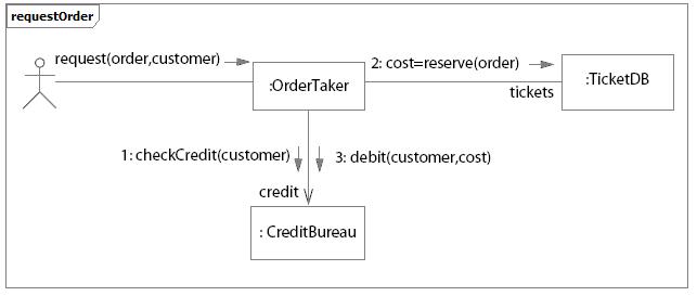
Example of Communication Diagram for an Ordering system
Component
In UML 2.0, a component is notated by a class symbol without the two protruding rectangles, as defined in UML 1.4. A <<component>> stereotype is used instead. Optionally, a component icon that is similar to the UML 1.4 icon can still be used in the upper-right corner of the component symbol.
UML 2.0 defines a component as being a structured class, which means that the collaboration between elements in its internal structure (parts) can be modeled to better describe its behavior. Parts are connected through connectors. Ports can be used to increase encapsulation level of a component through its provided and required interfaces. Refer to Concepts: Component and Concepts: Structured Class for more information.
Earlier versions of UML defined a special modeling element called subsystem, which was modeled as a package with interface. Also, components were used to structure the model in the physical architecture. In UML 2.0, components are used in a broad sense, across all parts of the model. Thus, there is no need for a special element to model subsystems anymore. Separate compartments for subsystem realization and subsystem specification in UML 1.x have become separate stereotypes (<<realization>> and <<specification>>, respectively) applied to components in UML 2.0. Another new component stereotype is <<subsystem>>, indicated to model large-scale components.
RUP suggests using components to model subsystems (refer to Guidelines: Design Subsystem for more information).
Composite Structure Diagram
Architectures can have specific collaboration between its elements, with parts and connectors not necessarily known at design time. A typical class diagram (as well as other static diagrams) wouldn’t be sufficient to clearly represent the roles, responsibilities, relationships and rules that apply on those elements.
To address these issues, UML 2.0 has added the composite structure diagram. It can depict the internal structure of a structured class (for example, component or class), including the interaction points of the structured class to other parts of the system. It shows the configuration of parts that jointly perform the behavior of the containing structured class.
Composite Structure Diagrams are used to draw internal content of Structured Classes (refer to Concepts: Structured Class for details and examples of Composite Structure Diagrams).
Sequence Diagram
UML 2.0 has several new features for sequence diagrams:
Fragments provide clearer semantics for how the behavior occurs within a sequence diagram. A combined fragment encapsulates portions of a sequence diagram, where separate flows can be modeled, showing how conditions lead to alternative paths of execution.
Interaction occurrences enable decomposition of interactions into reusable chunks. It is a useful way to share portions of an interaction between several other interactions.
In UML 1.x, one possible representation for loops was to use the loop condition written inside a Note. The Note was attached to the message or set of messages to be executed while the loop condition was true. In UML 2.0, there is a specific representation for loops.
In UML 2.0, sequence diagrams can show how objects are created and destroyed.
Execution of Occurrence shows the focus of control which an object executes at some point in time, when it receives a message.
With the new capabilities to represent fragments, interaction occurrences and loops, sequence diagrams can be used in two forms:
Instance form: describes a specific scenario in detail, documenting one possible interaction, without conditions, branches, or loops. This form is used to represent one use case scenario. Different scenarios of the same use-case are represented in different sequence diagrams. Modeling tools that support UML 1.x semantics only allow this form of representation.
Generic form: describes all possible alternatives in a scenario, taking advantage of new UML 2.0 capabilities like conditions, branches, and loops. This form can be used to represent several scenarios of the same use case in a unique sequence diagram, where it makes sense.
The figure below shows an example of a sequence diagram modeling different scenarios. The alt fragment shows two possible alternatives of message sequencing depending on if a condition is satisfied or not:
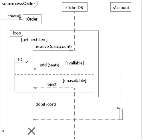
Example: Sequence diagram showing branches, loops and conditions
What’s New: Rational Unified Process
- From the Rational Unified Process 2003.06.01 to 2003.06.13
- From the Rational Unified Process 2003.06.00 to 2003.06.01
- From the Rational Unified Process 2002.05.00 to 2003.06.00
- From the Rational Unified Process 2001A.04.00 to 2002.05.00
- From the Rational Unified Process 2001.03.00 to 2001A.04.00
- From the Rational Unified Process 2000 to 2001.03.00
- From the Rational Unified Process 5.5 to 2000
- From the Rational Unified Process 5.1.1 to 5.5
From the Rational Unified Process 2003.06.01 to 2003.06.13
This service release includes the following changes:
-
Significantly greater compliance with accessibility standards
-
Updates to reflect UML 2.0 notation and terminology
-
Collaboration Diagram was renamed Communication Diagram
-
Implement Dependency was renamed Manifest Dependency
-
Component diagrams were updated with new component shape
-
Added Concept: Structured Class
-
Added comments about and example of sequence diagram new capabilities
-
Added comments about and examples of activity diagram new capabilities
-
Design Subsystems are now represented as components
From the Rational Unified Process 2003.06.00 to 2003.06.01
This is a service release including mostly minor changes. These include:
- Mandatory inputs have been defined for business modeling activities, and updated for other activities
- Activity “Deploy the Product” has been removed
- Updated ClearCase and ClearQuest tool mentors
- New model structuring guidelines for Rational XDE Develoloper .NET Edition
- New guideline for cost estimation using the Wide-Band Delphi technique
- Updated formatting of artifact and activity pages
From the Rational Unified Process 2002.05.00 to 2003.06.00
General Changes
-
Improved User-Configuration of the Process with RUP Builder
- The process has been refactored across all disciplines to create more than 60 selectable components, with improved ability to mix and match both plug-ins and components.
- Small, medium, and large project configuration templates provide a starting point for process configuration.
-
Formal and Informal Resources plug-ins allows flexibility in “level of ceremony”.
-
Contextual views into RUP are provided, such as the “developer” role view, and “getting started” view.
-
Improved generation of graphics and tables that reflect the selected process configuration.
-
Personal Process View or My RUP Personalization
- Each RUP user can create his/her own personalized view into RUP.
- Users can add links to external and internal resources.
-
Tool Integration
- New and Updated Tool Mentors:
- New tool mentors for Rational XDE, RUP Builder, and Rational Process Workbench.
- New tool mentors for using the RUP Web site, including searching, extended help and navigation.
- Extended Help launches a view in RUP.
- Search engine provides seamless search across RUP and RDN, and other new options.
- New and Updated Tool Mentors:
-
Content
- Guidelines, concepts, white papers, and checklists can now be attached to any process element, and so are now associated to the process elements where they are most relevant. The separate concept of a “Work Guideline” is gone.
-
Look and Feel
- The Web site’s navigation and layout has been upgraded to align with other Rational Web products.
Specific Changes and Additions to Content
-
Overview
- New “Getting Started” page provides answers to commonly asked questions for those new to RUP, and is presented along with relevant content as part of a specific process view in the tree browser. Note: The “Getting Started” view can be disabled by either a) for the entire project team, republishing the RUP Web site from RUP Builder and excluding the “Getting Started” process view or b) for the individual practitioner, using the “Tree Sets” feature of the tree browser to display a single process view of your choice.
-
RUP Lifecycle
-
Example Iteration Workflows provide a phase-based and time-based view into the process.
-
Disciplines
- Concepts pages are no longer all grouped under each discipline, but are now attached to the most relevant process element. Only those concepts and guidelines needed to understand the discipline as a whole are directly attached to the discipline.
- All technical reviewer roles, such as Business Model reviewer and Design Reviewer, have been replaced by a single Technical Reviewer role, which now performs all technical review activities across the disciplines.
-
Business Modeling Discipline
-
New support for modeling business rules, goals, and events.
-
Artifact: Business Object Model has been renamed to Business Analysis Model.
-
Requirements Discipline
- A generic “Software Requirement” has been added in support of more flexible process configuration by the project team.
- The guidance on storyboarding has been generalized by removing the dependency on use cases. (See Artifact: Storyboard).
- User Interface Design has been moved to the Analysis and Design Discipline.
- Artifact: User-Experience Storyboard has been added to the separate User Experience Plug-In to address user-experience design concerns.
-
Analysis and Design Discipline
- Data Modeling content has been upgraded to cover conceptual, logical, and physical database modeling.
- User Interface Design content has been moved from the Requirements Discipline and upgraded to reflect industry practices, including the new artifact Navigation Map.
-
Implementation Discipline
-
Artifact: Component has been replaced with Artifact: Implementation Element.
-
Improved guidance on component-based development and round-trip engineering.
-
New guidance on developer testing, debugging, and analysis of run-time behavior.
-
Test Discipline
- Separate templates for Master and Iteration Test Plans.
- New Test Strategy artifact.
-
Environment Discipline
-
Guidance on defining the organizational process environment has been broken out into a separate process packaged with RPW , leaving the RUP to focus on Project Environment only.
-
Improved guidance for implementing a process for a project, supported by the RUP tooling for customization and configuration of process.
-
New Artifact : Development Process and Activity: Tailor the process for the project, to describe the project-specific process.
-
All “Guidelines” type artifacts, such as “Design Guidelines” and “Business Modeling Guidelines”, have been replaced by a single more generic artifact, “Project-Specific Guidelines”.
-
Project Management Discipline
-
New Reviewer and Review Coordinator roles were added to better describe the review process.
From the Rational Unified Process 2001A.04.00 to 2002.05.00
Release 2002.05.00 is the successor to release 2001A.04.00. It adds or changes content in the following topic areas:
-
All RUP process variants are no longer installable from the Rational Suite installer. They can now be installed using RUP Builder, shipped with this release of RUP.
-
RUP Builder has been added:
-
Real-time specific content is componentized into its own plug-in, separately installable.
-
Microsoft variant is componentized into its own plug-in, separately installable.
-
The IBM variant is componentized into its own plug-in, separately installable.
-
Restructure and Extension of Test Discipline:
-
Changes
- Complete restructure of the Test Discipline Workflow and associated Workflow Details
- Removed Existing Workflow Details and replaced with Iteration Goal focused work elements.
- Rename and refactoring of existing Activities
- Restructure of existing Test roles
- Tester role now responsible for Test Implementation and Execution
- Overloaded Test Designer role activities and artifacts distributed to other roles
- Recast the following Activities
- Plan Test-now multiple activities across Role
- Design Test-now multiple activities across Role
- Execute Test-replaced by Execute Test Suite
- Evaluate Test-now multiple activities across Role
-
Additions
- Introduced the following Roles
- Test Manager
- Test Analyst
- Introduced the following Workflow Details
- Define Evaluation Mission
- Verify Test Approach
- Test and Evaluate
- Achieve Acceptable Mission
- Improve Test Assets
- Introduced the following Activities
- Agree Mission
- Identify Test Motivators
- Obtain Testability Commitment
- Assess and Advocate Quality
- Assess and Improve Test Effort
- Identify Targets of Test
- Identify Test Ideas
- Define Test Details
- Define Assessment and Traceability Needs
- Determine Test Results
- Define Test Approach
- Define Test Environment Configurations
- Identify Testability Mechanisms
- Define Testability Elements
- Implement Test Suite
- Execute Test Suite
- Analyze Execution Failure
- Introduced the following Artifacts
- Test Automation Architecture
- Test Data
- Test Environment Configuration
- Test-Ideas List
- Test Interface Specification
- Test Suite
- Test Log
- Introduced improved Developer Testing Guidance
- Test-First Design
- various concepts and guidelines focused on Testing for Developers
- Introduced the following Roles
-
Deletions
-
Removed the following Artifacts
- Test Model
- Test Procedure
- Test Package
- Test Subsystem
-
Added new Roadmap: Using Agile Practices with RUP.
-
Enhanced Key Concepts.
-
Improved navigation buttons for the Disciplines
-
Added new white paper “Content Management Defined”.
-
Added new sample configuration for Small Project.
-
Added new tool mentors:
- Tool Mentor: Profiling Memory Usage in Managed Code using Rational Purify and Rational Purify® Plus (Windows)
- Tool Mentor: Comparing Baselines using Rational ClearCase®
- Tool Mentor: Finding Actors and Use Cases Using Rational Rose RealTime®
- Tool Mentor: Detailing a Use Case Using Rational Rose RealTime®
- Tool Mentor: Structuring the Use-Case Model Using Rational Rose RealTime®
- Tool Mentor: Creating Use-Case Realizations Using Rational Rose RealTime®
- Tool Mentor: Managing Classes Using Rational Rose RealTime®
- Tool Mentor: Managing Collaboration Diagrams Using Rational Rose RealTime®
- Tool Mentor: Managing the Design Model Using Rational Rose RealTime®
- Tool Mentor: Managing Sequence Diagrams Using Rational Rose RealTime®
From the Rational Unified Process 2001.03.00 to 2001A.04.00
Release 2001A.04.00 is the successor to release 2001.03.00. It adds or changes content in the following topic areas:
-
New tool mentors created for new products:
-
Rational Rose RealTime Tool Mentors
-
Setting Up Version Control using Rational Rose RealTime with Rational ClearCase
-
Capturing a Concurrency Architecture using Rational Rose RealTime
-
Designing with Active Objects in Rational Rose RealTime
-
Rational ProjectConsole Tool Mentors
- Browsing Project Artifacts Using Rational ProjectConsole
- Creating a Static or Portable Copy of your Rational ProjectConsole Web Site Using Rational ProjectConsole
- Displaying Artifacts Related to Specific Objects on a Diagram Using Rational ProjectConsole
- Visiting Source Data Using Rational ProjectConsole
-
Rational QualityArchitect Tool Mentors
- Implementing an Automated Component Test using Rational QualityArchitect
-
New tool mentors for TestManager:
- Executing a Test Suite Using Rational TestManager
- Designing an Automated Test Suite Using Rational TestManager
-
“Core Workflow” has been changed to “Discipline” throughout.
-
Tree browser changes:
- The “Rational Unified Process” entry under Tool Mentors have been moved to “Process Engineer Toolkit”
- The Report Overview, Guidelines Overview, Examples Overview and Stereotypes Overview items have been moved from Artifact to Overview.
-
Addition of hyperlinked Tree Path at the top of each page to indicate location in RUP treebrowser
-
Upgraded graphics on buttons and icons.
-
Addition of new roadmap for Usability Engineering.
-
Incorporated new example Organization Web and example Project Web, based on the previous Wylie College artifact example set.
-
C-Sports example artifacts are now installed directly, instead of requiring a separate “unzip” installation.
-
The following new white papers have been added:
- RUP/XP Guidelines: Pair Programming
- RUP/XP Guidelines: Test-first Design and Refactoring
- A Comparison of RUP and XP
- The Rational Unified Process - An Enabler for Higher Process Maturity
From the Rational Unified Process 2000 to 2001.03.00
Release 2001.03.00 is the successor to release 2000. It adds or changes content in the following topic areas:
- A new workflow detail - Perform Architectural Synthesis - has been added to Analysis and Design, for use during the Inception phase for construction of an Architectural Proof-of-Concept, to help with technology selection, and show that the envisioned system is feasible.
- The role Architect has been renamed Software Architect, to distinguish that role from other architectural roles, for example, System Architect.
- Guidelines for the use of Microsoft® Windows DNA technology have been added to the Development Component Solutions roadmaps.
- Updated examples
- Tailoring guidance provided for all artifacts
- Updated Requirements Management Plan template
- Upgraded Requirements Management activities - term “traceability item” is used to generalize to artifact beyond just “requirement types”
- Guidance on how to manage requirements has been updated, including new Guidelines: Requirements Management Plan
- new Small Project roadmap, Tailoring Concepts, Small Project Development Case example, and Core Workflow Essentials
- Activity: Perform Configuration Audits has been reworked and enhanced
- Staffing sections have been added to those roles without one
- Best Practice: Visual Modeling has been fleshed out with more details
- The word “worker” has been changed to “role” for clearer understanding of the different roles a team member might perform.
- New tool mentors created for existing products:
- Tool Mentor: Creating Multiple Sites Using Rational ClearCase
- Tool Mentor: Evaluating Code Coverage Using Rational PureCoverage (UNIX)
- Tool Mentor: Detecting Run-Time Errors Using Rational Purify (UNIX)
- Tool Mentor: Finding Performance Bottlenecks Using Rational Quantify (UNIX)
- Tool Mentor: Archiving Requirements Using Rational RequisitePro
- Tool Mentor: Setting Up Rational Rose for a Project
- New tool mentors created for new products:
- Rational Process Workbench Tool Mentors
- Setting Up and Configuring Rational Process Workbench Tool
- Setting Up and Managing Rational Process Workbench Workspace
- Developing Process Models
- Managing Process Content
- Defining a Custom Process
- Publish a Process
- Rational Process Workbench Tool Mentors
From the Rational Unified Process 5.5 to 2000
Release 2000 is the successor to release 5.5. It adds or changes content in the following topic areas:
- Business Modeling Workflow
- Four new concepts pages have been added to clarify the role of business modeling in the context of e-business development.
- The page Concepts: Activity Based Costing outlines how the technique can be applied within the RUP.
- The page Concepts: Business Architecture explains our definition of what it means to architect a business.
- The page Concepts: Business Patterns gives some examples of useful patterns to apply in business modeling.
- The page Concepts: e-business Development gives our definition of the term.
- Three new workflow details have been added to the workflow diagram: “assess business status”, “describe current business”, and “explore process automation”.
- Workflow detail: Assess Business Status describes how you assess the status of the organization in which the eventual system is to be deployed (the target organization).
- Workflow detail: Describe Current Business talks about how you work to describe the current organization’s processes and structure in order to better understand needs for improvement.
- Workflow detail: Explore Process Automation talks about how you determine what can and should be automated of the business processes, how you understand how any existing systems (legacy) should fit into the organization, and how you derive system requirements from your business models.
- Five new artifacts have been added: “target-organization assessment”, “business vision”, “business glossary”, “business rules”, and “business architecture document”.
- Artifact: Target-Organization Assessment describes the current status of the organization in which the system is to be deployed. The description is in terms of current processes, tools, peoples’ competencies, peoples’ attitude, customers, competitors, technical trends, problems and improvement areas.
- Artifact: Business Vision is a general vision of the core project’s requirements, and provides the contractual basis for the more detailed technical requirements.
- Artifact: Business Glossary defines important terms used in the business engineering portion of the project.
- Artifact: Business Rules is a document capturing declarations of policy or conditions that must be satisfied.
- Artifact: Business Architecture Document provides a comprehensive architectural overview of the system, using a number of different architectural views to depict different aspects of the system.
- Requirements Workflow
- The page Concepts: User-Centered Design explains how to better meet user needs and improve user acceptance by focusing on the goals and need of the user when designing the user interface.
- The Artifact: Stakeholder Requests and Workflow Detail: Understanding Stakeholder Needs were improved to include more focus on collecting user and stakeholder profiles.
- Expanded User Profile section in the Vision Document.
- The Guidelines: Software Requirement Specification was expanded to include material from IGS Component Broker Engagement Methodology on Defining Non-Functional Requirements.
- Analysis & Design Workflow
- New artifacts:
- Reference Architecture
- Deployment Model
- Modified activity:
- Architectural Analysis to reflect the development of an architectural overview, selection of a reference architecture and the development of a deployment model.
- Software Architecture Document guidelines to describe the identification of architecturally significant change cases
- A new concepts page has been added to describe Web Architecture Patterns. This is taken from the book “Building Web Applications with UML”, with the kind permission of the author Jim Conallen and the publisher Addison-Wesley.
- A new guidelines page for class design called “Building Web Applications with UML” has been added.
- A small clarification has been added to the page Milestone: Lifecycle Architecture on the role of prototyping in elaboration, and to the page Phase: Inception, on the use of prototyping during architectural synthesis in inception.
- New artifacts:
- Environment Workflow
- There is a new entry in the Getting Started page, called Implementing the Process. This page and the pages it links to, will describe how you implement the RUP in different situations. For example, how to implement the RUP in a development organization; how to implement the RUP in a development project.
- The following artifacts has been added:
- Tool Guidelines
- The following Guidelines containing new information on how to use
artifacts have been added:
- Guidelines: Classifying Artifacts
- Guidelines: Review Levels
- The following Concepts have been added with valuable information on how
to implement process and tools:
- Concepts: Environment Practices
- Concepts: Implementing a Process in a Project
- Concept: Mentoring
- Concepts: Pilot Project
- Concepts: Implementing a process in an Organization has been revised.
- The role “Toolsmith” has been renamed “Tool Specialist” The new name better reflects its responsibilities, toolsmithing is just one of several responsibilities.
- Activity: Set Up Tools, Activity: Develop Tool Guidelines and Activity: Verify Tool Configuration and Installation have been added to the Tool Specialist.
- Several tool mentors that describe how to set up tools (one tool mentor for each Rational Tool) has been added. They are all referenced from the new Activity: Set Up Tools.
- The four (4) workflow details in the Environment workflow have been updated with the new activities.
- The Development Case HTML template has been completely revised.
- Test Workflow
- Artifact sets now reflect an artifact set for Test.
- Two new test artifacts:
- Test Results - the data captured during the execution of test which is used as input for the Evaluation of Test and to calculate the key measures of test.
- Test Evaluation Summary (formerly a report) - created during the Evaluation of Test, this artifact organizes and presents the test results and key measures of test for review and assessment, and contains recommendations for future test efforts.
- The Workflow Details for Execute Test and Evaluate Test have been revised to reflect these two new artifacts.
- The Guidelines for Test Cases contains new information and guidelines for deriving test cases from use cases.
- Modified/Clarified the following test activities:
- Execute Test - revised this activity to focus the effort on setting-up and execution of test, including recovering from halted or incomplete test execution.
- Evaluate Test - revised to include the analysis of the test results, logging change requests, and generating the Test Evaluation Summary.
- Deployment Workflow
- This workflow has been completely re-worked and has a new introduction, workflow activity diagrams and workflow details
- New Activity Diagram
- Deployment Workflow Activity Diagram
- New Artifacts:
- Bill of Materials
- Product Artwork
- Deployment Unit
- Product
- New Roles:
- Graphic Artist
- New Activities:
- Define Bill of Materials
- Manage Acceptance Test
- Release to Manufacturing
- Verify Manufactured Product
- Provide Access to Download Site
- Create Product Artwork
- Configuration and Change Management Workflow
- The Configuration Management section was updated to align with Unified Change Management concepts in the following areas.
- New Activity
- Project Repository
- Workspace
- Changes to Activities:
- Establish CM Policies
- Set Up CM Environment
- Create Integration Workspace
- Create Development Workspace
- Make Changes
- Deliver Changes
- Update Workspace
- Create Baselines
- Promote Baselines
- Create Deployment Unit
- New Tool Mentors:
- Setting Up the Implementation Model with UCM
- Working on UCM Activities
- Delivering Your Work using Rational ClearCase
- Updating Your Project Work Area using Rational ClearCase
- Linking Configuration Management and Change Request Management
- New Concepts:
- Unified Change Management
- Project Management Workflow
- The deployment related activities are now owned by the Deployment Manager role. The Project Manager role has been made responsible for the development of the Quality Assurance Plan artifact.
- Implementation Workflow
- A new artifact, Build, has been added.
- The role of System Integrator has been renamed Integrator, and this new role assumes the integration responsibilities that previously belonged to the Implementer.
- The purpose of the artifact Implementation Subsystem has been clarified, and its relationship to the artifact Design Subsystem explained.
- Under the section on Phases, we have added a description of the Transition
phase, and a sample iteration plan for the Transition phase. For each of the
phases, we have provided, courtesy of
Ensemble Systems
Inc, a more detailed Microsoft® Project® template which goes to the activity
level.
- Artifact sets have been reorganized:
- There is now one artifact set for each core workflow
- An artifact is considered to “belong to” the core workflow in which it is primarily developed
- Added new road maps:
- Developing e-business Solutions: A road map has been added that explains how to use the RUP for e-business development.
- Re-organization and renaming of Iteration Workflows to Phases.
- Added Analyst Studio Tool Mentor section.
- Added new guideline, Guideline: Review Levels.
- Improvement in the performance of the treebrowser.
- Added HTML Templatesfor artifacts that currently have Microsoft® Word® and Adobe® FrameMaker® templates. Included pointers into the HTML template from the artifact pages and removed the embedded Annotated Outlines.
- All Word Templates have been compressed into a zip file.
- Added Collegiate Sports Paging System example to demonstrate e-business application.
- All examples are now compressed into a zip file.
- Now supports foreign languages and JDK1.1:
- Added instruction for translating the Rational Unified Process to other foreign languages.
From the Rational Unified Process 5.1.1 to 5.5
Release 5.5 is the successor to release 5.1.1. It adds or changes content in the following topic areas:
- Improved ‘Getting Started’ content, including automatic display of getting started topics on product start-up. The automatic start-up may be disabled at the user’s discretion. This feature includes and subsumes the ‘Guided Tour’ concept which appeared in version 5.0. The ‘old’ Guided Tour is now expanded under the ‘Process Roles’ link on the ‘Getting Started’ window.
- Simplification of the treebrowser.
- Improved process Overview.
- Re-designed core workflows, now using Workflow Detail Overviews to express workflows. The workflows are expressed as activity diagrams using workflow details to provide an easier to understand picture of how the work on the project is done.
- Expanded ‘Workflow Details’; these have now become the focal point for the expression of workflows in the process.
- Improved process configuration and implementation content in the ‘Environment Workflow’.
- Improved cross-referencing, to improve product usability. Especially noteworthy are the links between Artifacts and Activities (see Artifact: Software Architecture Document for an example).
- Expanded ‘Project Management Workflow’ content, including metrics and estimation, project planning and project control.
- Removal of Rational SoDA and Rational Rose model templates from the RUP. These templates are now provided with their respective Rational Software products and are automatically installed when those products are installed. Use of these template is still described in appropriate RUP Tool Mentors.
- Java Programming Guidelines have been added.
- Added the concept of Roadmaps, which describes how the process can be tailored to a particular style or type of software development. There are two Roadmaps in this release: one for component-based development, and one expressing how a focus on quality manifests itself throughout the lifecycle. We expect more to be included in future releases.
- Two new white papers: one covering strategies for traceability, and another describing modeling Web applications with UML.
- Added Change Request Management process information in Configuration and Change Management workflow.
- Updated Vision template to include more and proper emphasis on stakeholders/user and needs/requests.
- New artifacts:
- Software Requirements Specification in the Requirements workflow; templates are included for use both with and without use-case modeling.
- Requirements Management Plan for setting up project requirement artifacts.
- Updated document templates to include consistent formats styles, and informational guidance.
- FrameMaker templates now available from the RUP Resource Center.
- Expanded links and cross-references:
- between artifacts and the activities that use, produce or modify them
- between activities and the workflow details that organize them.
Working with Extended Help
Extended Help lets you view Rational Unified Process (RUP) instructions on topics that are relevant to the Rational tools you use. For example, you can start Extended Help from Rational Rose without interrupting your workflow.
In order to use Extended Help, you must install RUP. Extended Help becomes available as soon as the installation is complete.
When you select Extended Help from another Rational tool’s Help menu, the Extended Help topics appear in a tree panel beside the RUP content. The specific tree panel is identified by the title “Extended Help” and the tool name.
| The Extended Help tree panel lists topics that are applicable to the tool and context in the tool that you are using. | Extended Help tree panel screenshot |
The rest of this document explains how to launch and navigate Extended Help.
Using Extended Help
To use Extended Help, follow these steps.
| In a Rational tool (for example, Rational Rose), click Help > Extended Help on the tool’s menu bar. | Extended Help tree panel screenshot |
| If you have more than one installed or published RUP Web site, an Extended Help Location Chooser dialog box appears, prompting you to choose the location from which you want to view Extended Help topics. For each RUP Web site, there is an Extended Help, and each Web site might have different topics pertaining to the tool that you are using. In the list at the top of the dialog box, select your desired location. If you want, you can select a check box that makes this the default location for the next time you view Extended Help. Another check box allows you choose to never show the dialog box again. If you choose to never show the dialog box again, the default Extended Help location will subsequently be the one that launches automatically. In this example, the user has chosen to make the selected location the default one and to never show this dialog box again. | Extended Help tree panel screenshot Extended Help tree panel screenshot |
| To view the topics in the More Content folder, double-click to expand that folder in the tree. | Extended Help tree panel screenshot |
Content Management Using the Rational Unified Process
by Michael McIntosh. All Rights Reserved.
Michael McIntosh is a freelance writer, project methodologist, and Web consultant. Since 1987, he has trained and consulted in project management, Web development, and computer networking. Formerly with Vignette Corporation, he was instrumental in the development of Vignette’s Solution Methods (VSM) 3.0. He lives in Austin, Texas, with his wife, Julie, and son, Willie. Michael can be reached via e-mail.
A PDF version
of this article is available, however, you must have
Adobe Acrobat installed
to view it. There are additional white papers available on the IBM Web site.
Abstract
This paper presents an overview of content management, particularly as it relates to delivering content on the Web. Content management represents a collection of tools and methods that are used together to collect, process, and deliver diverse types of content. The scope of content management is broad, and its challenges are many.
Collecting and processing content intended for a Web site is a more complex and time-sensitive process than many legacy document management systems are designed to handle. Organizations have turned to the Web as a means of delivering information to, and communicating with, their customers; however, simply uploading content to a Web site does not mean it will reach the proper people or that it will meet their information needs.
Content management projects entail far more than buying or building an application that provides content workflow. The development of a content management solution is a group of related software projects-made up of database, production workflow, content delivery, and Web applications-making it a perfect candidate for an established software development framework such as RUP.
Developing Large-Scale Systems with the Rational Unified Process
by Maria Ericsson. All Rights Reserved.
A PDF version of this article is available, however, you must have
Adobe Acrobat
installed to view it. You can also download this and other Rational Unified Process
(RUP) white papers from the
IBM Web site.
Abstract
There is a considerable increase in complexity when developing large-scale systems. Not only does it require that you are capable of comprehending a more complex set of artifacts, you are also introducing overhead since you need to manage a larger set of resources. This paper describes an architectural pattern that is used to help control the added complexity overhead. The architectural pattern is referred to as a system of interconnected systems.
This paper introduces an architectural pattern for systems of interconnected systems. This construct allows recursion not only within one model, it considers each subsystem a system in its own right and the recursion is between all the artifacts sets of each of the systems. The introduced architecture is used for systems that are implemented by several communicating systems. Each involved system is described by its own set of models, separate from other systems’ models.
The examples given in this paper illustrate that the architecture for modeling systems of interconnected systems is useful in many different application areas. In fact, you may use the suggested architecture for any system where it ’s possible to view the different parts as systems of their own.
Layering Strategies
by Peter Eeles. All Rights Reserved.
Peter Eeles is a Technical Lead in Rational’s Regional Services Organization, based in the UK. He has spent the majority of his 16 year career developing large-scale distributed systems and, in 1998, co-authored his first book, “Building Business Objects”. A regular speaker at conferences throughout Europe, Peter spends most of his time consulting in software architecture, and in helping organization adopt the Rational Unified Process. He lives in the UK with his wife, Karen, and sons Daniel, Thomas and Christopher. Peter can be reached via e-mail at peter.eeles@rational.com. .
A PDF version
of this article is available, however, you must have
Adobe Acrobat
installed to view it.
Abstract
A number of techniques exist for decomposing software systems. Layering is one example and is described in this paper. Such techniques address two main concerns: most systems are too complex to comprehend in their entirety, and different perspectives of a system are required for different audiences.
Layering has been adopted in numerous software systems, and is espoused in many texts and also in the Rational Unified Process (RUP). However, layering is often misunderstood and incorrectly applied. This paper clarifies what is meant be layering, and discusses the impact of applying different layering strategies.
Modeling Web Application Architectures with UML
By: Jim Conallen, Rational Software. All Rights Reserved. June 1999 A version of this material appears in the October 1999 (volume 42, number 10) issue of Communications of the ACM.
A PDF version of this article
is available, however, you must have
Adobe Acrobat
installed to view it. You can download other Rational Unified Process (RUP) white papers from the
IBM Web site.
Abstract
Web applications are becoming increasingly complex and mission-critical. To help manage this complexity, they need to be modeled. UML is the standard language for modeling software-intensive systems. When attempting to model Web applications with UML, it becomes apparent that some of its components don’t fit nicely into standard UML modeling elements. To stick with one modeling notation for the entire system (Web components and traditional middle tier components), UML must be extended. This paper presents an extension to the UML using its formal extension mechanism. The extension is designed so that Web-specific components can be integrated with the rest of the system’s model, and to exhibit the proper level of abstraction and detail for suitable for designers, implementers, and architects of Web applications.
System Variants
Written by Haakan Dyrhage. All Rights Reserved.
A PDF version of this article
is available, however, you must have
Adobe Acrobat
installed to view it. You can download other Rational Unified Process (RUP) white papers from the
IBM Web site.
Abstract
This paper discusses what variants of systems are and how to manage them. You do not need to read this to understand the RUP; on the contrary, it should be treated as an extension to the RUP. The last section briefly discusses how the RUP would be affected by the introduction of variants and variability.
This is an area in which the RUP will improve and expand in the future and this paper gives a first taste of that.
Testing Embedded Systems - Do You Have the GuTs for It?
by Vincent Encontre. All Rights Reserved.
Vincent Encontre is the Director for Embedded and RealTime, Automated Testing Business Unit, based in Rational’s new engineering center in Toulouse, France. When he’s not traveling, attending meetings, or answering zillions of emails, Vincent looks at the destiny of Rational Test RealTime as a Rational product and as reusable technologies for next generations of Rational products. Vincent has extensive experience in embedded modeling and testing technologies and best practices. Prior to Rational and ATTOL, Vincent spent 13 years at Philips, then at Verilog, designing, marketing, and supporting software engineering tools, believing these tools could help build better software faster. In his spare time, Vincent plays soccer with his three boys and a few others, and just enjoys the wonderful art de vivre from the south of France (before it’s too late…).
A PDF version
of this article is available, however, you must have
Adobe Acrobat
installed to view it.
You can download other RUP white papers from the IBM Web site.
Abstract
This paper gives a general introduction to testing embedded systems followed by a discussion of how embedded systems’ issues affect testing processes and technologies, and how Rational Test RealTime provides solutions to these issues.
It presents an overview of the process of six incremental steps used to test embedded systems. Considering this process (taking into account the full spectrum from very small to very large systems), and the specific characteristics and constraints of embedded systems, we have deduced a set of requirements that an ideal technology must possess to address the testing of embedded systems. Rational Test RealTime, the new Rational offering to the embedded systems domain, exemplifies large portions of this ideal technology.
The Ten Essentials of RUP - The Essence of an Effective Development Process
by Leslee Probasco. All Rights Reserved.
A PDF version of
this article is available, however, you must have
Adobe Acrobat
installed to view it.
You can download other Rational Unified Process (RUP) white papers from the
IBM Web site.
Abstract
To effectively apply a software development process such as the RUP, it’s important to first understand its key objectives, why each is important, and how they work together to help your development team produce a quality product that meets your stakeholders’ real needs.
Using the RUP for Small Projects: Expanding upon eXtreme Programming
by Gary Pollice, Rational Software. All Rights Reserved.
A PDF version of this article is available, however, you must have
Adobe Acrobat
installed to view it. You can also download this and other RUP white papers from the
IBM Web site.
Abstract
RUP is a complete software-development process framework that comes with several out-of-the-box instances. Processes derived from RUP vary from lightweight-addressing the needs of small projects with short product cycles-to more comprehensive processes addressing the broader needs of large, possibly distributed, project teams. Projects of all types and sizes have successfully used RUP. This white paper describes how to apply RUP in a lightweight manner to small projects. We describe how to effectively apply eXtreme Programming (XP) techniques within the broader context of a complete project.
Rational Unified Process: White Papers
The RUP includes a number of white papers, listed below.
- Disciplines
- Requirements
- Architecture
- Design
- Implementation
- Assessment
- Management
- Configuration & Change Management
- The Ten Essentials of RUP
- From Waterfall to Iterative Lifecycle
- The Estimation of Effort Based on Use Cases
- A Comparison of RUP and XP
- Using the RUP for Small Projects: Expanding upon eXtreme Programming
- Reaching CMM Levels 2 and 3
- An Enabler for Higher Process Maturity
- Developing Large-Scale Systems with the Rational Unified Process
- System Variants
- Tools
If you have Internet access, some of the RUP white papers can be downloaded
from the IBM Web site.
A Comparison of RUP and XP
by John Smith, Rational Strategic Services Organization, International Branch. All Rights Reserved.
A PDF version of this article
is available, however, you must have
Adobe Acrobat
installed to view it. You
can download this and other RUP white papers from the
IBM Web site.
Abstract
Labeling RUP as heavyweight and XP as lightweight without further qualification does both a disservice by obscuring what each is and what each was intended to do. And, when done in a pejorative way, it’s simply meaningless posturing. It is the implementations of these as processes that will be either “heavyweight” or “lightweight”, and they should be as heavy or light as circumstances require them to be.
XP is not a free form, anything goes discipline-it focuses narrowly on a particular aspect of software development and a way of delivering value, and is quite prescriptive about the way this is to be achieved.
RUP’s coverage is much broader and just as deep, which explains its apparent “size”. However, at the micro level of process, RUP occasionally allows and offers equally valid alternatives, where XP does not; for example, the practice of pair programming, which is required by XP. This is not intended as a criticism of XP; simply an illustration of how XP, as its name implies, has narrowed its focus.
Applying Requirements Management with Use Cases
by Roger Oberg, Leslee Probasco, and Maria Ericsson. © Copyright 2000 by Rational Software Corporation. All Rights Reserved. Technical Paper TP505 (Version 1.4)
A PDF version of this article
is available, however, you must have
Adobe Acrobat installed to view it. There are additional white papers available from the IBM Web site.
Abstract
Whether you are new to or somewhat familiar with requirements management and are interested in requirements process improvement, this paper offers a framework with which to develop your own approach.
The need to manage requirements is not new. If your projects are not regularly satisfying customers, meeting deadlines, and staying within budget, you have reason to reconsider your development approach. In doing so, if you determine that requirements-related problems are undermining your development efforts, you have reason to consider better requirements-management practices.
The requirements management practices summarized in this paper embody the collective experience of thousands and are the well-considered opinions of a number of individuals who have spent years working with customers in the field of requirements management. We suggest that this overview of their contributions-and the more thorough presentation of them made in the RUP-represent a best practice in requirements management.
RUP/XP Guidelines: Pair Programming
By Robert C. Martin
Object Mentor, Inc.
mailto:rmartin@objectmentor.com
www.objectmentor.com
All Rights Reserved.
A PDF version
of this article is available, however, you must have
Adobe Acrobat installed
to view it. You can download other white papers from the
IBM Web site.
Abstract
Pair programming is a well-tested, well accepted alternative to code reviews. More than that, it’s a fundamentally different way to write software. The benefits go far beyond productivity and quality, and affect such things as the robustness and morale of the team.
RUP/XP Guidelines: Test-first Design and Refactoring
By Robert C. Martin
Object Mentor, Inc.
mailto:rmartin@objectmentor.com
www.objectmentor.com
All Rights Reserved.
A PDF version of this article
is available, however, you must have
Adobe Acrobat installed to view it. You
can download other white papers from the
IBM Web site.
Abstract
This paper demonstrates the techniques of refactoring in the presence of test-first design and conveys a programming attitude. A program is not done when it works; a program is done when it works and when it’s as simple and clean as possible.
Reaching CMM Levels 2 and 3 with the Rational Unified Process
by Jas Madhur, et al., Rational Software Canada. All Rights Reserved. (Version 1.0)
A PDF version of this article
is available, however, you must have
Adobe Acrobat
installed to view it. You
can download other Rational Unified Process (RUP) white papers from the IBM Web site.
Abstract
The Software Engineering Institute’s (SEI) Capability Maturity Model (CMM) provides a well-known benchmark of software process maturity. The CMM has become a popular vehicle for assessing the maturity of an organization’s software process in many domains. This white paper describes how the RUP can support an organization that is trying to achieve CMM Level-2 (Repeatable) and Level-3 (Defined) software process maturity levels.
The Estimation of Effort Based on Use Cases
by John Smith. All Rights Reserved.
A PDF version of
this article is available, however, you must have
Adobe Acrobat
installed to view it.
You can also download this and other Rational Unified Process (RUP) white papers from the
IBM Web site.
Abstract
It should be possible to form estimates of size and effort that development will require, based on characteristics of the use-case model, which captures the functional requirements. So shouldn’t there be a use-case based equivalent of function points?
This white paper looks at some important techniques for estimating development effort that can be included in the RUP. A framework for estimation, based on use cases, is presented here. This framework considers the idea of use-case level, size, and complexity for different categories of system.
The Rational Unified Process - An Enabler for Higher Process Maturity
by Annie Kuntzmann-Combelles, Q-Labs France and Philippe Kruchten, Rational Software Canada. All Rights Reserved. (Version 1.0)
A PDF version of this article
is available, however, you must have
Adobe Acrobat
installed to view it. You
can also download this and other Rational Unified Process (RUP) white papers
from the IBM Web site.
Abstract
This paper highlights the key concepts that a mature organization-a Level 3 development unit-has to demonstrate and how the RUP components match these requirements.
Both high project maturity and organization maturity are addressed. In addition, section 4 provides some good ideas on getting started with the RUP and reports on some of the major benefits observed by early adopters in various contexts.
Traceability Strategies for Managing Requirements with Use Cases
by Ian Spence, Rational U.K., and Leslee Probasco, Rational Canada, © Copyright 1998 by Rational Software Corporation. All Rights Reserved. (Version 1.0)
A PDF version
of this article is available, however, you must have
Adobe Acrobat installed
to view it. You can download other Rational Unified Process (RUP) white papers
from the
IBM Web site.
Abstract
In many commercial applications of use-case modeling techniques the use-case model must be combined with more traditional requirements capture techniques to provide a requirements management process acceptable to all of the stakeholders involved in the project. This paper explores the traceability strategies available to organizations adopting use-case modeling techniques as part of their requirements management strategy.
From Waterfall to Iterative Lifecycle - A Tough Transition for Project Managers
Philippe Kruchten Rational Software Corp. All Rights Reserved.
A PDF version of this article
is available, however, you must have
Adobe Acrobat
installed to view it. You
can download other Rational Unified Process (RUP) white papers from the
IBM Web site.
Abstract
In this paper, some of the challenges of iterative development are described from a project manager’s perspective. This document also discusses some of the common “traps” or pitfalls we’ve seen through our consulting experience, and from reports and war stories related by our colleagues.
The waterfall model made it easy on the manager and difficult for the engineering team. Iterative development is much more aligned with how software engineers work, but at some cost in management complexity.
Although iterative development is more difficult than traditional approaches the first time you do it, there’s a real long-term payoff. Once you understand how to do it well, you’ll find you’ve become a much more capable manager, and you’ll find it easier to manage larger, more complex projects. And once you get an entire team to understand and think iteratively, the method scales are much better than traditional approaches.
CSPS Creative Design Brief
**Collegiate Sports Paging Service
Creative Design Brief**
Version 1.0
Revision History
| Date | Version | Description | Author |
| October 6, 1999 | 1.0 | Initial version | Context Integration |
Table of Contents
- Introduction
- Overview
- [Visually Supporting the Function of the Site (the mood)](#Visually Supporting the Function of the Site (the mood))
- [Determining the Color Scheme](#Determining the Color Scheme)
- [Fonts and Scrolling](#Fonts and Scrolling)
- [Site Navigation and Page Layout](#Site Navigation and Page Layout)
- [Graphics Standards](#Graphics Standards)
- [Browsers, Frames, and Other Standards](#Browsers, Frames, and Other Standards)
- [Personalization Elements](#Personalization Elements)
- Conclusion
Creative Design Brief
Introduction
Purpose
This document presents standards to be used during the design of the User Interface (UI) for the Collegiate Sports Paging System.
Scope
This document encompasses all UI elements that are used in the web site.
Definitions, Acronyms and Abbreviations
See Glossary.
References
Overview
The visual elements of the Sports Paging Service web site will fit in line with WebNewsOnLine’s current web presence. This site will add the personalization and customization required by the paging service. In general, it will maintain the look and feel of WebNewsOnLine’s current site. Some of the additions required by this service are a login screen, user profile editing, customized link list, and maintaining a history of past pages.
Visually Supporting the Function of the Site (the mood)
The mood of this site will follow the lead of the current news site. The focus of the paging service is sports news and scores, so the mode will model an online news web site. The priority is content over a flashy visual design. An overall conservative look will consist of a white background, black serif text, columns with news articles and photos, and tables with user profile information and a linked list of the paging history.
Determining the Color Scheme
A color should add to the message conveyed by the web site. A professional and conservative site should use cool and neutral colors. Bright or warm colors can be used as accents. The paging site will use the same color palette enforced in the main web site.

Figure 1 - Web site color palette
Colors will also be used to highlight important items on the paging subscriber’s homepage. Links will remain the standard blue color used throughout the site. All body text will be black, while table headings will be white on various background colors.
Fonts and Scrolling
The paging service web site’s fonts and scrolling behavior will mimic the WebNewsOnLine web site. Serif fonts are used for most of the text for readability. The width of the page is limited to fit inside a 640x480 screen without scrolling horizontally. The user scrolls up and down to view content. News articles generally are on one screen taking vertical space as needed.
Site Navigation and Page Layout
The width of the page is limited to 600 pixels with about 20% of the horizontal space allocated for the sidebar on the left. The body area is given the remaining 80%. The banner section includes the logo, banner advertisements, and links to the main sections of the news web site.
Figure 2 - Page Layout Standard
The sidebar contains the sub-links for the paging service web site. These links will allow the user to go back to their home page and traverse recent articles and scores postings. The footer of the body section will include more banner advertisements.
Graphics Standards
Visitors to the paging site will be connecting at speeds from T1 lines down to 28.8 modems. The site is designed to load fast, using a minimum of photos and other graphic images. Outside of the main logo, page header and advertisements, only a few other graphic images are used on each page. There may be only one or two photos corresponding to a news article.
This site will not use any JavaScript rollovers or animation (outside of any animation included in the banner advertisements). This will ensure that download speeds are fast and that the web site is compatible with new and older browsers.
Browsers, Frames, and Other Standards
Visitors to the site will be using Netscape Navigator, Internet Explorer, and other popular web browsers. Browser versions will vary, but most will be using 3.0 versions or higher. The HTML code and layout techniques used on the site will support most browser brands that support HTML 3.0 or higher.
Frames will not be used on the sports paging web site. The entire screen is loaded from scratch when a new link is chosen. This behavior matches the web site.
A web-safe color palette has been chosen to ensure that the site looks the same on various platforms, browsers, and screen color configurations.
Personalization Elements
The top section of the subscriber’s page consists of a welcome phrase including their name. This ensures to the user they have properly logged in and the information on the screen is customized for them.
The second element is a header indicating the date and time of the last page. This is an indicator that the content on the home screen relates to the page received at that date and time.
The two primary elements of the paging service are news articles and game scores. These two are grouped in tables on the user’s home page. These tables include headlines and scores reports with links to the full news story and game report.
At the bottom of their homepage, the subscriber will find a table of links to recent pages to access historical page information. If this list grows large, a link will be added to “view all pages” which will send them to another page with the complete list of page links.
Conclusion
The visual design for the sports paging service will be the same as the web site. The look and feel can be characterized as a news and content focused site that is geared toward being readable, easy to navigate, with fast downloading. Visitors will be connecting speeds varying from very fast T1 lines to slower modems, so graphics are kept to a minimum. The HTML used is compatible with all of the popular browsers down to their 3.0 versions.
The subscriber’s home page will consist of personalized elements or units on the screen. These elements contain a welcome message, the news headlines and game score links, and last pages links. Banner ads on these screens can also be customized for subscriber preferences.
**Collegiate Sports Paging Service
Design Comps**
Version 1.0
Revision History
| Date | Version | Description | Author |
| October 8, 1999 | 1.0 | Initial version | Context Integration |
- Introduction
- Overview
- [Screen 1 : Login to Paging Service](#Screen 1 : Login to Paging Service)
- [Screen 2 : Subscriber’s Paging Homepage](#Screen 2 : Subscriber’s Paging Homepage)
- [Other Screens](#Other Screens)
Design Comps
Introduction
Purpose
This document presents design concepts (or comparables) for several major User Interface (UI) components for the Collegiate Sports Paging Service.
Scope
This document encompasses major UI designs that may be used in the web site.
Definitions, Acronyms and Abbreviations
See Glossary
References
Overview
Design comps give examples of what the basic screens will look like for a web site. They are not exact representations and only exist as graphic images (no HTML). These may also not represent every screen in the system, but are a representative group that give a picture of the overall look and feel of the site.
Screen 1 : Login to Paging Service
Figure -1 - Log on to paging service screen
This diagram of the login screen shows the general layout of the WebNewsOnLine Sports Paging Service web page. The user is presented with the fields for username and password. If they are not currently subscribers, a paragraph explains the features of the Paging Service. Along with the button to login to the service, a button is provided to subscribe for those who aren’t currently members. Links on the left side of the screen indicate the options available for sports paging. Advertisements on the top, bottom and left are customized for the paging service subscriber once they have logged in.
Screen 2 : Subscriber’s Paging Homepage
Figure -1 - Subscriber’s home page
Screen #2 is the first page the subscriber sees when they log into the service. It indicates the date and time for the current page. The news article headlines are listed along with a link to the full article text. Scores are listed with links to the full article coverage for the game. On the bottom of the page, there is a list with the recent dates and times for pages sent. Subscribers can click to view the past news headlines and scores signaled by pages. Another link takes the viewer to a list of all of their pages.
Other Screens
There will be several other screens that comprise the Sports Paging Service. Most of the content for the news articles and game summaries will link to existing content on the WebNewsOnLine web site. Another screen will allow the subscriber to edit their preferences, choosing the sports teams and athletes they of interest.
CSPS Development Case 1.0
**Collegiate Sports Paging System
Development Case**
Version 1.0
Revision History
| Date | Version | Description | Author |
| October 1, 1999 | 1.0 | Initial version | Context Integration |
Table of Contents
- Introduction
- [Overview of the Development Process](#Overview of the Development Process)
- [Phases](#Iteration Workflows)
- [Business Modeling](#Business Modeling)
- Requirements
- [Analysis and Design](#Analysis and Design)
- Implementation
- Test
- Project Management
- Deployment
Introduction
Purpose
This document presents the manner in which the RUP and ContextWISE development methodology will be used for the Collegiate Sports Paging System project for WebNewsOnLine.
Scope
This development case applies to the Inception, Elaboration, Construction, and Transition phases of the Collegiate Sports Paging System project.
Definitions, Acronyms and Abbreviations
ContextWISE is the Web-optimized methodology developed by Context Integration. It is an adaptation of the Rational Unified Process for Web-based projects.
Artifacts are deliverables produced during various activities.
References
None.
Overview
The remainder of this document describes ways in which the RUP will be adapted for this project. Where the RUP will be used as is, this is so noted.
Section 2 contains an overview of the development process, including project management and quality assurance activities. Section 3 describes the iteration workflows for the Elaboration and Construction phases. Section 4 describes Business Modeling workflows.
Overview of the Development Process
This project will consist of a full Inception phase, an Elaboration phase, a three-iteration Construction phase, and a full Transition phase. Design and code reviews will take place at key iteration milestones, and project quality reviews will be conducted at the end of each phase.
Phases
Inception
Define the Scope and Vision
We will work with the stakeholders of the system to be developed to define the vision and the scope of the project. This will be done using a facilitated session and will produce the Vision document as an artifact. An initial version of the project risks will also be developed at this point.
Outline and clarify the functionality that is to be provided by system.
We will conduct sessions to collect stakeholders’s opinions on what the system should do. We will outline the Use-Case Model at this point as a basis for subsequent design activities. A Glossary of terms specific to this project will also be developed.
Consider the feasibility of the project, and define the Software Development plan.
With input from the use-case modeling, we will translate the Vision into economic terms, updating the Business Case, factoring in the project’s investment costs, resource estimates, the environment needed, and success criteria (revenue projection and market recognition). We will also update the Risk List to refer to the identified use cases and add new identified risks. We will develop the initial Software Development plan to more fully map out the project phases.
Elaboration Workflows
To be defined later in the project.
Construction Workflows
To be defined later in the project.
Transition Workflows
To be defined later in the project.
Business Modeling
We will refine the Glossary during this activity.
Artifacts
The following artifacts are produced during this workflow:
| Artifact | Tools Used | Formal Deliverable? |
| Glossary | Microsoft® Word® | Yes |
Key Input Artifacts
None.
Workflow
The development of a Supplementary Business Specification, Business Analysis Model, and Business Use Cases will be omitted from the standard workflow.
Requirements
We will capture requirements through the development of use-cases. Use-cases define actors (individuals who interact with the system) and use-cases (descriptions of how the actors interact with the system). During the development of use-cases (which will be done through facilitated sessions), a set of non-use-case requirements will also be captured into the Supplementary Specifications document.
Artifacts
The following artifacts are produced during this workflow:
| Artifact | Tools Used | Formal Deliverable? |
| Vision | Microsoft Word | Yes |
| Actors | Rational Rose | No |
| Boundary Classes | Rational Rose | No |
| Glossary | Microsoft Word | Yes |
| Supplementary Specifications | Microsoft Word | Yes |
| Use Cases (updated) | Rational Rose, Microsoft Word | No |
| Creative Design Brief | Microsoft Word | Yes |
| Navigation Map | Microsoft Word | Yes |
| User Interface Prototype | Microsoft® PowerPoint®, Microsoft Word | Yes |
Reports
The following reports are generated during this workflow:
| Report | Tools Used | Formal Deliverable? |
| Use-Case Survey | Microsoft Word | Yes |
Key Input Artifacts
| Artifact | Tools Used | Formal Deliverable? |
| Glossary | Microsoft Word | Yes |
Maintenance of Input Requirements
None needed - keep as is.
Workflow
The development of two artifacts is added to the standard workflow - Creative Design Brief and Navigation Map. We also move the generation of the User Interface Prototype into the Inception phase.
Analysis and Design
The use-cases developed during the Requirements workflow form the basis for subsequent analysis and design. Object-oriented design and analysis techniques will be used to complete the use-cases initially developed, produce the analysis and design object models, the data model, and the software architecture document.
Artifacts
The following artifacts are produced during this workflow:
| Artifact | Tools Used | Formal Deliverable? |
| Data Model | Rational Rose | Yes |
| Design Model | Rational Rose | Yes |
| Database Design | Rational Rose | Yes |
| Software Architecture Document | Microsoft Word | Yes |
Reports
The following reports are generated during this workflow:
| Report | Tools Used | Formal Deliverable? |
| Use-Case Survey | Microsoft Word | Yes |
Key Input Artifacts
| Artifact | Tools Used | Formal Deliverable? |
| Glossary | Microsoft Word | Yes |
| Supplementary Specifications | Microsoft Word | Yes |
| Use Cases (updated) | Rational Rose, Microsoft Word | No |
| Creative Design Brief | Microsoft Word | Yes |
| Navigation Map | Microsoft Word | Yes |
| User Interface Prototype | Microsoft PowerPoint, Microsoft Word | Yes |
Workflow
This is not a real-time system, so the real-time design workflow is omitted. We are designing the database at this point, so the optional workflow is included in this phase.
Implementation
Implementation will occur by developing objects and packages based on the design models developed earlier. Once these are initially created, they will be reviewed by the development team, unit tested by the developer, and placed under configuration management for integration into subsystems and systems for integration testing.
Artifacts
The following artifacts are produced during this workflow:
| Artifact | Tools Used | Formal Deliverable? |
| Implementation Subsystem | Microsoft® FrontPage® | Yes |
Code Reviews
Formal code reviews will occur at the end of the Inception phase.
Unit Test Coverage
See the Test Plan.
Key Input Artifacts
| Artifact | Tools Used | Formal Deliverable? |
| Data Model | Rational Rose | Yes |
| Design Model | Rational Rose | Yes |
| Database Design | Rational Rose | Yes |
| Software Architecture Document | Microsoft Word | Yes |
Workflow
The standard workflow is used.
Project Management
Artifacts
The following artifacts are produced during this workflow:
| Artifact | Tools Used | Formal Deliverable? |
| Risk List | Microsoft Word | Yes |
| Software Development Plan | Microsoft Word | Yes |
| Iteration Plans | Microsoft Word | Yes |
| Iteration Assessment | Microsoft Word | Yes |
| Status Assessment | Microsoft Word | Yes |
Reports
None
Key Input Artifacts
| Artifact | Tools Used | Formal Deliverable? |
| Vision | Microsoft Word | Yes |
| Development Case | Microsoft Word | Yes |
| Software Architecture Document | Microsoft Word | Yes |
Workflow
The standard workflow is used.
Test
The test workflow will be driven by test cases and scripts that will be developed from the use-cases. Integration testing (which tests the functionality of the system), load and stress testing (which tests the system under various load conditions) will be deferred to the Elaboration phase.
Artifacts
The following artifacts are produced during this workflow:
| Artifact | Tools Used | Formal Deliverable? |
| Test package | Microsoft Word | Yes |
| Change requests | Microsoft Word | Yes |
Reports
The following reports are generated during this workflow:
| Report | Tools Used | Formal Deliverable? |
| Test summary | Microsoft Word | Yes |
Key Input Artifacts
| Artifact | Tools Used | Formal Deliverable? |
| Implementation Subsystem | Microsoft FrontPage | Yes |
Workflow
The standard workflow will be used.
Deployment
A one-month Beta test will be used to determine suitability of the system for deployment. Once any major defects are corrected, the system will be released for general use. During the inception phase, no deployment will be executed.
CSPS Glossary(术语表) 1.0
Collegiate Sports Paging System
**Glossary
Version 1.0**
Revision History
| Date | Version | Description | Author |
| October 12, 1999 | 1.0 | Initial version | Context Integration |
Table of Contents
Introduction
Purpose
The glossary contains the working definitions for all classes in the Collegiate Sports Paging System. This glossary will be expanded throughout the life of the project.
Scope
This glossary addresses all terms which have specific meanings for this project. Actors are not listed here as they are described more fully in the use case definitions.
Definitions
- Content
- Content consists of all of the media by which a news story or sporting event story can be delivered to a user. This may include text, graphics, video, or sound.
- Pager
- A pager is a device capable of receiving an alphanumeric message. A cellular phone may act as a pager, as may email. For this project, all such devices will be considered as pagers.
- Subscription
- A subscription is an agreement between a customer and WebNewsOnLine to deliver pages when events occur in specific sports subject areas (such as NCAA Basketball).
- Web Site
- The Collegiate Sports Paging System web site is a computer system that a user accesses using commercial web browser software. Subscribers will receive customized displays of content they can access.
CSPS Glossary 2.0
Collegiate Sports Paging System
Glossary
Version 2.0
Revision History
| Date | Version | Description | Author |
| October 12, 1999 | 1.0 | Initial version | Context Integration |
| November 12, 1999 | 2.0 | Update after Elaboration iteration | Context Integration |
Table of Contents
Introduction
Purpose
The glossary contains the working definitions for all classes in the Collegiate Sports Paging System. This glossary will be expanded throughout the life of the project.
Scope
This glossary addresses all terms which have specific meanings for this project. Actors are not listed here as they are described more fully in the use case definitions.
References
None.
Definitions
- Advertiser Profile
- Information about an advertiser and their contract with WebNewsOnLine. Includes advertiser name and address, balance due less than 30 days, balance due greater than 30 days, pricing information (maintained by WebNewsOnLine advertising department), and account status (active, inactive).
- Category
- Information about content. Includes major status (viewed, archived) and, if content is not archived, type of story (NCAA, PAC10, etc.). Types of stories are selected from a maintained list within the system, and are referenced by subscriber’s Page-me-when profile.
- Content
- Content consists of all of the media by which a news story or sporting event story can be delivered to a user. This may include text, graphics, video, or sound.
- Page
- Sending of text information to a pager to inform subscriber of new content available on Web Site.
- Page-me-when Profile
- Information about subscriber’s wishes for receiving pages. Includes all categories of stories or content which, when posted to the system, will generate a page to a subscriber.
- Pager
- A pager is a device capable of receiving an alphanumeric message. A cellular phone may act as a pager, as may email. For this project, all such devices will be considered as pagers.
- Pager Gateway
- The pager gateway is a combination of hardware and software that takes text messages and delivers them (via vendor-specific interfaces) to pagers.
- Personal Profile
- Personal information about a subscriber. Includes name, address, email address, phone numbers, credit card number, PIN, and date of expiration, subscription start and end dates.
- Preferences Profile
- Information about a subscriber’s paging preferences. Includes time limits on pages (do not page between specific times of specific days).
- Story
- Text, graphics, video, and/or sound that describe a sporting event.
- Subscription
- A subscription is an agreement between a customer and WebNewsOnLine to deliver pages when events occur in specific sports subject areas (such as NCAA Basketball).
- Web Site
- The Collegiate Sports Paging System web site is a computer system that a user accesses using commercial web browser software. Subscribers will receive customized displays of content they can access.
CSPS Integration Build Plan 1.0
**Collegiate Sports Paging System
Integration Build Plan
Version 1.0**
Revision History
| Date | Version | Description | Author |
| November 18, 1999 | 1.0 | Initial version | Context Integration |
Table of Contents
Introduction
Purpose
This document describes the plan for integrating the software components of the first Construction Iteration. This iteration forms the software baseline for the R1.0 release.
Scope
This Integration Build applies to all components needed to receive content, approve it, notify users via pagers, and enable users to view content.
The Test and Development Teams use this document to determine the subsystems and components that comprise each build and the ordering of the various builds.
Definitions, Acronyms and Abbreviations
See Glossary
References
Subsystems
Due to the simplicity of the system, no subsystems are needed.
Builds
This iteration will employ three builds as follows:
| Build 1 | This build will include the use cases Send Content and Approve Story. |
| Build 2 | This build will add the use case Send Page. |
| Build 3 | This build will add the use case Read Content. |
CSPS Iteration Assessment 1.0
Collegiate Sports Paging System
**Iteration Assessment
Version 1.0**
Revision History
| Date | Version | Description | Author |
| November 12, 1999 | 1.0 | Initial version | Context Integration |
Table of Contents
- Introduction
- [Iteration Objectives Reached](#Iteration Objectives Reached)
- [Adherence to Plan](#Adherence to Plan)
- [Use Cases and Scenarios Implemented](#Use Cases and Scenarios Implemented)
- [Results Relative to Evaluation Criteria](#Results Relative to Evaluation Criteria)
- [Test Results](#Test Results)
- [External Changes Occurred](#External Changes Occurred)
- [Rework Required](#Rework Required)
Introduction
Purpose
The objective of the Iteration Assessment is to capture the result of the iteration, the degree to which the evaluation criteria were met, and lessons learned and changes to be done.
Scope
This Iteration Assessment applies to the Elaboration Iteration. The Elaboration Iteration developed the requirements and design for the initial implementation of the Collegiate Sports paging System.
The success of the Elaboration Iteration is measured against the evaluation criteria as outlined in the Elaboration Iteration Plan.
Definitions, Acronyms and Abbreviations
See Glossary.
References
- CSPS Vision 1.0
- CSPS Iteration Plan 1.0
- CSPS Design Comps 1.0
- CSPS Use Case - Approve Story 1.0
- CSPS Use Case - Edit Profile 1.0
- CSPS Use Case - Pay Fee With Credit Card 1.0
- CSPS Use Case - Print Advertiser Reports 1.0
- CSPS Use Case - Provide Advertising Content 1.0
- CSPS Use Case - Provide Feedback 1.0
- CSPS Use Case - Read Content on Website 1.0
- CSPS Use Case - Send Content 1.0
- CSPS Use Case - Send Page 1.0
- CSPS Use Case - Subscribe 1.0
- CSPS Glossary 1.0
Iteration Objectives Reached
Architectural prototype developed, major risks validated, designs completed for all use cases.
Adherence to Plan
This iteration executed according to plan.
Use Cases and Scenarios Implemented
No new use cases were identified. The following use cases were completed with details uncovered during the design process:
- Approve Story
- Edit Profile
- Pay Fee With Credit Card
- Print Advertiser Reports
- Provide Feedback
- Read Content on Web Site
- Send Content
- Send Page
- Subscribe
Results Relative to Evaluation Criteria
| Criterion | Evaluation |
| Complete the analysis and design of selected use cases. | All selected use cases designed. |
| Develop a working architectural prototype. | Prototype available for user evaluation. |
| Realize risk associated with the architectural design or system performance. | Performance risk under load exposed, plan developed for dealing with load. |
| Each deliverable developed during the iteration will be peer reviewed and subject to approval from the team. | Peer reviews took place as planned (project documentation contains review summaries). |
Test Results
During load testing, results indicate that a multi-tiered pager gateway approach will be needed to handle peak traffic loads.
Subscriber, editor, and advertising representatives approved the user interface as designed.
External Changes Occurred
All major alphanumeric pager vendors now offer an email interface for sending alphanumeric pages.
Rework Required
None.
CSPS Iteration Plan 1.0
**Collegiate Sports Paging Service
Iteration Plan**
Version 1.0
Revision History
| Date | Version | Description | Author |
| October 6, 1999 | 1.0 | Initial version | Context Integration |
Table of Contents
- Introduction
- Plan
- Resources
- [Use Cases](#Use Cases)
- [Evaluation Criteria](#Evaluation Criteria)
Introduction
Purpose
This Iteration Plan describes the detailed plans for the Preliminary Iteration of the Project. During this iteration, the requirements of the system will be defined and the high level plan for execution of the full project will be developed. This first iteration will conduct a thorough analysis on the business case for the system and will result in a decision on whether the project will proceed.
Scope
The Preliminary Iteration Plan applies to the project being developed by Context Integration for WebNewsOnLine. This document will be used by the Project Manager and by the project team.
Definitions, Acronyms and Abbreviations
See Glossary document.
References
Plan
The Preliminary Iteration will develop the product requirements and establish the business case for the Collegiate Sports Paging System. The major use cases will be developed as well as the high level Project Plan. At the end of this iteration, will decide whether to fund and proceed with the project based upon the business case.
Iteration Tasks
The following table illustrates the tasks with their planned start and end dates.
| Task | Start | End |
| INCEPTION | Fri 10/1/99 | Mon 10/25/99 |
| Begin Inception | Fri 10/1/99 | Fri 10/1/99 |
| Inception Kick-off | Mon 10/4/99 | Wed 10/6/99 |
| Add tasks to project plan for specific project technology using ContextWISE cartridges | Mon 10/4/99 | Mon 10/4/99 |
| Assemble Change Control Board | Mon 10/4/99 | Tue 10/5/99 |
| Create and baseline Change Control Plan | Tue 10/5/99 | Tue 10/5/99 |
| Obtain Sign-off | Tue 10/5/99 | Tue 10/5/99 |
| Inception Kick-off Meeting | Tue 10/5/99 | Wed 10/6/99 |
| Prepare for inception kick-off meeting | Tue 10/5/99 | Wed 10/6/99 |
| Hold Inception Kick-off Meeting | Wed 10/6/99 | Wed 10/6/99 |
| Inception Kick-off Completed | Wed 10/6/99 | Wed 10/6/99 |
| Inception Deliverables | Wed 10/6/99 | Thu 10/14/99 |
| Hold Requirements Workshop | Wed 10/6/99 | Thu 10/7/99 |
| Project Vision created, reviewed, and signed off | Wed 10/6/99 | Thu 10/7/99 |
| Preliminary Use Case Model (10-20% complete) created and placed under revision control | Thu 10/7/99 | Mon 10/11/99 |
| Preliminary Use Case Survey created, reviewed, and signed off | Mon 10/11/99 | Tue 10/12/99 |
| Preliminary Supplementary Specifications created, reviewed, and signed off | Tue 10/12/99 | Tue 10/12/99 |
| Business Case created, reviewed, and signed off | Tue 10/12/99 | Tue 10/12/99 |
| Preliminary Project Glossary created, reviewed, and signed off | Tue 10/12/99 | Tue 10/12/99 |
| Preliminary Creative Design Brief created, reviewed, and signed off | Wed 10/6/99 | Thu 10/7/99 |
| Preliminary Site Map & Use-Case Navigation Mapping created, reviewed, and signed off | Thu 10/7/99 | Fri 10/8/99 |
| Creative Design Comps created, reviewed, and signed off | Fri 10/8/99 | Mon 10/11/99 |
| Preliminary Content Plan created, reviewed, and signed off (if applicable) | Wed 10/6/99 | Wed 10/6/99 |
| User Interface Prototype (optional) created, reviewed, and signed off | Wed 10/6/99 | Wed 10/6/99 |
| Reports Prototype (optional) created, reviewed, and signed off | Tue 10/12/99 | Thu 10/14/99 |
| Develop Preliminary Technology Alternatives | Wed 10/6/99 | Thu 10/7/99 |
| Establish contact with appropriate Context Gurus | Tue 10/12/99 | Wed 10/13/99 |
| Preliminary Knowledge Transfer Plan & Schedule created, reviewed, and signed off | Wed 10/13/99 | Wed 10/13/99 |
| Validate/Invalidate Assumption from Inception proposal | Wed 10/13/99 | Thu 10/14/99 |
| Obtain Sign-off | Thu 10/14/99 | Thu 10/14/99 |
| Inception Deliverables Complete | Thu 10/14/99 | Thu 10/14/99 |
| Inception Wrap-up | Thu 10/14/99 | Mon 10/25/99 |
| Conduct Quality Check Meeting with Client | Thu 10/14/99 | Thu 10/14/99 |
| Conduct Quality Assurance | Thu 10/14/99 | Fri 10/15/99 |
| Hold Context Lessons Learned Meeting | Thu 10/14/99 | Thu 10/14/99 |
| First project estimates created, reviewed, and signed off (+75%, -60%) | Thu 10/14/99 | Mon 10/18/99 |
| Full Project Iterative Delivery Plan created, reviewed, and signed off | Mon 10/18/99 | Tue 10/19/99 |
| Create proposal for Elaboration Phase | Thu 10/14/99 | Fri 10/15/99 |
| Create Software Project Log | Fri 10/15/99 | Fri 10/15/99 |
| Prepare for Inception Checkpoint | Fri 10/15/99 | Mon 10/18/99 |
| Have team, including client project manager, complete the work release sign-off form | Mon 10/18/99 | Tue 10/19/99 |
| Deliver proposal for Elaboration Phase | Tue 10/19/99 | Thu 10/21/99 |
| Inception Checkpoint Review and Go/No Go Decision | Thu 10/21/99 | Fri 10/22/99 |
| Move appropriate deliverables from Project Homepage to IAN Artifacts | Fri 10/22/99 | Mon 10/25/99 |
| Inception Complete | Mon 10/25/99 | Mon 10/25/99 |
The following deliverables or artifacts will be generated and reviewed during the Preliminary Iteration:
| Artifact Set | Deliverable | Responsible Owner |
| Business Modeling Set | Glossary | Brian Egler Brian Egler Brian Egler Brian Egler |
| Requirements Set | Vision Document Use Case Specifications Supplementary Specification Use Case Model (and Model Survey) | Brian Egler Brian Egler Ed Post Ken Perch Ken Perch |
| Management Set | Preliminary Iteration Plan Project Plan Project Schedule Project Risk List Status Assessment Preliminary Iteration Assessment Configuration Management Plan | Mary Durham Mary Durham Mary Durham Mary Durham Mary Durham Mary Durham Mary Durham Mary Durham Ken Perch |
| Standards and Guidelines | Configuration Management Environment | Ken Perch |
Resources
The project staffing for this iteration can be viewed as follows:
Financial Resources
The budget for this iteration is $150,000. WebNewsOnLine has secured this funding.
Use Cases
During the Preliminary Iteration, all significant use cases and actors will be identified. The basic flows and key alternative flows of each use case will be determined and documented in the Use Case Specifications. The design and implementation of use cases will begin in the next iteration.
Evaluation Criteria
The primary goal of the Preliminary Iteration is to define the system to the level of detail required to make a sound business judgment on the viability of the project from a business prospective. At the completion of the iteration, a review of the Business Case will arrive at a Go / No Go decision for the project.
Each deliverable developed during the iteration will be peer reviewed and subject to approval from the team.
Criteria for evaluation can be found in the Test Plan.
CSPS Iteration Plan 2.0
**Online Collegiate Paging System
Iteration Plan**
Version 2.0
Revision History
| | | | | | — | — | — | — | | Date | Version | Description | Author || October 6, 1999 | 1.0 | Initial version | Context Integration | | October 27, 1999 | 2.0 | Updated at start of Elaboration | Context Integration |
Table of Contents
- Introduction
- Plan
- Resources
- [Use Cases](#Use Cases)
- [Evaluation Criteria](#Evaluation Criteria)
Iteration Plan
Introduction
Purpose
This Iteration Plan describes the detailed plans for the Elaboration Iteration of the Collegiate Sports Paging System Project. During this iteration, the design of the system will be defined and the high level plan for execution of the full project will be refined.
Scope
The Elaboration Iteration Plan applies to the Collegiate Sports Paging System project being developed by Context Integration for WebNewsOnLine. This document will be used by the Project Manager and by the project team.
Definitions, Acronyms and Abbreviations
See Glossary document.
References
- CSPS Iteration Plan 1.0.doc
Plan
The Elaboration Iteration will complete the analysis of requirements. The analysis and design for all use cases will be completed. The architectural prototype will be developed to test the feasibility and performance of the architecture that is required for Release 1.0.
Iteration Tasks
The following table illustrates the tasks with their planned start and end dates.
| Task | Start | End |
| ELABORATION | Mon 10/25/99 | Fri 11/26/99 |
| Begin Elaboration | Mon 10/25/99 | Tue 10/26/99 |
| Elaboration Kick-off | Tue 10/26/99 | Fri 10/29/99 |
| Add tasks to project plan for specific project technology using ContextWISE cartridges | Fri 10/29/99 | Fri 10/29/99 |
| Elaboration Kick-off Meeting | Tue 10/26/99 | Thu 10/28/99 |
| Prepare for Elaboration Kick-off Meeting | Tue 10/26/99 | Tue 10/26/99 |
| Hold Elaboration Kick-off Meeting | Tue 10/26/99 | Thu 10/28/99 |
| Quality Assurance Plan created, reviewed, and signed off | Tue 10/26/99 | Tue 10/26/99 |
| Elaboration Kick-off Completed | Thu 10/28/99 | Thu 10/28/99 |
| Initial Web User Interface Prototypes & Style Guides | Fri 10/29/99 | Tue 11/2/99 |
| Creative Brief updated, reviewed, and signed off | Fri 10/29/99 | Fri 10/29/99 |
| Web design components created | Fri 10/29/99 | Tue 11/2/99 |
| Web UI technical elements created | Fri 10/29/99 | Mon 11/1/99 |
| Initial User Interface Prototype created, reviewed, and signed off | Fri 10/29/99 | Fri 10/29/99 |
| Initial Report Prototype created, reviewed, and signed off | Fri 10/29/99 | Fri 10/29/99 |
| User Interface Style Guide created, reviewed, and signed off | Fri 10/29/99 | Fri 10/29/99 |
| Reports Style Guide created, reviewed, and signed off | Fri 10/29/99 | Fri 10/29/99 |
| Update Software Project Log | Fri 10/29/99 | Mon 11/1/99 |
| Initial Prototype & Style Guide Completed | Mon 11/1/99 | Mon 11/1/99 |
| Documentation/Specifications, Help & Training Materials | Tue 11/2/99 | Fri 11/5/99 |
| Determine Documentation/Specification/Help & Training Material Requirements | Tue 11/2/99 | Thu 11/4/99 |
| Draft Initial User Manual/Specification/Help | Thu 11/4/99 | Fri 11/5/99 |
| Draft Documentation Completed | Tue 11/2/99 | Tue 11/2/99 |
| Detailed requirements development | Tue 11/2/99 | Thu 11/4/99 |
| Complete Elaboration Use Case Model | Wed 11/3/99 | Wed 11/3/99 |
| Use-Case-Model Survey created, reviewed, and signed off | Wed 11/3/99 | Wed 11/3/99 |
| Supplementary Specifications updated, reviewed and baselined | Tue 11/2/99 | Tue 11/2/99 |
| Project Glossary updated, reviewed, and signed off | Tue 11/2/99 | Wed 11/3/99 |
| Site Map & Use-Case Navigation Mapping updated, reviewed, and signed off | Tue 11/2/99 | Wed 11/3/99 |
| Content Plan updated, reviewed, and signed off (if applicable) | Tue 11/2/99 | Wed 11/3/99 |
| Detailed user-interface prototype created, reviewed, and signed off | Tue 11/2/99 | Wed 11/3/99 |
| Detailed reports prototype created, reviewed, and signed off | Tue 11/2/99 | Wed 11/3/99 |
| User Manual/Specification/Help and Training created, reviewed, and signed off | Wed 11/3/99 | Wed 11/3/99 |
| Obtain Sign-off | Wed 11/3/99 | Thu 11/4/99 |
| Detailed requirements development complete | Thu 11/4/99 | Thu 11/4/99 |
| Plans revised and updated | Thu 11/4/99 | Fri 11/5/99 |
| Iterative Delivery Project Plan updated, reviewed, and signed off | Thu 11/4/99 | Thu 11/4/99 |
| Software Development Plan created, reviewed, and signed off | Thu 11/4/99 | Thu 11/4/99 |
| Knowledge Transfer Plan & Schedule updated, reviewed, and signed off | Thu 11/4/99 | Thu 11/4/99 |
| Project estimates updated (accurate to +65%, -40%) | Thu 11/4/99 | Thu 11/4/99 |
| Revise Business Case | Thu 11/4/99 | Thu 11/4/99 |
| Reduce documentation staff (unless other significant documentation products will be produced) | Thu 11/4/99 | Thu 11/4/99 |
| Documentation staff reduced after completing User Manual/Specification/Help (unless other significant documentation products will be produced) | Thu 11/4/99 | Fri 11/5/99 |
| Elaboration Requirements Checkpoint | Fri 11/5/99 | Mon 11/8/99 |
| Prepare for, and hold, Elaboration Requirements Checkpoint meeting | Fri 11/5/99 | Mon 11/8/99 |
| Have team, including client project manager, complete the work release sign-off form | Mon 11/8/99 | Mon 11/8/99 |
| Elaboration Checkpoint Review and Go/No Go Decision | Mon 11/8/99 | Mon 11/8/99 |
| Elaboration Requirements & Plan Revisions Completed | Mon 11/8/99 | Mon 11/8/99 |
| Architecture | Mon 11/8/99 | Wed 11/24/99 |
| Do Technical Reviews | Mon 11/8/99 | Mon 11/8/99 |
| Technical Reviews 1 | Mon 11/8/99 | Mon 11/8/99 |
| Technical Reviews 2 | Mon 11/8/99 | Mon 11/8/99 |
| Architectural Analysis | Mon 11/8/99 | Mon 11/15/99 |
| Define Modeling Conventions | Mon 11/8/99 | Tue 11/9/99 |
| Define the High Level Organization of Subsystems | Tue 11/9/99 | Wed 11/10/99 |
| Identify Analysis Mechanisms | Wed 11/10/99 | Wed 11/10/99 |
| Identify Key Concepts | Wed 11/10/99 | Thu 11/11/99 |
| Create Use-Case Realizations | Thu 11/11/99 | Fri 11/12/99 |
| Review the Results | Fri 11/12/99 | Mon 11/15/99 |
| Architectural Analysis Completed | Mon 11/15/99 | Mon 11/15/99 |
| Architectural Design | Mon 11/15/99 | Wed 11/17/99 |
| Identify Design Mechanisms | Mon 11/15/99 | Mon 11/15/99 |
| Identify Design Classes and Subsystems | Mon 11/15/99 | Mon 11/15/99 |
| Identify Interfaces | Mon 11/15/99 | Mon 11/15/99 |
| Identify Resuse Opportunities | Mon 11/15/99 | Tue 11/16/99 |
| Reverse-engineer components and databases | Tue 11/16/99 | Tue 11/16/99 |
| Define the Low-level Organization of Subsystems | Tue 11/16/99 | Wed 11/17/99 |
| Include Architecturally Significant Model Elements in the Logical View | Wed 11/17/99 | Wed 11/17/99 |
| Check-points: Design Model | Wed 11/17/99 | Wed 11/17/99 |
| Architectural Design Completed | Wed 11/17/99 | Wed 11/17/99 |
| Describe Concurrency (if applicable) | Wed 11/17/99 | Mon 11/22/99 |
| Define Concurrency Requirements | Wed 11/17/99 | Thu 11/18/99 |
| Identify Processes | Thu 11/18/99 | Thu 11/18/99 |
| Identify Process Lifecycles | Thu 11/18/99 | Thu 11/18/99 |
| Identify Inter-Process Communication Mechanisms | Thu 11/18/99 | Fri 11/19/99 |
| Allocate Inter-Process Coordination Resources | Fri 11/19/99 | Fri 11/19/99 |
| Map Processes onto the Implementation Environment | Fri 11/19/99 | Fri 11/19/99 |
| Distribute Model Elements Among Processes | Fri 11/19/99 | Mon 11/22/99 |
| Concurrency Documented | Mon 11/22/99 | Mon 11/22/99 |
| Use-Case Analysis | Mon 11/8/99 | Thu 11/11/99 |
| Supplement the Descriptions of the Use Cases | Mon 11/8/99 | Mon 11/8/99 |
| For each use case find classes from use case behavior | Tue 11/9/99 | Tue 11/9/99 |
| For each use case distribute use case behavior to classes | Tue 11/9/99 | Tue 11/9/99 |
| For each resulting class Describe Responsibilities | Wed 11/10/99 | Wed 11/10/99 |
| For each resulting class Describe Attributes & Associations | Wed 11/10/99 | Wed 11/10/99 |
| For each resulting class Qualify Analysis Mechanisms | Wed 11/10/99 | Wed 11/10/99 |
| Unify Analysis Classes | Wed 11/10/99 | Thu 11/11/99 |
| Evaluate the Results | Thu 11/11/99 | Thu 11/11/99 |
| Use-Case Analysis Complete | Thu 11/11/99 | Thu 11/11/99 |
| Use-Case Design | Thu 11/11/99 | Fri 11/12/99 |
| Describe Interactions Between Design Objects | Thu 11/11/99 | Thu 11/11/99 |
| Simplify Sequence Diagrams using Subsystems (optional) | Thu 11/11/99 | Thu 11/11/99 |
| Describe Persistence-related behavior | Thu 11/11/99 | Thu 11/11/99 |
| Refine the Flow of Events Description | Thu 11/11/99 | Thu 11/11/99 |
| Unify Classes and Subsystems | Thu 11/11/99 | Thu 11/11/99 |
| Evaluate the Results | Thu 11/11/99 | Fri 11/12/99 |
| Use-Case Design Completed | Fri 11/12/99 | Fri 11/12/99 |
| Class Design (optional) | Fri 11/12/99 | Wed 11/17/99 |
| Create Initial Design Classes | Fri 11/12/99 | Fri 11/12/99 |
| Identify Persistent Classes | Fri 11/12/99 | Fri 11/12/99 |
| Define Class Visibility | Fri 11/12/99 | Mon 11/15/99 |
| Define Operations | Mon 11/15/99 | Mon 11/15/99 |
| Define Methods | Mon 11/15/99 | Mon 11/15/99 |
| Define States | Mon 11/15/99 | Mon 11/15/99 |
| Define Attributes | Mon 11/15/99 | Tue 11/16/99 |
| Define Dependencies | Tue 11/16/99 | Tue 11/16/99 |
| Define Associations | Tue 11/16/99 | Tue 11/16/99 |
| Define Generalizations | Tue 11/16/99 | Tue 11/16/99 |
| Handle Non-Functional Requirements in General | Tue 11/16/99 | Wed 11/17/99 |
| Evaluate the Results | Wed 11/17/99 | Wed 11/17/99 |
| Class Design Completed | Wed 11/17/99 | Wed 11/17/99 |
| Design Database | Wed 11/17/99 | Mon 11/22/99 |
| Map Persistent Design Classes to the Data Model | Wed 11/17/99 | Wed 11/17/99 |
| Optimize the Data Model for Performance | Wed 11/17/99 | Thu 11/18/99 |
| Optimize Data Access | Thu 11/18/99 | Fri 11/19/99 |
| Define Storage Characteristics | Fri 11/19/99 | Fri 11/19/99 |
| Define Reference Tables | Fri 11/19/99 | Fri 11/19/99 |
| Define Data and Referential Integrity Enforcement Rules | Fri 11/19/99 | Fri 11/19/99 |
| Distribute Class Behavior to the Database | Fri 11/19/99 | Mon 11/22/99 |
| Review the Results | Mon 11/22/99 | Mon 11/22/99 |
| Database Design Complete | Mon 11/22/99 | Mon 11/22/99 |
| Review the Design | Mon 11/22/99 | Mon 11/22/99 |
| Design Model Survey updated, reviewed, and signed off | Mon 11/22/99 | Mon 11/22/99 |
| Use-Case-Model-Realization Report created, reviewed, and signed off | Mon 11/22/99 | Mon 11/22/99 |
| Software Architecture document created, reviewed, and signed off | Mon 11/22/99 | Mon 11/22/99 |
| Create Architecture Prototype(s) | Mon 11/22/99 | Tue 11/23/99 |
| Deployment Diagram (for hw and network) created, reviewed, and signed off | Mon 11/22/99 | Mon 11/22/99 |
| Architecture test cases created, reviewed, and signed off | Mon 11/8/99 | Thu 11/11/99 |
| Prepare for Architecture Checkpoint | Tue 11/23/99 | Tue 11/23/99 |
| Hold Architecture Checkpoint meeting | Tue 11/23/99 | Wed 11/24/99 |
| Architecture complete | Wed 11/24/99 | Wed 11/24/99 |
| Security | Mon 10/25/99 | Tue 10/26/99 |
| Web Security Plan created, reviewed, and signed off | Mon 10/25/99 | Tue 10/26/99 |
| Transition Planning | Mon 11/8/99 | Tue 11/9/99 |
| Initial Contingency and Disaster Recovery Plan created, reviewed, and signed off | Mon 11/8/99 | Mon 11/8/99 |
| Change Management Assessment | Mon 11/8/99 | Tue 11/9/99 |
| Hold change management assessment session | Mon 11/8/99 | Tue 11/9/99 |
| Change Management Assessment created, reviewed, and signed-off | Mon 11/8/99 | Tue 11/9/99 |
| Quality Assurance & Test Planning | Mon 11/8/99 | Tue 11/9/99 |
| Software Test Plan created, reviewed, and signed off | Mon 11/8/99 | Mon 11/8/99 |
| Software Test Cases for Construction-Iteration 1 created, reviewed, and signed off | Mon 11/8/99 | Tue 11/9/99 |
| Elaboration Wrap-up | Wed 11/24/99 | Fri 11/26/99 |
| Conduct Quality Check Meeting with Client | Wed 11/24/99 | Wed 11/24/99 |
| Hold Context Lessons Learned Meeting | Wed 11/24/99 | Wed 11/24/99 |
| Validate/Invalidate Assumption from Elaboration proposal | Wed 11/24/99 | Wed 11/24/99 |
| Iterative Delivery Project Plan updated, reviewed, and signed off | Wed 11/24/99 | Wed 11/24/99 |
| Software Development Plan updated, reviewed, and signed off | Wed 11/24/99 | Thu 11/25/99 |
| Knowledge Transfer Plan updated, reviewed, and signed off | Thu 11/25/99 | Thu 11/25/99 |
| Design Guidelines created, reviewed, and signed off | Wed 11/24/99 | Wed 11/24/99 |
| User Manual/Specification/Help updated | Wed 11/24/99 | Wed 11/24/99 |
| Project estimates updated (accurate to +40%, -5%) | Thu 11/25/99 | Thu 11/25/99 |
| Software Project Log updated | Thu 11/25/99 | Thu 11/25/99 |
| Obtain Sign-off | Thu 11/25/99 | Thu 11/25/99 |
| Have team, including client project manager, complete the work release sign-off form | Thu 11/25/99 | Thu 11/25/99 |
| Elaboration Checkpoint Review and Go/No Go Decision | Thu 11/25/99 | Thu 11/25/99 |
| Move appropriate deliverables from Project Homepage to IAN Artifacts | Thu 11/25/99 | Fri 11/26/99 |
| Elaboration Complete | Fri 11/26/99 | Fri 11/26/99 |
The following deliverables or artifacts will be generated and reviewed during the Elaboration Iteration:
| Artifact Set | Deliverable | Responsible Owner | |
| Business Modeling Set | Glossary (expand & update) | Brian Egler | |
| Requirements Set | Vision Document (update) Use Case Specifications (update) Supplementary Specification (update) Use Case Model and Model Survey (update) User-Interface Prototype (forms only) | Brian Egler Brian Egler Ed Post Ken Perch Mark Grimes | |
| Design Set | Analysis Model (Logical View) Design Model (Logical, Component & Process Views) Software Architecture Document | Ken Perch Ken Perch Ken Perch | |
| Implementation Set | Integration Build Plan Architectural Prototype - Software Baseline Test Drivers, Stubs, Data, & Scripts Test Procedures Test Evaluation Report | Mary Durham Ken Perch Mike Hunziker Chris Curvey Mary Durham | |
| Management Set | Iteration Plan Project Plan (update) Project Schedule (update) Project Risk List (update) Status Assessment Iteration Assessment Test Plan | Mary Durham Mary Durham Mary Durham Mary Durham Mary Durham Mary Durham Mary Durham | |
| Standards and Guidelines | Design Guidelines User-Interface Guidelines | Ken Perch Mark Grimes |
Resources
Staffing
The project staffing for this iteration can be viewed as follows:
Financial Resources
The budget for this iteration is $180,000. WebNewsOnLine has secured this funding.
Use Cases
Use cases to be developed during this iteration are:
- Approve Story
- Edit Profile
- Pay Fee With Credit Card
- Print Advertiser Reports
- Provide Feedback
- Read Content on Web Site
- Send Content
- Send Page
- Subscribe
Evaluation Criteria
The primary goal of this iteration is to complete the analysis and design of selected use cases and to develop a working architectural prototype.
Risk associated with the architectural design or system performance will be realized by the end of the iteration.
Each deliverable developed during the iteration will be peer reviewed and subject to approval from the team.
The internal project team and the Subscriber, Advertiser, and Editor representatives will review the User-Interface Prototype and the Architectural Prototype.
CSPS Iteration Plan 3.0
**Online Collegiate Paging Service
Iteration Plan**
Version 3.0
Revision History
| | | | | | — | — | — | — | | Date | Version | Description | Author || October 6, 1999 | 1.0 | Initial version | Context Integration | | October 27, 1999 | 2.0 | Updated at start of Elaboration | Context Integration | | November 20, 1999 | 3.0 | Updated at start of first Construction iteration | Context Integration |
Table of Contents
- Introduction
- Plan
- Resources
- [Use Cases](#Use Cases)
- [Evaluation Criteria](#Evaluation Criteria)
Iteration Plan
Introduction
Purpose
This Iteration Plan describes the detailed plans for the first Construction Iteration of the Collegiate Sports Paging System Project. During this iteration, the four most critical use cases will be developed.
Scope
The first Construction Iteration Plan applies to the Collegiate Sports Paging System project being developed by Context Integration for WebNewsOnLine . This document will be used by the Project Manager and by the project team.
Definitions, Acronyms and Abbreviations
See Glossary document.
References
- CSPS Use Case - Approve Story 1.0
- CSPS Use Case - Edit Profile 1.0
- CSPS Use Case - Read Content on Website 1.0
- CSPS Use Case - Send Content 1.0
- CSPS Use Case - Send Page 1.0
- CSPS Supplementary Specification 1.0
Plan
The Construction Iteration will complete the four most critical use cases in the Collegiate Sports Paging System.
Iteration Tasks
The following table illustrates the tasks with their planned start and end dates.
| Task | Start | End |
| Construction Kick-off | Mon 11/29/99 | Tue 11/30/99 |
| Bring Full development team on board | Mon 11/29/99 | Mon 11/29/99 |
| Bring Full Testing staff on board | Mon 11/29/99 | Mon 11/29/99 |
| Construction Kick-off Meeting | Mon 11/29/99 | Tue 11/30/99 |
| Prepare for construction kick-off meeting | Mon 11/29/99 | Mon 11/29/99 |
| Hold Construction Kick-off Meeting | Mon 11/29/99 | Tue 11/30/99 |
| Celebrate project construction start w/entire team | Tue 11/30/99 | Tue 11/30/99 |
| Construction Kick-off Completed | Tue 11/30/99 | Tue 11/30/99 |
| First iteration | Tue 11/30/99 | Thu 12/16/99 |
| Do Technical Reviews | Tue 11/30/99 | Tue 11/30/99 |
| Technical Reviews 1 | Tue 11/30/99 | Tue 11/30/99 |
| Technical Reviews 2 | Tue 11/30/99 | Tue 11/30/99 |
| Test Planning | Tue 11/30/99 | Tue 11/30/99 |
| Software test plan for next iteration created, reviewed, and signed off | Tue 11/30/99 | Tue 11/30/99 |
| Software test cases for next iteration created, reviewed and signed off’ | Tue 11/30/99 | Tue 11/30/99 |
| Software test plan and test cases for current iteration updated | Tue 11/30/99 | Tue 11/30/99 |
| Iteration Planning | Tue 11/30/99 | Tue 11/30/99 |
| Integration Build Plan created, reviewed, and signed off | Tue 11/30/99 | Tue 11/30/99 |
| Detailed Software Construction Plan for current interation including miniature milestones created, reviewed, and signed off | Tue 11/30/99 | Tue 11/30/99 |
| Update test plan, focusing on this iteration | Tue 11/30/99 | Tue 11/30/99 |
| Refine test cases for this iteration | Tue 11/30/99 | Tue 11/30/99 |
| Create test environment | Tue 11/30/99 | Tue 11/30/99 |
| Create software build instructions (make files) for current iteration | Tue 11/30/99 | Tue 11/30/99 |
| Beginning-of-iteration planning completed | Tue 11/30/99 | Tue 11/30/99 |
| Develop First Iteration | Tue 11/30/99 | Thu 12/16/99 |
| Code & Test Use Case Approve Story | Tue 11/30/99 | Wed 12/8/99 |
| Do Detailed Design | Tue 11/30/99 | Wed 12/1/99 |
| Review & Refine Architecture Design | Wed 12/1/99 | Wed 12/1/99 |
| Review & Refine Database Design | Wed 12/1/99 | Thu 12/2/99 |
| Develop Code or Modify Generated Code (if applicable) | Thu 12/2/99 | Fri 12/3/99 |
| Research and Resolve Development Tool Bugs (if applicable) | Fri 12/3/99 | Tue 12/7/99 |
| Conduct Code Review | Tue 12/7/99 | Tue 12/7/99 |
| Unit Testing | Tue 12/7/99 | Wed 12/8/99 |
| Add code to configuration management | Wed 12/8/99 | Wed 12/8/99 |
| Code & Test Use Case Edit Profile | Tue 11/30/99 | Wed 12/8/99 |
| Do Detailed Design | Tue 11/30/99 | Wed 12/1/99 |
| Review & Refine Architecture Design | Wed 12/1/99 | Wed 12/1/99 |
| Review & Refine Database Design | Wed 12/1/99 | Thu 12/2/99 |
| Develop Code or Modify Generated Code (if applicable) | Fri 12/3/99 | Tue 12/7/99 |
| Research and Resolve Development Tool Bugs (if applicable) | Tue 12/7/99 | Tue 12/7/99 |
| Conduct Code Review | Tue 12/7/99 | Tue 12/7/99 |
| Unit Testing | Wed 12/8/99 | Wed 12/8/99 |
| Add code to configuration management | Wed 12/8/99 | Wed 12/8/99 |
| Code & Test Use Case Send Page | Tue 11/30/99 | Thu 12/16/99 |
| Do Detailed Design | Tue 11/30/99 | Thu 12/2/99 |
| Review & Refine Architecture Design | Thu 12/2/99 | Thu 12/2/99 |
| Review & Refine Database Design | Thu 12/2/99 | Thu 12/2/99 |
| Develop Code or Modify Generated Code (if applicable) | Thu 12/9/99 | Fri 12/10/99 |
| Research and Resolve Development Tool Bugs (if applicable) | Fri 12/10/99 | Tue 12/14/99 |
| Conduct Code Review | Tue 12/14/99 | Wed 12/15/99 |
| Unit Testing | Wed 12/15/99 | Wed 12/15/99 |
| Add code to configuration management | Thu 12/16/99 | Thu 12/16/99 |
| Code & Test Use Case Read Content on Website | Tue 11/30/99 | Thu 12/16/99 |
| Do Detailed Design | Tue 11/30/99 | Thu 12/2/99 |
| Review & Refine Architecture Design | Thu 12/2/99 | Thu 12/2/99 |
| Review & Refine Database Design | Thu 12/2/99 | Thu 12/2/99 |
| Develop Code or Modify Generated Code (if applicable) | Fri 12/10/99 | Tue 12/14/99 |
| Research and Resolve Development Tool Bugs (if applicable) | Tue 12/14/99 | Wed 12/15/99 |
| Conduct Code Review | Wed 12/15/99 | Wed 12/15/99 |
| Unit Testing | Wed 12/15/99 | Thu 12/16/99 |
| Add code to configuration management | Thu 12/16/99 | Thu 12/16/99 |
| First Iteration Developed | Thu 12/16/99 | Thu 12/16/99 |
| Integration Testing | Wed 12/8/99 | Fri 12/10/99 |
| Integration with system | Wed 12/8/99 | Thu 12/9/99 |
| Conduct Integration Test | Thu 12/9/99 | Thu 12/9/99 |
| Document Problems | Thu 12/9/99 | Thu 12/9/99 |
| Modify Code As Applicable | Thu 12/9/99 | Fri 12/10/99 |
| Conduct Regression Test | Fri 12/10/99 | Fri 12/10/99 |
| Obtain Sign-off | Fri 12/10/99 | Fri 12/10/99 |
| Integration Test Complete | Fri 12/10/99 | Fri 12/10/99 |
| Installation | Fri 12/10/99 | Mon 12/13/99 |
| Install program created, reviewed, and signed off | Fri 12/10/99 | Fri 12/10/99 |
| Install Software for User Acceptance Testing | Fri 12/10/99 | Fri 12/10/99 |
| User Manual/Specification/Help updated | Fri 12/10/99 | Mon 12/13/99 |
| Training Materials updated (if applicable) | Mon 12/13/99 | Mon 12/13/99 |
| Obtain Sign-off | Mon 12/13/99 | Mon 12/13/99 |
| Installation Complete | Mon 12/13/99 | Mon 12/13/99 |
| User Checkpoint | Mon 12/13/99 | Mon 12/13/99 |
| Prepare for User Checkpoint | Mon 12/13/99 | Mon 12/13/99 |
| User Checkpoint Meeting and Demonstration | Mon 12/13/99 | Mon 12/13/99 |
| Have team, including client project manager, complete the work release sign-off form | Mon 12/13/99 | Mon 12/13/99 |
| First iteration code complete | Mon 12/13/99 | Mon 12/13/99 |
| User Acceptance Testing | Mon 12/13/99 | Tue 12/14/99 |
| Initiate User acceptance testing | Mon 12/13/99 | Tue 12/14/99 |
| Prepare for User sign-off meeting | Tue 12/14/99 | Tue 12/14/99 |
| Have team, including client project manager, complete the work release sign-off form | Tue 12/14/99 | Tue 12/14/99 |
| First Iteration User Acceptance Test Complete | Tue 12/14/99 | Tue 12/14/99 |
| Wrap-up First Iteration | Tue 12/14/99 | Thu 12/16/99 |
| Conduct Quality Check Meeting with Client | Tue 12/14/99 | Tue 12/14/99 |
| Hold Client Business-focused Lessons Learned Meeting | Tue 12/14/99 | Tue 12/14/99 |
| Hold Client Technical-focused Lessons Learned Meeting | Tue 12/14/99 | Tue 12/14/99 |
| Hold Context Lessons Learned Meeting | Tue 12/14/99 | Wed 12/15/99 |
| Iterative Delivery Project Plan updated, reviewed, and signed off | Wed 12/15/99 | Wed 12/15/99 |
| Software Development Plan updated, reviewed, and signed off | Wed 12/15/99 | Wed 12/15/99 |
| Knowledge Transfer Plan updated, reviewed, and signed off | Wed 12/15/99 | Wed 12/15/99 |
| Project estimates updated (accurate to +30%, -20%) | Wed 12/15/99 | Wed 12/15/99 |
| Move appropriate deliverables from Project Homepage to IAN Artifacts | Wed 12/15/99 | Thu 12/16/99 |
| First Iteration Wrap-up Completed | Thu 12/16/99 | Thu 12/16/99 |
The following deliverables or artifacts will be generated and reviewed during the first Construction Iteration:
| Artifact Set | Deliverable | Responsible Owner | |
| Design Set | Implementation Model | Ken Perch | |
| Implementation Set | Integration Build Plan Test Drivers, Stubs, Data, & Scripts Test Procedures Test Evaluation Report Components | Mary Durham Mike Hunziker Chris Curvey Mary Durham Justin Woddis | |
| Management Set | Iteration Plan Project Plan (update) Project Schedule (update) Project Risk List (update) Status Assessment Iteration Assessment Test Plan | Mary Durham Mary Durham Mary Durham Mary Durham Mary Durham Mary Durham Mary Durham |
Resources
Staffing
The project staffing for this iteration can be viewed as follows:
Financial Resources
The budget for this iteration is $150,000. WebNewsOnLine has secured this funding.
Use Cases
Use cases to be implemented during this iteration are:
- Approve Story
- Edit Profile
- Send Content
- Read Content on Web Site
- Send Page
Evaluation Criteria
- The primary goal of this iteration is to implement the defined set of use cases.
- Each deliverable developed during the iteration will be peer reviewed and subject to approval from the team.
- Formal test plans will be the basis for evaluating the success of this iteration.
CSPS Iteration Plan 4.0
**Online Collegiate Paging Service
Iteration Plan
Version 4.0**
Revision History
| | | | | | — | — | — | — | | Date | Version | Description | Author || October 6, 1999 | 1.0 | Initial version | Context Integration | | October 27, 1999 | 2.0 | Updated at start of Elaboration | Context Integration | | November 20, 1999 | 3.0 | Updated at start of first Construction iteration | Context Integration | | February 11, 2000 | 4.0 | Updated for Transition | Context Integration |
Table of Contents
- Introduction
- Plan
- Resources
- [Use Cases](#Use Cases)
- [Evaluation Criteria](#Evaluation Criteria)
Introduction
Purpose
This Iteration Plan describes the detailed plans for the Transition Iteration of the Project. During this iteration, the WebNewsOnLine staff will be prepared to maintain the Collegiate Sports Paging System.
Scope
The Transition Iteration Plan applies to the Collegiate Sports Paging System project being developed by Context Integration for WebNewsOnLine . This document will be used by the Project Manager and by the project team.
Definitions, Acronyms and Abbreviations
See Glossary.
References
None
Plan
The Transition Iteration prepares the WebNewsOnLine staff to support and maintain the system going forward.
Iteration Tasks
The following table illustrates the tasks with their planned start and end dates.
| Task | Start | End |
| Hold Transition Kick-off Meeting | Mon 2/14/00 | Tue 2/15/00 |
| Production Preparation | Tue 2/15/00 | Wed 2/16/00 |
| Release Procedures | Tue 2/15/00 | Tue 2/15/00 |
| “Release checklist created, reviewed, and baselined” | Tue 2/15/00 | Tue 2/15/00 |
| Release approval signed by all parties and put under change control | Tue 2/15/00 | Tue 2/15/00 |
| Operations Procedures | Tue 2/15/00 | Wed 2/16/00 |
| “Detailed Contingency and Disaster Recovery Plan created, reviewed, and baselined” | Tue 2/15/00 | Tue 2/15/00 |
| Complete Operations Training materials | Tue 2/15/00 | Tue 2/15/00 |
| Train Operations Team | Tue 2/15/00 | Wed 2/16/00 |
| Obtain Sign-off | Wed 2/16/00 | Wed 2/16/00 |
| Release & Operations Procedures Completed | Wed 2/16/00 | Wed 2/16/00 |
| Production Environment | Wed 2/16/00 | Wed 2/16/00 |
| “Production hardware acquired, installed and configured” | Wed 2/16/00 | Wed 2/16/00 |
| Network configuration completed | Wed 2/16/00 | Wed 2/16/00 |
| Production data loaded | Wed 2/16/00 | Wed 2/16/00 |
| Integration with legacy/external systems completed | Wed 2/16/00 | Wed 2/16/00 |
| Full system testing | Wed 2/16/00 | Mon 2/21/00 |
| Conduct Functionality testing | Wed 2/16/00 | Wed 2/16/00 |
| Conduct Performance testing | Wed 2/16/00 | Thu 2/17/00 |
| Conduct Load Testing | Thu 2/17/00 | Fri 2/18/00 |
| “Modify System for Functionality, or Performance as necessary” | Fri 2/18/00 | Mon 2/21/00 |
| “Conduct Regression Testing for Functionality, Performance & Load “ | Mon 2/21/00 | Mon 2/21/00 |
| Full System Testing Completed | Mon 2/21/00 | Mon 2/21/00 |
| Final Acceptance Testing | Mon 2/21/00 | Tue 2/22/00 |
| Perform User Acceptance Test (1) | Mon 2/21/00 | Mon 2/21/00 |
| Performance Tuning | Mon 2/21/00 | Tue 2/22/00 |
| Perform User Acceptance Test (2) | Tue 2/22/00 | Tue 2/22/00 |
| User Acceptance Testing Complete | Tue 2/22/00 | Tue 2/22/00 |
| Business User Training | Tue 2/22/00 | Wed 2/23/00 |
| User training materials completed | Tue 2/22/00 | Wed 2/23/00 |
| “User Training environment (training data, etc.) created” | Wed 2/23/00 | Wed 2/23/00 |
| Business User Training Complete | Wed 2/23/00 | Wed 2/23/00 |
| Transition Wrap-up | Wed 2/23/00 | Wed 2/23/00 |
| Conduct Quality Check Meeting with Client | Wed 2/23/00 | Wed 2/23/00 |
| Review Transition Wrap-up Checklist for Completion | Wed 2/23/00 | Wed 2/23/00 |
| “Have team, including client project manager, complete the work release sign-off form” | Wed 2/23/00 | Wed 2/23/00 |
| Move appropriate deliverables from Project Homepage to IAN Artifacts | Wed 2/23/00 | Wed 2/23/00 |
| Transition Complete - System in production | Wed 2/23/00 | Wed 2/23/00 |
The following deliverables or artifacts will be generated and reviewed during the Transition Iteration:
| Artifact Set | Deliverable | Responsible Owner | |
| Implementation Set | Test Evaluation Report | Mary Durham | |
| Management Set | Iteration Plan Project Plan (update) Project Schedule (update) Project Risk List (update) Status Assessment Iteration Assessment | Mary Durham Mary Durham Mary Durham Mary Durham Mary Durham Mary Durham |
Resources
Staffing
The project staffing for this iteration can be viewed as follows:

Financial Resources
The budget for this iteration is $20,000. WebNewsOnLine has secured this funding.
Use Cases
All use cases have been implemented.
Evaluation Criteria
The primary goal of this iteration is to hand the system off to WebNewsOnLine staff. Success will be measured by final user acceptance and operations acceptance.
CSPS Navigation Map
**Collegiate Sports Paging Service
Navigation Map
Version 1.0**
Revision History
| Date | Version | Description | Author |
| October 8, 1999 | 1.0 | Initial version | Context Integration |
Table of Contents
- Introduction
- Overview
- [Navigation Map](#Navigation Map)
- [A Finalized Web Site Map](#A Finalized Web Site Map)
Introduction
Purpose
This document presents a graphical depiction of how navigation within the web site will move the user to various User Interface (UI) elements within the web site.
Scope
This document encompasses all major UI navigations that may be used in the web site.
Definitions, Acronyms and Abbreviations
See Glossary.
References
Overview
The Navigation Map presents a graphical representation of the manner in which a user may navigate between the various screens available within the system.
Navigation Map
Figure -1 - Navigation Map
This simple navigation hierarchy shows the progression from one screen to another. The login screen is the gateway to the service, providing access to current subscribers as well as directing potential subscribers to information about the service and the page that allows them to subscribe. Once the user has reached their homepage, they have access to the news articles and game summaries for the links sent to them on their pager. They can also edit their subscription preferences and view historical pages.
A Finalized Web Site Map
This web site map primarily indicates the pages that are a part of the service and the links between them. A more developed map will be drawn as the web site is developed. This finalized map will include visual pages and non-visual components that service pages the user sees. It will also describe refined paths the user may take through the web site.
CSPS Release Notes 1.0
Collegiate Sports Paging System
Release Notes
Version 1.0
Revision History
| Date | Version | Description | Author |
| February 2, 2000 | 1.0 | Version 1.0 Release | Context Integration |
Table of Contents
- Introduction
- [About This Release](#About This Release)
- [Compatible Products](#Compatible Products)
- Upgrading
- [New Features](#New Features)
- [Known Bugs and Limitations](#Known Bugs and Limitations)
Introduction
Disclaimer of warranty
WebNewsOnLine makes no representations or warranties, either express or implied, by or with respect to anything in this document, and shall not be liable for any implied warranties of merchantability or fitness for a particular purpose or for any indirect, special or consequential damages.
Copyright 1999, WebNewsOnLine. All rights reserved.
GOVERNMENT RIGHTS LEGEND: Use, duplication or disclosure by the U.S. Government is subject to restrictions set forth in the applicable license agreement and as provided in DFARS 227.7202-1(a) and 227.7202-3(a) (1995), DFARS 252.227-7013(c)(1)(ii) (Oct 1988), FAR 12.212(a) (1995), FAR 52.227-19, or FAR 52.227-14, as applicable.
“WebNewsOnLine” and WebNewsOnLine’s products are trademarks of WebNewsOnLine. References to other companies and their products use trademarks owned by the respective companies and are for reference purpose only.
Purpose
The purpose of the Release Notes is to communicate the major new features and changes in this release of the Collegiate Sports Paging System. It also documents known problems and work-arounds.
Scope
This document describes the Collegiate Sports Paging System 1.0.
Definitions, Acronyms and Abbreviations
See Glossary.
References
None.
About This Release
The V1.0 release of the Collegiate Sports Paging System provides the ability for a subscriber to receive pages when news of interest to them occurs. A personalized web site is available for them to view stories on which they have received pages, as well as general collegiate sports news.
Compatible Products
This product has been tested on the following platforms (or with the following products):
- Microsoft Internet Explorer V4.0
- Netscape Navigator V4.6
Upgrading
Most browser software provides backward compatibility, so upgrading should pose no particular barriers. If the HTML version in use is to be upgraded, however, testing must take place in order to ensure that older browser versions can still view content.
New Features
This is a new release, all features are new.
Known Bugs and Limitations
General Note
There are no known bugs in this release, though the HTML has been optimized for Netscape Navigator.
CSPS Risk List
Collegiate Sports Paging System
Risk List
Version 1.0
Revision History
| Date | Version | Description | Author |
| October 4, 1999 | 1.0 | Initial version | Context Integration |
Table of Contents
Topics
Introduction
Purpose
This document describes the risks known to the Collegiate Sports Paging System project.
Scope
This risk lists addresses the entire Collegiate Sports Paging System project.
Definitions, Acronyms and Abbreviations
See Glossary document.
References
None.
Overview
The risks known at the publication date of this document are listed below, along with mitigation strategies for each risk.
Risks
Technical Risk : Capacity and Capability
Risk Magnitude: Most Damaging
- Description
- Areas of risk include the inability to deliver a solution that meets capacity requirements or to issue a page to a paging device. While the technology to provide such capability exists, the ability to send as many as 500,000 pages within 5 minutes will need to be proven.
- Impacts
- System not functional, probably resulting in loss of subscribers.
- Indicators
- Failed or delayed delivery of messages within established time frame of 5 minutes.
- Mitigation Strategy
- Context has provided similar pager capability for other projects, therefore this area of technical risk is relatively low. Context Integration must provide an estimate of time required to process and push information to subscribers based on average and maximum projected workloads, which are currently 200,000 to 500,000 subscribers. Context Integration will develop a scalable system. will provide hardware resources necessary to meet processing requirements. Context can not guarantee the ability of each paging gateway service to deliver service levels within the desired specifications.
- Contingency Plan
- Attempt to locate a service that can, at peak processing time, accept and send up to 500,000 page requests.
Scheduling Risk: Deployment of System Delayed Beyond March, 2000
Risk Magnitude: Most Damaging
- Description
- WebNewsOnline’s failure to deploy its system within the established schedule is considered by the management as failure and can result in cancellation of the project.
- Impacts
- Project will be cancelled.
- Indicators
- Failure to deploy before March, 2000.
- Mitigation strategy
- The project timeline must be carefully calculated and, if time-constrained, the deliverable schedule shall drive the reduction of scope or scale (as an example, WebNewsOnLine may elect not to implement some of the defined functionality in the first release in order to achieve the target delivery date).
- Contingency plan
- None.
Technical Risk: Interoperability with existing Platform
- Risk Magnitude
- Low
- Description
- WebNewsOnline’s existing web site is IIS-based; it will be necessary to provide a means of immediately capturing each newly published article and transferring it to the for parsing and evaluation of targeted subscribers.
- Impacts
- The amount of coding to provide interfaces could increase.
- Mitigation Strategy
- Context Integration will need to work with the technical staff to determine the level of integration that is available with the existing content editing system.
- Contingency plan
- Develop an NT-based process that detects newly published IIS-resident documents and transfers them to the server.
CSPS Risk List
Collegiate Sports Paging System
Risk List
Version 2.0
Revision History
| Date | Version | Description | Author |
| October 4, 1999 | 1.0 | Initial version | Context Integration |
| October 26, 1999 | 2.0 | Updated at end of Inception phase. Interoperability risk is gone, capability risk remains high. | Context Integration |
Table of Contents
Topics
Introduction
Purpose
This document describes the risks known to the Collegiate Sports Paging System project.
Scope
This risk lists addresses the entire Collegiate Sports Paging System project.
Definitions, Acronyms and Abbreviations
See Glossary.
References
Overview
The risks known at the publication date of this document are listed below, along with mitigation strategies for each risk.
Risks
Technical Risk : Capacity and Capability
Risk Magnitude: Most Damaging
- Description
- Areas of risk include the inability to deliver a solution that meets capacity requirements or to issue a page to a paging device. While the technology to provide such capability exists, the ability to send as many as 500,000 pages within 5 minutes will need to be proven.
- Impacts
- System not functional, probably resulting in loss of subscribers.
- Indicators
- Failed or delayed delivery of messages within established time frame of 5 minutes.
- Mitigation Strategy
- Context has provided similar pager capability for other projects, therefore this area of technical risk is relatively low. Context Integration must provide an estimate of time required to process and push information to subscribers based on average and maximum projected workloads, which are currently 200,000 to 500,000 subscribers. Context Integration will develop a scalable system. will provide hardware resources necessary to meet processing requirements. Context can not guarantee the ability of each paging gateway service to deliver service levels within the desired specifications.
- Contingency Plan
- Attempt to locate a service that can, at peak processing time, accept and send up to 500,000 page requests
Scheduling Risk: Deployment of System Delayed Beyond March, 2000
Risk Magnitude: Most Damaging
- Description
- WebNewsOnline’s failure to deploy its system within the established schedule is considered by the management as failure and can result in cancellation of the project.
- Impacts
- Project will be cancelled.
- Indicators
- Failure to deploy before March, 2000.
- Mitigation strategy
- The project timeline must be carefully calculated and, if time-constrained, the deliverable schedule shall drive the reduction of scope or scale (as an example, WebNewsOnLine may elect not to implement some of the defined functionality in the first release in order to achieve the target delivery date).
- Contingency plan
- None.
CSPS Risk List
Collegiate Sports Paging System
Risk List
Version 3.0
Revision History
| Date | Version | Description | Author |
| October 4, 1999 | 1.0 | Initial version | Context Integration |
| October 26, 1999 | 2.0 | Updated at end of Inception phase. Interoperability risk is gone, capability risk remains high. | Context Integration |
| November 20, 1999 | 3.0 | Updated at end of Elaboration - risks unchanged. | Context Integration |
Table of Contents
Topics
Introduction
Purpose
This document describes the risks known to the Collegiate Sports Paging System project.
Scope
This risk lists addresses the entire Collegiate Sports Paging System project.
Definitions, Acronyms and Abbreviations
See Glossary document.
References
- CSPS Glossary 1.0.doc
Overview
The risks known at the publication date of this document are listed below, along with mitigation strategies for each risk.
Risks
Technical Risk : Capacity and Capability
Risk Magnitude
Most Damaging
Description
Areas of risk include the inability to deliver a solution that meets capacity requirements or to issue a page to a paging device. While the technology to provide such capability exists, the ability to send as many as 500,000 pages within 5 minutes will need to be proven.
Impacts
System not functional, probably resulting in loss of subscribers.
Indicators
Failed or delayed delivery of messages within established time frame of 5 minutes.
Mitigation Strategy
Context has provided similar pager capability for other projects, therefore this area of technical risk is relatively low. Context Integration must provide an estimate of time required to process and push information to subscribers based on average and maximum projected workloads, which are currently 200,000 to 500,000 subscribers. Context Integration will develop a scalable system. will provide hardware resources necessary to meet processing requirements. Context can not guarantee the ability of each paging gateway service to deliver service levels within the desired specifications.
Contingency Plan
Attempt to locate a service that can, at peak processing time, accept and send up to 500,000 page requests
Scheduling Risk: Deployment of System Delayed Beyond March, 2000
Risk Magnitude
Most Damaging
Description
WebNewsOnline’s failure to deploy its system within the established schedule is considered by the management as failure and can result in cancellation of the project.
Impacts
Project will be cancelled.
Indicators
Failure to deploy before March, 2000.
Mitigation strategy
The project timeline must be carefully calculated and, if time-constrained, the deliverable schedule shall drive the reduction of scope or scale (as an example, WebNewsOnLine may elect not to implement some of the defined functionality in the first release in order to achieve the target delivery date).
Contingency plan
None.
CSPS Software Architecture Document 1.0
**Collegiate Sports Paging System
Software Architecture Document**
Version 1.0
Revision History
| Date | Version | Description | Author |
| November 30, 1999 | 1.0 | Initial Version |
Table of Contents
- Introduction
- [Architectural Representation](#Architectural Representation)
- [Architectural Goals and Constraints](#Architectural Goals and Constraints)
- [Use-Case View](#Use-Case View)
- [Logical View](#Logical View)
- [Process View](#Process View)
- [Deployment View](#Deployment View)
- [Implementation View](#Implementation View)
- [Size and Performance](#Size and Performance)
- Quality
Introduction
Purpose
This document provides a comprehensive architectural overview of the system, using a number of different architectural views to depict different aspects of the system. It is intended to capture and convey the significant architectural decisions which have been made on the system.
Scope
This Software Architecture Document applies to the Collegiate Sports Paging System which will be developed by Context Integration.
Definitions, Acronyms and Abbreviations
See Glossary.
References
- CSPS Vision 1.0
- CSPS Requirements Management Plan 1.0
- CSPS Iteration Plan 1.0
- CSPS Supplementary Specification 1.0
- CSPS Use Case - Approve Story 1.0
- CSPS Use Case - Edit Profile 1.0
- CSPS Use Case - Pay Fee With Credit Card 1.0
- CSPS Use Case - Print Advertiser Reports 1.0
- CSPS Use Case - Provide Advertising Content 1.0
- CSPS Use Case - Provide Feedback 1.0
- CSPS Use Case - Read Content on Website 1.0
- CSPS Use Case - Send Content 1.0
- CSPS Use Case - Send Page 1.0
- CSPS Use Case - Subscribe 1.0
Architectural Representation
This document presents the architectural as a series of views; use case view, process view, deployment view, and implementation view. These views are presented as Rational Rose Models and use the Unified Modeling Language (UML).
Architectural Goals and Constraints
There are some key requirements and system constraints that have a significant bearing on the architecture. They are:
- The existing WebNewsOnLine website provides most of the content for display. An interface to this system must be capable of handling large traffic volumes.
- The existing WebNewsOnLine legacy Finance System at will eventually be used for billing advertisers (though this is a later release requirement). As such, advertising usage information must be able to be sent to the system.
- All functions must be available through either of the two commercially available web browsers.
- Any and all credit card or other financial transactions must be transmitted in a secured manner.
- All performance and loading requirements, as stipulated in the Vision Document [1] and the Supplementary Specification [7], must be taken into consideration as the architecture is being developed.
Use-Case View
A description of the use-case view of the software architecture. The Use Case View is important input to the selection of the set of scenarios and/or use cases that are the focus of an iteration. It describes the set of scenarios and/or use cases that represent some significant, central functionality. It also describes the set of scenarios and/or use cases that have a substantial architectural coverage (that exercise many architectural elements) or that stress or illustrate a specific, delicate point of the architecture.
The use cases in this system are listed below. Use cases in bold are significant to the architecture. A description of these use cases can be found later in this section.
**- Approve Story
- Click on Banner Ad**- Edit Profile
- Modify Story **- Pay Fee With Credit Card
- Print Advertiser Reports**- Provide Feedback - Read Content on Web Site- Read Public Content
- Reject Story **- Post Content
- Send Page
- Subscribe**
The following diagrams depict the use cases in the system.
Figure 1 - Potential Subscriber Use Cases
Figure 2 - Subscriber Use Cases
Figure 3 - Advertiser Use Cases
Figure 4 - Current System Use Cases
Figure 5 - Pager Gateway Use Cases
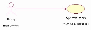
Figure 6 - Editor Use Cases
Significant Use Case Descriptions
- Approve Story
This Use Case takes place when an editor approves a story for inclusion in the Collegiate Sports Paging System. Some stories will automatically propogate from the existing WebNewsOnLine system, but some stories will require editor intervention (either because their subject is not clear or the categories to which the story belongs are not clear). This flow is also used to approve advertising content being posted.
- Edit Profile
This Use Case occurs when a subscriber wishes to change their profile information or when a new subscriber wishes to enroll.
- Pay Fee With Credit Card
This use case occurs when a new subscriber wants to pay their annual subscription fee by specifying a credit card number and PIN. This may also occur when an existing subscriber wants to renew.
- Print Advertiser Reports
This use case occurs when an advertiser accesses the Collegiate Sports Paging System to obtain reports of how their advertising content has been viewed. Advertiser selects format (Microsoft® Word®, Microsoft® Excel®, or HTML) for the report.
- Provide Feedback
This use case occurs when a system user (advertiser, subscriber, or potential subscriber) wishes to comment on the service or the web site.
- Post Advertising Content
This use case occurs when an advertiser wants to post advertising content (banner ads) on the web site and specify which subscriber profiles should be used for display.
- Read Content on Web Site
This use case occurs when an active subscriber connects to the system to view targeted information. Pages are dynamically built to show the user headlines for which they have been paged, as well as general sports categories to which they subscribe.
- Send Content
This use case occurs when content is posted to the existing WebNewsOnLine website. Some stories will be tagged for transmission to the Collegiate Sports Paging System, and will be sent for possible paging and display.
- Send Page
This use case occurs when new content is posted to the Collegiate Sports Paging System. This includes finding subscribers to be notified, formatting the page message, and sending the page via email.
- Subscribe
This use case occurs when a potential subscriber wants to subscribe to the service. It notifies the user of contract terms and, if accepted, invokes the use case to edit a profile (specifying categories to which the user wants to subscribe, pager information, credit card info, etc.).
Logical View
Overview
A description of the logical view of the architecture. Describes the most important classes, their organization in service packages and subsystems, and the organization of these subsystems into layers. Also describes the most important use-case realizations, for example, the dynamic aspects of the architecture. Class diagrams may be included to illustrate the relationships between architecturally significant classes, subsystems, packages and layers.
The logical view of the Collegiate Sports Paging System is comprised of 5 main packages:
- Presentation
- contains classes for each of the forms that the actors use to communicate with the System. Boundary classes exist to support maintaining of profiles, posting of advertising, printing of advertising reports, approving stories, providing feedback, subscribing, and paying fees with credit cards
- Application
- contains classes for major processing functionality within the system. Control classes exist to support advertising administration, content management, profile management, subscription processing, paying fees with credit cards, and providing feedback.
- Domain
- contains packages containing classes to support Content, Profile, Subscription, and Support.
- Persistence
- contains classes to persist specific objects within the system. At this point in the design, only Profiles are persisted, though Content objects may be persisted at some future point (a selection of a packaged content management system may obviate the need for this).
- Services
- contains classes to provide system-level classes for maintenance purposes - at this time, all maintenance is manual.
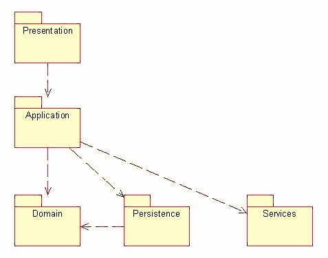
Logical View
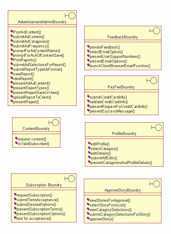
Presentation Package
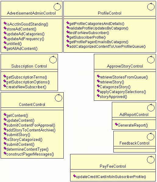
Application Package
Domain Package
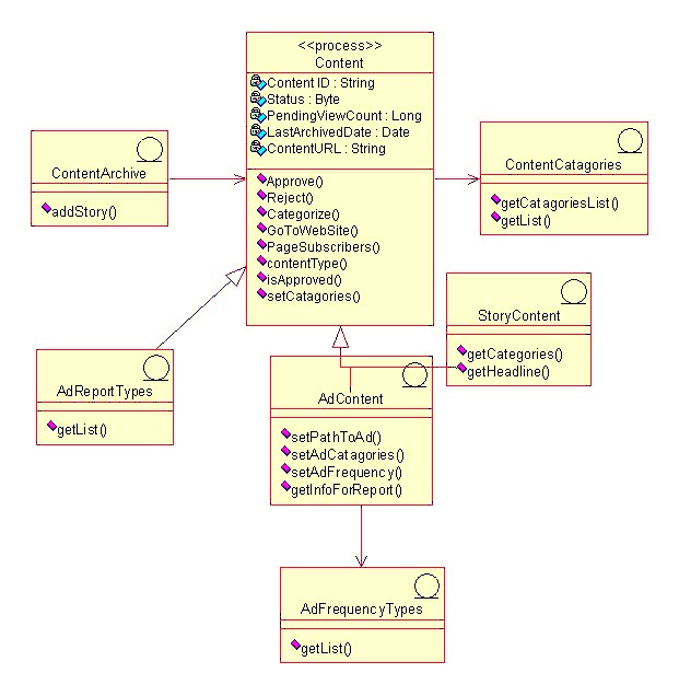
Content Package

Profile Package
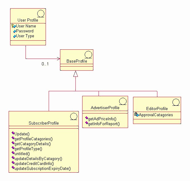
Subscribe Package
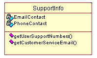
Support Package
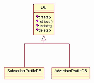
Persistence Package
Process View
This section describes the system’s decomposition into lightweight processes (single threads of control) and heavyweight processes (groupings of lightweight processes). Organize the section by groups of processes that communicate or interact. Describe the main modes of communication between processes, such as message passing, interrupts, and rendezvous.
At this point in the design, a single process is envisioned to provide server-level functions for the Collegiate Sports Paging System. Threads for application functions will be part of this process (application functions are listed in the previous section). The process diagram of the system can be viewed as follows:
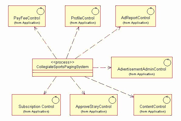
Deployment View
This section describes one or more physical network (hardware) configurations on which the software is deployed and run. At a minimum for each configuration it should indicate the physical nodes (computers, CPUs) that execute the software, and their interconnections (bus, LAN, point-to-point, and so on.) Also include a mapping of the processes of the Process View onto the physical nodes.
The CSPS Server is a UNIX server. The Client machine is any device capable of running a Web browser (most likely a PC, but not necessarily) and of connecting to the CSPS via the Internet. The Pager Gateway is an externally-maintained device provided by paging services.
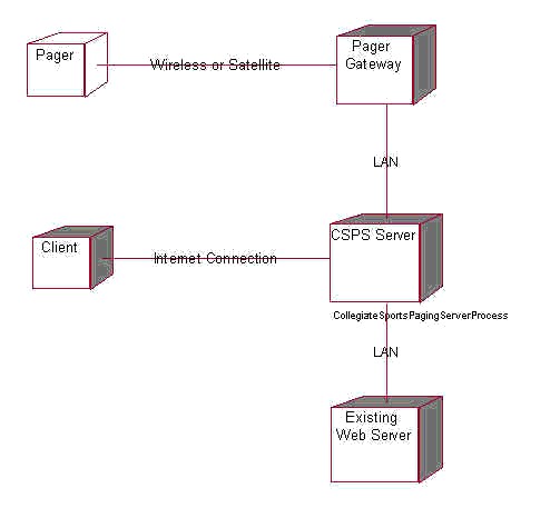
Implementation View
All server software resides within a single layer. The browser client provides a secondary access layer.
Size and Performance
The software as designed will support 200,000 concurrent users. Scaling beyond this level may be achieved by providing multiple levels of Pager Gateway, or by simply providing additional Pager Gateway systems within the same tier.
Quality
The software as described above supports the existing WebNewsOnLine graphical standards, interfaces with the existing WebNewsOnLine server, and provides a self-describing user interface.
CSPS Software Development Plan
The Elaboration Phase will analyze the requirements and will develop the architectural prototype. At the completion of the Elaboration Phase all use cases selected for Release 1.0 will have completed analysis and design. In addition, the high risk use cases for Release 2.0 will have been analyzed and designed. The architectural prototype will test the feasibility and performance of the architecture that is required for Release 1.0. The Architectural Prototype Milestone marks the end of the Elaboration Phase. This prototype signifies verification of the major architectural components that comprise the R1.0 Release.
CSPS Status Assessment 12.22.99
**Collegiate Sports Paging System
Status Assessment
Version 1.0**
Revision History
| Date | Version | Description | Author |
| November 22, 1999 | 1.0 | Weekly assessment | Context Integration |
Table of Contents
- Introduction
- Resources
- [Top 10 Risks](#Top 10 Risks)
- [Technical Progress](#Technical Progress)
- [Major Milestone Results](#Major Milestone Results)
- [Total Project/Product Scope](#Total Project/Product Scope)
- [Action Items and Follow-Through](#Action Items and Follow-Through)
Introduction
Purpose
This status assessment reviews the current status of the project with respect to resources, budget, schedule, risk, technical issues, and management issues. Any actions arising from this assessment will be summarized in this document.
Scope
This assessment reviews all aspects of the Collegiate Sports Paging System.
Definitions, Acronyms and Abbreviations
See Glossary.
References
- CSPS Vision 1.0
- CSPS Requirements Management Plan 1.0
- CSPS Iteration Plan 1.0
- CSPS Creative Design Brief 1.0
- CSPS Supplementary Specification 1.0
- CSPS Iteration Plan 3.0
- CSPS Risk List 3.0
Resources
Personnel/Staffing
Elaboration staff will be leaving the project as they are no longer needed. Departing staff include Brian Egler, Business Analyst, and Mark Grimes, Creative Designer. Staff whose contribution will increase are Justin Woddis, Implementer, various implementation subcontractors reporting to Justin, and Chris Curvey, Tester.
Financial Data
The project is delivered on a fixed-price basis. As such, no financial data need be reported.
Top 10 Risks
The project risks and their mitigation strategies can be found in the Risk List.
Technical Progress
During this iteration, the following artifacts were produced:
- User-Interface Prototype
- Analysis Model
- Design Model
- Software Architecture Document
- Integration Build Plan
- Architectural Prototype - Software Baseline
- Test Drivers, Stubs, Data, & Scripts
- Test Procedures
- Test Evaluation Report
- Iteration Plan
- Status Assessment
- Iteration Assessment
- Test Plan
- Design Guidelines
- User-Interface Guidelines
The following artifacts were updated:
- Glossary
- Vision Document
- Use Case Specifications
- Supplementary Specification
- Use Case Model and Model Survey
- Project Plan
- Project Schedule
- Project Risk List
Major Milestone Results
The following table lists iteration milestones and their status at the end of this iteration.
| Milestone | Planned | Actual | Comments |
| Use case design complete | 11/3/1999 | 11/4/1999 | One-day slip for documentation |
| Software Architecture document complete | 11/22/1999 | 11/21/1999 | No major issues raised with use cases during architectural design |
| Test Plans Complete | 11/9/1999 | 11/10/1999 | Mapped to use cases |
Total Project/Product Scope
No scope changes occurred during this period.
Action Items and Follow-Through
The following action items were carried forward from last week or initiated this week:
| Item | Assigned | Due | Status |
| Validate color scheme for UI with advertiser rep. | Mark Grimes | 11/19/1999 | Closed - minor change made to UI design guidelines |
| Investigate multi-tiered gateway approach | Ken Perch | 11/25/1999 | Open |
CSPS Supplementary Specification(补充规约) 1.0
**Collegiate Sports Paging System
Supplementary Specification**
Version 1.0
Revision History
| Date | Version | Description | Author |
| October 10, 1999 | 1.0 | Initial version | Context Integration |
Table of Contents
- Introduction
- Functionality
- Usability
- Reliability
- Performance
- Supportability
- [Design Constraints](#Design Constraints)
- [Online User Documentation and Help System Requirements](#Online User Documentation and Help System Requirements)
- [Purchased Components](#Purchased Components)
- Interfaces
- [Licensing Requirements](#Licensing Requirements)
- [Legal, Copyright, and Other Notices](#Legal, Copyright, and Other Notices)
- [Applicable Standards](#Applicable Standards)
Introduction
Purpose
The purpose of this document is to define requirements of the Collegiate Sports Paging System. This Supplementary Specification lists the requirements that are not readily captured in the use cases of the use-case model. The Supplementary Specifications and the use-case model together capture a complete set of requirements on the system.
Scope
This Supplementary Specification applies to the Collegiate Sports Paging System which will be developed by Context Integration.
The Collegiate Sports Paging System will allow subscribers to be notified via alphanumeric pager (or cellular phone or email) of events in specific areas of interest, then to access content via an individualized web interface.
This specification defines the non-functional requirements of the system; such as reliability, usability, performance, and supportability as well as functional requirements that are common across a number of use cases. (The functional requirements are defined in the Use Case Specifications.)
Definitions, Acronyms and Abbreviations
See Glossary.
References
Functionality
Functional requirements are captured via the defined use cases.
Usability
Ease of use
The system will not require user training beyond that of using a web browser. This will be verified by usability tests during the beta period.
Reliability
Availability
To be defined in subsequent phases.
Performance
Subscriber volume
The system will be able to support 200,000 subscribers, and provide a scaling mechanism to handle 500,000 subscribers.
Paging latency
When a news story is posted to the system, pages must be transmitted to the pager gateway within 5 minutes.
Supportability
Subscriber software
The subscriber shall be able to utilize the system through commercially available browser software. No custom software will be required to reside on the subscriber’s PC.
Design Constraints
WebNewsOnLine Look and Feel
: The system shall conform with existing WebNewsOnLine web site design standards.
WebNewsOnLine existing system connection
: The system shall communicate with the existing WebNewsOnLine web site for the purpose of receiving story content.
Online User Documentation and Help System Requirements
Each major function provided by the system will have its own online help function.
Purchased Components
To be defined in subsequent phases.
Interfaces
User Interfaces
See Creative Design documents:
Hardware Interfaces
To be defined in subsequent phases.
Software Interfaces
To be defined in subsequent phases.
Communications Interfaces
To be defined in subsequent phases.
Licensing Requirements
No client licenses are required.
Legal, Copyright, and Other Notices
Copyright statements indicating content ownership shall be included in content as required by policy.
Applicable Standards
To be defined in subsequent phases.
CSPS Supplementary Specification 2.0
**Collegiate Sports Paging System
Supplementary Specification**
Version 2.0
Revision History
| Date | Version | Description | Author |
| October 10, 1999 | 1.0 | Initial version | Context Integration |
| December 2, 1999 | 2.0 | Update following Elaboration phase | Context Integration |
Table of Contents
- Introduction
- Functionality
- Usability
- Reliability
- Performance
- Supportability
- [Design Constraints](#Design Constraints)
- [Online User Documentation and Help System Requirements](#Online User Documentation and Help System Requirements)
- [Purchased Components](#Purchased Components)
- Interfaces
- [Licensing Requirements](#Licensing Requirements)
- [Legal, Copyright, and Other Notices](#Legal, Copyright, and Other Notices)
- [Applicable Standards](#Applicable Standards)
Introduction
Purpose
The purpose of this document is to define requirements of the Collegiate Sports Paging System. This Supplementary Specification lists the requirements that are not readily captured in the use cases of the use-case model. The Supplementary Specifications and the use-case model together capture a complete set of requirements on the system.
Scope
This Supplementary Specification applies to the Collegiate Sports Paging System which will be developed by Context Integration.
The Collegiate Sports Paging System will allow subscribers to be notified via alphanumeric pager (or cellular phone or email) of events in specific areas of interest, then to access content via an individualized web interface.
This specification defines the non-functional requirements of the system; such as reliability, usability, performance, and supportability as well as functional requirements that are common across a number of use cases. (The functional requirements are defined in the Use Case Specifications.)
Definitions, Acronyms and Abbreviations
See Glossary.
References
- CSPS Vision 1.0
- CSPS Requirements Management Plan 1.0
- CSPS Creative Design Brief 1.0
- CSPS Design Comps 1.0
Functionality
Functional requirements are captured via the defined use cases.
Usability
Ease of use
The system will not require user training beyond that of using a web browser. This will be verified by usability tests during the beta period.
Reliability
Availability
The system will be available 24 hours per day, 7 days per week.
Performance
Subscriber volume
The system will be able to support 200,000 subscribers, and provide a scaling mechanism to handle 500,000 subscribers.
Paging latency
When a news story is posted to the system, pages must be transmitted to the pager gateway within 5 minutes.
Supportability
Subscriber software
The subscriber shall be able to utilize the system through commercially available browser software. No custom software will be required to reside on the subscriber’s PC.
Design Constraints
WebNewsOnLine Look and Feel
The system shall conform with existing WebNewsOnLine web site design standards.
WebNewsOnLine existing system connection
The system shall communicate with the existing WebNewsOnLine web site for the purpose of receiving story content.
Online User Documentation and Help System Requirements
Each major function provided by the system will have its own online help function.
Purchased Components
None.
Interfaces
User Interfaces
See Creative Design documents (references 4, 5, and 6).
Hardware Interfaces
No custom hardware interfaces are required.
Software Interfaces
The system will interconnect with the existing WebNewsOnLine system to receive content.
Communications Interfaces
The system requires no custom communications interfaces.
Licensing Requirements
No client licenses are required.
Legal, Copyright, and Other Notices
Copyright statements indicating content ownership shall be included in content as required by policy.
Applicable Standards
To be defined in subsequent phases.
CSPS Test Evaluation Report 1.0
**Collegiate Sports Paging System
Test Evaluation Summary
Version 1.0**
Revision History
| Date | Version | Description | Author |
| November 17, 1999 | 1.0 | Initial version | Context Integration |
Table of Contents
- Introduction
- [Test Results Summary](#Test Results Summary)
- [Test Coverage](#Test Coverage)
- [Code Coverage](#Code Coverage)
- [Suggested Actions](#Suggested Actions)
- Diagrams
Introduction
Purpose
This Test Evaluation Report describes the results of the tests in terms of test coverage (both requirements-based and code-based coverage) and defect analysis (i.e. defect density).
Scope
This Test Evaluation Report applies to the first Construction Iteration of the project. The tests conducted are described in the Test Plan for the first Construction Iteration. This Evaluation Report is to be used for the following:
- assess the acceptability and appropriateness of the performance behavior(s) of the prototype,
- assess the acceptability of the tests, and
- identify improvements to increase test coverage and / or test quality.
Definitions, Acronyms and Abbreviations
See Glossary.
References
Test Results Summary
The test cases defined in the Test Model were executed following the test strategy as defined in the Test Plan. The test defects have been logged and any medium, high, or critical priority defects are currently assigned to the owner for fixing.
Test coverage (see the Test Coverage section in this document) in terms of covering the use cases and test requirements defined in the Test Plan was 100% complete.
Code coverage was measured using Rational Visual PureCoverage and is described in the Code Coverage section in this document.
Analysis of the defects (as shown in the Diagrams section in this document) indicates that the majority of found defects tend to be minor problems classified as low or medium in severity. The other significant finding was that software components comprising the interface to the Pager Gateway contained the highest number of defects.
Test Coverage
All test cases not relating to advertising content, as defined in the Test Model, were attempted. Of the tests cases executed, 5 tests failed.
The test coverage results are as follows:
- Ratio Test Cases Performed = 80/80= 100%
- Ratio Test Cases Successful = 75/80 = 93.75%
The area of tests with the highest failure rate was the Pager Gateway Interface, which failed under high volume testing.
Further detail on test coverage is available using Rational RequisitePro and the Test Case matrix.
Code Coverage
Rational Visual PureCoverage was used to measure code coverage of the tests.
Ratio LOC executed = 94,399 / 102,000 = 93%
Approximately, 93% of the code was executed during the testing. This coverage exceeded the target of 90%.
Suggested Actions
The following actions are recommended to improve performance to an acceptable level:
- Implement a multi-tiered Pager Gateway system to provide increased scalability. This will require additional hardware to be installed by WebNewsOnLine.
Diagrams
CSPS Test Plan 1.0
Collegiate Sports Paging System
Test Plan
Version 1.0
Revision History
| Date | Version | Description | Author |
| October 26, 1999 | 1.0 | Initial version | Context Integration |
Table of Contents
- Introduction
- [Requirements for Test](#Requirements for Test)
- [Test Strategy](#Test Strategy)
- Resources
- [Project Milestones](#Project Milestones)
- Deliverables
- [Appendix A: Project Tasks](#Appendix A: Project Tasks)
Introduction
Purpose
This Test Plan document for the Collegiate Sports Paging System supports the following objectives:
- Identify existing project information and the software components that should be tested
- List the recommended Requirements for Test (high level)
- Recommend and describe the testing strategies to be employed
- Identify the required resources and provide an estimate of the test efforts
- List the deliverable elements of the test project
Background
The Collegiate Sports Paging System provides alphanumeric paging to subscribers when events occur within collegiate sports categories to which they subscribe. Subscribers can then connect to a personalized web site where they can view the stories for which they were paged, as well as other collegiate sports news.
The system is comprised of 3 major subsystems contained on an Application Web Server and interacts with the existing WebNewsOnLine web site as well as paging gateways. The subsystems include:
- Content management - this subsystem accepts content, marks categories, and displays headlines for subscribers. It also manages advertising content that is targeted to specific groups of subscribers (based on their subscription profiles).
- Paging - this subsystem activates when new content is loaded onto the system. It is responsible for determining who should be paged and sending messages to the paging gateways.
- Reporting - this subsystem tracks and reports on advertising viewing.
The system architecture can be depicted as follows:
Scope
The Collegiate Sports Paging System will be unit tested and system tested. Unit tests will address functional quality, while system testing will address issues of scalability and performance.
The interaction of the subsystems will be tested as follows:
- Content Management to Paging
- Content Management to Reporting
The following systems interfaces will be tested:
- Collegiate Sports Paging System to existing WebNewsOnLine Web Server
- Collegiate Sports Paging System to paging gateways
The most critical testing will be that of load and performance testing. This will be addressed as follows:
- We will create a test scenario that will generate increasing numbers of pages up to 200,000.
- We will also create a test scenario that has new content arriving at the system at the rate of one item every 20 seconds.
- Lastly, we will simulate increasing concurrent subscriber loads up to 200,000.
Project Identification
The table below identifies the documentation and availability, used for developing the test plan:
| Document (and version / date) | Created or Available | Received or Reviewed | Author or Resource | Notes |
| Vision Document | n Yes o No | n Yes o No | Context Integration | |
| Supplemental Specification | n Yes o No | n Yes o No | Context Integration | |
| Use Case Reports | n Yes o No | n Yes o No | Context Integration | |
| Project Plan | n Yes o No | n Yes o No | Context Integration | |
| Design Specifications | o Yes n No | o Yes o No | ||
| Prototype | n Yes o No | n Yes o No | Context Integration | |
| Project / Business Risk Assessment | n Yes o No | n Yes o No | Context Integration |
Requirements for Test
The listing below identifies those items (use cases, functional requirements, non-functional requirements) that have been identified as targets for testing. This list represents what will be tested.
Database Testing
Verify that subscriber information can be entered and retrieved.
Verify that content and categories can be inserted and displayed.
Verify that advertiser profiles and account information can be entered and displayed.
Verify that subscriber-specific usage information is tracked.
Functional Testing
Verify that subscribers see the information for which they have requested paging.
Verify that pages go to subscribers when content arrives.
Verify that automatic content insertion works.
Verify that editor approval causes non-automatic content to be inserted.
Verify that subscribers who have lapsed subscriptions do not receive pages.
Verify that content marked as archived is not re-displayed to subscribers.
Verify that obsolete content is deleted.
Verify that advertiser reports are accurate.
Verify that advertiser reports can be received in Microsoft® Word®, Microsoft® Excel ®, or HTML.
Business Cycle Testing
None.
User Interface Testing
Navigate through all use cases, verifying that each UI panel can be easily understood
Verify all online Help functions
Verify that all screens conform to the WebNewsOnLine standards.
Performance Profiling
Verify response time of interface to Pager Gateway system.
Verify response time of interface from existing WebNewsOnLine web server.
Verify response time when connected using 56Kbps modem.
Verify response time when connected locally (on the same LAN).
Load Testing
Verify system response with 200 concurrent subscribers.
Verify system response with 500 concurrent subscribers.
Verify system response with 1,000 concurrent subscribers.
Verify system response with 5,000 concurrent subscribers.
Verify system response with 10,000 concurrent subscribers.
Verify system response with 50,000 concurrent subscribers.
Verify system response with 100,000 concurrent subscribers.
Verify system response with 200,000 concurrent subscribers.
Stress Testing
None.
Volume Testing
Verify pages sent out within 5 minutes when single content element arrives.
Verify pages sent out within 5 minutes when content arrives every 20 seconds.
Security and Access Control Testing
Verify that non-subscribers cannot access subscriber-only information.
Verify that non-editors can not approve content.
Verify that advertisers see only their own advertising content.
Failover/Recovery Testing
None.
Configuration Testing
Verify operation using Netscape V4.x browser.
Verify operation using Microsoft® Internet Explorer® V5.x
Installation Testing
None.
Test Strategy
Testing Types
Data and Database Integrity Testing
| Test Objective: | Ensure database access methods and processes function properly and without data corruption. |
| Technique: | - Invoke each database access method and process, seeding each with valid and invalid data (or requests for data). - Inspect the database to ensure the data has been populated as intended, all database events occurred properly, or review the returned data to ensure that the correct data was retrieved (for the correct reasons) |
| Completion Criteria: | All database access methods and processes function as designed and without any data corruption. |
| Special Considerations: | - Processes should be invoked manually. - Small or minimally sized databases (limited number of records) should be used to increase the visibility of any non-acceptable events. |
Function Testing
| Test Objective: | Ensure proper target-of-test functionality, including navigation, data entry, processing, and retrieval. |
| Technique: | Execute each use case, use case flow, or function, using valid and invalid data, to verify the following: - The expected results occur when valid data is used. - The appropriate error and warning messages are displayed when invalid data is used. - Each business rule is properly applied. |
| Completion Criteria: | - All planned tests have been executed. - All identified defects have been addressed. |
| Special Considerations: | None. |
User Interface Testing
| Test Objective: | Verify the following: - Navigation through the target-of-test properly reflects business functions and requirements, including window to window, field to field, and use of access methods (tab keys, mouse movements, accelerator keys) - Web objects and characteristics, such as menus, size, position, state, and focus conform to standards. |
| Technique: | Create or modify tests for each window to verify proper navigation and object states for each application window and objects. |
| Completion Criteria: | Each window successfully verified to remain consistent with benchmark version or within acceptable standard |
| Special Considerations: | Not all properties for custom and third party objects can be accessed. |
Performance Profiling
| Test Objective: | Verify performance behaviors for designated transactions or business functions under the following conditions: - normal anticipated workload - anticipated worse case workload |
| Technique: | Use Test Procedures developed for Function or Business Cycle Testing. Modify data files (to increase the number of transactions) or the scripts to increase the number of iterations each transaction occurs. Scripts should be run on one machine (best case to benchmark single user, single transaction) and be repeated with multiple clients (virtual or actual, see special considerations below). |
| Completion Criteria: | Single Transaction or single user: Successful completion of the test scripts without any failures and within the expected or required time allocation (per transaction) Multiple transactions or multiple users: Successful completion of the test scripts without any failures and within acceptable time allocation. |
| Special Considerations: | Comprehensive performance testing includes having a “background” workload on the server. There are several methods that can be used to perform this, including: - “Drive transactions” directly to the server, usually in the form of SQL calls. - Create “virtual” user load to simulate many (usually several hundred) clients. Remote Terminal Emulation tools are used to accomplish this load. This technique can also be used to load the network with “traffic.” - Use multiple physical clients, each running test scripts to place a load on the system. Performance testing should be performed on a dedicated machine or at a dedicated time. This permits full control and accurate measurement. The databases used for Performance testing should be either actual size, or scaled equally. |
Load Testing
| Test Objective: | Verify performance behaviours time for designated transactions or business cases under varying workload conditions. |
| Technique: | Use tests developed for Function or Business Cycle Testing. Modify data files (to increase the number of transactions) or the tests to increase the number of times each transaction occurs. |
| Completion Criteria: | Multiple transactions or multiple users: Successful completion of the tests without any failures and within acceptable time allocation. |
| Special Considerations: | Load testing should be performed on a dedicated machine or at a dedicated time. This permits full control and accurate measurement. The databases used for load testing should be either actual size, or scaled equally. |
Volume Testing
| Test Objective: | Verify that the target-of-test successfully functions under the following high volume scenarios: - maximum (actual or physically capable) number of clients connected (or simulated) all performing the same, worst case (performance) business function for an extended period. - maximum database size has been reached (actual or scaled) and multiple queries and report transactions are executed simultaneously. |
| Technique: | Use tests developed for Performance Profiling or Load Testing. Multiple clients should be used, either running the same tests or complementary tests, to produce the worst case transaction volume or mix (see stress test above) for an extended period. Maximum database size is created (actual, scaled, or filled with representative data) and multiple clients used to run queries and report transactions simultaneously for extended periods. |
| Completion Criteria: | All planned tests have been executed and specified system limits are reached or exceeded without the software or software failing. |
| Special Considerations: | What period of time would be considered an acceptable time for high volume conditions (as noted above)? |
Security and Access Control Testing
| Test Objective: | Application-level Security: Verify that an actor can access only those functions and data for which their user type is provided permissions. System-level Security: Verify that only those actors with access to the system and applications are permitted to access them. |
| Technique: | Application-level: Identify and list each actor type and the functions or data each type has permissions for. Create tests for each actor type and verify each permission by creating transactions specific to each user actor. Modify user type and re-run tests for same users. In each case verify those additional functions and data are correctly available or denied. System-level Access (see special considerations below) |
| Completion Criteria: | For each known actor type, the appropriate function and data are available, and all transactions function as expected and run in prior function tests |
| Special Considerations: | Access to the system must be reviewed or discussed with the appropriate network or systems administrator. This testing may not be required as it maybe a function of network or systems administration. |
Configuration Testing
| Test Objective: | Verify that the target-of-test functions properly on the required hardware and software configurations. |
| Technique: | Use Function Test scripts Open or close various non-target-of-test related software, such as the Microsoft applications Excel® and Word®, either as part of the test or prior to the start of the test. Execute selected transactions to simulate actor’s interacting with the target-of-test and the non-target-of-test software Repeat the above process, minimizing the available conventional memory on the client. |
| Completion Criteria: | For each combination of the target-of-test and non-target-of-test software, all transactions are successfully completed without failure. |
| Special Considerations: | What non-target-of-test software is needed, is available, accessible on the desktop? What applications are typically used? What data are the applications running (that is, large spreadsheet opened in Excel, 100 page document in Word)? The entire systems, netware, network servers, databases, and so forth should also be documented as part of this test. |
Tools
The following tools will be employed for this project:
| Tool | Version | |
| Defect Tracking | Project HomePage | |
| Project Management | Microsoft® Project® |
Resources
This section presents the recommended resources for the Collegiate Sports Paging System test effort, their main responsibilities, and their knowledge or skill set.
Workers
This table shows the staffing assumptions for the project.
| Human Resources | ||
| Worker | Minimum Resources Recommended | Specific Responsibilities and Comments |
| Test Manager, Test Project Manager | 1 ( Collegiate Sports Paging System project manager) | Provides management oversight Responsibilities: - Provide technical direction - Acquire appropriate resources - Management reporting |
| Test Designer | 1 | Identifies, prioritizes, and implements test cases Responsibilities: - Generate test plan - Generate test model - Evaluate effectiveness of test effort |
| Tester | 4 (provided by WebNewsOnLine) | Executes the tests Responsibilities: - Execute tests - Log results - Recover from errors - Document change requests |
| Test System Administrator | 1 | Ensures test environment and assets are managed and maintained. Responsibilities: - Administer test management system - Install and manage worker access to test systems |
| Database Administration / Database Manager | 1 (provided by WebNewsOnLine) | Ensures test data (database) environment and assets are managed and maintained. Responsibilities: - Administer test data (database) |
| Designer | 2 | Identifies and defines the operations, attributes, and associations of the test classes Responsibilities: - Identifies and defines the test class(es) - Identifies and defines the test packages |
| Implementer | 4 | Implements and unit tests the test classes and test packages Responsibilities: - Creates the test classes and packages implemented in the test model. |
System
The following table sets forth the system resources for the testing project.
The specific elements of the test system are not fully known at this time. It is recommended that the system simulate the production environment, scaling down the accesses and database sizes, if and where appropriate.
| System Resources | |
| Resource | Name and Type |
| Database Server | |
| -Network/Subnet | TBD |
| -Server Name | TBD |
| -Database Name | TBD |
| Client Test PCs | |
| -Include special configuration -requirements | TBD |
| Test Repository | |
| -Network/Subnet | TBD |
| -Server Name | TBD |
| Test Development PCs | TBD |
Project Milestones
| Milestone Task | Effort | Start Date | End Date | ||
| Plan Test | |||||
| Design Test | |||||
| Implement Test | |||||
| Execute Test | |||||
| Evaluate Test |
Deliverables
Test Model
For each test executed, a test result form will be created. This will include the name or ID of the test, the use case or supplemental specification to which the test relates, the date of the test, the ID of the tester, required pre-test conditions, and results of the test.
Test Logs
Microsoft Word will be used to record and report test results.
Defect Reports
Defects will be recorded using the Project HomePage using the Web.
Appendix A: Project Tasks
The following table lists the test related tasks.
CSPS Use Case : Approve Story 1.0
**Collegiate Sports Paging System
Use Case Specification: Approve Story**
Version 1.0
Revision History
| Date | Version | Description | Author |
| October 9, 1999 | 1.0 | Initial version | Context Integration |
Table of Contents
- [Approve Story](#Approve Story)
- [Flow of Events](#Flow of Events)
- [Special Requirements](#Special Requirements)
- Preconditions
- Postconditions
- [Extension Points](#Extension Points)
Approve Story
Brief Description
This Use Case takes place when an editor approves a story for inclusion in the Collegiate Sports Paging System. Some stories will automatically propogate from the existing system, but some stories will require editor intervention (either because their subject is not clear or the categories to which the story belongs are not clear). This flow is also used to approve advertising content being posted.
Flow of Events
Basic Flow
- The system places a story in the editor’s “to-do” workflow.
- The editor views the story.
- The editor categorizes the story and marks it approved.
- The system includes the story and triggers initiation of paging messages.
Alternate Flows
-
Reject Content
-
The editor views the story.
-
The editor marks the story as rejected
-
The system notifies the originator of the content that the story has been rejected
-
Modify Content
-
Editor selects “Modify Story”
-
System displays titles of all stories available
-
Editor selects specific title
-
System displays characteristics of story
-
Editor updates characteristics
-
Editor selects “Save”
-
System re-posts story, triggering paging activity as needed
-
Approve Advertising Content
-
The editor views the advertising content
-
The editor marks it approved.
-
The system includes the advertising content for display
-
The system marks the preliminary billing record as approved
-
Reject Advertising Content
-
The editor views the advertising content
-
The editor marks it rejected and provides a reason for rejection
-
The system notifies the advertiser (via email) of the rejection and the reason
-
Story not viewable
If the story has been deleted by another editor and is not currently viewable, the use case terminates.
Special Requirements
Special requirements will be determined during the next iteration.
Preconditions
Editor must be logged in.
Postconditions
Postconditions will be determined during the next iteration.
Extension Points
Extension points of the use case will be identified during the Elaboration Phase.
CSPS Use Case : Approve Story 2.0
**Collegiate Sports Paging System
Use Case Specification: Approve Story**
Version 2.0
Revision History
| Date | Version | Description | Author |
| October 9, 1999 | 1.0 | Initial version | Context Integration |
| December 1, 1999 | 2.0 | Update with detail from Elaboration | Context Integration |
Table of Contents
- [Approve Story](#Approve Story)
- [Flow of Events](#Flow of Events)
- [Special Requirements](#Special Requirements)
- Preconditions
- Postconditions
- [Extension Points](#Extension Points)
Approve Story
Brief Description
This Use Case takes place when an editor approves a story for inclusion in the Collegiate Sports Paging System. Some stories will automatically propogate from the existing system, but some stories will require editor intervention (either because their subject is not clear or the categories to which the story belongs are not clear). This flow is also used to approve advertising content being posted.
Flow of Events
Basic Flow
- The system places a story in the editor’s “to-do” workflow queue. If more than one editor is defined, a round-robin approach is used to attempt to balance load. Editors may be marked as unavailable (if, for instance, they are on vacation or sick or out of the office), in which case they will not be included in the round-robin process.
- The editor views the story.
- The editor categorizes the story by selecting from system-provided categories. There may be more than one category assigned to the story. At least one category must be assigned to the story.
- The editor then marks the story as approved.
- The system includes the story in the list of available content for paging initiation.
- The system triggers initiation of paging messages.
Alternate Flows
-
Reject Content
-
The editor views the story.
-
The editor marks the story as rejected and describes the reason for rejection.
-
The system notifies the originator of the content that the story has been rejected and includes the reason provided by the editor.
-
The system deletes the story.
-
Modify Content
-
Editor selects “Modify Story”
-
System displays titles of all stories available
-
Editor selects specific title
-
System displays characteristics of story
-
Editor updates characteristics, either deleting some categories, adding other categories, or both.
-
Editor selects “Save”
-
System re-posts the story to the list of available content for paging initiation.
-
The system triggers initiation of paging messages.
-
Approve Advertising Content
-
The editor views the advertising content
-
The editor marks it approved.
-
The system includes the advertising content in the list of available advertising for display
-
The system creates a preliminary billing record, using information stored about the advertiser (billing rate indicator, advertiser name and billing address), content identification, date, and total due.
-
The system marks the preliminary billing record as approved
-
Reject Advertising Content
-
The editor views the advertising content
-
The editor marks it rejected and provides a reason for rejection. This may include account overdue, content inappropriate or not within scope of contract, or duplicate content (advertising content is already on file and being displayed).
-
The system notifies the advertiser (via email) of the rejection and the reason.
-
The system deletes the content.
-
Story not viewable
If the story has been deleted by another editor and is not currently viewable, the use case terminates.
Special Requirements
None.
Preconditions
Editor must be logged in.
Postconditions
When this use case is complete, content is available. For advertising content, the content will be eligible for display immediately. For story content, the paging process can begin immediately.
Extension Points
None.
CSPS Use Case : Edit Profile 1.0
**Collegiate Sports Paging System
Use Case Specification: Edit Profile**
Version 1.0
Revision History
| Date | Version | Description | Author |
| October 9, 1999 | 1.0 | Initial version | Context Integration |
Table of Contents
- [Edit Profile](#Edit Profile)
- [Flow of Events](#Flow of Events)
- [Special Requirements](#Special Requirements)
- Preconditions
- Postconditions
- [Extension Points](#Extension Points)
Edit Profile
Brief Description
This use case occurs when a subscriber wishes to change their profile information or when a new subscriber wishes to enroll.
Flow of Events
Basic Flow
- User selects “Edit Profile”
- System displays categories of profile (personal, preferences, pager information, “page me when” selections).
- User selects category
- System displays detail
- User updates detail, presses “OK”
- System validates data as required, updates subscriber profile.
Alternate Flows
If this is a new subscriber, the use case “Pay Fee with Credit Card” is invoked following step 5 above.
Special Requirements
Special requirements will be determined during the next iteration.
This needs to be secured as credit card information may be in the profile.
Preconditions
Preconditions will be determined during the next iteration.
Postconditions
Postconditions will be determined during the next iteration.
Extension Points
Extension points of the use case will be identified during the Elaboration Phase.
CSPS Use Case : Edit Profile 2.0
**Collegiate Sports Paging System
Use Case Specification: Edit Profile**
Version 2.0
Revision History
| Date | Version | Description | Author |
| October 9, 1999 | 1.0 | Initial version | Context Integration |
| December 1, 1999 | 2.0 | Update after Elaboration phase | Context Integration |
Table of Contents
- [Edit Profile](#Edit Profile)
- [Flow of Events](#Flow of Events)
- [Special Requirements](#Special Requirements)
- Preconditions
- Postconditions
- [Extension Points](#Extension Points)
Edit Profile
Brief Description
This use case occurs when a subscriber wishes to change their profile information or when a new subscriber wishes to enroll.
Flow of Events
Basic Flow
- User selects “Edit Profile”
- System displays categories of profile ([personal](ex_gloss2.md#Personal Profile), [preferences](ex_gloss2.md#Preferences Profile), pager information, “[page me when](ex_gloss2.md#Page-me-when Profile)” selections).
- User selects category.
- If more than one profile exists for a category (for instance, a subscriber may have more than one pager), a list of possible profiles within the category is presented.
- User selects specific profile within category.
- System displays detail of specific profile.
- User updates detail, presses “OK”
- If information changed includes credit card information, system validates new information with external credit card system. If information contains pager information, pager PIN format is validated along with email address for sending pages.
- System updates subscriber profile.
Alternate Flows
If validation of credit card information fails, user is presented with a message indicating failure, and is presented with their profile for update once again.
If this is a new subscriber, the use case “Pay Fee with Credit Card” is invoked following step 9 above.
Special Requirements
This needs to be secured as credit card information may be in the profile.
Preconditions
None.
Postconditions
For a new subscriber, when this use case is complete, the subscriber is immediately eligible to receive pages.
Extension Points
None.
CSPS Use Case : Pay Fee with Credit Card 1.0
**Collegiate Sports Paging System
Use Case Specification: Pay Fee with Credit Card**
Version 1.0
Revision History
| Date | Version | Description | Author |
| October 9, 1999 | 1.0 | Initial version | Context Integration |
Table of Contents
- [Pay Fee With Credit Card](#Pay Fee With Credit Card)
- [Flow of Events](#Flow of Events)
- [Special Requirements](#Special Requirements)
- Preconditions
- Postconditions
- [Extension Points](#Extension Points)
Pay Fee With Credit Card
Brief Description
This use case occurs when a new subscriber wants to pay their annual subscription fee by specifying a credit card number and PIN. This may also occur when an existing subscriber wants to renew (see alternate flow 1)
Flow of Events
Basic Flow
- Subscriber selects “pay fee with credit card”
- System prompts subscriber for credit card number, expiration date, and (optionally) PIN
- System sends credit card info to external system for charge validation and application
- Upon receipt of validation, system updates subscriber record to indicate new expiration date
Alternate Flows
Subscriber renews subscription
When this occurs, the flow runs as follows:
- Subscriber selects “pay fee with credit card”
- System displays current credit card information
- User either accepts information as is or updates appropriately
- System sends credit card info to external system for charge validation and application
- Upon receipt of validation, system updates subscriber record to indicate new expiration date
Invalid credit card information
If the information provided by the subscriber is not validated by the external system, an error message will be displayed and the subscriber record will NOT be updated (so that the last steps in the above flows will not be executed).
Special Requirements
Special requirements will be determined during the next iteration.
Issue - interface specifications for external credit card system need to be verified.
Preconditions
Preconditions will be determined during the next iteration.
Postconditions
Postconditions will be determined during the next iteration.
Extension Points
Extension points of the use case will be identified during the Elaboration Phase.
CSPS Use Case : Pay Fee with Credit Card 2.0
**Collegiate Sports Paging System
Use Case Specification: Pay fee with credit card**
Version 2.0
Revision History
| Date | Version | Description | Author |
| October 9, 1999 | 1.0 | Initial version | Context Integration |
| December 1, 1999 | 2.0 | Update after Elaboration | Context Integration |
Table of Contents
- [Pay Fee With Credit Card](#Pay Fee With Credit Card)
- [Flow of Events](#Flow of Events)
- [Special Requirements](#Special Requirements)
- Preconditions
- Postconditions
- [Extension Points](#Extension Points)
Pay Fee With Credit Card
Brief Description
This use case occurs when a new subscriber wants to pay their annual subscription fee by specifying a credit card number and PIN. This may also occur when an existing subscriber wants to renew (see alternate flow 1)
Flow of Events
Basic Flow
- Subscriber selects “pay fee with credit card”
- System checks to see if user is a current subscriber. If the user is a new subscriber, a new subscriber ID is generated by the system (using any algorithm that will generate a unique number - this may, for instance, be a continually incrementing number within the system).
- System checks to see if current subscriber credit card information is on file. If it is, user is presented with indicator of credit card on file (using the last four digits of the card number), and asked if this card should be used.
- If user declines current card information on file, system prompts subscriber for credit card number, expiration date, and (optionally) PIN
- System verifies that expiration date on credit card has not already passed.
- System sends credit card info to external system for charge validation and application
- Upon receipt of validation, system updates subscriber record to indicate new expiration date
Alternate Flows
- Subscriber renews subscription
When this occurs, the flow runs as follows:
-
Subscriber selects “pay fee with credit card”
-
System displays current credit card information
-
User either accepts information as is or updates appropriately
-
System sends credit card info to external system for charge validation and application
-
Upon receipt of validation, system updates subscriber record to indicate new expiration date
-
Invalid credit card information
If the information provided by the subscriber is not validated by the external system, an error message will be displayed and the subscriber record will NOT be updated (so that the last steps in the above flows will not be executed). If the credit card has expired, an error message will be displayed and the subscriber record will not be updated.
Special Requirements
None.
Preconditions
User is identified as a subscriber and has a subscriber ID associated with them. For first-time subscribers, a preliminary subscriber entry is made.
Postconditions
None.
Extension Points
None.
CSPS Use Case : Post Advertising Content 1.0
**Collegiate Sports Paging System
Use Case Specification: Post Advertising Content**
Version 1.0
Revision History
| Date | Version | Description | Author |
| October 9, 1999 | 1.0 | Initial version | Context Integration |
Table of Contents
- [Provide Advertising Content](#Provide Advertising Content)
- [Flow of Events](#Flow of Events)
- [Special Requirements](#Special Requirements)
- Preconditions
- Postconditions
- [Extension Points](#Extension Points)
Post Advertising Content
Brief Description
This use case occurs when an advertiser wants to post advertising content (banner ads) on the web site and specify which subscriber profiles should be used for display.
Flow of Events
Basic Flow
- Advertiser selects “Post Content”
- System validates account billing information to ensure new content will be accepted
- System prompts for content
- Advertiser uploads content in GIF format
- System displays potential categories for ad display (based on subscriber profile options)
- Advertiser selects categories for which this ad should be shown
- System displays potential frequencies and prices for the ad
- Advertiser selects desired frequency for this ad
- System creates preliminary billing record for this ad
- System places content in editor’s “to-do” workflow for approval
Alternative Flow
Invalid Account Information
- Advertiser selects “Post Content”
- System validates account billing information to ensure new content will be accepted
- Account information is invalid, advertiser is prompted to contact .
Special Requirements
Special requirements will be determined during the next iteration.
Preconditions
User is connected and validated as an advertiser.
Advertiser account exists.
Postconditions
Postconditions will be determined during the next iteration.
Extension Points
Extension points of the use case will be identified during the Elaboration Phase.
CSPS Use Case : Post Advertising Content 2.0
**Collegiate Sports Paging System
Use Case Specification: Post Advertising Content**
Version 2.0
Revision History
| Date | Version | Description | Author |
| October 9, 1999 | 1.0 | Initial version | Context Integration |
| December 1, 1999 | 2.0 | Updated after Elaboration phase | Context Integration |
Table of Contents
- [Provide Advertising Content](#Provide Advertising Content)
- [Flow of Events](#Flow of Events)
- [Special Requirements](#Special Requirements)
- Preconditions
- Postconditions
- [Extension Points](#Extension Points)
Post Advertising Content
Brief Description
This use case occurs when an advertiser wants to post advertising content (banner ads) on the web site and specify which subscriber profiles should be used for display.
Flow of Events
Basic Flow
- Advertiser selects “Post Content”
- System validates account billing information to ensure new content will be accepted. This consists of verifying that the advertiser account is in good standing (no outstanding balance over 30 days).
- System prompts for name of content.
- Advertiser uploads content in GIF format.
- System stores GIF in a staging area and records location and name of file.
- System acknowledges successful saving of content.
- System displays potential categories for ad display. Categories are maintained as a reference list within the system.
- Advertiser selects categories for which this ad should be shown.
- System displays potential frequencies and prices for the ad. Frequencies are maintained as a reference list, prices are based on advertiser’s contract with WebNewsOnLine. Pricing codes are maintained as part of the [advertiser profile](ex_gloss2.md#Advertiser Profile).
- Advertiser selects desired frequency for this ad
- System creates preliminary billing record for this ad based on number of categories selected, frequency, and advertiser’s profile.
- System places content in editor’s “to-do” workflow queue for approval. If more than one editor is defined, a round-robin approach is used to attempt to balance load. Editors may be marked as unavailable (if, for instance, they are on vacation or sick or out of the office), in which case they will not be included in the round-robin process.
Alternative Flow
-
Invalid Account Information
-
Advertiser selects “Post Content”
-
System validates account billing information to ensure new content will be accepted
-
Account information is invalid, advertiser is prompted to contact WebNewsOnLine. System presents central phone number for advertising department (stored in system).
Special Requirements
None.
Preconditions
User is connected and validated as an advertiser.
Advertiser account exists.
Postconditions
When this use case is complete, advertising content can be displayed.
Extension Points
None.
CSPS Use Case : Print Advertiser Reports 1.0
**Collegiate Sports Paging System
Use Case Specification: Print Advertiser Reports**
Version 1.0
Revision History
| Date | Version | Description | Author |
| October 9, 1999 | 1.0 | Initial version | Context Integration |
Table of Contents
- [Print Advertiser Reports](#Print Advertiser Reports)
- [Flow of Events](#Flow of Events)
- [Special Requirements](#Special Requirements)
- Preconditions
- Postconditions
- [Extension Points](#Extension Points)
Print Advertiser Reports
Brief Description
This use case occurs when an advertiser accesses the Collegiate Sports Paging System to obtain reports of how their advertising content has been viewed.
Flow of Events
Basic Flow
- Advertiser selects “Print Reports”
- System displays all advertising content provided by advertiser
- Advertiser selects one or more pieces of content on which to report
- System displays a list of reports for this advertiser
- Advertiser selects one or more reports to generate
- Advertiser selects format (Microsoft® Word®, Microsoft® Excel®, or to browser window)
- System creates first report and prompts user to save or view
- Advertiser saves or views report, selects “Next Report”
- System creates next report and prompts user to save or view
- Bullets 8) and 9) are repeated until no more reports remain
Alternate Flows
None
Special Requirements
Special requirements will be determined during the next iteration.
Issues - what do we do with obsolete content? How long will we allow reports to be run on content no longer available on the web site? Do we need to encrypt this transmission?
Preconditions
User is connected and validated as an advertiser.
Postconditions
Postconditions will be determined during the next iteration.
Extension Points
Extension points of the use case will be identified during the Elaboration Phase.
CSPS Use Case : Print Advertiser Reports 2.0
**Collegiate Sports Paging System
Use Case Specification: Print Advertiser Reports**
Version 2.0
Revision History
| Date | Version | Description | Author |
| October 9, 1999 | 1.0 | Initial version | Context Integration |
| December 1, 1999 | 2.0 | Update after Elaboration | Context Integration |
Table of Contents
- [Print Advertiser Reports](#Print Advertiser Reports)
- [Flow of Events](#Flow of Events)
- [Special Requirements](#Special Requirements)
- Preconditions
- Postconditions
- [Extension Points](#Extension Points)
Print Advertiser Reports
Brief Description
This use case occurs when an advertiser accesses the Collegiate Sports Paging System to obtain reports of how their advertising content has been viewed.
Flow of Events
Basic Flow
- Advertiser selects “Print Reports”
- System displays all advertising content provided by advertiser
- Advertiser selects one or more pieces of content on which to report
- System displays a list of reports for this advertiser. Available reports for each advertiser are based on advertiser contract with WebNewsOnLine, and are part of [advertiser profile](ex_gloss2.md#Advertiser Profile) on file.
- Advertiser selects one or more reports to generate
- Advertiser selects format (Microsoft® Word®, Microsoft® Excel®, or to browser window)
- System creates first report and prompts user to save or view
- If advertiser selects “Save”, a message is sent to the browser to initiate a download of the report file. User interacts with browser to select location for saving the report, and the browser saves the downloaded file.
- If advertiser selects “View”, the report is displayed in the browser.
- If more reports are available in this session, advertiser then selects another report or terminates the viewing session.
- System creates next report and prompts user to save or view
- Bullets 4) through 11) are repeated until no more reports remain
Alternate Flows
None
Special Requirements
Encryption of the information is not required (issue from Inception phase).
Obsolete content will be purged after 3 months.
No reports may be run on purged content.
Preconditions
User is connected and validated as an advertiser.
Postconditions
None.
Extension Points
None.
CSPS Use Case : Provide Feedback 1.0
**Collegiate Sports Paging System
Use Case Specification: Provide Feedback**
Version 1.0
Revision History
| Date | Version | Description | Author |
| October 9, 1999 | 1.0 | Initial version | Context Integration |
Table of Contents
- [Provide Feedback](#Provide Feedback)
- [Flow of Events](#Flow of Events)
- [Special Requirements](#Special Requirements)
- Preconditions
- Postconditions
- [Extension Points](#Extension Points)
Provide Feedback
Brief Description
This use case occurs when a system user (advertiser, subscriber, or potential subscriber) wishes to comment on the service or the web site.
Flow of Events
Basic Flow
- User selects “Provide Feedback”
- System looks up central user support phone numbers.
- System displays phone numbers to call and gives the user the option to send email immediately
- User selects email option
- System looks up email address of customer service and passes it to the browser.
- System launches email browser client
- User enters message, presses “Send”
- Browser mail client sends mail.
Alternative Flows
None
Special Requirements
Special requirements will be determined during the next iteration.
Preconditions
Preconditions will be determined during the next iteration.
Postconditions
Postconditions will be determined during the next iteration.
Extension Points
Extension points of the use case will be identified during the Elaboration Phase.
CSPS Use Case : Provide Feedback 2.0
**Collegiate Sports Paging System
Use Case Specification: Provide Feedback**
Version 2.0
Revision History
| Date | Version | Description | Author |
| October 9, 1999 | 1.0 | Initial version | Context Integration |
| December 1, 1999 | 2.0 | Update after Elaboration | Context Integration |
Table of Contents
- [Provide Feedback](#Provide Feedback)
- [Flow of Events](#Flow of Events)
- [Special Requirements](#Special Requirements)
- Preconditions
- Postconditions
- [Extension Points](#Extension Points)
Provide Feedback
Brief Description
This use case occurs when a system user (advertiser, subscriber, or potential subscriber) wishes to comment on the service or the web site. This option will be made available to users at main display pages only.
Flow of Events
Basic Flow
- User selects “Provide Feedback”
- System looks up central user support phone numbers.
- System displays phone numbers to call and gives the user the option to send email immediately
- User selects email option
- System looks up email address of customer service and passes it to the browser.
- System launches email browser client
- User enters message, presses “Send”
- Browser mail client sends mail.
Alternative Flows
None.
Special Requirements
None.
Preconditions
None.
Postconditions
None.
Extension Points
None.
CSPS Use Case : Read Content on Web Site 1.0
**Collegiate Sports Paging System
Use Case Specification: Read Content on Web Site**
Version 1.0
Revision History
| Date | Version | Description | Author |
| October 9, 1999 | 1.0 | Initial version | Context Integration |
Table of Contents
- [Read Content on Web Site](#Read Content on Web Site)
- [Flow of Events](#Flow of Events)
- [Special Requirements](#Special Requirements)
- Preconditions
- Postconditions
- [Extension Points](#Extension Points)
Read Content on Web Site
Brief Description
This use case occurs when an active subscriber or unregistered user connects to the system to view information.
Flow of Events
Basic Flow
- System scans “archived” list of content. For any stories older than 2 days, the story is moved back into the general category
- System displays banner ads, general content categories, and specific stories for which pages have been sent.
- Subscriber views stories
- For any paged stories, the stories are marked as viewed and placed into an “archived” category
Alternate Flows
User is not registered subscriber
- System displays banner ads and general content categories
- System provides the option for the user to subscribe
- User views stories
Special Requirements
Special requirements will be determined during the next iteration.
Preconditions
None.
Postconditions
Postconditions will be determined during the next iteration.
Extension Points
Extension points of the use case will be identified during the Elaboration Phase.
CSPS Use Case : Read Content on Web Site 2.0
**Collegiate Sports Paging System
Use Case Specification: Read Content on Web Site**
Version 2.0
Revision History
| Date | Version | Description | Author |
| October 9, 1999 | 1.0 | Initial version | Context Integration |
| December 1, 1999 | 2.0 | Updated after Elaboration | Context Integration |
Table of Contents
- [Read Content on Web Site](#Read Content on Web Site)
- [Flow of Events](#Flow of Events)
- [Special Requirements](#Special Requirements)
- Preconditions
- Postconditions
Read Content on Web Site
Brief Description
This use case occurs when an active subscriber or unregistered user connects to the system to view information.
Flow of Events
Basic Flow
- System scans “archived” list of content. Content subscribed to remains in a user’s “unread” category until the story has been viewed. Once the story has been viewed, the story is marked as “archived” for that subscriber. After two days in the “archived” category, the story is removed from the subscriber’s “archived” category. For any stories older than 2 days, the story is moved back into the general category and the reference count attribute of the content object is decremented.
- When a story is no longer referenced by any subscribers’ “unread” or “archived” category (reference count is 0), the system deletes the story.
- System displays banner ads, general content categories, and specific stories for which pages have been sent.
- Subscriber views stories.
- For any paged stories, the stories are marked as viewed and placed into the “archived” category.
Alternate Flows
-
User is not registered subscriber
-
System displays banner ads and general content categories
-
System provides the option for the user to subscribe
-
User views stories
-
Content is obsolete
If this content has a pending view count of 0 and the last date viewed is more than 2 days ago, the content is deleted.
Special Requirements
None.
Preconditions
None.
Postconditions
None.
CSPS Use Case : Send Content 1.0
**Collegiate Sports Paging System
Use Case Specification: Send Content**
Version 1.0
Revision History
| Date | Version | Description | Author |
| October 9, 1999 | 1.0 | Initial version | Context Integration |
Table of Contents
- [Send Content](#Send Content)
- [Flow of Events](#Flow of Events)
- [Special Requirements](#Special Requirements)
- Preconditions
- Postconditions
- [Extension Points](#Extension Points)
Send Content
Brief Description
This use case occurs when content is posted to the existing WebNewsOnLine web site. Some stories will be tagged for transmission to the Collegiate Sports Paging System, and will be sent for possible paging and display.
Flow of Events
Basic Flow
- The use case begins when a content editor places content on WebNewsOnLine web site.
- WebNewsOnLine system checks categorization and/or headline of content just posted.
- System checks reference information to determine whether this content category is known by the Collegiate Sports Paging System.
- For categories that are known by the Collegiate Sports Paging System, stories are transmitted to the Collegiate Sports Paging System along with category information.
- Content is placed into the Collegiate Sports Paging System storage for possible paging.
Alternate Flows
Content is not categorized
If the content is not categorized, the story is placed in the editor’s “to-do” workflow.
Special Requirements
Special requirements will be determined during the next iteration.
Preconditions
Editor must be logged in.
Postconditions
Postconditions will be determined during the next iteration.
Extension Points
Extension points of the use case will be identified during the Elaboration Phase.
CSPS Use Case : Send Content 2.0
Collegiate Sports Paging System
Use Case Specification: Send Content
Version 2.0
Revision History
| Date | Version | Description | Author |
| October 9, 1999 | 1.0 | Initial version | Context Integration |
| December 1, 1999 | 2.0 | Update after Elaboration | Context Integration |
Table of Contents
- [Send Content](#Send Content)
- [Flow of Events](#Flow of Events)
- [Special Requirements](#Special Requirements)
- Preconditions
- Postconditions
- [Extension Points](#Extension Points)
Send Content
Brief Description
This use case occurs when content is posted to the existing WebNewsOnLine web site. Some stories will be tagged for transmission to the Collegiate Sports Paging System, and will be sent for possible paging and display.
Flow of Events
Basic Flow
- Content editor places content on WebNewsOnLine web site (existing system, mechanisms for posting defined by existing system). This currently includes indicating major content category (professional sports, high school sports, collegiate sports, or other).
- WebNewsOnLine system checks reference information to determine whether this content category is known by the Collegiate Sports Paging System.
- For categories that are known by the Collegiate Sports Paging System, stories are transmitted to the Collegiate Sports Paging System along with category information.
- Content is placed into the Collegiate Sports Paging System storage for possible paging.
Alternate Flows
- Content is not categorized
If the content is not categorized, the story is placed in the editor’s “to-do” workflow queue. If more than one editor is defined, a round-robin approach is used to attempt to balance load. Editors may be marked as unavailable (if, for instance, they are on vacation or sick or out of the office), in which case they will not be included in the round-robin process.
Special Requirements
None.
Preconditions
Editor must be logged in.
Postconditions
When this use case is complete, the “Send Page” use case is invoked.
Extension Points
None.
CSPS Use Case : Send Page 1.0
Collegiate Sports Paging System
Use Case Specification: Send Page
Version 1.0
Revision History
| Date | Version | Description | Author |
| October 9, 1999 | 1.0 | Initial version | Context Integration |
Table of Contents
- [Send Page](#Send Page)
- [Flow of Events](#Flow of Events)
- [Special Requirements](#Special Requirements)
- Preconditions
- Postconditions
- [Extension Points](#Extension Points)
Send Page
Brief Description
This use case occurs when new content is posted to the Collegiate Sports Paging System.
Flow of Events
Basic Flow
- System checks categories for the new content
- System checks subscriber lists to determine whether any subscribers wish to be paged for this category of content
- System generates a text message based on the headline
- System constructs a series of email messages
- System sends email messages to subscribers (who will receive these as an alphanumeric page)
Alternate Flows
None.
Special Requirements
Special requirements will be determined during the next iteration.
Preconditions
Content is posted, headline is available, categorization is available.
Postconditions
Postconditions will be determined during the next iteration.
Extension Points
Extension points of the use case will be identified during the Elaboration Phase.
CSPS Use Case : Send Page 2.0
**Collegiate Sports Paging System
Use Case Specification: Send Page**
Version 2.0
Revision History
| Date | Version | Description | Author |
| October 9, 1999 | 1.0 | Initial version | Context Integration |
| December 1, 1999 | 2.0 | Update after Elaboration | Context Integration |
Table of Contents
- [Send Page](#Send Page)
- [Flow of Events](#Flow of Events)
- [Special Requirements](#Special Requirements)
- Preconditions
- Postconditions
- [Extension Points](#Extension Points)
Send Page
Brief Description
This use case occurs when new content is posted to the Collegiate Sports Paging System.
Flow of Events
Basic Flow
- The flow is initiated when an editor posts content to the system or when new content is received from the existing WebNewsOnLine system.
- System checks categories for the new content.
- System checks [subscriber profiles](ex_gloss2.md#Page-me-when profile) to determine whether any subscribers wish to be paged for this category of content
- System generates a text message based on the headline
- System constructs a series of email messages
- System sends email messages to subscribers (who will receive these as an alphanumeric page)
Alternate Flows
If no headline exists, a system default message is inserted into the email message. The default message is maintained on the system by WebNewsOnLine staff, and there is only one message on the system at any time.
Special Requirements
None
Preconditions
Content is posted, headline is available, categorization is available.
Postconditions
None.
Extension Points
None.
CSPS Use Case : Subscribe 1.0
**Collegiate Sports Paging System
Use Case Specification: Subscribe**
Version 1.0
Revision History
| Date | Version | Description | Author |
| October 9, 1999 | 1.0 | Initial version | Context Integration |
Table of Contents
- Subscribe
- [Flow of Events](#Flow of Events)
- [Special Requirements](#Special Requirements)
- Preconditions
- Postconditions
- [Extension Points](#Extension Points)
Subscribe
Brief Description
This use case enables a potential subscriber to subscribe to the Collegiate Sports Paging System service.
Flow of Events
Basic Flow
- Potential Subscriber selects “Subscribe” option.
- System looks up current contract terms and available service options
- System displays contract terms and service options
- Potential subscriber acknowledges terms and selects service options
- System records currently selected service options
- System displays categories of profile (personal, preferences, pager information, “page me when” selections).
- User selects category
- System displays detail of category
- User updates detail, presses “OK”
- System validates data as required, updates subscriber profile.
Alternative Flows
User rejects contract terms
If the potential subscriber does not acknowledge the contract terms, the use case terminates.
Special Requirements
Special requirements will be determined during the next iteration.
Preconditions
None.
Postconditions
Postconditions will be determined during the next iteration.
Extension Points
Extension points of the use case will be identified during the Elaboration Phase.
CSPS Use Case : Subscribe 2.0
**Collegiate Sports Paging System
Use Case Specification: Subscribe**
Version 2.0
Revision History
| Date | Version | Description | Author |
| October 9, 1999 | 1.0 | Initial version | Context Integration |
| December 1, 1999 | 2.0 | Update after Elaboration | Context Integration |
Table of Contents
- Subscribe
- [Flow of Events](#Flow of Events)
- [Special Requirements](#Special Requirements)
- Preconditions
- Postconditions
- [Extension Points](#Extension Points)
Subscribe
Brief Description
This use case enables a potential subscriber to subscribe to the Collegiate Sports Paging System service.
Flow of Events
Basic Flow
- Potential Subscriber selects “Subscribe” option.
- System looks up current contract terms and available service options
- System displays contract terms and service options
- Potential subscriber acknowledges terms and selects service options
- System records currently selected service options
- System displays categories of profile (personal, preferences, pager information, “page me when” selections).
- User selects category
- System displays detail of category
- User updates detail, presses “OK”
- System validates data as required, updates subscriber profile.
Alternative Flows
- User rejects contract terms
If the potential subscriber does not acknowledge the contract terms, the use case terminates.
Special Requirements
None.
Preconditions
None.
Postconditions
New subscriber is recorded in the system and may receive pages immediately.
Extension Points
None.
**Collegiate Sports Paging System
Use Case Model Survey
Version 1.0**
Revision History
| Date | Version | Description | Author |
| October 13, 1999 | 1.0 | Initial version | Context Integration |
Table of Contents
- Introduction
- [Actor Catalog](#Actor Catalog)
- [Approve Story](#Approve Story)
- [Edit Profile](#Edit Profile)
- [Pay Fee With Credit Card](#Pay Fee With Credit Card)
- [Print Advertiser Reports](#Print Advertiser Reports)
- [Provide Feedback](#Provide Feedback)
- [Post Advertising Content](#Post Advertising Content)
- [Read Content on Web Site](#Read Content on Web Site)
- [Send Content](#Send Content)
- [Send Page](#Send Page)
- Subscribe
Use Case Model Survey
Introduction
Purpose
This report describes the use-case model comprehensively, in terms of how the model is structured into packages and what use cases and actors there are in the model.
Scope
This Use Case Model Survey applies to the Collegiate Sports Paging System, which will be developed by Context Integration. This system will allow subscribers to be notified of events relating to collegiate sports events or teams to which they subscribe, and will enable them to view the content they have subscribed to.
Definitions, Acronyms and Abbreviations
See Glossary.
References
None.
Actor Catalog
| Name | Description |
| Subscriber | A Subscriber is an individual who pays WebNewsOnLine to deliver customized content and alphanumeric pages when events of interest occur. Subscribers specify, though a profile, which categories of content they are interested in. |
| Advertiser | The Advertiser is an entity who pays WebNewsOnLine for displaying advertising content to subscribers and potential subscribers. Advertisers also post advertising content to the Web site. |
| Editor | The Editor is a WebNewOnLine employee who categorizes, modifies, approves, or rejects content and advertising content. |
| Paging Service | The Paging Service is a system which transmits alphanumeric pages to paging devices. |
| Pager Gateway | The Pager Gateway is a system which gathers pages to be sent to subscribers, formats them, and transmits them to the paging service. |
| Current WebNewsOnLine System | This system currently provides online, non-customized news and sports content. |
| Potential Subscriber | A Potential Subscriber is an individual who does not currently subscribe to the Collegiate Sports Paging System, but who may elect to do so. |
Approve Story
Brief Description
This Use Case takes place when an editor approves a story for inclusion in the Collegiate Sports Paging System. Some stories will automatically propogate from the existing system, but some stories will require editor intervention (either because their subject is not clear or the categories to which the story belongs are not clear). This flow is also used to approve advertising content being posted.
Flow of Events
Basic Flow
- The system places a story in the editor’s “to-do” workflow.
- The editor views the story.
- The editor categorizes the story and marks it approved.
- The system includes the story and triggers initiation of paging messages.
Alternate Flows
-
Reject Content
-
The editor views the story.
-
The editor marks the story as rejected
-
The system notifies the originator of the content that the story has been rejected
-
Modify Content
-
Editor selects “Modify Story”
-
System displays titles of all stories available
-
Editor selects specific title
-
System displays characteristics of story
-
Editor updates characteristics
-
Editor selects “Save”
-
System re-posts story, triggering paging activity as needed
-
Approve Advertising Content
-
The editor views the advertising content
-
The editor marks it approved.
-
The system includes the advertising content for display
-
The system marks the preliminary billing record as approved
-
Reject Advertising Content
-
The editor views the advertising content
-
The editor marks it rejected and provides a reason for rejection
-
The system notifies the advertiser (via email) of the rejection and the reason
-
Story not viewable
If the story has been deleted by another editor and is not currently viewable, the use case terminates.
Special Requirements
Special requirements will be determined during the next iteration.
Preconditions
Editor must be logged in.
Postconditions
Postconditions will be determined during the next iteration.
Extension Points
Extension points of the use case will be identified during the Elaboration Phase.
Edit Profile
Brief Description
This use case occurs when a subscriber wishes to change their profile information or when a new subscriber wishes to enroll.
Flow of Events
Basic Flow
- User selects “Edit Profile”
- System displays categories of profile (personal, preferences, pager information, “page me when” selections.
- User selects category
- System displays detail
- User updates detail, presses “OK”
- System validates data as required, updates subscriber profile.
Alternate Flows
If this is a new subscriber, the use case “Pay Fee with Credit Card” is invoked following step 5 above.
Special Requirements
Special requirements will be determined during the next iteration.
This needs to be secured as credit card information may be in the profile.
Preconditions
Preconditions will be determined during the next iteration.
Postconditions
Postconditions will be determined during the next iteration.
Extension Points
Extension points of the use case will be identified during the Elaboration Phase.
Pay Fee With Credit Card
Brief Description
This use case occurs when a new subscriber wants to pay their annual subscription fee by specifying a credit card number and PIN. This may also occur when an existing subscriber wants to renew (see alternate flow 1)
Flow of Events
Basic Flow
- Subscriber selects “pay fee with credit card”
- System prompts subscriber for credit card number, expiration date, and (optionally) PIN
- System sends credit card info to external system for charge validation and application
- Upon receipt of validation, system updates subscriber record to indicate new expiration date
Alternate Flows
Subscriber renews subscription
When this occurs, the flow runs as follows:
- Subscriber selects “pay fee with credit card”
- System displays current credit card information
- User either accepts information as is or updates appropriately
- System sends credit card info to external system for charge validation and application
- Upon receipt of validation, system updates subscriber record to indicate new expiration date
Invalid credit card information
If the information provided by the subscriber is not validated by the external system, an error message will be displayed and the subscriber record will NOT be updated (so that the last steps in the above flows will not be executed).
Special Requirements
Special requirements will be determined during the next iteration.
Issue - interface specifications for external credit card system need to be verified.
Preconditions
Preconditions will be determined during the next iteration.
Postconditions
Postconditions will be determined during the next iteration.
Extension Points
Extension points of the use case will be identified during the Elaboration Phase.
Print Advertiser Reports
Brief Description
This use case occurs when an advertiser accesses the Collegiate Sports Paging System to obtain reports of how their advertising content has been viewed.
Flow of Events
Basic Flow
- Advertiser selects “Print Reports”
- System displays all advertising content provided by advertiser
- Advertiser selects one or more pieces of content on which to report
- System displays a list of reports for this advertiser
- Advertiser selects one or more reports to generate
- Advertiser selects format (Microsoft® Word®, Microsoft® Excel®, or to browser window)
- System creates first report and prompts user to save or view
- Advertiser saves or views report, selects “Next Report”
- System creates next report and prompts user to save or view
- Flows 8) and 9) are repeated until no more reports remain
Alternate Flows
None
Special Requirements
Special requirements will be determined during the next iteration.
Issues - what do we do with obsolete content? How long will we allow reports to be run on content no longer available on the web site? Do we need to encrypt this transmission?
Preconditions
User is connected and validated as an advertiser.
Postconditions
Postconditions will be determined during the next iteration.
Extension Points
Extension points of the use case will be identified during the Elaboration Phase.
Provide Feedback
Brief Description
This use case occurs when a system user (advertiser, subscriber, or potential subscriber) wishes to comment on the service or the web site.
Flow of Events
Basic Flow
- User selects “Provide Feedback”
- System looks up central user support phone numbers.
- System displays phone numbers to call and gives the user the option to send email immediately
- User selects email option
- System looks up email address of customer service and passes it to the browser.
- System launches email browser client
- User enters message, presses “Send”
- Browser mail client sends mail.
Alternative Flows
None
Special Requirements
Special requirements will be determined during the next iteration.
Preconditions
Preconditions will be determined during the next iteration.
Postconditions
Postconditions will be determined during the next iteration.
Extension Points
Extension points of the use case will be identified during the Elaboration Phase.
Post Advertising Content
Brief Description
This use case occurs when an advertiser wants to post advertising content (banner ads) on the web site and specify which subscriber profiles should be used for display.
Flow of Events
Basic Flow
- Advertiser selects “Post Content”
- System validates account billing information to ensure new content will be accepted
- System prompts for content
- Advertiser uploads content in GIF format
- System displays potential categories for ad display (based on subscriber profile options)
- Advertiser selects categories for which this ad should be shown
- System displays potential frequencies and prices for the ad
- Advertiser selects desired frequency for this ad
- System creates preliminary billing record for this ad
- System places content in editor’s “to-do” workflow for approval
Alternative Flow
Invalid Account Information
- Advertiser selects “Post Content”
- System validates account billing information to ensure new content will be accepted
- Account information is invalid, advertiser is prompted to contact .
Special Requirements
Special requirements will be determined during the next iteration.
Preconditions
User is connected and validated as an advertiser.
Advertiser account exists.
Postconditions
Postconditions will be determined during the next iteration.
Extension Points
Extension points of the use case will be identified during the Elaboration Phase.
Read Content on Web Site
Brief Description
This use case occurs when an active subscriber or unregistered user connects to the system to view information.
Flow of Events
Basic Flow
- System scans “archived” list of content. For any stories older than 2 days, the story is moved back into the general category
- System displays banner ads, general content categories, and specific stories for which pages have been sent.
- Subscriber views stories
- For any paged stories, the stories are marked as viewed and placed into an “archived” category
Alternate Flows
User is not registered subscriber
- System displays banner ads and general content categories
- System provides the option for the user to subscribe
- User views stories
Special Requirements
Special requirements will be determined during the next iteration.
Preconditions
None.
Postconditions
Postconditions will be determined during the next iteration.
Extension Points
Extension points of the use case will be identified during the Elaboration Phase.
Send Content
Brief Description
This use case occurs when content is posted to the existing WebNewsOnLine web site. Some stories will be tagged for transmission to the Collegiate Sports Paging System, and will be sent for possible paging and display.
Flow of Events
Basic Flow
- Content editor places content on WebNewsOnLine web site
- For collegiate sports content, system checks categorization and/or headline
- For categories that are known by the Collegiate Sports Paging System, stories are transmitted along with category information
- Story is placed into the Collegiate Sports Paging System for possible paging
Alternate Flows
Content is not categorized
If the content is not categorized, the story is placed in the editor’s “to-do” workflow.
Special Requirements
Special requirements will be determined during the next iteration.
Preconditions
Editor must be logged in.
Postconditions
Postconditions will be determined during the next iteration.
Extension Points
Extension points of the use case will be identified during the Elaboration Phase.
Send Page
Brief Description
This use case occurs when new content is posted to the Collegiate Sports Paging System.
Flow of Events
Basic Flow
- System checks categories for the new content
- System checks subscriber lists to determine whether any subscribers wish to be paged for this category of content
- System generates a text message based on the headline
- System constructs a series of email messages
- System sends email messages to subscribers (who will receive these as an alphanumeric page)
Alternate Flows
None.
Special Requirements
Special requirements will be determined during the next iteration.
Preconditions
Content is posted, headline is available, categorization is available.
Postconditions
Postconditions will be determined during the next iteration.
Extension Points
Extension points of the use case will be identified during the Elaboration Phase.
Subscribe
Brief Description
This use case occurs when a potential subscriber wants to subscribe to the service.
Flow of Events
Basic Flow
- System looks up current contract terms and available service options
- System displays contract terms and service options
- Potential subscriber acknowledges terms and selects service options
- System records currently selected service options
- System invokes “Edit Profile” use case
Alternative FLows
User rejects contract terms
If the potential subscriber does not acknowledge the contract terms, the use case terminates.
Special Requirements
Special requirements will be determined during the next iteration.
Preconditions
None.
Postconditions
Postconditions will be determined during the next iteration.
Extension Points
Extension points of the use case will be identified during the Elaboration Phase.
**Collegiate Sports Paging System
Vision
Version 1.0**
Revision History
| Date | Version | Description | Author |
| October 6, 1999 | 1.0 | Initial version | Context Integration |
Table of Contents
- Introduction
- Positioning
- [Stakeholder and User Descriptions](#Stakeholder and User Descriptions)
- [Product Overview](#Product Overview)
- [Product Features](#Product Features)
- Constraints
- [Quality ranges](#Quality Ranges)
- [Precedence and Priority](#Precedence and Priority)
- [Other Product Requirements](#Other Product Requirements)
- [Documentation Requirements](#Documentation Requirements)
Introduction
The purpose of this document is to collect, analyze and define high-level needs and features of the Collegiate Sports Paging System. It focuses on the capabilities needed by the stakeholders, and the target users, and why these needs exist. The details of how the Collegiate Sports Paging System fulfils these needs are detailed in the use-case and supplementary specifications.
Purpose
The purpose of this document is to define the high-level requirements of the in terms of the needs of the end users.
Scope
This Vision Document applies to the Collegiate Sports Paging System, which will be developed by Context Integration. This system will allow subscribers to be notified of events relating to collegiate sports events or teams to which they subscribe, and will enable them to view the content they have subscribed to.
Definitions, Acronyms and Abbreviations
See Glossary document.
References
None.
Positioning
Business Opportunity
WebNewsOnLine currently provides news via the World Wide Web as well as in print. It currently holds a very strong position in the Collegiate Sports category, and is looking for ways to expand its revenue base. In the words of Maria Scirpo, CEO:
We will leverage WebNewsOnLine’s strength in local and collegiate sports coverage by offering a subscription paging service. Subscribers, for a fee of $15/year, can pick college divisions, teams or even individual athletes that they wish to track. For instance, a subscriber could track the NCAA Pac Ten basketball teams (e.g., Cal, Stanford, UCLA, etc). Every time a story was produced about this division, the subscriber would receive an alpha-numeric page.
After receiving the page, the subscriber can, at their leisure, access the web site. There, on a customized home page, besides the standard stories and links, would be url’s corresponding to each alpha-numeric page received by the subscriber. Behind these url’s will be stories, audio and video relating to the page.
This service will be promoted at college campuses and via various alumni association magazines.
Benefits envisioned from this approach include:
- It will play to WebNewsOnLine’s strengths in covering collegiate sports (i.e., already has most of this content available)
- A subscription of $15/year means that only 200,000 subscribers will be needed to net $3m/year in revenues. This breakeven point was thought to be very achievable.
- An entirely new source of advertisers will be willing to pay for ad space associated with this service. For instance, it is thought that local car dealerships, restaurants, boutiques, etc., will be willing to pay to have the eyes of this very affluent and targeted set of users. For instance, several Napa vineyards have already expressed interest in buying space for subscribers to the Pac Ten.
Problem Statement
| The problem of | Keeping current on collegiate sports events |
| affects | Mobile business people |
| The impact of which is | That they are unable to follow their alma mater (or other collegiate sports in which they are interested) without spending significant time searching for news in their specific interest area. |
| A successful solution would | Notify them when news in their interest area occurs, and provide them a place to get the news they have requested. |
Product Position Statement
| For | Mobile business people |
| Who | Want to follow specific collegiate sports events or groups |
| The Collegiate Sports Paging System | is a software product |
| That | Notifies subscribers when news related to their interest area occurs and is available |
| Unlike | The current state of the art which requires that they check online news on a regular basis to find news in their interest area. |
| Our product | Notifies subscribers when news in their interest area occurs, allowing them to check news only when there is content to be read. |
Stakeholder and User Descriptions
Market Demographics
The target market for this system is comprised of a mobile, interested, intellectual, upscale segment of society-but mobile is the key word, whether it means people who have moved from Cincinnati to Atlanta, or people who are mobile in terms of their lifestyles or their occupations.
Stakeholder Summary
| Name | Represents | Role |
| Subscriber | End consumers of the content provided by WebNewsOnLine. | Create profiles, receive pages, read custom content, and subscribe using credit cards. |
| Advertiser | Firms who pay to advertise to target customers on the web site. | Select target customer groups, provide advertising content, receive reports of advertising viewing. |
| Editor | WebNewsOnLine’s content provision channel. | Place content on web site, categorize content. |
User Summary
| Name | Description | Stakeholder |
| Subscriber | Selects categories for pager notification, reads content on web site, reads targeted advertising on web site. | Self-represented. |
| Advertiser | Obtains advertising delivery information from the system to follow-up or track hits. | Self-represented. |
| Editor | Places content onto the web site, identifies categories in which the content belongs. | Self-represented |
User environment
Individuals will receive pages via alphanumeric pagers or cellular phones when an event occurs in there area of interest. At their leisure, they will connect to the web site and view their content. Usage patterns are not predictable at this point, though higher volumes are anticipated during collegiate sports playoffs such as March Madness.
Users will be expected to have a device capable of receiving an alphanumeric page or message, and are expected to have a browser-enabled device for viewing content. If they have devices capable of viewing video or audio clips, this content will also be available to the user.
Advertisers will be expected to have a browser-enabled device for checking advertising usage.
Editors will require a browser-enabled device for categorizing content and/or viewing system status.
Stakeholder Profiles
Subscriber
| Description | Individual who pays to receive pages and custom content related to specific collegiate sports categories. |
| Type | Primary user |
| Responsibilities | Primary consumer of the services and content offered by . |
| Success Criteria | Ability to define a profile of news, and be notified of breaking news in specified interest areas. |
| Involvement | Provides reviews of beta versions of software, provides ongoing feedback after release. |
| Deliverables | |
| Comments / Issues | None. |
Advertiser
| Description | Individual who provides targeted content for viewing by specified market segment, and who checks viewing patterns of the advertising content. |
| Type | Expert user. |
| Responsibilities | Review requirements and User Interface designs. |
| Success Criteria | Ability to specify target market segment to view specific content, and to verify that the content has been viewed. |
| Involvement | Requirements Reviewer. |
| Deliverables | Usage/viewing reports. |
| Comments / Issues | None. |
Editor
| Description | Individual who provides content to the web site and categorized it. |
| Type | Expert user. |
| Responsibilities | Needs to be able to quickly and easily post and categorize content, and to verify content and categories on the web site. |
| Success Criteria | Ability to post content within 5 minutes of content availability. |
| Involvement | Requirements Reviewer. |
| Deliverables | None. |
| Comments / Issues | Performance during peak usage periods may be an issue. |
User Profiles
See previous section
Key Stakeholder / User Needs
| Need | Priority | Concerns | Current Solution | Proposed Solutions |
| Specify profile | High | Level of granularity | None (read all news to find items of interest) | Allow multiple levels of selection for paging |
| Receive pages when news occurs | High | Volume levels and response time | None | Use tiered architecture to allow scalability |
| Read news targeted to areas in profile | Medium | None | None (read all news) | Provide links on web page to specific targeted news items |
| Target advertisements | High | Ability to segment market population | Select advertising channels to indirectly target market segments | Map advertising content delivery to profile attributes |
| Verify advertising delivery to gauge effectiveness | Medium | None | None | Provide reports to advertisers on number of views of advertising content |
Alternatives and Competition
At this time, there is no direct competitor for this service. ESPNET Sportzone provides targeted news but does not page subscribers when particular news breaks.
Product Overview
Product Perspective
This product will leverage WebNewsOnLine’s existing lead in collegiate sports news, but will present a user interface via a separate system. Graphically, the system may be viewed as follows:
Summary of Capabilities
Table 1 - Collegiate Sports Paging System Features
| Customer Benefit | Supporting Features |
| Subscriber can specify which news they which to receive | Profile capability within system |
| Subscriber can read only that news in which they have interest | Customized dynamic web pages for each subscriber, with links to stories on which they have been paged |
| Advertisers can target content | Advertising delivery based on subscriber profiles |
| No new content required | Link to existing web-based sports content |
Assumptions and Dependencies
Existing content is assumed to be available for viewing on the web site. Integration of current content with the new web site is required in order for collegiate sports information to be made available in a timely manner.
Cost and Pricing
Subscription rates are initially target at $15 per subscriber per year. With only 200,000 subscribers this will generate $3M in revenues per year, which is more than enough to cover incremental cost of the system. Advertisers will pay additional fees (initially targeted at 5% higher than normal) for access to defined target populations.
Licensing and Installation
N/A. All custom software is server-based and owned by WebNewsOnLine.
Product Features
These will be provided during the Elaboration phase of the project.
Constraints
The system must be available by March 2000.
The system must not cost more than $2M per year to operate.
The system must utilize existing sports content on WebNewsOnLine’s web site.
Quality Ranges
None specified.
Precedence and Priority
- The system must be available by March 2000.
- The system must utilize existing sports content on WebNewsOnLine’s web site.
- The system must not cost more than $2M per year to operate.
Other Product Requirements
Applicable Standards
The system must comply with existing web standards (HTML, Java, TCP/IP, etc.).
System Requirements
None specified.
Performance Requirements
The system must send a page to a subscriber within 5 minutes of new content being posted to the site.
The system must be able to handle 200,000 subscribers.
Environmental Requirements
None specified.
Documentation Requirements
User Manual
None required - the system must be sufficiently easy to use that a user manual is not required.
Online help
Context-specific and general help will be available for all functions within the system.
Installation Guides, Configuration, Read Me File
An installation manual will be provided. In addition, a formal Knowledge Transfer plan will be developed to ensure that staff are capable of maintaining the system moving forward.
Labeling and Packaging
Not applicable.
Examples: CSPS Use Case Specifications - Elaboration Phase
The following are the use case specifications for the Collegiate Sports Paging Systems (CSPS) as baselined at the end of the Elaboration phase.
Examples: CSPS Use Case Specifications - Inception Phase
The following are the use case specifications for the Collegiate Sports Paging Systems (CSPS) as baselined at the end of the Inception phase.
Revision History
| Date | Version | Description | Author |
|---|---|---|---|
| 08/Jan/1999 | 1.0 | Initial Release | Simon Jones |
| 10/Feb/1999 | 2.0 | Extending plan | Simon Jones |
| | | |
| | | |
Table of Contents
[1. Introduction](#1. Introduction)
[1.1 Purpose](#1.1 Purpose)
[1.2 Scope](#1.2 Scope)
[1.3 Definitions, Acronyms, and Abbreviations](#1.3 Definitions, Acronyms and Abbreviations)
[1.4 References](#1.4 References)
[1.5 Overview](#1.5 Overview)
[2. Software Configuration Management](#2. Software Configuration Management)
[2.1 Organization, Responsibilities, and Interfaces](#2.1 Organization, Responsibilities and Interfaces)
[2.2 Tools, Environment, and Infrastructure](#2.2 Tools, Environment and Infrastructure)
[3. The Configuration Management Program](#3. The CM Program)
[3.1 Configuration Identification](#3.1 Configuration Identification)
[3.1.1 Identification Methods](#3.1.1 Identification Methods)
[3.1.2 Project Baselines](#3.1.2 Project Baselines)
[3.2 Configuration and Change Control](#3.2 Configuration and Change Control)
[3.2.1 Change Request Processing and Approval](#3.2.1 Change Request Processing and Approval)
[3.2.2 Change Control Board (CCB)](#3.2.2 Change Control Board (CCB))
[3.3 Configuration Status Accounting](#3.3 Configuration Status Accounting)
[3.3.1 Project Media Storage and Release Process](#3.3.1 Project Media Storage and Release Process)
[3.3.2 Reports and Audits](#3.3.2 Reports and Audits)
[4. Milestones](#4. Milestones)
[5. Training and Resources](#5. Training and Resources)
[6. Subcontractor and Vendor Software Control](#6. Subcontractor and Vendor Software Control)
[Appendix A - ClearCase Administration Procedures](#6. Subcontractor and Vendor Software Control)
Configuration Management Procedures
1. Introduction
1.1 Purpose
The purpose of this document is to define the Configuration Management procedures to be followed by all software projects at Wylie College.
1.2 Scope
The document covers Configuration Management procedures applicable to all Wylie College projects. Each project will also have its own Configuration Management Plan that describes additional procedures, defines project milestones, etc.
1.3 Definitions, Acronyms, and Abbreviations
Wylie College uses the Rational Unified Process Glossary, and definitions from the section “UCM Concepts” in [UCM].
1.4 References
[UCM] Using Unified Change Management with Rational Suite. Rational Software Corporation.
[CC-1] Managing Software Projects with ClearCase. Rational Software Corporation.
1.5 Overview
Wylie College follows Configuration Management activities as described in the Rational Unified Process. Wylie College has also standardized on Rational’s tools for Unified Change Management (UCM).
UCM implementation will be as described in ClearCase UCM reference materials, except as noted in this document.
2. Software Configuration Management
2.1 Organization, Responsibilities, and Interfaces
Wylie College IT department staff perform the Configuration Manager role for all projects. Each project at Wylie College will have one or more persons assigned to the Change Control Manager role.
2.2 Tools, Environment, and Infrastructure
Wylie College has standardized on the Rational Suite tools (Rational ClearQuest and Rational ClearCase LT) and UCM. Wylie College has an existing set of PVOBs, one for each Product Family. A Product Family is a group of inter-related projects which share a significant amount of common code. Current Product Families, and their PVOBs at Wiley College are:
- Business Applications - includes most of the ongoing projects by Wiley College
- Scientific Computing - used to store research and educational projects run by the teaching staff.
VOBs are backed up on a daily basis by the Configuration Manager. The backup and restore tools and procedures, as well as other administration details, are covered in the [Appendix: ClearCase Administration Procedures.](#Appendix A ClearCase Administration Procedures)
At the start of a project, the project’s Configuration Manager creates a UCM Project within the appropriate Product Family’s PVOB, and one or more component VOBs. See [UCM] for details. All component VOBs are expected to follow the standard product directory structure. See the Course Registration CRegMain VOB for an example.
All projects are expected to use the following ClearCase policies (see [CC-1] “Considering Which Development Policies to Enforce”):
- recommended baselines
- re-base before deliver
- dynamic views for integration views, and snapshot views for developer views
- no deliveries from streams with pending checkouts
- default script for Do ClearQuest Action after Delivery - that is, the activity is transitioned to a “Complete” type state.
The following are activities and tool mentors from Workflow Detail: Create Project CM Environments, that provide guidance on setting up your CM environment:
| Role | Rational Unified Process Activities | Rational Tool Mentors | Notes/Tailoring |
|---|---|---|---|
| Configuration Manager | Set Up CM Environment | Linking Configuration Management and Change Request Management Using Rational ClearQuest and Rational ClearCase Setting Up Policies Establishing a Change Request Process Defining Change and Review Notifications | Most of this activity has been performed already, in defining this CM Plan and in defining the PVOBs for each Product Family. |
| Software Architect | Structure the Implementation Model | Setting Up the Implementation ModelSetting Up the Implementation Model with UCM | This must be done within the framework of the standard product directory structure. The Software Architect provides the input for this Implementation Model, but the actual setup is typically done by the Configuration Manager. |
| Integrator | Create Integration Workspaces | Creating an Integration and Building Workspace | |
| Any Role | Activity: Create Development Workspace | Creating a Development Workspace |
3. The Configuration Management Program
3.1 Configuration Identification
3.1.1 Identification Methods
UCM Projects are named with the official abbreviated name for the project. For example, CReg for Course Registration System.
VOB naming is up to the project’s discretion.
Each artifact identified as having a review level of “Formal/Internal” or “Formal/External” in the project’s Development Case must be controlled in a project VOB by the end of the phase in which it is first created. Once controlled, the procedures described in this document are applicable.
Project baselines will be named <project_name>_<iteration>_<date> where date is fomatted as MM_DD_YY. For example, CReg_C1_03_07_99.
Baseline statuses will be as defined for default UCM.
3.1.2 Project Baselines
Baselines must be established at the end of each iteration. Additional baselines may be established at the discretion of the project manager.
3.2 Configuration and Change Control
3.2.1 Change Request Processing and Approval
Wylie College follows the Rational Unified Process workflow details: Manage Change Requests and Change & Deliver Configuration Items, with the following refinements.
Artifact: Work Order is merged with Artifact: Change Request (CR). Status of work orders is thus managed by tracking the status of CRs.
A UCM activity maps to Artifact: Change Request (CR). The term CR will be applied for the remainder of this document to refer to a UCM Activity. Wylie College follows the default UCM ClearQuest schema.
The activities and states used by Wylie College to manage CRs are as described in Concepts: Change Request Management.
The required fields for a CR are imposed by the ClearQuest schema, and so do not need to be documented here.
The following defines the applicable activities and tool mentors.
| Role | Rational Unified Process Activities | Rational Tool Mentors | Notes/Tailoring |
|---|---|---|---|
| Any Role | Activity: Submit Change RequestActivity: Update Change Request | Submitting Change Requests | |
| Change Control Manager | Activity: Review Change Request Activity: Confirm Duplicate or Rejected CR | Reporting Review and Work Status | Wylie College does not require the use of a Configuration Control Board. Change Requests are reviewed and approved by one member of the project, the Change Control Manager, who is usually also the Project Manager, Team Lead, or Software Architect. |
| Project Manager | Activity: Schedule and Assign Work | Artifact: Work Order is merged with Artifact: Change Request (CR). Assignment of work is performed by assigning the CR. See Concepts: Change Request Management for details. | |
| Any Role | Activity: Make Changes | Using UCM Change Sets | |
| Any Role | Activity: Deliver Changes | Delivering Your Work | “Any Role” (who made the changes) must ensure that the applicable review procedures have been followed, and the review has passed, prior to delivering any changes. The applicable review procedures are specified in the Development Case. |
| Integrator | Activity: Verify Changes in Build |
3.2.2 Change Control Board (CCB)
As noted above, Wylie College does not use Change Control Boards (also referred to as Configuration Control Boards).
3.3 Configuration Status Accounting
3.3.1 Project Media Storage and Release Process
Wylie College follows the Workflow Detail: Manage Baselines & Releases as described below.
| Role | Rational Unified Process Activities | Rational Tool Mentors | Notes/Tailoring |
|---|---|---|---|
| Integrator | Activity: Create Baselines | Creating Baselines | |
| Integrator | Activity: Promote Baselines | Promoting Project Baselines | |
| Any Role | Update Workspace | Updating Your Project Work Area Using Rational ClearCase | |
| Configuration Manager | Create Deployment Unit | Product releases are burned onto two sets of CDs - one set for offsite storage, and the other for the IT library. This is the responsibility of each project’s Configuration Manager. Each product release CD must include a snapshot of the development, test, and integration environment at the time of the release, including executables, source code, test software, COTS libraries, plug-ins, support tools, test tools, etc. |
3.3.2 Reports and Audits
Details of the required reports are described by the Wylie College Measurement Plan. An overview of activities and tool mentors from Workflow Detail: Monitor & Report Configuration Status is provided below.
| Role | Rational Unified Process Activities | Rational Tool Mentors | Notes |
|---|---|---|---|
| Configuration Manager | Activity: Report on Configuration Status | Reporting Defect Trends and StatusViewing the History of a Defect |
4. Milestones
Milestones are described in each individual project’s Configuration Management Plan.
5. Training and Resources
The following Rational University Courses are recommended by role.
| Course | Roles |
|---|---|
| Developing Software with Rational ClearCase and UCM for Windows | Any Role |
| Administering ClearCase | Configuration Manager (ClearCase Administrator) |
6. Subcontractor and Vendor Software Control
Wylie College does not currently subcontract software development. However, we do incorporate Commercial Off The Shelf (COTS) products into our systems which must be carefully controlled. Each product release must include in the release notes the versions of all COTS products on which the system has been tested. When possible, installation CDs for these COTS products should be filed with the IT librarian.
Appendix A ClearCase Administration Procedures
TBD. Issues to be covered include:
<Name the network Hosts and roles, including registry server host>
<Backup and restore tools and procedures>
<What periodic jobs are run - e.g. for scrubbing>
Revision History
| Date | Version | Description | Author |
|---|---|---|---|
| 08/Jan/1999 | 1.0 | Initial Release | Simon Jones |
| 10/Feb/1999 | 2.0 | Extending plan | Simon Jones |
| | | |
| | | |
Table of Contents
1.3 Definitions, Acronyms, and Abbreviations
2.1 Organization, Responsibilities, and Interfaces
2.2 Tools, Environment, and Infrastructure
3. The Requirements Management Program
3.1 Requirements Identification
3.2.1 Criteria for Product Requirements
3.2.2 Criteria for Use Case Requirements
3.3.1 Attributes for Use Case Requirements
3.3.2 Attributes for Test Cases
3.5 Requirements Change Management
3.6 Disciplines and Activities
Requirements Management Plan
1. Introduction
1.1 Purpose
The Requirements Attributes Guidelines identifies and describes the attributes that will be used for managing the requirements for all software projects at Wylie College. In addition, this document outlines the requirements traceability that will be maintained on projects during development.
The attributes assigned to each requirement will be used to manage the software development and to prioritize the features for each release.
The objective of requirements traceability is to reduce the number of defects found late in the development cycle. Ensuring all product requirements are captured in the software requirements, design, and test cases improves the quality of the product.
1.2 Scope
The attribute and traceability guidelines in this document apply to the product requirements, software requirements, and test requirements for all Wylie College software projects.
1.3 Definitions, Acronyms, and Abbreviations
1.4 References
The following references may be found on or from the Wylie College Software Process website.
- Wylie College Configuration Management Plan.
- Rational Unified Process.
- Wylie College Development Case
2. Requirements Management
2.1 Organization, Responsibilities, and Interfaces
Covered by the individual project’s Software Development Plan.
2.2 Tools, Environment, and Infrastructure
Rational RequisitePro will be used to manage requirements attributes and traceability. Other infrastructure details are covered on the Wylie College Software Process Website.
3. The Requirements Management Program
3.1 Requirements Identification
Each project will identify and manage the following requirement types:
| Artifact (Document Type) | Requirement Type | Description |
|---|---|---|
| Vision | Product requirements | Product features, constraints, quality ranges, and other product requirements. |
| Use-Case Model | Use Case | Use cases, documented in Rational Rose |
| Test Plan | Test Cases | Cases describing how we will verify that the system behaves as expected. |
3.2 Traceability
3.2.1 Criteria for Product Requirements
The product requirements defined in the Vision Document will be traced to the corresponding use case or supplementary requirements in the Use Case Specifications, and the Supplementary Specification.
Each product requirement traces to 1 or more use case requirements and supplementary requirements.
Each product requirement traces to 1 or more use case requirements and supplementary requirements.
3.2.2 Criteria for Use Case Requirements
The use case requirements defined in the Use Case Specifications and the Supplementary Specification will be traced to the corresponding test cases specified in the Test Plan.
Each use case requirement traces to 1 or more system test cases.
3.2.3 Criteria for Test Cases
The test cases specified in the Test Plan are traced back to the product requirements (from the Vision) and use case requirements which are being verified by the particular test case.
A test case may trace back to 1 or more product and use case requirements. In the case where the test case is verifying a derived requirement or the design, the test case may have no traceability back to the original product requirements or use case requirements.
3.3 Attributes
3.3.1 Attributes forUse Case Requirements
The use case requirements and the Supplementary Specification will be managed using the attributes defined in this section. These attributes are useful for managing the development effort, determining iteration content, and for associating use cases with their specific Rose models.
Status
Set after the analysis has drafted the use cases. Tracks progress of the development of the use case from initial drafting of the use case through to final validation of the use case.
| Proposed | Use Cases which have been identified though not yet reviewed and approved. |
| Approved | Use Cases approved for further design and implementation. |
| Validated | Use Cases which have been validated in a system test. |
Priority
Set by the Project Manager. Determines the priority of the use case in terms of the importance of assigning development resources to the use case and monitoring the progress of the use case development. Priority is typically based upon the perceived benefit to the user, the planned release, the planned iteration, complexity of the use case (risk), and effort to implement the use case.
| High | Use Case is a high priority relative to ensuring the implementation of the use case is monitored closely and that resources are assigned appropriately to the task. |
| Medium | Use Case is medium priority relative to other use cases. |
| Low | Use Case is low priority. Implementation of this use case is less critical and may be relayed or rescheduled to subsequent iterations or releases. |
Effort Estimate
Set by the development team. Because some use cases require more time and resources than others, estimating the number of team or person-weeks, lines of code required or function points, for example, is the best way to gauge complexity and set expectations of what can and cannot be accomplished in a given time frame. Used in managing scope and determining development priority. The Project Manager uses these effort estimates to determine the project schedule and to effectively plan the resourcing of the tasks.
Estimate effort in Person Days (assume 7.5 hours in a workday).
Technical Risk
Set by development team based on the probability the use case will experience undesirable events, such as effort overruns, design flaws, high number of defects, poor quality, poor performance, etc. Undesirable events such as these are often the result of poorly understood or defined requirements, insufficient knowledge, lack of resources, technical complexity, new technology, new tools, or new equipment.
Wylie College projects will categorize the technical risks of each use case as high, medium, or low.
| High | The impact of the risk combined with the probability of the risk occurring is high. |
| Medium | The impact of the risk is less severe and/or the probability of the risk occurring is less. |
| Low | The impact of the risk is minimal and the probability of the risk occurring is low. |
Target Development Iteration
Records the development iteration in which the use case will be implemented. It is anticipated that the development for each release will be performed over several development iterations during the Construction Phase of the project.
The iteration number assigned to each use case is used by the Project Manager to plan the activities of the project team.
The possible values will be of the form <letter>-<iteration number> where the letter is I, E, C, T for inception, elaboration, construction and transition respectively. For example:
| E-1 | Scheduled for Elaboration Phase, Iteration 1 |
| C-1 | Scheduled for Construction Phase, Iteration 1 |
| C-2 | Scheduled for Construction Phase, Iteration 2 |
| C-3 | Scheduled for Construction Phase, Iteration 3 |
Assigned To
Use cases are assigned to either individuals or development teams for further analysis, design, and implementation. A simple pull down list will help everyone on the project team better understand responsibilities.
Rational Rose Model
Identifies the Rose use case model associated with the use case requirement.
3.3.2 Attributes for Test Cases
Test Status
Set by the Test Lead. Tracks status of each test case.
| Untested | Test Case has not been performed. |
| Failed | Test has been conducted and failed. |
| Conditional Pass | Test has been completed with problems. Test assigned status of Pass upon the condition that certain actions are completed. |
| Pass | Test has completed successfully. |
Build Number
Records the system build in which the specific test case will be verified.
Tested By
Individual assigned to perform and verify the test case. This simple pull down list will help everyone on the project team better understand responsibilities.
Date Tested
Planned test date or actual test date.
Test Notes
Any notes associated with planning or executing the test.
3.4 Reports and Measures
TBD
3.5 Requirements Change Management
See the Wylie College Configuration Management Plan.
3.6 Disciplines and Activities
See the Wylie College Development Case.
4. Milestones
This is described in each project’s Software Development Plan.
5. Training and Resources
This is described in each project’s Software Development Plan.
Revision History
| Date | Version | Description | Author |
|---|---|---|---|
| 08/Jan/1999 | 1.0 | Initial Release | Simon Jones |
| 10/Feb/1999 | 2.0 | Extending plan | Simon Jones |
| | | |
| | | |
Table of Contents
[1. Introduction](#1. Introduction)
[1.1 Purpose](#1.1 Purpose)
[1.2 Scope](#1.2 Scope)
[1.3 Definitions, Acronyms, and Abbreviations](#1.3 Definitions, Acronyms and Abbreviations)
[1.4 References](#1.4 References)
[1.5 Overview](#1.5 Overview)
[2. Software Configuration Management](#2. Software Configuration Management)
[2.1 Organization, Responsibilities, and Interfaces](#2.1 Organization, Responsibilities and Interfaces)
[2.2 Tools, Environment, and Infrastructure](#2.2 Tools, Environment and Infrastructure)
[3. The Configuration Management Program](#3. The CM Program)
[3.1 Configuration Identification](#3.1 Configuration Identification)
[3.1.1 Identification Methods](#3.1.1 Identification Methods)
[3.1.2 Project Baselines](#3.1.2 Project Baselines)
[3.2 Configuration and Change Control](#3.2 Configuration and Change Control)
[3.2.1 Change Request Processing and Approval](#3.2.1 Change Request Processing and Approval)
[3.2.2 Change Control Board (CCB)](#3.2.2 Change Control Board (CCB))
[3.3 Configuration Status Accounting](#3.3 Configuration Status Accounting)
[3.3.1 Project Media Storage and Release Process](#3.3.1 Project Media Storage and Release Process)
[3.3.2 Reports and Audits](#3.3.2 Reports and Audits)
[4. Milestones](#4. Milestones)
[5. Training and Resources](#5. Training and Resources)
[6. Subcontractor and Vendor Software Control](#6. Subcontractor and Vendor Software Control)
Configuration Management Plan
1. Introduction
1.1 Purpose
The purpose of this document is to define the Configuration Management procedures to be followed by the Course Registration System project..
1.2 Scope
The Course Registration System follows the Wylie College Configuration Management Plan, which applies to all Wylie College projects. In addition, this document defines additional procedures, project milestones, etc. that apply specifically to the Course Registration System project, and not necessarily to other projects at Wylie College.
1.3 Definitions, Acronyms, and Abbreviations
Refer to the Glossary [1].
1.4 References
Applicable references are:
- Course Registration System Glossary, WyIT406, V1.0, 1998, Wylie College IT.
- Course Registration System Software Development Plan, WyIT418, V1.0, 1998, Wylie College IT.
- Wylie College Configuration Management Plan, WyIT420, V1.0, 1999, Wylie College IT.
1.5 Overview
The Course Registration System project follows the Wylie College Configuration Management Plan. This plan contains project specific CM plan information, primarily by reference to other project plans.
2. Software Configuration Management
2.1 Organization, Responsibilities, and Interfaces
See the Software Development Plan.
2.2 Tools, Environment, and Infrastructure
Tools and environment are as specified in the Wylie College Configuration Management Plan.
The project uses the Creg UCM Project, which is part of the Wylie College PVOB.
We currently use a single VOB, named CRegMain for storing Configuration Items.
We follow the Wylie College standard product directory structure.
We expect that there will be at most 2000 project files, requiring roughly 100M of disk space.
Simon Goodman is the Configuration Manager, and is responsible for setting up the CM environments.
3. The Configuration Management Program
3.1 Configuration Identification
3.1.1 Identification Methods
See Wiley College CM Plan.
3.1.2 Project Baselines
Baselines are created at the end of each iteration, as described in the Software Development Plan.
3.2 Configuration and Change Control
3.2.1 Change Request Processing and Approval
See Wiley College CM Plan.
The Configuration Control Manager and Project Manager roles of assigning work and reviewing/approving changes are performed by the lead of each team (see the organization chart in the Software Development Plan), who may delegate this responsibility as he/she deems appropriate.
3.2.2 Change Control Board (CCB)
There is no CCB, per Wiley College CM Plan.
3.3 Configuration Status Accounting
3.3.1 Project Media Storage and Release Process
See Wiley College CM Plan.
3.3.2 Reports and Audits
See Wylie College Measurement Plan.
4. Milestones
See the C-Reg Software Development Plan.
5. Training and Resources
All team members are fully trained.
6. Subcontractor and Vendor Software Control
Example: Small Project Development Case - Introduction
| Table of Contents - Introduction - General Tailoring - Project Lifecycle - Inception - Elaboration - Construction - Transition - Artifacts | A Development Case describes how the process is applied for a specific project or organization. It includes details such as: - which optional activities and artifacts will be used, and which will be dropped, - the relative timing of activities for each phase, - which tools will be used, and - the level of formality to be applied. |
This is an example Development Case geared to projects with the following characteristics:
- small project (less than 10 people, less than a year in duration)
- products deployed either at a customer site or deployed via the web (RUP artifacts and activities related to shrink-wrapped packaged products are not included)
- the software development environment (tools, computing infrastructure, test environment, configuration management environment, and so on) is already set up, or described separately
- low management complexity (one development team, one customer, and one product)
- a relatively informal process is acceptable.
This Development Case is, however, only an example. It can be tailored for use by projects with other characteristics, such as fewer tools, differing levels of formality, and so on.
Note that it follows a simplified version of the standard Development Case template.
Small Project Development Case : Artifacts
| Table of Contents - Introduction - General Tailoring - Project Lifecycle - Inception - Elaboration - Construction - Transition - Artifacts | This section of the development case lists the artifacts that are part of the process, along with guidance on the tools used to create them, comments (which may include tailoring), and whether or not the artifact is a formal deliverable. Formal deliverables are provided to the customer and must be approved by the customer. Other artifacts are project-internal. Topics (on this page) - Requirements - [Analysis & Design](#Analysis & Design) - Implementation - Testing - Deployment - [Configuration & Change Management](#Configuration & Change Management) - [Project Management](#Project Management) - Environment |
Requirements
Workflow
For details on the workflow, see the Requirements Overview.
Artifacts
| Artifact | Tools Used | Comments | Formal Deliverable? |
| Vision | Rational RequisitePro, Microsoft® Word® | Yes | |
| Stakeholder Requests | Rational ClearQuest | Stakeholder requests are logged and managed as Rational ClearQuest Change Requests. | No |
| Use-Case Model (Actors, Use Cases) | Rational Rose, Rational RequisitePro | Important actors and use cases identified and flows of events will be outlined for only the most critical use cases. Descriptions will be captured as Word documents. | No (however the Use-Case Survey report is deliverable) |
| Glossary | Rational RequisitePro | Yes | |
| Supplementary Specifications | Captured as part of the Vision document. | Yes | |
| User Interface Prototype | No |
Reports
The following reports are generated from the Use-Case Model.
| Report | Tools Used | Formal Deliverable? |
| Use-Case Survey | Rational Soda | Yes |
Analysis & Design
Workflow
For details on the workflow, see the Analysis & Design Overview.
Artifacts
| Artifact | Tools Used | Comments | Formal Deliverable? |
| Architectural Proof of Concept, Prototypes | Project risks will be addressed as early as possible using executable architectural prototypes. | No | |
| Design Model (and all constituent artifacts) | Rational Rose | The Design Model is expected to evolve over a series of brainstorming sessions. No separate Analysis Model is created. The Design Model will only be maintained as long as the developers find it useful. | No |
| Data Model | Rational Rose | No | |
| Software Architecture Document | Rational Soda, Microsoft Word | A description of the architecture will be captured that briefly describes the architecturally significant use cases (use-case view), identification of key mechanisms and design elements (logical view), plus definition of the process view and the deployment view. | Yes |
Implementation
Workflow
For details see the Implementation Overview. This project is small enough that no separate subsystem integration is performed (elements are directly integrated into the overall system). High level integration planning is described in the project schedule. Detailed integration planning is done informally and as-needed.
Artifacts
| Artifact | Tools Used | Comments | Formal Deliverable? |
| Implementation Model (and all constituent artifacts, including Implementation Elements and Builds) | <development tools - compiler, debugger, and so on> Rational Rose, Rational Test Manager, Rational Test Factory, Rational Robot, Rational PurifyPlus . | Rational Rose will be used to generate the initial code. Unit Tests will be scripted using Rational Robot and organized into suites using Rational Test Manager. Scripts generated by Rational Test Factory will supplement hand-generated tests. Rational PurifyPlus will be used to help determine if component testing is adequate. | Yes |
Test
Workflow
For details on the process, see the Test Overview.
Artifacts
| Artifact | Tools Used | Comments | Formal Deliverable? |
| Test Plan | Microsoft Word | No | |
| Test Script, Test Data | Rational QualityArchitect, Rational Test Factory, Rational Robot, Rational PurifyPlus,<database tool used by the application> | User Interface (UI) component test scripts and test data are created using Rational Robot and Rational Test Factory. Non-UI components test scripts and test data are created using Rational QualityArchitect. | No |
| Test Suite, Test Log | Rational Test Manager | Rational Test Manager is used to create Test Suites and execute them to produce Test Logs and reports. | No |
| Test Ideas List | Microsoft Word | These will primarily be harvested from previous projects. | No |
| Test Case | Rational Test Manager | No | |
| Test Evaluation Summary | Microsoft Word | No | |
| Test Environment Configuration | Microsoft Word | Documented informally. | No. |
Deployment
Workflow
For details on the process, see the Deployment Overview.
Artifacts
| Artifact | Tools Used | Comments | Formal Deliverable? |
| Product (including Deployment Unit and Installation Artifacts) | Yes | ||
| End-User Support Material (including Release Notes) | Are built into the online help. | Yes |
Configuration & Change Management
Workflow
For a general description of the process, see the Configuration & Change Management Overview.
Artifacts
| Artifact | Tools Used | Comments | Formal Deliverable? |
| Change Request | Rational ClearQuest | No | |
| Project Repository, Workspace | Rational ClearCase LT | No |
Project Management
Workflow
For details, see Project Management Overview.
Artifacts
| Artifact | Tools Used | Comments | Formal Deliverable? |
| Business Case | Microsoft Word | The business case is produced and approved by company management. It is not expected to be maintained. | No |
| Software Development Plan (including Risk List, and Iteration Plan) | Microsoft Word, Microsoft® Project® | The schedule and resource information will be generated as reports out of Microsoft Project. | No |
| Review Record | Microsoft Word | This is mandatory and deliverable only for customer reviews. | Yes |
| Iteration Assessment, Status Assessment | Microsoft Word, email | Status Assessment is be combined with the Iteration Assessment because the iterations are frequent (one or more each month). The Project Manager will meet with each project team member on a weekly basis to determine progress, and help identify and resolve issues. At the end of each iteration, the team will meet to discuss the project status and brainstorm improvements. The intent is to capture lessons learned. This is followed by a review with the Management Reviewer. | No |
Environment
Workflow
The environment for this project is already set up. The process is assessed each iteration, and improvements are implemented accordingly.
Artifacts
| Artifact | Tools Used | Comments | Formal Deliverable? |
| Development Case | [HTML editor] | This project Development Case was created by minor tailoring of the RUP Example Development Case For Small Projects. | No |
| Use-Case Modeling Guidelines | Microsoft Word | This project follows the RUP Example Use-Case Modeling Guidelines without further tailoring. | No |
| Programming Guidelines | Microsoft Word | The Programming Guidelines for the project already exist. They are a slightly tailored version of the example provided in RUP. | No |
| Design Guidelines | Microsoft Word | The Design Guidelines for the project already exist (harvested from a similar, previous project). | No |
| Test Guidelines | Microsoft Word | The Test Guidelines for the project already exist (harvested from a similar, previous project). | No |
| User Interface Guidelines | Microsoft Word | The User Interface Guidelines for the project already exist (harvested from a similar, previous project). | No |
Small Project Development Case : General Tailoring
| Table of Contents - Introduction - General Tailoring - Project Lifecycle - Inception - Elaboration - Construction - Transition - Artifacts | Topics (on this page) - Reviews - Roles |
Reviews
Artifacts identified as “formal deliverable” in this development case will be reviewed and approved by the customer at the appropriate Lifecycle Milestone Reviews scheduled in the Software Development Plan.
In addition, all artifacts are to be reviewed informally by at least one other person on the project, who approves the artifact before it is considered complete for a given milestone. These may be walkthroughs or inspections - as decided by the reviewer. See Guidelines: Reviews for more information.
Any defects found during review which are not corrected prior to releasing for integration must be captured as Change Requests so that they are not forgotten.
Roles
On a small project, each person is responsible for a variety of roles. The person to role mapping will be defined in the Software Development Plan.
Small Project Development Case : Project Lifecycle
| Table of Contents - Introduction - General Tailoring - Project Lifecycle - Inception - Elaboration - Construction - Transition - Artifacts | Click on text for more information about phases and milestones The phases and milestones of a project |
From a management perspective, the software lifecycle of the Rational Unified Process (RUP) is decomposed over time into four sequential phases, each concluded by a major milestone; each phase is essentially a span of time between two major milestones. At each phase-end an assessment is performed (Activity: Lifecycle Milestone Review) to determine whether the objectives of the phase have been met. A satisfactory assessment allows the project to move to the next phase.
See Phases for a more detailed description of the RUP phases and milestones.
A sample iteration plan is provided for each iteration:
- Sample Iteration Plan : Inception
- Sample Iteration Plan : Elaboration
- Sample Iteration Plan : Construction
- Sample Iteration Plan : Transition
Classics CD.com Measurement Plan
This is an example of what a measurement plan may look like. The example is in Microsoft Word format. If your browser has a viewer for Microsoft Word installed, you can click to view the Measurement Plan in Microsoft Word format.
Example: Close Registration Use Case Specification
Course Registration System
Use-Case Specification Close Registration Use Case
Version: Draft
Revision History
| Date | Version | Description | Author |
|---|---|---|---|
| 21/Dec/98 | Draft | Draft | S. Gamble |
| | | |
| | | |
| | | |
Table of Contents
- Brief Description
- 2.2.2 Billing System Unavailable
- Special Requirements
-
- Preconditions
-
4.1 Login
- Postconditions
- Extension Points
Close Registration Use Case
- Brief Description
This use case allows a Registrar to close the registration process. Course offerings that do not have enough students are cancelled. Course offerings must have a minimum of three students in them. The billing system is notified for each student in each course offering that is not cancelled, so the student can be billed for the course offering.
The main actor of this use case is the Registrar. The Billing System is an actor involved within this use case.
2. Flow of Events
The use case begins when the Registrar selects the “close registration” activity from the Main Form.
2.1 Basic Flow - Successful Close Registration
- The system checks to see if a Registration is in progress. If it is, then a message is displayed to the Registrar and the use case terminates. The Close Registration processing cannot be performed if registration is in progress. .
- For each open course offering, the system checks if three students have registered and a professor has signed up to teach the course offering. If so, the system closes the course offering and sends a transaction to the billing system for each student enrolled in the course offering.
Issue: Check with Registrar Office if courses should proceed with 3 students enrolled. Should it be a larger number?
2.2 Alternative Flows
2.2.1No Professor for the Course Offering
If in the basic flow there is no professor signed up to teach the course offering, the system will cancel the course offering. The Cancel Course Offering sub-flow is executed at this point.
2.2.2Billing System Unavailable
If the system is unable to communicate with the Billing System, the system will attempt to re-send the request after a specified period. The system will continue to attempt to re-send until the Billing System becomes available
Issues:
Need to resolve what to do if too few students registered for a course.
3. Special Requirements
Special requirements will be determined during the next iteration.
4. Preconditions > 4.1 Login
The Registrar must be logged onto the system in order for this use case to begin.
5. Postconditions
Postconditions will be determined during the next iteration.
6. Extension Points
Extension points of the business use case will be identified during the Elaboration Phase.
Example: Close Registration Use Case Specification
Course Registration System
Use-Case Specification
Close Registration Use Case
Version 2.0
Revision History
| Date | Version | Description | Author |
|---|---|---|---|
| 21/Dec/98 | Draft | Draft | S. Gamble |
| 13/Feb/99 | Version 1.0 | Minor corrections based on review | S. Gamble |
| 15/Feb/99 | Version 2.0 | Modify section on use case extends. Final cleanup. Revise alternative flows. Resolve outstanding issues. | S. Gamble |
| | | |
Table of Contents
- Brief Description
-
- Flow of Events
-
2.2 [Alternate Flows](#Alternate Flows)
- 2.2.1 Less Than Three Students in the Course Offering
-
2.2.2 [Cancel Course Offering](#Cancel Course Offering)
- Special Requirements
-
- Preconditions
-
4.1 Login
- Postconditions
- Extension Points
Close Registration Use Case
- Brief Description
This use case allows a Registrar to close the registration process. Course offerings that do not have enough students are cancelled. Course offerings must have a minimum of three students in them. The billing system is notified for each student in each course offering that is not cancelled, so the student can be billed for the course offering.
The main actor of this use case is the Registrar. The Billing System is an actor involved within this use case.
2. Flow of Events
The use case begins when the Registrar selects the “close registration” activity from the Main Form.
2.1 Basic Flow - Successful Close Registration
The system checks to see if a Registration is in progress. If it is, then a message is displayed to the Registrar and the use case terminates. The Close Registration processing cannot be performed if registration is in progress. .
For each open course offering, the system checks if three students have registered and a professor has signed up to teach the course offering. If so, the system closes the course offering and sends a transaction to the billing system for each student enrolled in the course offering.
2.2 Alternate Flows
2.2.1 Less Than Three Students in the Course Offering
If in the basic flow less than three students signed up for the course offering, the system will cancel the course offering. The Cancel Course Offering sub-flow is executed at this point.
2.2.2Cancel Course Offering
The system cancels the course offering. For each student enrolled in the cancelled course offering, system will modify the student’s schedule. The first available alternate course selection will be substituted for the cancelled course offering. If no alternates are available, then no substitution will be made. Control returns to the Main flow to process the next course offering for the semester.
Once all schedules have been processed for the current semester, the system will notify all students, by mail, of any changes to their schedule (e.g., cancellation or substitution).
2.2.3No Professor for the Course Offering
If in the basic flow there is no professor signed up to teach the course offering, the system will cancel the course offering. The Cancel Course Offering sub-flow is executed at this point.
2.2.4Billing System Unavailable
If the system is unable to communicate with the Billing System, the system will attempt to re-send the request after a specified period. The system will continue to attempt to re-send until the Billing System becomes available
3. Special Requirements
There are no special requirements associated with this use case.
4. Preconditions
4.1 Login
The Registrar must be logged onto the system in order for this use case to begin.
5. Postconditions
There are no postconditions associated with this use case.
6. Extension Points
There are no extension points associated with this use case.
Example: Glossary
Course Registration System Glossary
Version 1.0
Revision History
| Date | Version | Description | Author |
|---|---|---|---|
| 26/12/1998 | 1.0 | Draft version | Bill Collings |
| | | |
| | | |
| | | |
Table of Contents
**Glossary
- Introduction**
The glossary contains the working definitions for all classes in the Course Registration System. This glossary will be expanded throughout the life of the project.
2. Definitions
- Course
- A class offered by the university.
- Course Offering
- A specific offering for a course, including days of the week and times.
- Course Catalog
- Unabridged catalog of all courses offered by the university.
- Grade
- The grade for the student in a course.
- Report Card
- All the grades for all courses taken by a student in a given semester.
- Roster
- All the students enrolled in a particular course offering.
- Transcript
- The history of the grades for all courses for a particular student.
Example: Glossary
Course Registration System Glossary
Version 2.0
Revision History
| Date | Version | Description | Author |
|---|---|---|---|
| 26/Dec/1998 | 1.0 | Draft version | Bill Collings |
| 19/Feb/1999 | 2.0 | Expand glossary. Moved some of the terms to the Wylie College glossary. | Bill Collings |
| | | |
| | | |
**Glossary
- Introduction**
The glossary contains the working definitions for terms and classes in the Course Registration System. This glossary will be expanded throughout the life of the project. Any definitions not included in this document may be included in the Rational Rose Model. Generic terms used outside this project should be captured in the organizational Glossary.
2. Definitions
- Alternative course selection
- A student might choose to register for one or more alternative courses, in case one or more of the primary selections are not available.
- Billing System
- Part of the university’s Finance System used for processing billing information.
- Prerequisite
- The university requires for some courses that a student has passed one or more other courses to be able to register for a particular course. These are known as pre-requisites.
- Primary course selection
- A student must prioritize the course selections made. System will seek to fulfill the primary selections first.
- Remote Access
- Any system access achieved by dialing-in remotely or connecting via the internet.
- University Artifacts
- General term used to collect business entities associated with the University.
Example: Integration Build Plan
Course Registration System
Integration Build Plan for the Architectural Prototype
Version 1.0
Revision History
| Date | Version | Description | Author |
|---|---|---|---|
| 7/March/1999 | 1.0 | Initial Release - Prototype Build Plan | P. Johnson |
| | | |
| | | |
| | | |
Table of Contents
**Integration Build Plan
For the
Architectural Prototype**
-
Introduction
-
Purpose
This document describes the plan for integrating the first software components of the C-Registration system into an executable and demonstrable prototype.
-
Scope
The Integration Build applies to the C-Registration prototype and reflects the feature content planned for Release 1 of the C-Registration System, as defined in the E1 Iteration Plan [14]. The resulting architectural prototype will bring together the key architectural components required for Release 1.0.
This document will help form the plans for the prototype integration and will be used as input into the Test Plan [16] for the prototype.
- Definitions, Acronyms and Abbreviations
See Glossary [4].
- References
Applicable references are:
-
Course Billing Interface Specification, WC93332, 1985, Wylie College Press.
-
Course Catalog Database Specification, WC93422, 1985, Wylie College Press.
-
Course Registration System Vision Document, WyIT387, V1.0, 1998, Wylie College IT.
-
Course Registration System Glossary, WyIT406, V2.0, 1999, Wylie College IT.
-
Course Registration System Use Case Spec - Close Registration, WyIT403, V2.0, 1999, Wylie College IT.
-
Course Registration System Use Case Spec - Login, WyIT401, V2.0, 1999, Wylie College IT.
-
Course Registration System Use Case Spec - Maintain Professor Info, WyIT407, Version 2.0, 1999, Wylie College IT.
-
Course Registration System Use Case Spec - Register for Courses, WyIT402, Version 2.0, 1999, Wylie College IT.
-
Course Registration System Use Case Spec - Select Courses to Teach, WyIT405, Version 2.0, 1999, Wylie College IT.
-
Course Registration System Use Case Spec - Maintain Student Info, WyIT408, Version 2.0, 1999, Wylie College IT.
-
Course Registration System Use Case Spec - Submit Grades, WyIT409, Version 2.0, 1999, Wylie College IT.
-
Course Registration System Use Case Spec - View Report Card, WyIT410, Version 2.0, 1999, Wylie College IT.
-
Course Registration System Software Development Plan, WyIT418, V1.0, 1999, Wylie College IT.
-
Course Registration System Iteration Plan, Elaboration Iteration #E1, WyIT420, V1.0, 1999, Wylie College IT.
-
Course Registration System Software Architecture Document, WyIT431, V1.0, 1999, Wylie College IT.
-
Course Registration System Test Plan for the Architectural Prototype, WyIT432, V1.0, 1999, Wylie College IT.
-
Subsystems
The elaboration phase will develop the architectural prototype to verify the feasibility and performance of the architecture for Release 1.0. This will include implementing the interfaces to the external subsystems; Finance System and Course Catalog as well as implementing the course registration subsystem.
The main processes which interface with the student and which process the student’s registration request will be implemented. Security features, such as the student Logon will be implemented. The Close Registration process will be implemented to initiate the communication with the external Finance System.
Only selected components of the identified subsystems (and processes) will be implemented in the architectural prototype. The intent is to implement the interface and communication mechanisms.
The following table illustrates the subsystems and processes to be implemented for the architectural prototype:
| Subsystem | Processes | Components |
|---|---|---|
| Course Registration | StudentApplication CourseRegistrationProcess CourseCatalogSystemAccess FinanceSystemAccess CloseRegistrationProcess | TBD |
| Finance System | FinanceSystem | TBD |
| Course Catalog | CourseCatalog | TBD |
- Builds
The integration (in the iteration) is divided into a number of increments, each resulting in a build, which is integration-tested. The integration of the prototype will be organized as 2 integration builds as described in the following sections.
Build integration includes the following steps:
- Assembling the specified components into the build directories,
- Creating the compile and link command files,
- Compiling & linking the components into executables,
- Initializing the database,
- Transferring the executables, data, and test drivers to the target machines, and
- Running integration tests.
3.1 Integration Build One
The first integration build will enable the following basic functionality:
- Login Use Case: Remote or local logon,
- Register for Courses Use Case: Query course catalog database and submit course registration.
Integration Build One includes the following Subsystems and Components:
| Subsystem | Components |
|---|---|
| Course Registration | x-yuu a-abc x-sam x-big y-mam |
| Course Catalog | cc-interface main_catalog |
3.2 Integration Build Two
The second integration build will enable the following basic functionality:
- Close Registration Use Case: Close the registration period and initiate billing.
Integration Build Two includes the following Subsystems and Components:
| Subsystem | Components |
|---|---|
| Course Registration | x-bab x-ymm c-raa x-yuu a-abc x-sam x-big y-mam |
| Finance System | Main_finance DB_finance |
Example: Iteration Plan
Course Registration System
Iteration Plan Preliminary Iteration (Inception)
Version 1.1
Revision History
| Date | Version | Description | Author |
|---|---|---|---|
| 18/Jan/1999 | 1.0 | Initial Release | Rick Bell |
| 22/Jan/1999 | 1.1 | Revised the high level schedule. Adjusted the budget. | Rick Bell |
| | ||
Table of Contents
- Objectives
- Scope
- References
-
- Plan
-
4.1 [Iteration Activities](#Iteration Activities)
-
4.2 [Iteration Schedule](#Iteration Schedule)
-
4.3 [Iteration Deliverables](#Iteration Deliverables)
- [Use Cases](#Use Cases)
- [Evaluation Criteria](#Evaluation Criteria)
Iteration Plan
- Objectives
This Iteration Plan describes the detailed plans for the Preliminary Iteration of the C-Registration System Project. During this iteration, the requirements of the system will be defined and the high level plan for execution of the full project will be developed. This first iteration will conduct a thorough analysis on the business case for the system and will result in a decision on whether the project will proceed.
2. Scope
The Preliminary Iteration Plan applies to the C-Registration System project being developed by Wylie College Information Systems for Wylie College. This document will be used by the Project Manager and by the project team.
3. References
Applicable references are:
- Course Registration System Vision Document, WyIT387, V1.0, Wylie College IT.
- Course Registration System Stakeholder Requests Document, WyIT389, V1.0, 1998, Wylie College IT.
- Course Registration System Glossary, WyIT406, V1.0, 1998, Wylie College IT.
- Course Registration System Inception Phase Schedule, V1.0, 1999, Wylie College IT.
- Course Registration System Project Plan, WyIT418, V1.0, 1999, Wylie College IT.
4. Plan
The Preliminary Iteration will develop the product requirements and establish the business case for the C-Registration System. The major use cases will be developed as well as the high level Project Plan. At the end of this iteration, Wylie College will decide whether to fund and proceed with the project based upon the business case.
4.1 Iteration Activities
The following table illustrates the high level activities with their planned start and end dates.
| Activity | Start Date | End Date |
|---|---|---|
| Business Modeling | Dec 1, 1998 | Dec 22, 1998 |
| Requirements Definition | Dec 1, 1998 | Jan 19, 1999 |
| Configuration Management Setup | Dec 1, 1998 | Jan 14, 1999 |
| Management | Dec 1, 1998 | Jan 19, 1999 |
4.2 Iteration Schedule
The detailed schedule showing all tasks and the assigned responsibilities is contained in the following schedule:
| Task Name | Duration | Start | Finish | Resource Names | — | — | — | — | — | Milestones | 45 days | Tue 12/1/98 | Mon 2/1/99 | | Start | 0 days | Tue 12/1/98 | Tue 12/1/98 | | Business Case Review Milestone (end Inception Phase) | 0 days | Mon 2/1/99 | Mon 2/1/99 | | Inception Phase | 45 days | Tue 12/1/98 | Mon 2/1/99 | | Preliminary Iteration | 45 days | Tue 12/1/98 | Mon 2/1/99 | | Business Modeling | 18 days | Tue 12/1/98 | Thu 12/24/98 | | Capture a Common Vocabulary | 9 days | Tue 12/1/98 | Fri 12/11/98 | Business-Process Analyst | Find Business Actors and Use Cases | 3 days | Wed 12/9/98 | Fri 12/11/98 | Business-Process Analyst | Describe Business Use Cases | 9 days | Tue 12/1/98 | Fri 12/11/98 | | Describe Business Use Case ‘BUC1’ | 9 days | Tue 12/1/98 | Fri 12/11/98 | Business Designer | Describe Business Use Case ‘BUC2’ | 9 days | Tue 12/1/98 | Fri 12/11/98 | Business Designer | Structure the Business Use-Case Model | 14 days | Tue 12/1/98 | Fri 12/18/98 | Business-Process Analyst | Review Business Use-Case Model | 4 days | Mon 12/21/98 | Thu 12/24/98 | Business-Model Reviewer | Requirements | 40 days | Tue 12/1/98 | Mon 1/25/99 | | Develop Vision | 25 days | Tue 12/1/98 | Mon 1/4/99 | System Analyst | Elicit Stakeholder Requests | 4 days | Tue 1/5/99 | Fri 1/8/99 | System Analyst | Manage Dependencies | 26 days | Tue 12/1/98 | Tue 1/5/99 | System Analyst | Capture a Common Vocabulary | 10 days | Wed 12/23/98 | Tue 1/5/99 | System Analyst | Find Actors and Use Cases | 10 days | Wed 12/23/98 | Tue 1/5/99 | System Analyst | Prioritize Use Cases | 10 days | Tue 1/12/99 | Mon 1/25/99 | Architect | Define System & Constraints | 1 day | Mon 1/11/99 | Mon 1/11/99 | System Analyst | Configuration Management | 34 days | Tue 12/1/98 | Fri 1/15/99 | | Establish CM Practices | 14 days | Tue 12/1/98 | Fri 12/18/98 |
4.3 Iteration Deliverables
The following deliverables or artifacts will be generated and reviewed during the Preliminary Iteration:
| Artifact Set | Deliverable | Responsible Owner |
|---|---|---|
| Business Modeling Set | Glossary Business Use Case Model Supplementary Business Spec. Business Use Case Realization | Bob Collings Yee Chung Bob Collings Yee Chung |
| Requirements Set | Vision Document Stakeholder Requests Document Use Case Specifications Supplementary Specification Requirements Attributes Document Use Case Model (and Model Survey) | Sue Gamble Bob King Sue Gamble Sue Gamble Sue Gamble Sue Gamble |
| Management Set | Preliminary Iteration Plan Project Plan Project Schedule Project Risk List Measurement Plan Business Case Document Status Assessment Preliminary Iteration Assessment Configuration Management Plan | Rick Bell Rick Bell Rick Bell Rick Bell Rick Bell Rick Bell Rick Bell & Carol Ming Rick Bell & Carol Ming Simon Jones |
| Standards and Guidelines | Requirements Attributes Guidelines Configuration Management Environment | Simon Jones Simon Jones |
5. Resources**> 5.1 Staffing Resources**
The staffing requirements for the Preliminary Iteration are:
Project Management
Project Management Rick Bell
Business Modeling Group
Business Modeling Manager Bob King
Business-Process Analysts Bill Collings, Glen Fox
Business Designer Yee Chung
Business-Model Reviewer Abu Zony
Systems Engineering
Systems Engineering Manager Carol Ming
Systems Analysts Sue Gamble, <TBD>
Architect Steve Johnson
Software Engineering
Process Engineer (CM) Simon Jones
The project organization chart and the staffing requirements for the full project will be contained within the Project Plan [5].
5.2 Financial Resources
The following table shows the budget for the Preliminary Iteration. Wylie College has secured $150,000 in funds for this first iteration.

5.3 Equipment & Facilities Resources
The Inception Phase requires the following computer equipment, which has already been acquired by the Information Systems department:
- 4 PCs (Windows 95 , MS Office, Rational Rose, RequisitePro)
- 6 Monitors
- 1 Printer
- Access to the Wylie College Server.
The Wylie College Information Systems department has sufficient office space and furniture to meet the needs of this iteration.
6. Use Cases
During the Preliminary Iteration, all significant use cases and actors will be identified. The basic flows and key alternative flows of each use case will be determined and documented in the Use Case Specifications. The design and implementation of use cases will begin in the next iteration.
7. Evaluation Criteria
The primary goal of the Preliminary Iteration is to define the system to the level of detail required to make a sound business judgment on the viability of the project from a business prospective. At the completion of the iteration, a review of the Business Case will arrive at a Go / No Go decision for the project.
Each deliverable developed during the iteration will be peer reviewed and subject to approval from the team.
Example: Login Use Case Specification
Course Registration System
Use Case Specification
Login Use-Case
Version: Draft
Revision History
| Date | Version | Description | Author |
|---|---|---|---|
| 21/Dec/98 | Draft | Draft Version | S. Gamble |
| | | |
| | | |
| | | |
Table of Contents
- Brief Description
- 2.2.1 Invalid Name / Password
- Special Requirements
- Preconditions
- Postconditions
- Extension Points
Login Use Case
- Brief Description
This use case describes how a user logs into the Course Registration System.
The actors starting this use case are Student, Professor, and Registrar.
2. Flow of Events
The use case begins when the actor types his/her name and password on the login form.
2.1 Basic Flow - Login
- The system validates the actor’s password and logs him/her into the system.
- The system displays the Main Form and the use case ends.
2.2 Alternative Flows
2.2.1Invalid Name / Password
Issue: Need to decide whether password security is necessary for this application.
3. Special Requirements
Special requirements will be determined during the next iteration.
4. Preconditions
Preconditions will be determined during the next iteration.
5. Postconditions
Postconditions will be determined during the next iteration.
6. Extension Points
- Extension points of the business use case will be identified during the Elaboration Phase.
Example: Login Use Case Specification
Course Registration System
Use-Case Specification
Login Use-Case
Version 2.0
Revision History
| Date | Version | Description | Author |
|---|---|---|---|
| 21/Dec/98 | Draft | Draft Version | S. Gamble |
| 13/Feb/99 | Version 1.0 | Minor corrections based on review | S. Gamble |
| 15/Feb/99 | Version 2.0 | Modify section on use case extends Final cleanup. Revise alternate flows. Resolve outstanding issues. | S. Gamble |
| | | |
| | | |
| | | |
Table of Contents
Login Use Case
- Brief Description
This use case describes how a user logs into the Course Registration System.
The actors starting this use case are Student, Professor, and Registrar.
2. Flow of Events
The use case begins when the actor types his/her name and password on the login form.
2.1 Basic Flow - Login
- The system validates the actor’s password and logs him/her into the system.
- The system displays the Main Form and the use case ends.
2.2 Alternative Flows
- Invalid Name / Password
If in the basic flow the system cannot find the name or the password is invalid, an error message is displayed. The actor can type in a new name or password or choose to cancel the operation, at which point the use case ends.
3. Special Requirements
There are no special requirements associated with this use case.
4. Preconditions
There are no preconditions associated with this use case.
5. Postconditions
There are no postconditions associated with this use case.
6. Extension Points
There are no extension points associated with this use case.
Example: Maintain Professor Information Use Case Specification
Course Registration System
Use-Case Specification
Maintain Professor Information Use Case
**Version: Draft
Revision History**
| Date | Version | Description | Author |
|---|---|---|---|
| 21/Dec/98 | Draft | Draft version. | S. Gamble |
| | | |
| | | |
| | | |
Table of Contents
- Brief Description
- 2.2.1 Modify and Delete a Professor
- Special Requirements
-
- Preconditions
-
4.1 Log In
- Postconditions
- Extension Points
Maintain Professor Information Use Case
- Brief Description
This use case allows the Registrar to maintain professor information in the registration system. This includes adding, modifying, and deleting professors from the system.
The actor of this use case is the Registrar.
2. Flow of Events
The use case begins when the Registrar selects the “maintain professor” activity from the Main Form.
2.1 Basic Flow - Add a Professor
- The Registrar selects “add a professor.”
- The system displays a blank professor form.
- The Registrar enters the following information for the professor: name, date of birth, social security number, status, and department.
- The system validates the data to insure the proper data format and searches for an existing professor with the specified name. If the data is valid the system creates a new professor and assigns a unique system-generated id number. This number is displayed, so it can be used for subsequent uses of the system.
- Steps 2-4 are repeated for each professor added to the system. When the Registrar is finished adding professors to the system the use case ends.
2.2 Alternative Flows
2.2.1 Modify and Delete a Professor
TBD
3. Special Requirements
Special requirements will be determined during the next iteration.
4. Preconditions**> 4.1 Log
In**
Before this use case begins the Registrar has logged onto the system.
5. Postconditions
Postconditions will be determined during the next iteration.
6. Extension Points
Extension points of the business use case will be identified during the Elaboration Phase.
Example: Maintain Professor Information Use Case Specification
**Course Registration System
Use-Case Specification
Maintain Professor Information Use Case
Version 2.0**
Revision History
| Date | Version | Description | Author |
|---|---|---|---|
| 21/Dec/98 | Draft | Draft version. | S. Gamble |
| 13/Feb/99 | Version 1.0 | Minor corrections based on review | S. Gamble |
| 15/Feb/99 | Version 2.0 | Modify section on use case extends. Final cleanup. Review alternate flows. Resolve outstanding issues. | S. Gamble |
| | | |
| | | |
| | | |
Table of Contents
Maintain Professor Information Use Case
- Brief Description
This use case allows the Registrar to maintain professor information in the registration system. This includes adding, modifying, and deleting professors from the system.
The actor of this use case is the Registrar.
2. Flow of Events
The use case begins when the Registrar selects the “maintain professor” activity from the Main Form.
2.1 Basic Flow - Add a Professor
- The Registrar selects “add a professor.”
- The system displays a blank professor form.
- The Registrar enters the following information for the professor: name, date of birth, social security number, status, and department.
- The system validates the data to insure the proper data format and searches for an existing professor with the specified name. If the data is valid the system creates a new professor and assigns a unique system-generated id number. This number is displayed, so it can be used for subsequent uses of the system.
- Steps 2-4 are repeated for each professor added to the system. When the Registrar is finished adding professors to the system the use case ends.
2.2 Alternative Flows
2.2.1Modify a Professor
- The Registrar selects “Modify a professor.”
- The system displays a blank professor form.
- The Registrar types in the professor id number he/she wishes to modify
- The system retrieves the professor information and displays it on the screen
- The Registrar modifies one or more of the professor information fields: name, date of birth, social security number , status, and department.
- When changes are complete, the Registrar selects “save.”
- The system updates the professor information.
- Steps 2-7 are repeated for each professor the Registrar wants to modify. When edits are complete, the use case ends.
2.2.2Delete a Professor
- The Registrar selects “Delete a Professor.”
- The system displays a blank professor form.
- The Registrar types in the professor id number for the professor that’s being deleted.
- The system retrieves the professor and displays the professor information in the form.
- The Registrar selects “delete.”
- The system displays a delete verification dialog confirming the deletion.
- The Registrar selects “yes.”
- The professor is deleted from the system.
- Steps 2-8 are repeated for each professor the Registrar wants to modify. When the Registrar is finished deleting professors from the system, the use case ends.
2.2.3Professor Already Exists
If in the “Add a Professor” sub-flow, a professor already exists with the specified name, an error message, “Professor Already Exists”, is displayed. The Registrar can either change the name, choose to create another professor with the same name, or cancel the operation at which point the use case ends.
2.2.4Professor Not Found
If in the “Modify a Professor” sub-flow or “Delete a Professor” sub-flow, a professor with the specified id number does not exist, the system displays an error message, “Professor Not Found”. Then the Registrar can type in a different id number or cancel the operation at which point the use case ends.
3. Special Requirements
There are no special requirements associated with this use case.
4. Preconditions
4.1 Log In
Before this use case begins the Registrar has logged onto the system.
5. Postconditions
There are no postconditions associated with this use case.
6. Extension Points
There are no extension points associated with this use case.
Example: Maintain Student Information Use Case Specification
Course Registration System
Use-Case Specification
Maintain Student Information Use Case
Version: Draft
Revision History
| Date | Version | Description | Author |
|---|---|---|---|
| 21/Dec/98 | Draft | Draft version | S. Gamble |
| | | |
| | | |
| | | |
Table of Contents
Maintain Student Information Use Case
- Brief Description
This use case allows the Registrar to maintain student information in the registration system. This includes adding, modifying, and deleting students from the system.
The actor for this use case is the Registrar.
2. Flow of Events
The use case begins when the Registrar selects the “maintain student” activity from the Main Form.
2.1 Basic Flow - Add Student
- The Registrar selects “add student.”
- The system displays a blank student form.
- The Registrar enters the following information for the student: name, date of birth, social security number, status, and graduation date.
- The system validates the data to insure the proper format and searches for an existing student with the specified name. If the data is valid the system creates a new student and assigns a unique system-generated id number.
- Steps 2-4 are repeated for each student added to the system. When the Registrar is finished adding students to the system the use case ends.
2.2 Alternative Flows
2.2.1Modify a Student
Issue: Must ensure the flows for modifying and deleting students are similar to the flows for modifying and deleting professors.
2.2.2Delete a Student
Issue: Must ensure the flows for modifying and deleting students are similar to the flows for modifying and deleting professors.
3. Special Requirements
Special requirements will be determined during the next iteration.
4. Preconditions
4.1 Log In
Before this use case begins the Registrar has logged onto the system.
5. Postconditions
Postconditions will be determined during the next iteration.
6. Extension Points
Extension points of the business use case will be identified during the Elaboration Phase.
Example: Maintain Student Information Use Case Specification
Course Registration System
Use-Case Specification
Maintain Student Information Use Case
Version 2.0
Revision History
| Date | Version | Description | Author |
|---|---|---|---|
| 21/Dec/98 | Draft | Draft version | S. Gamble |
| 15/Feb/1999 | Version 1.0 | Minor corrections based on review. | S. Gamble |
| 19/Feb/1999 | Version 2.0 | Modify section on use case extends. Final cleanup. Add alternative flows. Resolve remaining issues. | S. Gamble |
| | | |
Table of Contents
- Brief Description
- Special Requirements
-
- Preconditions
-
4.1 Log In
- Postconditions
- [Extension Points](#Extension Points)
Maintain Student Information Use Case
- Brief Description
This use case allows the Registrar to maintain student information in the registration system. This includes adding, modifying, and deleting students from the system.
The actor for this use case is the Registrar.
2. Flow of Events
The use case begins when the Registrar selects the “maintain student” activity from the Main Form.
2.1 Basic Flow - Add Student
- The Registrar selects “add student.”
- The system displays a blank student form.
- The Registrar enters the following information for the student: name, date of birth, social security number, status, and graduation date.
- The system validates the data to insure the proper format and searches for an existing student with the specified name. If the data is valid the system creates a new student and assigns a unique system-generated id number.
- Steps 2-4 are repeated for each student added to the system. When the Registrar is finished adding students to the system the use case ends.
2.2 Alternative Flows
2.2.1 Modify a Student
- The Registrar selects “modify student.”
- The system displays a blank student form.
- The Registrar types in the student id number he/she wishes to modify.
- The system retrieves the student information and displays it on the screen.
- The Registrar modifies one or more of the student information fields: name, date of birth, social security number, student id number, status, and graduation date.
- When changes are complete, the Registrar selects “save.”
- The system updates the student information.
- Steps 2-7 are repeated for each student the Registrar wants to modify. When edits are complete, the use case ends.
2.2.2 Delete a Student
- The Registrar selects “delete student.”
- The system displays a blank student form.
- The Registrar types in the student id number for the student that’s being deleted.
- The system retrieves the student and displays the student information in the form.
- The Registrar selects “delete.”
- The system displays a delete verification dialog confirming the deletion.
- The Registrar selects “yes.”
- The student is deleted from the system.
- Steps 2-8 are repeated for each student deleted from the system. When the Registrar is finished deleting students to the system the use case ends.
2.2.3Student Already Exists
If in the “Add a Student” sub-flow the system finds an existing student with the same name an error message is displayed “Student Already Exists”. The Registrar can either change the name, create a new student with the same name, or cancel the operation at which point the use case ends.
2.2.4 Student Not Found
If in the “Modify a Student” or “Delete a Student” sub-flows the student name is not located, the system displays an error message, “Student Not Found”. The Registrar can then type in a different id number or cancel the operation at which point the use case ends.
3. Special Requirements
There are no special requirements associated with this use case.
4. Preconditions
4.1 Log In
Before this use case begins the Registrar has logged onto the system.
5. Postconditions
There are no postconditions associated with this use case.
6. Extension Points
There are no extension points associated with this use case.
Example: Pearl Circle Online Auction
The Pearl Circle Online Auction (PCOA) is an example of a Web-based application that includes a complete set of models, including:
- Use-Case Model
- User-Experience Model
- Analysis Model
- Design Model
- Implementation Model
To access this example, go to the Rational
Developer NetworkSM and search on either “Pearl Circle Online Auction”
or “PCOA”.
Note: To access the information, you will need to have an account and
sign in. To create an account, you need your Rational product account number. See
the registration page on the Rational
Developer Network for more information.
Project ABC-Development Case
This is an example of what a development case may look like. There is no point in restating information already in the process. What you have to describe are the deviations from the process. You may put together a Development Case that contains a small description of the process. However, the problem with that kind of document is that they tend to grow forever, until they’re the size of the process handbook!
This example is intended to give you an idea about how a development case would look for a small project, let’s say a commercial information system.
For more information about the Development Case, its contents, and outline, see Artifact: Development Case.
Topics
- Introduction
- [Revision History](#Revision History)
- Purpose
- Definitions, Acronyms and Abbreviations
- References
- [Overview of the Development
Case](#Overview of the Development Case)
- Lifecycle Model
- [Disciplines](#Overvew: Disciplines)
- [Discipline Configuration](#Overview: Configuration)
- [Artifact Classification](#Artifact Classification)
- [Review Procedures](#Review Procedures)
- [Sample Iteration Plans](#Sample Iteration Plans)
- Disciplines
- [Business Modeling](#Business Modeling)
- Requirements
- [Analysis & Design](#Analysis & Design)
- Implementation
- Test
- Deployment
- [Configuration & Change Management](#Configuration & Change Management)
- [Project Management](#Project Management)
- Environment
- Roles
Introduction
Revision History
| Date | Version | Description | Author |
|---|---|---|---|
| 01/01/2000 | 1.0 | - | Tom Smith |
Purpose
The purpose of the document is to describe the development process for the project ABC.
Definitions, Acronyms, and Abbreviations
Not applicable.
References
Not applicable.
Overview of the Development Case
Lifecycle Model
See the section titled “Project Plan” in the project’s Software Development Plan.
Disciplines
The development-case example presented here takes you through all nine disciplines: Business Modeling, Requirements, Analysis & Design, Implementation, Test, Deployment, Configuration & Change Management, Project Management, and Environment.
Discipline Configuration
The purpose of this section is to explain how the discipline configuration works. This includes the purpose of the different tables and sections that describe each workflow in the section titled “Workflows”.
Section: “Workflows”
This section details any changes made to the structure of the workflow itself. Typical changes include the addition of activities to describe company-specific ways of working or the removal of activities from the workflow.
Section: “Artifacts”
The section describes, in a table, how the artifact will be used. Additional ‘local’ artifacts can be added to the table as needed.
| Artifacts | How to use | Review Details | Tools used | Templates/ Examples | |||
|---|---|---|---|---|---|---|---|
| Incep | Elab | Const | Trans | ||||
Explanation of the table
| Column Name | Purpose | Contents/Comments |
|---|---|---|
| Artifacts | To name of the artifact | A reference to the artifact in the Rational Unified Process (RUP) or to a local artifact definition that’s held as part of the development case. |
| How to use | To qualify how the artifact is used across the life cycle | For each phase, decide on: - Must haves - Should haves - Could haves - Won’t haves These are defined in the Guidelines: Classifying Artifacts. |
| Review Details | To define the review level and review procedures applied to the artifact. | Decide on the review level: - Formal-External - Formal-Internal - Informal - None For details, see Guidelines: Review Levels. Also add a reference to the definition and detail of the relevant review procedures. The reference could point to either the RUP or to the section titled “Review Procedure” in the development case. More specific review procedures are defined in the discipline’s “Additional Review Procedures” sub-section. |
| Tools used | To define the tool or tools used to produce the artifact. | References to the details of the tools used to develop and maintain the artifact. |
| Templates/Examples | To provide the templates to be used and examples of artifacts that use the templates. | References to templates and examples. This could refer to either the templates and examples in the RUP or local templates and examples. This column may also contain references to actual artifacts that provide additional help to project members. |
Section: “Notes on Artifacts”
This section has three main purposes:
- It contains a list all artifacts you Won’t use and the motives behind your decision not to use them.
- It contains a reference to the project’s Configuration Management (CM) Plan,
which describes the configuration management strategy used when working on
these artifacts. The CM Plan allows developers to answer questions such as:
- When do I release my artifact?
- Where do I put my newly created or modified artifact?
- Where do I find existing artifacts for the project?
- If the development case is an organization-level development case, this is where you add notes on what each project needs to consider when they decide what to do with the artifact. Use the predefined table below as a starting point.
| Artifacts | How to Use | Reason |
|---|---|---|
| |
Section: “Reports”
This section lists the reports to be used and additional ‘local’ reports can be added to the table as needed.
| Reports | How to use | Templates/Examples | Tools Used |
|---|---|---|---|
| |
Section: “Notes on the Reports”
This section has two main purposes. First, it lists all reports that the project has decided it Won’t use, and the motives behind its decision not to use them. Secondly, if the development case is a an organization-level use case, this is where to add notes on what each project needs to consider when they decide what to do with the report.
Section: “Additional Review Procedures”
This section captures any additional review procedures required for the artifacts used in the discipline. These supplement the general review procedures described in the “Overview” section of the Development Case.
Section: “Other Issues”
This section captures any outstanding issues with the discipline’s configuration. This section can be used as an Issues List while building the development case.
Artifact Classification
An artifact is a deliverable of the process. It is often developed within one discipline, although there are exceptions. The artifacts are organized in the discipline where it’s created. To describe how an artifact will be used, consider the following classification scheme and see Guidelines: Classifying Artifacts for details:
- Must
- Should
- Could
- Won’t
Review Procedures
The project uses the following review levels:
- Formal-External
- Formal-Internal
- Informal
- None
For details, see Guidelines: Review Levels.
Sample Iteration Plans
Inception Phase
Elaboration Phase
To be defined later in the project.
Construction Phase
To be defined later in the project.
Transition Phase
To be defined later in the project.
Disciplines
Business Modeling
Workflow
Follow the Domain Modeling workflow detail only. See Business Modeling: Overview.
Artifacts
| Artifacts | How to use | Review Details | Tools used | Templates/ Examples | |||
|---|---|---|---|---|---|---|---|
| Incep | Elab | Const | Trans | ||||
| Business Entity | Must | Could | Could | Could | Formal-External | Rational Rose | |
| Business Glossary | Must | Could | Could | Could | Formal-External | Rational Rose | |
| Business Analysis Model | Must | Could | Could | Could | Formal-External | Rational Rose | |
| Target-Organization Assessment | Must | Could | Could | Could | Formal-External | Rational Rose |
Notes on the Artifacts
See the project’s Configuration Management Plan for information on how the artifacts are configuration-managed.
The project decided to only perform domain modeling, which means that the following artifacts will not be developed: Business Actor, Business Architecture Document, Business Rules, Business Use Case, Business Use-Case Model, Business Vision, Business Worker, Business System, and Supplementary Business Specification.
Reports
| Reports | How to use | Templates/Examples | Tools Used |
|---|---|---|---|
| Business Entity | Could | Microsoft Word | |
| Business Analysis Model Survey | Could | Rational SoDA Microsoft Word |
Requirements
Workflow
No changes. For details see the Requirements Overview.
Artifacts
Notes on the Artifacts
See the project’s Configuration Management Plan for information about how the artifacts are configuration-managed.
Reports
| Reports | How to Use | Templates/Examples | Tools Used |
|---|---|---|---|
| Actor | Could | ||
| Use-Case | Could | ||
| Use-Case Model Survey | Could | ||
| Use-Case Storyboard | Could |
Analysis & Design
Workflow
A real-time application is not being developed, therefore the Capsule Designer role and the activity Capsule Design are excluded. For details on the workflow, see the Analysis & Design Overview.
Artifacts
| Artifacts | How to use | Review Details | Tools used | Templates/ Examples | |||
|---|---|---|---|---|---|---|---|
| Incep | Elab | Const | Trans | ||||
| Data Model | Won’t | Could | Could | Could | Informal | Rational Rose | |
| Deployment Model | Could | Must | Must | Must | Formal- Internal | Rational Rose | |
| Design Class | Could | Must | Must | Must | Informal | Rational Rose | |
| Design Model | Could | Must | Must | Must | Formal- Internal | Rational Rose | |
| Design Package | Could | Must | Must | Must | Formal- Internal | Rational Rose | |
| Design Subsystem | Could | Must | Must | Must | Formal- Internal | Rational Rose | |
| Interface | Could | Must | Must | Must | Formal- Internal | Rational Rose | |
| Reference Architecture | Could | Must | Must | Must | Formal- Internal | Rational Rose | |
| Software Architecture Document (SAD) | Could | Must | Must | Must | Formal- External | Rational SoDA Microsoft Word | |
| Use-Case Realization | Could | Must | Must | Must | Informal | Rational Rose |
Notes on the Artifacts
The project is not developing a real-time product, which means that the following artifacts will not developed: Capsule, Event, Protocol, and Signal.
The project decided not to keep an analysis model, which means that the following artifacts will not be developed: Analysis Class and Analysis Model.
Reports
| Reports | How to Use | Templates/Examples | Tools Used |
|---|---|---|---|
| Class | Could | Rational SoDA Microsoft Word | |
| Design-Model Survey | Could | Rational SoDA Microsoft Word | |
| Design Package/Subsystem | Could | Rational SoDA Microsoft Word | |
| Use-Case Realization | Could | Rational SoDA Microsoft Word |
Implementation
Workflow
No changes in the workflow. For details see the Implementation Overview.
Artifacts
| Artifacts | How to use | Review Details | Tools used | Templates/ Examples | |||
|---|---|---|---|---|---|---|---|
| Incep | Elab | Const | Trans | ||||
| Build | Could | Must | Must | Must | Informal | Microsoft® Visual Basic® | |
| Implementation Element | Could | Must | Must | Must | Informal Code reviews | Microsoft Visual Basic | |
| Implementation Model | Could | Must | Must | Must | Informal | Microsoft Visual Basic | |
| Implementation Subsystem | Could | Must | Must | Must | Formal- Internal | Microsoft Visual Basic | |
| Integration Build Plan | Could | Must | Must | Must | Formal- Internal | Microsoft Word |
Additional Review Procedures
Informal code reviews are performed.
Test
Workflow
No formal performance test is done, otherwise the workflow is followed unchanged. For details on the process, see the Test: Overview.
Artifacts
| Artifacts | How to use | Review Details | Tools used | Templates/ Examples | |||
|---|---|---|---|---|---|---|---|
| Incep | Elab | Const | Trans | ||||
| Test Plan | Could | Could | Must | Must | Informal | Microsoft Word | |
| Test-Ideas List | Won’t | Could | Must | Must | Informal | Microsoft Word | |
| Test Case | Won’t | Could | Must | Must | Informal | Microsoft Word | |
| Test Data | Won’t | Could | Must | Must | Informal | Rational Rose | |
| Workload Model | Won’t | Could | Must | Must | Informal | Rational Rose | |
| Test Class | Won’t | Could | Must | Must | Informal | Rational Rose | |
| Test Components | Won’t | Could | Must | Must | Informal | Microsoft Visual Basic | |
| Test Results | Won’t | Could | Must | Must | Informal | Microsoft Word | |
| Test Evaluation Summary | Won’t | Could | Must | Must | Informal | Microsoft Word | |
| Test Suite | Won’t | Could | Must | Must | Informal | Rational Rose | |
| Test Script | Won’t | Could | Must | Must | Informal | Rational TestStudio | |
| Test Environment Configuration | Won’t | Could | Must | Must | Informal | Rational Rose | |
| Test Automation Architecture | Won’t | Could | Must | Must | Informal | Rational Rose | |
| Test Interface Specification | Won’t | Could | Must | Must | Informal | Rational Rose |
Notes on the Artifacts
No Workload Analysis Document is developed.
Additional Review Procedures
- Test cases-informally approved by the system testers.
- The system testers decide if the test criteria for an iteration is fulfilled.
- The customer approves the final iteration.
Deployment
Workflow
A previously existing deployment workflow was adapted to use the artifacts suggested in the RUP. An exception is the Course Material artifact, which is excluded because no formal training is produced for our product.
Artifacts
| Artifacts | How to use | Review Details | Tools used | Templates/ Examples | |||
|---|---|---|---|---|---|---|---|
| Incep | Elab | Const | Trans | ||||
| Bill of Materials | Won’t | Won’t | Could | Must | Formal- Internal | Microsoft Word | |
| Deployment Plan | Won’t | Could | Must | Must | Informal | Microsoft Word | |
| Deployment Unit | Won’t | Could | Could | Must | Informal | Microsoft Word | |
| Support Material | Won’t | Could | Could | Must | Informal | Microsoft Word | |
| Installation Artifacts | Won’t | Could | Could | Must | Informal | Microsoft Word | |
| Product | Won’t | Could | Could | Must | Formal- External | ||
| Product Artwork | Won’t | Could | Could | Must | Informal | Microsoft Word | |
| Release Notes | Won’t | Could | Could | Must | Formal- Internal | Microsoft Word |
Notes on the Artifacts
No Training Materials are developed because the product does not require formal training.
Reports
| Reports | How to Use | Templates/Examples | Tools Used |
|---|---|---|---|
| |
Configuration & Change Management
Workflow
No changes in the workflow. For details on the process, see the Configuration & Change Management: Overview.
Artifacts
| Artifacts | How to use | Review Details | Tools used | Templates/ Examples | |||
|---|---|---|---|---|---|---|---|
| Incep | Elab | Const | Trans | ||||
| Change Request | Won’t | Could | Must | Must | Informal | Rational ClearQuest | |
| Configuration Audit Findings | Won’t | Could | Must | Must | Informal | Microsoft Word | |
| Configuration Management Plan | Won’t | Must | Must | Must | Informal | Microsoft Word | |
| Project Repository | Won’t | Could | Must | Must | None | Rational ClearCase | |
| Workspace | Won’t | Could | Must | Must | None | Rational ClearCase |
Project Management
Workflow
No changes to the workflow. For details, see Project Management: Overview.
Artifacts
| Artifacts | How to use | Review Details | Tools used | Templates/ Examples | |||
|---|---|---|---|---|---|---|---|
| Incep | Elab | Const | Trans | ||||
| Business Case | Must | Must | Could | Could | Formal- External | Microsoft® Word® | |
| Iteration Assessment | Must | Must | Must | Must | Informal | Microsoft Word | |
| Iteration Plan | Could | Must | Must | Must | Informal | Microsoft Word | |
| Measurement Plan | Could | Could | Could | Could | Informal | Microsoft Word | |
| Problem Resolution Plan | Must | Must | Must | Must | Informal | Microsoft Word | |
| Product Acceptance Plan | Could | Must | Must | Must | Informal | Microsoft Word | |
| Project Measurements | Could | Could | Must | Must | Informal | Microsoft Word | |
| Quality Assurance Plan | Could | Could | Could | Could | Informal | Microsoft Word | |
| Review Record | Must | Must | Must | Must | Informal | Microsoft Word | |
| Risk List | Must | Must | Must | Must | Formal- Internal | Microsoft Word | |
| Risk Management Plan | Could | Must | Must | Must | Informal | Microsoft Word | |
| Software Development Plan (SDP) | Won’t | Could | Must | Must | Formal- Internal | Microsoft Word Microsoft Project | |
| Status Assessment | Could | Must | Must | Must | Informal | Microsoft Word |
Notes on the Artifacts
The artifact Work Order won’t be used.
Environment
Workflow
No changes in the workflow. For details on the process, see the Environment: Overview.
Artifacts
| Artifacts | How to use | Review Details | Tools used | Templates/ Examples | |||
|---|---|---|---|---|---|---|---|
| Incep | Elab | Const | Trans | ||||
| Business Modeling Guidelines | Must | Could | Could | Could | Informal | Microsoft Word | |
| Design Guidelines | Won’t | Must | Must | Must | Informal | Microsoft Word | |
| Development Case | Must | Must | Must | Must | Informal | Microsoft® FrontPage® | |
| Development Infrastructure | Must | Must | Must | Must | Informal | Microsoft Word | |
| Development-Organization Assessment | Must | Won’t | Won’t | Won’t | Informal | Microsoft Word | |
| Manual Styleguide | Won’t | Could | Must | Must | Informal | Microsoft Word | |
| Project-Specific Templates | Must | Must | Must | Must | Informal | Microsoft Word | |
| Programming Guidelines | Won’t | Must | Must | Must | Informal | Microsoft Word | |
| Test Guidelines | Won’t | Must | Must | Must | Informal | Microsoft Word | |
| Tools | Must | Must | Must | Must | Informal | Microsoft Word to document | |
| Tool Guidelines | Won’t | Could | Must | Must | Informal | Microsoft Word | |
| Use-Case Modeling Guidelines | Must | Must | Must | Must | Informal | Microsoft Word | |
| User-Interface Guidelines | Won’t | Must | Must | Must | Informal | Microsoft Word |
Roles
Not applicable.
Example: Register for Course Use Case Specification
Course Registration System
Use-Case Specification
Register for Courses Use Case
Version 2.0
Revision History
| Date | Version | Description | Author |
|---|---|---|---|
| 21/Dec/98 | Draft | Draft Version | S. Gamble |
| 13/Feb/99 | Version 1.0 | Minor corrections based on review | S. Gamble |
| 15/Feb/99 | Version 2.0 | Modify section on use case extends. Final cleanup. Review alternate flows. Resolve outstanding issues. | S. Gamble |
| | | |
| | | |
| | | |
Table of Contents
-
2.2.1 Modify a Schedule
2.2.2 Delete a Schedule
2.2.3 Save a Schedule
2.2.4 Add Course Offering
2.2.5 Unfulfilled Prerequisites or Course Full
2.2.6 No Schedule Found
-
- Preconditions
-
4.1 Login
Register for Courses Use Case
1. Brief Description
This use case allows a Student to register for course offerings in the current semester. The Student can also modify or delete course selections if changes are made within the add/drop period at the beginning of the semester. The Course Catalog System provides a list of all the course offerings for the current semester.
The main actor of this use case is the Student. The Course Catalog System is an actor within the use case.
2. Flow of Events
The use case begins when the Student selects the “maintain schedule” activity from the Main Form.
2.1 Basic Flow - Create a Schedule
- The Student selects “create schedule.”
- The system displays a blank schedule form.
- The system retrieves a list of available course offerings from the Course Catalog System.
- The Student selects 4 primary course offerings and 2 alternate course offerings from the list of available offerings. Once the selections are complete the Student selects “submit.”
- The “Add Course Offering” sub-flow is performed at this step for each selected course offering.
- The system saves the schedule.
2.2 Alternative Flows
2.2.1Modify a Schedule
- The Student selects “modify schedule.”
- The system retrieves and displays the Student’s current schedule (e.g., the schedule for the current semester).
- The system retrieves a list of all the course offerings available for the current semester from the Course Catalog System. The system displays the list to the Student.
- The Student can then modify the course selections by deleting and adding new courses. The Student selects the courses to add from the list of available courses. The Student also selects any course offerings to delete from the existing schedule. Once the edits are complete the Student selects “submit”.
- The “Add Course Offering” sub-flow is performed at this step for each selected course offering.
- The system saves the schedule.
2.2.2Delete a Schedule
- The Student selects the “delete schedule” activity.
- The system retrieves and displays the Student current schedule.
- The Student selects “delete.”
- The system prompts the Student to verify the deletion.
- The Student verifies the deletion.
- The system deletes the schedule.
2.2.3 Save a Schedule
At any point, the Student may choose to save a schedule without submitting it by selecting “save”. The current schedule is saved, but the student is not added to any of the selected course offerings. The course offerings are marked as “selected” in the schedule.
2.2.4 Add Course Offering
The system verifies that the Student has the necessary prerequisites and that the course offering is open. The system then adds the Student to the selected course offering. The course offering is marked as “enrolled in” in the schedule.
2.2.5 Unfulfilled Prerequisites or Course Full
If in the “Add Course” sub-flow the system determines that the Student has not satisfied the necessary prerequisites or that the selected course offering is full, an error message is displayed. The Student can either select a different course offering or cancel the operation, at which point the use case is restarted.
2.2.6 No Schedule Found
If in the “Modify a Schedule” or “Delete a Schedule” sub-flows the system is unable to retrieve the Student’s schedule, an error message is displayed. The Student acknowledges the error and the use case is restarted.
2.2.7 Course Catalog System Unavailable
If, the system is unable to communicate with the Course Catalog System after a specified number of tries, the system will display an error message to the Student. The Student acknowledges the error message and the use case terminates.
2.2.8 Course Registration Closed
If, when the student selects “maintain schedule”, registration for the current semester has been closed, a message is displayed to the Student and the use case terminates. Students cannot register for courses after registration for the current semester has been closed.
3. Special Requirements
There are no special requirements associated with this use case.
4. Preconditions
4.1 Login
Before this use case begins the Student has logged onto the system.
5. Postconditions
There are no postconditions associated with this use case.
6. Extension Points
There are no extension points associated with this use case.
Example: Register for Courses Use Case Specification
Course Registration System
Use-Case Specification
Register for Courses Use Case
Version: Draft
Revision History
| Date | Version | Description | Author |
|---|---|---|---|
| 21/Dec/98 | Draft | Draft Version | S. Gamble |
| | | |
| | | |
| | | |
Table of Contents
- Brief Description
- 2.2.3 Course Catalog System Unavailable
- Special Requirements
- Preconditions
- Postconditions
- Extension Points
Register for Courses Use Case
- Brief Description
This use case allows a Student to register for course offerings in the current semester. The Student can also modify or delete course selections if changes are made within the add/drop period at the beginning of the semester. The Course Catalog System provides a list of all the course offerings for the current semester.
The main actor of this use case is the Student. The Course Catalog System is an actor within the use case.
2. Flow of Events
The use case begins when the Student selects the “maintain schedule” activity from the Main Form.
2.1 Basic Flow - Create a Schedule
- The Student selects “create schedule.”
- The system displays a blank schedule form.
- The system retrieves a list of available course offerings from the Course Catalog System.
- The Student selects 4 primary course offerings and 2 alternate course offerings from the list of available offerings. Once the selections are complete the Student selects “submit.”
- Courses are added for each selected course offering.
- The system saves the schedule.
2.2 Alternative Flows
2.2.1Modify a Schedule
TBD.
2.2.2Delete a Schedule
TBD.
2.2.3Course Catalog System Unavailable
If, the system is unable to communicate with the Course Catalog System after a specified number of tries, the system will display an error message to the Student. The Student acknowledges the error message and the use case terminates.
3. Special Requirements
Special requirements will be determined during the next iteration.
4. Preconditions
4.1 Login
Before this use case begins the Student has logged onto the system.
5. Postconditions
Postconditions will be determined during the next iteration.
6. Extension Points
- Extension points of the business use case will be identified during the Elaboration Phase.
Example: Release Notes
Course Registration System
Release 1.0
Release Notes****Version 1.0
Revision History
| Date | Version | Description | Author |
|---|---|---|---|
| 30/May/1999 | 1.0 | Initial Version - Release Notes for the C-Registration System R1.0 | C. Atkins |
| | | |
| | | |
| | | |
Table of Contents
- Introduction
- [About This Release](#About this)
- Compatible Products
- Upgrading
- [New Features](#New Features)
**Release Notes
1. Introduction**
1.1 Purpose
This document describes Release 1.0 of the C-Registration System developed for Wylie College.
The purpose of the Release Notes is to communicate new features and changes in this release of the C-Registration System. This document also describes known problems in the Release.
1.2 Scope
This document describes Release 1.0 of the C-Registration System developed for Wylie College.
1.3 References
The following additional information is available to users of the C-Registration System:
- User’s Guide
- Installation Guide
- Guide for System Administrators
- Downloading New Releases: http://www/wyliecollege/it/support
2 About This Release
Release 1.0 of the C-Registration System will enable Wylie College students to register online for their courses. Students will be able to access the course information from local college personal computers or from their home computers via Internet dialup.
This release supports online maintenance of all student and professor information. The College Registrar will be able to monitor course registrations throughout the registration period. Billing to students will be initiated automatically through an interface to the existing Finance System.
Please contact the Wylie College Support Center at 339-329-8888 or email support@wyliecollege.com if you experience any difficulties with installing the software or using the system.
To obtain your login ID please contact Support at 339-329-8888.
3. Compatible Products
The C-Registration System includes a client portion that operates on the client’s personal computer. The minimum requirements for the personal computer are:
- 486 Microprocessor or better
- 32 MB RAM
- 20 MB disk space
- Windows 95/98/NT
- Internet Browser: Netscape 4.0.4 or Internet Explorer 4.0 or better
- Access to internet dialup
The C-Registration System includes a server portion that operates on the Wylie College Unix Server. It interfaces with the following systems:
- Finance System (Release 2.3)
- Course Catalog Database System (Release 2.6)
4. Upgrading
Instructions on installing Release 1.0 are contained in the Installation Manual and are also available on the web http://www/wyliecollege/it/support.
5. New Features
The core set of features available in Release 1.0 are:
- Online registration for courses
- Maintenance of all student records
- Maintenance of professor information
- Automatic billing of students
- Professor signup for courses to teach
- Input of student grades
- Access to student report cards
- Remote or local access through personal computers
6. Known Bugs and Limitations
This section identifies known problems with Release 1.0 and describes any work-arounds. Please contact our support department if you require further help.
6.1 Rejected Password
Passwords are case sensitive.
Solution: If the system rejects your password please enter again using upper and lower case characters.
6.2 Checking of Course Pre-requisites
The system will not correctly check that the required course pre-requisites have been taken. An error message “Course pre-requisites not satisfied” is displayed and the system prevents the student from registering for the course.
Solution: If you encounter this problem, please contact the Wylie College Registrar to assist you with registering.
6.3 Delays in Accessing Course Information
During periods of peak usage, the system response times may be affected. In particular, accessing course information from the Course Catalog could be slow.
Solution: To avoid delays please register for courses following 5:00 p.m.
6.4 Out of State Students
Address information for out of state students is not retained or displayed correctly.
Solution: The State or Province of residence can be entered in address line 4, along with the Country information.
6.5 Incompatibility with Internet Explorer
Some problems have been encountered with opening multiple frames in Internet Explorer.
Solution: Close frames not in use. If this does not remove the problem, please exit the application and restart.
Example: Risk List
Course Registration System Risk List
**Version 1.0
Revision History**
| Date | Version | Description | Author |
|---|---|---|---|
| 18/Jan/99 | 1.0 | Risks identified at the beginning of the Inception Phase. | Rick Bell |
| | | |
| | | |
| | | |
Risk List
Project risk is evaluated at least once per iteration and documented in this table. The risks of the greatest magnitude are listed first in the table.
| Risk Ranking/ Magnitude | Risk Description & Impact | Mitigation Strategy and/or Contingency Plan |
|---|---|---|
| 7 | R1 and R2 Releases may slip and not be available by September 1999 - the start of the Registration Period. | Monitor progress against the schedule & milestones. Update effort to complete and time to complete on a regular basis. |
| 5 | Legacy Systems face a significant Y2K risk. If the legacy Billing System and Course Registration Database System are not Y2K compliant, the malfunction of these old systems could affect the operation of the C-Reg System. | Send letter to Wylie College Head Office regarding the necessity of a Y2K Audit on existing systems. |
| 5 | Interfaces to the old legacy Billing and Course Catalog Systems may introduce performance and response time issues. | Develop early prototypes to test all external interfaces. |
| 4 | Volume of students logged on during peak hours of the registration period may significantly degrade system performance. | Early prototyping and extrapolation of response time data should be done in the Elaboration Phase. |
| 3 | Incompatibility with internet browsers and specific configurations on client machines. | Address during Elaboration Phase. |
| 3 | The 4 open positions (2 Developers and 2 Designers) will not be hired within the timeframe. | If the open positions are not filled by the start of the Design, contact local recruiters. |
| 3 | The development team is relatively inexperienced with the Rational Unified Process (RUP) and Object Oriented Techniques. This could lead to lower efficiency and poorer product quality | Schedule training sessions for OO Development and the Rational Unified Process. Establish ‘process mentors’ who can assist the team in understanding the process and the development activities. Ensure all Design and Code is inspected. |
| 2 | Wylie College will be unable to fund the development as part of its 1999 budget. | Prepare a second option for financing which splits the development (and funding) across 2 years (1999 and 2000). |
Example: Risk List
**Course Registration System
Risk List**
Version 2.0
Revision History
| Date | Version | Description | Author |
|---|---|---|---|
| 18/Jan/99 | 1.0 | Risks identified at the beginning of the Inception Phase. | Rick Bell |
| 12/Feb/99 | 2.0 | Updated risk list at beginning of Elaboration Phase. No new risks. Eliminate risk of funding problems. Downgrade criticality of other risks. | Rick Bell |
| | | |
| | | |
Risk List
Project risk is evaluated at least once per iteration and documented in this table. The risks of the greatest magnitude are listed first in the table. (This list was last updated at the beginning of the Elaboration Phase.)
| Risk Ranking/ Magnitude | Risk Description & Impact | Mitigation Strategy and/or Contingency Plan |
|---|---|---|
| 8 | Volume of students logged on during peak hours of the registration period may significantly degrade system performance. | Further develop prototype to obtain more accurate numbers. |
| 7 | R1 and R2 Releases may slip and not be available by September 1999 - the start of the Registration Period. | Monitor progress against the schedule & milestones. Update effort to complete and time to complete on a regular basis. |
| 5 | Interfaces to the old legacy Billing and Course Catalog Systems may introduce performance and response time issues. | Continue to develop prototype. Monitor this issue at weekly progress meetings. |
| 4 | One Developer position remains unfilled. If not filled by the start of the Construction Phase, the schedule could slip by up to 5 weeks. | Contact local recruiting agencies. Action: Rick Bell. |
| 3 | Strike Action of College Facility Union Workers may impact project schedule if IT services are unavailable. | Monitor. |
Example: Select Courses to Teach Use Case Specification
Course Registration System
Use-Case Specification
Select Courses to Teach Use Case
**Version: Draft
Revision History**
| Date | Version | Description | Author |
|---|---|---|---|
| 21/Dec/98 | Draft | Draft Version | S. Gamble |
| | | |
| | | |
| | | |
Table of Contents
Select Courses to Teach Use Case
- Brief Description
This use case allows a professor to select the course offerings (date- and time- specific courses will be given) from the course catalog for the courses that he/she is eligible for and wishes to teach in the upcoming semester.
The actor starting this use case is the Professor. The Course Catalog System is an actor within the use case.
2. Flow of Events
The use case begins when the professor selects the “select courses to teach” activity from the Main Form.
2.1 Basic Flow - Select Courses to Teach
- The system retrieves and displays the list of course offerings the professor is eligible to teach for the current semester. The system also retrieves and displays the list of courses the professor has previously selected to teach.
- The professor selects and/or de-selects the course offerings that he/she wishes to teach for the upcoming semester.
- The system removes the professor from teaching the de-selected course offerings.
- The system verifies that the selected offerings do not conflict (i.e., have the same dates and times) with each other or any offerings the professor has previously signed up to teach. If there is no conflict, the system updates the course offering information for each offering the professor selects.
2.2 Alternative Flows
Issues: Add flows to deal with following conditions:
- Handling of course scheduling conflicts
- Registration period is ended
- Professor is not eligible to teach the course.
3. Special Requirements
Special requirements will be determined during the next iteration.
4. Preconditions
4.1 Login
Before this use case begins the Professor has logged onto the system.
5. Postconditions
Postconditions will be determined during the next iteration.
6. Extension Points
- Extension points of the business use case will be identified during the Elaboration Phase.
Example: Select Courses to Teach Use Case Specification
Course Registration System
Use-Case Specification
Select Courses to Teach Use Case
Version 2.0
Revision History
| Date | Version | Description | Author |
|---|---|---|---|
| 21/Dec/98 | Draft | Draft Version | S. Gamble |
| 15/Feb/99 | Version 1.0 | Minor corrections based on review. | S. Gamble |
| 19/Feb/99 | Version 2.0 | Modify section on use case extends. Final cleanup. Review alternate flows. Resolve outstanding issues. | S. Gamble |
| | | |
Table of Contents
- Brief Description
- Special Requirements
-
- Preconditions
-
4.1 Login
- Postconditions
- [Extension Points](#Extension Points)
**Select Courses to Teach Use Case
1. Brief Description**
This use case allows a professor to select the course offerings (date- and time- specific courses will be given) from the course catalog for the courses that he/she is eligible for and wishes to teach in the upcoming semester.
The actor starting this use case is the Professor. The Course Catalog System is an actor within the use case.
2. Flow of Events
The use case begins when the professor selects the “select courses to teach” activity from the Main Form.
2.1 Basic Flow - Select Courses to Teach
- The system retrieves and displays the list of course offerings the professor is eligible to teach for the current semester. The system also retrieves and displays the list of courses the professor has previously selected to teach.
- The professor selects and/or de-selects the course offerings that he/she wishes to teach for the upcoming semester.
- The system removes the professor from teaching the de-selected course offerings.
- The system verifies that the selected offerings do not conflict (i.e., have the same dates and times) with each other or any offerings the professor has previously signed up to teach. If there is no conflict, the system updates the course offering information for each offering the professor selects.
2.2 Alternative Flows
2.2.1*No Courses Available
If in the basic flow the professor is not eligible to teach any courses in the upcoming semester the system will display an error message. The professor acknowledges the message and the use case ends.*
2.2.2 Schedule Conflict
*> If the systems find a schedule conflict when trying to establish the
course offerings the Professor should take, the system will display an error message indicating that a schedule conflict has occurred. The system will also indicate which are the conflicting courses. The professor can either resolve the schedule conflict (i.e., by canceling his selection to teach one of the course offerings) or cancel the operation, in which case any selections will be lost and the use case ends.* 2.2.3Course Registration Closed If, when the Professor selects “select courses to teach”, registration for the current semester has been closed, a message is displayed to the Professor and the use case terminates. Professors cannot change the course offerings they teach after registration for the current semester has been closed. If a professor change is needed after registration has been closed, it is handled outside the scope of this system.
3. Special Requirements
There are no special requirements associated with this use case.
4. Preconditions
4.1 Login
Before this use case begins the Professor has logged onto the system.
5. Postconditions
There are no postconditions associated with this use case.
6. Extension Points
There are no extension points associated with this use case.
Example: Software Architecture Document
Course Registration System
Software Architecture Document Version 1.0
Revision History
| Date | Version | Description | Author |
|---|---|---|---|
| 21/March/1999 | 1.0 | Software Architecture Document generated using Rational SoDA template and Rational Rose model. | S. Johnson |
| | | |
| | | |
| | | |
Table of Contents
**Software Architecture Document
Introduction**
1.1 Purpose
This document provides a comprehensive architectural overview of the system, using a number of different architectural views to depict different aspects of the system. It is intended to capture and convey the significant architectural decisions which have been made on the system.
1.2 Scope
This Software Architecture Document provides an architectural overview of the C-Registration System. The C-Registration System is being developed by Wylie College to support online course registration.
This Document has been generated directly from the C-Registration Analysis & Design Model implemented in Rose. The majority of the sections have been extracted from the Rose Model using SoDA and the Software Architecture Document template.
1.3 Definitions, Acronyms and Abbreviations
See the Glossary [4].
1.4 References
Applicable references are:
- Course Billing Interface Specification, WC93332, 1985, Wylie College Press.
- Course Catalog Database Specification, WC93422, 1985, Wylie College Press.
- Course Registration System Vision Document, WyIT387, V1.0, 1998, Wylie College IT.
- Course Registration System Glossary, WyIT406, V2.0, 1999, Wylie College IT.
- Course Registration System Use Case Spec - Close Registration, WyIT403, V2.0, 1999, Wylie College IT.
- Course Registration System Use Case Spec - Login, WyIT401, V2.0, 1999, Wylie College IT.
- Course Registration System Use Case Spec - Maintain Professor Info, WyIT407, Version 2.0, 1999, Wylie College IT.
- Course Registration System Use Case Spec - Register for Courses, WyIT402, Version 2.0, 1999, Wylie College IT.
- Course Registration System Use Case Spec - Select Courses to Teach, WyIT405, Version 2.0, 1999, Wylie College IT.
- Course Registration System Use Case Spec - Maintain Student Info, WyIT408, Version 2.0, 1999, Wylie College IT.
- Course Registration System Use Case Spec - Submit Grades, WyIT409, Version 2.0, 1999, Wylie College IT.
- Course Registration System Use Case Spec - View Report Card, WyIT410, Version 2.0, 1999, Wylie College IT.
- Course Registration System Software Development Plan, WyIT418, V1.0, 1999, Wylie College IT.
- Course Registration System Iteration Plan, Elaboration Iteration #E1, WyIT420, V1.0, 1999, Wylie College IT.
- Course Registration System Supplementary Specification, WyIT400, V1.0, 1999, Wylie College, IT.
2. Architectural Representation
This document presents the architecture as a series of views; use case view, logical view, process view and deployment view. There is no separate implementation view described in this document. These are views on an underlying Unified Modeling Language (UML) model developed using Rational Rose. 3. Architectural Goals and Constraints
There are some key requirements and system constraints that have a significant bearing on the architecture. They are:
- The existing legacy Course Catalog System at Wylie College must be accessed to retrieve all course information for the current semester. The C-Registration System must support the data formats and DBMS of the legacy Course Catalog System [2].
- The existing legacy Finance System at Wylie College must be interfaced with to support billing of students. This interface is defined in the Course Billing Interface Specification [1].
- All student, professor, and Registrar functionality must be available from both local campus PCs and remote PCs with internet dial up connections.
- The C-Registration System must ensure complete protection of data from unauthorized access. All remote accesses are subject to user identification and password control.
- The C-Registration System will be implemented as a client-server system. The client portion resides on PCs and the server portion must operate on the Wylie College UNIX Server. [3]
- All performance and loading requirements, as stipulated in the Vision Document [3] and the Supplementary Specification [15], must be taken into consideration as the architecture is being developed.
4. Use-Case View
A description of the use-case view of the software architecture. The Use Case View is important input to the selection of the set of scenarios and/or use cases that are the focus of an iteration. It describes the set of scenarios and/or use cases that represent some significant, central functionality. It also describes the set of scenarios and/or use cases that have a substantial architectural coverage (that exercise many architectural elements) or that stress or illustrate a specific, delicate point of the architecture.
The C-Registration use cases are:
Login
Register for Courses
Maintain Student Information
Maintain Professor Information
Select Courses to Teach
Submit Grades
View Report Card
Close Registration.
These use cases are initiated by the student, professor, or the registrar actors. In addition, interaction with external actors; Course Catalog and Billing System occur.
4.1 Architecturally-Significant Use Cases

Diagram Name: Architecturally Significant Use-Cases
> 4.1.1 Close Registration
Brief Description:This use case allows a Registrar to close the registration process. Course offerings that do not have enough students are cancelled. Course offerings must have a minimum of three students in them. The billing system is notified for each student in each course offering that is not cancelled, so the student can be billed for the course offering. The main actor of this use case is the Registrar. The Billing System is an actor involved within this use case.
> 4.1.2 Login
Brief Description:This use case describes how a user logs into the Course Registration System. The actors starting this use case are Student, Professor, and Registrar.
*> 4.1.3 Maintain Professor
Information*
Brief Description:This use case allows the registrar to maintain professor information in the registration system. This includes adding, modifying, and deleting professors from the system. The actor of this use case is the Registrar.
*> 4.1.4 Select Courses to
Teach*
Brief Description:This use case allows a professor to select the course offerings (date- and time- specific courses will be given) from the course catalog for the courses that he/she is eligible for and wishes to teach in the upcoming semester. The actor starting this use case is the Professor. The Course Catalog System is an actor within the use case.
> 4.1.5 Register for Courses
Brief Description:This use case allows a student to register for courses in the current semester. The student can also modify or delete course selections if changes are made within the add/drop period at the beginning of the semester. The Billing System is notified of all registration updates. The Course Catalog provides a list of all the course offerings for the current semester. The main actor of this use case is the student. The Course Catalog System is an actor within the use case.
> 4.1.6 View Report Card
Brief Description:This use case allows a student to view his/her report card for the previously completed semester. The student is the actor of this use case.
> 4.1.7 Submit Grades
Brief Description:This use case allows a professor to submit student grades for one or more classes completed in the previous semester. The actor in this use case is the Professor.
*> 4.1.8 Maintain Student
Information*
Brief Description:This use case allows the registrar to maintain student information in the registration system. This includes adding, modifying, and deleting students from the system. The actor for this use case is the Registrar.
5. Logical View
A description of the logical view of the architecture. Describes the most important classes, their organization in service packages and subsystems, and the organization of these subsystems into layers. Also describes the most important use-case realizations, for example, the dynamic aspects of the architecture. Class diagrams may be included to illustrate the relationships between architecturally significant classes, subsystems, packages and layers.
The logical view of the course registration system is comprised of the 3 main packages: User Interface, Business Services, and Business Objects.
The User Interface Package contains classes for each of the forms that the actors use to communicate with the System. Boundary classes exist to support login, maintaining of schedules, maintaining of professor info, selecting courses, submitting grades, maintaining student info, closing registration, and viewing report cards.
The Business Services Package contains control classes for interfacing with the finance system, controlling student registration, and managing the student evaluation.
The Business Objects Package includes entity classes for the university artifacts (i.e. course offering, schedule) and boundary classes for the interface with the Course Catalog System.
5.1 Architecture Overview - Package and Subsystem Layering

> 5.1.1 Application
layer
This application layer has all the boundary classes that represent the application screens that the user sees. This layer depends upon the Process Objects layer; that straddles the separation of the client from mid-tier.
> 5.1.2 Business Services
layer
The Business Services process layer has all the controller classes that represent the use case managers that drive the application behavior. This layer represents the client-to-mid-tier border. The Business Services layer depends upon the Process Objects layer; that straddles the separation of the client from mid-tier.
> 5.1.3 Middleware
layer
The Middleware layer supports access to Relational DBMS and OODBMS.
> 5.1.4 Base Reuse
The Base Reuse package includes classes to support list functions and patterns.
6. Process View
A description of the process view of the architecture. Describes the tasks (processes and threads) involved in the system’s execution, their interactions and configurations. Also describes the allocation of objects and classes to tasks.
The Process Model illustrates the course registration classes organized as executable processes. Processes exist to support student registration, professor functions, registration closing, and access to the external Finance System and Course Catalog System.
6.1 Processes

Diagram Name: Processes
> 6.1.1 CourseCatalogSystemAccess
This process manages access to the legacy Course Catalog System. It can be shared by multiple users registering for courses. This allows for a cache of recently retrieved courses and offerings to improve performance.
The separate threads within the CourseCatalog process, CourseCache and OfferingCache are used to asynchronously retrieve items from the legacy system.
Analysis Mechanisms:
- Legacy Interface
Requirements Traceability:
- Design Constraints: The system shall integrate with existing legacy system (course catalog database).
> 6.1.2 CourseCatalog
The unabbridged catalog of all courses and course offerings offered by the university including those from previous semesters.
This class acts as an adapter (see the Gamma pattern). It works to makes sure the CourseCatalogSystem can be accessed through the ICourseCatalog interface to the subsystem.
> 6.1.3 CourseRegistrationProcess
There is one instance of this process for each student that is currently registering for courses.
> 6.1.4 RegistrationController
This supports the use case allowing a student to register for courses in the current semester. The student can also modify or delete course selections if changes are made within the add/drop period at the beginning of the semester.
Analysis Mechanisms:
- Distribution
> 6.1.5 StudentApplication
Manages the student functionality, including user interface processing and coordination with the business processes.
There is one instance of this process for each student that is currently registering for courses.
> 6.1.6 MainStudentForm
Controls the interface of the Student application. Controls the family of forms that the Student uses.
> 6.1.7 BillingSystemAccess
This process communicates with the external Finance (Billing) System to initiate student billing.
> 6.1.8 CloseRegistrationProcess
The Close Registration process is initiated at the end of the registration time period. This process communicates with the process controlling access to the Finance System.
> 6.1.9 BillingSystem
The Finance System supports the submitting of student bills for the courses registered for by the student for the current semester.
Analysis Mechanisms:
- Legacy Interface
> 6.1.10 CloseRegistrationController
The Close Registration Controller controls access to the Finance System.
Analysis Mechanisms:
- Distribution
6.2 Process to Design Elements

Diagram Name: Process to Design Elements
6.2.1 CourseCache**The Course Cache thread is used to asynchronously retrieve items from the legacy Course Catalog System.
*> 6.2.2 OfferingCache
The OfferingCashe thread is used to asynchronously retrieve items from the legacy Course Catalog System.* 6.2.3 Course
A class offered by the university.
Analysis Mechanisms:
Persistency
Legacy Interface
6.2.4 CourseOffering
A specific offering for a course, including days of the week and times.
Analysis Mechanisms:
-
Persistency
-
Legacy Interface
6.3 Process Model to Design Model Dependencies

Diagram Name: Process Model to Design Model Dependencies
6.4 Processes to the Implementation

Diagram Name: Processes to the Implementation
> 6.4.1 Remote
* The Remote interface serves to identify all remote objects. Any object that is a remote object must directly or indirectly implement this interface. Only those methods specified in a remote interface are available remotely.
* Implementation classes can implement any number of remote interfaces and can extend other remote implementation classes.
> 6.4.2 Runnable
* The Runnable interface should be implemented by any class whose instances are intended to be executed by a thread. The class must define a method of no arguments called run.
* This interface is designed to provide a common protocol for objects that wish to execute code while they are active. For example, Runnable is implemented by class Thread.
* Being active simply means that a thread has been started and has not yet been stopped.
> 6.4.3 Thread
* A thread is a thread of execution in a program. The Java Virtual Machine allows an application to have multiple threads of execution running concurrently.
* Every thread has a priority. Threads with higher priority are executed in preference to threads with lower priority. Each thread may or may not also be marked as a daemon. When code running in some thread creates a new Thread object, the new thread has its priority initially set equal to the priority of the creating thread, and is a daemon thread if and only if the creating thread is a daemon.
7. Deployment View
A description of the deployment view of the architecture Describes the various physical nodes for the most typical platform configurations. Also describes the allocation of tasks (from the Process View) to the physical nodes.
This section is organized by physical network configuration; each such configuration is illustrated by a deployment diagram, followed by a mapping of processes to each processor.

Diagram Name: Deployment View
7.1 External Desktop PC
Students register for courses using external desktop PCs which are connected to the College Server via internet dial up.
7.2 Desktop PC
Students register for courses via local Desktop PCs that are connected directly to the College Server via LAN. These local PCs are also used by professors to select course and submit student grades. The Registrar uses these local PCs to maintain student and professor information.
7.3 Registration Server
The Registration Server is the main campus UNIX Server. All faculty and students have access to the Server through the campus LAN.
7.4 Course Catalog
The Course Catalog System is a legacy system that contains the complete course catalog. Access to it is available via the College Server and LAN.
7.5 Billing System
The Billing System (also called the Finance System) is a legacy system that generates the student bills each semester.
8. Size and Performance
The chosen software architecture supports the key sizing and timing requirements, as stipulated in the Supplementary Specification [15]:
- The system shall support up to 2000 simultaneous users against the central database at any given time, and up to 500 simultaneous users against the local servers at any one time.
- The system shall provide access to the legacy course catalog database with no more than a 10 second latency.
- The system must be able to complete 80% of all transactions within 2 minutes.
- The client portion shall require less than 20 MB disk space and 32 MB RAM.
The selected architecture supports the sizing and timing requirements through the implementation of a client-server architecture. The client portion is implemented on local campus PCs or remote dial up PCs. The components have been designed to ensure that minimal disk and memory requirements are needed on the PC client portion.
9. Quality
The software architecture supports the quality requirements, as stipulated in the Supplementary Specification [15]:
- The desktop user-interface shall be Windows 95/98 compliant.
- The user interface of the C-Registration System shall be designed for ease-of-use and shall be appropriate for a computer-literate user community with no additional training on the System.
- Each feature of the C-Registration System shall have built-in online help for the user. Online Help shall include step by step instructions on using the System. Online Help shall include definitions for terms and acronymns.
- The C-Registration System shall be available 24 hours a day, 7 days a week. There shall be no more than 4% down time.
- Mean Time Between Failures shall exceed 300 hours.
- Upgrades to the PC client portion of C-Registration shall be downloadable from the UNIX Server over the internet. This feature enables students to have easy access to system upgrades.
Example: Submit Grades Use Case Specification
Course Registration System
Use-Case Specification
Submit Grades Use Case
Version: Draft
Revision History
| Date | Version | Description | Author |
|---|---|---|---|
| 21/Dec/98 | Draft | Draft Version | S. Gamble |
| | | |
| | | |
| | | |
Table of Contents
Submit Grades Use Case
- Brief Description
This use case allows a Professor to submit student grades for one or more classes completed in the previous semester.
The actor in this use case is the Professor.
2. Flow of Events
The use case begins when the Professor selects the “submit grades” activity from the Main Form.
2.1 Basic Flow - Submit Grades
- The system displays a list of course offerings the Professor taught in the previous semester.
- The Professor selects a course offering.
- The system retrieves a list of all students who were registered for the course offering. The system also retrieves the grade information for each student in the offering.
- The system displays each student and any grade that was previously assigned for the offering.
- For each student on the list, the Professor enters a grade: A, B, C, D, F, or I. The system records the student’s grade for the course offering. If the Professor wishes to skip a particular student, the grade information can be left blank and filled in at a later time. The Professor may also change the grade for a student by entering a new grade.
2.2 Alternative Flows
Issue: Error conditions for this use case have not been analyzed and need to be added here.
3. Special Requirements
Special requirements will be determined during the next iteration.
4. Preconditions
4.1 Login
Before this use case begins the Professor has logged onto the system.
5. Postconditions
Postconditions will be determined during the next iteration.
6. Extension Points
- Extension points of the business use case will be identified during the Elaboration Phase.
Example: Submit Grades Use Case Specification
Course Registration System
Use-Case Specification
Submit Grades Use Case
Version 2.0
Revision History
| Date | Version | Description | Author |
|---|---|---|---|
| 21/Dec/98 | Draft | Draft Version | S. Gamble |
| 15/Feb/1999 | Version 1.0 | Minor corrections based on review. | S. Gamble |
| 19/Feb/1999 | Version 2.0 | Modify section on use case extends. Final cleanup. Add alternate flows. Resolve outstanding issues. | S. Gamble |
| | | |
Table of Contents
-
2.2.1 No Courses Taught
2.2.1 Course Cancelled
-
- Preconditions
-
4.1 Login
Submit Grades Use Case
- Brief Description
This use case allows a Professor to submit student grades for one or more classes completed in the previous semester.
The actor in this use case is the Professor.
2. Flow of Events
The use case begins when the Professor selects the “submit grades” activity from the Main Form.
2.1 Basic Flow - Submit Grades
- The system displays a list of course offerings the Professor taught in the previous semester.
- The Professor selects a course offering.
- The system retrieves a list of all students who were registered for the course offering. The system also retrieves the grade information for each student in the offering.
- The system displays each student and any grade that was previously assigned for the offering.
- For each student on the list, the Professor enters a grade: A, B, C, D, F, or I. The system records the student’s grade for the course offering. If the Professor wishes to skip a particular student, the grade information can be left blank and filled in at a later time. The Professor may also change the grade for a student by entering a new grade.
2.2 Alternative Flows
2.2.1No Courses Taught
If in the basic flow, the Professor did not teach any course offerings in the previous semester the system displays an error message and the use case ends.
2.2.2Course Cancelled
If too many students withdrew from the course during the add/drop period and the course was cancelled after the beginning of the semester, the system displays an error message. If the Professor chooses to cancel the operation the use case terminates, otherwise is restarted at step 2 of the basic flow.
3. Special Requirements
There are no special requirements associated with this use case.
4. Preconditions
4.1 Login
Before this use case begins the Professor has logged onto the system.
5. Postconditions
There are no postconditions associated with this use case.
6. Extension Points
There are no extension points associated with this use case.
Example: Supplementary Specification
Course Registration System Supplementary Specification
Version: Draft
Revision History
| Date | Version | Description | Author |
|---|---|---|---|
| 21/Dec/98 | Draft | Initial release - draft | S. Gamble |
| | | |
| | | |
| | | |
Table of Contents
Supplementary Specification
- Objectives
The purpose of this document is to define requirements of the Wylie course registration (C-Registration) system. This Supplementary Specification lists the requirements that are not readily captured in the use cases of the use-case model. The Supplementary Specifications and the use-case model together capture a complete set of requirements on the system.
2. Scope
This Supplementary Specification applies to the Wylie course registration system which will be developed by the Wylie College Information Systems (IT) department. The IT department will develop this client-server system to interface with the existing course catalog database.
The C-Registration System will enable students to register for courses on-line. The C-Registration System allows professors to select their teaching courses and to maintain student grades.
This specification defines the non-functional requirements of the system; such as reliability, usability, performance, and supportability as well as functional requirements that are common across a number of use cases. (The functional requirements are defined in the Use Case Specifications.)
3. References
Applicable references are:
- Course Registration System Business Case, WyIT388, DRAFT, 1998, Wylie College IT.
- Course Billing Interface Specification, WC93332, 1985, Wylie College Press.
- Course Catalog Database Specification, WC93422, 1985, Wylie College Press.
- Course Registration System Stakeholder Requests Document, WyIT389, V1.0, 1998, Wylie College IT.
- Course Registration System Vision Document, WyIT387, V1.0, 1998, Wylie College IT.
- Course Registration System Glossary, WyIT406, V1.0, 1998, Wylie College IT.
- Course Registration System Use Case Spec - Close Registration, WyIT403, Draft, 1998, Wylie College IT.
- Course Registration System Use Case Spec - Login, WyIT401, Draft, 1998, Wylie College IT.
- Course Registration System Use Case Spec - Maintain Professor Info, WyIT407, Draft, 1998, Wylie College IT.
- Course Registration System Use Case Spec - Register for Courses, WyIT402, Draft, 1998, Wylie College IT.
- Course Registration System Use Case Spec - Select Courses to Teach, WyIT405, Draft, 1998, Wylie College IT.
- Course Registration System Use Case Spec - Maintain Student Info, WyIT408, Draft, 1998, Wylie College IT.
- Course Registration System Use Case Spec - Submit Grades, WyIT409, Draft, 1998, Wylie College IT.
- Course Registration System Use Case Spec - View Report Card, WyIT410, Draft, 1998, Wylie College IT.
4. Functionality
This section lists functional requirements that are common to more than one use case.
4.1 System Error Logging
All system errors shall be logged. Fatal system errors shall result in an orderly shutdown of the system.
The system error messages shall include a text description of the error, the operating system error code (if applicable), the module detecting the error condition, a data stamp, and a time stamp. All system errors shall be retained in the Error Log Database.
5. Usability
This section lists all of those requirements that relate to, or affect, the usability of the system.
5.1 Windows Compliance
The desktop user-interface shall be Windows 95/98 compliant.
5.2 Design for Ease-of-Use
The user interface of the C-Registration System shall be designed for ease-of-use and shall be appropriate for a computer-literate user community with no additional training on the System.
5.3 Online Help
Each feature of the C-Registration System shall have built-in online help for the user. Online Help shall include step by step instructions on using the System. Online Help shall include definitions for terms and acronymns.
6. Reliability
This section lists all reliability requirements.
6.1 Availability
The availability requirements will be defined in the next iteration.
6.2 Mean Time Between Failures
The MTBF requirements will be defined in the next iteration.
7. Performance
The performance characteristics of the system are outlined in this section.
7.1 Simultaneous Users
The system shall support up to 2000 simultaneous users against the central database at any given time, and up to 500 simultaneous users against the local servers at any one time.
7.2 Database Access Response Time
The system shall provide access to the legacy course catalog database with no more than a 10 second latency.
7.3 Transaction Response Time
The system must be able to complete 80% of all transactions within 2 minutes.
8. Supportability
This section defines any requirements that will enhance the supportability or maintainability of the system being built.
8.1 New Releases Downloadable
Upgrades to the PC client portion of C-Registration shall be downloadable from the UNIX Server over the internet. This feature enables students to have easy access to system upgrades.
9. Design Constraints
This section lists any design constraints on the system being built.
9.1 Course Catalog Legacy System
The system shall integrate with existing legacy system (course catalog database) which operates on the College DEC VAX Main Frame.
9.2 Billing System
The C-Registration System shall interface with the existing Course Billing System which operates on the College DEC VAX Main Frame.
9.3 Platform Requirements
The client portion of the C-Registration System shall operate on any personal computer with a 486 processor or greater. The client portion shall require less than 20 MB disk space and 32 MB RAM.
The server portion of the C-Registration System shall operate on the Wylie College UNIX server.
9.4 Internet Browsers
The web-based interface for the C-Registration System shall run in Netscape 4.0.4 and Internet Explorer 4.0 browsers.
9.5 Java Compatibility
The web-based interface shall be compatible with the Java 1.1 VM runtime environment.
Example: Supplementary Specification
Course Registration System Supplementary Specification
Version 1.0
Revision History
| Date | Version | Description | Author |
|---|---|---|---|
| 21/Dec/98 | Draft | Initial release - draft | S. Gamble |
| 19/Feb/1999 | Version 1.0 | Incorporate review comments. Add remote access requirement. | S. Gamble |
| | | |
| | | |
Table of Contents
- : 1.1 Purpose
- 1.2 Scope
- 1.3 References
-
- Usability
-
3.3 Online Help
**Supplementary Specification
- Introduction
1.1 Purpose**
The purpose of this document is to define requirements of the Wylie course registration (C-Registration) system. This Supplementary Specification lists the requirements that are not readily captured in the use cases of the use-case model. The Supplementary Specifications and the use-case model together capture a complete set of requirements on the system.
1.2 Scope
This Supplementary Specification applies to the Wylie course registration system which will be developed by the Wylie College Information Systems (IT) department. The IT department will develop this client-server system to interface with the existing course catalog database.
The C-Registration System will enable students to register for courses on-line. The C-Registration System allows professors to select their teaching courses and to maintain student grades.
This specification defines the non-functional requirements of the system; such as reliability, usability, performance, and supportability as well as functional requirements that are common across a number of use cases. (The functional requirements are defined in the Use Case Specifications.)
1.3 References
Applicable references are:
- Course Registration System System Business Case, WyIT388, DRAFT, 1998, Wylie College IT.
- Course Billing Interface Specification, WC93332, 1985, Wylie College Press.
- Course Catalog Database Specification, WC93422, 1985, Wylie College Press.
- Course Registration System Stakeholder Requests Document, WyIT389, V1.0, 1998, Wylie College IT.
- Course Registration System Vision Document, WyIT387, V1.0, 1998, Wylie College IT.
- Course Registration System Glossary, WyIT406, V2.0, 1999, Wylie College IT.
- Course Registration System Use Case Spec - Close Registration, WyIT403, V2.0, 1999, Wylie College IT.
- Course Registration System Use Case Spec - Login, WyIT401, V2.0, 1999, Wylie College IT.
- Course Registration System Use Case Spec - Maintain Professor Info, WyIT407, Version 2.0, 1999, Wylie College IT.
- Course Registration System Use Case Spec - Register for Courses, WyIT402, Version 2.0, 1999, Wylie College IT.
- Course Registration System Use Case Spec - Select Courses to Teach, WyIT405, Version 2.0, 1999, Wylie College IT.
- Course Registration System Use Case Spec - Maintain Student Info, WyIT408, Version 2.0, 1999, Wylie College IT.
- Course Registration System Use Case Spec - Submit Grades, WyIT409, Version 2.0, 1999, Wylie College IT.
- Course Registration System Use Case Spec - View Report Card, WyIT410, Version 2.0, 1999, Wylie College IT.
2. Functionality
This section lists functional requirements that are common to more than one use case.
2.1 System Error Logging
All system errors shall be logged. Fatal system errors shall result in an orderly shutdown of the system.
The system error messages shall include a text description of the error, the operating system error code (if applicable), the module detecting the error condition, a data stamp, and a time stamp. All system errors shall be retained in the Error Log Database.
2.2 Remote Access
All functionality shall be available remotely through an internet connection. This may require applications or controllers running on the remote computers.
3. Usability
This section lists all of those requirements that relate to, or affect, the usability of the system.
3.1 Windows Compliance
The desktop user-interface shall be Windows 95/98 compliant.
3.2 Design for Ease-of-Use
The user interface of the C-Registration System shall be designed for ease-of-use and shall be appropriate for a computer-literate user community with no additional training on the System.
3.3 Online Help
Each feature of the C-Registration System shall have built-in online help for the user. Online Help shall include step by step instructions on using the System. Online Help shall include definitions for terms and acronyms.
4. Reliability
This section lists all reliability requirements.
4.1 Availability
The C-Registration System shall be available 24 hours a day, 7 days a week. There shall be no more than 4% down time.
4.2 Mean Time Between Failures
Mean Time Between Failures shall exceed 300 hours.
5. Performance
The performance characteristics of the system are outlined in this section.
5.1 Simultaneous Users
The system shall support up to 2000 simultaneous users against the central database at any given time, and up to 500 simultaneous users against the local servers at any one time.
5.2 Database Access Response Time
The system shall provide access to the legacy course catalog database with no more than a 10 second latency.
5.3 Transaction Response Time
The system must be able to complete 80% of all transactions within 2 minutes.
6. Supportability
This section defines any requirements that will enhance the supportability or maintainability of the system being built.
6.1 New Releases Downloadable
Upgrades to the PC client portion of C-Registration shall be downloadable from the UNIX Server over the internet. This feature enables students to have easy access to system upgrades.
7. Design Constraints
This section lists any design constraints on the system being built.
7.1 Course Catalog Legacy System
The system shall integrate with existing legacy system (course catalog database) which operates on the College DEC VAX Main Frame.
7.2 Billing System
The C-Registration System shall interface with the existing Course Billing System which operates on the College DEC VAX Main Frame.
7.3 Platform Requirements
The client portion of the C-Registration System shall operate on any personal computer with a 486 processor or greater. The client portion shall require less than 20 MB disk space and 32 MB RAM.
The server portion of the C-Registration System shall operate on the Wylie College UNIX server.
7.4 Internet Browsers
The web-based interface for the C-Registration System shall run in Netscape 4.0.4 and Internet Explorer 4.0 browsers.
7.5 Java Compatibility
The web-based interface shall be compatible with the Java 1.1 VM runtime environment.
Example: Test Evaluation Report
**Course Registration System
Test Evaluation Summary
for the
Architectural Prototype**
Version 1.0
Revision History
| Date | Version | Description | Author |
|---|---|---|---|
| 21/March/1999 | 1.0 | Architectural prototype test evaluation | C. Smith |
| | | |
| | | |
Table of Contents
- Introduction
- Test Results Summary
- Test Coverage
- Code Coverage
- Defect Analysis
- Suggested Actions
- Diagrams
**> > Test Evaluation Summary
for the
Architectural Prototype**
- Introduction
- Purpose
This Test Evaluation Report describes the results of the C-Registration Architectural Prototype tests in terms of test coverage (both requirements-based and code-based coverage) and defect analysis (i.e. defect density).
- Scope
This Test Evaluation Report applies to the C-Registration Architectural Prototype. The tests conducted are described in the Test Plan for the Prototype [5]. This Evaluation Report is to be used for the following:
- assess the acceptability and appropriateness of the performance behavior(s) of the prototype,
- assess the acceptability of the tests, and
- identify improvements to increase test coverage and / or test quality.
- References
Applicable references are:
-
Course Registration System Glossary, WyIT406, V2.0, 1999, Wylie College IT.
-
Course Registration System Software Development Plan, WyIT418, V1.0, 1999, Wylie College IT.
-
Course Registration System Iteration Plan, Elaboration Iteration #E1 , WyIT420, V1.0, 1999, Wylie College IT.
-
Course Registration System Integration Build Plan for the Architectural Prototype, WyIT430, V1.0, 1999, Wylie College IT.
-
Course Registration System Test Plan for the Architectural Prototype, WyIT432, V1.0, 1999, Wylie College IT.
-
Test Results Summary
The test cases defined in the Test Suite for the Prototype were executed following the test strategy as defined in the Test Plan [5].
Test coverage (see Section 5.0 below) in terms of covering the use cases and test requirements defined in the Test Plan [5] was complete.
Code coverage is described in Section 6.0 and was not considered as a significant measure of success for the prototype.
Analysis of the defects (as shown in Section 7.0 below) indicates that there are significant performance problems accessing the legacy Course Catalog System. The performance and loading tests that involved read or write access to the Course Catalog System are well below the established targets. The Management Team will be assigning systems engineering resources to further evaluate these test results and to determine design alternatives.
- Test Coverage
The tests to be performed on the prototype are defined in Section 5.1 of the Test Plan [5] along with their completion criteria. The test coverage results are as follows:
Ratio Test Cases Performed = 40/40 = 100%
Ratio Test Cases Successful = 30/40 = 80%
The area of tests with the highest failure rate was:
- Performance tests involving access to the Course Catalog System
- Load tests involving access to the Course Catalog System.
Further detail on test coverage is available using Rational RequisitePro and the Prototype Test Case matrix.
- Code Coverage
Rational Visual PureCoverage was used to measure code coverage of the Prototype tests.
Ratio LOC executed = 12,874 / 48,916 (about 25%)
Approximately, 25% of the code was executed during the testing. It was determined that this coverage was adequate for the prototype tests as all interfaces were thoroughly exercised. Later iterations will require a significantly higher measure for code coverage.
- Defect Analysis
This section summarizes the results of defect analysis that was generated using Rational ClearQuest. Section 8 recommends actions to address the findings of the defect analysis.
- Defect Density
Data on defect density has been generated using data extracted from ClearQuest reports. Section 9 of this document includes charts that illustrate:
- Defects by Severity Level (critical, high, medium, low)
- Defect Source (the component in which the problem or fault resides)
- Defect Status (logged, assigned, fixed, tested, closed).
The Defects by Severity Level chart shows that 4 critical and 4 high priority defects were logged. Detailed analysis of the defect logs has shown that the critical and high priority defects are all associated with the performance and loading problems accessing the legacy Course Catalog System. (Note: Chart not included.)
The Defect Source Chart shows an unusually high percentage of defects reside in the System Interface components.
The Defect Status chart shows that many defects are in the logged state and not assigned yet for analysis.
- Defect Trend
Defect trends (i.e. defect counts over time) was not measured for the Architectural Prototype tests.
- Defect Aging
Tracking of defect age is not required for the Prototype. The current plan is to start tracking the age of open defects at the beginning of the Construction Phase. ClearQuest will be used to generate the Defect Aging Charts.
- Suggested Actions
The recommended actions are as follows:
- Assign additional systems engineering resources to further evaluate the performance and loading problems associated with access to the legacy Course Catalog System. Design alternatives will be reviewed by the Project Team prior to implementation of any design solutions.
- Assign engineering resources to resolve outstanding open defects on the Prototype.
- Delay start of next iteration pending resolution of Critical and High Defects.
- Design additional tests to further test loads and access times for the Course Catalog System. Try using Rational Visual Quantify to identify and analyze the performance bottlenecks.
- It is recommended that future iterations include inspections of the all design or code involving external interfaces. These inspections should reduce the number of problems found during Test.
7. Diagrams
Example: Test Plan
Course Registration System
Test Plan for the Architectural Prototype
Version 1.0
Revision History
| Date | Version | Description | Author |
| 7/March/1999 | 1.0 | Initial Release - Prototype Test Plan | K. Stone |
| | | |
| | | |
| | | |
Table of Contents
- Objectives
- Requirements for Test
- Test Strategy
- Resources
- Project Milestones
- Deliverables
- Project Tasks
**Test Plan
for the
Architectural Prototype**
1. Objectives
1.1 Purpose
This document describes the plan for testing the architectural prototype of the C-Registration System. This Test Plan document supports the following objectives:
- Identify existing project information and the software that should be tested.
- List the recommended test requirements (high level).
- Recommend and describe the testing strategies to be employed.
- Identify the required resources and provide an estimate of the test efforts.
- List the deliverable elements of the test activities.
1.2 Scope
This Test Plan describes the integration and system tests that will be conducted on the architectural prototype following integration of the subsystems and components identified in the Integration Build Plan for the Prototype [16].
It is assumed that unit testing already provided thorough black box testing, extensive coverage of source code, and testing of all module interfaces.
The purpose of assembling the architectural prototype was to test feasibility and performance of the selected architecture. It is critical that all system and subsystem interfaces be tested as well as system performance at this early stage. Testing of system functionality and features will not be conducted on the prototype.
The interfaces between the following subsystems will be tested:
- Course Registration
- Finance System
- Course Catalog.
The external interfaces to the following devices will be tested:
- Local PCs
- Remote PCs.
The most critical performance measures to test are:
- Response time for remote login to the course registration system.
- Response time to access the Finance System.
- Response time to access the Course Catalog Subsystem.
- Student response time when system loaded with 200 logged in students.
- Student response time when 50 simultaneous accesses to the Course Catalog database.
1.3 References
Applicable references are:
- Course Billing Interface Specification, WC93332, 1985, Wylie College Press.
- Course Catalog Database Specification, WC93422, 1985, Wylie College Press.
- Course Registration System Vision Document, WyIT387, V1.0, 1998, Wylie College IT.
- Course Registration System Glossary, WyIT406, V2.0, 1999, Wylie College IT.
- Course Registration System Use Case Spec - Close Registration, WyIT403, V2.0, 1999, Wylie College IT.
- Course Registration System Use Case Spec - Login, WyIT401, V2.0, 1999, Wylie College IT.
- Course Registration System Use Case Spec - Maintain Professor Info, WyIT407, Version 2.0, 1999, Wylie College IT.
- Course Registration System Use Case Spec - Register for Courses, WyIT402, Version 2.0, 1999, Wylie College IT.
- Course Registration System Use Case Spec - Select Courses to Teach, WyIT405, Version 2.0, 1999, Wylie College IT.
- Course Registration System Use Case Spec - Maintain Student Info, WyIT408, Version 2.0, 1999, Wylie College IT.
- Course Registration System Use Case Spec - Submit Grades, WyIT409, Version 2.0, 1999, Wylie College IT.
- Course Registration System Use Case Spec - View Report Card, WyIT410, Version 2.0, 1999, Wylie College IT.
- Course Registration System Software Development Plan, WyIT418, V1.0, 1999, Wylie College IT.
- Course Registration System Iteration Plan, Elaboration Iteration #E1, WyIT420, V1.0, 1999, Wylie College IT.
- Course Registration System Software Architecture Document, WyIT431, V1.0, 1999, Wylie College IT.
- Course Registration System Integration Build Plan for the Architectural Prototype, WyIT430, V1.0, 1999, Wylie College IT.
- Course Registration System Requirements Attributes Guidelines, WyIT404, V1.0, 1999, Wylie College IT.
2. Requirements for Test
The listing below identifies those items (use cases, functional requirements, non-functional requirements) that have been identified as targets for testing. This list represents what will be tested.
(Note: Future release of this Test Plan may use Rational RequisitePro for linking directly to the requirements in the Use Case Documents and Supplementary Specification.)
2.1 Data and Database Integrity Testing
Verify access to Course Catalog Database.
Verify simultaneous record read accesses.
Verify lockout during Course Catalog updates.
Verify correct retrieval of update of database data.
2.2. Function Testing
Vision Document, Section 12.2: “The system shall interface with the existing Course Catalog Database System. C-Registration shall support the data format as defined in [2].”
Vision Document, Section 12.2: “The system shall interface with the existing Billing System and shall support the data format as defined in [1].”
Vision Document, Section 12.2: “The server component of the system shall operate on the College Campus Server and shall run under the UNIX Operating System.”
Supplementary Specification, Section 9.3: “The server component of the system shall operate on the Wylie College UNIX Server.”
Vision Document, Section 12.2: “The client component of the system shall operate on any personal computer with a 486 Microprocessor or better.”
Supplementary Specification, Section 9.3: “The client component of the system shall operate on any personal computer with a 486 Microprocessor or greater.”
Supplementary Specification, Section 9.1: “The system shall integrate with existing legacy system (course catalog database) which operates on the College DEC VAX Main Frame.”
Supplementary Specification, Section 9.2: “The system shall integrate with the existing Course Billing System which operates on the College DEC VAX Main Frame.”
2.3 Business Cycle Testing
None.
2.4 User Interface Testing
Verify ease of navigation through a sample set of screens.
Verify sample screens conform to GUI standards.
Vision Document Section 10: “The System shall be easy-to-use and shall be appropriate for the target market of computer-literate students and professors.”
Vision Document, Section 12.1: “The desktop user-interface shall be Windows 95/98 compliant.”
Supplementary Specification, Section 5.1: “The desktop user-interface shall be Windows 95/98 compliant.”
Supplementary Specification, Section 5.2: “The user interface of the C-Registration System shall be designed for ease-of-use and shall be appropriate for a computer-literate user community with no additional training on the System.”
2.5 Performance Testing
Verify response time to access external Finance system.
Verify response time to access external Course Catalog subsystem.
Verify response time for remote login.
Verify response time for remote submittal of course registration.
Vision Document, Section 12.3: “The system shall provide access to the legacy Course Catalog Database with no more than a 10 second latency.”
Supplementary Specification, Section 7.2: “The system shall provide access to the legacy Course Catalog Database with no more than a 10 second latency.”
2.6 Load Testing
Verify system response when loaded with 200 logged on students.
Verify system response when 50 simultaneous student accesses to the Course Catalog.
2.7 Stress Testing
None.
2.8 Volume Testing
None.
2.9 Security and Access Control Testing
Verify Logon from a local PC.
Verify Logon from a remote PC.
Verify Logon security through user name and password mechanisms.
2.10 Failover / Recovery Testing
None.
2.11 Configuration Testing
Vision Document, Section 12.2: “The client component of the system shall run on Windows 95, Windows 98, and Microsoft Windows NT.”
Supplementary Specification, Section 9.4: “The web-based interface for the C-Registration System shall run in Netscape 4.04 and Internet Explorer 4.0 browsers.
Supplementary Specification, Section 9.5: “The web-based interface shall be compatible with the Java 1.1 VM runtime environment.
2.12 Installation Testing
None.
3. Test Strategy
The Test Strategy presents the recommended approach to the testing of the software applications. The previous section on Test Requirements described what will be tested; this describes how it will be tested.
The main considerations for the test strategy are the techniques to be used and the criterion for knowing when the testing is completed.
In addition to the considerations provided for each test below, testing should only be executed using known, controlled databases, in secured environments.
The following test strategy is generic in nature and is meant to apply to the requirements listed in Section 4 of this document.
3.1 Testing Types
3.1.1 Data and Database Integrity Testing
The databases and the database processes should be tested as separate systems. These systems should be tested without the applications (as the interface to the data). Additional research into the DBMS needs to be performed to identify the tools / techniques that may exist to support the testing identified below.
| Test Objective: | Ensure Database access methods and processes function properly and without data corruption. |
| Technique: | - Invoke each database access method and process, seeding each with valid and invalid data (or requests for data). - Inspect the database to ensure the data has been populated as intended, all database events occurred properly, or review the returned data to ensure that the correct data was retrieved (for the correct reasons) |
| Completion Criteria: | All database access methods and processes function as designed and without any data corruption. |
| Special Considerations: | - Testing may require a DBMS development environment or drivers to enter or modify data directly in the databases. - Processes should be invoked manually. - Small or minimally sized databases (limited number of records) should be used to increase the visibility of any non-acceptable events. |
3.1.2 Function Testing
Testing of the application should focus on any target requirements that can be traced directly to use cases (or business functions), and business rules. The goals of these tests are to verify proper data acceptance, processing, and retrieval, and the appropriate implementation of the business rules. This type of testing is based upon black box techniques, that is, verifying the application (and its internal processes) by interacting with the application via the GUI and analyzing the output (results). Identified below is an outline of the testing recommended for each application:
| Test Objective: | Ensure proper application navigation, data entry, processing, and retrieval. |
| Technique: | - Execute each use case, use case flow, or function, using valid and invalid data, to verify the following: - The expected results occur when valid data is used. - The appropriate error / warning messages are displayed when invalid data is used. - Each business rule is properly applied. |
| Completion Criteria: | - All planned tests have been executed. - All identified defects have been addressed. |
| Special Considerations: | - Access to the Wylie College UNIX Server and the existing Course Catalog System and Billing System is required to run some of the identified System Tests on the Prototype. |
3.1.3 Business Cycle Testing
This section is not applicable to test of the architectural prototype.
3.1.4 User Interface Testing
User Interface testing verifies a user’s interaction with the software. The goal of UI Testing is to ensure that the User Interface provides the user with the appropriate access and navigation through the functions of the applications. In addition, UI Testing ensures that the objects within the UI function as expected and conform to corporate or industry standards.
| Test Objective: | Verify the following: - Navigation through the application properly reflects business functions and requirements, including window to window, field to field, and use of access methods (tab keys, mouse movements, accelerator keys) - Window objects and characteristics, such as menus, size, position, state, and focus conform to standards. |
| Technique: | - Create / modify tests for each window to verify proper navigation and object states for each application window and objects. |
| Completion Criteria: | Each window successfully verified to remain consistent with benchmark version or within acceptable standard |
| Special Considerations: | - Not all properties for custom and third party objects can be accessed. |
3.1.5 Performance Profiling
Performance testing measures response times, transaction rates, and other time sensitive requirements. The goal of Performance testing is to verify and validate the performance requirements have been achieved. Performance testing is usually executed several times, each using a different “background load” on the system. The initial test should be performed with a “nominal” load, similar to the normal load experienced (or anticipated) on the target system. A second performance test is run using a peak load.
Additionally, Performance tests can be used to profile and tune a system’s performance as a function of conditions such as workload or hardware configurations.
NOTE: Transactions below refer to “logical business transactions.” These transactions are defined as specific functions that an end user of the system is expected to perform using the application, such as add or modify a given contract.
| Test Objective: | Validate System Response time for designated transactions or business functions under a the following two conditions: - normal anticipated volume - anticipated worse case volume |
| Technique: | - Use Test Scripts developed for Business Model Testing (System Testing). - Modify data files (to increase the number of transactions) or modify scripts to increase the number of iterations each transaction occurs. - Scripts should be run on one machine (best case to benchmark single user, single transaction) and be repeated with multiple clients (virtual or actual, see special considerations below). |
| Completion Criteria: | - Single Transaction / single user: Successful completion of the test scripts without any failures and within the expected / required time allocation (per transaction) - Multiple transactions / multiple users: Successful completion of the test scripts without any failures and within acceptable time allocation. |
| Special considerations: | - Comprehensive performance testing includes having a “background” load on the server. There are several methods that can be used to perform this, including: - “Drive transactions” directly to the server, usually in the form of SQL calls. - Create “virtual” user load to simulate many (usually several hundred) clients. Remote Terminal Emulation tools are used to accomplish this load. This technique can also be used to load the network with “traffic.” - Use multiple physical clients, each running test scripts to place a load on the system. - Performance testing should be performed on a dedicated machine or at a dedicated time. This permits full control and accurate measurement. - The databases used for Performance testing should be either actual size, or scaled equally. |
3.1.6 Load Testing
Load testing measures subjects the system-under-test to varying workloads to evaluate the system’s ability to continue to function properly under these different workloads. The goal of load testing is to determine and ensure that the system functions properly beyond the expected maximum workload. Additionally, load testing evaluates the performance characteristics (response times, transaction rates, and other time sensitive issues).
NOTE: Transactions below refer to “logical business transactions.” These transactions are defined as specific functions that an end user of the system is expected to perform using the application, such as add or modify a given contract.
| Test Objective: | Verify System Response time for designated transactions or business cases under varying workload conditions. |
| Technique: | - Use tests developed for Business Cycle Testing. - Modify data files (to increase the number of transactions) or the tests to increase the number of times each transaction occurs. |
| Completion Criteria: | - Multiple transactions / multiple users: Successful completion of the tests without any failures and within acceptable time allocation. |
| Special Considerations: | - Load testing should be performed on a dedicated machine or at a dedicated time. This permits full control and accurate measurement. - The databases used for load testing should be either actual size, or scaled equally. |
3.1.7 Stress Testing
This section is not applicable to test of the architectural prototype.
3.1.8 Volume Testing
This section is not applicable to test of the architectural prototype.
3.1.9 Security and Access Control Testing
Security and Access Control Testing focus on two key areas of security:
- Application security, including access to the Data or Business Functions, and
- System Security, including logging into / remote access to the system.
Application security ensures that, based upon the desired security, users are restricted to specific functions or are limited in the data that is available to them. For example, everyone may be permitted to enter data and create new accounts, but only managers can delete them. If there is security at the data level, testing ensures that user “type” one can see all customer information, including financial data, however, user two only sees the demographic data for the same client.
System security ensures that only those users granted access to the system are capable of accessing the applications and only through the appropriate gateways.
| Test Objective: | Function / Data Security: Verify that user can access only those functions / data for which their user type is provided permissions. System Security: Verify that only those users with access to the system and application(s) are permitted to access them. |
| Technique: | - Function / Data Security: Identify and list each user type and the functions / data each type has permissions for. - Create tests for each user type and verify permission by creating transactions specific to each user type. - Modify user type and re-run tests for same users. In each case verify those additional functions / data are correctly available or denied. - System Access (see special considerations below) |
| Completion Criteria: | For each known user type the appropriate function / data are available and all transactions function as expected and run in prior Application Function tests |
| Special Considerations: | - Access to the system must be reviewed / discussed with the appropriate network or systems administrator. This testing may not be required as it maybe a function of network or systems administration. |
3.1.10 Failover and Recovery Testing
This section is not applicable to test of the architectural prototype.
3.1.11 Configuration Testing
Configuration testing verifies operation of the software on different software and hardware configurations. In most production environments, the particular hardware specifications for the client workstations, network connections and database servers vary. Client workstations may have different software loaded (e.g. applications, drivers, etc.) and at any one time many different combinations may be active and using different resources.
| Test Objective: | Validate and verify that the client Applications function properly on the prescribed client workstations. |
| Technique: | - Use Integration and System Test scripts - Open / close various PC applications, either as part of the test or prior to the start of the test. - Execute selected transactions to simulate user activities into and out of various PC applications. - Repeat the above process, minimizing the available conventional memory on the client. |
| Completion Criteria: | For each combination of the Prototype and PC application, transactions are successfully completed without failure. |
| pecial Considerations: | - What PC Applications are available, accessible on the clients? - What applications are typically used? - What data are the applications running (i.e. large spreadsheet opened in Excel, 100 page document in Word). - The entire systems, network servers, databases, etc. should also be documented as part of this test. |
3.1.12 Installation Testing
This section is not applicable to test of the C-Registration architectural prototype.
3.2 Tools
The following tools will be employed for testing of the architectural prototype:
| Tool | Version |
| Test Management | Rational RequisitePro | TBD |
| Test Design | RationalRose | TBD |
| Defect Tracking | RationalClearQuest | TBD |
| Functional Testing | Rational Robot | TBD |
| Performance Testing | RationalVisual Quantify | TBD |
| Test Coverage Monitor or Profiler | RationalVisual PureCoverage | TBD |
| Other Test Tools | RationalPurify RationalTestFactory | TBD |
| Project Management | Microsoft Project MicrosoftWord MicrosoftExcel | TBD |
| DBMS tools | TBD | TBD |
4. Resources
This section presents the recommended resources for testing the C-Registration architectural prototype, their main responsibilities, and their knowledge or skill set.
4.1 Roles
This table shows the staffing assumptions for the test of the Prototype.
| Human Resources | ||
| Role | Minimum Resources Recommended (number of workers allocated full-time) | Specific Responsibilities/Comments |
| Test Manager | 1 - Kerry Stone | Provides management oversight Responsibilities: - Provide technical direction - Acquire appropriate resources - Management reporting |
| Test Designer | Margaret Cox Carol Smith | Identifies, prioritizes, and implements test cases Responsibilities: - Generate test plan - Generate Test Suite - Evaluate effectiveness of test effort |
| System Tester | Carol Smith | Executes the tests Responsibilities: - Execute tests - Log results - Recover from errors - Document defects |
| Test System Administrator | Simon Jones | Ensures test environment and assets are managed and maintained. Responsibilities: - Administer test management system - Install / manage worker access to test systems |
| Database Administration / Database Manager | Margaret Cox | Ensures test data (database) environment and assets are managed and maintained. Responsibilities: - Administer test data (database) |
| Designer | Margaret Cox | Identifies and defines the operations, attributes, and associations of the test classes Responsibilities: - Identifies and defines the test class(es) - Identifies and defines the test packages |
| Implementer | Margaret Cox | Implements and unit tests the test classes and test packages Responsibilities: - Creates the test classes and packages implemented in the Test Suite. |
4.2 System
The following table sets forth the system resources for the testing the C-Registration prototype.
| System Resources | |
| Resource | Name / Type / Serial No. |
| Wylie College Server | Serial No: X179773562b |
| Course Catalog Database | Version Id: CCDB-080885 |
| Billing System | Version Id: BSSS-88335 |
| Client Test PC’s | |
| 3 Remote PCs (with internet access) | Serial No: A8339223 Serial No: B9334022 Serial No: B9332544 |
| 3 Local PCs (connected via LAN) | Serial No: R3322411 (Registrar’s) Serial No: A8832234 (IT Lab) Serial No: W4592233 (IT Lab) |
| Test Repository | |
| Wylie College Server | Serial No: X179773562b |
| Test Development PC’s - 6 | Serial No: A8888222 Serial No: R3322435 Serial No: I88323423 Serial No: B0980988 Serial No: R3333223 Serial No: Y7289732 |
5. Project Milestones
Testing of the C-Registration Architectural Prototype incorporates test activities for each of the test efforts identified in the previous sections. Separate project milestones are identified to communicate project status and accomplishments.
Refer to the Software Development Plan [13] and the E1 Iteration Plan [14] for the overall phase or master project schedule.
| Milestone Task | Effort (pd) | Start Date | End Date |
| Prototype Test Planning | 2 | March 12 | March 15 |
| Prototype Test Design | 3 | March 15 | March 18 |
| Prototype Test Development | 4 | March 19 | March 23 |
| Prototype Test Execution | 3 | March 24 | March 26 |
| Prototype Test Evaluation | 1 | March 29 | March 29 |
6. Deliverables
The deliverables of the test activities as defined in this Test Plan are outlined in the table below.
| Deliverable | Owner | Review / Distribution | Due Date |
| Test Plan | K. Stone | Senior Project Mgmt Team | March 15 |
| Test Environment | S. Jones | - | March 18 |
| Test Suite | C. Smith and M. Cox | Internal Peer Review | March 23 |
| Test Data Sets | M. Cox | Internal Peer Review | March 23 |
| Test Scripts | M. Cox | - | March 23 |
| Test Stubs, Drivers | M. Cox | - | March 23 |
| Test Defect Reports | C. Smith | Senior Project Mgmt Team | March 26 |
| Test Results | C. Smith | - | March 26 |
| Test Evaluation Report | C. Smith | Senior Project Mgmt Team | March 29 |
6.1 TestSuite
The Test Suite will define all the test cases and the test scripts which are associated with each test case.
6.2 Test Logs
It is planned to use RequisitePro to identify the test cases and to track the status of each test case. The test results will be summarized in RequisitePro as untested, passed, conditional pass, or failed. In summary, RequisitePro will be setup to support the following attributes for each test case, as defined in the Requirements Attributes Guidelines [17]:
- Test status
- Build Number
- Tested By
- Date Tested
- Test Notes
It will be the responsibility of the System Tester to update the test status in RequisitePro.
Test results will be retained under Configuration Control.
6.3 Defect Reports
Rational ClearQuest will be used for logging and tracking individual defects.
7. ProjectTasks
Below are the test related tasks for testing the C-Registration Architectural Prototype:
| Create Test Evaluation Report |
Use Case Specifications - E1
This page provides links to all the Use Case Specification documents produced and baselined during the Elaboration E1 Iteration.
- Close Registration
- Login
- Maintain Professor Information
- Maintain Student Information
- Register for Courses
- Submit Grades
- Select Courses to Teach
- View Report Cards
Use Case Specifications - Inception
This page provides links to all the Use Case Specification documents produced and baselined during the Preliminary Inception Iteration.
- Close Registration
- Login
- Maintain Professor Information
- Maintain Student Information
- Register for Courses
- Submit Grades
- Select Courses to Teach
- View Report Card
Example: View Report Card Use Case Specification
Course Registration System
Use-Case Specification
View Report Card Use Case
Version: Draft
Revision History
| Date | Version | Description | Author |
|---|---|---|---|
| 21/Dec/98 | Draft | Draft Version | S. Gamble |
| | | |
| | | |
| | | |
Table of Contents
- Brief Description
- 2.2.1 No Grade Information Available
- Special Requirements
-
- Preconditions
-
4.1 Login
- Postconditions
- Extension Points
View Report Card Use Case
- Brief Description
This use case allows a Student to view his/her report card for the previously completed semester.
The Student is the actor of this use case.
2. Flow of Events
The use case begins when the Student selects the “view report card” activity from the Main Form
2.1 Basic Flow - View Report Card
- The system retrieves the grade information for each of the courses the Student completed during the previous semester.
- The system prepares, formats, and displays the grade information.
- When Student is finished viewing the grade information the Student selects “close.”
2.2 Alternative Flows
2.2.1No Grade Information Available
If in the basic flow the system cannot find any grade information from the previous semester for the Student, a message is displayed. Once the Student acknowledges the message the use case terminates.
Issue: Should the student be able to access grades for previous completed semesters?
3. Special Requirements
Special requirements will be determined during the next iteration.
4. Preconditions
4.1 Login
Before this use case begins the Student has logged onto the system.
5. Postconditions
Postconditions will be determined during the next iteration.
6. Extension Points
- Extension points of the business use case will be identified during the Elaboration Phase.
Example: View Report Card Use Case Specification
Course Registration System
Use-Case Specification
View Report Card Use Case
Version 2.0
Revision History
| Date | Version | Description | Author |
|---|---|---|---|
| 21/Dec/98 | Draft | Draft Version | S. Gamble |
| 15/Feb/1999 | Version 1.0 | Minor corrections based on review. | S. Gamble |
| 19/Feb/1999 | Version 2.0 | Modify section on use case extends. Final cleanup. Resolve outstanding issues. Add Alternate Flows. | S. Gamble |
| | | |
Table of Contents
- Brief Description
- 2.2.1 No Grade Information Available
- Special Requirements
-
- Preconditions
-
4.1 Login
- Postconditions
- Extension Points
View Report Card Use Case
- Brief Description
This use case allows a Student to view his/her report card for the previously completed semester.
The Student is the actor of this use case.
2. Flow of Events
The use case begins when the Student selects the “view report card” activity from the Main Form
2.1 Basic Flow - View Report Card
- The system retrieves the grade information for each of the courses the Student completed during the previous semester.
- The system prepares, formats, and displays the grade information.
- When Student is finished viewing the grade information the Student selects “close.”
2.2 Alternative Flows
2.2.1No Grade Information Available
If in the basic flow the system cannot find any grade information from the previous semester for the Student, a message is displayed. Once the Student acknowledges the message the use case terminates.
3. Special Requirements
There are no special requirements associated with this use case.
**4.**Preconditions
4.1 Login
Before this use case begins the Student has logged onto the system.
5. Postconditions
There are no postconditions associated with this use case.
6. Extension Points
There are no extension points associated with this use case.
Example: Wylie College Software Development Process
The Wylie College Software Development Process is a configuration of the RUP tailored for a fictional organization, Wylie College. This example is available on the developerWorks®: Rational® Web site. It includes an instantiation of this process for a specific project, the Course Registration System.
Many of the examples from the Course Registration System project are included
in the Classic RUP process configuration, associated to the related artifact.
To see how these examples all fit together in terms of an organizational and
project-specific process, download the complete example from the RUP section of the developerWorks®: Rational® Web site.
Example: Analysis Model
In order to view this example Rose Model, you must have Rational Rose installed.
A web-viewable version of this model is available in the downloadable Wylie College example.
Example: Collegiate Sports Paging System
The example artifacts presented here are based on a fictional project to develop a system to page subscribers when specified collegiate sporting events take place.
Additional examples of artifacts may
be posted in the future in the
RUP section of the developerWorks®: Rational® Web site.
Information Sets
- [Environment Set](#Environment Set)
- [Project Management Set](#Management Set)
- [Requirements Set](#Requirements Set)
- [Analysis & Design Set](#Design Set)
- [Implementation Set](#Implementation Set)
- [Test Set](#Test Set)
- [Deployment Set](#Deployment Set)
- **To see examples for each phase: (**I = Inception, E = Elaboration, C = Construction, T = Transition) Click below on
 Preliminary Artifact, or
  Baselined Artifact.
For the artifact description, click below on:
Baselined Artifact.
For the artifact description, click below on:  ,
, ,
or
,
or 
Example: Design Model
In order to view this example Rose Model, you must have Rational Rose installed.
A web-viewable version of this model is available in the downloadable Wylie College example.
Rational Unified Process: Examples
RUP can be configured to include examples for a variety of RUP artifacts. Examples may be stand-alone, or part of a set (such as a collection for an example project).
The examples included in this RUP configuration are listed below:
- Pearl Circle Online Auction
- Collegiate Sports Paging System
- Wylie College Software Development Process
- Requirements
- CREG Supplementary Specification - Inception Phase
- CREG Supplementary Specification - Elaboration Phase
- CSPS Supplementary Specification - Inception Phase
- CSPS Supplementary Specification - Elaboration Phase
- Use Case Modeling Guidelines
- Use Case Specifications - E1
- CSPS Use Case Specifications - Inception Phase
- CSPS Use Case Specifications - Elaboration Phase
- CSPS Rose Model
- CSPS Use Case Model Survey - Inception Phase
- WC Requirements Management Plan
- CSPS Requirements Management Plan - Inception Phase
- CREG Vision - Inception Phase
- CSPS Vision - Inception Phase
- CREG Glossary - Elaboration Phase
- CREG Glossary - Inception Phase
- CSPS Glossary - Inception Phase
- CSPS Glossary - Elaboration Phase
- Architecture
- Design
- Implementation
- CREG Integration Build Plan - Elaboration Phase
- CREG Integraton Build Plan - Construction Phase
- CSPS Integration Build Plan - Elaboration Phase
- Assessment
- Test
- CREG Test Plan - Elaboration Phase
- CREG Test Plan - Construction Phase
- CSPS Test Plan - Elaboration Phase
- CREG Iteration Assessment - Construction Phase
- CSPS Iteration Assessment - Elaboration Phase
- CREG Status Assessment - Construction Phase
- CSPS Status Assessment - Construction Phase
- CREG Test Evaluation Summary - Elaboration Phase
- CREG Test Evaluation Summary - Construction Phase
- CSPS Test Evaluation Summary - Elaboration Phase
- Test
- Production
- Management
- Configuration & Change Management
- A Small Project Adopts RUP
- CREG Iteration Plan - Inception Phase
- CREG Iteration Plan - Elaboration Phase
- CREG Iteration Plan - Construction Phase
- CREG Iteration Plan - Transition Phase
- CSPS Iteration Plan - Inception Phase
- CSPS Iteration Plan - Elaboration Phase
- CSPS Iteration Plan - Construction Phase
- CSPS Iteration Plan - Transition Phase
- CREG Software Development Plan - Elaboration Phase
- CSPS Software Development Plan - Elaboration Phase
- Classics CD.com Measurement Plan
- CREG Risk List - Inception Phase
- CREG Risk List - Elaboration Phase
- CREG Risk List - Construction Phase
- CSPS Risk List - Inception Phase
- CSPS Risk List - Elaboration Phase
- CSPS Risk List - Construction Phase
- Test Ideas for Mixtures of ANDs and ORs
- CSPS Design Comps - Inception Phase
- CSPS Creative Design Brief - Inception Phase
- Ada Programming Guidelines
- C++ Programming Guidelines
- Java Programming Guidelines
- Use Case Modeling Guidelines
- Project ABC-Development Case
- CSPS Development Case - Inception Phase
- Small Project Development Case
(If no examples are listed on this page, then they can be installed by using RUP Builder to load one or more Plugins that contain examples).
Course Registration System
T1 & T2 Iteration Plan
Version 1.0
Revision History
| Date | Version | Description | Author |
|---|---|---|---|
| May 15/1999 | 1.0 | Initial Plan for 2 iterations of the Transition Phase: T1 and T2. | Rick Bell |
Table of Contents
1.3 Definitions, Acronyms and Abbreviations
Iteration Plan
1.Introduction
1.1Purpose
This Iteration Plan describes the detailed plans for the first two iterations of the Transition Phase.
The first iteration (T1) of the Transition Phase packages and installs the R1.0 version of the C-Registration System. This release contains all key functionality for course registration with the exception of submission and viewing of student marks.
The second iteration (T2) of the Transition Phase packages and installs the R2.0 version. This release contains all key functionality as defined in the Vision Document [1].
1.2Scope
This Iteration Plan applies to the C-Registration System project being developed by Wylie College Information Systems for Wylie College. This document will be used by the Project Manager, Deployment Manager, and by the project team.
1.3Definitions, Acronyms and Abbreviations
See the Glossary [3].
1.4References
Applicable references are:
- Course Registration System Vision Document, WyIT387, V1.0, Wylie College IT.
- Course Registration System Stakeholder Requests Document, WyIT389, V1.0, 1998, Wylie College IT.
- Course Registration System Glossary, WyIT406, V1.0, 1998, Wylie College IT.
- Course Registration System Software Development Plan, WyIT418, V2.0, 1999, Wylie College IT.
- Course Registration System Schedule for the Transition Phase, V1.0, Wylie College IT.
1.5Overview
This document provides the detailed schedule for this iteration including all milestones. It also describes the required resources (staffing, financial, and equipment), expected status of use cases, and evaluation criteria for completion of the iteration.
2.Plan
The first iteration (T1) will commence when the R1.0 software baseline is available from the development team. The software will be packaged and the distribution media created. The Transition team will create the User Manual and will install the software on the Wylie College Server and selected client PCs on campus. The Transition Team is responsible for conducting the User Acceptance Tests and obtaining signoff from the Wylie College representative.
In addition, the client software will be setup on an FTP site so that any client P.C. with a valid ID and Internet access may download the client portion to their P.C.
The transition team provides training and support to the Wylie College Registrar and administration staff following installation of the software.
The second iteration (T2) will commence when the R2.0 software baseline is available from the development team. The activities for preparing the R2.0 Release are the same as defined above for R1.0, with the exception that R2.0 must convert and import the R1.0 data.
The primary use cases that form Release 1.0 are:
- Logon
- Close Registration
- Register for Courses
- Interface to Course Catalog Database
- Interface to Finance System
- Maintain Student Information
- Maintain Professor Information
The primary use cases that form Release 2.0 are:
- Submit Student Grades
- View Grades
- Select Courses to Teach
- Iteration Activities
The following table illustrates the high level activities for T1 and T2 iterations with their planned start and end dates.
T1 Iteration - Release 1.0
| Activity | Start Date | End Date |
|---|---|---|
| Produce Software | May 27, 1999 | June 1, 1999 |
| Package & Distribute Release | June 2, 1999 | June 7, 1999 |
| Acceptance Test | June 10, 1999 | June 11, 1999 |
T1 Iteration - Release 2.0
| Activity | Start Date | End Date |
|---|---|---|
| Produce Software | June 30, 1999 | July 2, 1999 |
| Package & Distribute Release | July 5, 1999 | July 8, 1999 |
| Migrate R1.0 Data | June 30, 1999 | July 20, 1999 |
| Acceptance Test | July 13, 1999 | July 14, 1999 |
- Iteration Schedule
The detailed schedule showing all tasks and the assigned responsibilities is contained in the following Microsoft Project schedule [5]:
| Task Name | Start | Finish |
|---|---|---|
| Milestones | Thu 5/27/99 | Wed 7/14/99 |
| Start T1 Iteration | Thu 5/27/99 | Thu 5/27/99 |
| Release R1.0 Acceptance | Fri 6/11/99 | Fri 6/11/99 |
| Start T2 Iteration | Wed 6/30/99 | Wed 6/30/99 |
| Release 2.0 Acceptance | Wed 7/14/99 | Wed 7/14/99 |
| | |
| Transition Phase | Thu 5/27/99 | Tue 7/20/99 |
| Iteration T1 - Release 1 | Thu 5/27/99 | Wed 6/16/99 |
| Deployment | Thu 5/27/99 | Wed 6/16/99 |
| Produce Software | Thu 5/27/99 | Tue 6/1/99 |
| Installation scripts | Thu 5/27/99 | Fri 5/28/99 |
| User documentation | Thu 5/27/99 | Tue 6/1/99 |
| Configuration data | Thu 5/27/99 | Fri 5/28/99 |
| Package Software | Wed 6/2/99 | Thu 6/3/99 |
| Distribute Software | Fri 6/4/99 | Mon 6/7/99 |
| Install Software | Tue 6/8/99 | Wed 6/9/99 |
| Provide Help and Assistance to the Users | Thu 6/10/99 | Wed 6/16/99 |
| Acceptance Testing | Thu 6/10/99 | Fri 6/11/99 |
| Iteration T2 - Release 2 | Wed 6/30/99 | Tue 7/20/99 |
| Deployment | Wed 6/30/99 | Tue 7/20/99 |
| Produce Software | Wed 6/30/99 | Fri 7/2/99 |
| Installation scripts | Wed 6/30/99 | Wed 6/30/99 |
| User documentation | Wed 6/30/99 | Fri 7/2/99 |
| Configuration data | Wed 6/30/99 | Wed 6/30/99 |
| Additional programs for migration: data conversion | Wed 6/30/99 | Thu 7/1/99 |
| Package Software | Mon 7/5/99 | Tue 7/6/99 |
| Distribute Software | Wed 7/7/99 | Thu 7/8/99 |
| Install Software | Fri 7/9/99 | Mon 7/12/99 |
| Migration | Thu 7/15/99 | Tue 7/20/99 |
| Provide Help and Assistance to the Users | Tue 7/13/99 | Mon 7/19/99 |
| Acceptance Testing | Tue 7/13/99 | Wed 7/14/99 |
- Iteration Deliverables
The following deliverables will be generated and reviewed during the T1 & T2 Iterations:
| Iteration | Deliverable | Responsible Owner |
|---|---|---|
| T1 | Installation Scripts User Manual Configuration Data Software Installation Media Release Notes User Training Materials Acceptance Test Signoff | P. Armstrong G. Mandu P. Armstrong P. Armstrong G. Mandu G. Mandu K. Stone / R. Bell |
| T2 | Installation Scripts User Manual Configuration Data Data Migration Utility Program Software Installation Media Release Notes User Training Materials Acceptance Test Signoff | P. Armstrong G. Mandu P. Armstrong B. MacDonald P. Armstrong G. Mandu G. Mandu K. Stone / R. Bell |
3.Resources
- Staffing Resources
During the T1 & T2 Iterations the staffing requirements are:
Project Management
Project Management Rick Bell
Deployment Management Greg Mandu
Software Engineering
Developer Beth MacDonald
Test
Test Manager Kerry Stone
Deployment
Field Engineer Phil Armstrong
The project organization chart and the staffing requirements for the full project are contained within the Project Plan [4].
- Financial Resources
The following table shows the budget for the T1 & T2 Iterations.

- Equipment & Facilities Resources
The T1 & T2 Iterations require no additional equipment or facilities beyond those items already identified and obtained for the Construction Phase.
The existing Wylie College web site will be used for user support and downloading the client software.
The printing of the User Manuals will be contracted to the Wylie College Print Shop.
**4.**Use Cases
The T1 & T2 Iterations do not include the development of any use cases.
The primary use cases that form Release 1.0 are:
- Logon
- Close Registration
- Register for Courses
- Interface to Course Catalog Database
- Interface to Finance System
- Maintain Student Information
- Maintain Professor Information
The primary use cases that form Release 2.0 are:
- Submit Student Grades
- View Grades
- Select Courses to Teach
**5.**Evaluation Criteria
The primary goal of the T1 and T2 Iterations is to install R1.0 and R2.0 and obtain user acceptance of the software.
In addition, the following criteria must be met prior to completion of the T1 and T2 Iterations:
The R1.0 and R2.0 releases must not contain any critical or high priority defects.
R2.0 must be installed and operational 3 weeks prior to the start of student registration for the Fall Semester.
R1.0 and R2.0 must pass user acceptance and must be formally signed off by the Wylie College representative.
User training must be completed.
Web site must be established for product support.
User Manuals must be printed and available either through the IT department or the Wylie College Book Store.
The process and resources to provide ongoing user support must be established.
Iteration Plan
| Task Name | Start | Finish | Resource Names |
|---|---|---|---|
| Milestones | Tue 2/2/99 | Thu 3/4/99 | |
| Start Elaboration Phase | Tue 2/2/99 | Tue 2/2/99 | |
| User-Interface Prototype Milestone | Wed 2/3/99 | Wed 2/3/99 | |
| Architectural Prototype Milestone (end Elaboration Phase) | Thu 3/4/99 | Thu 3/4/99 | |
| | | |
| Elaboration Phase | Tue 2/2/99 | Thu 3/4/99 | |
| Iteration E1 - Develop Architectural Prototype | Tue 2/2/99 | Thu 3/4/99 | |
| Business Modeling | Wed 2/3/99 | Fri 2/5/99 | |
| Find Business Workers and Entities | Wed 2/3/99 | Wed 2/3/99 | Business Designer |
| Describe Business Workers | Thu 2/4/99 | Thu 2/4/99 | |
| Describe Business Worker ‘BW1’ | Thu 2/4/99 | Thu 2/4/99 | Business Designer |
| Describe Business Worker ‘BW2’ | Thu 2/4/99 | Thu 2/4/99 | Business Designer |
| Describe Business Entities | Thu 2/4/99 | Thu 2/4/99 | |
| Describe Business Entity ‘BE1’ | Thu 2/4/99 | Thu 2/4/99 | Business Designer |
| Describe Business Entity ‘BE2’ | Thu 2/4/99 | Thu 2/4/99 | Business Designer |
| Review the Business Analysis Model | Fri 2/5/99 | Fri 2/5/99 | Business-Model Reviewer |
| Requirements | Wed 2/3/99 | Tue 2/9/99 | |
| Manage Dependencies | Wed 2/3/99 | Tue 2/9/99 | System Analyst |
| Detail Prioritized Use Cases | Wed 2/3/99 | Wed 2/3/99 | |
| Detail Use Case ‘UC1’ | Wed 2/3/99 | Wed 2/3/99 | Use-Case Author |
| Detail Use Case ‘UC2’ | Wed 2/3/99 | Wed 2/3/99 | Use-Case Author |
| Detail Use Case ‘UC3’ | Wed 2/3/99 | Wed 2/3/99 | Use-Case Author |
| Detail Use Case ‘UC4’ | Wed 2/3/99 | Wed 2/3/99 | Use-Case Author |
| Detail Use Case ‘UC5’ | Wed 2/3/99 | Wed 2/3/99 | Use-Case Author |
| Structure the Use Case Model | Thu 2/4/99 | Thu 2/4/99 | Architect |
| User-Interface Modeling | Wed 2/3/99 | Wed 2/3/99 | User-Interface Designer |
| User-Interface Prototyping | Wed 2/3/99 | Wed 2/3/99 | User-Interface Designer |
| Review Requirements | Fri 2/5/99 | Fri 2/5/99 | Requirements Reviewer |
| Analysis & Design (Architecture & Major Risks) | Fri 2/5/99 | Thu 2/18/99 | |
| Architectural Analysis | Fri 2/5/99 | Fri 2/5/99 | Architect |
| Prioritized Use-Case Analysis | Mon 2/8/99 | Mon 2/8/99 | |
| Analyze Use-Case ‘UC1’ | Mon 2/8/99 | Mon 2/8/99 | Designer |
| Analyze Use-Case ‘UC2’ | Mon 2/8/99 | Mon 2/8/99 | Designer |
| Analyze Use-Case ‘UC3’ | Mon 2/8/99 | Mon 2/8/99 | Designer |
| Analyze Use-Case ‘UC4’ | Mon 2/8/99 | Mon 2/8/99 | Designer |
| Architectural Design | Tue 2/9/99 | Tue 2/9/99 | |
| Describe Concurrency | Wed 2/10/99 | Wed 2/10/99 | Architect |
| Describe Distribution | Thu 2/11/99 | Thu 2/11/99 | Architect |
| Review the Architecture | Fri 2/12/99 | Fri 2/12/99 | Architecture Reviewer |
| Prioritized Subsystem Design | Mon 2/15/99 | Mon 2/15/99 | |
| Subsystem Design - Subsystem ‘S1’ | Mon 2/15/99 | Mon 2/15/99 | Designer |
| Subsystem Design - Subsystem ‘S2’ | Mon 2/15/99 | Mon 2/15/99 | Designer |
| Prioritized Class Design | Mon 2/15/99 | Mon 2/15/99 | |
| Class Design - Class ‘C1’ | Mon 2/15/99 | Mon 2/15/99 | Designer |
| Class Design - Class ‘C2’ | Mon 2/15/99 | Mon 2/15/99 | Designer |
| Class Design - Class ‘C3’ | Mon 2/15/99 | Mon 2/15/99 | Designer |
| Class Design - Class ‘C4’ | Mon 2/15/99 | Mon 2/15/99 | Designer |
| Prioritized Use-Case Design | Tue 2/16/99 | Tue 2/16/99 | |
| Design Use-Case ‘UC1’ | Tue 2/16/99 | Tue 2/16/99 | Designer |
| Design Use-Case ‘UC2’ | Tue 2/16/99 | Tue 2/16/99 | Designer |
| Database Design | Wed 2/17/99 | Wed 2/17/99 | Database Designer |
| Review the Design | Thu 2/18/99 | Thu 2/18/99 | Design Reviewer |
| Implementation (Architecture & Major Risks) | Mon 2/15/99 | Wed 2/24/99 | |
| Structure the Implementation Model | Mon 2/15/99 | Mon 2/15/99 | Architect |
| Plan System Integration | Fri 2/19/99 | Fri 2/19/99 | System Integrator |
| Plan Subsystem Integration | Mon 2/22/99 | Mon 2/22/99 | Implementer |
| Implement Prioritized Components | Mon 2/22/99 | Mon 2/22/99 | |
| Implement Component ‘c1’ | Mon 2/22/99 | Mon 2/22/99 | Implementer |
| Implement Component ‘c2’ | Mon 2/22/99 | Mon 2/22/99 | Implementer |
| Implement Component ‘c3’ | Mon 2/22/99 | Mon 2/22/99 | Implementer |
| Implement Component ‘c4’ | Mon 2/22/99 | Mon 2/22/99 | Implementer |
| Fix Defects | Tue 2/23/99 | Tue 2/23/99 | Implementer |
| Integrate Subsystems | Tue 2/23/99 | Tue 2/23/99 | Implementer |
| Integrate System | Wed 2/24/99 | Wed 2/24/99 | System Integrator |
| Test (Architecture & Major Risks) | Mon 2/22/99 | Tue 3/2/99 | |
| Plan Test (Integration & System) | Mon 2/22/99 | Mon 2/22/99 | Test Designer |
| Design Test (Integration & System) | Tue 2/23/99 | Tue 2/23/99 | Test Designer |
| Implement Test | Wed 2/24/99 | Wed 2/24/99 | Test Designer |
| Design Test Packages and Classes | Thu 2/25/99 | Thu 2/25/99 | Designer |
| Implement Test Components and Subsystems | Fri 2/26/99 | Fri 2/26/99 | Implementer |
| Execute Integration Test | Mon 3/1/99 | Mon 3/1/99 | Integration Tester |
| Execute System Test | Tue 3/2/99 | Tue 3/2/99 | System Tester |
| Execute Performance Tests | Mon 3/1/99 | Mon 3/1/99 | Performance Tester |
| Evaluate Test | Tue 3/2/99 | Tue 3/2/99 | Test Designer |
| Management | Tue 2/2/99 | Thu 3/4/99 | |
| Develop Iteration Plan | Tue 2/2/99 | Tue 2/2/99 | Project Manager |
| Staff the Project | Wed 2/3/99 | Wed 2/3/99 | Project Manager |
| Revisit Risk List | Tue 2/2/99 | Tue 3/2/99 | Project Manager |
| Evaluate the Iteration | Wed 3/3/99 | Wed 3/3/99 | Project Manager |
| Update Project Plan | Thu 3/4/99 | Thu 3/4/99 | Project Manager |
| | | |
| Environment | Tue 2/2/99 | Thu 3/4/99 | |
| Configure Processes | Tue 2/2/99 | Thu 2/11/99 | |
| Improve Processes | Fri 2/12/99 | Thu 3/4/99 | |
| Select and Acquire Tools | Tue 2/2/99 | Thu 3/4/99 | |
| Toolsmithing | Tue 2/2/99 | Thu 3/4/99 | |
| Support the Development | Tue 2/2/99 | Thu 3/4/99 | |
| Training | Mon 2/8/99 | Wed 2/17/99 | |
Collegiate Sports Paging System
Requirements Management Plan
Version 1.0
Revision History
| Date | Version | Description | Author |
| July 2, 2000 | 1.0 | Initial release | Context Integration |
Table of Contents
1.3Definitions, Acronyms, and Abbreviations
2.1Organization, Responsibilities, and Interfaces
2.2Tools, Environment, and Infrastructure
3.The Requirements Management Program
3.1Requirements Identification
3.5Requirements Change Management
Requirements Management Plan
1. Introduction
1.1 Purpose
This document describes the guidelines used by the Collegiate Sports Paging System (CSPS) project for establishing the requirements documents, requirement types, requirements attributes, and tracability in order to manage their software project requirements. It will also serve as the configuration document for the Rational RequisitePro**â requirements management tool.
1.2 Scope
This plan pertains to all phases of the project.
1.3 Definitions, Acronyms, and Abbreviations
See Glossary
1.4 References
CSPS Software Development Plan
CSPS Development Case
CSPS Measurement Plan
CSPS Configuration Management Plan
2. Requirements Management
2.1 Organization, Responsibilities, and Interfaces
See the CSPS Software Development Plan.
2.2 Tools, Environment, and Infrastructure
Rational RequisitePro will be used to manage requirements. For other information about the infrastructure and environment, refer to the CSPS Software Development Plan.
3. The Requirements Management Program
3.1 Requirements Identification
| Artifact (Document Type) | Requirement Type | Description |
| Vision (VIS) | Stakeholder Need (NEED) | Key stakeholder or user need |
| Vision (VIS) | Feature (FEAT) | Conditions or capabilities of this release of the system |
| Use-Case Model | Use Case (UC) | Use cases for this release, documented in Rational Rose, with details in Rational RequisitePro. |
| Supplementary Specification (SS) | Supplementary Requirement (SUPP) | Non-functional requirements that are not captured in the use-case model |
Table 3.1?1 Requirement Artifacts and Types
3.2 Traceability
Figure -1 - Traceability diagram
Criteria for FEAT
Features will be traced to use cases.
Criteria for NEED
User needs will be traced to features(FEAT). Any needs not traced to a FEAT will not be implemented.
Criteria for UC
Use-cases will be traced to test cases.
Criteria for SUPP
Supplemental specifications will be traced to test cases.
3.3 Attributes
Attributes for FEAT
Status
Set after negotiation and review by the project management team. Tracks progress during definition of the project baseline.
| Proposed | Used to describe features that are under discussion but have not yet been reviewed and accepted by the “official channel,” such as a working group consisting of representatives from the project team, product management and user or customer community. |
| Approved | Capabilities that are deemed useful and feasible and have been approved for implementation by the official channel. |
| Incorporated | Features incorporated into the product baseline at a specific point in time. |
Benefit
Set by Marketing, the product manager or the business analyst. All requirements are not created equal. Ranking requirements by their relative benefit to the end user opens a dialogue with customers, analysts and members of the development team. Used in managing scope and determining development priority.
| Critical | Essential features. Failure to implement means the system will not meet customer needs. All critical features must be implemented in the release or the schedule will slip. |
| Important | Features important to the effectiveness and efficiency of the system for most applications. The functionality cannot be easily provided in some other way. Lack of inclusion of an important feature may affect customer or user satisfaction, or even revenue, but release will not be delayed due to lack of any important feature. |
| Useful | Features that are useful in less typical applications, will be used less frequently, or for which reasonably efficient workarounds can be achieved. No significant revenue or customer satisfaction impact can be expected if such an item is not included in a release. |
Effort
Set by the development team. Because some features require more time and resources than others, estimating the number of team or person-weeks, lines of code required or function points, for example, is the best way to gauge complexity and set expectations of what can and cannot be accomplished in a given time frame. Used in managing scope and determining development priority.
Risk
Set by development team based on the probability the project will experience undesirable events, such as cost overruns, schedule delays or even cancellation. Most project managers find categorizing risks as high, medium, and low sufficient, although finer gradations are possible. Risk can often be assessed indirectly by measuring the uncertainty (range) of the projects teams schedule estimate.
Stability
Set by analyst and development team based on the probability the feature will change or the team’s understanding of the feature will change. Used to help establish development priorities and determine those items for which additional elicitation is the appropriate next action.
Target Release
Records the intended product version in which the feature will first appear. This field can be used to allocate features from a Vision document into a particular baseline release. When combined with the status field, your team can propose, record and discuss various features of the release without committing them to development. Only features whose Status is set to Incorporated and whose Target Release is defined will be implemented. When scope management occurs, the Target Release Version Number can be increased so the item will remain in the Vision document but will be scheduled for a later release.
Assigned To
In many projects, features will be assigned to “feature teams” responsible for further elicitation, writing the software requirements and implementation. This simple pull down list will help everyone on the project team better understand responsibilities.
Reason
This text field is used to track the source of the requested feature. Requirements exist for specific reasons. This field records an explanation or a reference to an explanation. For example, the reference might be to a page and line number of a product requirement specification, or to a minute marker on a video of an important customer interview.
Attributes for NEED
Status
Set after negotiation and review by the project management team. Tracks progress during definition of the project baseline.
| Proposed | Used to describe needs that are under discussion but have not yet been reviewed and accepted by the “official channel,” such as a working group consisting of representatives from the project team, product management and user or customer community. |
| Approved | Capabilities that are deemed useful and feasible and have been approved for implementation by the official channel. |
| Incorporated | Needs being met by the product baseline at a specific point in time. |
Effort
Set by the development team. Because some needs require more time and resources than others, estimating the number of team or person-weeks, lines of code required or function points, for example, is the best way to gauge complexity and set expectations of what can and cannot be accomplished in a given time frame. Used in managing scope and determining development priority.
Risk
Set by development team based on the probability the project will experience undesirable events, such as cost overruns, schedule delays or even cancellation. Most project managers find categorizing risks as high, medium, and low sufficient, although finer gradations are possible. Risk can often be assessed indirectly by measuring the uncertainty (range) of the projects teams schedule estimate.
Stability
Set by analyst and development team based on the probability the need will change or the team’s understanding of the need will change. Used to help establish development priorities and determine those items for which additional elicitation is the appropriate next action.
Target Release
Records the intended product version in which the need will first be met. This field can be used to allocate features from a Vision document into a particular baseline release. When combined with the status field, your team can propose, record and discuss various features of the release without committing them to development. Only needs whose Status is set to Incorporated and whose Target Release is defined will be met. When scope management occurs, the Target Release Version Number can be increased so the item will remain in the Vision document but will be scheduled for a later release.
Reason
This text field is used to track the source of the need. Requirements exist for specific reasons. This field records an explanation or a reference to an explanation. For example, the reference might be to a page and line number of a product requirement specification, or to a minute marker on a video of an important customer interview.
Attributes for UC
Status
Set after negotiation and review by the project management team. Tracks progress during definition of the project baseline.
| Proposed | Used to describe use-cases that are under discussion but have not yet been reviewed and accepted by the “official channel,” such as a working group consisting of representatives from the project team, product management and user or customer community. |
| Approved | Use-cases that are deemed useful and feasible and have been approved for implementation by the official channel. |
| Incorporated | Use-cases incorporated into the product baseline at a specific point in time. |
Benefit
Set by Marketing, the product manager or the business analyst. All requirements are not created equal. Ranking use-cases by their relative benefit to the end user opens a dialogue with customers, analysts and members of the development team. Used in managing scope and determining development priority.
| Critical | Essential use-cases. Failure to implement means the system will not meet customer needs. All critical use-cases must be implemented in the release or the schedule will slip. |
| Important | Use-cases important to the effectiveness and efficiency of the system for most applications. The functionality cannot be easily provided in some other way. Lack of inclusion of an important feature may affect customer or user satisfaction, or even revenue, but release will not be delayed due to lack of any important feature. |
| Useful | Use-cases that are useful in less typical applications, will be used less frequently, or for which reasonably efficient workarounds can be achieved. No significant revenue or customer satisfaction impact can be expected if such an item is not included in a release. |
Effort
Set by the development team. Because some use-cases require more time and resources than others, estimating the number of team or person-weeks, lines of code required or function points, for example, is the best way to gauge complexity and set expectations of what can and cannot be accomplished in a given time frame. Used in managing scope and determining development priority.
Risk
Set by development team based on the probability the project will experience undesirable events, such as cost overruns, schedule delays or even cancellation. Most project managers find categorizing risks as high, medium, and low sufficient, although finer gradations are possible. Risk can often be assessed indirectly by measuring the uncertainty (range) of the projects teams schedule estimate.
Stability
Set by analyst and development team based on the probability the use-case will change or the team’s understanding of the use-case will change. Used to help establish development priorities and determine those items for which additional elicitation is the appropriate next action.
Target Release
Records the intended product version in which the use-case will first appear. This field can be used to allocate use-cases from a Use Case Survey document into a particular baseline release. When combined with the status field, your team can propose, record and discuss various use-cases of the release without committing them to development. Only use-cases whose Status is set to Incorporated and whose Target Release is defined will be implemented. When scope management occurs, the Target Release Version Number can be increased so the item will remain in the Vision document but will be scheduled for a later release.
Assigned To
In many projects, use-cases will be assigned to teams responsible for further elicitation, writing the software requirements and implementation. This simple pull down list will help everyone on the project team better understand responsibilities.
Reason
This text field is used to track the source of the requested use-case. Requirements exist for specific reasons. This field records an explanation or a reference to an explanation. For example, the reference might be to a page and line number of a product requirement specification, or to a minute marker on a video of an important customer interview.
Attributes for SUPP
Status
Set after negotiation and review by the project management team. Tracks progress during definition of the project baseline.
| Proposed | Used to describe supplemental specifications that are under discussion but have not yet been reviewed and accepted by the “official channel,” such as a working group consisting of representatives from the project team, product management and user or customer community. |
| Approved | Capabilities that are deemed useful and feasible and have been approved for implementation by the official channel. |
| Incorporated | Supplemental specifications incorporated into the product baseline at a specific point in time. |
Benefit
Set by Marketing, the product manager or the business analyst. All requirements are not created equal. Ranking requirements by their relative benefit to the end user opens a dialogue with customers, analysts and members of the development team. Used in managing scope and determining development priority.
| Critical | Essential specification. Failure to implement means the system will not meet customer needs. All critical features must be implemented in the release or the schedule will slip. |
| Important | Specifications important to the effectiveness and efficiency of the system for most applications. The functionality cannot be easily provided in some other way. Lack of inclusion of an important specification may affect customer or user satisfaction, or even revenue, but release will not be delayed due to lack of any important feature. |
| Useful | Specifications that are useful in less typical applications, will be used less frequently, or for which reasonably efficient workarounds can be achieved. No significant revenue or customer satisfaction impact can be expected if such an item is not included in a release. |
Effort
Set by the development team. Because some specifications require more time and resources than others, estimating the number of team or person-weeks, lines of code required or function points, for example, is the best way to gauge complexity and set expectations of what can and cannot be accomplished in a given time frame. Used in managing scope and determining development priority.
Risk
Set by development team based on the probability the project will experience undesirable events, such as cost overruns, schedule delays or even cancellation. Most project managers find categorizing risks as high, medium, and low sufficient, although finer gradations are possible. Risk can often be assessed indirectly by measuring the uncertainty (range) of the projects teams schedule estimate.
Stability
Set by analyst and development team based on the probability the specification will change or the team’s understanding of the specification will change. Used to help establish development priorities and determine those items for which additional elicitation is the appropriate next action.
Target Release
Records the intended product version in which the specified attribute or feature will first appear. This field can be used to allocate specifications into a particular baseline release. When combined with the status field, your team can propose, record and discuss various specifications of the release without committing them to development. Only specifications whose Status is set to Incorporated and whose Target Release is defined will be implemented. When scope management occurs, the Target Release Version Number can be increased so the item will remain in the supplemental specification document but will be scheduled for a later release.
Assigned To
In many projects, specified attributes or features will be assigned to teams responsible for further elicitation, writing the software requirements and implementation. This simple pull down list will help everyone on the project team better understand responsibilities.
3.4 Reports and Measures
See the CSPS Measurement Plan.
3.5 Requirements Change Management
See the CSPS Configuration Management Plan.
The following access groups will be set up to control access to requirements in Rational RequisitePro.
·Tool Administrator - has full access to every part of the tool. Can add and remove people, change their access rights, etc.
·Author - can create new requirements
·Project Manager - sets the status of requirements
·Tester_QA - sets the status of test case requirements.
3.6 Workflows and Activities
See the CSPS Development Case.
4. Milestones
See the CSPS Software Development Plan.
5. Training and Resources
See the CSPS Software Development Plan.
Rose Web Publisher - Introduction
Created byRose Web Publisher
These web pages have been extracted automatically from a Rational Rose model with the Web Publisher for Rational Rose. For more information or downloads for Rose please visit the Rose web site or for information on Rational Software Corporation visit the Rational’s web site. For Technical Support visit the Technical Support web site.
For ordering information contact your account representative or call one of the following numbers. You can also send e-mail to rosebud@rational.com.
| To Order call: United States & Canada Other Worldwide Locations | 1-800-728-1212 +1-408-863-9900 |
 http://www.rational.com/rose
Small Project Development Case: Construction
| Table of Contents - Introduction - General Tailoring - Project Lifecycle - Inception - Elaboration - Construction - Transition - Artifacts | Topics (on this page) - Gantt Chart - Task Descriptions |
Gantt Chart
This illustration shows how construction phase for a small project could be organized. The lengths of the bars in the chart (indicating duration) have no absolute significance. You can navigate to the corresponding task description from each line of the chart by clicking on the task name.
Task Descriptions
| Task | Description |
| Project Management: | |
| Managing/Monitoring | This represents ongoing project management activities, including the following workflow details: - Manage the Iteration - Monitor and Control Project On this small project, the Project Manager is also the Test Manager, so this task also includes: - Achieve Acceptable Mission (activities: Assess and Advocate Quality, Assess and Improve Test Effort) The principal output artifacts are: - Review Records - Iteration Assessment - Status Assessment |
| Next Iteration Planning | This includes workflow details: - Plan for Next Iteration - Develop Software Development Plan (optional, depending on scope of change) - Define Evaluation Mission (Test Manager related activities) The principal output artifacts are: - Iteration Plan - updated based on what new functionality is to be added during the new iteration, factoring in the current level of product maturity, lessons learned from the previous iterations, and any risks that need to be mitigated in the upcoming iteration) - Software Development Plan - all subplans updated as required to reflect changes in scope and risk. The Risk List in particular must be revisited if there are significant remaining risks - Test Plan - updated to reflect the mission for the next iteration’s testing. The results of status assessments and iteration assessments should be considered in determining if any changes to process and tools are necessary. |
| Requirements | |
| Manage Changing Requirements | Requirements discovery and refinement is shown as complete at this stage, the remaining effort relating entirely to the management of change. The relevant workflow detail is: Manage Changing Requirements. |
| Development Support | |
| Refine the Architecture | The Software Architect has an ongoing task, which lessens as the project matures, to make any necessary changes to the software architecture. The relevant workflow detail is Refine the Architecture. |
| Integration and Test Support | Maintaining the build environment, selecting and running regression tests on builds, is an ongoing task. The relevant workflow details are: - Validate Build Stability - Manage Baselines and Releases |
| Defect Fixing | Fixing defects in previously developed code is an ongoing task. The relevant workflow details are the same as for the “Develop Components/Features” tasks. |
| Develop Components/Features - Component/Feature A - Component/Feature B - and so on | Many tasks are organized around a feature, use case, or scenario being implemented. Thus one task will often include the following workflow details: - Design Components (or Design the Database) - Implement Component - Integrate the System - Test and Evaluate - Improve Test Assets Other tasks may design and implement components that then support multiple features, use cases, or scenarios. Large tasks (more than a couple of weeks) may be divided into subtasks of incremental functionality. Other large tasks may be subdivided by the principal activity being performed. For example, into: - Design - may include some prototyping - Implement - includes (in this small project) all unit testing - Integrate and Test - including fixing bugs found in the new code during integration. (Bugs in existing code are covered by the Defect Fixing task). |
Configuration Management tasks (workflow details: Change and Deliver Configuration Items and Manage Change Requests) are folded into the above tasks. Administrative and environment support tasks have been omitted for simplification.
Small Project Development Case: Elaboration
| Table of Contents - Introduction - General Tailoring - Project Lifecycle - Inception - Elaboration - Construction - Transition - Artifacts | Topics (on this page) - Gantt Chart - Task Descriptions |
Gantt Chart
This illustration shows how the first elaboration iteration of a small project might be planned. The lengths of the bars in the chart (indicating duration) have no absolute significance. There is also no intention to suggest the application of a uniform level of effort across the duration of the workflows. You can navigate to the corresponding task description from each line of the chart - just click on the task name.
Note that although this is a plan for a single iteration, not all Requirements and Analysis and Design work performed during this iteration is intended for Implementation and Test in this iteration. This explains why the relative effort, within an iteration, for Requirements, Analysis and Design, Implementation and Test, changes through the lifecycle. However, the Iteration Plan will dictate what requirements are explored and refined and what components are designed, even if they are intended for Implementation and Test in a later iteration.
At the start of the elaboration phase, the Inception Phase has been completed and the project has been funded. An initial Artifact: Software Development Plan exists, along with preliminary Artifact: Iteration Plans for at least the Elaboration Phase. The requirements of the system, captured by the Artifact: Use-Case Model and Artifact: Supplementary Specifications, have been briefly outlined.
Task Descriptions
| Project Management: | |
| Managing/Monitoring | This represents ongoing project management activities, including the following workflow details: - Manage the Iteration - Monitor and Control Project On this small project, the Project Manager is also the Test Manager, so this task also includes: - Achieve Acceptable Mission (activities: Assess and Advocate Quality, Assess and Improve Test Effort) The principal output artifacts are: - Review Records - Iteration Assessment - Status Assessment |
| Next Iteration Planning | This includes workflow details: - Plan for Next Iteration - Develop Software Development Plan (optional, depending on scope of change) - Define Evaluation Mission (Test Manager related activities) The principal output artifacts are: - Iteration Plan - updated based on what new functionality is to be added during the new iteration, factoring in the current level of product maturity, lessons learned from the previous iterations, and any risks that need to be mitigated in the upcoming iteration) - Software Development Plan - all subplans updated as required to reflect changes in scope and risk. The Risk List in particular must be revisited if there are significant remaining risks - Test Plan - updated to reflect the mission for the next iteration’s testing. The results of status assessments and iteration assessments should be considered in determining if any changes to process and tools are necessary. |
| Requirements | |
| Prototype the User Interface | This includes the Activity: Prototype the User Interface. The main output artifact is User-Interface Prototype. |
| Manage Changing Requirements | Requirements discovery and refinement continues in elaboration. The relevant workflow detail is: Manage Changing Requirements. |
| Refine the System Definition - Requirements Set 1 - Requirements Set 2 - and so on | This includes the workflow detail Refine the System Definition (except for user-interface related activities, which are a separate task). The main output artifacts are: - a Use Case Model (with highest priority use cases detailed) - updated Vision and Supplementary Specifications. The effort to define requirements is divided into smaller tasks with shorter durations (around 1 week is typical). These are represented in the example plan as “Requirements Set 1”, “Requirements Set 2”, and so on. Tasks are typically organized around use cases or scenarios, with other tasks to detail supplemental requirements or investigate specific issues or risks. |
| Architectural Definition | |
| Define a Candidate Architecture | This include the workflow detail Define a Candidate Architecture. |
| Structure the Implementation Model | This includes the workflow detail Structure the Implementation Model. |
| Refine the Architecture | This includes the workflow detail Refine the Architecture. |
| Development Support | |
| Integration and Test Support | Maintaining the build environment, selecting and running regression tests on builds, is an ongoing task. The relevant workflow details are: - Validate Build Stability - Manage Baselines and Releases |
| Defect Fixing | Fixing defects in previously developed code is an ongoing task. The relevant workflow details are the same as for the “Develop Components/Features” tasks. |
| Develop Components/Features - Component/Feature 1 - Component/Feature 2 - and so on | Many tasks are organized around a feature, use case, or scenario being implemented. Thus one task will often include the following workflow details: - Design Components (or Design the Database) - Implement Component - Integrate the System - Test and Evaluate - Improve Test Assets Other tasks may design and implement components that then support multiple features, use cases, or scenarios. Large tasks (more than a couple of weeks) may be divided into subtasks of incremental functionality. Other large tasks may be subdivided by the principal activity being performed. For example, into: - Design - may include some prototyping - Implement - includes (in this small project) all unit testing - Integrate and Test - including fixing bugs found in the new code during integration. (Bugs in existing code are covered by the Defect Fixing task). |
Configuration Management tasks (workflow details: Change and Deliver Configuration Items and Manage Change Requests) are folded into the above tasks. Administrative and environment support tasks have been omitted for simplification.
Result
The result of this initial iteration would be a first cut at the architecture, consisting of fairly described architectural views (use-case view, logical view, process view, deployment view, implementation view) and an executable architecture prototype.
Subsequent Iterations In Elaboration
Subsequent iterations can be initiated to further enhance the understanding of the architecture. This might imply a further enhancement of the design or implementation model (that is, the realization of more use cases, in priority order, of course). Whether this needs to take place depends on considerations such as the complexity of the system and its architecture, associated risks, and domain experience.
In each iteration the supporting environment is further refined. If the first Elaboration iteration focused on preparing the environment for Analysis & Design, and Implementation, then the second iteration may focus on preparing the test environment. Preparing the test environment includes configuring the test process, and writing that part of the development case, preparing templates and guidelines for test and setting up the test tools.
Small Project Development Case: Inception
| Table of Contents - Introduction - General Tailoring - Project Lifecycle - Inception - Elaboration - Construction - Transition - Artifacts | Topics (on this page) - Gantt Chart - Task Descriptions |
Gantt Chart
This illustration shows how the first iteration of a small project might be planned. The lengths of the bars in the chart (indicating duration) have no absolute significance. There is also no intention to suggest the application of a uniform level of effort across the duration of the workflows. You can navigate to the corresponding task description from each line of the chart - just click on the task name.
Task Descriptions
| Task | Description |
| Project Management: | |
| Conception/Approval | This includes the workflow details: - Conceive New Project - Evaluate Project Scope and Risk - Develop Software Development Plan The main output artifacts are: - an approved Business Case, - preliminary Vision - Software Development Plan (including Risk List). A more detailed plan would include some review milestones. |
| Plan Remainder of Initial Iteration | This includes workflow details: - Plan for Next Iteration. The principal output artifact is: - Iteration Plan. |
| Managing/Monitoring | This represents ongoing project management activities, including the following workflow details: - Manage the Iteration - Monitor and Control Project The principal output artifacts are: - Review Records - Iteration Assessment - Status Assessment |
| Next Iteration Planning | This includes workflow details: - Plan for Next Iteration - Develop Software Development Plan (optional, depending on scope of change) - Define Evaluation Mission (Test Manager related activities) The principal output artifacts are: - Iteration Plan - updated based on what new functionality is to be added during the new iteration, factoring in the current level of product maturity, lessons learned from the previous iterations, and any risks that need to be mitigated in the upcoming iteration) - Software Development Plan - all subplans updated as required to reflect changes in scope and risk. The Risk List in particular must be revisited if there are significant remaining risks - Test Plan - updated to reflect the mission for the next iteration’s testing. The results of status assessments and iteration assessments should be considered in determining if any changes to process and tools are necessary. |
| Requirements | |
| Define Initial Scope | This includes the workflow details: - Analyze Problem - Understand Stakeholder Needs - Define the System - Manage the Scope of the System - Manage Changing Requirements. The main output artifact is a complete Vision, including the most important use cases prioritized by the Software Architect. (The Vision will be further refined as more Use Cases are detailed). |
| Prototype the User Interface | This includes the Activity: Prototype the User Interface. The main output artifact is User-Interface Prototype. |
| Manage Changing Requirements | This tasks tracks effort related to managing changes to requirements described in the initial Vision (as baselined at the end of the task Define Initial Scope). The relevant workflow detail is: Manage Changing Requirements. |
| Refine the System Definition - Requirements Set A - Requirements Set B - and so on | This includes the workflow detail Refine the System Definition (except for user-interface related activities, which are a separate task). The main output artifacts are: - a Use Case Model (with highest priority use cases detailed) - updated Vision and Supplementary Specifications. The effort to define requirements is divided into smaller tasks with shorter durations (around 1 week is typical). These are represented in the example plan as “Requirements Set A”, “Requirements Set B”, and so on. Tasks are typically organized around use cases or scenarios, with other tasks to detail supplemental requirements or investigate specific issues or risks. |
| Analysis and Design | |
| Perform Architectural Synthesis | If the risks are judged to be high, then it may be necessary to do more exploration in this initial inception phase iteration. This workflow detail is: - Perform Architectural Synthesis The main output artifact is an Architectural Proof-of-Concept. |
Configuration Management tasks (workflow details: Change and Deliver Configuration Items and Manage Change Requests) are folded into the above tasks. Administrative and environment support tasks have been omitted for simplification.
Result
The scope of the project should be understood, and the stakeholders initiating the project should have a good understanding of the project’s ROI (return on investment), i.e. what is returned, for what investment cost. Given this knowledge, a go/no go decision can be taken.
Subsequent Iterations In Inception
In cases where the project involves new product roll-out or creation of new technology, subsequent iterations may be needed to further define the scope of the project, the risks and the benefits. This may involve further enhancing the use-case model, business case, risk list, architectural proof-of-concept, or project and iteration plans. Extension of the Inception phase may also be advisable in cases where both the risk and the investment required are high, or where the problem domain is new or the team inexperienced.
Small Project Development Case:Transition
| Table of Contents - Introduction - General Tailoring - Project Lifecycle - Inception - Elaboration - Construction - Transition - Artifacts | Topics (on this page) - Gantt Chart - Task Descriptions |
Gantt Chart
This illustration shows how an iteration in transition phase could be organized on a small project. The lengths of the bars in the chart (indicating duration) have no absolute significance. You can navigate to the corresponding task description from each line of the chart by clicking on the task name.
![]()
Task Descriptions
| Task | Description |
| Project Management: | |
| Managing/Monitoring | This represents ongoing project management activities, including the following workflow details: - Manage the Iteration - Monitor and Control Project On this small project, the Project Manager is also the Test Manager, so this task also includes: - Achieve Acceptable Mission (activities: Assess and Advocate Quality, Assess and Improve Test Effort) The principal output artifacts are: - Review Records - Iteration Assessment - Status Assessment |
| Next Iteration Planning | This includes workflow details: - Plan for Next Iteration - Develop Software Development Plan (optional, depending on scope of change) - Define Evaluation Mission (Test Manager related activities) The principal output artifacts are: - Iteration Plan - updated based on what new functionality is to be added during the new iteration, factoring in the current level of product maturity, lessons learned from the previous iterations, and any risks that need to be mitigated in the upcoming iteration) - Software Development Plan - all subplans updated as required to reflect changes in scope and risk. The Risk List in particular must be revisited if there are significant remaining risks - Test Plan - updated to reflect the mission for the next iteration’s testing. The results of status assessments and iteration assessments should be considered in determining if any changes to process and tools are necessary. |
| Requirements | |
| Manage Changing Requirements | Requirements discovery and refinement is shown as complete at this stage, the remaining effort relating entirely to the management of change. The relevant workflow detail is: Manage Changing Requirements. |
| Development Support | |
| Refine the Architecture | The Software Architect has an ongoing task, which lessens as the project matures, to make any necessary changes to the software architecture. The relevant workflow detail is Refine the Architecture. |
| Integration and Test Support | Maintaining the build environment, selecting and running regression tests on builds, is an ongoing task. The relevant workflow details are: - Validate Build Stability - Manage Baselines and Releases |
| Defect Fixing | Fixing defects in previously developed code is an ongoing task. The relevant workflow details are the same as for the “Develop Components/Features” tasks. |
| Develop Components/Features - Component/Feature A - and so on | Many tasks are organized around a feature, use case, or scenario being implemented. Thus one task will often include the following workflow details: - Design Components (or Design the Database) - Implement Component - Integrate the System - Test and Evaluate - Improve Test Assets Other tasks may design and implement components that then support multiple features, use cases, or scenarios. Large tasks (more than a couple of weeks) may be divided into subtasks of incremental functionality. Other large tasks may be subdivided by the principal activity being performed. For example, into: - Design - may include some prototyping - Implement - includes (in this small project) all unit testing - Integrate and Test - including fixing bugs found in the new code during integration. (Bugs in existing code are covered by the Defect Fixing task). |
| Deployment | |
| Plan Deployment | This is the workflow detail Plan Deployment. This task may alternatively be merged into the iteration planning that occurs at the end of the previous iteration. The principal output artifact is an updated Software Development Plan (Deployment Plan section). |
| Develop Support Material | This is the workflow detail Develop Support Material. The principal output artifact is End-User Support Material. |
| Manage Acceptance Test (At Development Site) | This is the workflow detail Manage Acceptance Test (At Development Site). The principal output artifact is an installed and tested Product. |
| Produce Deployment Unit | This is the workflow detail Produce Deployment Unit. The principal output artifacts are: - Installation Artifacts - Release Notes - Deployment Units. |
| Manage Acceptance Test (At Installation Site) | This is the workflow detail Manage Acceptance Test (At Installation Site). For this sample, the software is deployed at a customer site. Other forms of deployment are discussed as part of the Discipline: Deployment. The principal output artifact is a Product installed and tested at the customer site. |
Configuration Management tasks (workflow details: Change and Deliver Configuration Items and Manage Change Requests) are folded into the above tasks. Administrative and environment support tasks have been omitted for simplification.
Software Development Plan
| Phase | Iteration | Description | Associated Milestones | Risks Addressed |
|---|---|---|---|---|
| Inception Phase | Preliminary Iteration | Defines business model, product requirements, Software Development Plan, and business case. | Business Case Review | Clarifies user requirements up front. Develops realistic Software Development Plans and scope. Determines feasibility of project from a business point of view. |
| Elaboration Phase | E1 Iteration - Develop Architectural Prototype | Completes analysis & design for all high risk requirements. Develops the architectural prototype. | Architectural Prototype | Architectural issues clarified. Technical risks mitigated. Early prototype for user review. |
| Construction Phase | C1 Iteration - Develop R1 Beta | Implement and test key R1 requirements to provide the R1 Beta Version. Assess if the release is ready to go for beta testing. | Initial Operational Capability (R1 Beta Code Complete) | All key features from a user and architectural perspective implemented in the Beta. |
| Transition Phase | T1 Iteration - Develop/Deploy R1 Release | Deploy the R1 Beta. Fix defects from Beta, and incorporate feedback from Beta. Implement and test remaining R1 requirements. Package, distribute, and install R1 Release. Remaining low-risk R2 use cases fully detailed. | R1 Beta Test Complete R1 Code Complete R1 Product Release | User feedback prior to release of R1. Product quality should be high. Defects minimized. Cost of quality reduced. Two-stage release minimizes defects. Two-stage release provides easier transition for users. R1 fully reviewed by user community. |
| T2 Iteration - Develop R2 Internal 1 | Design, implement, and test R2 Internal 1 requirements. Incorporate enhancements and defects from R1. Deploy the R2 Internal 1. | R2 Internal 1 Test Complete | If needed, R2 Internal 1 could be released to address R1 defects, to help address customer satisfaction. |
| T3 Iteration - Develop R2 Internal 2 | Design, implement, and test R2 Internal 2 requirements Incorporate enhancements and defects from R2 Internal 2. Deploy the R2 Internal 2. | R2 Internal 2 Test Complete | R2 Internal 1 informally reviewed by user community. If needed, R2 Internal 1 could be released to address R1 defects, to help address customer satisfaction. | |
| T4 Iteration - Develop/Deploy R2 Release | Package, distribute, and install R2 Release. | R2 Code Complete R2 Product Release | R2 Internal 2 informally reviewed by user community. Two-stage release provides easier transition for users. |
Course Registration System
Status Assessment
Version 1.0
Revision History
| Date | Version | Description | Author |
|---|---|---|---|
| 29/March/1999 | 1.0 | Initial Version - Status Assessment taken during R1.0. | Rick Bell |
| | | |
| | | |
| | | |
Table of Contents
1.3 Definitions, Acronyms and Abbreviations
6. Total Project/Product Scope
7. Action Items and Follow-Through
Status Assessment
1.Introduction
1.1Purpose
This status assessment reviews the current status of the project with respect to resources, budget, schedule, risk, technical issues, and management issues. Any actions arising from this assessment will be summarized in this document.
1.2Scope
This status assessment reviews all aspects of the C-Registration System as of the end of the C2 Iteration.
1.3Definitions, Acronyms and Abbreviations
Refer to the Glossary [3].
1.4References
Applicable references are:
- Course Registration System Vision Document, WyIT387, V1.0, Wylie College IT.
- Course Registration System Stakeholder Requests Document, WyIT389, V1.0, 1998, Wylie College IT.
- Course Registration System Glossary, WyIT406, V1.0, 1998, Wylie College IT.
- Course Registration System Master Schedule, 1999, Wylie College IT.
- Course Registration System Construction Phase Schedule, V1.0, 1999, Wylie College IT.
- Course Registration System Software Development Plan, WyIT418, V2.0, 1999, Wylie College IT.
- Course Registration System Iteration Plan, Preliminary Iteration (Inception), WyIT414, V1.0, 1999, Wylie College IT.
- Course Registration System Iteration Plan, Elaboration Iteration #E1, WyIT420, V1.0 1999, Wylie College IT.
- Course Registration System C2 Iteration Plan, WyIT500, V1.0. 1999, Wylie College IT.
- Course Registration System C2 Integration Build Plan, WyIT502, V1.0, 1999, Wylie College IT.
- Course Registration System Test Plan for the Architectural Prototype, WyIT432, V1.0, 1999, Wylie College IT.
- Course Registration System Test Plan, WyIT501, V1.0, 1999, Wylie College IT.
- Course Registration System Test Evaluation Summary for the Architectural Prototype, WyIT433, V1.0, 1999, Wylie College IT.
- Course Registration System C2 Test Evaluation Summary, WyIT503, V1.0, 1999, Wylie College IT.
- Course Registration System C2 Iteration Assessment, WyIT504, V1.0, 1999, Wylie College IT.
- Course Registration System Risk List, WyIT419, V3.0, 1999, Wylie College IT.
2.Resources
2.1Personnel/Staffing
The project is fully staffed with the exception of 1 Developer position and 1 Tester position. These positions were identified during the last iteration to help move the schedule up by several weeks. Rick Bell is currently interviewing candidates.
The systems engineers were released from the project and assigned to other projects at the start of the C2 Iteration. System performance problems have resulted in 2 of the engineers returning to the project on a part-time basis.
2.2Financial Data
The original budget of $116,600 for the C2 Iteration was overrun by $10,000 due to additional effort being deployed to address the performance issues.
With respect to the overall project budget of $638,000 (see Project Plan V2.0 [6]), an overrun of $104,000 is projected.
The table below summarizes the overall project financial status as well as the last iteration’s financial status.
BUDGET
| Budget | Actual To Date | Estimate to Complete | Estimate at Completion | Variance | Percent Variance |
| B | ATC | ETC | EAC=ATC+ETC | V=B-EAC | PV=V/B | |
| Overall Project | $638,000 | $402,000 | $340,000 | $742,000 | -$104,000 | -16.3% |
| C2 Iteration | $116,600 | $126,600 | $- | $126,600 | -$10,000 | -8.6% |
3.Top 10-Risks
The top risks and their mitigation plans are documented in the Risk List [16]. The current status and any actions assigned to mitigate the risks have been updated in Version 3 of the Risk List.
4.Technical Progress
The C2 Iteration to develop the R1.0 software baseline has just completed. All deliverables as defined in the iteration plans [7],[8],[9] have been generated and reviewed.
40 defects in the R1.0 baseline remain open. 12 of these are classified as High or Critical severity. (See the C2 Test Evaluation Report [13] for more details on the C2 defects.)
Add additional iteration, C2b, has been introduced to redesign the interface to the Course Catalog System.
Meeting the performance and loading requirements is currently the only major Design Issue outstanding.
5.Major Milestone Results
The following table summarizes the results of the major milestones
| Milestone | Planned Date | Actual Date | Results |
|---|---|---|---|
| Business Case Review | 19/01/1999 | 30/01/1999 | Business Case Review was well received by Senior Management Team and Wylie College representatives. No scope changes. Release 2.0 committed to June 24th, 1999. |
| Architectural Prototype | 02/03/1999 | 15/03/1999 | Major performance problems discovered in accessing the Course Catalog System. |
| Beta Release | 02/04/1999 | 12/04/1999 | User Feedback favorable. Users requested design changes to all screens and menus. |
| Initial Operational Capability (Release 1.0) | 10/05/1999 | - | Release 1.0 System Test completed. Performance requirements accessing the Course Catalog System not met. Senior Management Team has decided to add an iteration to redesign the interface software to correct the performance problems. |
| Product Release 1.0 | 19/05/1999 | - | |
| 2nd Operational Capability | 24/06/1999 | - | |
| Product Release 2.0 | 24/06/1999 | - | |
6.Total Project/Product Scope
The overall scope of the project as defined in the Vision Document [1] has not changed. User feedback on the Beta release resulted in a redesign of all screens and menus. This change was “in scope” and no change orders will be issued to the customer.
7.Action Items and Follow-through
The following list of open action items has been compiled from the Risk List [16], C2 Test Evaluation Report [14], and the weekly Project Meetings:
| Id. | Action Item Description | Assignee | Due Date | Status |
|---|---|---|---|---|
| 1. | Devote systems engineering resources to the response time issue involving the Course Catalog System. | Rick Bell | 04/04/1999 | Open. |
| 2. | Review the master schedule to see if a fourth iteration can be added to the Construction Phase. | Senior Mgmt Team | 31/03/1999 | Open. Meeting scheduled. |
| 3. | Ensure all high risk components are code inspected prior to build integration. | Rick Bell | 31/03/1999 | Open. Rick to discuss at weekly meeting. |
| 4. | Plan additional design reviews for the R2.0 Release. | Rick Bell | 15/04/1999 | Open. To be added to C3 and C2b schedules. |
| 5. | Fix the problems with the Load Simulator Software and re-run the associated test cases. | Kerry Stone | 02/04/1999 | Open Test Engineer assigned to problem. |
| 6. | Investigate defect aging. Why are a number of defects taking more than 30 days to close? | Kerry Stone | 02/04/1999 | Open |
| 7. | Monitor progress on the performance issues weekly. | Rick Bell | Ongoing | Open |
| 8. | Hire one additional developer. | Rick Bell | 15/04/1999 | Open Recruiting Agencies contacted. |
| 9. | Continue to monitor Y2K status on the legacy systems. | Rick Bell | Ongoing | Open |
Test-Ideas Catalog Examples
The following Concept: Test-Ideas Catalog examples are provided:
- a short catalog of test ideas for developers
- a Test-Ideas Catalog: Test Ideas for Mixtures of ANDs and ORs for developers
Test-Ideas Catalog: Test Ideas for Mixtures of ANDs and ORs
This catalog applies to expressions that combine ANDs and ORs. As a reminder, here’s how to derive test requirements for homogenous expressions:
A1 && A2 && … && An:
- one test idea with All Ai’s true
- N cases, each of which has exactly one term false.
Example:
| A && B && C | ||
| A | B | C |
| true | true | true |
| FALSE | true | true |
| true | FALSE | true |
| true | true | FALSE |
A1 || A2 || … || An:
- one test idea with All Ai’s false
- N cases, each of which has exactly one term true.
Example:
| **A | B | |
| A | B | C |
| FALSE | FALSE | FALSE |
| FALSE | true | FALSE |
| true | FALSE | FALSE |
| FALSE | FALSE | true |
Two Boolean Operators
| **(A && B) | C** | |
| A | B | C |
| FALSE | true | true |
| true | true | FALSE |
| FALSE | true | FALSE |
| true | FALSE | FALSE |
| **A && (B | C)** | |
| A | B | C |
| true | FALSE | FALSE |
| true | FALSE | true |
| true | true | FALSE |
| FALSE | FALSE | true |
| **A | (B && C)** | |
| A | B | C |
| true | true | FALSE |
| FALSE | true | true |
| FALSE | FALSE | true |
| FALSE | true | FALSE |
| **(A | B) && C** | |
| A | B | C |
| FALSE | FALSE | true |
| FALSE | true | true |
| true | FALSE | true |
| FALSE | true | FALSE |
Three Boolean Operators One And
To help find an expression, read down the columns. The ANDs drift from the left to the right as you read.
| **(A && B) | C | D** | ||||||
| A | B | C | D | A | B | C | D | |
| FALSE | true | true | FALSE | FALSE | FALSE | true | FALSE | |
| true | true | FALSE | FALSE | FALSE | true | true | FALSE | |
| FALSE | true | FALSE | FALSE | true | FALSE | true | FALSE | |
| true | FALSE | FALSE | FALSE | FALSE | FALSE | true | true | |
| true | FALSE | FALSE | true | FALSE | true | FALSE | FALSE |
| **A && (B | C | D)** | ||||||
| A | B | C | D | A | B | C | D | |
| true | FALSE | FALSE | FALSE | FALSE | true | FALSE | FALSE | |
| true | FALSE | true | FALSE | FALSE | true | FALSE | true | |
| true | true | FALSE | FALSE | FALSE | true | true | FALSE | |
| true | FALSE | FALSE | true | true | true | FALSE | FALSE | |
| FALSE | FALSE | FALSE | true | FALSE | FALSE | FALSE | true |
| **A | (B && C) | D** | ||||||
| A | B | C | D | A | B | C | D | |
| true | true | FALSE | FALSE | FALSE | true | true | FALSE | |
| FALSE | true | true | FALSE | FALSE | FALSE | FALSE | true | |
| FALSE | FALSE | true | FALSE | true | FALSE | true | FALSE | |
| FALSE | true | FALSE | FALSE | FALSE | FALSE | true | true | |
| FALSE | true | FALSE | true | FALSE | FALSE | true | FALSE |
| **(A | B) && (C | D)** | ||||||
| A | B | C | D | A | B | C | D | |
| FALSE | FALSE | FALSE | true | FALSE | FALSE | FALSE | true | |
| FALSE | true | FALSE | true | FALSE | true | FALSE | true | |
| true | FALSE | true | FALSE | true | FALSE | FALSE | true | |
| FALSE | true | FALSE | FALSE | FALSE | FALSE | true | true | |
| FALSE | FALSE | true | FALSE |
Three Boolean Operators Two Ands
To help find an expression, read down the columns. The ORs drift from the right to the left as you read
| **(A && B && C) | D** | **((A && B) | ||||||
| A | B | C | D | A | B | C | D | |
| true | true | true | FALSE | FALSE | true | true | true | |
| FALSE | true | true | FALSE | true | true | FALSE | true | |
| true | FALSE | true | FALSE | FALSE | true | FALSE | true | |
| true | FALSE | true | true | true | FALSE | FALSE | true | |
| true | true | FALSE | FALSE | true | FALSE | true | FALSE |
| **A && B && (C | D)** | **A && (B | ||||||
| A | B | C | D | A | B | C | D | |
| true | true | FALSE | true | true | true | true | FALSE | |
| FALSE | true | FALSE | true | true | FALSE | true | true | |
| true | FALSE | FALSE | true | true | FALSE | FALSE | true | |
| true | true | FALSE | FALSE | true | FALSE | true | FALSE | |
| true | true | true | FALSE | FALSE | FALSE | true | true |
| **A && (B | C) && D** | **(A | ||||||
| A | B | C | D | A | B | C | D | |
| true | FALSE | FALSE | true | FALSE | FALSE | true | true | |
| true | FALSE | true | true | FALSE | true | true | true | |
| true | true | FALSE | true | true | FALSE | true | true | |
| FALSE | FALSE | true | true | FALSE | true | FALSE | true | |
| true | FALSE | true | FALSE | FALSE | true | true | FALSE |
| **(A && B) | (C && D)** | **A | ||||||
| A | B | C | D | A | B | C | D | |
| FALSE | true | true | true | FALSE | true | true | true | |
| true | true | true | FALSE | FALSE | FALSE | true | true | |
| FALSE | true | FALSE | true | FALSE | true | FALSE | true | |
| true | FALSE | true | FALSE | true | true | true | FALSE | |
| FALSE | true | true | FALSE |
Untitled

Project Properties
CORBA
| CreateMissingDirectories | True | Editor | BuiltIn |
| IncludePath | StopOnError | True | |
| EditorType | BuiltIn, WindowsShell |
Oracle8
| DDLScriptFilename | DDL1.SQL | DropClause | False |
| PrimaryKeyColumnName | _ID | PrimaryKeyColumnType | NUMBER(5,0) |
| SchemaNamePrefix | SchemaNameSuffix | ||
| TableNamePrefix | TableNameSuffix | ||
| TypeNamePrefix | TypeNameSuffix | ||
| ViewNamePrefix | ViewNameSuffix | ||
| VarrayNamePrefix | VarrayNameSuffix | ||
| NestedTableNamePrefix | NestedTableNameSuffix | ||
| ObjectTableNamePrefix | ObjectTableNameSuffix |
Java
| CreateMissingDirectories | True | StopOnError | False |
| UsePrefixes | False | Editor | BuiltIn |
| VM | Sun | ClassPath | |
| EditorType | BuiltIn, WindowsShell | VMType | Sun, Microsoft |
| InstanceVariablePrefix | m_ | ClassVariablePrefix | s_ |
| DefaultAttributeDataType | int | DefaultOperationReturnType | void |
| AutoSync | False | NoClassCustomDlg | False |
| GlobalImports | OpenBraceClassStyle | True | |
| OpenBraceMethodStyle | True | UseTabs | False |
| UseSpaces | True | SpacingItems | 3 |
| RoseDefaultCommentStyle | True | AsteriskCommentStyle | False |
| JavaCommentStyle | False | JavadocAuthor | True |
| JavadocDeprecated | False | JavadocException | True |
| JavadocParam | True | JavadocReturn | True |
| JavadocSee | False | JavadocSerial | False |
| JavadocSerialdata | False | JavadocSerialfield | False |
| JavadocSince | False | JavadocVersion | False |
| JavadocLink | False |
MSVC
| Version | 5.0 |
DDL
| Directory | AUTO GENERATE | DataBase | ANSI |
| DataBaseSet | ANSI, Oracle, SQLServer, Sybase, Watcom | PrimaryKeyColumnName | Id |
| PrimaryKeyColumnType | NUMBER(5) | ViewName | V_ |
| TableName | T_ | InheritSuffix | _V |
| DropClause | False | BaseViews | False |
| DDLScriptFilename | DDL1.SQL |
C++
| UseMSVC | False | HeaderFileExtension | h |
| HeaderFileBackupExtension | h~ | HeaderFileTemporaryExtension | h# |
| CodeFileExtension | cpp | CodeFileBackupExtension | cp~ |
| CodeFileTemporaryExtension | cp# | CreateMissingDirectories | True |
| StopOnError | False | ErrorLimit | 30 |
| Directory | $ROSECPP_SOURCE | PathSeparator | |
| FileNameFormat | 128vx_b | BooleanType | int |
| AllowTemplates | True | AllowExplicitInstantiations | False |
| AllowProtectedInheritance | True | CommentWidth | 60 |
| OneByValueContainer | $targetClass | OneByReferenceContainer | $targetClass * |
| OptionalByValueContainer | OptionalByValue<$targetClass> | OptionalByReferenceContainer | $targetClass * |
| FixedByValueContainer | $targetClass[$limit] | UnorderedFixedByValueContainer | $targetClass[$limit] |
| FixedByReferenceContainer | $targetClass *[$limit] | UnorderedFixedByReferenceContainer | $targetClass *[$limit] |
| BoundedByValueContainer | BoundedListByValue<$targetClass,$limit> | UnorderedBoundedByValueContainer | BoundedSetByValue<$targetClass,$limit> |
| BoundedByReferenceContainer | BoundedListByReference<$targetClass,$limit> | UnorderedBoundedByReferenceContainer | BoundedSetByReference<$targetClass,$limit> |
| UnboundedByValueContainer | UnboundedListByValue<$targetClass> | UnorderedUnboundedByValueContainer | UnboundedSetByValue<$targetClass> |
| UnboundedByReferenceContainer | UnboundedListByReference<$targetClass> | UnorderedUnboundedByReferenceContainer | UnboundedSetByReference<$targetClass> |
| QualifiedByValueContainer | AssociationByValue<$qualtype, $qualcont> | UnorderedQualifiedByValueContainer | DictionaryByValue<$qualtype, $qualcont> |
| QualifiedByReferenceContainer | AssociationByReference<$qualtype, $qualcont> | UnorderedQualifiedByReferenceContainer | DictionaryByReference<$qualtype, $qualcont> |
| AlwaysKeepOrphanedCode | False | AllowGenerateOverNewerAnnotations | False |
| AllowGenerateOverNewerVersion | False |
Untitled
Device Pager
Characteristics
| Connected Processors | Pager Gateway |
Untitled
Main: / Deployment View
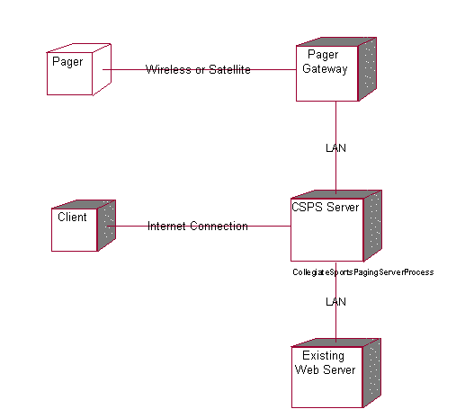
Untitled
Processor CSPS Server
Characteristics
| Scheduling | Preemptive |
| Processes | CollegiateSportsPagingServerProcess |
| Connected Processors | Client | Pager Gateway | Existing Web Server |
Untitled
Processor Pager Gateway
Characteristics
| Scheduling | Preemptive |
| Connected Processors | CSPS Server |
| Connected Devices | Pager |
Untitled
Processor Existing Web Server
Characteristics
| Scheduling | Preemptive |
| Connected Processors | CSPS Server |
Untitled
Processor Client
Characteristics
| Scheduling | Preemptive |
| Connected Processors | CSPS Server |
Untitled
Process CollegiateSportsPagingServerProcess
Priority
Untitled
Association (thePay fee with credit card:Pay fee with credit card) (theSubscriber:Subscriber)
| Derived | No | Link Class | –Not Defined– |
| Element 1 | Pay fee with credit card | Element 2 | Subscriber |
| Role 1 | –Not Named– | Role 2 | –Not Named– |
Untitled
Association (theRead content on website:Read content on website) (theSubscriber:Subscriber)
| Derived | No | Link Class | –Not Defined– |
| Element 1 | Read content on website | Element 2 | Subscriber |
| Role 1 | –Not Named– | Role 2 | –Not Named– |
Untitled
Association (theProvide feedback:Provide feedback) (thePotential Subscriber:Potential Subscriber)
| Derived | No | Link Class | –Not Defined– |
| Element 1 | Provide feedback | Element 2 | Potential Subscriber |
| Role 1 | –Not Named– | Role 2 | –Not Named– |
Untitled
Association (theSubscribe:Subscribe) (thePotential Subscriber:Potential Subscriber)
| Derived | No | Link Class | –Not Defined– |
| Element 1 | Subscribe | Element 2 | Potential Subscriber |
| Role 1 | –Not Named– | Role 2 | –Not Named– |
Untitled
Association (theProvide feedback:Provide feedback) (theAdvertiser:Advertiser)
| Derived | No | Link Class | –Not Defined– |
| Element 1 | Provide feedback | Element 2 | Advertiser |
| Role 1 | –Not Named– | Role 2 | –Not Named– |
Untitled
Association (thePost Advertising Content:Post Advertising Content) (theAdvertiser:Advertiser)
| Derived | No | Link Class | –Not Defined– |
| Element 1 | Post Advertising Content | Element 2 | Advertiser |
| Role 1 | –Not Named– | Role 2 | –Not Named– |
Untitled
Association (thePrint advertiser reports:Print advertiser reports) (theAdvertiser:Advertiser)
| Derived | No | Link Class | –Not Defined– |
| Element 1 | Print advertiser reports | Element 2 | Advertiser |
| Role 1 | –Not Named– | Role 2 | –Not Named– |
Untitled
Association (theCurrent WebNewsOnLine System:Current WebNewsOnLine System) (theSend content:Send content)
| Derived | No | Link Class | –Not Defined– |
| Element 1 | Current WebNewsOnLine System | Element 2 | Send content |
| Role 1 | –Not Named– | Role 2 | –Not Named– |
Untitled
Association (theSend content:Send content) (theCurrent WebNewsOnLine System:Current WebNewsOnLine System)
| Derived | No | Link Class | –Not Defined– |
| Element 1 | Send content | Element 2 | Current WebNewsOnLine System |
| Role 1 | –Not Named– | Role 2 | –Not Named– |
Untitled
Association (theSend page:Send page) (thePager Gateway:Pager Gateway)
| Derived | No | Link Class | –Not Defined– |
| Element 1 | Send page | Element 2 | Pager Gateway |
| Role 1 | –Not Named– | Role 2 | –Not Named– |
Untitled
Association (theApprove story:Approve story) (theEditor:Editor)
| Derived | No | Link Class | –Not Defined– |
| Element 1 | Approve story | Element 2 | Editor |
| Role 1 | –Not Named– | Role 2 | –Not Named– |
Untitled
Association (theEdit profile:Edit profile) (thePotential Subscriber:Potential Subscriber)
| Derived | No | Link Class | –Not Defined– |
| Element 1 | Edit profile | Element 2 | Potential Subscriber |
| Role 1 | –Not Named– | Role 2 | –Not Named– |
Untitled
Association (thePager Gateway:Pager Gateway) (theSend content:Send content)
| Derived | No | Link Class | –Not Defined– |
| Element 1 | Pager Gateway | Element 2 | Send content |
| Role 1 | –Not Named– | Role 2 | –Not Named– |
Untitled
Association (thePaging Service:Paging Service) (theSend page:Send page)
| Derived | No | Link Class | –Not Defined– |
| Element 1 | Paging Service | Element 2 | Send page |
| Role 1 | –Not Named– | Role 2 | –Not Named– |
Untitled
Association (theBaseProfile:BaseProfile) (theUser Profile:User Profile)
| Derived | No | Link Class | –Not Defined– |
| Element 1 | BaseProfile | Element 2 | User Profile |
| Role 1 | –Not Named– | Role 2 | –Not Named– |
Untitled
Association (theSubscriberAccount:SubscriberAccount) (theSubscriberProfile:SubscriberProfile)
| Derived | No | Link Class | –Not Defined– |
| Element 1 | SubscriberAccount | Element 2 | SubscriberProfile |
| Role 1 | –Not Named– | Role 2 | –Not Named– |
Untitled
Association (thePersonalInfo:PersonalInfo) (theSubscriberProfile:SubscriberProfile)
| Derived | No | Link Class | –Not Defined– |
| Element 1 | PersonalInfo | Element 2 | SubscriberProfile |
| Role 1 | –Not Named– | Role 2 | –Not Named– |
Untitled
Association (thePagingPreferences:PagingPreferences) (theSubscriberProfile:SubscriberProfile)
| Derived | No | Link Class | –Not Defined– |
| Element 1 | PagingPreferences | Element 2 | SubscriberProfile |
| Role 1 | –Not Named– | Role 2 | –Not Named– |
Untitled
Association (thePagerInfo:PagerInfo) (theSubscriberProfile:SubscriberProfile)
| Derived | No | Link Class | –Not Defined– |
| Element 1 | PagerInfo | Element 2 | SubscriberProfile |
| Role 1 | –Not Named– | Role 2 | –Not Named– |
Untitled
Association (thePageMeWhenInfo:PageMeWhenInfo) (theSubscriberProfile:SubscriberProfile)
| Derived | No | Link Class | –Not Defined– |
| Element 1 | PageMeWhenInfo | Element 2 | SubscriberProfile |
| Role 1 | –Not Named– | Role 2 | –Not Named– |
Untitled
Association (theContentCatagories:ContentCatagories) (theContent:Content)
| Derived | No | Link Class | –Not Defined– |
| Element 1 | ContentCatagories | Element 2 | Content |
| Role 1 | –Not Named– | Role 2 | –Not Named– |
Untitled
Association (theAdvertiserAccount:AdvertiserAccount) (theAdvertiserProfile:AdvertiserProfile)
| Derived | No | Link Class | –Not Defined– |
| Element 1 | AdvertiserAccount | Element 2 | AdvertiserProfile |
| Role 1 | –Not Named– | Role 2 | –Not Named– |
Untitled
Association (theCompanyInfo:CompanyInfo) (theAdvertiserProfile:AdvertiserProfile)
| Derived | No | Link Class | –Not Defined– |
| Element 1 | CompanyInfo | Element 2 | AdvertiserProfile |
| Role 1 | –Not Named– | Role 2 | –Not Named– |
Untitled
Association (theAdContent:AdContent) (theAdvertiserAccount:AdvertiserAccount)
| Derived | No | Link Class | –Not Defined– |
| Element 1 | AdContent | Element 2 | AdvertiserAccount |
| Role 1 | –Not Named– | Role 2 | –Not Named– |
Untitled
Association (theContentCatagories:ContentCatagories) (theContent:Content)
| Derived | No | Link Class | –Not Defined– |
| Element 1 | ContentCatagories | Element 2 | Content |
| Role 1 | –Not Named– | Role 2 | –Not Named– |
Untitled
Association (theContent:Content) (theContentArchive:ContentArchive)
| Derived | No | Link Class | –Not Defined– |
| Element 1 | Content | Element 2 | ContentArchive |
| Role 1 | –Not Named– | Role 2 | –Not Named– |
Untitled
Association (theAdFrequencyTypes:AdFrequencyTypes) (theAdContent:AdContent)
| Derived | No | Link Class | –Not Defined– |
| Element 1 | AdFrequencyTypes | Element 2 | AdContent |
| Role 1 | –Not Named– | Role 2 | –Not Named– |
Untitled
Association (theContentCatagories:ContentCatagories) (theEditorProfile:EditorProfile)
| Derived | No | Link Class | –Not Defined– |
| Element 1 | ContentCatagories | Element 2 | EditorProfile |
| Role 1 | –Not Named– | Role 2 | –Not Named– |
Untitled
Association (theContentQueue:ContentQueue) (theEditorProfile:EditorProfile)
| Derived | No | Link Class | –Not Defined– |
| Element 1 | ContentQueue | Element 2 | EditorProfile |
| Role 1 | –Not Named– | Role 2 | –Not Named– |
Untitled
Association (theContentQueue:ContentQueue) (theSubscriberProfile:SubscriberProfile)
| Derived | No | Link Class | –Not Defined– |
| Element 1 | ContentQueue | Element 2 | SubscriberProfile |
| Role 1 | –Not Named– | Role 2 | –Not Named– |
Untitled
Message authorizeAndProcessTransaction
| Operation | Not assigned | Message to self | No |
| Sender | –Not Named– | Receiver | –Not Named– |
Untitled
Message authorizeAndProcessTransaction
| Operation | Not assigned | Message to self | No |
| Sender | –Not Named– | Receiver | –Not Named– |
Untitled
Object –Not Named–
| Persistence | Transient | Multiple Instances | No |
Untitled
Object –Not Named–
| Persistence | Transient | Multiple Instances | No |
Untitled
 –Not Named–, role for Element Pay fee with credit card
| Association | –Not Named– | Export Control | PublicAccess |
| Containment | Unspecified | Cardinality | |
| Aggregate | No | Static | No |
| Navigable | Yes |
Untitled
–Not Named–, role for Element Subscriber
| Association | –Not Named– | Export Control | PublicAccess |
| Containment | Unspecified | Cardinality | |
| Aggregate | No | Static | No |
| Navigable | No |
Untitled
–Not Named–, role for Element Read content on website
| Association | –Not Named– | Export Control | PublicAccess |
| Containment | Unspecified | Cardinality | |
| Aggregate | No | Static | No |
| Navigable | Yes |
Untitled
–Not Named–, role for Element Subscriber
| Association | –Not Named– | Export Control | PublicAccess |
| Containment | Unspecified | Cardinality | |
| Aggregate | No | Static | No |
| Navigable | No |
Untitled
–Not Named–, role for Element Provide feedback
| Association | –Not Named– | Export Control | PublicAccess |
| Containment | Unspecified | Cardinality | |
| Aggregate | No | Static | No |
| Navigable | Yes |
Untitled
–Not Named–, role for Element Potential Subscriber
| Association | –Not Named– | Export Control | PublicAccess |
| Containment | Unspecified | Cardinality | |
| Aggregate | No | Static | No |
| Navigable | No |
Untitled
–Not Named–, role for Element Subscribe
| Association | –Not Named– | Export Control | PublicAccess |
| Containment | Unspecified | Cardinality | |
| Aggregate | No | Static | No |
| Navigable | Yes |
Untitled
–Not Named–, role for Element Potential Subscriber
| Association | –Not Named– | Export Control | PublicAccess |
| Containment | Unspecified | Cardinality | |
| Aggregate | No | Static | No |
| Navigable | No |
Untitled
–Not Named–, role for Element Provide feedback
| Association | –Not Named– | Export Control | PublicAccess |
| Containment | Unspecified | Cardinality | |
| Aggregate | No | Static | No |
| Navigable | Yes |
Untitled
–Not Named–, role for Element Advertiser
| Association | –Not Named– | Export Control | PublicAccess |
| Containment | Unspecified | Cardinality | |
| Aggregate | No | Static | No |
| Navigable | No |
Untitled
–Not Named–, role for Element Post Advertising Content
| Association | –Not Named– | Export Control | PublicAccess |
| Containment | Unspecified | Cardinality | |
| Aggregate | No | Static | No |
| Navigable | Yes |
Untitled
–Not Named–, role for Element Advertiser
| Association | –Not Named– | Export Control | PublicAccess |
| Containment | Unspecified | Cardinality | |
| Aggregate | No | Static | No |
| Navigable | No |
Untitled
–Not Named–, role for Element Print advertiser reports
| Association | –Not Named– | Export Control | PublicAccess |
| Containment | Unspecified | Cardinality | |
| Aggregate | No | Static | No |
| Navigable | Yes |
Untitled
–Not Named–, role for Element Advertiser
| Association | –Not Named– | Export Control | PublicAccess |
| Containment | Unspecified | Cardinality | |
| Aggregate | No | Static | No |
| Navigable | No |
Untitled
–Not Named–, role for Element Current WebNewsOnLine System
| Association | –Not Named– | Export Control | PublicAccess |
| Containment | Unspecified | Cardinality | |
| Aggregate | No | Static | No |
| Navigable | Yes |
Untitled
–Not Named–, role for Element Send content
| Association | –Not Named– | Export Control | PublicAccess |
| Containment | Unspecified | Cardinality | |
| Aggregate | No | Static | No |
| Navigable | No |
Untitled
–Not Named–, role for Element Send content
| Association | –Not Named– | Export Control | PublicAccess |
| Containment | Unspecified | Cardinality | |
| Aggregate | No | Static | No |
| Navigable | Yes |
Untitled
–Not Named–, role for Element Current WebNewsOnLine System
| Association | –Not Named– | Export Control | PublicAccess |
| Containment | Unspecified | Cardinality | |
| Aggregate | No | Static | No |
| Navigable | No |
Untitled
–Not Named–, role for Element Send page
| Association | –Not Named– | Export Control | PublicAccess |
| Containment | Unspecified | Cardinality | |
| Aggregate | No | Static | No |
| Navigable | Yes |
Untitled
–Not Named–, role for Element Pager Gateway
| Association | –Not Named– | Export Control | PublicAccess |
| Containment | Unspecified | Cardinality | |
| Aggregate | No | Static | No |
| Navigable | No |
Untitled
–Not Named–, role for Element Approve story
| Association | –Not Named– | Export Control | PublicAccess |
| Containment | Unspecified | Cardinality | |
| Aggregate | No | Static | No |
| Navigable | Yes |
Untitled
–Not Named–, role for Element Editor
| Association | –Not Named– | Export Control | PublicAccess |
| Containment | Unspecified | Cardinality | |
| Aggregate | No | Static | No |
| Navigable | No |
Untitled
–Not Named–, role for Element Edit profile
| Association | –Not Named– | Export Control | PublicAccess |
| Containment | Unspecified | Cardinality | |
| Aggregate | No | Static | No |
| Navigable | Yes |
Untitled
–Not Named–, role for Element Potential Subscriber
| Association | –Not Named– | Export Control | PublicAccess |
| Containment | Unspecified | Cardinality | |
| Aggregate | No | Static | No |
| Navigable | No |
Untitled
–Not Named–, role for Element Pager Gateway
| Association | –Not Named– | Export Control | PublicAccess |
| Containment | Unspecified | Cardinality | |
| Aggregate | No | Static | No |
| Navigable | Yes |
Untitled
–Not Named–, role for Element Send content
| Association | –Not Named– | Export Control | PublicAccess |
| Containment | Unspecified | Cardinality | |
| Aggregate | No | Static | No |
| Navigable | No |
Untitled
–Not Named–, role for Element Paging Service
| Association | –Not Named– | Export Control | PublicAccess |
| Containment | Unspecified | Cardinality | |
| Aggregate | No | Static | No |
| Navigable | Yes |
Untitled
–Not Named–, role for Element Send page
| Association | –Not Named– | Export Control | PublicAccess |
| Containment | Unspecified | Cardinality | |
| Aggregate | No | Static | No |
| Navigable | No |
Untitled
–Not Named–, role for Element BaseProfile
| Association | –Not Named– | Export Control | PublicAccess |
| Containment | Unspecified | Cardinality | 0..1 |
| Aggregate | No | Static | No |
| Navigable | Yes |
Untitled
–Not Named–, role for Element User Profile
| Association | –Not Named– | Export Control | PublicAccess |
| Containment | Unspecified | Cardinality | |
| Aggregate | No | Static | No |
| Navigable | No |
Untitled
–Not Named–, role for Element SubscriberAccount
| Association | –Not Named– | Export Control | PublicAccess |
| Containment | Unspecified | Cardinality | 1 |
| Aggregate | No | Static | No |
| Navigable | Yes |
Untitled
–Not Named–, role for Element SubscriberProfile
| Association | –Not Named– | Export Control | PublicAccess |
| Containment | Unspecified | Cardinality | |
| Aggregate | No | Static | No |
| Navigable | No |
Untitled
–Not Named–, role for Element PersonalInfo
| Association | –Not Named– | Export Control | PublicAccess |
| Containment | Unspecified | Cardinality | 1 |
| Aggregate | No | Static | No |
| Navigable | Yes |
Untitled
–Not Named–, role for Element SubscriberProfile
| Association | –Not Named– | Export Control | PublicAccess |
| Containment | Unspecified | Cardinality | |
| Aggregate | No | Static | No |
| Navigable | No |
Untitled
–Not Named–, role for Element PagingPreferences
| Association | –Not Named– | Export Control | PublicAccess |
| Containment | Unspecified | Cardinality | 1 |
| Aggregate | No | Static | No |
| Navigable | Yes |
Untitled
–Not Named–, role for Element SubscriberProfile
| Association | –Not Named– | Export Control | PublicAccess |
| Containment | Unspecified | Cardinality | |
| Aggregate | No | Static | No |
| Navigable | No |
Untitled
–Not Named–, role for Element PagerInfo
| Association | –Not Named– | Export Control | PublicAccess |
| Containment | Unspecified | Cardinality | 1 |
| Aggregate | No | Static | No |
| Navigable | Yes |
Untitled
–Not Named–, role for Element SubscriberProfile
| Association | –Not Named– | Export Control | PublicAccess |
| Containment | Unspecified | Cardinality | |
| Aggregate | No | Static | No |
| Navigable | No |
Untitled
–Not Named–, role for Element PageMeWhenInfo
| Association | –Not Named– | Export Control | PublicAccess |
| Containment | Unspecified | Cardinality | 1 |
| Aggregate | No | Static | No |
| Navigable | Yes |
Untitled
–Not Named–, role for Element SubscriberProfile
| Association | –Not Named– | Export Control | PublicAccess |
| Containment | Unspecified | Cardinality | |
| Aggregate | No | Static | No |
| Navigable | No |
Untitled
–Not Named–, role for Element ContentCatagories
| Association | –Not Named– | Export Control | PublicAccess |
| Containment | Unspecified | Cardinality | 0..n |
| Aggregate | No | Static | No |
| Navigable | Yes |
Untitled
–Not Named–, role for Element Content
| Association | –Not Named– | Export Control | PublicAccess |
| Containment | Unspecified | Cardinality | |
| Aggregate | No | Static | No |
| Navigable | No |
Untitled
–Not Named–, role for Element AdvertiserAccount
| Association | –Not Named– | Export Control | PublicAccess |
| Containment | Unspecified | Cardinality | 1 |
| Aggregate | No | Static | No |
| Navigable | No |
Untitled
–Not Named–, role for Element AdvertiserProfile
| Association | –Not Named– | Export Control | PublicAccess |
| Containment | Unspecified | Cardinality | 1 |
| Aggregate | No | Static | No |
| Navigable | No |
Untitled
–Not Named–, role for Element CompanyInfo
| Association | –Not Named– | Export Control | PublicAccess |
| Containment | Unspecified | Cardinality | 1 |
| Aggregate | No | Static | No |
| Navigable | No |
Untitled
–Not Named–, role for Element AdvertiserProfile
| Association | –Not Named– | Export Control | PublicAccess |
| Containment | Unspecified | Cardinality | |
| Aggregate | No | Static | No |
| Navigable | No |
Untitled
–Not Named–, role for Element AdContent
| Association | –Not Named– | Export Control | PublicAccess |
| Containment | Unspecified | Cardinality | 0..n |
| Aggregate | No | Static | No |
| Navigable | Yes |
Untitled
–Not Named–, role for Element AdvertiserAccount
| Association | –Not Named– | Export Control | PublicAccess |
| Containment | Unspecified | Cardinality | |
| Aggregate | No | Static | No |
| Navigable | No |
Untitled
–Not Named–, role for Element ContentCatagories
| Association | –Not Named– | Export Control | PublicAccess |
| Containment | Unspecified | Cardinality | |
| Aggregate | No | Static | No |
| Navigable | Yes |
Untitled
–Not Named–, role for Element Content
| Association | –Not Named– | Export Control | PublicAccess |
| Containment | Unspecified | Cardinality | |
| Aggregate | No | Static | No |
| Navigable | No |
Untitled
–Not Named–, role for Element Content
| Association | –Not Named– | Export Control | PublicAccess |
| Containment | Unspecified | Cardinality | |
| Aggregate | No | Static | No |
| Navigable | Yes |
Untitled
–Not Named–, role for Element ContentArchive
| Association | –Not Named– | Export Control | PublicAccess |
| Containment | Unspecified | Cardinality | |
| Aggregate | No | Static | No |
| Navigable | No |
Untitled
–Not Named–, role for Element AdFrequencyTypes
| Association | –Not Named– | Export Control | PublicAccess |
| Containment | Unspecified | Cardinality | |
| Aggregate | No | Static | No |
| Navigable | Yes |
Untitled
–Not Named–, role for Element AdContent
| Association | –Not Named– | Export Control | PublicAccess |
| Containment | Unspecified | Cardinality | |
| Aggregate | No | Static | No |
| Navigable | No |
Untitled
–Not Named–, role for Element ContentCatagories
| Association | –Not Named– | Export Control | PublicAccess |
| Containment | Unspecified | Cardinality | |
| Aggregate | No | Static | No |
| Navigable | Yes |
Untitled
–Not Named–, role for Element EditorProfile
| Association | –Not Named– | Export Control | PublicAccess |
| Containment | Unspecified | Cardinality | |
| Aggregate | No | Static | No |
| Navigable | No |
Untitled
–Not Named–, role for Element ContentQueue
| Association | –Not Named– | Export Control | PublicAccess |
| Containment | Unspecified | Cardinality | 1 |
| Aggregate | No | Static | No |
| Navigable | Yes |
Untitled
–Not Named–, role for Element SubscriberProfile
| Association | –Not Named– | Export Control | PublicAccess |
| Containment | Unspecified | Cardinality | |
| Aggregate | No | Static | No |
| Navigable | No |
Untitled
Module Diagram: Component View / Main

Untitled
Package Component View
| Parent Package | None |
Property Settings
C++
| Directory | AUTO GENERATE | DirectoryIsOnSearchList | False |
| PrecompiledHeader |
Untitled
Package Use Case View
| Parent Package | None | Assigned Component Package | –Not Defined– |
| Global | Yes |
| Packages | Use-Case Model |
Property Settings
C++
| IsNamespace | False | Indent | 2 |
| CodeName | GenerateEmptyRegions | All | |
| GenerateEmptyRegionSet | None, Preserved, Unpreserved, All |
Untitled
Use Case Diagram: Use Case View / Main
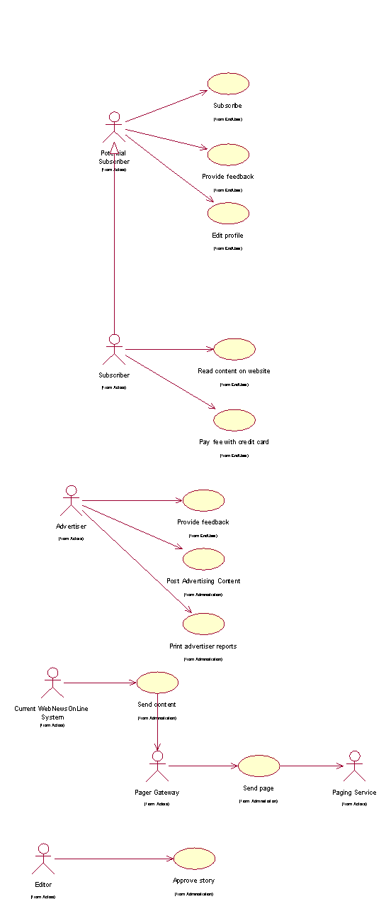
Untitled
Package Logical View
| Parent Package | None | Assigned Component Package | Component View |
| Global | Yes |
| Packages | Process View | Use Case Realizations | Design Model |
Property Settings
C++
| IsNamespace | False | Indent | 2 |
| CodeName | GenerateEmptyRegions | All | |
| GenerateEmptyRegionSet | None, Preserved, Unpreserved, All |
Untitled
Class Diagram: Logical View / Main
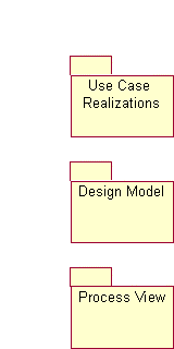
Course Registration System
Vision
Version 1.0
Revision History
| Table | Version | Description | Author |
|---|---|---|---|
| 1/Dec/98 | Draft | Initial Draft | Sue Gamble |
| 13/Dec/98 | 1.0 | Minor revisions following Peer Review. Added performance requirements. | Sue Gamble |
| | | |
| | | |
Table of Contents
1.3 Definitions, Acronyms and Abbreviations
2.3 Product Position Statement
3 Stakeholder and User Descriptions
3.7 Key Stakeholder / User Needs
3.8 Alternatives and Competition
4.3 Assumptions and Dependencies
4.5 Licensing and Installation
5.5 Enter, Update, and View Professor Information
5.8 Enter, Update, and View Student Information
5.10 View Course Catalog Information
9.4 Environmental Requirements
10.3 Installation Guides, Configuration, Read Me File
Vision
1 Introduction
1.1 Purpose
The purpose of this document is to define the high-level requirements of the Wylie course registration (C-Registration) system in terms of the needs of the end users.
1.2 Scope
This Vision Document applies to the Wylie course registration system, which will be developed by the Wylie College Information Systems (IT) department. The IT department will develop this client-server system to interface with the existing course catalog database.
The C-Registration System will enable students to register for courses on-line. The C-Registration System allows professors to select their teaching courses and to maintain student grades.
1.3 Definitions, Acronyms and Abbreviations
See the Glossary [5].
1.4 References
Applicable references are:
Course Registration System System Business Case, WyIT388, DRAFT, 1998, Wylie College IT.
Course Billing Interface Specification, WC93332, 1985, Wylie College Press.
Course Catalog Database Specification, WC93422, 1985, Wylie College Press.
Course Registration System Stakeholder Requests Document, WyIT389, V1.0, 1998, Wylie College IT.
Course Registration System Glossary, WyIT406, V1.0, 1998, Wylie College IT.
6. Course Registration System Requirements Attributes Guidelines, WyIT404, V1.0, 1998, Wylie College IT.
2 Positioning
2.1 Business Opportunity
This project will be replacing the entire front-end of the existing course registration system with a state-of-the-art on-line system that allows student and professor access through PC clients.
The current registration system has been in use since 1985 and lacks the capacity to handle the student and course load projected for year 2000. In addition, the current system is outdated mainframe technology, which only supports access through the clerk in the Registration Office. The new system will enable all professors and students to access the system through PCs connected to the Wylie College computer network and through any personal computer connected through the Internet.
The new system will bring Wylie College to the leading edge in course registration systems thus improving the image of the College, attracting more students, and streamlining administrative functions.
2.2 Problem Statement
| The problem of | The outdated and largely manual student registration process at Wylie College |
| affects | Students, professors, and College administration. |
| The impact of which is | A slow and costly process combined with dissatisfied students and professors. |
| A successful solution would | Improve the image of the College, attract more students, and streamline administrative registration functions. |
2.3 Product Position Statement
| For | Wylie College students, professors, and the course registrar |
| Who | Attend, teach, or administer college courses |
| The Course Registration System | Is a tool |
| That | Enables online course registration and access to course and grade information |
| Unlike | The existing outdated mainframe registration system |
| Our product | Provides up-to-date information on all courses, registrations, teachers, and grades to all users from any PC connected via the College LAN or internet. |
3 Stakeholder and User Descriptions
This section describes the users of the Wylie Course Registration System. There are 3 types of users of the C-Registration System; the Course Registrar, the Students, and the Professors.
3.1 Market Demographics
The University User Community is a large sophisticated community that demands the flexibility and response time that an on-line course registration can provide.
The users are educated, computer literate, and in most cases own personal computers in their homes. The ability to register for courses via personal computers and to review their grades on-line would greatly streamline course registration.
The Course Register works out of the College Admin Headquarters building and is connected to the campus LAN. The students and professors have free access to the LAN through personal computers situated in the campus library and student lounge building.
The initial release of C-Registration will be limited to Wylie College. Marketing subsequent releases to schools, colleges, and universities is under consideration by the Wylie IT Department. As a result, Course Registration will be designed to be expandable and all user community data (i.e. College Name) will be table driven and easily modifiable upon system installation.
3.2 Stakeholder Summary
| Name | Represents | Role |
|---|---|---|
| IT Executive | IT Department and Wylie College as whole. | Responsible for project funding approval. Monitors project progress. |
| Registrar | The office of the registrar, administrative and data entry personnel. | Ensures that the system will meet the needs of the registrar, who has to manage the course registration data, including professor and student databases. |
| Student | Students | Ensures that the system will meet the needs of students. |
| Professor | Professors | Represents the interests of the faculty (professors). |
3.3 User Summary
| Name | Description | Stakeholder |
|---|---|---|
| Registrar | Manages the database of professors and students, opens and closes courses to registration. | self-represented |
| Student | Registers for courses, queries for grades and other course information. | self-represented |
| Professor | Selects courses to teach. Enters student grades. | self-represented |
3.4 User Environment
The University User Community is a large sophisticated community that demands the flexibility and response time that an on-line course registration can provide.
The users are educated, computer literate, and in most cases own personal computers in their homes. The ability to register for courses via personal computers and to review their grades on-line would greatly streamline course registration.
The initial release of C-Registration will be limited to Wylie College. Marketing subsequent releases to schools, colleges, and universities is under consideration by the Wylie IT Department. As a result, Course Registration will be designed to be expandable and all user community data (i.e. College Name) will be table driven and easily modifiable upon system installation.
3.5 Stakeholder Profiles
3.5.1 IT Executive
| Representative | John Whitewood, IT Department Head |
| Description | Approval Authority |
| Type | Understands the college’s financial status, and the long term vision of the Board Of Governors. |
| Responsibilities | Represents the IT Department and the Board Of Governors. Monitor’s project status, and has authority over budget approval. Ensures that the project meets short term and long term goals of the college. Plans for potential re-sale opportunities, and long term maintenance of the system. |
| Success Criteria | Success is completion of the project within approved budget, and a demonstrated reduction in registrar workload (and therefore reduced cost for the projected future). There must also be a general perception by the Board of Governors that the project meets user needs. The system should be easily modified for use by other colleges, for potential re-sale opportunities. The stakeholder is rewarded by receiving recognition by the Board of Governors. |
| Involvement | Management reviewer. Budgetary approval signatory. Involved in staff performance reviews. |
| Deliverables | None. |
| Comments / Issues | None. |
3.5.2 Registrar
| Representative | Karen Hansen |
| Description | User |
| Type | The Registrar is typically a college-educated professional with full computer skills. The Registrar is trained and experienced with the use of the current batch-oriented registration . |
| Responsibilities | The Registrar is responsible for administering course registration for each school term. This includes supervising administrative and data entry personnel. |
| Success Criteria | The registrar’s primary responsibility will be maintaining student and professor databases, and opening/closing courses to registration. The registrar’s office will also be required to perform data entry for students and professors without online access to the system. A successful system is one which substantially reduces the workload on administrative/data entry staff. The primary tasks performed by the registrar must be easy to learn, and quick to perform. Also, the system must have good availability, and reliability, and security. The stakeholder is rewarded by reduction in onerous data entry workload, simplification of existing tasks, and quick convenient access to required information. |
| Involvement | Management reviewer - especially related to functionality and useability of features required by the Registrar staff. |
| Deliverables | None |
| Comments / Issues | None. |
3.5.3 Student
| Representative | Jane Austen |
| Description | User |
| Type | Student Representative to the Board of Governors. |
| Responsibilities | Ensure that the system will be acceptable to students, both in terms of ease of use and also performance/reliability. Up to 2000 students will use the C-Registration System each school term to register for courses and to review their final grades. The students are typically educated, computer literate, and have access to the Internet. It is expected that each term 10% of the students will be registering at Wylie for the first time and will be unfamiliar with the course registration process. |
| Success Criteria | Success is when students using the system for the first time, under normal to heavy usage levels, report that the system is easy to use and worked well. The stakeholder is rewarded by receiving recognition by the Board of Governors for his/her involvement, and by being re-elected for another term. |
| Involvement | Management reviewer - especially features affecting students and usability concerns. |
| Deliverables | None. |
| Comments / Issues | None. |
3.5.4 Professor
| Representative | Dr. Susan Smythe |
| Description | User |
| Type | Faculty representative. |
| Responsibilities | Ensures that the system will be acceptable to professors, both those with and without computer access. The Professors that will use C-Registration are educated, computer literate and familiar with the Wylie registration process. It can be assumed that not all Professors have personal computers in their home and that not all Professors have Internet access. |
| Success Criteria | Success is when most, if not all, professors are able and willing to use the system to select courses, and enter grades, and when professors report that students are no longer calling to ask about final grades. Success is also when professors are able to query for most course registration data online. The stakeholder is rewarded by receiving peer recognition from other faculty. |
| Involvement | Management reviewer - especially usability of features affecting professorial functions, such as course selection and grade entry. |
| Deliverables | None. |
| Comments / Issues | None. |
3.6 User Profiles
Covered under the previous section.
3.7 Key Stakeholder / User Needs
A representative sampling of students, professors, as well as the current Course Registrar completed a User Survey to determine the user problems with the existing course registration system and to solicit user input on improvements. The complete survey results are included in the Stakeholder Requests Document [4]. A summary of the survey results are listed below in order of relative importance from high to low:
| Need | Priority | Concerns | Current Solution | Proposed Solutions |
|---|---|---|---|---|
| Student Course Registration | High | Student Course Registration is slow and inefficient. | Currently students must complete a course registration form and submit it to the Registrar. The Registrar takes up to 2 weeks to process the form and another week to send the confirmation back to the student. At this point, any schedule changes due to full courses or student preference require the entire three week process to be repeated. This provides students limited flexibility in selecting their schedule of courses. | Students would like to have online access to quickly determine course availability and assigned professors. |
| Early access to Student Grades | Medium | Long delay to get grades, continuous queries to professors. | The final report cards are typically mailed out to the students 8 weeks after the start of the examination period. During this time, students continually phone their professors in attempts to find out their marks sooner | Online access to individual course grades was a recommendation from most students completing the survey. |
| Low clerical costs | Medium | Clerical effort is time intensive and costly. | The Registrar and 2-3 temporary clerical hires take 400 - 500 hours each term to process the course registration paperwork. Much of this time is spent entering information into the main course registration database and then re-registering students into other courses to resolve schedule conflicts and course availability problems. | Student access to the course registration system would effectively reduce this effort to zero. |
3.8 Alternatives and Competition
The user community was unaware of any viable alternatives or off-the-shelf solutions. The user community supported the strategy that the system should be developed internally by the College in order to reduce costs, ensure appropriate functionality, and to guarantee continued support and maintenance on the system.
4 Product Overview
This section provides a high level view of the C-Registration System capabilities, interfaces to the external Billing System and Course Catalog Data Base System, and the system configuration.
4.1 Product Perspective
The C-Registration System will replace the existing mainframe course registration system at Wylie College. The new system will interface with the existing Billing System and Course Catalog Database System as shown in the context diagram below (see Figure 6.1.1).
The C-Registration System will consist of a client component and server component as illustrated in Figure 6.1.2. The server component resides on the Wylie College UNIX Server. The server component must interface with the Billing and Course Catalog Database Systems on the College DEC VAX Main Frame. This interface is supported by an existing Open SQL Interface.
The client component resides on a personal computer. The College PCs will be setup with the client component installed. Any non-college PCs must download the client software from the UNIX Server via the Internet. Once the client component is installed on the PC, the user may access the C-Registration System from the PC through the College LAN or Internet. A valid ID number and password must be entered in order for access to be granted.

Figure 6.1.1 C-Registration System Context Diagram

Figure 6.1.2 C-Registration System Overview
4.2 Summary of Capabilities
The table in this section identifies the main capabilities of the C-Registration System in terms of benefits and features. The features are further described in section 7 of this document. Refer to the Glossary [5] for a description of terms.
| Customer Benefit | Supporting Features |
|---|---|
| Up-to-date course information | The system accesses the Course Catalog Database for up-to-date information on all courses offered at Wylie College. For each course, the Students and Professors may review the course description, prerequisites, assigned teachers, class locations, and class times. |
| Up-to-date registration information | All course registrations are immediately logged in the Registration Database to provide up-to-date information on full or cancelled courses. |
| Easy and timely access to course grades | Students can view their grades in any course simply by providing their user ID and password. Students may access the registration system from any College PC or from their home PC via the internet. Professors enter all student marks directly into the Registration Database from their PCs. |
| Access from any College PC | Students may access the registration system from any College PC or from their home PC via the internet. Installation of the client component of the C-Registration System on a PC is an easy to follow process using the internet. |
| Easy and convenient access from your PC at home | Students may access the registration system from any College PC or from their home PC via the internet. |
| Secure and confidential | A valid user ID and password is required to gain access to the C-Registration System. Student report card information is protected from unauthorized access. |
| Instant feedback on full or cancelled courses | All course registrations are immediately logged in the Registration Database to provide up-to-date information on full or cancelled courses. |
4.3 Assumptions and Dependencies
The following assumptions and dependencies relate to the capabilities of the C-Registration System as outlined in this Vision Document:
o The existing Billing and Course Catalog Database Systems which reside on the College DEC VAX Mainframe will continue to be supported until at least 2005.
o The external interfaces of the Billing and Course Catalog Database Systems are as defined in [2] and [3] and will not be altered.
o It is assumed that the College will continue to operate and support the existing UNIX Server and the DEC VAX Mainframe until at least 2005.
o It is assumed that additional funding will be available by 2005 to replace the legacy Billing and Course Catalog Database Systems.
o Implementation of the new registration system in time for the January 2000 school term is dependent upon funding approval by March 1st, 1999.
4.4 Cost and Pricing
Due to funding constraints, the costs for developing the system must not exceed $1,200,000.
It is anticipated that existing computers of the college will be used as the target machines and that no hardware budget is required.
4.5 Licensing and Installation
There are no licensing requirements for V1.0 of the system, as it will be available only to Wylie College.
Installation of the client component must be available via diskette, CD, or downloadable from the Internet.
Installation of the server component must provide the options for retaining the existing Registration Database (without loss of any data) or generating a new Database.
5 Product Features
This section defines and describes the features of the C-Registration System. Features are the high-level capabilities of the system that are necessary to deliver benefits to the users.
5.1 Logon
Students, professors, and the Course Registrar shall provide a valid ID and password for entry to the C-Registration System. Users are assigned their ID and a temporary password at the time they apply for admission to the College. The system shall enable a user to change their temporary password.
5.2 Register for Courses
The system shall display available courses to the student upon request. The student shall be able to query based upon course name, course code, and department. The system shall accept course registrations from students and shall validate based upon course availability, schedule conflicts, and completed pre-requisite courses. The system shall notify the student immediately if the course registration does not succeed.
The system shall allow the student to change course selections prior to the end of the registration period.
5.3 Course Cancellations
The system shall allow the Registrar to cancel courses. The Registrar typically reviews all courses at the end of the registration period and cancels courses that have no assigned Professor or which have less than 3 registered students. The Course Registrar notifies students of cancelled courses by telephone or mail.
5.4 Student Billings
The system shall send notifications to the Billing System following closure of the Registration period. These notifications shall include student name, address, course selections, and payment due.
5.5 Enter, Update, and View Professor Information
The system shall accept and update professor information, including name, address, phone, fax, and email address. Professor information shall be available to the Professors and Course Registrar for viewing.
5.6 View Student Grades
The system shall enable a student to view one course grade or their entire report card. The system shall protect the student grade information from access from any user other than the student and the Professors.
5.7 Select Courses to Teach
The system shall enable Professors to sign up for courses to teach prior to the end of the Registration period.
5.8 Enter, Update, and View Student Information
The system shall accept and update student information, including student ID, name, address, phone number, and email address. Student information shall be available to the Professors and Course Registrar for viewing. The system shall ensure that a student only has access to his or her own student information. The Registrar maintains student information.
5.9 Record Student Grades
The system shall accept, validate, and retain student grades entered by the Professor.
5.10 View Course Catalog Information
The course catalog information maintained in the Course Catalog Database shall be displayed to the user upon request. Users shall be able to query for information based upon course name, course code, professor name, and department.
5.11 View Course Schedule
The system shall display the complete course schedule for a specific student upon request by that student.
5.12 Monitor for Course Full
The system shall ensure that no course is filled beyond the limit of 10 students.
6 Constraints
In addition to the assumptions and dependencies listed in Section 6, the following constraints apply to the C-Registration System:
- The system shall not require any hardware development or procurement.
- The course information available is limited to the type of data supported by the existing Course Catalog Database.
7 Quality Ranges
This section defines the quality ranges for performance, robustness, fault tolerance, usability, and similar characteristics for the C-Registration System
Availability: The System shall be available 24 hours a day, 7 days a week.
Usability: The System shall be easy-to-use and shall be appropriate for the target market of computer-literate students and professors.
Usability: The System shall include online help for the user. Student and Professor users should not require the use of a hardcopy Manual to use the System.
Maintainability: The System shall be designed for ease of maintenance. All college-specific data should be table-driven and modifiable without recompilation of the System.
8 Precedence and Priority
This section provides some direction on the relative importance of the proposed system features. The features defined in this Vision Document should be included in the first 2 releases of the system. All features critical to student registration are planned for the first release.
As development progresses on this system, the feature attributes (referenced in Section 7 of this document) will be used to weight the relative importance of the features and to plan the release content. The benefit, effort, and risk attributes are used to determine priority of a feature and target release.
It is anticipated that the C-Registration System will be released for general use at Wylie College through 2-4 main releases.
Release 1 must contain as a minimum the basic functionality as listed below:
- Logon
- Register for Courses
- Interface to Course Catalog Database
- Maintain Student Information
- Maintain Professor Information
Release 2 should include:
- Submit Student Grades
- View Grades
- Select Courses to Teach
The functionality for Release 3 has not yet been determined. It is anticipated that this release will contain enhancements to the existing functionality.
Future replacement of the legacy Billing System and Course Database System is targeted for Release 4 in Year 2005.
9 Other Product Requirements
9.1 Applicable Standards
The desktop user-interface shall be Windows 95/98 compliant.
9.2 System Requirements
The system shall interface with the existing Course Catalog Database System. C-Registration shall support the data format as defined in [3].
The system shall interface with the existing Billing System and shall support the interface as defined in [2].
The server component of the system shall operate on the College Campus Server and shall run under the UNIX operating system.
The client component of the system shall operate on any personal computer with a 486 Microprocessor or better.
The client component of the system shall not require more than 32 MB RAM and 20 MB Disk Space.
The client component of the system shall run on Windows 95, Windows 98, and Microsoft Windows NT.
9.3 Performance Requirements
The system shall support up to 2000 simultaneous users against the central database at any given time, and up to 500 simultaneous users against the local servers at any one time.
The system shall provide access to the legacy Course Catalog Database with no more than a 10 second latency.
The system shall complete 80% of all transactions within 2 minutes.
9.4 Environmental Requirements
None.
10 Documentation Requirements
This section describes the documentation requirements of the C-Registration System.
10.1 User Manual
The User Manual shall describe use of the System from the students’, professors’, and Registrar’s view point. The User Manual shall include:
- Minimum System Requirements
- Installation of the PC client
- Logging On
- Logging Off
- All System Features
- Customer Support Information
The User Manual shall follow the format as defined in the Wylie College User Manual template.
The User Manual should range from 50 - 100 pages. The User Manual page dimensions shall be 7 by 9 inches. The User Manual shall be available as hardcopy and through the online help.
10.2 On-line Help
Online Help shall be available to the user for each system function. Each topic covered in the User Manual shall also be available through the online help.
10.3 Installation Guides, Configuration, Read Me File
The Installation Guide for the server portion shall include:
- Minimum System Requirements
- Installation Instructions
- Configuring College-Specific Parameters
- How to Initialize the C-Registration Database
- How to Retain the Existing C-Registration Database
- Customer Support Information
- How to Order Upgrades
The Read Me File shall be available for display following installation. The Read Me File will also reside on disk and be available for viewing at any time by the user. The Read Me File shall include:
New release features
Known bugs and workarounds.
10.4 Labeling and Packaging
The Wylie College logo shall be prominent on the user documentation and splash screens.
As the initial releases are strictly for Wylie College and not the general market, product marketing literature, product packaging, and promotional materials will not be developed.
<project> Use-Case: <use-case name>
Brief Description
<brief description of use-case>
Actor Brief Descriptions
Preconditions
<pre-condition 1>
Basic Flow of Events
1. <basic flow steps>
2. ..
3. The use case ends.
Alternative Flows
<alternate flow 1>
Subflows
<subflow 1>
Key Scenarios
<scenario 1>
Post-conditions
<post-condition 1>
Extension Points
<extension point 1>
Special Requirements
<supplementary requirement 1>
Additional Information
Revision History
| Date | Version | Description | Author |
| <dd/mmm/yy> | <x.x> | <details> | <name> |
Table of Contents
[1. Introduction](#1. Introduction)
[1.1 Purpose](#1.1 Purpose)
[1.2 Scope](#1.2 Scope)
[1.3 Definitions, Acronyms, and Abbreviations](#1.3 Definitions, Acronyms and Abbreviations)
[1.4 References](#1.4 References)
[1.5 Overview](#1.5 Overview)
[2. Version Description](#2. Version Description)
[2.1 Inventory of Materials](#2.1 Inventory of Materials)
[2.1.1 Handling Considerations](#2.1.1 Handling Considerations)
[2.2 Inventory of Software Contents](#2.2 Inventory of Software Contents)
[2.3 Changes](#2.3 Changes)
[2.4 Adaptation Data](#2.4 Adaptation Data)
[2.5 Installation Instructions](#2.5 Installation Instructions)
[2.6 Known Errors and Problematic Features](#2.6 Known Errors and Problematic Features)
Bill of Materials
1. Introduction
[Provide an overview of the entire document.]
1.1 Purpose
[Describe the purpose of the software to which this document applies**.**]
1.2 Scope
[Identify the recipients for the items identified in the Bill of Materials; for example, the source code is typically not released to all recipients.]
1.3 Definitions, Acronyms, and Abbreviations
[This subsection provides the definitions of all terms, acronyms, and abbreviations required to properly interpret the Bill of Materials. This information may be provided by reference to the project’s Glossary.]
1.4 References
[This subsection provides a complete list of all documents referenced elsewhere in the Bill of Materials. Identify each document by title, report number if applicable, date, and publishing organization. Specify the sources from which the references can be obtained. This information may be provided by reference to an appendix or to another document.]
1.5 Overview
[This subsection describes what the rest of the Bill of Materials contains and explains how the document is organized.]
2. Version Description
2.1 Inventory of Materials
[List all the physical media, such as CDs, floppies, and so on, and associated documentation that make up the software version being released. Identify numbers, titles, abbreviations, dates, versions and release numbers as applicable.]
2.1.1 Handling Considerations
[Describe safeguards for handling the material, such as concerns for static and magnetic fields, and instructions and restrictions regarding duplication and licensing.]
2.2 Inventory of Software Contents
[List all files that make up the software version being released. Identify numbers, titles, abbreviations, dates, versions, and release numbers as applicable.]
2.3 Changes
[List all changes incorporated into the software version since the previous version. Identify, as applicable, the problem reports and Change Requests associated with each change. Describe the effect of each change on software use or operation, as applicable.]
2.4 Adaptation Data
[Identify any site-unique data contained in the software.]
2.5 Installation Instructions
[Provide or reference the following information:
instructions for installing the software
procedures for determining whether the version has been properly installed]
2.6 Known Errors and Problematic Features
[Identify any possible problems or known errors with the software at the time of release. Describe steps that can be taken to recognize, avoid, correct or handle any problematic features.]
Business Architecture Document
[7. Human Resource View](#7. Human Resource View)
[7.1 Remuneration and Incentives](#7.1 Remuneration and Incentives) [7.2 Cultural Aspects](#7.2 Cultural Aspects) [7.3 Competencies](#7.3 Competencies)
[8. Domain View](#8. Domain View)
[9. Geographic View](#9. Geographic View)
[10. Communication View](#10. Communication View)
[11. Architectural Trade-offs](#11. Architectural Trade-offs)
Business Architecture Document
1. Introduction
[The introduction of the Business Architecture Document provides an overview of the entire Business Architecture Document. It needs to include the purpose, scope, definitions, acronyms, abbreviations, references and overview of the Business Architecture Document.]
1.1 Purpose
This document provides a comprehensive architectural overview of the business, using a number of different architectural views to depict different aspects of the business. It is intended to capture and convey the significant architectural decisions which have been made on the business.
[This section defines the purpose of the Business Architecture Document, in the overall project documentation, and briefly describes the structure of the document. The specific audiences for the document should be identified, with an indication of how they are expected to use the document.]
1.2 Scope
[A brief description of what the Business Architecture Document applies to; what is affected or influenced by this document.]
1.3 Definitions, Acronyms, and Abbreviations
[This subsection provides the definitions of all terms, acronyms, and abbreviations required to properly interpret the Business Architecture Document. This information may be provided by reference to the project’s Business Glossary. Include the operational definitions of business architecture, and application architecture and technical architecture if applicable.]
1.4 References
[This subsection provides a complete list of all documents referenced elsewhere in the Business Architecture Document. Identify each document by title, report number if applicable, date, and publishing organization. Specify the sources from which the references can be obtained. This information may be provided by reference to an appendix or to another document.]
1.5 Overview
[This subsection describes what the rest of the Business Architecture Document contains and explains how the Business Architecture Document is organized.]
2. Architectural Representation
[This section describes what business architecture is for the current business, and how it is represented. Describe the views that will be used to represent the architecture and indicate which stakeholders each view is applicable to. Also describe what types of model elements each view contains.]
3. Architectural Drivers
[This section describes the forces within the business and its environment that shape the business architecture. These are very important for bounding architectural decisions and understanding the consequences of those decisions. Architectural drivers can be classified into architectural goals, which define a desire, and architectural constraints, which imply mandatory compliance to a particular condition.]
4. Market View
[This view defines the markets the business operates in, the current or expected trends and changes in these markets (such as growth or competition), targeted customer profiles and the products and/or services the business offers to its customers (value proposition).]
5. Business Process View
[This section lists business use cases or business scenarios from the business use-case model if they represent some significant, central capability of the final business, or if they have a large architectural coverage they exercise many architectural elements or if they stress or illustrate a specific, delicate point of the business architecture. This view is mandatory.]
5.1 Business Context
[This section shows the business in the context of its environment, including partners and suppliers. Use a business context diagram - showing the business actors and the layers in the business architecture they interact with.]
5.2 Architecturally Significant Business Use Cases
[This section shows the architecturally significant business use cases. Include a diagram showing these business use cases in relation to the business actors and provide the description and flow of events of each of the business use cases. Architecturally significant business use cases are those business use cases that provide broad functional coverage and/or exercise a critical part of the business. Core business use cases typically provide broad coverage.]
6. Organization View
[This view describes the structure of the organization and the manner in which business processes are performed. The architecturally significant parts of the organization are described. This view is mandatory.]
6.1 Organization Structure
[This section provide an overview of the high-level structure of the organization into business systems and the roles and responsibilities of and within these units.]
6.2 Business Use-Case Realizations
[This section illustrates how the organization performs the architecturally significant business use cases by showing how business systems and business workers and entities interact. These business use case realizations provide a mapping between the business use cases and the organization structure.]
6.3 General Patterns of Behavior
[This section describes general patterns of interaction within the business. These can be used to describe generic or reusable processes (or sub-processes) that are performed in many different parts of the organization or under different circumstances. These patterns can be used to show, for example, how a request for a generic resource is submitted and processed.]
7. Human Resource View
[This view describes the architecturally significant human resource aspects of the business. Remuneration and incentives, corporate culture and competencies are described. This view is optional.]
7.1 Remuneration and Incentives
[This section identifies the major remuneration bracket (salary scales) and describes the incentive mechanisms for rewarding above average performance. This aspect of the human resource view is useful for re-aligning the remuneration and incentives policy in order to stimulate organizational change.]
7.2 Cultural Aspects
[This section describes the major cultural characteristics of the organization and the mechanisms for encouraging and enforcing these cultural characteristics. For example, in an organization where teamwork and initiative are considered important aspects of the culture, an annual inter-team volleyball competition and a monthly prize for the best initiative would be mechanisms that enforce these cultural aspects.]
7.3 Competencies
[This section describes the competency profiles within the organization, in terms of skills, experience, attitude and motivation. These profiles can be used to ensure that the skills required by the organization are developed and available in the long term. Education and training mechanisms for ensuring that the required competencies are acquired by and developed within the organization can also be described. Examples include recruitment strategies and special interest groups, respectively.]
8. Domain View
[This section describes the major concepts and information structures to be found within the business and its environment. This view is mandatory. These concepts and information structures (business entities) and their relationships should be shown in class diagrams. Ensure that each business entity has a description. For example, an insurance firm may have business entities such as Customer, PolicyOwner, Beneficiary, Account, Contract, Policy, Claim and InsuredObject.]]
9. Geographic View
[This view describes the geographic distribution of the organization structure and functions. This view is optional. Provide a diagram showing the physical locations at which the business has some sort of presence. These locations can be addresses within the same city, different cities or different countries. Ships can also be counted as physical locations.]
10. Communication View
[This view provides a topological overview of communication within the business. Use class diagram to indicate communicating parties, which could be communicating business processes, organization units, business workers, business actors, physical locations (localities). Associations between these parties indicate the existence of a communication link. The properties of each link can be described. Consider the subject, medium (verbal, email, video-conferencing), frequency, effectiveness, cost, direction (unidirectional or bi-directional), value and risk (impact of being tapped/misused).]
11. Architectural Trade-offs
[This section describes the how the business architecture realizes the architectural goals and constraints described above. For each architectural driver and constraint listed above, discuss how the business architecture supports that driver or constraint. Pay special attention to conflicts, because the architecture is an optimal solution to many conflicting forces.]
Business Case
1. Introduction
[The introduction of the Business Case should provide an overview of the entire document. It should include the purpose, scope, definitions, acronyms, abbreviations, references, and overview of this Business Case.]
2. Product Description
[To give a context to the reader, briefly describe the product that is to be developed. Include the name of the system and possibly an acronym, if one is used. Explain what problem it solves and why the development will be worth the effort. Refer to the Vision document.]
*3.*Business Context
[Define the business context for the product. In which domain is it going to function (for example, telecom or bank) and what market who are the users? State whether the product is being developed to fulfill a contract or if it is a commercial product. If it is a continuation of an existing project, this should also be mentioned.]
4. Product Objectives
[State the objectives for developing the product the reasons why this is worthwhile. This includes a tentative schedule, and some assessment of schedule risks. Clearly defined and expressed objectives provide good grounds for formulating milestones and managing risks; that is, keeping the project on track and ensuring its success.]
5. Financial Forecast
[An example of a possible cost-benefit analysis table is shown below.]
| Financial Forecast - <n> years | Value | Totals |
| Benefits | ||
| [revenue enhancement] | $ | |
| [expense reduction] | $ | |
| [intangibles (good will, visibility)] | $ | $ |
| Costs | ||
| [capital] | $ | |
| [expense] | $ | $ |
| ROI (benefits/costs) | % |
6. Constraints
[Express the constraints under which the project is undertaken. These constraints impact risk and cost. They could be things like external interfaces that the system must adhere to, standards, certifications or a technical approach employed for strategic reasons, such as using a certain database technology or distribution mechanisms.]
Revision History
| Date | Version | Description | Author |
| <dd/mmm/yy> | <x.x> | <details> | <name> |
Table of Contents
[1. Introduction](#1. Introduction)
[1.1 Purpose](#1.1 Purpose)
[1.2 Scope](#1.2 Scope)
[1.3 Definitions, Acronyms and Abbreviations](#1.3 Definitions, Acronyms and Abbreviations)
[1.4 References](#1.4 References)
[1.5 Overview](#1.5 Overview)
[2. Product Description](#2. Product Description)
[3. Business Context](#3. Business Context)
[4. Product Objectives](#4. Product Objectives)
[5. Financial Forecast](#5. Financial Forecast)
[6. Constraints](#6. Constraints)
Business Case
1. Introduction
[The introduction of the Business Case should provide an overview of the entire document. It should include the purpose, scope, definitions, acronyms, abbreviations, references, and overview of this Business Case.]
1.1 Purpose
[Specify the purpose of this Business Case.]
1.2 Scope
[A brief description of the scope of this Business Case; what Project(s) it is associated with, and anything else that is affected or influenced by this document.]
1.3 Definitions, Acronyms and Abbreviations
[This subsection should provide the definitions of all terms, acronyms, and abbreviations required to properly interpret the Business Case. This information may be provided by reference to the project Glossary.]
1.4 References
[This subsection should provide a complete list of all documents referenced elsewhere in the Business Case. Each document should be identified by title, report number (if applicable), date, and publishing organization. Specify the sources from which the references can be obtained. This information may be provided by reference to an appendix or to another document.]
1.5 Overview
[This subsection should describe what the rest of the Business Case contains and explain how the document is organized.]
2. Product Description
[To give a context to the reader, briefly describe the product that is to be developed. Include the name of the system and possibly an acronym, if one is used. Explain what problem it solves and why the development will be worth the effort. Refer to the Vision document.]
*3.*Business Context
[Define the business context for the product. In which domain is it going to function (for example, telecom or bank) and what market-who are the users? State whether the product is being developed to fulfill a contract or if it is a commercial product. If it is a continuation of an existing project, this should also be mentioned.]
4. Product Objectives
[State the objectives for developing the product- the reasons why this is worthwhile. This includes a tentative schedule, and some assessment of schedule risks. Clearly defined and expressed objectives provide good grounds for formulating milestones and managing risks; that is, keeping the project on track and ensuring its success.]
5. Financial Forecast
[For a commercial software product, the Business Case should include a set of assumptions about the project and the order of magnitude return on investment (ROI) if those assumptions are true. For example, the ROI will be a magnitude of five if completed in one year, two if completed in two years, and a negative number after that. These assumptions are checked again at the end of the elaboration phase when the scope and plan are known with more accuracy. The return is based on the cost estimate and the potential revenue estimates.
The resource estimate encompasses the entire project, through to delivery. This estimate is updated at each phase and each iteration, and becomes more accurate as each iteration is completed.
An explanation of the basis of estimates should be included.]
6. Constraints
[Express the constraints under which the project is undertaken. These constraints impact risk and cost. They could be things like external interfaces that the system must adhere to, standards, certifications or a technical approach employed for strategic reasons, such as using a certain database technology or distribution mechanisms.]
Business Glossary
Business Glossary
1. Introduction
[The introduction of the Business Glossary should provide an overview of the entire document. Present any information the reader might need to understand the document in this section. This document is used to define terminology specific to the problem domain, explaining terms which may be unfamiliar to the reader of the use-case descriptions or other project documents. Often, this document can be used as an informal data dictionary, capturing data definitions so that use-case descriptions and other project documents can focus on what the system must do with the information. This document should be saved in a file called Business Glossary.]
1.1 Purpose
[Specify the purpose of this Business Glossary.]
1.2 Scope
[A brief description of the scope of this Business Glossary; what Project(s) it is associated with, and anything else that is affected or influenced by this document.]
1.3 References
[This subsection should provide a complete list of all documents referenced elsewhere in the Business Glossary. Each document should be identified by title, report number (if applicable), date, and publishing organization. Specify the sources from which the references can be obtained. This information may be provided by reference to an appendix or to another document.]
1.4 Overview
[This subsection should describe what the rest of the Business Glossary contains and explain how the document is organized.]
2. Definitions
[The terms defined here form the essential substance of the document. They can be defined in any order desired, but generally alphabetic order provides the greatest accessibility.]
2.1 <aTerm>
[The definition for <aTerm> is presented here. As much information as the reader needs to understand the concept should be presented.]
2.2 <anotherTerm>
The definition for <anotherTerm> is presented here. As much information as the reader needs to understand the concept should be presented
2.3 <aGroupofTerms>
[Sometimes it is useful to organize terms into groups to improve readability. For example, if the problem domain contains terms related to both accounting and building construction (as would be the case if we were developing a system to manage construction projects), presenting the terms from the two different sub-domains might prove confusing to the reader. To solve this problem, we use groupings of terms. In presenting the grouping of terms, provide a short description that helps the reader understand what <aGroupOfTerms> represents. Terms presented within the group should be organized alphabetically for easy access.]
2.3.1 <aGroupTerm>
[The definition for <aGroupTerm> is presented here. Present as much information as the reader needs to understand the concept.]
2.3.2 <anotherGroupTerm>
[The definition for <anotherGroupTerm> is presented here. Present as much information as the reader needs to understand the concept.]
<aSecondGroupOfTerms>
2.3.3 <yetAnotherGroupTerm>
[The definition for the term is presented here. Present as much information as the reader needs to understand the concept.]
2.3.4 <andAnotherGroupTerm>
[The definition for the term is presented here. Present as much information as the reader needs to understand the concept.]
Revision History
| Date | Version | Description | Author |
| <dd/mmm/yy> | <x.x> | <details> | <name> |
Table of Contents
[1. Introduction](#1. Introduction)
[1.1 Purpose](#1.1 Purpose)
[1.2 Scope](#1.2 Scope)
[1.3 Definitions, Acronyms and Abbreviations](#1.3 Definitions, Acronyms and Abbreviations)
[1.4 References](#1.4 References)
[1.5 Overview](#1.5 Overview)
[2. Business Use Case Modeling Guidelines](#2. Business Use Case Modeling Guidelines)
[2.1 General Guidelines](#2.1 General Guidelines)
[2.2 How to Describe a Business Use Case](#2.2 How to Describe a Business Use Case)
[2.3](#1.3 Definitions, Acronyms and Abbreviations) [How to Describe a Business Goal](#2.3 How to Describe a Business Goal)
[3. Business Analysis Modeling Guidelines](#3. Business Analysis Modeling Guidelines)
[3.1 General Guidelines](#3.1 General Guidelines)
[3.2 How to Describe Business Systems](#3.2 How to Describe Business Systems)
[3.3](#1.3 Definitions, Acronyms and Abbreviations) [How to Describe a Business Use Case Realization](#3.3 How to Describe a Business Use Case Realization)
[3.4](#1.4 References) [How to Describe a Business Worker](#3.4 How to Describe a Business Worker)
[3.5](#1.5 Overview) [How to Describe a Business Entity](#3.5 How to Describe a Business Entity)
[3.6](#1.5 Overview) [How to Describe a Business Event](#3.6 How to Describe a Business Event)
[4. Business Rules Guidelines](#4. Business Rules Guidelines)
[5. UML Stereotypes](#5. UML Stereotypes)
Business Modeling Guidelines
1. Introduction
[The introduction of the Business Modeling Guidelines should provide an overview of the entire document. It should include the purpose, scope, definitions, acronyms, abbreviations, references, and overview of this Business Modeling Guidelines.]
1.1 Purpose
[Specify the purpose of this Business Modeling Guidelines.]
1.2 Scope
[A brief description of the scope of this Business Modeling Guidelines; what Project(s) it is associated with, and anything else that is affected or influenced by this document.]
1.3 Definitions, Acronyms and Abbreviations
[This subsection should provide the definitions of all terms, acronyms, and abbreviations required to properly interpret the Business Modeling Guidelines. This information may be provided by reference to the project Glossary.]
1.4 References
[This subsection should provide a complete list of all documents referenced elsewhere in the Business Modeling Guidelines. Each document should be identified by title, report number (if applicable), date, and publishing organization. Specify the sources from which the references can be obtained. This information may be provided by reference to an appendix or to another document.]
1.5 Overview
[This subsection should describe what the rest of the Business Modeling Guidelines contains and explain how the document is organized.]
2. Business Use Case Modeling Guidelines
2.1 General Guidelines
[The section describes which notation to use in the business use case model. For example, you may have decided not to use extends-relationships between business use cases.]
2.2 How to Describe a Business Use Case
[This section gives rules, recommendations, and style issues, and provides instructions on how to describe each business use case.]
2.3 How to Describe a Business Goal
[This section gives rules, recommendations, and style issues, and provides instructions on how to describe each business goal.]
3. Business Analysis Modeling Guidelines
3.1 General Guidelines
[[This section describes which notation to use in the business analysis model. For example, you may have decided not to use generalization-relationships between classes.]
3.2 How to Describe Business Systems
[This section gives rules, recommendations, and style issues, and provides instructions on how to describe each business system (if any).]
3.3 How to Describe a Business Use Case Realization
[This section gives rules, recommendations, and style issues, and provides instructions on how to describe each business use case realization.]
3.4 How to Describe a Business Worker
[This section gives rules, recommendations, and style issues, and provides instructions on how to describe each business worker.]
3.5 How to Describe a Business Entity
[This section gives rules, recommendations, and style issues, and provides instructions on how to describe each business entity.]
3.6 How to Describe a Business Event
[This section gives rules, recommendations, and style issues, and provides instructions on how to describe each business event.]
4. Business Rules Guidelines
[This section gives rules, recommendations, and style issues, and provides instructions on how to describe business rules, either in document form or in model form.]
5. UML Stereotypes
[This section contains or references specifications of Unified Modeling Language (UML) stereotypes and their semantic implications a textual description of the meaning and significance of the stereotype and any limitations on its use for stereotypes already known or discovered to be important for business, in general, or the type of business being modeled. The use of these stereotypes may be simply recommended or perhaps even made mandatory; for example, when their use is required by an imposed standard or when it is felt that their use makes models significantly easier to understand. This section may be empty if no additional stereotypes, other than those predefined by the UML and the Rational Unified Process, are considered necessary.]
Business Rules
Business Rules
1. Introduction
[The introduction of the Business Rules Document should provide an overview of the entire document. Present any information the reader might need to understand the document in this section. This document is used to define terminology specific to the problem domain, explaining terms which may be unfamiliar to the reader of the use-case descriptions or other project documents. Often, this document can be used as an informal data dictionary, capturing data definitions so that use-case descriptions and other project documents can focus on what the system must do with the information. This document should be saved in a file called Business Rules Document .]
1.1 Purpose
[Specify the purpose of this document.]
1.2 Scope
[A brief description of the scope of this Business Rules Document; what Project(s) it is associated with, and anything else that is affected or influenced by this document.]
1.3 References
[This subsection should provide a complete list of all documents referenced elsewhere in the Business Rules Document . Each document should be identified by title, report number (if applicable), date, and publishing organization. Specify the sources from which the references can be obtained. This information may be provided by reference to an appendix or to another document.]
1.4 Overview
[This subsection should describe what the rest of the Business Rules Document contains and explain how the document is organized.]
2. Definitions
[The terms defined here form the essential substance of the document. They can be defined in any order desired, but generally alphabetic order provides the greatest accessibility.]
2.1 <aBusinessRule>
[The definition for <aBusinessRule> is presented here, with as much information as the reader needs to understand the concept.]
2.2 <anotherBusinessRule>
[The definition for <anotherBusinessRule> is presented here, with as much information as the reader needs to understand the concept.]
2.3 <aGroupofBusinessRules>
[Sometimes it is useful to organize Business Rules into groups to improve readability. For example, if the problem domain contains Business Rules related to both accounting and building construction (as would be the case if we were developing a system to manage construction projects), presenting the Business Rules from the two different sub-domains might prove confusing to the reader. To solve this problem, we use groupings of Business Rules. In presenting the grouping of Business Rules, provide a short description that helps the reader understand what <aGroupOfBusinessRules> represents. When using the groups, or categories, be sure that it will be very clear which group/category a business rule belongs to. Business Rules presented within the group should be organized alphabetically for easy access.]
2.3.1 <aGroupBusinessRule>
[The definition for <aGroupBusinessRule> is presented here, with as much information as the reader needs to understand the concept.]
2.3.2 <anotherGroupBusinessRule>
[The definition for <anotherGroupBusinessRule> is presented here, with as much information as the reader needs to understand the concept.]
2.4 <aSecondGroupOfBusinessRules>
2.4.1 <yetAnotherGroupBusinessRule>
[The definition for the term is presented here, with as much information as the reader needs to understand the concept.]
2.4.2 <andAnotherGroupBusinessRule>
[The definition for the term is presented here, with as much information as the reader needs to understand the concept.]
Business Use-Case Realization Specification: <Business Use-Case
Name>
Revision History
| Date | Version | Description | Author |
| <dd/mmm/yy> | <x.x> | <details> | <name> |
Table of Contents
[1. Introduction](#1. Introduction)
[1.1 Purpose](#1.1 Purpose)
[1.2 Scope](#1.2 Scope)
[1.3 Definitions, Acronyms and Abbreviations](#1.3 Definitions, Acronyms and Abbreviations)
[1.4 References](#1.4 References)
[1.5 Overview](#1.5 Overview)
[2. Workflow Realization](#2. Workflow Realization)
[3. Derived Requirements](#3. Derived Requirements)
Business Use-Case Realization Specification: <Business Use-Case Name>
1. Introduction
[The introduction of the Business Use-Case Realization Specification should provide an overview of the entire document. It should include the purpose, scope, definitions, acronyms, abbreviations, references, and overview of this Business Use-Case Realization Specification.]
[Note: This document template assumes that the business use-case realization is partly described within a Rational Rose model; this means that the business use case’s name and brief description is within the Rose model, and that this document should be linked as an external file to the business use case. This document should contain additional properties of the business use-case realization that are not in the Rose model.]
1.1 Purpose
[Specify the purpose of this Business Use-Case Realization Specification]
1.2 Scope
[A brief description of the scope of this Business Use-Case Realization Specification; what Use-Case model(s) it is associated with, and anything else that is affected or influenced by this document.]
1.3 Definitions, Acronyms and Abbreviations
[This subsection should provide the definitions of all terms, acronyms, and abbreviations required to properly interpret the Business Use-Case Realization Specification. This information may be provided by reference to the project Glossary.]
1.4 References
[This subsection should provide a complete list of all documents referenced elsewhere in the Business Use-Case Realization Specification. Each document should be identified by title, report number (if applicable), date, and publishing organization. Specify the sources from which the references can be obtained. This information may be provided by reference to an appendix or to another document.]
1.5 Overview
[This subsection should describe what the rest of the Business Use-Case Realization Specification contains and explain how the document is organized.]
2. Workflow Realization
[A textual description of how the business use case is realized in terms of collaborating objects. Its main purpose is to summarize the diagrams connected to the business use case and to explain how they are related.]
3. Derived Requirements
[A textual description that collects all requirements, such as automation requirements, on the business use-case realization that are not considered in the business use-case model but need to be taken care of when building the system.]
Business Use-Case Specification:
Revision History
| Date | Version | Description | Author |
| <dd/mmm/yy> | <x.x> | <details> | <name> |
Table of Contents
[1. Introduction](#1. Introduction)
[1.1 Purpose](#1.1 Purpose)
[1.2 Scope](#1.2 Scope)
[1.3 Definitions, Acronyms and Abbreviations](#1.3 Definitions, Acronyms and Abbreviations)
[1.4 References](#1.4 References)
[1.5 Overview](#1.5 Overview)
[2. Business Use Case Name](#2. Business Use Case Name)
[2.1 Brief Description](#2.1 Brief Description)
[3. Goals](#3. Goals)
[4. Performance Goals](#4. Performance Goals)
[4.1 <name of performance goal>](#4.1 <name of performance goal>)
[5. Workflow](#5. Workflow)
[5.1 Basic Workflow](#5.1 Basic Workflow)
[5.1.1 <name of workflow step>](#5.1.1 <name of workflow step>)
[5.2 Alternative Workflows](#5.2 Alternative Workflows)
[5.2.1 <name of workflow step>](#5.2.1 <name of workflow step>)
[6. Category](#6. Category)
[7. Risk](#7. Risk)
[8. Possibilities](#8. Possibilities)
[9. Process Owner](#9. Process Owner)
[10. Preconditions](#10. Preconditions)
[10.1 <Precondition One>](#10.1 <Precondition One>)
[11. Postconditions](#11. Postconditions)
[11.1 <Postcondition One>](#11.1 <Postcondition One>)
[12. Special Requirements](#12. Special Requirements)
[12.1 <name of special requirement>](#12.1 <name of special requirement>)
[13. Extension Points](#13. Extension Points)
[13.1 <name of extension point>](#13.1 <name of extension point>)
Business Use-Case Specification: <Business Use-Case Name>
1. Introduction
[The introduction of the Business Use-Case Specification should provide an overview of the entire document. It should include the purpose, scope, definitions, acronyms, abbreviations, references, and overview of this Business Use-Case Specification.]
[Note: If you are not using Rational Requisite Pro, then this document template should be used to capture the actual Business Use Case including the workflow, special requirements, and performance goals of the Business Use Case. This file should be linked to the corresponding business use case in the Rose model.
If you use SoDA then this document is used as input to the business use-case report that combines this content with use-case diagrams from Rose.]
1.1 Purpose
[Specify the purpose of this Business Use-Case Specification]
1.2 Scope
[A brief description of the scope of this Business Use-Case Specification; what Use-Case model(s) it is associated with, and anything else that is affected or influenced by this document.]
1.3 Definitions, Acronyms and Abbreviations
[This subsection should provide the definitions of all terms, acronyms, and abbreviations required to properly interpret the Business Use-Case Specification. This information may be provided by reference to the project Glossary.]
1.4 References
[This subsection should provide a complete list of all documents referenced elsewhere in the Business Use-Case Specification. Each document should be identified by title, report number (if applicable), date, and publishing organization. Specify the sources from which the references can be obtained. This information may be provided by reference to an appendix or to another document.]
1.5 Overview
[This subsection should describe what the rest of the Business Use-Case Specification contains and explain how the document is organized.]
2. Business Use Case Name
2.1 Brief Description
[The description should briefly convey the purpose of the business use case. A single paragraph should suffice for this description.]
3. Goals
[A specification of the measurable goals or objectives of the business use case.]
4. Performance Goals
[A specification of the metrics relevant to the business use case and a definition of the goals of using those metrics.]
4.1 <name of performance goal>
[A brief description of the performance goal.]
5. Workflow
[A textual description of the workflow the business use case represents. The workflow should describe what the business does to deliver value to a business actor, not how the business solves its problems.
Only one level of workflow steps is indicated in the subsections below, but you may add more levels if necessary.]
5.1 Basic Workflow
5.1.1 <name of workflow step>
[A brief description of the workflow step.]
5.2 Alternative Workflows
5.2.1 <name of workflow step>
[A brief description of the workflow step.]
6. Category
[Whether the business use case is of the category ‘core’, ‘supporting’, or ‘management’.]
7. Risk
[A specification of the risks of executing and/or implementing the business use case.]
8. Possibilities
[A description of the estimated improvement potential of the business use case.]
9. Process Owner
[A definition of who the owner of the business process is, the person who manages the changes and plans for changes.]
10. Preconditions
[A precondition of a business use case is a condition that must be true before performing the business use case.]
10.1 <Precondition One>
11. Postconditions
[A postcondition of a business use case is a condition that will be true after performing the business use case.]
11.1 <Postcondition One>
12. Special Requirements
[The special requirements of the business use case are included here. These are requirements not covered by the workflow as it has been described in the sections above.]
12.1 <name of special requirement>
[A brief description of the special requirement.]
13. Extension Points
[Extension points of the business use case.]
13.1 <name of extension point>
[Definition of the location of the extension point in the flow of events.]
Business Vision
Business Vision
1. Introduction
The introduction of the Business Vision provides an overview of the entire document. It includes the purpose, scope, definitions, acronyms, abbreviations, references, and overview of the Business Vision.]
1.1 Purpose
[Specify the purpose of this Business Vision document**.**]
1.2 Scope
[A brief description of the scope of this Business Visiondocument; what Project(s) it is associated with and anything else that is affected or influenced by this document.]
1.3 Definitions, Acronyms, and Abbreviations
[This subsection provides the definitions of all terms, acronyms, and abbreviations required to properly interpret the Business Vision document. This information may be provided by reference to the project’s Glossary.]
1.4 References
[This subsection provides a complete list of all documents referenced elsewhere in the Business Vision. Identify each document by title, report number if applicable, date, and publishing organization. Specify the sources from which the references can be obtained. This information may be provided by reference to an appendix or to another document.]
1.5 Overview
[This subsection describes what the rest of the Business Vision contains and explains how the document is organized.]
2. Positioning
2.1 Business Opportunity
[Briefly describe the business opportunity being met by this project.]
2.2 Problem Statement
[Provide a statement summarizing the problem being solved by this project. The following format may be used:]
| The problem of | [describe the problem] |
| affects | [who are the stakeholders affected by the problem?] |
| the impact of which is | [what is the impact of the problem?] |
| a successful solution would be | [list some key benefits of a successful solution] |
2.3 Business Position Statement
[This section is optional. If you are implementing a new business this section may be useful to help sell the idea. Provide an overall statement summarizing, at the highest level, the unique position the business intends to fill in the marketplace. The following format may be used:]
| For | [target customer] |
| Who | [statement of the need or opportunity] |
| The (business name) | is a [business category] |
| That | [statement of key benefit; that is, what is the compelling reason to do business with?] |
| Unlike | [primary competitive alternative] |
| This business | [statement of primary differentiation] |
[A business position statement communicates the business idea to all concerned.]
3. Stakeholder and Customer Descriptions
[To effectively provide products and services that meet your stakeholders’ and users’ real needs, it is necessary to identify and involve all of the stakeholders as part of the Business Modeling process. You must also identify the customers and partners of the business and ensure that they are adequately represented by the stakeholder community. This section provides a profile of the stakeholders involved in the project and the key problems that they perceive to be addressed by the proposed solution. It does not describe their specific requests or requirements as these are captured separately. Instead it provides the background and justification for why the requirements are needed.]
3.1 Market Demographics
[Summarize the key market demographics that motivate your business decisions. Describe and position target market segments. Estimate the market’s size and growth by using the number of potential customers, or the amount of money your customers spend trying to meet needs that your products or services would fulfill. Review major industry trends and technologies. Answer these strategic questions:
What is your organization’s reputation in these markets?
What would you like it to be?
How do current products and services support your goals?]
3.2 Stakeholder Profiles
[Describe each stakeholder in the business here by filling in the following table. Remember that stakeholder types can be as divergent as customers, departments, and technical developers. A thorough profile would cover the following topics for each type of stakeholder.]
3.2.1 <Stakeholder Name>
| Representative | [Who is the stakeholder representative to the project? (This is optional if documented elsewhere.) What we want here is names.] |
| Description | [Brief description of the stakeholder type.] |
| Type | [Qualify the stakeholder’s expertise and background.] |
| Responsibilities | [List the stakeholder’s key responsibilities with regard to the changes being made that is, their interest as a stakeholder.] |
| Success Criteria | [How does the stakeholder define success? How is the stakeholder rewarded?] |
| Involvement | [How is the stakeholder involved in the project? Relate where possible to the Rational Unified Process roles that is, Business Use Case Model Reviewer, and so on.] |
| Deliverables | [Are there any additional deliverables required by the stakeholder? These could be project deliverables or outputs from the system under development.] |
| Comments / Issues | [Problems that interfere with success and any other relevant information go here.] |
3.3 Customer Profiles
[Describe each unique customer of the business here by filling in the following table for each customer type. A thorough profile covers the following topics for each type of customer:]
3.3.1 <Customer Name>
| Representative | [Who is the customer representative to the project? (This is optional if documented elsewhere.) This often refers to the Stakeholder that represents the set of customers; for example, Stakeholder: John Smith.] |
| Description | [A brief description of the customer type.] |
| Type | [Qualify the customer’s expertise, background and degree of sophistication.] |
| Success Criteria | [How does the customer define success? How is the customer rewarded?] |
| Involvement | [How the customer is involved in the project? Relate where possible to the Rational Unified Process roles that is, Business Use Case Model Reviewer, and so on.] |
| Deliverables | [Are there any deliverables the customer produces and, if so, for whom?] |
| Comments / Issues | [Problems that interfere with success and any other relevant information go here. These include trends that make the customer’s job easier or more difficult.] |
3.4 Customer Environment
[Detail the working environment of the target customer. Here are some suggestions:
- Number of people involved in completing the task? Is this changing?
- How long is a task cycle? Amount of time spent in each activity? Is this changing?
- Any unique environmental constraints: mobile, outdoors, in-flight, and so on.?
- Which processes are in use today? Future processes?
- What other organizations does the customer do business with? Does your business need to integrate with them?
This is where extracts from the Business Model could be included to outline the task and business workers involved, and so on.]
3.5 Key Stakeholder or Customer Needs
[List the key problems with existing solutions as perceived by the stakeholder. Refer back to the Problem Statement and Business Position Statement. Clarify the following issues for each problem:
What are the reasons for this problem?
How is it solved now?
What solutions does the user want?]
[It is important to understand the relative importance the stakeholder places on solving each problem. Ranking and cumulative voting techniques indicate problems that must be solved versus issues they would like addressed.
Fill in the following table-if using Rational RequisitePro to capture the Needs, this could be an extract or report from that tool.]
| Need | Priority | Concerns | Current Solution | Proposed Solutions | |
| Broadcast messages | |||||
3.6 Alternatives and Competition
[Identify alternatives the stakeholder perceives as available. These alternatives can include doing business with competitors, finding a procedural solution or simply maintaining the status quo. List any known competitive choices that exist or may become available. Include the major strengths and weaknesses of each competitor as perceived by the stakeholder.]
4. Business Modeling Objectives
[List here the objectives of the business modeling effort. Consider the following three categories for identifying objectives:
- Timeliness of operations How long does it take for the business to perform its operations?
- Cost of doing business How much does it cost to provide each service?
- Quality of business operations How well does the business deliver its services to customers?]
5. Precedence and Priority
[Define the priority of the different objectives.]
6. Other Requirements
[At a high-level, list applicable standards, specific infrastructure requirements, quantitative requirements, and environmental restrictions.]
6.1 Constraints
[List all constraints that the business must operate under. These can include legal, regulatory standards, quality and safety standards (ISO, FDA, DoD).]
6.2 Applicable Standards
[List all standards with which the business must comply. If the business is not allowed to operate unless it conforms to a certain standard then that should be listed as a constraint.]
6.3 Quantifiers
[Quantitative requirements specify boundaries within which the business must perform its operations, such as time, cost, quality, throughput, flexibility, supportability etc.]
6.4 Infrastructure Requirements
[Describe any infrastructure required to support the business operations.]
6.5 Environmental Requirements
[Detail any applicable environmental requirements.]
Revision History
| Date | Version | Description | Author |
| <dd/mmm/yy> | <x.x> | <details> | <name> |
Table of Contents
[1. Introduction](#1. Introduction)
[1.1 Purpose](#1.1 Purpose)
[1.2 Scope](#1.2 Scope)
[1.3 Definitions, Acronyms, and Abbreviations](#1.3 Definitions, Acronyms and Abbreviations)
[1.4 References](#1.4 References)
[1.5 Overview](#1.5 Overview)
[2. Software Configuration Management](#2. Software Configuration Management)
[2.1 Organization, Responsibilities, and Interfaces](#2.1 Organization, Responsibilities and Interfaces)
[2.2 Tools, Environment, and Infrastructure](#2.2 Tools, Environment and Infrastructure)
[3. The Configuration Management Program](#3. The CM Program)
[3.1 Configuration Identification](#3.1 Configuration Identification)
[3.1.1 Identification Methods](#3.1.1 Identification Methods)
[3.1.2 Project Baselines](#3.1.2 Project Baselines)
[3.2 Configuration and Change Control](#3.2 Configuration and Change Control)
[3.2.1 Change Request Processing and Approval](#3.2.1 Change Request Processing and Approval)
[3.2.2 Change Control Board (CCB)](#3.2.2 Change Control Board (CCB))
[3.3 Configuration Status Accounting](#3.3 Configuration Status Accounting)
[3.3.1 Project Media Storage and Release Process](#3.3.1 Project Media Storage and Release Process)
[3.3.2 Reports and Audits](#3.3.2 Reports and Audits)
[4. Milestones](#4. Milestones)
[5. Training and Resources](#5. Training and Resources)
[6. Subcontractor and Vendor Software Control](#6. Subcontractor and Vendor Software Control)
Configuration Management Plan
1. Introduction
[The introduction of the Configuration Management Plan provides an overview of the entire document. It includes the purpose, scope, definitions, acronyms, abbreviations, references, and overview of this Configuration Management Plan.]
1.1 Purpose
[Specify the purpose of this Configuration Management Plan.]
1.2 Scope
[A brief description of the scope of this Configuration Management Plan; what model it is associated with and anything else that is affected or influenced by this document.]
1.3 Definitions, Acronyms, and Abbreviations
[This subsection provides the definitions of all terms, acronyms, and abbreviations required to properly interpret the Configuration Management Plan. This information may be provided by reference to the project’s Glossary.]
1.4 References
[This subsection provides a complete list of all documents referenced elsewhere in the Configuration Management Plan. Identify each document by title, report number if applicable, date, and publishing organization. Specify the sources from which the references can be obtained. This information may be provided by reference to an appendix or to another document.]
1.5 Overview
[This subsection describes what the rest of the Configuration Management Plan contains and explains how the document is organized.]
2. Software Configuration Management
2.1 Organization, Responsibilities, and Interfaces
[Describe who is going to be responsible for performing the various Configuration Management (CM) activities described in the CM Process Discipline.]
2.2 Tools, Environment, and Infrastructure
[Describe the computing environment and software tools to be used in fulfilling the CM functions throughout the project or product lifecycle.
Describe the tools and procedures required used to version control configuration items generated throughout the project or product lifecycle.
Issues involved in setting up the CM environment include:
anticipated size of product data
distribution of the product team
physical location of servers and client machines]
3. The Configuration Management Program
3.1 Configuration Identification
3.1.1 Identification Methods
[Describe how project or product artifacts are to be named, marked, and numbered. The identification scheme needs to cover hardware, system software, Commercial-Off-The-Shelf (COTS) products, and all application development artifacts listed in the product directory structure; for example, plans, models, components, test software, results and data, executables, and so on.]
3.1.2 Project Baselines
[Baselines provide an official standard on which subsequent work is based and to which only authorized changes are made.
Describe at what points during the project or product lifecycle baselines are to be established. The most common baselines would be at the end of each of the Inception, Elaboration, Construction, and Transition phases. Baselines could also be generated at the end of iterations within the various phases or even more frequently.
Describe who authorizes a baseline and what goes into it.]
3.2 Configuration and Change Control
3.2.1 Change Request Processing and Approval
[Describe the process by which problems and changes are submitted, reviewed, and dispositioned.]
3.2.2 Change Control Board (CCB)
[Describe the membership and procedures for processing change requests and approvals to be followed by the CCB.]
3.3 Configuration Status Accounting
3.3.1 Project Media Storage and Release Process
[Describe retention policies, and the back-up, disaster, and recovery plans. Also describe how the media is to be retained-online, offline, media type, and format.
The release process should describe what is in the release, who it is for, and whether there are any known problems and any installation instructions.]
3.3.2 Reports and Audits
[Describe the content, format, and purpose of the requested reports and configuration audits.
Reports are used to assess the “quality of the product” at any given time of the project or product lifecycle. Reporting on defects based on change requests may provide some useful quality indicators and, thereby, alert management and developers to particularly critical areas of development. Defects are often classified by criticality (high, medium, and low) and could be reported on the following basis:
Aging (Time-based Reports): How long have defects of the various kinds been open? What is the “lag time’’ of when in the lifecycle defects are found versus when they are fixed?
Distribution (Count Based Reports): How many defects are there in the various categories by owner, priority or state of fix?
Trend (Time-related and Count-related Reports): What is the cumulative number of defects found and fixed over time? What is the rate of defect discovery and fix? What is the “quality gap” in terms of open versus closed defects? What is the average defect resolution time?]
4. Milestones
[Identify the internal and customer milestones related to the project or product CM effort. This section should include details on when the CM Plan itself is to be updated.]
5. Training and Resources
[Describe the software tools, personnel, and training required to implement the specified CM activities.]
6. Subcontractor and Vendor Software Control
[Describe how software developed outside of the project environment will be incorporated.]
Context-Free Interview Script
Context-Free Interview Script (for Stakeholder Requests)
[The Generic Interview in this template features questions designed to elicit an understanding of the stakeholder or user’s problems and environment. These questions explore the functionality, usability, reliability, performance and supportability requirements for the application. As a result of using the Generic Interview, the developer or analyst will gain knowledge of the problem being solved, as well as an understanding of the stakeholder or user’s insights on the characteristics of successful solutions.]
2. Establish Stakeholder or User Profile
[Ask questions such as the following:]
Name: Company / Industry:
Job Title:
What are your key responsibilities?
What deliverables do you produce? For whom?
How is success measured?
Which problems interfere with your success?
Which, if any, trends make your job easier or harder?
3. Assessing the Problem
For which <application type> problems do you lack good solutions?
What are they? [Tip: Keep asking “Anything else?]
Ask for each problem:
Why does this problem exist?
How do you solve it now?
How would you like to solve it?
4. Understanding the User Environment
Who are the users?
What is their educational background?
What is their computer background?
Are users experienced with this type of application?
Which platforms are in use? What are your plans for future platforms?
Which additional applications do you use that we need to interface with?
What are your expectations for usability of the product?
What are your expectations for training time?
What kinds of hard copy and on-line documentation do you need?
5. Recap for Understanding
You have told me [list stakeholder-described problems in your own words]:
o
o
o
Does this represent the problems you are having with your existing solution?
What, if any, other problems are you experiencing?
6. Analyst’s Inputs on Stakeholder’s Problem (validate or invalidate assumptions)
[If not addressed] Which, if any, problems are associated with:
[List any needs or additional problems you think should concern the stakeholder or user]
Ask for each suggested problem:
Is this a real problem?
What are the reasons for this problem?
How do you currently solve the problem?
How would you like to solve the problem?
How would you rank solving these problems in comparison to others you’ve mentioned?
7. Assessing Your Solution (if applicable)
What if you could…[summarize the key capabilities of your proposed solution]
How would you rank the importance of these?
8. Assessing the Opportunity
Who needs this application in your organization?
How many of these types of users would use the application?
How would you value a successful solution?
9. Assessing Reliability, Performance and Support Needs
What are your expectations for reliability?
What are your expectations for performance?
Will you support the product, or will others support it?
Do you have special needs for support? What about maintenance and service access?
What are the security requirements?
What are the installation and configuration requirements?
What are the special licensing requirements?
How will the software will be distributed?
What are the labeling and packaging requirements?
Other Requirements
Which, if any regulatory or environmental requirements or standards must be supported?
Can you think of any other requirements we should know about?
10. Wrap-Up
Are there any other questions I should be asking you?
If I need to ask follow up questions, may I give you a call?
Would you be willing to participate in a requirements review?
11. Analyst’s Summary
[Summarize below the three or four highest priority problems for this user/stakeholder]
Revision History
| Date | Version | Description | Author |
| <dd/mmm/yy> | <x.x> | <details> | <name> |
Table of Contents
[1. Introduction](#1. Introduction)
[1.1 Purpose](#1.1 Purpose)
[1.2 Scope](#1.2 Scope)
[1.3 Definitions, Acronyms, and Abbreviations](#1.3 Overview)
[1.4 Overview](#1.4 Definitions, Acronyms and Abbreviations)
[2. References](#2. References)
[3. Deployment Planning](#3. Deployment Planning)
[3.1 Responsibilities](#3.1 Responsibilities)
[3.2 Schedule](#3.2 Schedule)
[4. Resources](#4. Resources)
[4.1 Facilities](#4.1 Facilities)
[4.2 Hardware](#4.2 Hardware)
[4.3 The Deployment Unit](#4.3 The Deployment Unit)
[4.3.1 Support Software](#4.3.1 Support Software)
[4.3.2 Support Documentation](#4.3.2 Support Documentation)
[4.3.3 Support Personnel](#4.3.3 Support Personnel)
[5. Training](#5. Training)
Deployment Plan
1. Introduction
[Provide an overview of the entire document.]
1.1 Purpose
[Describe the purpose of the software to which this document applies**.**]
1.2 Scope
[Identify the recipients for the items identified in the Deployment Plan.]
1.3 Definitions, Acronyms, and Abbreviations
[This subsection provides the definitions of all terms, acronyms, and abbreviations required to properly interpret the Deployment Plan. This information may be provided by reference to the project’s Glossary.]
1.4 Overview
[Explain how this document is organized.]
2. References
[This subsection provides a complete list of all documents referenced elsewhere in the Deployment Plan. Identify each document by title, report number if applicable, date, and publishing organization. Specify the sources from which the references can be obtained. This information may be provided by reference to an appendix or to another document.]
3. Deployment Planning
[Describe all activities performed in deploying the product to the customer. Activities include planning, beta testing, preparing items to be delivered, packaging, shipping, installation, training, and support.]
3.1 Responsibilities
[Identify the responsibilities of both the customer and the development team in preparing for deployment. Of particular relevance in this section is the description of the customer’s involvement in acceptance tests and the process for handling any discrepancies.]
3.2 Schedule
[Describe the schedule and milestones to conduct the deployment activities. Deployment milestones need to conform to the project milestones.
Take into account the following Deployment workflow details:
*- Planning the Deployment
- Developing the Supporting Material
- Managing the Acceptance Tests
- Acceptance Testing at the Development Site
- Acceptance Testing at the Deployment Site
- Producing the Deployment Unit
- Managing the Beta Program
- Managing the Product Mass Production and Packaging
- Making the Product Accessible Over the Internet]*
4. Resources
[List the resources and their sources required to carry out the planned deployment activities.]
4.1 Facilities
[As applicable, describe the facilities required to test and deploy the software. Facilities may include special buildings or rooms with raised flooring, power requirements, and special features to support privacy and security requirements.]
4.2 Hardware
[Identify the hardware required to run and support the software. Specify model, versions, and configurations. Provide information about manufacturer support and licensing.]
4.3 The Deployment Unit
[List the software and documentation provided as part of the deliverable product.]
4.3.1 Support Software
[As applicable, describe all software needed to support the deliverable product, such as tools, compilers, test tools, test data, utilities, Configuration Management tools, databases, data files, and so on.]
4.3.2 Support Documentation
[As applicable, describe the documentation required to support the delivered product, including design descriptions, test cases and procedures, user manuals, and so on.]
4.3.3 Support Personnel
[As applicable, describe the personnel, and their skill levels, required to support the deliverable product.]
5. Training
[Describe the plan and inputs for training the end users such that they can use and adapt the product as required.]
Revision History
| Date | Version | Description | Author |
| <dd/mmm/yy> | <x.x> | <details> | <name> |
Table of Contents
[1. Introduction](#1. Introduction)
[1.1 Purpose](#1.1 Purpose)
[1.2 Scope](#1.2 Scope)
[1.3 Definitions, Acronyms, and Abbreviations](#1.3 Definitions, Acronyms and Abbreviations)
[1.4 References](#1.4 References)
[1.5 Overview](#1.5 Overview)
[2. General Design and Implementation Guidelines](#2. General Design and Implementation Guidelines)
[3. Database Design Guidelines](#3. Database Design Guidelines)
[4. Architectural Design Guidelines](#4. Architectural Design Guidelines)
[5. Mechanism Guidelines](#5. Programming Guidelines)
[6. UML Stereotypes](#6. UML Stereotypes)
Design Guidelines
1. Introduction
[The introduction of the Design Guidelines provides an overview of the entire document. It includes the purpose, scope, definitions, acronyms, abbreviations, references, and overview of this Design Guidelines document.]
1.1 Purpose
The purpose of this document is to communicate the design standards, conventions, and idioms to be used in the design of the system.
[Enter any additional description of the objectives of the Design Guidelines.]
1.2 Scope
[A brief description of what the Design Guidelines applies to; what is affected or influenced by this document.]
1.3 Definitions, Acronyms, and Abbreviations
[This subsection provides the definitions of all terms, acronyms, and abbreviations required to properly interpret the Design Guidelines. This information may be provided by reference to the project’s Glossary.]
1.4 References
[This subsection provides a complete list of all documents referenced elsewhere in the Design Guidelines. Identify each document by title, report number if applicable, date, and publishing organization. Eventually the section may be structured in subsections: external documents versus internal documents or government documents versus non-government documents and so on. Specify the sources from which the references can be obtained. This information may be provided by reference to an appendix or to another document.]
1.5 Overview
[This subsection describes what the rest of the Design Guidelines contains and explains how the document is organized.]
2. General Design and Implementation Guidelines
[This section describes the principles and strategies to be used when designing and implementing the system. In most cases, you will need strategies for the following:
Mapping from Design to Implementation
You must specify how the design is mapped to the implementation; both at the package level and at the class level.
Specifying Interfaces on Subsystems
When you are developing the system from the top down, it is important to narrow the visible interfaces to the subsystems. This enables developers to change the parts of a subsystem that are not visible outside.
Documenting Operations
It is important that you decide on a standard way of describing operations. An operation consists of the name, the arguments, a brief description, and an implementation specification. Ask yourself the following questions when documenting operations.
- Will all (formal) arguments be documented? We suggest they need to be, although experience shows that they might be difficult to maintain because they are redundant with the code.
- Will the argument type need to be documented? Generally we suggest it should be.
Will you use any naming convention for the operations in a class? For example, in C++ you might choose to prefix private and public operations in different ways. This makes the operations easier to understand.
Documenting Messages
We suggest you do not document all actual parameters in the message. It’s redundant with the code and might prove difficult to maintain.
Detecting, Handling, and Reporting Faults
You must have a strategy for fault management. Your strategy depends to a large degree on the programming language you have chosen. Many languages feature fault-management support, such as Ada “exceptions”. The fault-management strategy you choose will influence behavior in the design objects. For example, you must decide whether to use status parameters in each operation that tell if the operation has succeeded or to let the object raise an “exception”, as in Ada.
If necessary, you can apply different fault-management strategies to different parts of a system. The important thing is that you have at least one strategy and, for all possible strategies, that it is clear when to use them.
Memory Management
Memory management means ensuring that memory is always available. This implies that you remove objects not referenced by any other object so that the memory they occupy can be used for new objects. How you solve this depends on the implementation language. In some systems it will be automatically solved, for example, by a garbage collector; but in others you must carry out the memory management yourself in the programming language. In other words, you will have to define when and how to clear any memory occupied by unreferenced objects.
Software Distribution
If you have a system that will be distributed among several physical nodes, its objects must also be distributed among the nodes. Before design starts, prepare this work by specifying general strategies for how objects need to be distributed, and how to use the present inter-process communication technology. If the target environment is unfamiliar, it might prove useful to prototype solutions.
How to Represent Reusable Components
Before starting design, you must decide which reusable components, reusable component systems, libraries or “Commercial-Off-the-Shelf” (COTS) products to use. You must also decide if, and how, these need to be modeled in design.
Designing Persistent Classes
Ideally, the database-management system you choose, whether relational or object-based, should not affect the design model very much. Persistence needs to be provided by a framework that makes persistence as transparent as possible.
Most persistence design work focuses on identifying and resolving performance problems. To make this easier, do the following:
Identify the lifecycle of each persistent object: when it will be created, read, updated, and deleted within Use-Case Realizations.
Identify transaction boundaries within Use-Case Realizations.
There is some iteration between Database Design and the design of persistent classes: depending on the database, some associations between design classes are either clumsy to support in the database, or create such a performance problem that some adaptation of the Design Model is necessary.
Transaction Management
This section discusses the strategies used to manage transactions, including how transaction management will be accomplished. Discuss the interaction of transaction management and Fault Management, including how the system recovers from transaction failures or aborted transactions.
If there are special restrictions imposed by the transaction management mechanism (such as MTS requiring “stateless” objects) that affect the architecture of the system, they need to be discussed here.
Special Use of Language Features
This section describes any restrictions or policies on the language features used. For example, you may limit the use of pointers in an embedded real-time system.
Program Structure
This section includes guidelines for code layout, comments, naming conventions, module packaging, and interface conventions.
Algorithm Guidelines
This section describes particular algorithms selected for use in the system by the software architect. The section also describes the circumstances under which use of the algorithm is appropriate. This section does not document particular applications of an algorithm in the system-that is the province of the Software Architecture Document and the Design Model-rather it is intended to guide and constrain the designer’s choice.
Hardware Interfacing
This section describes guidelines for hardware interfacing, including use of interrupts, memory, type representation, and so forth.
System Modification and Build Guidelines
This section describes guidelines for software modification, special support hardware or software needed, edit, compile, and integration guidelines, and so on. This section may also contain configuration and change control guidelines elaborated from the Configuration Management Plan.
System Diagnostic Guidelines
This section describes guidelines for system setup to diagnose problems, based on the fault detection and management strategy adopted. This section describes how any special diagnostic hardware or software that may be used, how to invoke traces and profilers, and how to collect diagnostic data.]
3. Database Design Guidelines
[This section gives rules and recommendations for the database design. The following topics need to be discussed:
Mapping from persistence classes to database structures, including how to handle potential conflicts such as many-to-many associations in the design model and inheritance.
Mapping of design class attributes to database primitive data types.
Using the Process View to describe the processes and inter-process communication used by the persistence mechanism.
Using the Deployment View to describe the physical distribution of data across nodes.
Naming conventions for database structures; for example, tables, stored, stored procedures, triggers, tablespaces, and so forth.]
4. Architectural Design Guidelines
[This section gives rules and recommendations for software architecture design. They are organized around the different architectural views: Use Case, Logical, Implementation, Process, and Deployment views. The rules mostly deal with decomposition. For example, the Implementation View guidelines specify the rules for packaging modules into subsystems, layering subsystems, and so on. See the Software Architecture Document, the section titled Analysis & Design in particular*.*]
5. Mechanism Guidelines
[For each significant mechanism put in place in the low-level layers of the system, you need to have a programmers’ guide that shows the interface of the mechanism and explains how to use it. These include a user’s guide of the timer mechanism, of the inter-process communication mechanism, of the recording mechanism, of the database-management system, and so on.]
6. UML Stereotypes
[This section contains or reference specifications of Unified Modeling Language (UML) stereotypes and their semantic implications-a textual description of the meaning and significance of the stereotype and any limitations on its use-stereotypes already known or discovered to be useful for constructing Design models. The use of these stereotypes may be simply recommended or perhaps even made mandatory; for example, when their use is required by an imposed standard, when it is felt that their use makes models significantly easier to understand, or when it ensures that common types of entities, roles, relationships, or patterns are uniformly modeled and understood. This section may be empty if no additional stereotypes, other than those predefined by the UML and the Rational Unified Process, are considered necessary.]
Development Case
1. Introduction
This document tailors software development process for the <Project Name> project.
2. Artifacts
[Describe the artifacts that will be produced as part of the development process. The following is provided as an example:]
| Artifacts Created Every Iteration | Representation/Tools Used | |
| Iteration Assessment | ||
| Iteration Plan | WikiWeb | |
| Work Order | Rational ClearQuest | |
| Inception Artifacts (revised/maintained in later phases/iterations as required) | Representation/Tools Used | |
| Vision | Microsoft Word | |
| Use Case Model | Rational XDE | |
| Analysis Model and architectural proof-of-concept models | Whiteboard | |
| Project Plan | WikiWeb | |
| Supplementary Specifications | Rational RequisitePro (Cut and pasted into Vision every iteration for customer review) | |
| Elaboration Artifacts (revised/maintained in later phases/iterations as required) | Representation/Tools Used | |
| Design Model Implementation Model Deployment Model | RationalXDE | |
| Implementation | <compiler, test tools, > | |
| Construction Artifacts (revised/maintained in later phases/iterations as required) | Representation/Tools Used | |
| - There are no artifacts unique to the construction iterations. |
| Transition Artifacts | Representation/Tools Used | |
| User documentation | TBD | |
3. Additional Guidelines/Procedures
[Describe any additional guidelines/procedures applicable to the project. For example, is there an approval process? Are code inspections applied? Is pair programming applied in place of code reviews? Which reviews require a review record to be retained?]
Revision History
| Date | Version | Description | Author |
| <dd/mmm/yy> | <x.x> | <details> | <name> |
Table of Contents
-
[Overview of the Development Case](#Overview of the Development Case)
-
[Disciplines](#Overview: Disciplines)
-
[Discipline Configuration](#Overview: Configuration)
-
[Artifact Classification](#Artifact Classification)
-
[Review Procedures](#Review Procedures)
-
[Sample Iteration Plans](#Sample Iteration Plans)
-
[Business Modeling](#Business Modeling)
-
[Analysis & Design](#Analysis & Design)
-
[Configuration & Change Management](#Configuration & Change Management)
-
[Project Management](#Project Management)
1. Introduction (to top)
1.1 Purpose (to top)
[A brief description of the purpose of the Development Case, for example:
“The purpose of the document is to describe the development process for the <<project name>>.”
Also give a brief description of what the Development Case applies to; what is affected or influenced by this document.]
1.2 Scope (to top)
[A brief description of the scope of this Development Case; what Projects it is associated with, and anything else that is affected or influenced by this document.]
1.3 Definitions, Acronyms, and Abbreviations (to top)
[This subsection provides the definitions of all terms, acronyms, and abbreviations required to properly interpret the Development Case. This information may be provided by reference to the project’s Glossary.]
1.4 References (to top)
[This subsection provides a complete list of all documents referenced elsewhere in the Development Case. Identify each document by title, report number (if applicable), date, and publishing organization. Specify the sources from which the references can be obtained. This information may be provided by reference to an appendix or to another document.]
1.5 Overview (to top)
[This subsection briefly describes what the rest of the Development Case contains and explains how the document is organized.]
2. Overview of the Development Case (to top)
2.1 Lifecycle Model (to top)
[Briefly describe the lifecycle model employed by the project; containing descriptions of the milestones and their purpose. The purpose is to serve as an introduction to the rest of the development case, not to be a project plan.]
2.2 Disciplines (to top)
[Describe which disciplines the Development Case covers.]
2.3 Discipline Configuration (to top)
[Explain how the discipline configuration works. Explain the sections in the Discipline sections, using the following text as a starting point:]
The purpose of this section is to explain how the discipline configuration works. This includes an explanation of the purpose for the various tables and for each of the sections that describe the various disciplines listed in the section titled Disciplines.
2.3.1 Workflow
[This section needs to detail any changes made to the structure of the workflow itself. Typical changes include adding activities to describe company-specific ways of working, or removing activities.]
2.3.2 Artifacts
[Using a tabular format, this section describes how the artifact will be used. Additional ‘local’ artifacts can be added to the table as needed.]
| Artifacts | How to use | Review Details | Tools used | Templates/ Examples | |||
| Incep | Elab | Const | Trans | ||||
| Explanation of the table | ||
| Column Name | Purpose | Contents and Comments |
| ‘Artifacts’ | [The name of the artifact.] | [A reference to the artifact in the RUP or to a local artifact definition held as part of the development case.] |
| ‘How to use’ | [Qualify how the artifact is used across the lifecycle.] | [Decide for each phase: - Must have - Should have - Could have - Won’t have These are defined in Guidelines: Classifying Artifacts.] |
| ‘Review Details’ | [Define the review level and review the procedures to be applied to the artifact.] | [Decide on the review level: - Formal-External - Formal-Internal - Informal - None For details, see Guidelines: Review Levels. Also add a reference to the definition and detail of the relevant review procedures. The reference could point to either the RUP or to the general Review Procedure section in the Development Case. More specific review procedures are defined under the subsection titled Additional Review Procedures.] |
| ‘Tools used’ | [Definition of the tool or tools used to produce the artifact.] | [Reference the details of the tools used to develop and maintain this artifact.] |
| ‘Templates/Examples’ | [The templates to be used and examples of artifacts using the templates.] | [Reference the templates and examples. This could be references to either the templates and examples in the RUP or to local templates and examples. This column may also contain references to actual artifacts to provide additional help to the project members.] |
2.3.3 Notes on Artifacts
[This section has three main purposes:
It contains a list all artifacts that you ‘Won’t’ use and the motives behind your decision for not using them.
It contains a reference to the project’s Configuration Management Plan, which describes the configuration management strategy to be used when working on these artifacts. The CM Plan needs to allow developers to answer questions such as:
When do I release my artifact?
Where do I put my newly created or modified artifact?
Where do I find existing artifacts for the project?
If the Development Case is an organization-level development case, this is where you add notes on what each project needs to consider when they decide what to do with the artifact. Use the predefined table below as a starting point.]
| Artifacts | How to Use | Reason |
| |
2.3.4 Reports
[This section lists the reports to be used. Additional ‘local’ reports can be added to the table as needed.]
| Reports | How to use | Templates/Examples | Tools Used |
| |
2.3.5 Notes on the Reports
[This section has two purposes. First, it will list all reports that the project has decided it ‘Won’t’ use and the motives behind why it decided not to use them. Secondly, if the Development Case is an organization-level use case, this is where you add notes on what each project needs to consider when they decide what to do with the report.]
2.3.6 Additional Review Procedures
[This section captures any additional review procedures that are required for the artifacts used in the discipline. These supplement the general “Review Procedures” described in “Overview of the Development Case” section.]
2.3.7 Other Issues
[This section captures any outstanding issues with the discipline’s configuration and can be used as an issues list when the Development Case is being built.]
2.3.8 Configuring the Discipline
[This section is used if the development case is an organization-level development case. This section contains references to helpful information for use when configuring the discipline. This section can be removed by a project.]
2.4 Artifact Classification (to top)
[Introduce the artifacts and the classification scheme, using the following text as a starting point:]
An artifact is a deliverable of the process. It is often developed within one discipline, though there are exceptions. The artifacts are organized in the discipline where it’s created. To describe how an artifact needs to be used, use the following classification scheme (see Guidelines: Classifying Artifacts for details):
Must
Should
Could
Won’t
2.5 Review Procedures (to top)
[Introduce the review levels and any additional review procedures, using the following text as a starting point:]
This project uses the following review levels:
- Formal-External
- Formal-Internal
- Informal
- None
For details see Guidelines: Review Levels.
2.6 Sample Iteration Plans (to top)
2.6.1 Inception Phase
[List the sample iteration plans used during Inception.]
2.6.2 Elaboration Phase
[List the sample iteration plans used during Elaboration.]
2.6.3 Construction Phase
[List the sample iteration plans used during Construction.]
2.6.4 Transition Phase
[List the sample iteration plans used during Transition.]
3. Disciplines (to top)
3.1 Business Modeling (to top)
[See the section titled [Discipline Configuration](#Overview: Configuration) that describes what each of the following sections needs to contain.]
3.1.1 Workflow
3.1.2 Artifacts
| Artifacts | How to use | Review Details | Tools used | Templates/ Examples | |||
| Incep | Elab | Const | Trans | ||||
| Business Analysis Model | | | | | | ||
| Business Entity | | | | | | ||
| Business Event | | | | | | ||
| Business System | | | | | | ||
| Business Use-Case Realization | | | | | | ||
| Business Worker | | | | | | ||
| Business Architecture Document | | | | | | ||
| Business Glossary | | | | | | ||
| Business Goal | | | | | | ||
| Business Rule | | | | | | ||
| Business Use-Case Model | | | | | | ||
| Business Actor | | | | | | ||
| Business Use Case | | | | | | ||
| Business Vision | | | | | | ||
| Supplementary Business Specification | | | | | | ||
| Target-Organization Assessment | | | | | |
3.1.3 Notes on the Artifacts
| Artifacts | How to Use | Reason |
| |
3.1.4 Reports
| Reports | How to use | Templates/Examples | Tools Used |
| Business Actor | | | |
| Business Analysis Model Survey | | | |
| Business Entity | | | |
| Business Rules Survey | | | |
| Business Use-Case | | | |
| Business Use-Case Realization | | | |
| Business Use-Case Model Survey | | | |
| Business Worker | | |
3.1.5 Notes on the Reports
3.1.6 Additional Review Procedures
3.1.7 Other Issues
3.1.8 Configuring the Discipline
3.2 Requirements (to top)
[See the section titled [Discipline Configuration](#Overview: Configuration) that describes what each of the following sections needs to contain.]
3.2.1 Workflow
3.2.2 Artifacts
| Artifacts | How to use | Review Details | Tools used | Templates/ Examples | |||
| Incep | Elab | Const | Trans | ||||
| Glossary | |||||||
| Requirements Attributes | |||||||
| Requirements Management Plan | |||||||
| Stakeholder Requests | |||||||
| Software Requirement | |||||||
| Software Requirements Specification | |||||||
| Storyboard | |||||||
| Supplementary Specifications | |||||||
| Use-Case Model | |||||||
| Actor | | | | | | ||
| Use Case | |||||||
| Use-Case Package | |||||||
| Vision |
3.2.3 Notes on the Artifacts
| Artifacts | How to Use | Reason |
| |
3.2.4 Reports
| Reports | How to Use | Templates/Examples | Tools Used |
| Actor | |||
| Use-Case | | ||
| Use-Case Model Survey | | |
3.2.5 Notes on the Reports
3.2.6 Additional Review Procedures
3.2.7 Other Issues
3.2.8 Configuring the Discipline
3.3 Analysis & Design (to top)
[See the section titled [Discipline Configuration](#Overview: Configuration) that describes what each of the following sections needs to contain.]
3.3.1 Workflow
3.3.2 Artifacts
| Artifacts | How to use | Review Details | Tools used | Templates/ Examples | |||
| Incep | Elab | Const | Trans | ||||
| Analysis Model | | | | | | ||
| Analysis Class | | | | | |||
| Architectural Proof-Of-Concept | |||||||
| Data Model | |||||||
| Deployment Model | |||||||
| Design Model | |||||||
| Capsule | |||||||
| Design Class | |||||||
| Design Package | |||||||
| Design Subsystem | |||||||
| Event | |||||||
| Interface | |||||||
| Protocol | |||||||
| Signal | |||||||
| Test Design | |||||||
| Testability Class | |||||||
| Use-Case Realization | |||||||
| Navigation Map | |||||||
| Reference Architecture | |||||||
| Software Architecture Document | |||||||
| User-Interface Prototype |
3.3.3 Notes on the Artifacts
| Artifact | How to Use | Reason |
| |
3.3.4 Reports
| Reports | How to Use | Templates/Examples | Tools Used |
| Class | |||
| Design-Model Survey | |||
| Design Package/Subsystem | |||
| Use-Case Realization |
3.3.5 Notes on the Reports
3.3.6 Additional Review Procedures
3.3.7 Other Issues
3.3.8 Configuring the Discipline
3.4 Implementation (to top)
[See the section titled [Discipline Configuration](#Overview: Configuration) that describes what each of the following sections needs to contain.]
3.4.1 Workflow
3.4.2 Artifacts
| Artifacts | How to use | Review Details | Tools used | Templates/ Examples | |||
| Incep | Elab | Const | Trans | ||||
| Build | |||||||
| Implementation Model | | | | | | ||
| Implementation Element | |||||||
| Implementation Subsystem | | | | | | ||
| Testability Element | |||||||
| Test Stub | |||||||
| Integration Build Plan |
3.4.3 Notes on the Artifacts
| Artifacts | How to Use | Reason |
| |
3.4.4 Reports
| Reports | How to Use | Templates/Examples | Tools Used |
| |
3.4.5 Notes on the Reports
3.4.6 Additional Review Procedures
3.4.7 Other Issues
3.4.8 Configuring the Discipline
3.5 Testing (to top)
[See the section titled [Discipline Configuration](#Overview: Configuration) that describes what each of the following sections needs to contain.]
3.5.1 Workflow
3.5.2 Artifacts
| Artifacts | How to use | Review Details | Tools used | Templates/ Examples | |||
| Incep | Elab | Const | Trans | ||||
| Test Automation Architecture | | | | | | ||
| Test Case | | | | | | ||
| Test Data | | | | | | ||
| Test Environment Configuration | |||||||
| Test Evaluation Summary | |||||||
| Test Ideas List | |||||||
| Test Interface Specification | |||||||
| Test Log | |||||||
| Test Strategy | |||||||
| Test Suite | |||||||
| Test Plan | |||||||
| Test Results | |||||||
| Test Script | |||||||
| Workload Analysis Model |
3.5.3 Notes on the Artifacts
| Artifacts | How to Use | Reason |
| |
3.5.4 Reports
| Reports | How to Use | Templates/Examples | Tools Used |
| Test Survey | | |
3.5.5 Notes on the Reports
3.5.6 Additional Review Procedures
3.5.7 Other Issues
3.5.8 Configuring the Discipline
3.6 Deployment (to top)
[See the section titled [Discipline Configuration](#Overview: Configuration) that describes what each of the following sections needs to contain.]
3.6.1 Workflow
3.6.2 Artifacts
| Artifacts | How to use | Review Details | Tools used | Templates/ Examples | |||
| Incep | Elab | Const | Trans | ||||
| Deployment Plan | | | | | | ||
| End-User Support Material | | | | | | ||
| Release Notes | |||||||
| Training Materials | |||||||
| Product | |||||||
| Bill of Materials | | | | | | ||
| Deployment Unit | | | | | | ||
| Installation Artifacts | |||||||
| Product Artwork |
3.6.3 Notes on the Artifacts
| Artifacts | How to Use | Reason |
| |
3.6.4 Reports
| Reports | How to Use | Templates/Examples | Tools Used |
| |
3.6.5 Notes on the Reports
3.6.6 Additional Review Procedures
3.6.7 Other Issues
3.6.8 Configuring the Discipline
3.7 Configuration & Change Management (to top)
[See the section titled [Discipline Configuration](#Overview: Configuration) that describes what each of the following sections needs to contain.]
3.7.1 Workflow
3.7.2 Artifacts
| Artifacts | How to use | Review Details | Tools used | Templates/ Examples | |||
| Incep | Elab | Const | Trans | ||||
| Change Request | | | | | | ||
| Configuration Audit Findings | | | | | | ||
| Configuration Management Plan | |||||||
| Project Repository | |||||||
| Workspace |
3.7.3 Notes on the Artifacts
| Artifacts | How to Use | Reason |
| |
3.7.4 Reports
| Reports | How to Use | Templates/Examples | Tools Used |
| |
3.7.5 Notes on the Reports
3.7.6 Additional Review Procedures
3.7.7 Other Issues
3.7.8 Configuring the Discipline
3.8 Project Management (to top)
[See the section titled [Discipline Configuration](#Overview: Configuration) that describes what each of the following sections needs to contain.]
3.8.1 Workflow
3.8.2 Artifacts
| Artifacts | How to use | Review Details | Tools used | Templates/ Examples | |||
| Incep | Elab | Const | Trans | ||||
| Business Case | | | | | | ||
| Issues List | | | | | | ||
| Iteration Assessment | | | | | | ||
| Iteration Plan | |||||||
| Project Measurements | |||||||
| Review Record | |||||||
| Risk List | |||||||
| Software Development Plan | |||||||
| Measurement Plan | |||||||
| Problem Resolution Plan | |||||||
| Product Acceptance Plan | |||||||
| Quality Assurance Plan | |||||||
| Risk Management Plan | |||||||
| Status Assessment | |||||||
| Work Order |
3.8.3 Notes on the Artifacts
| Artifacts | How to Use | Reason |
| |
3.8.4 Reports
| Reports | How to Use | Templates/Examples | Tools Used |
| |
3.8.5 Notes on the Reports
3.8.6 Additional Review Procedures
3.8.7 Other Issues
3.8.8 Configuring the Discipline
3.9 Environment (to top)
[See the section titled [Discipline Configuration](#Overview: Configuration) that describes what each of the following sections needs to contain.]
3.9.1 Workflow
3.9.2 Artifacts
| Artifacts | How to use | Review Details | Tools used | Templates/ Examples | |||
| Incep | Elab | Const | Trans | ||||
| Development Infrastructure | |||||||
| Development-Organization Assessment | |||||||
| Development Process | | | | | | ||
| Development Case | |||||||
| Project-Specific Guidelines | |||||||
| Business Modeling Guidelines | | | | | | ||
| Design Guidelines | | | | | | ||
| Programming Guidelines | |||||||
| Test Guidelines | |||||||
| Use-Case Modeling Guidelines | |||||||
| Project-Specific Templates | |||||||
| Manual Styleguide | |||||||
| Tools |
3.9.3 Notes on the Artifacts
| Artifacts | How to Use | Reason |
| |
3.9.4 Reports
| Reports | How to Use | Templates/Examples | Tools Used |
| |
3.9.5 Notes on the Reports
3.9.6 Additional Review Procedures
3.9.7 Other Issues
3.9.8 Configuring the Discipline
4. Roles (to top)
[This section is used for the following purposes:
To describe any changes in the set of roles. For example, it is common that you refine the role Stakeholder into more than one role.
To map job positions in the organization to the roles in the RUP. The reason for this is that in some development organizations there are job positions defined. If these job positions are commonly used and have a wide acceptance within the organization, it may be worth doing a mapping between the roles in the RUP, and the job positions in the organization. Mapping job positions to roles can make it easier for people in the organization understand how to employ the RUP. The mapping can also help people understand that roles are not job positions, which is a common misconception.]
Revision History
| Date | Version | Description | Author |
| <dd/mmm/yy> | <x.x> | <details> | <name> |
Table of Contents
[1. Introduction](#1. Introduction)
[1.1 Purpose](#1.1 Purpose)
[1.2 Scope](#1.2 Scope)
[1.3 Definitions, Acronyms and Abbreviations](#1.3 Definitions, Acronyms and Abbreviations)
[1.4 References](#1.4 References)
[1.5 Overview](#1.5 Overview)
[2. Business Context](#2. Business Context)
[3. External Factors](#3. External Factors)
[3.1 Customers](#3.1 Customers)
[3.2 Competitors](#3.2 Competitors)
[3.3 Other Stakeholders](#3.3 Other Stakeholders)
[4. Internal Factors](#4. Internal Factors)
[4.1 Development Process](#4.1 Development Process)
[4.2 Supporting Tools](#4.2 Supporting Tools)
[4.3 Internal Organization](#4.3 Internal Organization)
[4.4 Competencies, Skills and Attitudes](#4.4 Competencies, Skills and Attitudes)
[4.5 Capacity for Change](#4.5 Capacity for Change)
[5. Product Characteristics](#5. Product Characteristics)
[5.1 Size of Software-Development Effort](#5.1 Size of Software-Development Effort)
[5.2 Degree of Novelty](#5.2 Degree of Novelty)
[5.3 Type of Application](#5.3 Type of Application)
[5.4 Technical Complexity](#5.4 Technical Complexity)
[6. Assessment Conclusion](#6. Assessment Conclusion)
Development-Organization Assessment
1. Introduction
[The introduction of the Development-Organization Assessment should provide an overview of the entire document. It should include the purpose, scope, definitions, acronyms, abbreviations, references, and overview of this Development-Organization Assessment.]
1.1 Purpose
[Specify the purpose of this Development-Organization Assessment.]
1.2 Scope
[A brief description of the scope of this Development-Organization Assessment; what Project(s) it is associated with, and anything else that is affected or influenced by this document.]
1.3 Definitions, Acronyms and Abbreviations
[This subsection should provide the definitions of all terms, acronyms, and abbreviations required to properly interpret the Development-Organization Assessment. This information may be provided by reference to the project Glossary.]
1.4 References
[This subsection should provide a complete list of all documents referenced elsewhere in the Development-Organization Assessment. Each document should be identified by title, report number (if applicable), date, and publishing organization. Specify the sources from which the references can be obtained. This information may be provided by reference to an appendix or to another document.]
1.5 Overview
[This subsection should describe what the rest of the Development-Organization Assessment contains and explain how the document is organized.]
2. Business Context
[A brief description of the business domain in which the organization work.]
3. External Factors
3.1 Customers
[A listing of the customers and what they expect of the products.]
3.2 Competitors
[A listing of the competitors.]
3.3 Other Stakeholders
[A listing of other stakeholders, such as suppliers and partners.]
4. Internal Factors
4.1 Development Process
[A brief description of the current development process. A list of problems.]
4.2 Supporting Tools
[A brief description of today’s tool support.]
4.3 Internal Organization
[A brief description of the internal organization, what roles and teams they have today.]
4.4 Competencies, Skills and Attitudes
[An inventory of the competencies, skills and attitudes of the individuals in the organization.]
4.5 Capacity for Change
[A brief description of the “capacity for change”.]
5. Product Characteristics
5.1 Size of Software-Development Effort
[A brief description of the size of the software.]
5.2 Degree of Novelty
[A description of where product is on a scale between “green-field development” and maintenance.]
5.3 Type of Application
[A brief description of the type of application, and what that can mean for the development process.]
5.4 Technical Complexity
[A description of the technical complexity of the product.]
**6.**Assessment Conclusion
[List the major problem areas and opportunity areas, regardless of the categories to which they belong.]
Revision History
| Date | Version | Description | Author |
| <dd/mmm/yy> | <x.x> | <details> | <name> |
Table of Contents
[1. Introduction](#1. Introduction)
[1.1 Purpose](#1.1 Purpose)
[1.2 Scope](#1.2 Scope)
[1.3 References](#1.3 References)
[1.4 Overview](#1.4 Overview)
[2. Definitions](#2. Definitions)
[2.1 <aTerm>](#2.1 <aTerm>)
[2.2 <anotherTerm>](#2.2 <anotherTerm>)
[2.3 <aGroupOfTerms>](#2.3 <aGroupofTerms>)
[2.3.1 <aGroupTerm>](#2.3.1 <aGroupTerm>)
[2.3.2 <anotherGroupTerm>](#2.3.2 <anotherGroupTerm>)
[2.4 <aSecondGroupOfTerms>](#2.4 <aSecondGroupofTerms>)
[2.4.1 <yetAnotherGroupTerm>](#2.4.1 <yetAnotherGroupTerm>)
[2.4.2 <andAnotherGroupTerm>](#2.4.2 <andAnotherGroupTerm>)
[3. UML Stereotypes](#3. UML Stereotypes)
Glossary
1. Introduction
[The introduction of the Glossary provides an overview of the entire document. Present any information the reader might need to understand the document in this section. This document is used to define terminology specific to the problem domain, explaining terms which may be unfamiliar to the reader of the use-case descriptions or other project documents. Often, this document can be used as an informal data dictionary, capturing data definitions so that use-case descriptions and other project documents can focus on what the system must do with the information. This document should be saved in a file called Glossary.]
1.1 Purpose
[Specify the purpose of this Glossary.]
1.2 Scope
[A brief description of the scope of this Glossary; what Project(s) it is associated with and anything else that is affected or influenced by this document.]
1.3 References
[This subsection provides a complete list of all documents referenced elsewhere in the Glossary. Identify each document by title, report number if applicable, date, and publishing organization. Specify the sources from which the references can be obtained. This information may be provided by reference to an appendix or to another document.]
1.4 Overview
[This subsection describes what the rest of the Glossary contains and explains how the document is organized.]
2. Definitions
[The terms defined here form the essential substance of the document. They can be defined in any order desired, but generally alphabetic order provides the greatest accessibility.]
2.1 <aTerm>
[The definition for <aTerm> is presented here. As much information as the reader needs to understand the concept should be presented.]
2.2 <anotherTerm>
The definition for <anotherTerm> is presented here. As much information as the reader needs to understand the concept should be presented
2.3 <aGroupofTerms>
[Sometimes it’s useful to organize terms into groups to improve readability. For example, if the problem domain contains terms related to both accounting and building construction (as would be the case if we were developing a system to manage construction projects), presenting the terms from the two different sub-domains might prove confusing to the reader. To solve this problem, we use groupings of terms. In presenting the grouping of terms, provide a short description that helps the reader understand what <aGroupOfTerms> represents. Terms presented within the group should be organized alphabetically for easy access.]
2.3.1 <aGroupTerm>
[The definition for <aGroupTerm> is presented here. Present as much information as the reader needs to understand the concept.]
2.3.2 <anotherGroupTerm>
[The definition for <anotherGroupTerm> is presented here. Present as much information as the reader needs to understand the concept.]
2.4 <aSecondGroupofTerms>
2.4.1 <yetAnotherGroupTerm>
[The definition for the term is presented here. Present as much information as the reader needs to understand the concept.]
2.4.2 <andAnotherGroupTerm>
[The definition for the term is presented here. Present as much information as the reader needs to understand the concept.]
3. UML Stereotypes
[This section contains or references specifications of Unified Modeling Language (UML) stereotypes and their semantic implications-a textual description of the meaning and significance of the stereotype and any limitations on its use-for stereotypes already known or discovered to be important for the system being modeled. The use of these stereotypes may be simply recommended or perhaps even made mandatory; for example, when their use is required by an imposed standard or when it is felt that their use makes models significantly easier to understand. This section may be empty if no additional stereotypes, other than those predefined by the UML and the Rational Unified Process, are considered necessary.]
Revision History
| Date | Version | Description | Author |
| <dd/mmm/yy> | <x.x> | <details> | <name> |
Table of Contents
[1. Introduction](#1. Introduction)
[1.1 Purpose](#1.1 Purpose)
[1.2 Scope](#1.2 Scope)
[1.3 Definitions, Acronyms and Abbreviations](#1.3 Definitions, Acronyms and Abbreviations)
[1.4 References](#1.4 References)
[1.5 Overview](#1.5 Overview)
[2. Subsystems](#2. Subsystems)
[3. Builds](#3. Builds)
Integration Build Plan
1. Introduction
[The introduction of the Integration Build Plan provides an overview of the entire document. It includes the purpose, scope, definitions, acronyms, abbreviations, references, and overview of this Integration Build Plan.]
1.1 Purpose
[Specify the purpose of this Integration Build Plan.]
1.2 Scope
[A brief description of the scope of this Integration Build Plan; what model(s) it is associated with and anything else that is affected or influenced by this document.]
1.3 Definitions, Acronyms, and Abbreviations
[This subsection provides the definitions of all terms, acronyms, and abbreviations required to properly interpret the Integration Build Plan. This information may be provided by reference to the project’s Glossary.]
1.4 References
[This subsection provides a complete list of all documents referenced elsewhere in the Integration Build Plan. Identify each document by title, report number if applicable, date, and publishing organization. Specify the sources from which the references can be obtained. This information may be provided by reference to an appendix or to another document.]
1.5 Overview
[This subsection describes what the rest of the Integration Build Plan contains and explains how the document is organized.]
2. Subsystems
[State which subsystems to implement in this iteration. Also state the preferred order in which the subsystems should be implemented to be ready in time for integration.]
3. Builds
[The integration, in the iteration, is divided into a number of increments, each resulting in a build, which is integration-tested. This section needs to specify which builds to create and which subsystems should be part of each build. For each build, this section needs to specify how the build is constructed, the criteria for its assessment and how it is to be tested, in particular:
- Construction
Build scripts and any other instructions which describe how the build is constructed
Baseline records which define the versions of the configuration items used to construct the build
- Evaluation and Test
Evaluation criteria-a description of the capabilities against which the build is to be judged. This may contain a subset of the evaluation criteria in the corresponding Iteration Plan and other build specific evaluation criteria (particularly when, for example, the build is an architecture build which does not deliver much, if any capability that is visible to the end-user.
Installation and setup instructions to execute and test the build
Test cases, test procedures, test scripts and test results
Note that in all cases, there is no requirement to replicate material in this plan-references will suffice if the material exists in other artifacts-the Artifact: Iteration Test Plan, for example.]
Revision History
| Date | Version | Description | Author |
| <dd/mmm/yy> | <x.x> | <details> | <name> |
Table of Contents
[1. Introduction](#1. Introduction)
[1.1 Purpose](#1.1 Purpose)
[1.2 Scope](#1.2 Scope)
[1.3 Definitions, Acronyms and Abbreviations](#1.3 Definitions, Acronyms and Abbreviations)
[1.4 References](#1.4 References)
[1.5 Overview](#1.5 Overview)
[2. Iteration Objectives Reached](#2. Iteration Objectives Reached)
[3. Adherence to Plan](#3. Adherence to Plan)
[4. Use Cases and Scenarios Implemented](#4. Use Cases and Scenarios Implemented)
[5. Results Relative to Evaluation Criteria](#5. Results Relative to Evaluation Criteria)
[6. Test Results](#6. Test Results)
[7. External Changes Occurred](#7. External Changes Occurred)
[8. Rework Required](#8. Rework Required)
Iteration Assessment
1. Introduction
[The introduction of the Iteration Assessment should provide an overview of the entire document. It should include the purpose, scope, definitions, acronyms, abbreviations, references, and overview of this Iteration Assessment.]
1.1 Purpose
[Specify the purpose of this Iteration Assessment.]
1.2 Scope
[A brief description of the scope of this Iteration Assessment; what Project(s) it is associated with, and anything else that is affected or influenced by this document.]
1.3 Definitions, Acronyms and Abbreviations
[This subsection should provide the definitions of all terms, acronyms, and abbreviations required to properly interpret the Iteration Assessment. This information may be provided by reference to the project Glossary.]
1.4 References
[This subsection should provide a complete list of all documents referenced elsewhere in the Iteration Assessment. Each document should be identified by title, report number (if applicable), date, and publishing organization. Specify the sources from which the references can be obtained. This information may be provided by reference to an appendix or to another document.]
1.5 Overview
[This subsection should describe what the rest of the Iteration Assessment contains and explain how the document is organized.]
2. Iteration Objectives Reached
[Acknowledge the success you reached in the iteration.]
3. Adherence to Plan
[How did the iteration run according to plan? How well was the budget met?]
4. Use Cases and Scenarios Implemented
[List the use cases and scenarios that were implemented.]
5. Results Relative to Evaluation Criteria
[Assess the results of the iteration relative to the evaluation criteria that were established for the iteration plan: functionality, performance, capacity, and quality measures.]
6. Test Results
[Refer to the test results.]
7. External Changes Occurred
[For example, changes in requirements, new user’s need,and competitor’s plan.]
8. Rework Required
[Identify problem areas that need to be reworked in upcoming iterations.]
Iteration Plan
1. Key Milestones
[Detailed diagrams showing timelines, intermediate milestones, when testing starts, beta version, demos and so on for the iteration.]
| Milestone | Date |
| Iteration Start | |
| Iteration Stop |
2. Iteration Objectives
[Objectives/tasks assigned as part of this iteration and assignment to persons responsible]
[Objectives may include creating or refining specific artifacts, addressing risks, or implementing specific requirements, or performing supporting tasks. Some example objectives are listed below]
| Objective/Task | Assigned to |
| Implement Use Case: Register for Course, Basic flow, Alternatve 1, Alternate 2 | Fred |
| Complete Vision | Jill |
| Detail UC3: Publish Calendar | John |
| Test all developed requirements | Lance |
| Create plan for next iteration | Jill |
Revision History
| Date | Version | Description | Author |
| <dd/mmm/yy> | <x.x> | <details> | <name> |
Table of Contents
[1. Introduction](#1. Introduction)
[1.1 Purpose](#1.1 Purpose)
[1.2 Scope](#1.2 Scope)
[1.3 Definitions, Acronyms and Abbreviations](#1.3 Definitions, Acronyms and Abbreviations)
[1.4 References](#1.4 References)
[1.5 Overview](#1.5 Overview)
[2. Plan](#2. Plan)
[3. Resources](#3. Resources)
[4. Use Cases](#4. Use Cases)
[5. Evaluation Criteria](#5. Evaluation Criteria)
Iteration Plan
1. Introduction
[The introduction of the Iteration Plan should provide an overview of the entire document. It should include the purpose, scope, definitions, acronyms, abbreviations, references, and overview of this Iteration Plan.]
1.1 Purpose
[Specify the purpose of this Iteration Plan.]
1.2 Scope
[A brief description of the scope of this Iteration Plan; what Project(s) it is associated with, and anything else that is affected or influenced by this document.]
1.3 Definitions, Acronyms and Abbreviations
[This subsection should provide the definitions of all terms, acronyms, and abbreviations required to properly interpret the Iteration Plan. This information may be provided by reference to the project Glossary.]
1.4 References
[This subsection should provide a complete list of all documents referenced elsewhere in the Iteration Plan. Each document should be identified by title, report number (if applicable), date, and publishing organization. Specify the sources from which the references can be obtained. This information may be provided by reference to an appendix or to another document.]
1.5 Overview
[This subsection should describe what the rest of the Iteration Plan contains and explain how the document is organized.]
2. Plan
[Detailed diagrams showing timelines, intermediate milestones, when testing starts, beta version, demos etc. for the iteration.]
3. Resources
[Resources needed for the iteration- human, financial, etc.]
4. Use Cases
[List the use cases and scenarios that are being developed for this iteration.]
5. Evaluation Criteria
[Functionality, performance, capacity, quality measures, quality goals, etc.]
Revision History
| Date | Version | Description | Author |
| <dd/mmm/yy> | <x.x> | <details> | <name> |
Table of Contents
1.4 Document Terminology and Acronyms
2. Evaluation Mission and Test Motivation
4.1 Outline of Test Inclusions
4.2 Outline of Other Candidates for Potential Inclusion
4.3 Outline of Test Exclusions
5.1 Measuring the Extent of Testing
5.2 Identifying and Justifying Tests
6.1.1 Iteration Test Plan Entry Criteria
6.1.2 Iteration Test Plan Exit Criteria
6.1.3 Suspension and Resumption Criteria
6.2.1 Test Cycle Entry Criteria
6.2.2 Test Cycle Exit Criteria
6.2.3 Test Cycle Abnormal Termination
7.2 Reporting on Test Coverage
7.4 Incident Logs and Change Requests
7.5 Smoke Test Suite and Supporting Test Scripts
9.2 Base Software Elements in the Test Environment
9.3 Productivity and Support Tools
9.4 Test Environment Configurations
10. Responsibilities, Staffing, and Training Needs
10.2 Staffing and Training Needs
12. Iteration Plan Risks, Dependencies, Assumptions, and Constraints
13. Management Process and Procedures
Iteration Test Plan
1. Introduction
1.1 Purpose
The purpose of the Iteration Test Plan for the <complete lifecycle, specific-phase> of the <Project Name> is to:
Provide a central artifact to govern the planning and control of the test effort. It defines the general approach that will be employed to test the software and to evaluate the results of that testing, and is the top-level plan that will be used by managers to govern and direct the detailed testing work.
Provide visibility to stakeholders in the testing effort that adequate consideration has been given to various aspects of governing the testing effort, and where appropriate to have those stakeholders approve the plan.
This Iteration Test Plan also supports the following specific objectives:
-
[Identifies the items that should be targeted by the tests.
-
identifies the motivation for and ideas behind the test areas to be covered.
-
Outlines the testing approach that will be used.
-
identifies the required resources and provides an estimate of the test efforts.
-
lists the deliverable elements of the test project.]
1.2 Scope
[Defines the types of testing-such as Functionality, Usability, Reliability, Performance, and Supportability-and if necessary the levels of testing-for example, Integration or System-that will be addressed by this Iteration Test Plan. It is also important to provide a general indication of significant elements that will be excluded from scope, especially where the intended audience might otherwise reasonably assume the inclusion of those elements.
Note: Be careful to avoid repeating detail here that you will define in sections 3, Target Test Items, and 4, Outline of Planned Tests.]
1.3 Intended Audience
[Provide a brief description of the audience for whom you are writing the Iteration Test Plan. This helps readers of your document identify whether it is a document intended for their use, and helps prevent the document from being used inappropriately.
Note: The document style and content usually alters in relation to the intended audience.
This section should only be about three to five paragraphs in length.]
1.4 Document Terminology and Acronyms
[This subsection provides the definitions of any terms, acronyms, and abbreviations required to properly interpret the Iteration Test Plan. Avoid listing items that are generally applicable to the project as a whole and that are already defined in the project’s Glossary. Include a reference to the project’s Glossary in the References section.]
1.5References
[This subsection provides a list of the documents referenced elsewhere within the Iteration Test Plan. Identify each document by title, version (or report number if applicable), date, and publishing organization or original author. Avoid listing documents that are influential but not directly referenced. Specify the sources from which the “official versions” of the references can be obtained, such as intranet UNC names or document reference codes. This information may be provided by reference to an appendix or to another document.]
1.6 Document Structure
[This subsection outlines what the rest of the Iteration Test Plan contains and gives an introduction to how the rest of the document is organized. This section may be eliminated if a Table of Contents is used.]
2. Evaluation Mission and Test Motivation
[Provide an overview of the mission and motivation for the testing that will be conducted in this iteration.]
2.1 Evaluation Mission
[Provide a brief statement that defines the mission(s) for the test and evaluation effort over the scope of the plan. The governing mission statement(s) might incorporate one or more concerns including:
find as many bugs as possible
find important problems, assess perceived quality risks
advise about perceived project risks
certify to a standard
verify a specification (requirements, design or claims)
advise about product quality, satisfy stakeholders
advise about testing
fulfill process mandates
and so forth
Each mission provides a different context to the test effort and changes the way in which testing should be approached.]
2.2 Test Motivators
[Provide an outline of the key items that will motivate the testing effort in this iteration. Testing will be motivated by many things-quality risks, technical risks, project risks, use cases, functional requirements, non-functional requirements, design elements, suspected failures or types of faults (fault models), change requests, and so forth. List the specific items from each applicable category that will motivate the testing this iteration and for which reporting will focus on.]
3. Target Test Items
The listing below identifies those test items-software, hardware, and supporting product elements-that have been identified as targets for testing. This list represents what items will be tested.
[Provide a list of the major target test items. This list should include both items produced directly by the project development team, and items that those products rely on; for example, basic processor hardware, peripheral devices, operating systems, third-party products or components, and so forth. Consider grouping the list by category and assigning relative importance to each specific test motivator.]
4. Outline of Planned Tests
[This section provides an outline of the testing that will be performed for the Iteration. This outline represents the intersection between targets and the test types or quality risks. As such, it can often we represented in a tabular or spreadsheet format.
The outline in this section represents an overview of both the tests that will be performed and those that will specifically be excluded.]
4.1 Outline of Test Inclusions
[Provide an outline of the major testing planned for the current iteration. Note what will be included in the plan and record what will explicitly not be included in the section titled Outline of Test Exclusions .]
4.2 Outline of Other Candidates for Potential Inclusion
[Separately outline test areas you suspect might be useful to investigate and evaluate, but that have not been sufficiently researched to know if they are important to pursue.]
4.3 Outline of Test Exclusions
[Provide an outline of the potential tests that might otherwise have been conducted but that have been explicitly excluded from this plan. If a type of test will not be implemented and executed, indicate this in a sentence stating the test will not be implemented or executed and stating the justification, such as:
“These tests do not help achieve the evaluation mission.”
“There are insufficient resources to conduct these tests.”
“These tests are unnecessary due to the testing conducted by xxxx.”
As a heuristic, if you think it would be reasonable for one of your audience members to expect a certain aspect of testing to be included that you will not or cannot address, you should note its exclusion: If the team agrees the exclusion is obvious, you probably don’t need to list it.]
5. Test Approach
[The Test Approach presents an overview of the recommended strategy for analyzing, designing, implementing and executing the required tests. Sections 3 , Target Test Items , and 4 , Outline of Planned Tests , identified what items will be tested and what types of tests would be performed. This section describes how the tests will be realized.
As you identify each aspect of the approach, you should update Section 10 , Responsibilities, Staffing, and Training Needs , to document the test environment configuration and other resources that will be needed to implement each aspect.
In some cases the strategy you use will be common across the life of the project. As such, it can be documented in one or more separate Test Strategy artifacts or in a Master Test Plan, and reused across multiple Iterations. Where that will be done, in this section you can simply reference which artifacts contain the strategy that will be used, either under this main section heading or under sub-headings as appropriate.]
5.1 Measuring the Extent of Testing
[Describe what strategy you will use for measuring the progress of the testing effort. When deciding on a measurement strategy, it is important to consider the following advice from Cem Kaner, 2000 “Bug count metrics reflect only a small part of the work and progress of the testing group. Many alternatives look more closely at what has to be done and what has been done. These will often be more useful and less prone to side effects than bug count metrics.”
A good measurement strategy will report on multiple dimensions. Consider the following dimensions, and select a subset that are appropriate for your project context: coverage (against the product and/ or against the plan), effort, results, obstacles, risks (in product quality and/ or testing quality), historical trend (across iterations and/ or across projects).]
5.2 Identifying and Justifying Tests
[Describe how specific tests will be identified and considered for inclusion in the scope of the test effort covered by this strategy. This is done to provide insight to the stakeholders in this plan because the plan itself doesn’t usually list all of the detailed tests: these are provided in other test artifacts.
Provide a listing of resources that will be used to stimulate/ drive the identification and selection of specific tests to be conducted, such as Initial Test-Idea Catalogs, Requirements documents, User documentation and/ or Other Reference Sources. Examples of Test-Ideas Catalogs can be found in the process components shipped with RUP.]
5.3 Conducting Tests
One of the main aspects of the test approach is an explanation of how the testing will be conducted, covering the selection of quality-risk areas or test types that will be addressed and the associated techniques that will be used. If you are maintaining a separate test strategy artifact that covers this, simply list the test types or quality-risks areas that will be addressed by the plan, and refer to the test strategy artifact for the details. If there is no separate test strategy artifact, you should provide an outline here of how testing will be conducted for each technique: how design, implementation and execution of the tests will be done, and the criterion for knowing that the technique is both useful and successful. For each technique, provide a description of the technique and define why it is an important part of the test approach by briefly outlining how it helps achieve the Evaluation Mission(s).
6. Entry and Exit Criteria
6.1 Iteration Test Plan
6.1.1 Iteration Test Plan Entry Criteria
[Specify the criteria that will be used to determine whether the execution of the Iteration Test Plan can begin.]
6.1.2 Iteration Test Plan Exit Criteria
[Specify the criteria that will be used to determine whether the execution of the Iteration Test Plan is complete or that continued execution provides no further benefit.]
6.1.3 Suspension and Resumption Criteria
[Specify the criteria that will be used to determine whether testing should be prematurely suspended or ended before the plan has been completely executed, and under what criteria testing can be resumed.]
6.2 Test Cycles
6.2.1 Test Cycle Entry Criteria
[Specify the criteria to be used to determine whether the test effort for the next Test Cycle of this Iteration Test Plan can begin.]
6.2.2 Test Cycle Exit Criteria
[Specify the criteria that will be used to determine whether the test effort for the current Test Cycle of this Iteration Test Plan is deemed sufficient.]
6.2.3 Test Cycle Abnormal Termination
[Specify the criteria that will be used to determine whether testing should be prematurely suspended or ended for the current test cycle, or whether the intended build candidate to be tested must be altered.]
7. Deliverables
[In this section, list the various artifacts that will be created by the test effort that are useful deliverables to the various stakeholders of the test effort. Don’t list all work products; only list those that give direct, tangible benefit to a stakeholder and those by which you want the success of the test effort to be measured.
Note: This section may be delegated in whole or part to the Test Strategy or Master Test Plan artifacts, in which case this section can simple note any adjustments or be deleted.]
7.1 Test Evaluation Summaries
[Provide a brief outline of both the form and content of the test evaluation summaries, and indicate how frequently they will be produced.]
7.2 Reporting on Test Coverage
[Provide a brief outline of both the form and content of the reports used to measure the extent of testing, and indicate how frequently they will be produced. Give an indication as to the method and tools used to record, measure, and report on the extent of testing.]
7.3 Perceived Quality Reports
[Provide a brief outline of both the form and content of the reports used to measure the perceived quality of the product, and indicate how frequently they will be produced. Give an indication about to the method and tools used to record, measure, and report on the perceived product quality. You might include some analysis of Incidents and Change Request over Test Coverage.]
7.4 Incident Logs and Change Requests
[Provide a brief outline of both the method and tools used to record, track, and manage test incidents, associated change requests, and their status.]
7.5 Smoke Test Suite and Supporting Test Scripts
[Provide a brief outline of the test assets that will be delivered to allow ongoing regression testing of subsequent product builds to help detect regressions in the product quality.]
8. Testing Workflow
[Provide an outline of the workflow to be followed by the Test team in the development and execution of this Iteration Test Plan.]
For Iteration Test Plans, we recommend simply using this section for exceptions, noting any deviations or changes from the workflow outlined in the master planning artifacts.
Note: Where process and detailed planning information is recorded centrally and separately from this Iteration Test Plan, you will have to manage the issues that will arise from having duplicate copies of the same information. To avoid team members referencing out-of-date information, we suggest that in this situation you place the minimum amount of process and planning information within the Iteration Test Plan to make ongoing maintenance easier and simply reference the “Master” source material.]
9. Environmental Needs
[This section presents the non-human resources required for the Iteration Test Plan.
Note: This section may be delegated in whole or part to the Test Strategy artifact, in which case this section can simple note any adjustments or be deleted.]
9.1 Base System Hardware
The following table sets forth the system resources for the test effort presented in this Iteration Test Plan.
[The specific elements of the test system may not be fully understood in early iterations, so expect this section to be completed over time. We recommend that the system simulates the production environment, scaling down the concurrent access and database size, and so forth, if and where appropriate.]
[Note: Add or delete items as appropriate.]
| System Resources | ||
| Resource | Quantity | Name and Type |
9.2 Base Software Elements in the Test Environment
The following base software elements are required in the test environment for this Iteration Test Plan.
[Note: Add or delete items as appropriate.]
| Software Element Name | Version | Type and Other Notes |
|---|---|---|
9.3 Productivity and Support Tools
The following tools will be employed to support the test process for this Iteration Test Plan.
[Note: Add or delete items as appropriate.]
| Tool Category or Type | Tool Brand Name | Vendor or In-house | Version |
|---|---|---|---|
9.4 Test Environment Configurations
The following Test Environment Configurations needs to be provided and supported for this project.
| Configuration Name | Description | Implemented in Physical Configuration |
|---|---|---|
10. Responsibilities, Staffing, and Training Needs
[This section presents the required resources to address the test effort outlined in the Iteration Test Plan the main responsibilities, and the knowledge or skill sets required of those resources
Note: This section may be delegated in whole or part to the Test Strategy artifact, in which case this section can simple note any adjustments or be deleted.]
10.1 People and Roles
This table shows the staffing assumptions for the test effort.
| Human Resources | ||
| Role | Minimum Resources Recommended (Number of full-time roles allocated) | Specific Responsibilities or Comments |
| Test Manager | Provides management oversight. Responsibilities include: - planning and logistics - agree on the mission - identify motivators - acquire appropriate resources - present management reporting - advocate the interests of test - evaluate effectiveness of test effort | |
| Test Analyst | Identifies and defines the specific tests to be conducted. Responsibilities include: - identify test ideas - define test details - determine test results - document change requests - evaluate product quality | |
| Test Designer | Defines the technical approach to the implementation of the test effort. Responsibilities include: - define test approach - define test automation architecture - verify test techniques - define testability elements - structure test implementation | |
| Tester | Implements and executes the tests. Responsibilities include: - implement tests and test suites - execute test suites - log results - analyze and recover from test failures - document incidents | |
| Test System Administrator | Ensures test environment and assets are managed and maintained. Responsibilities include: - administer test management system - install and support access to, and recovery of, test environment configurations and test labs | |
| Database Administrator, Database Manager | Ensures test data (database) environment and assets are managed and maintained. Responsibilities include: - support the administration of test data and test beds (database). | |
| Designer | Identifies and defines the operations, attributes, and associations of the test classes. Responsibilities include: - define the test classes required to support testability requirements as defined by the test team | |
| Implementer | Implements and unit tests the test classes and test packages. Responsibilities include: - create the test components required to support testability requirements as defined by the designer |
10.2 Staffing and Training Needs
This section outlines how to approach staffing and training the test roles for the project.
[The way to approach staffing and training will vary from project to project. If this section is part of a Iteration Test Plan, you should indicate at what points in the project lifecycle different skills and numbers of staff are needed. If this is an Iteration Test Plan, you should focus mainly on where and what training might occur during the Iteration.
Give thought to your training needs, and plan to schedule this based on a Just-In-Time (JIT) approach there is often a temptation to attend training too far in advance of its usage when the test team has apparent slack. Doing this introduces the risk of the training being forgotten by the time it’s needed.
Look for opportunities to combine the purchase of productivity tools with training on those tools, and arrange with the vendor to delay delivery of the training until just before you need it. If you have enough headcount, consider having training delivered in a customized manner for you, possibly at your own site.
The test team often requires the support and skills of other team members not directly part of the test team. Make sure you arrange in your plan for appropriate availability of System Administrators, Database Administrators, and Developers who are required to enable the test effort.]
11. Key Iteration Milestones
[Identify the key schedule milestones that set the context for the Testing effort. Avoid repeating too much detail that is documented elsewhere in plans that address the entire project.]
| Milestone | Planned Start Date | Actual Start Date | Planned End Date | Actual End Date |
|---|---|---|---|---|
| Iteration starts | ||||
| Iteration Test Plan agreed | ||||
| Test Approach Verified | ||||
| First Build delivered to test | ||||
| First Build BVT passed and accepted into test | ||||
| First Build test cycle finishes | ||||
| [Build Two will not be tested] | ||||
| Third Build delivered to test | ||||
| Third Build BVT passed and accepted into test | ||||
| Third Build test cycle finishes | ||||
| Fourth Build delivered to test | ||||
| Fourth Build BVT passed and accepted into test | ||||
| Iteration Assessment review | ||||
| Iteration ends |
12. Iteration Plan Risks, Dependencies, Assumptions, and Constraints
[List any risks that may affect the successful execution of thisIteration Test Plan, and identify mitigation and contingency strategies for each risk. Also indicate a relative ranking for both the likelihood of occurrence and the impact if the risk is realized.]
| Risk | Mitigation Strategy | Contingency (Risk is realized) |
|---|---|---|
[List any dependencies identified during the development of this Iteration Test Plan that may affect its successful execution if those dependencies are not honored. Typically these dependencies relate to activities on the critical path that are prerequisites or post-requisites to one or more preceding (or subsequent) activities You should consider responsibilities you are relying on other teams or staff members external to the test effort completing, timing and dependencies of other planned tasks, the reliance on certain work products being produced.]
| Dependency between | Potential Impact of Dependency | Owners |
|---|---|---|
[List any assumptions made during the development of this Iteration Test Plan that may affect its successful execution if those assumptions are proven incorrect. Assumptions might relate to work you assume other teams are doing, expectations that certain aspects of the product or environment are stable, and so forth].
| Assumption to be proven | Impact of Assumption being incorrect | Owners |
|---|---|---|
[List any constraints placed on the test effort that have had a negative effect on the way in which this Iteration Test Plan has been approached.]
| Constraint on | Impact Constraint has on test effort | Owners |
|---|---|---|
13. Management Process and Procedures
[Outline any refinements to the processes and procedures that were defined in the Master Test Plan to be used when issues arise with the test effort. If there is no Master test Plan or general development plan that covers these procedures, define what you need to here in the Iteration Test Plan.]
13.1 Approval and Signoff
[Outline the approval process and list the job titles (and names of current incumbents) that initially must approve the plan, and sign off on the plans satisfactory execution.]
Revision History
| Date | Version | Description | Author |
| <dd/mmm/yy> | <x.x> | <details> | <name> |
Table of Contents
1.4 Document Terminology and Acronyms
2. Governing Evaluation Mission
2.1 Project Context and Background
2.2 Evaluation Missions applicable to this Project/ Phase
2.3 Sources of Test Motivators
4.1 Overview of Test Inclusions
4.2 Overview of Other Candidates for Potential Inclusion
4.3 Overview of Test Exclusions
5.1 Measuring the Extent of Testing
5.2 Identifying and Justifying Tests
6.1 Project/ Phase Master Test Plan
6.1.1 Master Test Plan Entry Criteria
6.1.2 Master Test Plan Exit Criteria
6.1.3 Suspension and Resumption Criteria
7.2 Reporting on Test Coverage
7.4 Incident Logs and Change Requests
7.5 Smoke Test Suite and Supporting Test Scripts
7.6.2 Additional Automated Functional Test Scripts
9.2 Base Software Elements in the Test Environment
9.3 Productivity and Support Tools
9.4 Test Environment Configurations
10. Responsibilities, Staffing, and Training Needs
10.2 Staffing and Training Needs
11. Key Project/ Phase Milestones
12. Master Plan Risks, Dependencies, Assumptions, and Constraints
13. Management Process and Procedures
13.1 Measuring and Assessing the Extent of Testing
13.2 Assessing the Deliverables of this Master Test Plan
13.3 Problem Reporting, Escalation, and Issue Resolution
Master Test Plan
1. Introduction
1.1 Purpose
The purpose of the Master Test Plan for the <complete
lifecycle, specific-phase> of the
Provide a central artifact to govern the planning and control of the test effort. It defines the general approach that will be employed to test the software and to evaluate the results of that testing, and is the top-level plan that will be used by managers to govern and direct the detailed testing work.
Provide visibility to stakeholders in the testing effort that adequate consideration has been given to various aspects of governing the testing effort, and where appropriate to have those stakeholders approve the plan.
This Master Test Plan also supports the following specific objectives:
-
[Identifies the items that should be targeted by the tests.
-
identifies the motivation for and ideas behind the test areas to be covered.
-
Outlines the testing approach that will be used.
-
identifies the required resources and provides an estimate of the test efforts.
-
lists the deliverable elements of the test project.]
1.2 Scope
[Defines the types of testing ,such as Functionality, Usability, Reliability, Performance, and Supportability,and if necessary the levels of testing,for example, Integration or System, that will be addressed by this Master Test Plan. It is also important to provide a general indication of significant elements that will be excluded from scope, especially where the intended audience might otherwise reasonably assume the inclusion of those elements.
Note: Be careful to avoid repeating detail here that you will define in sections 3 , Target Test Items , and 4 , Overview of Planned Tests .]
1.3 Intended Audience
[Provide a brief description of the audience for whom you are writing the Master Test Plan. This helps readers of your document identify whether it is a document intended for their use, and helps prevent the document from being used inappropriately.
Note: The document style and content usually alters in relation to the intended audience.
This section should only be about three to five paragraphs in length.]
1.4 Document Terminology and Acronyms
[This subsection provides the definitions of any terms, acronyms, and abbreviations required to properly interpret the Master Test Plan. Avoid listing items that are generally applicable to the project as a whole and that are already defined in the project’s Glossary. Include a reference to the project’s Glossary in the References section.]
1.5References
[This subsection provides a list of the documents referenced elsewhere within the Master Test Plan. Identify each document by title, version (or report number if applicable), date, and publishing organization or original author. Avoid listing documents that are influential but not directly referenced. Specify the sources from which the “official versions” of the references can be obtained, such as intranet UNC names or document reference codes. This information may be provided by reference to an appendix or to another document.]
1.6 Document Structure
[This subsection outlines what the rest of the Master Test Plan contains and gives an introduction to how the rest of the document is organized. This section may be eliminated if a Table of Contents is used.]
2. Governing Evaluation Mission
[Provide an overview of the mission(s) that will govern the detailed testing within the iterations.]
2.1 Project Context and Background
[Provide a brief description of the background surrounding the project with specific reference or focus on important implications for the test effort. Include information such as the key problem being solved, the major benefits of the solution, the planned architecture of the solution, and a brief history of the project. Note that where this information is defined sufficiently in other documents, you might simply include a reference to those other documents if appropriate; however, it may save readers of the test plan time and effort if a limited amount of information is duplicated here: so you should use your judgment. As a general rule, this section should only be about three to five paragraphs in length.]
2.2 Evaluation Missions applicable to this Project/ Phase
[Provide a brief statement that defines the mission(s) for the test and evaluation effort over the scope of the plan. The governing mission statement(s) might incorporate one or more concerns including:
find as many bugs as possible
find important problems, assess perceived quality risks
advise about perceived project risks
certify to a standard
verify a specification (requirements, design or claims)
advise about product quality, satisfy stakeholders
advise about testing
fulfill process mandates
and so forth
Each mission provides a different context to the test effort and changes the way in which testing should be approached.]
2.3 Sources of Test Motivators
[Provide an outline of the key sources from which the testing effort in this Project/ Phase will be motivated. Testing will be motivated by many things,quality risks, technical risks, project risks, use cases, functional requirements, non-functional requirements, design elements, suspected failures or faults, change requests, and so forth.]
3. Target Test Items
The listing below identifies those test items,software, hardware, and supporting product elements ,that have been identified as targets for testing. This list represents what items will be tested.
[Provide a high level list of the major target test items. This list should include both items produced directly by the project development team, and items that those products rely on; for example, basic processor hardware, peripheral devices, operating systems, third-party products or components, and so forth. In the Master plan, this may simply be a list the categories or target areas.]
4. Overview of Planned Tests
[This section provides a high-level overview of the testing that will be performed. The outline in this section represents a high level overview of both the tests that will be performed and those that will not.]
4.1 Overview of Test Inclusions
[Provide a high-level overview of the major testing planned for project/ phase. Note what will be included in the plan and record what will explicitly not be included in the following section titled Overview of Test Exclusions .]
4.2 Overview of Other Candidates for Potential Inclusion
[Give a separate overview of areas you suspect might be useful to investigate and evaluate, but that have not been sufficiently researched to know if they are important to pursue.]
4.3 Overview of Test Exclusions
[Provide a high-level overview of the potential tests that might have been conducted but that have been explicitly excluded from this plan. If a type of test will not be implemented and executed, indicate this in a sentence stating the test will not be implemented or executed and stating the justification, such as:
“These tests do not help achieve the evaluation mission.”
“There are insufficient resources to conduct these tests.”
“These tests are unnecessary due to the testing conducted by xxxx.”
As a heuristic, if you think it would be reasonable for one of your audience members to expect a certain aspect of testing to be included that you will not or cannot address, you should note its exclusion: If the team agrees the exclusion is obvious, you probably don’t need to list it.]
5. Test Approach
[The Test Approach presents an overview of the recommended strategy for analyzing, designing, implementing and executing the required tests. Sections 3 , Target Test Items , and 4 , Overview of Planned Tests , identified what items will be tested and what types of tests would be performed. This section describes how the tests will be realized.
As you identify each aspect of the approach, you should update Section 10 , Responsibilities, Staffing, and Training Needs , to document the test environment configuration and other resources that will be needed to implement each aspect.]
5.1 Measuring the Extent of Testing
[Describe what strategy you will use for measuring the progress of the testing effort. When deciding on a measurement strategy, it is important to consider the following advice from Cem Kaner, 2000 “Bug count metrics reflect only a small part of the work and progress of the testing group. Many alternatives look more closely at what has to be done and what has been done. These will often be more useful and less prone to side effects than bug count metrics.”
A good measurement strategy will report on multiple dimensions. Consider the following dimensions, and select a subset that are appropriate for your project context: coverage (against the product and/ or against the plan), effort, results, obstacles, risks (in product quality and/ or testing quality), historical trend (across iterations and/ or across projects).]
5.2 Identifying and Justifying Tests
[Describe how tests will be identified and considered for inclusion in the scope of the test effort covered by this strategy. Provide a listing of resources that will be used to stimulate/ drive the identification and selection of specific tests to be conducted, such as Initial Test-Idea Catalogs, Requirements documents, User documentation and/ or Other Reference Sources. Examples of Test-Ideas Catalogs can be found in the process components shipped with RUP.]
5.3 Conducting Tests
One of the main aspects of the test approach is an explanation of how the testing will be conducted, covering the selection of quality-risk areas or test types that will be addressed and the associated techniques that will be used. If you are maintaining a separate test strategy artifact that covers this, simply list the test types or quality-risks areas that will be addressed by the plan, and refer to the test strategy artifact for the details. If there is no separate test strategy artifact, you should provide an outline here of how testing will be conducted for each technique: how design, implementation and execution of the tests will be done, and the criterion for knowing that the technique is both useful and successful. For each technique, provide a description of the technique and define why it is an important part of the test approach by briefly outlining how it helps achieve the Evaluation Mission(s).
6. Entry and Exit Criteria
6.1 Project/ Phase Master Test Plan
6.1.1 Master Test Plan Entry Criteria
[Specify the criteria that will be used to determine whether the execution of the Master Test Plan can begin.]
6.1.2 Master Test Plan Exit Criteria
[Specify the criteria that will be used to determine whether the execution of the Master Test Plan is complete or that continued execution provides no further benefit.]
6.1.3 Suspension and Resumption Criteria
[Specify the criteria that will be used to determine whether testing should be prematurely suspended or ended before the plan has been completely executed, and under what criteria testing can be resumed.]
7. Deliverables
[In this section, list the various artifacts that will be created by the test effort that are useful deliverables to the various stakeholders of the test effort. Don’t list all work products; only list those that give direct, tangible benefit to a stakeholder and those by which you want the success of the test effort to be measured.]
7.1 Test Evaluation Summaries
[Provide a brief outline of both the form and content of the test evaluation summaries, and indicate how frequently they will be produced.]
7.2 Reporting on Test Coverage
[Provide a brief outline of both the form and content of the reports used to measure the extent of testing, and indicate how frequently they will be produced. Give an indication as to the method and tools used to record, measure, and report on the extent of testing.]
7.3 Perceived Quality Reports
[Provide a brief outline of both the form and content of the reports used to measure the perceived quality of the product, and indicate how frequently they will be produced. Give an indication about to the method and tools used to record, measure, and report on the perceived product quality. You might include some analysis of Incidents and Change Request over Test Coverage.]
7.4 Incident Logs and Change Requests
[Provide a brief outline of both the method and tools used to record, track, and manage test incidents, associated change requests, and their status.]
7.5 Smoke Test Suite and Supporting Test Scripts
[Provide a brief outline of the test assets that will be delivered to allow ongoing regression testing of subsequent product builds to help detect regressions in the product quality.]
7.6 Additional Work Products
[In this section, identify the work products that are optional deliverables or those that should not be used to measure or assess the successful execution of the Master Test Plan.]
7.6.1 Detailed Test Results
[This denotes either a collection of Microsoft Excel spreadsheets listing the results determined for each test case, or the repository of both test logs and determined results maintained by a specialized test product.]
7.6.2 Additional Automated Functional Test Scripts
[These will be either a collection of the source code files for automated test scripts, or the repository of both source code and compiled executables for test scripts maintained by the test automation product.]
7.6.3 Test Guidelines
[Test Guidelines cover a broad set of categories, including Test-Idea catalogs, Good Practice Guidance, Test patterns, Fault and Failure Models, Automation Design Standards, and so forth.]
7.6.4 Traceability Matrices
[Using a tool such as Rational RequisitePro or MS Excel, provide one or more matrices of traceability relationships between traced items.]
8. Testing Workflow
[Provide an outline of the workflow to be followed by the Test team in the development and execution of this Master Test Plan.]
The specific testing workflow that you will use should be documented separately in the project’s Development Case. It should explain how the project has customized the base RUP test workflow (typically on a phase-by-phase basis). In most cases, we recommend you place a reference in this section of the Master Test Plan to the relevant section of the Development Case. It might be both useful and sufficient to simply include a diagram or image depicting your test workflow.
More specific details of the individual testing tasks are defined in a number of different ways, depending on project culture; for example:
defined as a list of tasks in this section of the Master Test Plan, or in an accompanying appendix
defined in a central project schedule (often in a scheduling tool such as Microsoft Project)
documented in individual, “dynamic” to-do lists for each team member, which are usually too detailed to be placed in the Master Test Plan
documented on a centrally located whiteboard and updated dynamically
not formally documented at all
Based on your project culture, you should either list your specific testing tasks here or provide some descriptive text explaining the process your team uses to handle detailed task planning and provide a reference to where the details are stored, if appropriate.
For Master Test Plans, we recommend avoiding detailed task planning, which is often an unproductive effort if done as a front-loaded activity at the beginning of the project. A Master Test Plan might usefully describe the phases and the number of iterations, and give an indication of what types of testing are generally planned for each Phase or Iteration.
Note: Where process and detailed planning information is recorded centrally and separately from this Master Test Plan, you will have to manage the issues that will arise from having duplicate copies of the same information. To avoid team members referencing out-of-date information, we suggest that in this situation you place the minimum amount of process and planning information within the Master Test Plan to make ongoing maintenance easier and simply reference the “Master” source material.]
9. Environmental Needs
[This section presents the non-human resources required for the Master Test Plan.
Note: This section may be delegated in whole or part to the Test Strategy artifact.]
9.1 Base SystemHardware
The following table sets forth the system resources for the test effort presented in this Master Test Plan.
[The specific elements of the test system may not be fully understood in early iterations, so expect this section to be completed over time. We recommend that the system simulates the production environment, scaling down the concurrent access and database size, and so forth, if and where appropriate.]
[Note: Add or delete items as appropriate.]
| System Resources | ||
| Resource | Quantity | Name and Type |
9.2 Base Software Elements in the Test Environment
The following base software elements are required in the test environment for this Master Test Plan.
[Note: Add or delete items as appropriate.]
| Software Element Name | Version | Type and Other Notes |
|---|---|---|
9.3 Productivity and Support Tools
The following tools will be employed to support the test process for this Master Test Plan.
[Note: Add or delete items as appropriate.]
| Tool Category or Type | Tool Brand Name | Vendor or In-house | Version |
|---|---|---|---|
9.4 Test Environment Configurations
The following Test Environment Configurations needs to be provided and supported for this project.
| Configuration Name | Description | Implemented in Physical Configuration |
|---|---|---|
10. Responsibilities, Staffing, and Training Needs
[This section presents the required resources to address the test effort outlined in the Master Test Plan the main responsibilities, and the knowledge or skill sets required of those resources
Note: This section may be delegated in whole or part to the Test Strategy artifact..]
10.1 People and Roles
This table shows the staffing assumptions for the test effort.
[Note: Add or delete items as appropriate.]
| Human Resources | ||
| Role | Minimum Resources Recommended (Number of full-time roles allocated) | Specific Responsibilities or Comments |
| Test Manager | Provides management oversight. Responsibilities include: - planning and logistics - agree on the mission - identify motivators - acquire appropriate resources - present management reporting - advocate the interests of test - evaluate effectiveness of test effort | |
| Test Analyst | Identifies and defines the specific tests to be conducted. Responsibilities include: - identify test ideas - define test details - determine test results - document change requests - evaluate product quality | |
| Test Designer | Defines the technical approach to the implementation of the test effort. Responsibilities include: - define test approach - define test automation architecture - verify test techniques - define testability elements - structure test implementation | |
| Tester | Implements and executes the tests. Responsibilities include: - implement tests and test suites - execute test suites - log results - analyze and recover from test failures - document incidents | |
| Test System Administrator | Ensures test environment and assets are managed and maintained. Responsibilities include: - administer test management system - install and support access to, and recovery of, test environment configurations and test labs | |
| Database Administrator, Database Manager | Ensures test data (database) environment and assets are managed and maintained. Responsibilities include: - support the administration of test data and test beds (database). | |
| Designer | Identifies and defines the operations, attributes, and associations of the test classes. Responsibilities include: - define the test classes required to support testability requirements as defined by the test team | |
| Implementer | Implements and unit tests the test classes and test packages. Responsibilities include: - create the test components required to support testability requirements as defined by the designer |
10.2 Staffing and Training Needs
This section outlines how to approach staffing and training the test roles for the project.
[The way to approach staffing and training will vary from project to project. If this section is part of a Master Test Plan, you should indicate at what points in the project lifecycle different skills and numbers of staff are needed.
Give thought to your training needs, and plan to schedule this based on a Just-In-Time (JIT) approach there is often a temptation to attend training too far in advance of its usage when the test team has apparent slack. Doing this introduces the risk of the training being forgotten by the time it’s needed.
Look for opportunities to combine the purchase of productivity tools with training on those tools, and arrange with the vendor to delay delivery of the training until just before you need it. If you have enough headcount, consider having training delivered in a customized manner for you, possibly at your own site.
The test team often requires the support and skills of other team members not directly part of the test team. Make sure you arrange in your plan for appropriate availability of System Administrators, Database Administrators, and Developers who are required to enable the test effort.]
11. Key Project/ Phase Milestones
[Identify the key schedule milestones that set the context for the Testing effort. Avoid repeating too much detail that is documented elsewhere in plans that address the entire project.]
| Milestone | Planned Start Date | Actual Start Date | Planned End Date | Actual End Date |
|---|---|---|---|---|
| Project/ Phase starts | ||||
| Master Test Plan agreed | ||||
| Testing resources requisitioned | ||||
| Testing team 1st training complete | ||||
| Phase 1 exit milestone | ||||
| Requirements baselined | ||||
| Architecture baselined | ||||
| User Interface baselined | ||||
| Phase 2 exit milestone | ||||
| Test Process Audit Conducted | ||||
| System Performance Test starts | ||||
| Customer Acceptance Testing Starts | ||||
| Project Status Assessment review | ||||
| Project/ Phase ends |
12. Master Plan Risks, Dependencies, Assumptions, and Constraints
[List any risks that may affect the successful execution of thisMaster Test Plan, and identify mitigation and contingency strategies for each risk. Also indicate a relative ranking for both the likelihood of occurrence and the impact if the risk is realized.]
| Risk | Mitigation Strategy | Contingency (Risk is realized) |
|---|---|---|
[List any dependencies identified during the development of this Master Test Plan that may affect its successful execution if those dependencies are not honored. Typically these dependencies relate to activities on the critical path that are prerequisites or post-requisites to one or more preceding (or subsequent) activities You should consider responsibilities you are relying on other teams or staff members external to the test effort completing, timing and dependencies of other planned tasks, the reliance on certain work products being produced.]
| Dependency between | Potential Impact of Dependency | Owners |
|---|---|---|
[List any assumptions made during the development of this Master Test Plan that may affect its successful execution if those assumptions are proven incorrect. Assumptions might relate to work you assume other teams are doing, expectations that certain aspects of the product or environment are stable, and so forth].
| Assumption to be proven | Impact of Assumption being incorrect | Owners |
|---|---|---|
[List any constraints placed on the test effort that have had a negative effect on the way in which this Master Test Plan has been approached.]
| Constraint on | Impact Constraint has on test effort | Owners |
|---|---|---|
13. Management Process and Procedures
[Outline what processes and procedures are to be used when issues arise with the Master Test Plan and its enactment.]
13.1 Measuring and Assessing the Extent of Testing
[Define any management and procedural aspects of the measurement and assessment strategy outlined in Section 5.1 Measuring the Extent of Testing .]
13.2 Assessing the Deliverables of this Master Test Plan
[Outline the assessment process for reviewing and accepting the deliverables of this Master Test Plan]
13.3 Problem Reporting, Escalation, and Issue Resolution
[Define how process problems will be reported and escalated, and the process to be followed to achieve resolution.]
13.4 Managing Test Cycles
[Outline the management control process for a test cycle.]
13.5 Traceability Strategies
[Consider appropriate traceability strategies for:
Coverage of Testing against Specifications enables measurement the extent of testing
Motivations for Testing enables assessment of relevance of tests to help determine whether to maintain or retire tests
Software Design Elements enables tracking of subsequent design changes that would necessitate rerunning tests or retiring them
Resulting Change Requests enables the tests that discovered the need for the change to be identified and re-run to verify the change request has been completed successfully]
13.6 Approval and Signoff
[Outline the approval process and list the job titles (and names of current incumbents) that initially must approve the plan, and sign off on the plans satisfactory execution.]
Revision History
| Date | Version | Description | Author |
| <dd/mmm/yy> | <x.x> | <details> | <name> |
Table of Contents
[1. Introduction](#1. Introduction)
[1.1 Purpose](#1.1 Purpose)
[1.2 Scope](#1.2 Scope)
[1.3 Definitions, Acronyms and Abbreviations](#1.3 Definitions, Acronyms and Abbreviations)
[1.4 References](#1.4 References)
[1.5 Overview](#1.5 Overview)
[2. Management Goals and Subgoals](#2. Management Goals and Subgoals)
[3. Metrics](#3. Metrics)
[3.1](#3.1 Template for a Metric:) [Template for a metric:](#3.1 Template for a Metric:)
[4. Primitive Metrics](#4. Primitive Metrics)
[4.1 Template for a Primitive Metric:](#4.1 Template for a Primitive Metric:)
[5. Annexes](#5. Annexes)
Measurement Plan
1. Introduction
[The introduction of the Measurement Plan should provide an overview of the entire document. It should include the purpose, scope, definitions, acronyms, abbreviations, references, and overview of this Measurement Plan.]
1.1 Purpose
[Specify the purpose of this Measurement Plan.]
1.2 Scope
[A brief description of the scope of this Measurement Plan; what Project(s) it is associated with, and anything else that is affected or influenced by this document.]
1.3 Definitions, Acronyms and Abbreviations
[This subsection should provide the definitions of all terms, acronyms, and abbreviations required to properly interpret the Measurement Plan. This information may be provided by reference to the project Glossary.]
1.4 References
[This subsection should provide a complete list of all documents referenced elsewhere in the Measurement Plan. Each document should be identified by title, report number (if applicable), date, and publishing organization. Specify the sources from which the references can be obtained. This information may be provided by reference to an appendix or to another document.]
1.5 Overview
[This subsection should describe what the rest of the Measurement Plan contains and explain how the document is organized.]
2. Management Goals and Subgoals
[State what the goals of the measurement program are relative to the project in terms of achievement, improvement, and quality.]
3. Metrics
[Enumerate the metrics that are to be synthesized at regular intervals on the project to support the goals.]
3.1 Template for a Metric:
| Name | [Name of the metric and any known synonyms.] |
| Definition | [The attributes of the entities that are measured using this metric, how the metric is calculated, and from which primitive metrics it is calculated.] |
| Goals | [List of goals and questions related to this metric. Also some explanation as to why the metric is being collected.] |
| Analysis Procedure | [How the metric is intended to be used. Preconditions for the interpretation of the metric; for example, valid range of other metrics. Target values or trends. Models of analysis techniques and tools to be used. Implicit assumptions; for example, of the environment or models. Calibration procedures. Storage.] |
| Responsibilities | [Who will collect and aggregate measurement data, prepare the reports, and analyze the data.] |
4. Primitive Metrics
[Enumerate the primitive metrics that are collected, automatically or manually, to compute the metrics.]
4.1 Template for a Primitive Metric:
| Name | [Name of the primitive metric.] |
| Definition | [Unambiguous description of the metric in terms of the project’s environment.] |
| Collection procedure | [Description of the collection procedure. Data collection tool and form to be used. Points in the lifecycle when data are collected. Verification procedure to be used. Where will the data be stored, format, precision?] |
| Responsibilities | [Who is responsible for collecting and verifying the data?]. |
5. Annexes
[Computation methods, tables for estimates, detailed procedure, as appropriate.]
Revision History
| Date | Version | Description | Author |
| <dd/mmm/yy> | <x.x> | <details> | <name> |
Table of Contents
[1. Introduction](#1. Introduction)
[1.1 Purpose](#1.1 Purpose)
[1.2 Scope](#1.2 Scope)
[1.3 Definitions, Acronyms, and Abbreviations](#1.3 Definitions, Acronyms and Abbreviations)
[1.4 References](#1.4 References)
[1.5 Overview](#1.5 Overview)
[2. Problem Resolution Tasks](#2. Problem Resolution Tasks)
[3. Organization and Responsibilities](#3. Organization and Responsibilities)
[4. Tools and Techniques](#4. Tools and Techniques)
[5. Problem Tracking](#5. Problem Tracking)
Problem Resolution Plan
1. Introduction
[The introduction of the Problem Resolution Plan provides an overview of the entire document. It includes the purpose, scope, definitions, acronyms, abbreviations, references, and overview of this Problem Resolution Plan.]
1.1 Purpose
[Specify the purpose of this Problem Resolution Plan.]
1.2 Scope
[A brief description of the scope of this Problem Resolution Plan; what Project(s) it is associated with and anything else that is affected or influenced by this document.]
1.3 Definitions, Acronyms, and Abbreviations
[This subsection provides the definitions of all terms, acronyms, and abbreviations required to properly interpret the Problem Resolution Plan. This information may be provided by reference to the project’s Glossary.]
1.4 References
[This subsection provides a complete list of all documents referenced elsewhere in the Problem Resolution Plan. Identify each document by title, report number (if applicable), date, and publishing organization. Specify the sources from which the references can be obtained. This information may be provided by reference to an appendix or to another document.]
1.5 Overview
[This subsection describes what the rest of the Problem Resolution Plan contains and explains how the document is organized.]
2. Problem Resolution Tasks
[A brief description of the Problem Resolution tasks to be performed during the project. In this section you should describe the following:
-
the procedure the project team will follow for reporting problems
-
the procedure to be used for analyzing problems
-
the procedure to be followed to implement appropriate corrective actions
Where these procedures differ for different categories of problems (product, project, and process, see Activity: Develop Problem Resolution Plan), describe the procedure for each under a separate subsection.]
3. Organization and Responsibilities
[List the specific groups or individuals to be involved in the analysis and resolution of each category of problem and identify the tasks and responsibilities of each.]
4. Tools and Techniques
[List the tools and/or techniques that will be used to store problem information, analyze problems, and track the status of problems.]
5. Problem Tracking
[Identify problem categories and where they are stored and tracked, for example:
-
Product and process problems (defects) may be stored and tracked in a Change Tracking System.
-
Project problems (issues) may be tracked in an issues list, which is a component of the Status Assessment.
-
Process problems (non-conformances) may be recorded in an audit report and then tracked in a Change Tracking System (as a kind of Change Request).
-
Review anomalies will be recorded in the Review Record and tracked from there; if the scope of the problem requires it, a Change Request may be raised.]
Revision History
| Date | Version | Description | Author |
| <dd/mmm/yy> | <x.x> | <details> | <name> |
Table of Contents
[1. Introduction](#1. Introduction)
[1.1 Purpose](#1.1 Purpose)
[1.2 Scope](#1.2 Scope)
[1.3 Definitions, Acronyms, and Abbreviations](#1.3 Definitions, Acronyms and Abbreviations)
[1.4 References](#1.4 References)
[1.5 Overview](#1.5 Overview)
[2. Responsibilities](#2. Responsibilities)
[3. Product Acceptance Tasks](#3. Product Acceptance Tasks)
[3.1 Product Acceptance Criteria](#3.1 Product Acceptance Criteria)
[3.2 Physical Configuration Audit](#3.2 Physical Configuration Audit)
[3.3 Functional Configuration Audit](#3.3 Functional Configuration Audit)
[3.4 Schedule](#3.4 Schedule)
[4. Resource Requirements](#4. Resource Requirements)
[4.1 Hardware Requirements](#4.1 Hardware Requirements)
[4.2 Software Requirements](#4.2 Software Requirements)
[4.3 Documentation Requirements](#4.3 Documentation requirements)
[4.4 Personnel Requirements](#4.4 Personnel Requirements)
[4.5 Test Data Requirements](#4.5 Test Data Requirements)
[4.6 Other Requirements](#4.6 Other Requirements)
[5. Problem Resolution and Corrective Action](#5. Problem Resolution and Corrective Action)
[6. Product Acceptance Environment](#6. Product Acceptance Environment)
[7. Identification of Required Artifact Evaluations](#7. Identification of Required Artifact Evaluations)
[8. Tools, Techniques, and Methodologies](#8. Tools, Techniques and Methodologies)
Product Acceptance Plan
1. Introduction
[The introduction of the Product Acceptance Plan provides an overview of the entire document. It includes the purpose, scope, definitions, acronyms, abbreviations, references, and overview of this Product Acceptance Plan.]
1.1 Purpose
[Specify the purpose of this Product Acceptance Plan.]
1.2 Scope
[A brief description of the scope of this Product Acceptance Plan; what Project(s) it is associated with and anything else that is affected or influenced by this document.]
1.3 Definitions, Acronyms, and Abbreviations
[This subsection provides the definitions of all terms, acronyms, and abbreviations required to properly interpret the Product Acceptance Plan. This information may be provided by reference to the project’s Glossary.]
1.4 References
[This subsection provides a complete list of all documents referenced elsewhere in the Product Acceptance Plan. Identify each document by title, report number if applicable, date, and publishing organization. Specify the sources from which the references can be obtained. This information may be provided by reference to an appendix or to another document.]
1.5 Overview
[This subsection describes what the rest of the Product Acceptance Plan contains and explains how the document is organized.]
2. Responsibilities
[Explicitly identify the responsibilities of both the customer and the development team in preparing and performing the product acceptance activities.]
3. Product Acceptance Tasks
3.1 Product Acceptance Criteria
[Identify the objective criteria for determining acceptability of the deliverable artifacts from this project. These criteria should be formally agreed by the customer and the development team.]
3.2 Physical Configuration Audit
[Identify and list here the artifacts that are to be delivered to and accepted by the customer resulting from the work on this project.]
3.3 Functional Configuration Audit
[For each artifact identified in the Physical Configuration Audit, identify the evaluation methods and the level of detail that will be used to determine if it meets the product acceptance criteria.
Methods can include software execution testing, product demonstration, documentation reviews, and so on.]
3.4 Schedule
[A schedule indicating the start and end times for each of the product acceptance tasks, including preparation and setup activities.]
4. Resource Requirements
4.1 Hardware Requirements
[For example, hardware items, interfacing equipment, firmware items.]
4.2 Software Requirements
[For example, operating systems, compilers, test drivers, test data generators.]
4.3 Documentation Requirements
[For example, test documentation, technical references.]
4.4 Personnel Requirements
[For example, development team members, customer representatives, third-party party authorities.]
4.5 Test Data Requirements
[For example, size, type, and composition of data to support acceptance tests.]
4.6 Other Requirements
[For example, special equipment.]
5. Problem Resolution and Corrective Action
[This section describes the procedures for reporting and handling problems identified during the Product Acceptance activities. Usually this is addressed by enclosing the Problem Resolution Plan artifact by reference.]
6. Product Acceptance Environment
[Describe the plans for setting up the product acceptance environment.]
7. Identification of Required Artifact Evaluations
[Based on the Functional Configuration Audit description, identify each individual artifact evaluation that will be carried out. For each one, list the type of evaluation (test, review, and so on), and its objectives.
Note: A Test Case artifact will be prepared for each test identified here.]
8. Tools, Techniques, and Methodologies
[A list of any specific tools, techniques, and methodologies that are to be used when performing the Product Acceptance activities.]
Revision History
| Date | Version | Description | Author |
| <dd/mmm/yy> | <x.x> | <details> | <name> |
Table of Contents
[1. Introduction](#1. Introduction)
[1.1 Purpose](#1.1 Purpose)
[1.2 Scope](#1.2 Scope)
[1.3 Definitions, Acronyms and Abbreviations](#1.3 Definitions, Acronyms and Abbreviations)
[1.4 References](#1.4 References)
[1.5 Overview](#1.5 Overview)
[2. Code Organization and Style](#2. Code Organization and Style)
[3. Comments](#3. Comments)
[4. Naming](#4. Naming)
[5. Declaration](#5. Declaration)
[6. Expressions and Statements](#6. Expressions and Statements)
[7. Memory Management](#7. Memory Management)
[8. Error Handling and Exception](#8. Error Handling and Exception)
[9. Portability](#9. Portability)
[10. Reuse](#10. Reuse)
[11. Compilation issues](#11. Compilation issues)
[12. Annex: Summary of Guidelines](#12. Annex: Summary of Guidelines)
Programming Guidelines
1. Introduction
[The introduction of the Programming Guidelines should provide an overview of the entire document. It should include the purpose, scope, definitions, acronyms, abbreviations, references, and overview of the Programming Guidelines.]
1.1 Purpose
[Specify the purpose of the Programming Guidelines.]
1.2 Scope
[A brief description of the scope of the Programming Guidelines; what Project(s) it is associated with, and anything else that is affected or influenced by this document.]
1.3 Definitions, Acronyms and Abbreviations
[This subsection should provide the definitions of all terms, acronyms, and abbreviations required to properly interpret the Programming Guidelines. This information may be provided by reference to the project Glossary.]
1.4 References
[This subsection should provide a complete list of all documents referenced elsewhere in the Programming Guidelines. Each document should be identified by title, report number (if applicable), date, and publishing organization. Specify the sources from which the references can be obtained. This information may be provided by reference to an appendix or to another document.]
1.5 Overview
[This subsection should describe what the rest of the Programming Guidelines contains and explain how the document is organized.]
2. Code Organization and Style
[A description of the size of a module, layout of a module, space, nesting, legibility, and so on.]
3. Comments
[A description of the use of comments.]
4. Naming
[A description of how each kind of entity (such as types, variables, and subprograms) should be named.]
5. Declaration
[A description of how declarations should be written.]
6. Expressions and Statements
[A description of how expressions and statements should be written.]
7. Memory Management
[A description of how memory should be managed.]
8. Error Handling and Exception
[This section gives rules and guidelines on how error handling and exceptions should be handled.]
9. Portability
[This section describes special rules to ensure portability across different platforms and compilers.]
10. Reuse
[This section gives rules and guidelines to foster easier reuse.]
11. Compilation issues
[This section describes dependencies between modules, compiler directives, and so on.]
12. Annex: Summary of Guidelines
[This section summarizes all guidelines; one line for each.]
Software Development Plan
1. Introduction
2. Project Organization
2.1 Organizational Structure
2.2 External Interfaces
[Describe how the project interfaces with external groups. For each external group, identify the internal and external contact names. This should include responsibilities related to deployment and acceptance of the product.]
2.3 Roles and Responsibilities
[Identify the people or organizational units that have a role on the project, and what role(s) they play.]
| Person | Rational Unified Process Role |
| Sally Slalom, Senior Manager | Project Manager Deployment Manager Requirements Reviewer Architecture Reviewer Configuration Manager Change Control Manager |
| Matt Mogul, VP Operations | Management Reviewer Requirements Reviewer |
| Tom Telemark, Senior Software Engineer | System Analyst Requirements Specifier User Interface Designer Software Architect Design Reviewer Test Manager Test Analyst and to a lesser extent the following roles: |
| Susan Snow, Software Engineer Henry Halfpipe, Junior Software Engineer TBD1, Software Engineer TBD2, Junior Software Engineer | Designer Implementer Code Reviewer Integrator Test Designer Tester Technical Writer |
| Patrick Powder, Administrative Assistant | Responsible for maintaining the Project web site, assisting the Project Manager role in planning/scheduling activities, and assisting the Change Control Manager role in controlling changes to artifacts. May also provide assistance to other roles as necessary. |
Anyone on the project can perform the activities performed by the RUP role called “Any Role”.
3. Project Schedule
[Diagrams or tables showing target dates for completion of iterations and phases, release points, demos, and other milestones.] For example:
| Phase | Iteration | Primary Objective (risks/use cases addressed) | Scheduled Start/Stop | Effort Estimate (person days) |
| Inception | I1 | |||
| Elaboration | E1 | |||
| Construction | C1 | |||
| C2 | ||||
| Transition | T1 | |||
| T2 |
4. Project Resourcing
[Identify the numbers and type of staff required here, including any special skills or experience, scheduled by project phase or iteration.
Describe how you will approach finding and acquiring the staff needed for the project.
List any special training project team members will require, with target dates for when this training should be completed.]
5. Budget
[Describe the size of the budget, how it is allocated, and how it will be monitored.]
Revision History
| Date | Version | Description | Author |
| <dd/mmm/yy> | <x.x> | <details> | <name> |
Table of Contents
[1. Introduction](#1. Introduction)
[1.1 Purpose](#1.1 Purpose)
[1.2 Scope](#1.2 Scope)
[1.3 Definitions, Acronyms, and Abbreviations](#1.3 Definitions, Acronyms and Abbreviations)
[1.4 References](#1.4 References)
[1.5 Overview](#1.5 Overview)
[2. Quality Objectives](#2. Quality Objectives)
[3. Management](#3. Management)
[3.1 Organization](#3.1 Organization)
[3.2 Tasks and Responsibilities](#3.2 Tasks & Responsibilities)
[4. Documentation](#4. Documentation)
[5. Standards and Guidelines](#5. Standards and Guidelines)
[6. Metrics](#6. Metrics)
[7. Review and Audit Plan](#7. Review and Audit Plan)
[8. Evaluation and Test](#8. Evaluation and Test)
[9. Problem Resolution and Corrective Action](#9. Problem Resolution and Corrective Action)
[10. Tools, Techniques, and Methodologies](#10. Tools, Techniques and Methodologies)
[11. Configuration Management](#11. Configuration Management)
[12. Supplier and Subcontractor Controls](#12. Supplier and Subcontractor Controls)
[13. Quality Records](#13. Quality Records)
[14. Training](#14. Training)
[15. Risk Management](#15. Risk Managemen)
Quality Assurance Plan
1. Introduction
[The introduction of the Quality Assurance Plan provides an overview of the entire document. It includes the purpose, scope, definitions, acronyms, abbreviations, references, and overview of this Quality Assurance Plan.]
1.1 Purpose
[Specify the purpose of this Quality Assurance Plan.]
1.2 Scope
[A brief description of the scope of this Quality Assurance Plan; what Project(s) it is associated with and anything else that is affected or influenced by this document.]
1.3 Definitions, Acronyms and Abbreviations
[This subsection provides the definitions of all terms, acronyms, and abbreviations required to properly interpret the Quality Assurance Plan. This information may be provided by reference to the project’s Glossary.]
1.4 References
[This subsection provides a complete list of all documents referenced elsewhere in the Quality Assurance Plan. Identify each document by title, report number (if applicable), date, and publishing organization. Specify the sources from which the references can be obtained. This information may be provided by reference to an appendix or to another document. For the Quality Assurance Plan, this should include:
Documentation Plan
Measurement Plan
Test Plan
Software Development Plan
Problem Resolution Plan
Configuration Management Plan
Subcontractor Management Plan
Risk Management Plan]
1.5 Overview
[This subsection describes what the rest of the Quality Assurance Plan contains and explains how the document is organized.]
2. Quality Objectives
[This section needs to reference the section of the Software Requirements Specification that deals with quality requirements.]
3. Management
3.1 Organization
[Describe the structure of the organization responsible for Quality Assurance. The Rational Unified Process recommends that the Software Engineering Process Authority (SEPA) be responsible for the process component of Quality Assurance. The Rational Unified Process further recommends that the evaluation of product be done within the project (most notably by an independent test team) and by joint customer/developer review.]
3.2 Tasks and Responsibilities
[Describe the various Quality Assurance tasks that will be carried out for this project and indicate how they are synchronized with the project’s major and minor milestones. These tasks will include:
Joint Reviews
Process Audits
Process Reviews
Customer Audits
For each task, identify the team member responsible for its execution.]
4. Documentation
[Enclose the Documentation Plan artifact by reference.
Also, list the minimum documentation that must be produced during the project to ensure that the software product that is developed satisfies the requirements. The suggested minimum set is:
Software Development Plan (SDP)
Test Plan
Iteration Plans
Software Requirements Specification (SRS)
Software Architecture Document
User Documentation (for example, manuals, guides)
Configuration Management Plan
Provide pointers to the Development Case to show where in the process the adequacy of these documents is evaluated.]
5. Standards and Guidelines
[This section references any standards and guidelines that are expected to be used on the project, and addresses how compliance with these standards and guidelines is to be determined. The relevant artifacts are enclosed by reference. The suggested set for the Rational Unified Process is:
Development Case
Business Modeling Guidelines
User-Interface Guidelines
Use-Case Modeling Guidelines
Design Guidelines
Programming Guidelines
Test Guidelines
Manual Style Guide]
6. Metrics
[This section describes the product, project, and process metrics that are to be captured and monitored for the project. This is usually addressed by enclosing the Measurement Plan artifact by reference.]
7. Review and Audit Plan
[This section contains the Review and Audit Plan. The Review and Audit Plan specifies the schedule, resources, and methods and procedures to be used in conducting project reviews and audits. The plan details the various types of reviews and audits to be carried out during the project, and identifies any external agencies that are expected to approve or regulate the artifacts produced by the project.
This section should identify:
Review and Audit Tasks
Describe briefly each type of review and audit that will be carried out on the project. For each type, identify the project artifacts that will be the subject of the review or audit. These may include Joint Customer-Developer Technical and Management Reviews, Process Reviews and Audits, Customer Audits, Internal Technical and Management Reviews.
Schedule
Detail here the schedule for the reviews and audits. This should include reviews and audits scheduled at project milestones, as well as reviews that are triggered by delivery of project artifacts. This subsection may reference the project or iteration plan.
Organization and Responsibilities
List here the specific groups or individuals to be involved in each of the identified review and audit activities. Describe briefly the tasks and responsibilities of each. Also, list any external agencies that are expected to approve or regulate any product of the project.
Problem Resolution and Corrective Action
This subsection describes the procedures for reporting and handling problems identified during project reviews and audits. The Problem Resolution Plan may be referenced.
Tools, Techniques and Methodologies
Describe here any specific tools, techniques or methodologies that are to be used to carry out the review and audit activities identified in this plan. You should describe the explicit process to be followed for each type of review or audit. Your organization may have a standard Review and Audit Procedures Manual, which may be referenced. These procedure descriptions should also address the collection, storage and archiving of the project’s Review Records.
A suggested set of reviews and audits (drawn from the Rational Unified Process) to use as a basis for planning is:
Requirements Review (maps to the traditional Software Specification Review)
Architecture Review (maps to the traditional Preliminary Design Review)
Design Review (maps to the traditional Critical Design Review)
Note that the product-, technique-, criteria-, and metrics- related aspects of these reviews is addressed in the Rational Unified Process itself and instantiated in the Evaluation Plan section of the Software Development Plan. The Review and Audit Plan section of the Quality Assurance Plan will concern itself with the Joint (customer, developer) Review aspects, for example, artifacts required, responsibilities, conduct of the review meeting, pass or fail criteria.
- Functional Configuration audit (to verify all requirements in the SRS have been met)
Physical configuration audit (to verify that the software and its documentation are complete and ready for delivery)
Process audits
Process reviews
Managerial reviews (Project Approval Review, Project Planning Review, Iteration Plan Review, PRA Project Review)
Post-mortem reviews (Iteration Acceptance Review, Lifecycle Milestone Review, Project Acceptance Review).]
8. Evaluation and Test
[This section references the Software Development Plan (Evaluation Plan section) and the Test Plan.]
9. Problem Resolution and Corrective Action
[This section references the Problem Resolution Plan.]
10. Tools, Techniques, and Methodologies
[A list of any tools, techniques and methodologies that are to be used when performing Quality Assurance activities.]
11. Configuration Management
[This section references the Configuration Management Plan.]
12. Supplier and Subcontractor Controls
[This section references the Subcontractor Management Plan.]
13. Quality Records
[Descriptions of the various quality records that will be maintained during the project, including how and where each type of record will be stored and for how long.]
14. Training
[List here any training activities necessary for the project team to achieve the needs of the Quality Assurance Plan.]
15. Risk Management
[This section references the Risk Management Plan.]
Revision History
| Date | Version | Description | Author |
| <dd/mmm/yy> | <x.x> | <short description of release> | <Author Name> |
Table of Contents
[1. Introduction](#1. Introduction)
[1.1 Disclaimer of Warranty](#1.1 Disclaimer of warranty)
[1.2 Purpose](#1.2 Purpose)
[1.3 Scope](#1.3 Scope)
[1.4 Definitions, Acronyms, and Abbreviations](#1.4 Definitions, Acronyms and Abbreviations)
[1.5 References](#1.5 References)
[1.6 Overview](#1.6 Overview)
[2. About This Release](#2. About This Release)
[3. Compatible Products](#3. Compatible Products)
[4. Upgrades](#4. Upgrading)
[5. New Features](#5. New Features)
[6. Known Bugs and Limitations](#6. Known Bugs and Limitations)
[6.1 General Note](#6.1 General Note)
[6.2 <Defect or Bug>](#6.2 <Defect or Bug>)
Release Notes
1. Introduction
[The introduction of the Release Notes provides an overview of the entire document. It includes the disclaimer of warranty, purpose, scope, definitions, acronyms, abbreviations, references and overview of this Release Notes.]
1.1 Disclaimer of Warranty
<CompanyName> makes no representations or warranties, either express or implied, by or with respect to anything in this document, and shall not be liable for any implied warranties of merchantability or fitness for a particular purpose or for any indirect, special or consequential damages.
Copyright © 1999,
GOVERNMENT RIGHTS LEGEND: Use, duplication or disclosure by the U.S.
Government is subject to restrictions set forth in the applicable
“
1.2 Purpose
The purpose of the Release Notes is to communicate the major new features and changes in this release of the <Project Name>. It also documents known problems and workarounds.
1.3 Scope
This document describes the <Project Name>.
1.4 Definitions, Acronyms, and Abbreviations
[This subsection provides the definitions of all terms, acronyms, and abbreviations required to properly interpret the Release Notes. This information may be provided by reference to the project’s Glossary.]
1.5 References
[This subsection provides a complete list of all documents referenced elsewhere in the Release Notes. Identify each document by title, report number if applicable, date, and publishing organization. Specify the sources from which the references can be obtained. This information may be provided by reference to an appendix or to another document.]
1.6 Overview
[This subsection describes what the rest of the Release Notes contains and explains how the document is organized.]
2. About This Release
[A description of the release is presented here, including release-defining characteristics or features. The description needs to be brief, however, and simply clarifies the release definition.]
3. Compatible Products
This product has been tested on the following platforms or with the following products:
- [List products or platforms here.]
[Also list any product operating environment requirements here.]
4. Upgrades
[Describe the process for upgrading from previous product releases.]
5. New Features
The following new features appear in this release:
- [List of new features.]
6. Known Bugs and Limitations
6.1 General Note
[Describe any general limitations that affect overall functionality.]
6.2 <Defect or Bug>
[Describe the defect or bug symptom and any workarounds, if they exist.]
Revision History
| Date | Version | Description | Author |
| <dd/mmm/yy> | <x.x> | <details> | <name> |
Table of Contents
1.3 Definitions, Acronyms, and Abbreviations
2.1 Organization, Responsibilities, and Interfaces
2.2 Tools, Environment, and Infrastructure
3. The Requirements Management Program
3.1 Requirements Identification
3.5 Requirements Change Management
3.5.1 Change Request Processing and Approval
3.5.2 Change Control Board (CCB)
Requirements Management Plan
1. Introduction
[The introduction of the Requirements Management Plan provides an overview of the entire document. It includes the purpose, scope, definitions, acronyms, abbreviations, references, and overview of this Requirements Management Plan.]
1.1 Purpose
[Specify the purpose of this Requirements Management Plan.]
1.2 Scope
[A brief description of the scope of this Requirements Management Plan.]
1.3 Definitions, Acronyms, and Abbreviations
[This subsection provides the definitions of all terms, acronyms, and abbreviations required to properly interpret the Requirements Management Plan. This information may be provided by reference to the project’s Glossary.]
1.4 References
[This subsection should provide a complete list of all documents referenced elsewhere in the Requirements Management Plan. Each document is identified by title, report number if applicable, date, and publishing organization. Specify the sources from which the references can be obtained. This information may be provided by reference to an appendix or to another document.]
1.5 Overview
[This subsection describes what the rest of the Requirements Management Plan contains and explains how the document is organized.]
2. Requirements Management
2.1 Organization, Responsibilities, and Interfaces
[Describe who is going to be responsible for performing the various activities described in the requirements workflows.]
2.2 Tools, Environment, and Infrastructure
[Describe the computing environment and software tools to be used in fulfilling the Requirements Management functions throughout the project or product lifecycle.
Describe the tools and procedures used to version control Requirements items generated throughout the project or product lifecycle.]
3. The Requirements Management Program
3.1 Requirements Identification
[Describe traceability items, and define how they are to be named, marked, and numbered. (A traceability item is any project element that needs to be explicitly traced from another textual, or model item to keep track of the dependencies between them. With respect to Rational RequisitePro this definition can be rephrased as: any project element represented within RequisitePro by an instance of a RequisitePro requirement type.)]
[For each type of requirement document or artifact in your project, list the traceability items contained in it and briefly explain what it is used for. You may also wish to list the responsible role.]
| Artifact (Document Type) | Traceability Item | Description |
| Stakeholder Requests (STR) | Stakeholder Request (STRQ) | Key requests, including Change Requests, from stakeholders. [If you use a Change Request Management tool, such as Rational ClearQuest, then stakeholder requests are often stored in that tool and not duplicated in the requirements management tool.] |
| Vision (VIS) | Stakeholder Need (NEED) | Key stakeholder or user need |
| Vision (VIS) | Feature (FEAT) | Conditions or capabilities of this release of the system |
| Use-Case Model | Use Case (UC) | Use cases for this release, documented in Rational Rose |
| Supplementary Specification (SS) | Supplementary Requirement (SUPP) | Non-functional requirements that are not captured in the use-case model |
3.2 Traceability
[Overview of traceability; for example, a traceability graph.]
3.2.1 Criteria for <traceability item>
[For each traceability item you have identified, list any additional rules or guidelines that apply to traceability links. Describe any applicable constraints, such as “every approved feature must trace to one or more Use Cases or to one or more Supplementary Requirements”.]
3.3 Attributes
3.3.1 Attributes for <traceability item>
[For each traceability item you have identified, list what attributes you will be using and briefly explain what they mean. For example, the following attributes might be specified for a traceability item of “feature”.]
Status
[Set after negotiation and review by the project management team. Tracks progress during definition of the project baseline.]
| Proposed | [Used to describe features that are under discussion but have not yet been reviewed and accepted by the “official channel,” such as a working group consisting of representatives from the project team, product management, and user or customer community.] |
| Approved | [Capabilities that are deemed useful and feasible, and have been approved for implementation by the official channel.] |
| Rejected | [Rejected by the official channel.] |
| Incorporated | [Features incorporated into the product baseline at a specific point in time.] |
Benefit
[Set by Marketing, the product manager or the business analyst. All requirements are not created equal. Ranking requirements by their relative benefit to the end user opens a dialogue with customers, analysts, and members of the development team. Used in managing scope and determining development priority.]
| Critical | [Essential features. Failure to implement means the system will not meet customer needs. All critical features must be implemented in the release or the schedule will slip.] |
| Important | [Features important to the effectiveness and efficiency of the system for most applications. The functionality cannot be easily provided in some other way. Lack of inclusion of an important feature may affect customer or user satisfaction, or even revenue, but release will not be delayed due to lack of any important feature.] |
| Useful | [Features that are useful in less typical applications or for which reasonably efficient workarounds can be achieved will be used less frequently. No significant revenue or customer satisfaction impact can be expected if such an item is not included in a release.] |
Effort
[Set by the development team. Because some features require more time and resources than others, estimating the number of team or person-weeks, lines of code required or function points, for example, is the best way to gauge complexity and set expectations of what can and cannot be accomplished in a given time frame. Used in managing scope and determining development priority.]
Risk
[Set by the development team and based on the probability the project will experience undesirable events, such as cost overruns, schedule delays or even cancellation. Most project managers find categorizing risks as high, medium, and low to be sufficient, although finer gradations are possible. Risk can often be assessed indirectly by measuring the uncertainty (range) of the projects’ team’s estimated schedule.]
Stability
[Set by the analyst and development team, this is based on the probability that the feature will change or the team’s understanding of the feature will change. Used to help establish development priorities and determine those items for which additional elicitation is the appropriate next action.]
Target Release
[Records the intended product version in which the feature will first appear. This field can be used to allocate features from a Vision document into a particular baseline release. When combined with the status field, your team can propose, record, and discuss various features of the release without committing them to development. Only features whose Status is set to Incorporated and whose Target Release is defined will be implemented. When scope management occurs, the Target Release Version Number can be increased so the item will remain in the Vision document, but will be scheduled for a later release.]
Assigned To
[In many projects, features will be assigned to “feature teams” responsible for further elicitation, writing the software requirements and implementation. This simple pull-down list will help everyone on the project team to better understand responsibilities.]
Reason
[This text field is used to track the source of the requested feature. Requirements exist for specific reasons. This field records an explanation or a reference to an explanation. For example, the reference might be to a page and line number of a product requirement specification or to a minute marker on a video of an important customer interview.]
3.4 Reports and Measures
[Describe the content, format, and purpose of the requested reports/measures.
3.5 Requirements Change Management
3.5.1 Change Request Processing and Approval
[Describe the process by which problems and changes are submitted, reviewed, and dispositioned. This should include the process for negotiating requirements changes with customers, and any contractual processes, activities, and constraints].
3.5.2 Change Control Board (CCB)
[Describe the membership and procedures for processing change requests and approvals to be followed by the CCB.]
3.5.3 Project Baselines
[Baselines provide an official standard on which subsequent work is based and to which only authorized changes are made.
Describe at what points during the project or product lifecycle baselines are to be established. The most common baselines would be at the end of each of the Inception, Elaboration, Construction, and Transition phases. Baselines could also be generated at the end of iterations within the various phases or even more frequently.
Describe who authorizes a baseline and what goes into it.]
3.6 Workflows and Activities
[Describe the workflows and activities that apply to managing requirements.
Describe review activities, including review objectives, responsibilities, timing, and procedures].
4. Milestones
[Identify the internal and customer milestones related to the Requirements Management effort. This section should include details on when the Requirements Management Plan itself is to be updated.]
5. Training and Resources
[Describe the software tools, personnel, and training required to implement the specified Requirements Management activities.]
Revision History
| Date | Version | Description | Author |
| <dd/mmm/yy> | <x.x> | <details> | <name> |
Table of Contents
[1. Introduction](#1. Introduction)
[1.1 Purpose](#1.1 Purpose)
[1.2 Scope](#1.2 Scope)
[1.3 Definitions, Acronyms, and Abbreviations](#1.3 Definitions, Acronyms and Abbreviations)
[1.4 References](#1.4 References)
[1.5 Overview](#1.5 Overview)
[2. Risks](#2. Risks)
[2.1 <Risk Identifier - a descriptive name or number>](#2.1 <Risk Identifier)
[2.1.1 Risk Magnitude or Ranking](#2.1.1 Risk Magnitude or Ranking)
[2.1.2 Description](#2.1.2 Description)
[2.1.3 Impacts](#2.1.3 Impacts)
[2.1.4 Indicators](#2.1.4 Indicators)
[2.1.5 Mitigation Strategy](#2.1.5 Mitigation Strategy)
[2.1.6 Contingency Plan](#2.1.6 Contingency Plan)
[2.2 <next Risk Identifier - a descriptive name or number>](#2.2 <next Risk Identifier-a descriptive name or number>)
Risk List
1. Introduction
[The introduction of the Risk List provides an overview of the entire document. It includes the purpose, scope, definitions, acronyms, abbreviations, references, and overview of this Risk List.]
1.1 Purpose
[Specify the purpose of this Risk List.]
1.2 Scope
[A brief description of the scope of this Risk List; what Project(s) it is associated with and anything else that is affected or influenced by this document.]
1.3 Definitions, Acronyms, and Abbreviations
[This subsection provides the definitions of all terms, acronyms, and abbreviations required to properly interpret the Risk List. This information may be provided by reference to the project’s Glossary.]
1.4 References
[This subsection provides a complete list of all documents referenced elsewhere in the Risk List. Identify each document by title, report number if applicable, date, and publishing organization. Specify the sources from which the references can be obtained. This information may be provided by reference to an appendix or to another document.]
1.5 Overview
[This subsection describes what the rest of the Risk List contains and explains how the document is organized.]
2. Risks
2.1 <Risk Identifier-a descriptive name or number>
2.1.1 Risk Magnitude or Ranking
[An indicator of the magnitude of the risk may be assigned to help rank the risks from the most to the least damaging to the project.]
2.1.2 Description
[A brief description of the risk.]
2.1.3 Impacts
[List the impacts on the project or product.]
2.1.4 Indicators
[Describe how to monitor and detect that the risk has occurred or is about to occur. Include such things as metrics and thresholds, test results, specific events, and so on.]
2.1.5 Mitigation Strategy
[Describe what is currently done on the project to reduce the impact of the risk.]
2.1.6 Contingency Plan
[Describe what the course of action will be if the risk does materialize: alternate solution, reduction in functionality, and so forth.]
2.2 <next Risk Identifier-a descriptive name or number>
Revision History
| Date | Version | Description | Author |
| <dd/mmm/yy> | <x.x> | <details> | <name> |
Table of Contents
[1. Introduction](#1. Introduction)
[1.1 Purpose](#1.1 Purpose)
[1.2 Scope](#1.2 Scope)
[1.3 Definitions, Acronyms and Abbreviations](#1.3 Definitions, Acronyms and Abbreviations)
[1.4 References](#1.4 References)
[1.5 Overview](#1.5 Overview)
[2. Risk Summary](#2. Risk Summary)
[3. Risk Management Tasks](#3. Risk Management Tasks)
[4. Organization and Responsibilities](#4. Organization and Responsibilities)
[5. Budget](#5. Budget)
[6. Tools and Techniques](#6. Tools and Techniques)
[7. Risk Items to be Managed](#7. Risk Items to be Managed)
Risk Management Plan
1. Introduction
[The introduction of the Risk Management Plan should provide an overview of the entire document. It should include the purpose, scope, definitions, acronyms, abbreviations, references, and overview of this Risk Management Plan.]
1.1 Purpose
[Specify the purpose of this Risk Management Plan.]
1.2 Scope
[A brief description of the scope of this Risk Management Plan; what Project(s) it is associated with and anything else that is affected or influenced by this document.]
1.3 Definitions, Acronyms and Abbreviations
[This subsection should provide the definitions of all terms, acronyms, and abbreviations required to properly interpret the Risk Management Plan. This information may be provided by reference to the project Glossary.]
1.4 References
[This subsection should provide a complete list of all documents referenced elsewhere in the Risk Management Plan. Each document should be identified by title, report number (if applicable), date, and publishing organization. Specify the sources from which the references can be obtained. This information may be provided by reference to an appendix or to another document.]
1.5 Overview
[This subsection should describe what the rest of the Risk Management Plan contains and explain how the document is organized.]
2. Risk Summary
[A brief overview of the project, and summary of the overall amount of risk involved in the project.]
3. Risk Management Tasks
[A brief description of the risk management tasks to be performed during the project. In this section you should describe the following:
The approach to be used to identify risks and how the risks list will be analyzed and prioritized.
The risk management strategies that will be used, including mitigation, avoidance, and/or prevention strategies for the most significant (“top-10”) risks.
How the status of each significant risk and its mitigation activities is to be monitored.
Risk review and reporting schedules. A risk review should be part of each iteration/phase acceptance review.]
4. Organization and Responsibilities
[A list of the specific groups or individuals to be involved in the project’s risk management activities and a description of the tasks and responsibilities of each.]
5. Budget
[The budget available for managing project risks (when this information is not already included in the overall project budget).]
6. Tools and Techniques
[A list of the tools and/or techniques that will be used to store risk information, evaluate risks, track the status of risks, or generate risk management reports.]
7. Risk Items to be Managed
[A list of the risk items that have been identified. This can be a link to the Artifact: Risk List for the project.
An industry best practice is to publish and keep visible a “Top-10” list of risks that are considered significant enough for the project to spend resources on their management. You may maintain a longer list if organizational practice or the contract requires it.
Indicators that the risk is being realized, and mitigation, avoidance or preventative strategies are identified for each risk listed. Some risks will also require a description of the action that is contingent upon the risk being realized.]
Software Architecture Document
[This section defines the purpose of the Software Architecture Document, in the overall project documentation, and briefly describes the structure of the document. The specific audiences for the document should be identified, with an indication of how they are expected to use the document.]
1.2 Scope
[A brief description of what the Software Architecture Document applies to; what is affected or influenced by this document.]
1.3 Definitions, Acronyms and Abbreviations
[This subsection should provide the definitions of all terms, acronyms, and abbreviations required to properly interpret the Software Architecture Document. This information may be provided by reference to the project Glossary.]
1.4 References
[This subsection should provide a complete list of all documents referenced elsewhere in the Software Architecture Document. Each document should be identified by title, report number (if applicable), date, and publishing organization. Specify the sources from which the references can be obtained. This information may be provided by reference to an appendix or to another document.]
1.5 Overview
[This subsection should describe what the rest of the Software Architecture Document contains and explain how the Software Architecture Document is organized.]
2. Architectural Representation
[This section describes what software architecture is for the current system, and how it is represented. Of the Use-Case, Logical, Process, Deployment, and Implementation Views, it enumerates the views that are necessary, and for each view, explains what types of model elements it contains.]
3. Architectural Goals and Constraints
[This section describes the software requirements and objectives that have some significant impact on the architecture, for example, safety, security, privacy, use of an off-the-shelf product, portability, distribution, and reuse. It also captures the special constraints that may apply: design and implementation strategy, development tools, team structure, schedule, legacy code, and so on.]
4. Use-Case View
[This section lists use cases or scenarios from the use-case model if they represent some significant, central functionality of the final system, or if they have a large architectural coverage - they exercise many architectural elements, or if they stress or illustrate a specific, delicate point of the architecture.]
5. Logical View
[This section describes the architecturally significant parts of the design model, such as its decomposition into subsystems and packages. And for each significant package, its decomposition into classes and class utilities. You should introduce architecturally significant classes and describe their responsibilities, as well as a few very important relationships, operations, and attributes.]
5.1 Overview
[This subsection describes the overall decomposition of the design model in terms of its package hierarchy and layers.]
5.2 Architecturally Significant Design Packages
[For each significant package, include a subsection with its name, its brief description, and a diagram with all significant classes and packages contained within the package.
For each significant class in the package, include its name, brief description, and, optionally a description of some of its major responsibilities, operations and attributes.]
5.3 Use-Case Realizations
[This section illustrates how the software actually works by giving a few selected use-case (or scenario) realizations, and explains how the various design model elements contribute to their functionality.
6. Process View
[This section describes the system’s decomposition into lightweight processes (single threads of control) and heavyweight processes (groupings of lightweight processes). Organize the section by groups of processes that communicate or interact. Describe the main modes of communication between processes, such as message passing, interrupts, and rendezvous.]
7. Deployment View
[This section describes one or more physical network (hardware) configurations on which the software is deployed and run. It is a view of the Deployment Model. At a minimum for each configuration it should indicate the physical nodes (computers, CPUs) that execute the software, and their interconnections (bus, LAN, point-to-point, and so on.) Also include a mapping of the processes of the Process View onto the physical nodes.]
8. Implementation View
[This section describes the overall structure of the implementation model, the decomposition of the software into layers and subsystems in the implementation model, and any architecturally significant implementation elements.]
8.1 Overview
[This subsection names and defines the various layers and their contents, the rules that govern the inclusion to a given layer, and the boundaries between layers. Include a component diagram that shows the relations between layers. ]
8.2 Layers
[For each layer, include a subsection with its name, an enumeration of the subsystems located in the layer, and a component diagram.]
9. Data View (optional)
[A description of the persistent data storage perspective of the system. This section is optional if there is little or no persistent data, or the translation between the Design Model and the Data Model is trivial.]
10. Size and Performance
[A description of the major dimensioning characteristics of the software that impact the architecture, as well as the target performance constraints.]
11. Quality
[A description of how the software architecture contributes to all capabilities (other than functionality) of the system: extensibility, reliability, portability, and so on. If these characteristics have special significance, for example safety, security or privacy implications, they should be clearly delineated.]
Software Architecture Document
1. Introduction
[The introduction of the Software Architecture Document provides an overview of the entire Software Architecture Document. It includes the purpose, scope, definitions, acronyms, abbreviations, references, and overview of the Software Architecture Document.]
2. Architectural Representation
[This section describes what software architecture is for the current system, and how it is represented. Of the Use-Case, Logical, Process, Deployment, and Implementation Views, it enumerates the views that are necessary, and for each view, explains what types of model elements it contains.]
3. Architectural Goals and Constraints
[This section describes the software requirements and objectives that have some significant impact on the architecture; for example, safety, security, privacy, use of an off-the-shelf product, portability, distribution, and reuse. It also captures the special constraints that may apply: design and implementation strategy, development tools, team structure, schedule, legacy code, and so on.]
4. Use-Case View
[This section lists use cases or scenarios from the use-case model if they represent some significant, central functionality of the final system, or if they have a large architectural coverage they exercise many architectural elements or if they stress or illustrate a specific, delicate point of the architecture.]
5. Logical View
[This section describes the architecturally significant parts of the design model, such as its decomposition into subsystems and packages. And for each significant package, its decomposition into classes and class utilities. You should introduce architecturally significant classes and describe their responsibilities, as well as a few very important relationships, operations, and attributes.]
5.1 Overview
[This subsection describes the overall decomposition of the design model in terms of its package hierarchy and layers.]
5.2 Architecturally Significant Design Packages
[For each significant package, include a subsection with its name, its brief description, and a diagram with all significant classes and packages contained within the package.
For each significant class in the package, include its name, brief description, and, optionally, a description of some of its major responsibilities, operations, and attributes.]
5.3 Use-Case Realizations
[This section illustrates how the software actually works by giving a few selected use-case (or scenario) realizations, and explains how the various design model elements contribute to their functionality.]
6. Process View
[This section describes the system’s decomposition into lightweight processes (single threads of control) and heavyweight processes (groupings of lightweight processes). Organize the section by groups of processes that communicate or interact. Describe the main modes of communication between processes, such as message passing, interrupts, and rendezvous.]
7. Deployment View
[This section describes one or more physical network (hardware) configurations on which the software is deployed and run. It is a view of the Deployment Model. At a minimum for each configuration it should indicate the physical nodes (computers, CPUs) that execute the software and their interconnections (bus, LAN, point-to-point, and so on.) Also include a mapping of the processes of the Process View onto the physical nodes.]
8. Implementation View
[This section describes the overall structure of the implementation model, the decomposition of the software into layers and subsystems in the implementation model, and any architecturally significant components.]
8.1 Overview
[This subsection names and defines the various layers and their contents, the rules that govern the inclusion to a given layer, and the boundaries between layers. Include a component diagram that shows the relations between layers. ]
8.2 Layers
[For each layer, include a subsection with its name, an enumeration of the subsystems located in the layer, and a component diagram.]
9. Data View (optional)
[A description of the persistent data storage perspective of the system. This section is optional if there is little or no persistent data, or the translation between the Design Model and the Data Model is trivial.]
10. Size and Performance
[A description of the major dimensioning characteristics of the software that impact the architecture, as well as the target performance constraints.]
11. Quality
[A description of how the software architecture contributes to all capabilities (other than functionality) of the system: extensibility, reliability, portability, and so on. If these characteristics have special significance, such as safety, security or privacy implications, they must be clearly delineated.]
Revision History
| Date | Version | Description | Author |
| <dd/mmm/yy> | <x.x> | <details> | <name> |
Table of Contents
[1. Introduction](#1. Introduction)
[1.1 Purpose](#1.1 Purpose)
[1.2 Scope](#1.2 Scope)
[1.3 Definitions, Acronyms and Abbreviations](#1.3 Definitions, Acronyms and Abbreviations)
[1.4 References](#1.4 References)
[1.5 Overview](#1.5 Overview)
[2. Project Overview](#2. Project Overview)
[2.1 Project Purpose, Scope and Objectives](#2.1 Project Purpose, Scope, and Objectives)
[2.2 Assumptions and Constraints](#2.2 Assumptions and Constraints)
[2.3 Project Deliverables](#2.3 Project Deliverables)
[2.4 Evolution of the Software Development Plan](#2.4 Evolution of the Software Development Plan)
[3. Project Organization](#3. Project Organization)
[3.1 Organizational Structure](#3.1 Organizational Structure)
[3.2 External Interfaces](#3.2 External Interfaces)
[3.3 Roles and Responsibilities](#3.3 Roles and Responsibilities)
[4. Management Process](#4. Management Process)
[4.1 Project Estimates](#4.1 Project Estimates)
[4.2 Project Plan](#4.2 Project Plan)
[4.2.1 Phase Plan](#4.2.1 Phase Plan)
[4.2.2 Iteration Objectives](#4.2.2 Iteration Objectives)
[4.2.3 Releases](#4.2.3 Releases)
[4.2.4 Project Schedule](#4.2.4 Project Schedule)
[4.2.5 Project Resourcing](#4.2.5 Project Resourcing)
[4.2.5.1 Staffing Plan](#4.2.5.1 Staffing Plan)
[4.2.5.2 Resource Acquisition Plan](#4.2.5.2 Resource Acquisition Plan)
[4.2.5.3 Training Plan](#4.2.5.3 Training Plan)
[4.2.6 Budget](#4.2.6 Budget)
[4.3 Iteration Plans](#4.3 Iteration Plans)
[4.4 Project Monitoring and Control](#4.4 Project Monitoring and control)
[4.4.1 Requirements Management Plan](#4.4.1 Requirements Management Plan)
[4.4.2 Schedule Control Plan](#4.4.2 Schedule Control Plan)
[4.4.3 Budget Control Plan](#4.4.3 Budget Control Plan)
[4.4.4 Quality Control Plan](#4.4.4 Quality Control Plan)
[4.4.5 Reporting Plan](#4.4.5 Reporting Plan)
[4.4.6 Measurement Plan](#4.4.6 Measurement Plan)
[4.5 Risk Management plan](#4.5 Risk Management plan)
[4.6 Close-out Plan](#4.6 Close-out Plan)
[5. Technical process plans](#5. Technical Process Plans)
[5.1 Development Case](#5.1 Development Case)
[5.2 Methods, Tools and Techniques](#5.2 Methods, tools and techniques)
[5.3 Infrastructure Plan](#5.3 Infrastructure Plan)
[5.4 Product Acceptance Plan](#5.4 Product Acceptance Plan)
[6. Supporting Process Plans](#6. Supporting Process Plans)
[6.1 Configuration Management Plan](#6.1 Configuration Management Plan)
[6.2 Evaluation Plan](#6.2 Evaluation Plan)
[6.3 Documentation Plan](#6.3 Documentation Plan)
[6.4 Quality Assurance Plan](#6.4 Quality Assurance Plan)
[6.5 Problem Resolution Plan](#6.5 Problem Resolution Plan)
[6.6 Subcontractor Management Plan](#6.6 Subcontractor Management Plan)
[6.7 Process Improvement Plan](#6.7 Process Improvement Plan)
[7. Additional Plans](#7. Additional plans)
[8. Annexes](#8. Annexes)
[9. Index](#9. Index)
Software Development Plan
1. Introduction
[The introduction of the Software Development Plan should provide an overview of the entire document. It should include the purpose, scope, definitions, acronyms, abbreviations, references, and overview of this Software Development Plan.]
1.1 Purpose
[Specify the purpose of this Software Development Plan.]
1.2 Scope
[A brief description of the scope of this Software Development Plan; what Project(s) it is associated with, and anything else that is affected or influenced by this document.]
1.3 Definitions, Acronyms and Abbreviations
[This subsection should provide the definitions of all terms, acronyms, and abbreviations required to properly interpret the Software Development Plan. This information may be provided by reference to the project Glossary.]
1.4 References
[This subsection should provide a complete list of all documents referenced elsewhere in the Software Development Plan. Each document should be identified by title, report number (if applicable), date, and publishing organization. Specify the sources from which the references can be obtained. This information may be provided by reference to an appendix or to another document.
For the Software Development Plan, the list of referenced artifacts should include:
Iteration Plans
Requirements Management Plan
Measurement Plan
Risk Management Plan
Development Case
Business Modeling Guidelines
User Interface Guidelines
Use-Case-Modeling Guidelines
Design Guidelines
Programming Guidelines
Test Guidelines
Manual Style Guide
Infrastructure Plan
Product Acceptance Plan
Configuration Management Plan
Evaluation Plan (only if this is a separate plan - normally this is part of the SDP at Section 6.2)
Documentation Plan
Quality Assurance Plan
Problem Resolution Plan
Subcontractor Management Plan
Process Improvement Plan]
1.5 Overview
[This subsection should describe what the rest of the Software Development Plan contains and explain how the document is organized.]
2. Project Overview
2.1 Project Purpose, Scope, and Objectives
[A brief description of the purpose and objectives of this project and a brief description of what deliverables the project is expected to deliver.]
2.2 Assumptions and Constraints
[A list of assumptions that this plan is based and any constraints, for example. budget, staff, equipment, schedule, that apply to the project.]
2.3 Project Deliverables
[A tabular list of the artifacts to be created during the project, including target delivery dates.]
2.4 Evolution of the Software Development Plan
[A table of proposed versions of the Software Development Plan, and the criteria for the unscheduled revision and reissue of this plan.]
3. Project Organization
3.1 Organizational Structure
[Describe the organizational structure of the project team, including management and other review authorities.]
3.2 External Interfaces
[Describe how the project interfaces with external groups. For each external group, identify the internal and external contact names.]
3.3 Roles and Responsibilities
[Identify the project organizational units that will be responsible for each of the disciplines, workflow details, and supporting processes.]
4. Management Process
4.1 Project Estimates
[Provide the estimated cost and schedule for the project, as well as the basis for those estimates, and the points and circumstances in the project when re-estimation will occur.]
4.2 Project Plan
4.2.1 Phase Plan
[Include the following:
Work Breakdown Structure (WBS)
a timeline or Gantt chart showing the allocation of time to the project phases or iterations
identify major milestones with their achievement criteria
Define any important release points and demos]
4.2.2 Iteration Objectives
[List the objectives to be accomplished for each of the iterations.]
4.2.3 Releases
[A brief description of each software release and whether it’s demo, beta, etc.]
4.2.4 Project Schedule
[Diagrams or tables showing target dates for completion of iterations and phases, release points, demos, and other milestones.]
4.2.5 Project Resourcing
4.2.5.1 Staffing Plan
[Identify here the numbers and type of staff required, including any special skills or experience, scheduled by project phase or iteration.]
4.2.5.2 Resource Acquisition Plan
[Describe how you will approach finding and acquiring the staff needed for the project.]
4.2.5.3 Training Plan
[List any special training project team members will require, with target dates for when this training should be completed.]
4.2.6 Budget
[Allocation of costs against the WBS and the Phase Plan.]
4.3 Iteration Plans
[Each iteration plan will be enclosed in this section by reference.]
4.4 Project Monitoring and control
4.4.1 Requirements Management Plan
[Enclosed by reference.]
4.4.2 Schedule Control Plan
[Describes the approach to be taken to monitor progress against the planned schedule and how to take corrective action when required.]
4.4.3 Budget Control Plan
[Describes the approach to be taken to monitor spending against the project budget and how to take corrective action when required.]
4.4.4 Quality Control Plan
[Describe the timing and methods to be used to control the quality of the project deliverables and how to take corrective action when required.]
4.4.5 Reporting Plan
[Describes internal and external reports to be generated, and the frequency and distribution of publication.]
4.4.6 Measurement Plan
[Enclosed by reference.]
4.5 Risk Management plan
[Enclosed by reference.]
4.6 Close-out Plan
[Describe the activities for the orderly completion of the project, including staff reassignment, archiving of project materials, post-mortem debriefings and reports etc.]
5. Technical Process Plans
5.1 Development Case
[Enclosed by reference.]
5.2 Methods, tools and techniques
[Lists the documented project technical standards, etc., by reference:
Business Modeling Guidelines
User Interface Guidelines
Use-Case-Modeling Guidelines
Design Guidelines
Programming Guidelines
Test Guidelines
Manual Style guide]
5.3 Infrastructure Plan
[Enclosed by reference]
5.4 Product Acceptance Plan
[Enclosed by reference]
6. Supporting Process Plans
6.1 Configuration Management Plan
[Enclosed by reference]
6.2 Evaluation Plan
[Part of the Software Development Plan, this describes the project’s plans for product evaluation, and covers the techniques, criteria, metrics, and procedures used for evaluation- this will include walkthroughs, inspections, and reviews. Note that this is in addition to the Test Plan which is not enclosed in the Software Development Plan.]
6.3 Documentation Plan
[Enclosed by reference.]
6.4 Quality Assurance Plan
[Enclosed by reference.]
6.5 Problem Resolution Plan
[Enclosed by reference.]
6.6 Subcontractor Management Plan
[Enclosed by reference.]
6.7 Process Improvement Plan
[Enclosed by reference]
7. Additional plans
[Additional plans if required by contract or regulations.]
8. Annexes
[Additional material of use to the reader of the SDP.]
9. Index
Revision History
| Date | Version | Description | Author |
| <dd/mmm/yy> | <x.x> | <details> | <name> |
Table of Contents
[1. Introduction](#1. Introduction)
[1.1 Purpose](#1.1 Purpose)
[1.2 Scope](#1.2 Scope)
[1.3 Definitions, Acronyms and Abbreviations](#1.3 Definitions, Acronyms and Abbreviations)
[1.4 References](#1.4 References)
[1.5 Overview](#1.5 Overview)
[2. Overall Description](#2. Overall Description)
[3. Specific Requirements](#3. Specific Requirements)
[3.1 Functionality](#3.1 Functionality)
[3.1.1
[3.2 Usability](#3.2 Usability)
[3.2.1
[3.3 Reliability](#3.3 Reliability)
[3.3.1
[3.4 Performance](#3.4 Performance)
[3.4.1
[3.5 Supportability](#3.5 Supportability)
[3.5.1
[3.6 Design Constraints](#3.6 Design Constraints)
[3.6.1
[3.7 Online User Documentation and Help System Requirements](#3.7 On-line User Documentation and Help System Requirements)
[3.8 Purchased Components](#3.8 Purchased Components)
[3.9 Interfaces](#3.9 Interfaces)
[3.9.1 User Interfaces](#3.9.1 User Interfaces)
[3.9.2 Hardware Interfaces](#3.9.2 Hardware Interfaces)
[3.9.3 Software Interfaces](#3.9.3 Software Interfaces)
[3.9.4 Communications Interfaces](#3.9.4 Communications Interfaces)
[3.10 Licensing Requirements](#3.10 Licensing Requirements)
[3.11 Legal, Copyright and Other Notices](#3.11 Legal, Copyright, and Other Notices)
[3.12 Applicable Standards](#3.12 Applicable Standards)
[4. Supporting Information](#4. Supporting Information)
Software Requirements Specification
1. Introduction
[The introduction of the Software Requirements Specification (SRS) should provide an overview of the entire SRS. It should include the purpose, scope, definitions, acronyms, abbreviations, references, and overview of the SRS.]
[Note: The Software Requirements Specification (SRS) captures the complete software requirements for the system, or a portion of the system. Following is a typical SRS outline for a project using only traditional natural-language style requirements - with no use-case modeling. It captures all requirements in a single document, with applicable sections inserted from the Supplementary Specifications (which would no longer be needed). For a template of an SRS using use-case modeling, which consists of a package containing Use-Cases of the use-case model and applicable Supplementary Specifications and other supporting information, see rup_SRS-uc.dot.]
[Many different arrangements of an SRS are possible. Refer to [IEEE830-1998] for further elaboration of these explanations, as well as other options for SRS organization.]
1.1 Purpose
[Specify the purpose of this SRS. The SRS should fully describe the external behavior of the application or subsystem identified. It also describes nonfunctional requirements, design constraints and other factors necessary to provide a complete and comprehensive description of the requirements for the software.]
1.2 Scope
[A brief description of the software application that the SRS applies to; the feature or other subsystem grouping; what Use-Case model(s) it is associated with; and anything else that is affected or influenced by this document.]
1.3 Definitions, Acronyms and Abbreviations
[This subsection should provide the definitions of all terms, acronyms, and abbreviations required to properly interpret the SRS. This information may be provided by reference to the project Glossary.]
1.4 References
[This subsection should provide a complete list of all documents referenced elsewhere in the SRS. Each document should be identified by title, report number (if applicable), date, and publishing organization. Specify the sources from which the references can be obtained. This information may be provided by reference to an appendix or to another document.]
1.5 Overview
[This subsection should describe what the rest of the SRS contains and explain how the document is organized.]
2. Overall Description
[This section of the SRS should describe the general factors that affect the product and its requirements. This section does not state specific requirements. Instead, it provides a background for those requirements, which are defined in detail in Section 3, and makes them easier to understand. Include such items as:
-
product perspective
-
product functions
-
user characteristics
-
constraints
-
assumptions and dependencies
-
requirements subsets]
3. Specific Requirements
[This section of the SRS should contain all the software requirements to a level of detail sufficient to enable designers to design a system to satisfy those requirements, and testers to test that the system satisfies those requirements. When using use-case modeling, these requirements are captured in the Use-Cases and the applicable supplementary specifications. If use-case modeling is not used, the outline for supplementary specifications may be inserted directly into this section, as shown below.]
3.1 Functionality
[This section describes the functional requirements of the system for those requirements which are expressed in the natural language style. For many applications, this may constitute the bulk of the SRS Package and thought should be given to the organization of this section. This section is typically organized by feature, but alternative organization methods may also be appropriate, for example, organization by user or organization by subsystem. Functional requirements may include feature sets, capabilities, and security.
Where application development tools, such as requirements tools, modeling tools, etc., are employed to capture the functionality, this section document will refer to the availability of that data, indicating the location and name of the tool that is used to capture the data.]
3.1.1 <Functional Requirement One>
[The requirement description.]
3.2 Usability
[This section should include all of those requirements that affect usability. For example,
-
specify the required training time for a normal users and a power user to become productive at particular operations
-
specify measurable task times for typical tasks or base the new system’s usability requirements on other systems that the users know and like
-
specify requirement to conform to common usability standards, such as IBM’s CUA standards Microsoft’s GUI standards]
3.2.1 <Usability Requirement One>
[The requirement description goes here.]
3.3 Reliability
[Requirements for reliability of the system should be specified here. Some suggestions follow:
-
Availability-specify the percentage of time available ( xx.xx%), hours of use, maintenance access, degraded mode operations, etc.
-
Mean Time Between Failures (MTBF) - this is usually specified in hours, but it could also be specified in terms of days, months or years.
-
Mean Time To Repair (MTTR)-how long is the system allowed to be out of operation after it has failed?
-
Accuracy-specify precision (resolution) and accuracy (by some known standard) that is required in the system’s output.
-
Maximum Bugs or Defect Rate-usually expressed in terms of bugs per thousand of lines of code (bugs/KLOC) or bugs per function-point( bugs/function-point).
-
Bugs or Defect Rate-categorized in terms of minor, significant, and critical bugs: the requirement(s) must define what is meant by a “critical” bug; for example, complete loss of data or a complete inability to use certain parts of the system’s functionality.]
3.3.1 <Reliability Requirement One>
[The requirement description.]
3.4 Performance
[The system’s performance characteristics should be outlined in this section. Include specific response times. Where applicable, reference related Use Cases by name.
-
response time for a transaction (average, maximum)
-
throughput, for example, transactions per second
-
capacity, for example, the number of customers or transactions the system can accommodate
-
degradation modes (what is the acceptable mode of operation when the system has been degraded in some manner)
-
resource utilization, such as memory, disk, communications, etc.
3.4.1 <Performance Requirement One>
[The requirement description goes here.]
3.5 Supportability
[This section indicates any requirements that will enhance the supportability or maintainability of the system being built, including coding standards, naming conventions, class libraries, maintenance access, maintenance utilities.]
3.5.1 <Supportability Requirement One>
[The requirement description goes here.]
3.6 Design Constraints
[This section should indicate any design constraints on the system being built. Design constraints represent design decisions that have been mandated and must be adhered to. Examples include software languages, software process requirements, prescribed use of developmental tools, architectural and design constraints, purchased components, class libraries, etc.]
3.6.1 <Design Constraint One>
[The requirement description goes here.]
3.7 On-line User Documentation and Help System Requirements
[Describes the requirements, if any, for on-line user documentation, help systems, help about notices, etc.]
3.8 Purchased Components
[This section describes any purchased components to be used with the system, any applicable licensing or usage restrictions, and any associated compatibility and interoperability or interface standards.]
3.9 Interfaces
[This section defines the interfaces that must be supported by the application. It should contain adequate specificity, protocols, ports and logical addresses, etc. so that the software can be developed and verified against the interface requirements.]
3.9.1 User Interfaces
[Describe the user interfaces that are to be implemented by the software.]
3.9.2 Hardware Interfaces
[This section defines any hardware interfaces that are to be supported by the software, including logical structure, physical addresses, expected behavior, etc. ]
3.9.3 Software Interfaces
[This section describes software interfaces to other components of the software system. These may be purchased components, components reused from another application or components being developed for subsystems outside of the scope of this SRS but with which this software application must interact.]
3.9.4 Communications Interfaces
[Describe any communications interfaces to other systems or devices such as local area networks, remote serial devices, etc.]
3.10 Licensing Requirements
[Defines any licensing enforcement requirements or other usage restriction requirements that are to be exhibited by the software.]
3.11 Legal, Copyright, and Other Notices
[This section describes any necessary legal disclaimers, warranties, copyright notices, patent notice, wordmark, trademark, or logo compliance issues for the software.]
3.12 Applicable Standards
[This section describes by reference any applicable standard and the specific sections of any such standards which apply to the system being described. For example, this could include legal, quality and regulatory standards, industry standards for usability, interoperability, internationalization, operating system compliance, etc.]
4. Supporting Information
[The supporting information makes the SRS easier to use. It includes:
-
Table of contents
-
Index
-
Appendices
These may include use-case storyboards or user-interface prototypes. When appendices are included, the SRS should explicitly state whether or not the appendices are to be considered part of the requirements.]
Revision History
| Date | Version | Description | Author |
| <dd/mmm/yy> | <x.x> | <details> | <name> |
Table of Contents
[1. Introduction](#1. Introduction)
[1.1 Purpose](#1.1 Purpose)
[1.2 Scope](#1.2 Scope)
[1.3 Definitions, Acronyms and Abbreviations](#1.3 Definitions, Acronyms and Abbreviations)
[1.4 References](#1.4 References)
[1.5 Overview](#1.5 Overview)
[2. Overall Description](#2. Overall Description)
[2.1 Use-Case Model Survey](#2.1 Use-Case Model Survey)
[2.2 Assumptions and Dependencies](#2.2 Assumptions and Dependencies)
[3. Specific Requirements](#3. Specific Requirements)
[3.1 Use-Case Reports](#3.1 Use-Case Reports)
[3.2 Supplementary Requirements](#3.2 Supplementary Requirements)
[4. Supporting Information](#4. Supporting Information)
Software Requirements Specification
1. Introduction
[The introduction of the Software Requirements Specification (SRS) should provide an overview of the entire document. It should include the purpose, scope, definitions, acronyms, abbreviations, references, and overview of the Software Requirements Specification.]
[Note: The Software Requirements Specification captures the complete software requirements for the system, or a portion of the system. Following is a typical Software Requirements Specification outline for a project using use-case modeling. This artifact consists of a package containing use cases of the use-case model and applicable Supplementary Specifications and other supporting information. For a template of an Software Requirements Specification not using use-case modeling, which captures all requirements in a single document, with applicable sections inserted from the Supplementary Specifications (which would no longer be needed), see rup_srs.dot.]
[Many different arrangements of a Software Requirements Specification are possible. Refer to [IEEE830-1998] for further elaboration of these explanations, as well as other options for a Software Requirements Specification organization.]
1.1 Purpose
[Specify the purpose of this Software Requirements Specification. The Software Requirements Specification should fully describe the external behavior of the application or subsystem identified. It also describes nonfunctional requirements, design constraints and other factors necessary to provide a complete and comprehensive description of the requirements for the software.]
1.2 Scope
[A brief description of the software application that the Software Requirements Specification applies to; the feature or other subsystem grouping; what Use-case model(s) it is associated with; and anything else that is affected or influenced by this document.]
1.3 Definitions, Acronyms and Abbreviations
[This subsection should provide the definitions of all terms, acronyms, and abbreviations required to properly interpret the Software Requirements Specification. This information may be provided by reference to the project Glossary.]
1.4 References
[This subsection should provide a complete list of all documents referenced elsewhere in the Software Requirements Specification. Each document should be identified by title, report number (if applicable), date, and publishing organization. Specify the sources from which the references can be obtained. This information may be provided by reference to an appendix or to another document.]
1.5 Overview
[This subsection should describe what the rest of the Software Requirements Specification contains and explain how the document is organized.]
2. Overall Description
[This section of the Software Requirements Specification should describe the general factors that affect the product and its requirements. This section does not state specific requirements. Instead, it provides a background for those requirements, which are defined in detail in Section 3, and makes them easier to understand. Include such items as product perspective, product functions, user characteristics, constraints, assumptions and dependencies, and requirements subsets.]
2.1 Use-Case Model Survey
[If using use-case modeling, this section contains an overview of the use-case model or the subset of the use-case model that is applicable for this subsystem or feature. This includes a list of names and brief descriptions of all use cases and actors, along with applicable diagrams and relationships. Refer to the Use-Case-Model Survey Report, which may be used as an enclosure at this point.]
2.2 Assumptions and Dependencies
[This section describes any key technical feasibility, subsystem or component availability, or other project related assumptions on which the viability of the software described by this Software Requirements Specification may be based.]
3. Specific Requirements
[This section of the Software Requirements Specification should contain all the software requirements to a level of detail sufficient to enable designers to design a system to satisfy those requirements and testers to test that the system satisfies those requirements. When using use-case modeling, these requirements are captured in the use cases and the applicable supplementary specifications. If use-case modeling is not used, the outline for supplementary specifications may be inserted directly into this section.]
3.1 Use-Case Reports
[In use-case modeling, the use cases often define the majority of the functional requirements of the system, along with some non-functional requirements. For each use case in the above use-case model, or subset thereof, refer to, or enclose, the use-case report in this section. Make sure that each requirement is clearly labeled.]
3.2 Supplementary Requirements
[Supplementary Specifications capture requirements that are not included in the use cases. The specific requirements from the Supplementary Specifications, which are applicable to this subsystem or feature, should be included here and refined to the necessary level of detail to describe this subsystem or feature. These may be captured directly in this document or referred to as separate Supplementary Specifications, which may be used as an enclosure at this point. Make sure that each requirement is clearly labeled.]
4. Supporting Information
[The supporting information makes the Software Requirements Specification easier to use. It includes:
-
Table of Contents
-
Index
-
Appendices
These may include use-case storyboards or user-interface prototypes. When appendices are included, the Software Requirements Specification should explicitly state whether or not the appendices are to be considered part of the requirements.]
Revision History
| Date | Version | Description | Author |
| <dd/mmm/yy> | <x.x> | <details> | <name> |
Table of Contents
[1. Introduction](#1. Introduction)
[1.1 Purpose](#1.1 Purpose)
[1.2 Scope](#1.2 Scope)
[1.3 Definitions, Acronyms and Abbreviations](#1.3 Definitions, Acronyms and Abbreviations)
[1.4 References](#1.4 References)
[1.5 Overview](#1.5 Overview)
[2. Establish Stakeholder or User Profile](#2. Establish Stakeholder or User Profile)
[3. Assessing the Problem](#3. Assessing the Problem)
[4. Understanding the User Environment](#4. Understanding the User Environment)
[5. Recap for Understanding](#5. Recap for Understanding)
[6. Analyst’s Inputs on Stakeholder’s Problem (validate or invalidate assumptions)](#6. Analysts Inputs on Stakeholder’s Problem (validate or invalidate assumptions))
[7. Assessing Your Solution (if applicable)](#7. Assessing Your Solution (if applicable))
[8. Assessing the Opportunity](#8. Assessing the Opportunity)
[9. Assessing Reliability, Performance and Support Needs](#9. Assessing Reliability, Performance and Support Needs)
[10. Wrap-Up](#10. Wrap-Up)
[11. Analyst’s Summary](#11. Analysts Summary)
Stakeholder Requests
1. Introduction
[The introduction of the Stakeholder Requests should provide an overview of the entire document. It should include the purpose, scope, definitions, acronyms, abbreviations, references, and overview of this collection of Stakeholder Requests.]
[Context-Free Interview Script: Great opportunities exist in our industry to improve application development efforts. Understanding stakeholder or user needs before beginning development is crucial to improving this process. Many techniques are available to elicit stakeholder or user requests. One simple and inexpensive technique that is appropriate for use in virtually every situation is the Generic Interview. The Generic Interview can help the developer or analyst understand stakeholder or user objectives and problems. Armed with this insight, developers can create applications that fit the stakeholder or user’s real needs and increase their satisfaction.]
[The Generic Interview in this template features questions designed to elicit an understanding of the stakeholder or user’s problems and environment. These questions explore the functionality, usability, reliability, performance and supportability requirements for the application. As a result of using the Generic Interview, the developer or analyst will gain knowledge of the problem being solved, as well as an understanding of the stakeholder or user’s insights on the characteristics of successful solutions.]
1.1 Purpose
[Specify the purpose of this collection of Stakeholder Requests.]
[Guidelines for Use: If the Generic Interview is not suited to your needs, feel free to modify it. With a little preparation and a well-structured interview plan, any developer or analyst can interview effectively. Here are some tips:
Research the background of the stakeholder or user and the company ahead of time.
Review the questions prior to the interview.
Refer to the format during the interview to ensure the right questions are being asked.
Summarize the top two or three problems at the end of the interview. Repeat what you learned to confirm your comprehension.
Do not let the script become overly constraining. Once rapport is established, the interview often takes on a life of its own, and the stakeholder or user may talk at length about the difficulties being experienced. Do not stop the stakeholder or user. Record these responses as quickly as possible. Follow up on the information with questions. Once this exchange reaches its logical end, proceed with other questions on the list.]
1.2 Scope
[A brief description of the scope of this collection of Stakeholder Requests; what Project(s) it is associated with, and anything else that is affected or influenced by this document.]
1.3 Definitions, Acronyms and Abbreviations
[This subsection should provide the definitions of all terms, acronyms, and abbreviations required to properly interpret the Stakeholder Requests. This information may be provided by reference to the project Glossary.]
1.4 References
[This subsection should provide a complete list of all documents referenced elsewhere in the Stakeholder Requests. Each document should be identified by title, report number (if applicable), date, and publishing organization. Specify the sources from which the references can be obtained. This information may be provided by reference to an appendix or to another document.]
1.5 Overview
[This subsection should describe what the rest of the Stakeholder Requests contains and explain how the document is organized.]
2. Establish Stakeholder or User Profile
[Ask questions such as the following:]
Name: Company / Industry:
Job Title:
What are your key responsibilities?
What deliverables do you produce? For whom?
How is success measured?
Which problems interfere with your success?
Which, if any, trends make your job easier or harder?
3. Assessing the Problem
For which <application type> problems do you lack good solutions?
What are they? [Tip: Keep asking “Anything else?]
Ask for each problem:
Why does this problem exist?
How do you solve it now?
How would you like to solve it?
4. Understanding the User Environment
Who are the users?
What is their educational background?
What is their computer background?
Are users experienced with this type of application?
Which platforms are in use? What are your plans for future platforms?
Which additional applications do you use that we need to interface with?
What are your expectations for usability of the product?
What are your expectations for training time?
What kinds of hard copy and on-line documentation do you need?
5. Recap for Understanding
You have told me [list stakeholder-described problems in your own words]:
o
o
o
Does this represent the problems you are having with your existing solution?
What, if any, other problems are you experiencing?
6. Analyst’s Inputs on Stakeholder’s Problem (validate or invalidate assumptions)
[If not addressed] Which, if any, problems are associated with:
[List any needs or additional problems you think should concern the stakeholder or user]
Ask for each suggested problem:
Is this a real problem?
What are the reasons for this problem?
How do you currently solve the problem?
How would you like to solve the problem?
How would you rank solving these problems in comparison to others you’ve mentioned?
7. Assessing Your Solution (if applicable)
What if you could…[summarize the key capabilities of your proposed solution]
How would you rank the importance of these?
8. Assessing the Opportunity
Who needs this application in your organization?
How many of these types of users would use the application?
How would you value a successful solution?
9. Assessing Reliability, Performance and Support Needs
What are your expectations for reliability?
What are your expectations for performance?
Will you support the product, or will others support it?
Do you have special needs for support? What about maintenance and service access?
What are the security requirements?
What are the installation and configuration requirements?
What are the special licensing requirements?
How will the software will be distributed?
What are the labeling and packaging requirements?
Other Requirements
Which, if any regulatory or environmental requirements or standards must be supported?
Can you think of any other requirements we should know about?
10. Wrap-Up
Are there any other questions I should be asking you?
If I need to ask follow up questions, may I give you a call?
Would you be willing to participate in a requirements review?
11. Analyst’s Summary
[Summarize below the three or four highest priority problems for this user/stakeholder]
Revision History
| Date | Version | Description | Author |
| <dd/mmm/yy> | <x.x> | <details> | <name> |
Table of Contents
[1. Introduction](#1. Introduction)
[1.1 Purpose](#1.1 Purpose)
[1.2 Scope](#1.2 Scope)
[1.3 Definitions, Acronyms and Abbreviations](#1.3 Definitions, Acronyms and Abbreviations)
[1.4 References](#1.4 References)
[1.5 Overview](#1.5 Overview)
[2. Resources](#2. Resources)
[2.1 Personnel/Staffing](#2.1 Personnel/Staffing)
[2.2 Financial Data](#2.2 Financial Data)
[3. Top 10-Risks](#3. Top 10-Risks)
[4. Technical Progress](#4. Technical Progress)
[5. Major Milestone Results](#5. Major Milestone Results)
[6. Total Project/Product Scope](#6. Total Project/Product Scope)
[7. Action Items and Follow-Through](#7. Action Items and Follow-through)
Status Assessment
1. Introduction
[The introduction of the Status Assessment should provide an overview of the entire document. It should include the purpose, scope, definitions, acronyms, abbreviations, references, and overview of this Status Assessment.]
1.1 Purpose
[Specify the purpose of this Status Assessment.]
1.2 Scope
[A brief description of the scope of this Status Assessment; what Project(s) it is associated with, and anything else that is affected or influenced by this document.]
1.3 Definitions, Acronyms and Abbreviations
[This subsection should provide the definitions of all terms, acronyms, and abbreviations required to properly interpret the Status Assessment. This information may be provided by reference to the project Glossary.]
1.4 References
[This subsection should provide a complete list of all documents referenced elsewhere in the Status Assessment. Each document should be identified by title, report number (if applicable), date, and publishing organization. Specify the sources from which the references can be obtained. This information may be provided by reference to an appendix or to another document.]
1.5 Overview
[This subsection should describe what the rest of the Status Assessment contains and explain how the document is organized.]
2. Resources
2.1 Personnel/Staffing
[Status of personnel. Report any issues or concerns.]
2.2 Financial Data
[Current costs and revenue compared to the plan.]
3. Top 10-Risks
[Report the status of the top 10-risks.]
4. Technical Progress
[Report technical progress using metrics snapshots, etc.]
5. Major Milestone Results
[Report the status of major milestones to date.]
6. Total Project/Product Scope
[Report status of project or product scope.]
7. Action Items and Follow-through
[A list of action items and their current status.]
Supplementary Business Specification
[2. Behavior](#2. Behavior)
[3. Usability](#3. Usability)
[4. Reliability](#4. Reliability)
[5. Performance](#5. Performance)
[6. Scaling Issues](#6. Scaling Issues)
Supplementary Business Specification
1. Introduction
[The introduction of the Supplementary Business Specification should provide an overview of the entire document. It should include the purpose, scope, definitions, acronyms, abbreviations, references, and overview of this Supplementary Business Specification.]
1.1 Purpose
[Specify the purpose of this Supplementary Business Specification]
1.2 Scope
[A brief description of the scope of this Supplementary Business Specification; what Use Case model(s) it is associated with, and anything else that is affected or influenced by this document.]
1.3 Definitions, Acronyms and Abbreviations
[This subsection should provide the definitions of all terms, acronyms, and abbreviations required to properly interpret the Supplementary Business Specification. This information may be provided by reference to the project Glossary.]
1.4 References
[This subsection should provide a complete list of all documents referenced elsewhere in the Supplementary Business Specification. Each document should be identified by title, report number (if applicable), date, and publishing organization. Specify the sources from which the references can be obtained. This information may be provided by reference to an appendix or to another document.]
1.5 Overview
[This subsection should describe what the rest of the Supplementary Business Specification contains and explain how the document is organized.]
2. Behavior
[This section expresses general objectives for the behavior of the organization that are not specific to a particular business use case.]
3. Usability
[This section should include all of those requirements that affect usability from the perspective of a business actor. Examples follow]:
- Specify the required training time for a normal users and power users of the organization to become productive at particular operations.
- Specify measurable task times for typical tasks.
4. Reliability
[Requirements for reliability (from a business actor perspective) of the organization should be specified here. Suggestions are as follows]:
- Availability
- specify percentage of time available ( xx.xx%), anticipated hours of use, etc.
- Accuracy
- specify precision (resolution) and accuracy (by some known standard) that is required in the output.
5. Performance
[The performance characteristics should be outlined in this section. Include specific response times. Where applicable, reference related business use cases by name.]
- Response time for a transaction(average, maximum)
- Throughput (e.g., transactions per second)
- Capacity (e.g., the number of customers or transactions the business can accommodate)
- Resource utilization: number of employees, memory capacity of systems, etc.
6. Scaling Issues
[List and briefly describe any information about how you expect the organization to change size in the future, and what limitations or precautions need to be considered to meet that change.]
Revision History
| Date | Version | Description | Author |
| <dd/mmm/yy> | <x.x> | <details> | <name> |
Table of Contents
[1. Introduction](#1. Introduction)
[1.1 Purpose](#1.1 Purpose)
[1.2 Scope](#1.2 Scope)
[1.3 Definitions, Acronyms and Abbreviations](#1.3 Definitions, Acronyms and Abbreviations)
[1.4 References](#1.4 References)
[1.5 Overview](#1.5 Overview)
[2. Functionality](#2. Functionality)
[2.1 <Functional Requirement One>](#2.1 <Functional Requirement One>)
[3. Usability](#3. Usability)
[3.1 <Usability Requirement One>](#3.1 <Usability Requirement One>)
[4. Reliability](#4. Reliability)
[4.1 <Reliability Requirement One>](#4.1 <Reliability Requirement One>)
[5. Performance](#5. Performance)
[5.1 <Performance Requirement One>](#5.1 <Performance Requirement One>)
[6. Supportability](#6. Supportability)
[6.1 <Supportability Requirement One>](#6.1 <Supportability Requirement One>)
[7. Design Constraints](#7. Design Constraints)
[7.1 <Design Constraint One>](#7.1 <Design Constraint One>)
[8. Online User Documentation and Help System Requirements](#8. Online User Documentation and Help System Requirements)
[9. Purchased Components](#9. Purchased Components)
[10. Interfaces](#10. Interfaces)
[10.1 User Interfaces](#10.1 User Interfaces)
[10.2 Hardware Interfaces](#10.2 Hardware Interfaces)
[10.3 Software Interfaces](#10.3 Software Interfaces)
[10.4 Communications Interfaces](#10.4 Communications Interfaces)
[11. Licensing Requirements](#11. Licensing Requirements)
[12. Legal, Copyright and Other Notices](#12. Legal, Copyright and Other Notices)
[13. Applicable Standards](#13. Applicable Standards)
Supplementary Specification
1. Introduction
[The introduction of the Supplementary Specification should provide an overview of the entire document. It should include the purpose, scope, definitions, acronyms, abbreviations, references, and overview of this Supplementary Specification.
The Supplementary Specification captures the system requirements that are not readily captured in the use cases of the use-case model. Such requirements include:
Legal and regulatory requirements, including application standards.
Quality attributes of the system to be built, including usability, reliability, performance, and supportability requirements.
Other requirements such as operating systems and environments, compatibility requirements, and design constraints.]
1.1 Purpose
[Specify the purpose of this Supplementary Specification.]
1.2 Scope
[A brief description of the scope of this Supplementary Specification; what Project(s) it is associated with, and anything else that is affected or influenced by this document.]
1.3 Definitions, Acronyms and Abbreviations
[This subsection should provide the definitions of all terms, acronyms, and abbreviations required to properly interpret the Supplementary Specification. This information may be provided by reference to the project Glossary.]
1.4 References
[This subsection should provide a complete list of all documents referenced elsewhere in the Supplementary Specification. Each document should be identified by title, report number (if applicable), date, and publishing organization. Specify the sources from which the references can be obtained. This information may be provided by reference to an appendix or to another document.]
1.5 Overview
[This subsection should describe what the rest of the Supplementary Specification contains and explain how the document is organized.]
2. Functionality
[This section describes the functional requirements of the system for those requirements which are expressed in the natural language style. For many applications, this may constitute the bulk of the SRS Package and thought should be given to the organization of this section. This section is typically organized by feature, but alternative organization methods, for example organization by user or organization by subsystem, may also be appropriate. Functional requirements may include feature sets, capabilities, and security.
Where application development tools, such as requirements tools, modeling tools, etc., are employed to capture the functionality, this section document will refer to the availability of that data, indicating the location and name of the tool used to capture the data.]
2.1 <Functional Requirement One>
[The requirement description.]
3. Usability
[This section should include all of those requirements that affect usability. Examples follow:
specify the required training time for a normal users and power users to become productive at particular operations
specify measurable task times for typical tasks, or
specify requirements to conform to common usability standards, for example, IBM’s CUA standards or Microsoft’s GUI stamdards]
3.1 <Usability Requirement One>
The requirement description.
4. Reliability
[Requirements for reliability of the system should be specified here. Suggestions are as follows:
Availability - specify percentage of time available ( xx.xx%), hours of use, maintenance access, degraded mode operations, etc.
Mean Time Between Failures (MTBF) - this is usually specified in hours but it could also be specified in terms of days, months or years.
Mean Time To Repair (MTTR) - how long is the system allowed to be out of operation after it has failed?
Accuracy - specify precision (resolution) and accuracy (by some known standard) that is required in the systems output.
Maximum bugs or defect rate - usually expressed in terms of bugs/KLOC (thousands of lines of code), or bugs/function-point.
Bugs or defect rate - categorized in terms of minor, significant, and critical bugs: the requirement(s) must define what is meant by a “critical” bug (e.g., complete loss of data or complete inability to use certain parts of the functionality of the system).]
4.1 <Reliability Requirement One>
[The requirement description.]
5. Performance
[The performance characteristics of the system should be outlined in this section. Include specific response times. Where applicable, reference related Use Cases by name.
Response time for a transaction(average, maximum)
Throughput (e.g., transactions per second)
Capacity (e.g., the number of customers or transactions the system can accommodate)
Degradation modes (what is the acceptable mode of operation when the system has been degraded in some manner)
Resource utilization: memory, disk, communications, etc.]
5.1 <Performance Requirement One>
[The requirement description.]
6. Supportability
[This section indicates any requirements that will enhance the supportability or maintainability of the system being built, including coding standards, naming conventions, class libraries, maintenance access, maintenance utilities.]
6.1 <Supportability Requirement One>
[The requirement description.]
7. Design Constraints
[This section should indicate any design constraints on the system being built. Design constraints represent design decisions that have been mandated and must be adhered to. Examples include software languages, software process requirements, prescribed use of developmental tools, architectural and design constraints, purchased components, class libraries, etc.]
7.1 <Design Constraint One>
[The requirement description.]
8. Online User Documentation and Help System Requirements
[Describes the requirements, if any, for on-line user documentation, help systems, help about notices, etc.]
9. Purchased Components
[This section describes any purchased components to be used with the system, any applicable licensing or usage restrictions, and any associated compatibility/interoperability or interface standards.]
10. Interfaces
[This section defines the interfaces that must be supported by the application. It should contain adequate specificity, protocols, ports and logical addresses, etc., so that the software can be developed and verified against the interface requirements.]
10.1 User Interfaces
[Describe the user interfaces that are to be implemented by the software.]
10.2 Hardware Interfaces
[This section defines any hardware interfaces that are to be supported by the software, including logical structure, physical addresses, expected behavior, etc. ]
10.3 Software Interfaces
[This section describes software interfaces to other components of the software system. These may be purchased components, components reused from another application or components being developed for subsystems outside of the scope of this SRS, but with which this software application must interact.]
10.4 Communications Interfaces
[Describe any communications interfaces to other systems or devices such as local area networks, remote serial devices, etc.]
11. Licensing Requirements
[Defines any licensing enforcement requirements or other usage restriction requirements which are to be exhibited by the software.]
12. Legal, Copyright and Other Notices
[This section describes any necessary legal disclaimers, warranties, copyright notices, patent notice, wordmark, trademark or logo compliance issues for the software.]
13. Applicable Standards
[This section describes by reference any applicable standards and the specific sections of any such standards that apply to the system being described. For example, this could include legal, quality and regulatory standards, industry standards for usability, interoperability, internationalization, operating system compliance, etc.]
Revision History
| Date | Version | Description | Author |
| <dd/mmm/yy> | <x.x> | <details> | <name> |
Table of Contents
[1. Introduction](#1. Introduction)
[1.1 Purpose](#1.1 Purpose)
[1.2 Scope](#1.2 Scope)
[1.3 Definitions, Acronyms, and Abbreviations](#1.3 Definitions, Acronyms and Abbreviations)
[1.4 References](#1.4 References)
[1.5 Overview](#1.5 Overview)
[2. Business Context](#2. Business Context)
[3](#3. Business Idea and Strategy in the Project Context)[. Business Ideas and Strategies in the Project Context](#3. Business Idea and Strategy in the Project Context)
[4. External Factors](#3. External Factors)
[4.1 Customers](#3.1 Customers)
[4.2 Competitors](#3.2 Competitors)
[4.3 Other Stakeholders](#3.3 Other Stakeholders)
[5. Internal Factors](#4. Internal Factors)
[5.1 Business Processes](#4.1 Business Processes)
[5.2 Supporting Tools](#4.2 Supporting Tools)
[5.3 Internal Organization](#4.3 Internal Organization)
[5.4 Competencies, Skills, and Attitudes](#4.4 Competencies, Skills and Attitudes)
[5.5 Capacity for Change](#4.5 Capacity for Change)
[6.](#6. Benchmarking Results)[Benchmarking Results](#6. Benchmarking Results)
[7.](#7. Performance of Target Organization)[Performance of Target Organization](#7. Performance of Target Organization)
[8. Assessment Conclusion](#5. Assessment Conclusion)
[8](#8.1 Problems Areas)[.1 Problems Areas](#8.1 Problems Areas)
[8](#8.2 Applicable New Technologies)[.2 Applicable New Technologies](#8.2 Applicable New Technologies)
Target-Organization Assessment
1. Introduction
[The introduction of the Target-Organization Assessment provides an overview of the entire document. It includes the purpose, scope, definitions, acronyms, abbreviations, references, and overview of this Target-Organization Assessment.]
1.1 Purpose
[Specify the purpose of this Target-Organization Assessment.]
1.2 Scope
[A brief description of the scope of this Target-Organization Assessment; what Project(s) it is associated with and anything else that is affected or influenced by this document.]
1.3 Definitions, Acronyms, and Abbreviations
[This subsection provides the definitions of all terms, acronyms, and abbreviations required to properly interpret the Target-Organization Assessment. This information may be provided by reference to the project’s Business Glossary.]
1.4 References
[This subsection provides a complete list of all documents referenced elsewhere in the Target-Organization Assessment. Identify each document by title, report number if applicable, date, and publishing organization. Specify the sources from which the references can be obtained. This information may be provided by reference to an appendix or to another document.]
1.5 Overview
[This subsection describes what the rest of the Target-Organization Assessment contains and explains how the document is organized.]
2. Business Context
[A brief description of the business domain in which the organization works.]
3. Business Ideas and Strategies in the Project Context
[A description of how business ideas and business strategies are related to the problem domains.
A description of how well existing processes are in line with the vision and the strategy of the business.]
4. External Factors
4.1 Customers
[A listing of the customers and what they expect of the products. This should include a summary of investigations made to understand the customers’ demands on the business. ]
4.2 Competitors
[A listing of the competitors.]
4.3 Other Stakeholders
[A listing of other stakeholders, such as suppliers and partners.]
5. Internal Factors
5.1 Business Processes
[A brief description of the current business processes.]
5.2 Supporting Tools
[A brief description of today’s tool support.]
5.3 Internal Organization
[A brief description of the internal organization, and what roles and teams they have today.]
5.4 Competencies, Skills, and Attitudes
[An inventory of the competencies, skills, and attitudes of the individuals in the organization.]
5.5 Capacity for Change
[A brief description of the “capacity for change”.]
6. Benchmarking Results
[A summary of results arrived at in benchmarking studies.]
7. Performance of Target Organization
[A summary of measurements made on the existing business, process by process.]
8. Assessment Conclusion
[List the major problem areas and opportunity areas, regardless of the categories to which they belong.]
8.1 Problems Areas
[A summary of the analysis of the activities of the exiting business processes.]
8.2 Applicable New Technologies
[A summary of available state-of-the-art solutions applicable to the business.]
Revision History
| Date | Version | Description | Author |
| <dd/mmm/yy> | <x.x> | <details> | <name> |
Table of Contents
[1. Introduction](#1. Introduction)
[1.1 Purpose](#1.1 Purpose)
[1.2 Scope](#1.2 Scope)
[1.3 Definitions, Acronyms and Abbreviations](#1.3 Definitions, Acronyms and Abbreviations)
[1.4 References](#1.4 References)
[1.5 Overview](#1.5 Overview)
[2. Test Results Summary](#2. Test Results Summary)
[3. Requirements-based Test Coverage](#3. Requirements-based Test Coverage)
[4. Code-based Coverage](#4. Code-based Coverage)
[5. Suggested Actions](#5. Suggested Actions)
[6. Diagrams](#6. Diagrams)
Test Evaluation Summary
1. Introduction
[The introduction of the Test Evaluation Summary should provide an overview of the entire document. It should include the purpose, scope, definitions, acronyms, abbreviations, references, and overview of this Test Evaluation Summary.]
1.1 Purpose
[Specify the purpose of this Test Evaluation Summary.]
1.2 Scope
[A brief description of the scope of this Test Evaluation Summary; what Project(s) it is associated with, and anything else that is affected or influenced by this document.]
1.3 Definitions, Acronyms and Abbreviations
[This subsection should provide the definitions of all terms, acronyms, and abbreviations required to properly interpret the Test Evaluation Summary. This information may be provided by reference to the project Glossary.]
1.4 References
[This subsection should provide a complete list of all documents referenced elsewhere in the Test Evaluation Summary. Each document should be identified by title, report number (if applicable), date, and publishing organization. Specify the sources from which the references can be obtained. This information may be provided by reference to an appendix or to another document.]
1.5 Overview
[This subsection should describe what the rest of the Test Evaluation Summary contains and explain how the document is organized.]
2. Test Results Summary
[Briefly summarize the result of the test.]
3. Requirements-based Test Coverage
[For each measure you have chosen to use, state the result. Compare with previous results and discuss trends.]
4. Code-based Coverage
[For each measure you have chosen to use, state the result. Compare with previous results and discuss trends.]
5. Suggested Actions
[State any suggested actions based upon an evaluation of the test results and key measures of test.]
6. Diagrams
[Enclose any visualization of the test results or key measures of test.]
Test Evaluation Summary
1. Test Scope
[Identify what was tested (which builds, under what environment).]
2. Test Summary
[A summary of test results, such as:
Planned Test Cases: 83
Executed Test Cases: 65
Passed Test Cases: 52
Blocked Test Cases: 13
Blocked P1 (Priority One) Test Cases: 4.
This may optionally include a list of defects logged, and a summary of requirements-based test coverage or code-based test coverage results]
3. Conclusions
[Compare with previous test results and discuss trends , particular problem areas or issues.]
Revision History
| Date | Version | Description | Author |
| <dd/mmm/yy> | <x.x> | <details> | <name> |
Table of Contents
[1. Introduction](#1. Introduction)
[1.1 Purpose](#1.1 Purpose)
[1.2 Scope](#1.2 Scope)
[1.3 Definitions, Acronyms and Abbreviations](#1.3 Definitions, Acronyms and Abbreviations)
[1.4 References](#1.4 References)
[1.5 Overview](#1.5 Overview)
[2. Goals of Testing](#2. Goals of Testing)
[3. Testing Standards](#3. Testing Standards)
[4. Key Measures](#4. Key Measures)
[5. Test Completion Criteria](#5. Test Completion Criteria)
[6. Defect Management Guidelines](#6. Defect Management Guidelines)
[7. Change Management Criteria](#7. Change Management Criteria)
Test Guidelines
1. Introduction
[The introduction of the Test Guidelines should provide an overview of the entire document. It should include the purpose, scope, definitions, acronyms, abbreviations, references, and overview of the Test Guidelines.]
1.1 Purpose
[Specify the purpose of the Test Guidelines.]
1.2 Scope
[A brief description of the scope of the Test Guidelines; what Project(s) it is associated with, and anything else that is affected or influenced by this document.]
1.3 Definitions, Acronyms and Abbreviations
[This subsection should provide the definitions of all terms, acronyms, and abbreviations required to properly interpret the Test Guidelines. This information may be provided by reference to the project Glossary.]
1.4 References
[This subsection should provide a complete list of all documents referenced elsewhere in the Test Guidelines. Each document should be identified by title, report number (if applicable), date, and publishing organization. Specify the sources from which the references can be obtained. This information may be provided by reference to an appendix or to another document.]
1.5 Overview
[This subsection should describe what the rest of the Test Guidelines contains and explain how the document is organized.]
2. Goals of Testing
[A statement to identify why testing is performed and used by the organization.]
3. Testing Standards
[This section identifies and describes all guidelines and standards to be used in the planning, design, implementation, execution, and evaluation activities including:
Test Case standards: A statement identifying the types of test cases that should be developed for testing, such as valid, invalid, boundary, etc.
Naming Convention: A description of how each kind of entity, such as test case and test procedure, should be named.
Design Guidelines: A statement identifying test procedure and script modularity goals, for reuse and maintenance.
Test Data standards: A statement of how data will be selected or created and restored to support testing.]
4. Key Measures
[A definition of what kind of measures you will use to determine the progress of test activities (what type of defect counts are going to be used, how to measure successfully executed test cases).]
5. Test Completion Criteria
[A statement identifying recommended completion and evaluation criteria.]
6. Defect Management Guidelines
[A statement identifying how defects will be managed.]
7. Change Management Criteria
[A statement identifying how test artifacts will be managed and maintained.]
Revision History
| Date | Version | Description | Author |
| <dd/mmm/yy> | <x.x> | <details> | <name> |
Table of Contents
1.4 Document Terminology and Acronyms
2. Governing Evaluation Mission
2.1 Project Context and Background
3.1 Measuring the Extent of Testing
3.2 Identifying and Justifying Tests
4.2 Base Software Elements in the Test Environment
4.3 Productivity and Support Tools
4.4 Test Environment Configurations
5. Responsibilities, Staffing, and Training Needs
5.2 Staffing and Training Needs
6. Risks, Dependencies, Assumptions, and Constraints
7. Management Process and Procedures
7.1 Problem Reporting, Escalation, and Issue Resolution
Test Strategy
1. Introduction
1.1 Purpose
The purpose of the Test Strategy for the <complete lifecycle,
specific-phase> of the
Provide a central artifact to govern the strategic approach to the test effort. It defines the general approach that will be employed to test the software and to evaluate the results of that testing, and is the artifact that planning artifacts will refer to in terms of governing the detailed testing work.
Provide visibility to stakeholders in the testing effort that adequate consideration has been given to various aspects of governing the testing effort, and where approriate to have those stakeholders approve the strategy.
This Test Strategy also supports the following specific objectives:
-
[Identifies the items that should be targeted by the tests.
-
Identifies the motivation for and ideas behind the test areas to be covered.
-
Outlines the testing approach that will be used.
-
Identifies the required resources and provides an estimate of the test efforts.
-
Lists the deliverable elements of the test project.]
1.2 Scope
[Defines the types of testing-such as Functionality, Usability, Reliability, Performance, and Supportability-and if necessary the levels of testing-for example, Integration or System- that will be addressed by this Test Strategy. It is also important to provide a general indication of significant elements that will be excluded from scope, especially where the intended audience might otherwise reasonably assume the inclusion of those elements.
Note: Be careful to avoid repeating detail here that you will define in sections 3, Target Test Items, and 4, Overview of Planned Tests.]
1.3 Intended Audience
[Provide a brief description of the audience for whom you are writing the Test Strategy. This helps readers of your document identify whether it is a document intended for their use, and helps prevent the document from being used inappropriately.
Note: Document style and content often alters in relation to the intended audience.
This section should only be about three to five paragraphs in length.]
1.4 Document Terminology and Acronyms
[This subsection provides the definitions of any terms, acronyms, and abbreviations required to properly interpret the Test Strategy. Avoid listing items that are generally applicable to the project as a whole and that are already defined in the project’s Glossary. Include a reference to the project’s Glossary in the References section.]
1.5References
[This subsection provides a list of the documents referenced elsewhere within the Test Strategy. Identify each document by title, version (or report number if applicable), date, and publishing organization or original author. Avoid listing documents that are influential but not directly referenced. Specify the sources from which the “official versions” of the references can be obtained, such as intranet UNC names or document reference codes. This information may be provided by reference to an appendix or to another document.]
1.6 Document Structure
[This subsection outlines what the rest of the Test Strategy contains and gives an introduction to how the rest of the document is organized. This section may be eliminated if a Table of Contents is used.]
2. Governing Evaluation Mission
[Provide an overview of the mission(s) that will govern the detailed testing within the iterations. .]
2.1 Project Context and Background
[Provide a brief description of the background surrounding the project with specific reference or focus on important implications for the test effort. Include information such as the key problem being solved, the major benefits of the solution, the planned architecture of the solution, and a brief history of the project. Note that where this information is defined sufficiently in other documents, you might simply include a reference to those other documents if appropriate; however, it may save readers of the test strategy time and effort if a limited amount of information is duplicated here: so you should use your judgement. As a general rule, this section should only be about three to five paragraphs in length.]
2.2 Evaluation Mission
[Provide a brief statement that defines the mission(s) for the test and evaluation effort over the scope of the plan. The governing mission statement(s) might incorporate one or more concerns including:
find as many bugs as possible
find important problems, assess perceived quality risks
advise about perceived project risks
certify to a standard
verify a specification (requirements, design or claims)
advise about product quality, satisfy stakeholders
advise about testing
fulfill process mandates
and so forth
Each mission provides a different context to the test effort and changes the way in which testing should be approached.]
2.3 Test Motivators
[Provide an outline of the key elements that will motivate the testing effort in this iteration. Testing will be motivated by many things-quality risks, technical risks, project risks, use cases, functional requirements, non-functional requirements, design elements, suspected failures or faults, change requests, and so forth.]
3. Test Approach
[Note: It is important to remember that as a general rule an appropriate test approach is specific to the context of the individual project. As such, the elements defined in the approach will differ from project-to-project depending on the evaluation mission and otherproject-specific factors]
[The Test Approach presents the recommended strategy for analyzing, designing, implementing and executing the required tests. The specific Test Plans identify what items will be targeted for testing and what types of tests would be performed. This section of the test strategy describes how the tests will be realized.]
One of the main aspects of the test approach is the selection of techniques that will be used. This test strategy should include an outline of how each technique can be designed, implemented and executed, and the criterion for knowing that the technique is both useful and successful. For each technique, provide a description of the technique and define why it is an important part of the test approach by briefly outlining how it helps achieve the Evaluation Mission(s).
As you define each aspect of the approach, you should consider the impact it will have on resources such as staff, tools and testing hardware and note that impact accordingly.]
3.1 Measuring the Extent of Testing
[Describe what strategy you will use for measuring the progress of the testing effort. When deciding on a measurement strategy, it is important to consider the following advice from Cem Kaner, 2000 “Bug count metrics reflect only a small part of the work and progress of the testing group. Many alternatives look more closely at what has to be done and what has been done. These will often be more useful and less prone to side effects than bug count metrics.”
A good measurement strategy will report on multiple dimensions. Consider the following dimensions, and select a subset that are appropriate for your project context: coverage (against the product and/ or against the plan), effort, results, obstacles, risks (in product quality and/ or testing quality), historical trend (across iterations and/ or across projects).]
3.2 Identifying and Justifying Tests
[Describe how tests will be identified and considered for inclusion in the scope of the test effort covered by this strategy. Provide a listing of resources that will be used to stimulate/ drive the identification and selection of specific tests to be conducted, such as Initial Test-Idea Catalogs, Requirements documents, User documentation and/ or Other Reference Sources. Examples of Test-Ideas Catalogs can be found in the process components shipped with RUP.]
3.3 Conducting Tests
3.3.1 Technique 1
[Provide a brief one-paragraph introduction to the technique, covering the basis for or theory behind the technique and the general quality risks it addresses.]
| Technique Objective: | [Explain the focus and goal of the technique in relation to the quality risks it addresses (e.g. FURPS+).] |
|---|---|
| Technique: | [Outline the high-level procedure for the technique, possibly as bulleted steps at the overview level]. |
| Oracles: | [Outline one or more strategies that can be used with the technique to accurately observe the outcomes of the test. The oracle combines elements of both the method by which the observation can be made and the characteristics of the specific outcome that indicate probable success or failure. Ideally, oracles will be self-verifying, allowing automated tests to make an initial assessment of test pass or failure, however, you should be careful to mitigate the risks inherent in automated results determination.] |
| Required Tools: | - [Provide a simple list of the specific tools or a brief outline of each type of tools that the technique will require] |
| Success Criteria: | [Explain how the technique will be judged as successful, giving specific criteria that can and will be measured.] |
| Special Considerations: | - [Provide a list of any assumptions, constraints, dependencies or other considerations that will have an impact on the technique, such as tester skills or test resource requirements.] |
3.3.2 Technique n+1
[Provide a brief one-paragraph introduction to the technique, covering the basis for or theory behind the technique and the general quality risks it addresses.]
| Technique Objective: | [Explain the focus and goal of the technique in relation to the quality risks it addresses (e.g. FURPS+).] |
|---|---|
| Technique: | [Outline the high-level procedure for the technique, possibly as bulleted steps at the overview level]. |
| Oracles: | [Outline one or more strategies that can be used with the technique to accurately observe the outcomes of the test. The oracle combines elements of both the method by which the observation can be made and the characteristics of the specific outcome that indicate probable success or failure. Ideally, oracles will be self-verifying, allowing automated tests to make an initial assessment of test pass or failure, however, you should be careful to mitigate the risks inherent in automated results determination.] |
| Required Tools: | - [Provide a simple list of the specific tools or a brief outline of each type of tools that the technique will require] |
| Success Criteria: | [Explain how the technique will be judged as successful, giving specific criteria that can and will be measured.] |
| Special Considerations: | - [Provide a list of any assumptions, constraints, dependencies or other considerations that will have an impact on the technique, such as tester skills or test resource requirements.] |
4. Environmental Needs
[This section presents the non-human resources required for the Test Strategy.]
4.1 Base System Hardware
The following table sets forth the system resources for the test effort presented in this Test Strategy.
[The specific elements of the test system may not be fully understood in early iterations, so expect this section to be completed over time. We recommend that the system simulates the production environment, scaling down the concurrent access and database size, and so forth, if and where appropriate.]
[Note: Add or delete items as appropriate.]
| System Resources | ||
| Resource | Quantity | Name and Type |
4.2 Base Software Elements in the Test Environment
The following base software elements are required in the test environment for this Test Strategy.
[Note: Add or delete items as appropriate.]
| Software Element Name | Version | Type and Other Notes |
|---|---|---|
4.3 Productivity and Support Tools
The following tools will be employed to support the test process for this Test Strategy.
[Note: Add or delete items as appropriate.]
| Tool Category or Type | Tool Brand Name | Vendor or In-house | Version |
|---|---|---|---|
4.4 Test Environment Configurations
The following Test Environment Configurations needs to be provided and supported for this project.
| Configuration Name | Description | Implemented in Physical Configuration |
|---|---|---|
5. Responsibilities, Staffing, and Training Needs
[This section presents the required resources to address the test effort outlined in the Test Strategy the main responsibilities, and the knowledge or skill sets required of those resources.]
5.1 People and Roles
This table shows the staffing assumptions for the test effort.
[Note: Add or delete items as appropriate.]
| Human Resources | ||
| Role | Minimum Resources Recommended (number of full-time roles allocated) | Specific Responsibilities or Comments |
| Test Manager | Provides management oversight. Responsibilities include: - planning and logistics - agree on the mission - identify motivators - acquire appropriate resources - present management reporting - advocate the interests of test - evaluate effectiveness of test effort | |
| Test Analyst | Identifies and defines the specific tests to be conducted. Responsibilities include: - identify test ideas - define test details - determine test results - document change requests - evaluate product quality | |
| Test Designer | Defines the technical approach to the implementation of the test effort. Responsibilities include: - define test approach - define test automation architecture - verify test techniques - define testability elements - structure test implementation | |
| Tester | Implements and executes the tests. Responsibilities include: - implement tests and test suites - execute test suites - log results - analyze and recover from test failures - document incidents | |
| Test System Administrator | Ensures test environment and assets are managed and maintained. Responsibilities include: - administer test management system - install and support access to, and recovery of, test environment configurations and test labs | |
| Database Administrator, Database Manager | Ensures test data (database) environment and assets are managed and maintained. Responsibilities include: - support the administration of test data and test beds (database). | |
| Designer | Identifies and defines the operations, attributes, and associations of the test classes. Responsibilities include: - define the test classes required to support testability requirements as defined by the test team | |
| Implementer | Implements and unit tests the test classes and test packages. Responsibilities include: - create the test components required to support testability requirements as defined by the designer |
5.2 Staffing and Training Needs
This section outlines how to approach staffing and training the test roles for the project.
[The way to approach staffing and training will vary from project to project. If this section is part of a Test Strategy, you should indicate at what points in the project lifecycle different skills and numbers of staff are needed. In the Iteration Test Plans, you should focus mainly on where and what training might occur during the Iteration.
Give thought to your training needs, and schedule this based on a Just-In-Time (JIT) approach there is often a temptation to attend training too far in advance of its usage when the test team has apparent slack. Doing this introduces the risk of the training being forgotten by the time it’s needed.
Look for opportunities to combine the purchase of productivity tools with training on those tools, and arrange with the vendor to delay delivery of the training until just before you need it. If you have enough headcount, consider having training delivered in a customized manner for you, possibly at your own site.
The test team often requires the support and skills of other team members not directly part of the test team. Make sure you arrange in your strategy for appropriate availability of support staff: System Administrators, Database Administrators, and Developers who are required to enable the test effort.]
6. Risks, Dependencies, Assumptions, and Constraints
[List any risks that may affect the successful execution of thisTest Strategy, and identify mitigation and contingency strategies for each risk. Also indicate a relative ranking for both the likelihood of occurrence and the impact if the risk is realized.]
| Risk | Mitigation Strategy | Contingency (Risk is realized) |
|---|---|---|
[List any dependencies identified during the development of this Test Strategy that may affect its successful execution if those dependencies are not honored. Typically these dependencies relate to activities on the critical path that are prerequisites or post-requisites to one or more preceding (or subsequent) activities You should consider responsibilities you are relying on other teams or staff members external to the test effort completing, timing and dependencies of other planned tasks, the reliance on certain work products being produced.]
| Dependency between | Potential Impact of Dependency | Owners |
|---|---|---|
[List any assumptions made during the development of this Test Strategy that may affect its successful execution if those assumptions are proven incorrect. Assumptions might relate to work you assume other teams are doing, expectations that certain aspects of the product or environment are stable, and so forth].
| Assumption to be proven | Impact of Assumption being incorrect | Owners |
|---|---|---|
[List any constraints placed on the test effort that have had a negative effect on the way in which this Test Strategy has been approached.]
| Constraint on | Impact Constraint has on test effort | Owners |
|---|---|---|
7. Management Process and Procedures
[Outline what processes and procedures are to be used when issues arise with the Test Strategy and its enactment.]
7.1 Problem Reporting, Escalation, and Issue Resolution
[Define how process problems will be reported and escalated, and the process to be followed to achieve resolution.]
7.2 Traceability Strategies
[Consider appropriate traceability strategies for:
Coverage of Testing against Specifications enables measurement the extent of testing
Motivations for Testing enables assessment of relevance of tests to help determine whether to maintain or retire tests
Software Design Elements enables tracking of subsequent design changes that would necessitate rerunning tests or retiring them
Resulting Change Requests enables the tests that discovered the need for the change to be identified and re-run to verify the change request has been completed successfully]
7.3 Approval and Signoff
[Outline the approval process and list the job titles (and names of current incumbents) that initially must approve the strategy, and sign off on the satisfactory execution of the strategy.]
Revision History
| Date | Version | Description | Author |
| <dd/mmm/yy> | <x.x> | <details> | <name> |
Table of Contents
3.1.1 < A1 First Alternative Flow >
3.1.2 < A2 Second Alternative Flow >
3.2.1 < AN Another Alternative Flow >
[6.1 < Precondition One
](#Precondition_One)
[7.1 < Postcondition One
](#Postcondition_One)
9.1 < First Special Requirement >
Use-Case Specification: <Use-Case Name>
[The following template is provided for a Use-Case Specification, which contains the textual properties of the use case. This document is used with a requirements management tool, such as Rational RequisitePro, for specifying and marking the requirements within the use-case properties.
The use-case diagrams can be developed in a visual modeling tool, such as Rational Rose. A use-case report, with all properties, may be generated with Rational SoDA. For more information, see the tool mentors in the Rational Unified Process.]
1 Brief Description
[The description briefly conveys the purpose of the use case. A single paragraph will suffice for this description.]
2. Basic Flow of Events
[This use case starts when the actor does something. An actor always initiates use cases. The use case describes what the actor does and what the system does in response. It is phrased in the form of a dialog between the actor and the system.
The use case describes what happens inside the system, but not how or why. If information is exchanged, be specific about what is passed back and forth. For example, it is not very illuminating to say that the actor enters customer information if it is not defined. It is better to say the actor enters the customer’s name and address. A Glossary of Terms (or a more formal Domain Model) is essential to keep the complexity of the use case manageable,you may want to define things like customer information there to keep the use case from drowning in details.
Simple alternatives may be presented within the text of the flow of events. If it only takes a few sentences to describe what happens when there is an alternative, do it directly within the flow. If the alternative flow is more complex, use a separate section to describe it. For example, an Alternative Flow subsection explains how to describe more complex alternatives.
Complex flow of events should be further structured into sub-flows. In doing this, the main goal should be improving the readability of the text. Subflows can be invoked many times from many places. Remember that the use case can perform subflows in optional sequences or in loops or even several at the same time..
A picture is sometimes worth a thousand words, though there is no substitute for clean, clear prose. If it improves clarity, feel free to paste flow charts, activity diagrams or other figures into the use case. If a flow chart is useful to present a complex decision process, by all means use it! Similarly for state-dependent behavior, a state-transition diagram often clarifies the behavior of a system better than pages upon pages of text. Use the right presentation medium for your problem, but be wary of using terminology, notations or figures that your audience may not understand. Remember that your purpose is to clarify, not obscure.]
3. Alternative Flows
[More complex alternatives are described in a separate section, referred to in the Basic Flow subsection of Flow of Events section. Think of the Alternative Flow subsections like alternative behavior, each alternative flow represents alternative behavior usually due to exceptions that occur in the main flow. They may be as long as necessary to describe the events associated with the alternative behavior.
Start each alternative flow with an initial line clearly stating where the alternative flow can occur and the conditions under which it is performed.
End each alternative flow with a line that clearly states where the events of the main flow of events are resumed. This must be explicitly stated.
Using alternative flows improves the readability of the use case. Keep in mind that use cases are just textual descriptions, and their main purpose is to document the behavior of a system in a clear, concise, and understandable way.]
3.1 <Area of Functionality>
[Often there are multiple alternative flows related to a single area of functionality (for example specialist withdrawal facilities, card handling or receipt handling for the Withdraw Cash use case of an Automated Teller Machine). It improves readability if these conceptually related sets of flows are grouped into their own clearly named sub-section. ]
3.1.1 < A1 First Alternative Flow >
[Describe the alternative flow, just like any other flow of events.]
3.1.1.1 < An Alternative Subflow >
[Alternative flows may, in turn, be divided into subsections if it improves clarity. Only place subflows here is they are only applicable to a single alternative flow.]
3.1.2 < A2 Second Alternative Flow >
[There may be, and most likely will be, a number of alternative flows in each area of functionality. Keep each alternative flow separate to improve clarity.]
3.2 <Another Area of Functionality>
[There may be, and most likely will be, a number of areas of functionality giving rise to sets of alternative flows. Keep each set of alternative flow separate to improve clarity.]
3.2.1 < AN Another Alternative Flow >
[Alternative flows may, in turn, be divided into subsections if it improves clarity.]
4. Subflows
4.1 < S1 First Subflow >
A subflow should be a segment of behavior within the use case that has a clear purpose, and is “atomic” in the sense that you do either all or none of the actions described. You may need to have several levels of sub-flows, but if you can you should avoid this as it makes the text more complex and harder to understand.
4.2 < S2 Second Subflow >
[There may be, and most likely will be, a number of subflows in a use case. Keep each sub flow separate to improve clarity. Using sub flows improves the readability of the use case, as well as preventing use cases from being decomposed into hierarchies of use cases. Keep in mind that use cases are just textual descriptions, and their main purpose is to document the behavior of a system in a clear, concise, and understandable way.]
5. Key Scenarios
[List the most important scenarios of the use case. Simply provide a short name and accompanying description to uniquely identify each key scenario. There will potentially be many scenarios possible with this use-case specification: it is important to focus on the most important or frequently discussed scenario’s that are either exemplars of this use case or are of concern or specific importance to the actor stakeholders.]
6. Preconditions
[A precondition of a use case is the state of the system that must be present prior to a use case being performed.]
6.1 < Precondition One >
7. Postconditions
[A postcondition of a use case is a list of possible states the system can be in immediately after a use case has finished.]
7.1 < Postcondition One >
8. Extension Points
[Extension points of the use case.]
8.1 <Name of Extension Point>
[Definition of the location of the extension point in the flow of events.]
9. Special Requirements
[A special requirement is typically a nonfunctional requirement that is specific to a use case, but is not easily or naturally specified in the text of the use case’s event flow. Examples of special requirements include legal and regulatory requirements, application standards, and quality attributes of the system to be built including usability, reliability, performance or supportability requirements. Additionally, other requirements-such as operating systems and environments, compatibility requirements, and design constraints-should be captured in this section.]
9.1 < First Special Requirement >
10. Additional Information
[Include, or provide references to, any additional information required to clarify the use case. This could include overview diagrams, examples or any thing else you fancy.]
Revision History
| Date | Version | Description | Author |
| <dd/mmm/yy> | <x.x> | <details> | <name> |
Table of Contents
[1. Introduction](#1. Introduction)
[1.1 Purpose](#1.1 Purpose)
[1.2 Scope](#1.2 Scope)
[1.3 Definitions, Acronyms and Abbreviations](#1.3 Definitions, Acronyms and Abbreviations)
[1.4 References](#1.4 References)
[1.5 Overview](#1.5 Overview)
[2. General Use-Case-Modeling Guidelines](#2. General Use-Case-Modeling Guidelines)
[3. How to Describe a Use Case](#3. How to Describe a Use Case)
[4. UML Stereotypes](#4. UML Stereotypes)
Use-Case-Modeling Guidelines
1. Introduction
[The introduction of the Use-Case-Modeling Guidelines should provide an overview of the entire document. It should include the purpose, scope, definitions, acronyms, abbreviations, references and overview of this Use-Case-Modeling Guidelines.]
1.1 Purpose
[Specify the purpose of this Use-Case-Modeling Guidelines.]
1.2 Scope
[A brief description of the scope of this Use-Case-Modeling Guidelines; what Project(s) it is associated with, and anything else that is affected or influenced by this document.]
1.3 Definitions, Acronyms and Abbreviations
[This subsection should provide the definitions of all terms, acronyms, and abbreviations required to properly interpret the Use-Case-Modeling Guidelines. This information may be provided by reference to the project Glossary.]
1.4 References
[This subsection should provide a complete list of all documents referenced elsewhere in the Use-Case-Modeling Guidelines. Each document should be identified by title, report number (if applicable), date, and publishing organization. Specify the sources from which the references can be obtained. This information may be provided by reference to an appendix or to another document.]
1.5 Overview
[This subsection should describe what the rest of the Use-Case-Modeling Guidelines contains and explain how the document is organized.]
2. General Use-Case-Modeling Guidelines
[The section describes which notation to use in the use-case model. For example, you may have decided not to use extends-relationships between use cases.]
3. How to Describe a Use Case
[This section gives rules, recommendations, and style issues, and how you should describe each use case.]
4. UML Stereotypes
[This section contains or references specifications of Unified Modeling Language (UML) stereotypes and their semantic implications-a textual description of the meaning and significance of the stereotype and any limitations on its use-stereotypes already known or discovered to be useful for the construction of Use-Case models. The use of these stereotypes may be simply recommended or perhaps even made mandatory; for example, when their use is required by an imposed standard, when it is felt that their use makes models significantly easier to understand, or when it ensures that common types of entities, roles, relationships, or patterns are uniformly modeled and understood. This section may be empty if no additional stereotypes, other than those predefined by the UML and the Rational Unified Process, are considered necessary.]
Use-Case-Realization Specification:
[2. Flow of Events](#2. Flow of Events)
[3. Derived Requirements](#3. Derived Requirements)
Use-Case-Realization Specification: <Use-Case Name>
1. Introduction
[The introduction of the Use-Case Realization Specification should provide an overview of the entire document. It should include the purpose, scope, definitions, acronyms, abbreviations, references, and overview of this Use-Case Realization Specification.]
[Note: This document template assumes that the use-case realization is partly described within a Rational Rose model; this means that the use case’s name and brief description is within the Rose model, and that this document should be linked as an external file to the use case. This document should contain additional properties of the use-case realization that are not in the Rose model.]
1.1 Purpose
[Specify the purpose of this Use-Case Realization Specification]
1.2 Scope
[A brief description of the scope of this Use-Case Realization Specification; what Use Case model(s) it is associated with, and anything else that is affected or influenced by this document.]
1.3 Definitions, Acronyms and Abbreviations
[This subsection should provide the definitions of all terms, acronyms, and abbreviations required to properly interpret the Use-Case Realization Specification. This information may be provided by reference to the project Glossary.]
1.4 References
[This subsection should provide a complete list of all documents referenced elsewhere in the Use-Case Realization Specification. Each document should be identified by title, report number (if applicable), date, and publishing organization. Specify the sources from which the references can be obtained. This information may be provided by reference to an appendix or to another document.]
1.5 Overview
[This subsection should describe what the rest of the Use-Case Realization Specification contains and explain how the document is organized.]
2. Flow of Events
[A textual description of how the use case is realized in terms of collaborating objects. Its main purpose is to summarize the diagrams connected to the use case and to explain how they are related.]
3. Derived Requirements
[A textual description that collects all requirements, such as non-functional requirements, on the use-case realizations that are not considered in the design model, but that need to be taken care of during implementation.]
Revision History
| Date | Version | Description | Author |
| <dd/mmm/yy> | <x.x> | <details> | <name> |
Table of Contents
[1. Introduction](#1. Introduction)
[1.1 Purpose](#1.1 Purpose)
[1.2 Scope](#1.2 Scope)
[1.3 Definitions, Acronyms, and Abbreviations](#1.3 Definitions, Acronyms and Abbreviations)
[1.4 References](#1.4 References)
[1.5 Overview](#1.5 Overview)
[2. Positioning](#2. Positioning)
[2.1 Business Opportunity](#2.1 Business Opportunity)
[2.2 Problem Statement](#2.2 Problem Statement)
[2.3 Product Position Statement](#2.3 Product Position Statement)
[3. Stakeholder and User Descriptions](#3. Stakeholder and User Descriptions)
[3.1 Market Demographics](#3.1 Market Demographics)
[3.2 Stakeholder Summary](#3.2 Stakeholder Summary)
[3.3 User Summary](#3.3 User Summary)
[3.4 User environment](#3.4 User Environment)
[3.5 Stakeholder Profiles](#3.5 Stakeholder Profiles)
[3.5.1
[3.6 User Profiles](#3.6 User Profiles)
[3.6.1
[3.7 Key Stakeholder or User Needs](#3.7 Key Stakeholder / User Needs)
[3.8 Alternatives and Competition](#3.8 Alternatives and Competition)
[3.8.1 <aCompetitor>](#3.8.1 <aCompetitor>)
[3.8.2 <anotherCompetitor>](#3.8.2 <anotherCompetitor>)
[4. Product Overview](#4. Product Overview)
[4.1 Product Perspective](#4.1 Product Perspective)
[4.2 Summary of Capabilities](#4.2 Summary of Capabilities)
[4.3 Assumptions and Dependencies](#4.3 Assumptions and Dependencies)
[4.4 Cost and Pricing](#4.4 Cost and Pricing)
[4.5 Licensing and Installation](#4.5 Licensing and Installation)
[5. Product Features](#5. Product Features)
[5.1 <aFeature>](#5.1 <aFeature>)
[5.2 <anotherFeature>](#5.2 <anotherFeature>)
[6. Constraints](#6. Constraints)
[7. Quality Ranges](#7. Quality Ranges)
[8. Precedence and Priority](#8. Precedence and Priority)
[9. Other Product Requirements](#9. Other Product Requirements)
[9.1 Applicable Standards](#9.1 Applicable Standards)
[9.2 System Requirements](#9.2 System Requirements)
[9.3 Performance Requirements](#9.3 Performance Requirements)
[9.4 Environmental Requirements](#9.4 Environmental Requirements)
[10. Documentation Requirements](#10. Documentation Requirements)
[10.1 User Manual](#10.1 User Manual)
[10.2 Online Help](#10.2 On-line Help)
[10.3 Installation Guides, Configuration, and Read Me File](#10.3 Installation Guides, Configuration, Read Me File)
[10.4 Labeling and Packaging](#10.4 Labeling and Packaging)
[A. Feature Attributes](#A. Feature Attributes)
Vision
1. Introduction
[The purpose of this document is to collect, analyze, and define high-level needs and features of the <<System Name>>. It focuses on the capabilities needed by the stakeholders, and the target users, and why these needs exist. The details of how the <<System Name>> fulfils these needs are detailed in the use-case and supplementary specifications.]
[The introduction of the Vision document provides an overview of the entire document. It should include the purpose, scope, definitions, acronyms, abbreviations, references, and overview of this Vision document.]
1.1 Purpose
[Specify the purpose of this Vision document**.**]
1.2 Scope
[A brief description of the scope of this Visiondocument; what Project(s) it is associated with and anything else that is affected or influenced by this document.]
1.3 Definitions, Acronyms, and Abbreviations
[This subsection provides the definitions of all terms, acronyms, and abbreviations required to properly interpret the Vision document. This information may be provided by reference to the project’s Glossary.]
1.4 References
[This subsection provides a complete list of all documents referenced elsewhere in the Vision document. Identify each document by title, report number (if applicable), date, and publishing organization. Specify the sources from which the references can be obtained. This information may be provided by reference to an appendix or to another document.]
1.5 Overview
[This subsection describes what the rest of the Vision document contains and explains how the document is organized.]
2. Positioning
2.1 Business Opportunity
[Briefly describe the business opportunity being met by this project.]
2.2 Problem Statement
[Provide a statement summarizing the problem being solved by this project. The following format may be used:]
| The problem of | [describe the problem] |
| affects | [the stakeholders affected by the problem] |
| the impact of which is | [what is the impact of the problem?] |
| a successful solution would be | [list some key benefits of a successful solution] |
2.3 Product Position Statement
[Provide an overall statement summarizing, at the highest level, the unique position the product intends to fill in the marketplace. The following format may be used:]
| For | [target customer] |
| Who | [statement of the need or opportunity] |
| The (product name) | is a [product category] |
| That | [statement of key benefit; that is, the compelling reason to buy] |
| Unlike | [primary competitive alternative] |
| Our product | [statement of primary differentiation] |
[A product position statement communicates the intent of the application and the importance of the project to all concerned personnel.]
3. Stakeholder and User Descriptions
[To effectively provide products and services that meet your stakeholders’ and users’ real needs, it is necessary to identify and involve all of the stakeholders as part of the Requirements Modeling process. You must also identify the users of the system and ensure that the stakeholder community adequately represents them. This section provides a profile of the stakeholders and users involved in the project, and the key problems that they perceive to be addressed by the proposed solution. It does not describe their specific requests or requirements as these are captured in a separate stakeholder requests artifact. Instead, it provides the background and justification for why the requirements are needed.]
3.1 Market Demographics
[Summarize the key market demographics that motivate your product decisions. Describe and position target market segments. Estimate the market’s size and growth by using the number of potential users, or the amount of money your customers spend trying to meet needs that your product or enhancement would fulfill. Review major industry trends and technologies. Answer these strategic questions:
-
What is your organization’s reputation in these markets?
-
What would you like it to be?
-
How does this product or service support your goals?]
3.2 Stakeholder Summary
[There are a number of stakeholders with an interest in the development and not all of them are end users. Present a summary list of these non-user stakeholders. (The users are summarized in section 3.3.)]
| Name | Description | Responsibilities |
| [Name the stakeholder type.] | [Briefly describe the stakeholder.] | [Summarize the stakeholder’s key responsibilities with regard to the system being developed; that is, their interest as a stakeholder. For example, this stakeholder: - ensures that the system will be maintainable - ensures that there will be a market demand for the product’s features - monitors the project’s progress - approves funding - and so forth] |
3.3 User Summary
[Present a summary list of all identified users.]
| Name | Description | Responsibilities | Stakeholder |
| [Name the user type.] | [Briefly describe what they represent with respect to the system.] | [List the user’s key responsibilities with regard to the system being developed; for example: - captures details - produces reports - coordinates work - and so on] | [If the user is not directly represented, identify which stakeholder is responsible for representing the user’s interests.] |
3.4 User Environment
[Detail the working environment of the target user. Here are some suggestions:
- Number of people involved in completing the task? Is this changing?
- How long is a task cycle? Amount of time spent in each activity? Is this changing?
- Any unique environmental constraints: mobile, outdoors, in-flight, and so on.?
- Which systems platforms are in use today? Future platforms?
- What other applications are in use? Does your application need to integrate with them?
This is where extracts from the Business Model could be included to outline the task and business workers involved, and so on.]
3.5 Stakeholder Profiles
[Describe each stakeholder in the system here by filling in the following table for each stakeholder. Remember that stakeholder types can be as divergent as users, departments, and technical developers. A thorough profile would cover the following topics for each type of stakeholder.]
3.5.1 <Stakeholder Name>
| Representative | [Who is the stakeholder representative to the project? (Optional if documented elsewhere.) What we want here is names.] |
| Description | [Brief description of the stakeholder type.] |
| Type | [Qualify the stakeholder’s expertise, technical background, and degree of sophistication-that is, guru, business, expert, casual user, and so on.] |
| Responsibilities | [List the stakeholder’s key responsibilities with regards to the system being developed-that is, their interest as a stakeholder.] |
| Success Criteria | [How does the stakeholder define success? How is the stakeholder rewarded?] |
| Involvement | [How is the stakeholder involved in the project? Relate where possible to Rational Unified Process roles-that is, Requirements Reviewer, and so on.] |
| Deliverables | [Are there any additional deliverables required by the stakeholder? These could be project deliverables or outputs from the system under development.] |
| Comments / Issues | [Problems that interfere with success and any other relevant information go here.] |
3.6 User Profiles
[Describe each unique user of the system here by filling in the following table for each user type. Remember user types can be as divergent as gurus and novices. For example, a guru might need a sophisticated, flexible tool with cross-platform support, while a novice might need a tool that is easy to use and user-friendly. A thorough profile covers the following topics for each type of user.]
3.6.1 <User Name>
| Representative | [Who is the user representative to the project? (Optional if documented elsewhere.) This often refers to the Stakeholder that represents the set of users, for example, Stakeholder: Stakeholder1.] |
| Description | [A brief description of the user type.] |
| Type | [Qualify the user’s expertise, technical background, and degree of sophistication-that is, guru, casual user, and so on.] |
| Responsibilities | [List the user’s key responsibilities with regard to the system being developed- that is, captures details, produces reports, coordinates work, and so on.] |
| Success Criteria | [How does the user define success? How is the user rewarded?] |
| Involvement | [How the user is involved in the project? Relate where possible to Rational Unified Process roles-that is, Requirements Reviewer, and the like.] |
| Deliverables | [Are there any deliverables the user produces and, if so, for whom?] |
| Comments / Issues | [Problems that interfere with success and any other relevant information go here. These would include trends that make the user’s job easier or harder.] |
3.7 Key Stakeholder or User Needs
[List the key problems with existing solutions as perceived by the stakeholder. Clarify the following issues for each problem:
-
What are the reasons for this problem?
-
How is it solved now?
-
What solutions does the stakeholder or user want?]
[It is important to understand the relative importance the stakeholder or user places on solving each problem. Ranking and cumulative voting techniques indicate problems that must be solved versus issues they would like addressed.
Fill in the following table-if using Rational RequisitePro to capture the Needs, this could be an extract or report from that tool.]
| Need | Priority | Concerns | Current Solution | Proposed Solutions | |
| Broadcast messages | |||||
3.8 Alternatives and Competition
[Identify alternatives the stakeholder perceives as available. These can include buying a competitor’s product, building a homegrown solution or simply maintaining the status quo. List any known competitive choices that exist or may become available. Include the major strengths and weaknesses of each competitor as perceived by the stakeholder or end user.]
3.8.1 <aCompetitor>
3.8.2 <anotherCompetitor>
4. Product Overview
[This section provides a high level view of the product capabilities, interfaces to other applications, and systems configurations. This section usually consists of three subsections, as follows:
-
Product perspective
-
Product functions
- Assumptions and dependencies]
4.1 Product Perspective
[This subsection of the Vision document puts the product in perspective to other related products and the user’s environment. If the product is independent and totally self-contained, state it here. If the product is a component of a larger system, then this subsection relates how these systems interact and identifies the relevant interfaces between the systems. One easy way to display the major components of the larger system, interconnections, and external interfaces is with a block diagram.]
4.2 Summary of Capabilities
[Summarize the major benefits and features the product will provide. For example, a Vision document for a customer support system may use this part to address problem documentation, routing, and status reporting without mentioning the amount of detail each of these functions requires.
Organize the functions so the list is understandable to the customer or to anyone else reading the document for the first time. A simple table listing the key benefits and their supporting features might suffice. For example:]
Table 4-1 Customer Support System
| Customer Benefit | Supporting Features |
| New support staff can quickly get up to speed. | Knowledge base assists support personnel in quickly identifying known fixes and workarounds. |
| Customer satisfaction is improved because nothing falls through the cracks. | Problems are uniquely itemized, classified and tracked throughout the resolution process. Automatic notification occurs for any aging issues. |
| Management can identify problem areas and gauge staff workload. | Trend and distribution reports allow high level review of problem status. |
| Distributed support teams can work together to solve problems. | Replication server allows current database information to be shared across the enterprise. |
| Customers can help themselves, lowering support costs and improving response time. | Knowledge base can be made available over the Internet. Includes hypertext search capabilities and graphical query engine. |
4.3 Assumptions and Dependencies
[List each of the factors that affects the features stated in the Vision document. List assumptions that, if changed, will alter the Visiondocument. For example, an assumption may state that a specific operating system will be available for the hardware designated for the software product. If the operating system is not available, the Vision document will need to change.]
4.4 Cost and Pricing
[For products sold to external customers and for many in- house applications, cost and pricing issues can directly impact the application’s definition and implementation. In this section, record any cost and pricing constraints that are relevant. For example, distribution costs (# of diskettes, # of CD-ROMs, CD mastering) or other cost of goods sold constraints (manuals, packaging) may be material to the projects success, or irrelevant, depending on the nature of the application.]
4.5 Licensing and Installation
[Licensing and installation issues can also directly impact the development effort. For example, the need to support serializing, password security or network licensing will create additional requirements of the system that must be considered in the development effort.
Installation requirements may also affect coding or create the need for separate installation software.]
5. Product Features
[List and briefly describe the product features. Features are the high-level capabilities of the system that are necessary to deliver benefits to the users. Each feature is an externally desired service that typically requires a series of inputs to achieve the desired result. For example, a feature of a problem tracking system might be the ability to provide trending reports. As the use-case model takes shape, update the description to refer to the use cases.
Because the Vision document is reviewed by a wide variety of involved personnel, the level of detail needs to be general enough for everyone to understand. However, enough detail must be available to provide the team with the information they need to create a use-case model.
To effectively manage application complexity, we recommend for any new system, or an increment to an existing system, capabilities are abstracted to a high enough level so 25-99 features result. These features provide the fundamental basis for product definition, scope management, and project management. Each feature will be expanded in greater detail in the use-case model.
Throughout this section, each feature will be externally perceivable by users, operators or other external systems. These features should include a description of functionality and any relevant usability issues that must be addressed. The following guidelines apply:
-
Avoid design. Keep feature descriptions at a general level. Focus on capabilities needed and why (not how) they should be implemented.
-
If you are using the Rational RequisitePro toolkit, all need to be selected as requirements of type for easy reference and tracking.]
5.1 <aFeature>
5.2 <anotherFeature>
6. Constraints
[Note any design constraints, external constraints or other dependencies.]
7. Quality Ranges
[Define the quality ranges for performance, robustness, fault tolerance, usability, and similar characteristics that are not captured in the Feature Set.]
8. Precedence and Priority
[Define the priority of the different system features.]
9. Other Product Requirements
[At a high-level, list applicable standards, hardware or platform requirements, performance requirements, and environmental requirements.]
9.1 Applicable Standards
[List all standards with which the product must comply. These can include legal and regulatory (FDA, UCC) communications standards (TCP/IP, ISDN), platform compliance standards (Windows, UNIX, and so on), and quality and safety standards (UL, ISO, CMM).]
9.2 System Requirements
[Define any system requirements necessary to support the application. These can include the supported host operating systems and network platforms, configurations, memory, peripherals, and companion software.]
9.3 Performance Requirements
[Use this section to detail performance requirements. Performance issues can include such items as user load factors, bandwidth or communication capacity, throughput, accuracy, and reliability or response times under a variety of loading conditions.]
9.4 Environmental Requirements
[Detail environmental requirements as needed. For hardware- based systems, environmental issues can include temperature, shock, humidity, radiation, and so forth. For software applications, environmental factors can include usage conditions, user environment, resource availability, maintenance issues, and error handling and recovery.]
10. Documentation Requirements
[This section describes the documentation that must be developed to support successful application deployment.]
10.1 User Manual
[Describe the purpose and contents of the User Manual. Discuss desired length, level of detail, need for index, glossary of terms, tutorial versus reference manual strategy, and so on. Formatting and printing constraints must be identified also.]
10.2 Online Help
[Many applications provide an online help system to assist the user. The nature of these systems is unique to application development as they combine aspects of programming (hyperlinks, and so on) with aspects of technical writing such as organization and presentation. Many have found the development of online help system is a project within a project that benefits from up-front scope management and planning activity.]
10.3 Installation Guides, Configuration, and Read Me File
[A document that includes installation instructions and configuration guidelines is important to a full solution offering. Also, a Read Me file is typically included as a standard component. The Read Me file can include a “What’s New With This Release” section, and a discussion of compatibility issues with earlier releases. Most users also appreciate documentation defining any known bugs and workarounds in the Read Me file.]
10.4 Labeling and Packaging
[Today’s state-of-the-art applications provide a consistent look and feel that begins with product packaging and manifests through installation menus, splash screens, help systems, GUI dialogs, and so on. This section defines the needs and types of labeling to be incorporated into the code. Examples include copyright and patent notices, corporate logos, standardized icons and other graphic elements, and so forth.]
A. Feature Attributes
[Features are given attributes that can be used to evaluate, track, prioritize, and manage the product items proposed for implementation. All requirement types and attributes are outlined in the Requirements Management Plan, however you may wish to list and briefly describe the attributes for features that have been chosen. The following subsections represent a set of suggested feature attributes.]
A.1 Status
[Set after negotiation and review by the project management team. Tracks progress during definition of the project baseline.]
| Proposed | [Used to describe features that are under discussion but have not yet been reviewed and accepted by the “official channel,” such as a working group consisting of representatives from the project team, product management, and user or customer community.] |
| Approved | [Capabilities that are deemed useful and feasible, and have been approved for implementation by the official channel. ] |
| Incorporated | [Features incorporated into the product baseline at a specific point in time.] |
A.2 Benefit
[Set by Marketing, the product manager or the business analyst. All requirements are not created equal. Ranking requirements by their relative benefit to the end user opens a dialogue with customers, analysts, and members of the development team. Used in managing scope and determining development priority.]
| Critical | [Essential features. Failure to implement means the system will not meet customer needs. All critical features must be implemented in the release or the schedule will slip.] |
| Important | [Features important to the effectiveness and efficiency of the system for most applications. The functionality cannot be easily provided in some other way. Lack of inclusion of an important feature may affect customer or user satisfaction, or even revenue, but release will not be delayed due to lack of any important feature.] |
| Useful | [Features that are useful in less typical applications will be used less frequently or for which reasonably efficient workarounds can be achieved. No significant revenue or customer satisfaction impact can be expected if such an item is not included in a release.] |
A.3 Effort
[Set by the development team. Because some features require more time and resources than others, estimating the number of team or person-weeks, lines of code required or function points, for example, is the best way to gauge complexity and set expectations of what can and cannot be accomplished in a given time frame. Used in managing scope and determining development priority.]
A.4 Risk
[Set by development team based on the probability the project will experience undesirable events, such as cost overruns, schedule delays or even cancellation. Most project managers find categorizing risks as high, medium, and low is sufficient, although finer gradations are possible. Risk can often be indirectly assessed by measuring the uncertainty (range) of the projects team’s schedule estimate.]
A.5 Stability
[Set by analyst and development team based on the probability the feature will change or the team’s understanding of the feature will change. Used to help establish development priorities and determine those items for which additional elicitation is the appropriate next action.]
A.6 Target Release
[Records the intended product version in which the feature will first appear. This field can be used to allocate features from a Visiondocument into a particular baseline release. When combined with the status field, your team can propose, record, and discuss various features of the release without committing them to development. Only features whose Status is set to Incorporated and whose Target Release is defined will be implemented. When scope management occurs, the Target Release Version Number can be increased so the item will remain in the Vision document but will be scheduled for a later release.]
A.7 Assigned To
[In many projects, features will be assigned to “feature teams” responsible for further elicitation, writing the software requirements, and implementation. This simple pull-down list will help everyone on the project team to understand responsibilities better.]
A.8 Reason
[This text field is used to track the source of the requested feature. Requirements exist for specific reasons. This field records an explanation or a reference to an explanation. For example, the reference might be to a page and line number of a product requirement specification or to a minute marker on a video of an important customer review.]
Vision
1. Introduction
2. Positioning
2.1 Problem Statement
[Provide a statement summarizing the problem being solved by this project. The following format may be used:]
| The problem of | [describe the problem] |
| affects | [the stakeholders affected by the problem] |
| the impact of which is | [what is the impact of the problem?] |
| a successful solution would be | [list some key benefits of a successful solution] |
2.2 Product Position Statement
[Provide an overall statement summarizing, at the highest level, the unique position the product intends to fill in the marketplace. The following format may be used:]
| For | [target customer] |
| Who | [statement of the need or opportunity] |
| The (product name) | is a [product category] |
| That | [statement of key benefit; that is, the compelling reason to buy] |
| Unlike | [primary competitive alternative] |
| Our product | [statement of primary differentiation] |
[A product position statement communicates the intent of the application and the importance of the project to all concerned personnel.]
3. Stakeholder Descriptions
3.1 Stakeholder Summary
| Name | Description | Responsibilities |
|---|---|---|
| [Name the stakeholder type.] | [Briefly describe the stakeholder.] | [Summarize the stakeholder’s key responsibilities with regard to the system being developed; that is, their interest as a stakeholder. For example, this stakeholder: ensures that the system will be maintainable ensures that there will be a market demand for the product’s features monitors the project’s progress approves funding and so forth] |
3.2 User Environment
[Detail the working environment of the target user. Here are some suggestions:
Number of people involved in completing the task? Is this changing?
How long is a task cycle? Amount of time spent in each activity? Is this changing?
Any unique environmental constraints: mobile, outdoors, in-flight, and so on?
Which system platforms are in use today? Future platforms?
What other applications are in use? Does your application need to integrate with them?
This is where extracts from the Business Model could be included to outline the task and roles involved, and so on.]
4. Product Overview
4.1 Product Perspective
[This subsection of the Vision document puts the product in perspective to other related products and the user’s environment. If the product is independent and totally self-contained, state it here. If the product is a component of a larger system, then this subsection needs to relate how these systems interact and needs to identify the relevant interfaces between the systems. One easy way to display the major components of the larger system, interconnections, and external interfaces is with a block diagram.]
4.2 Assumptions and Dependencies
[List each factor that affects the features stated in the Vision document. List assumptions that, if changed, will alter the Vision document. For example, an assumption may state that a specific operating system will be available for the hardware designated for the software product. If the operating system is not available, the Vision document will need to change.]
4.3 Needs and Features
[Avoid design. Keep feature descriptions at a general level. Focus on capabilities needed and why (not how) they should be implemented.]
| Need | Priority | Features | Planned Release |
4.4 Alternatives and Competition
[Identify alternatives the stakeholder perceives as available. These can include buying a competitor’s product, building a homegrown solution, or simply maintaining the status quo. List any known competitive choices that exist or may become available. Include the major strengths and weaknesses of each competitor as perceived by the stakeholder or end user.]
5. Other Product Requirements
[At a high level, list applicable standards, hardware, or platform requirements; performance requirements; and environmental requirements.
Define the quality ranges for performance, robustness, fault tolerance, usability, and similar characteristics that are not captured in the Feature Set.
Note any design constraints, external constraints, or other dependencies.
Define any specific documentation requirements, including user manuals, online help, installation, labeling, and packaging requirements.
Define the priority of these other product requirements. Include, if useful, attributes such as stability, benefit, effort, and risk.]
Adobe® FrameMaker® Templates
Adobe FrameMaker 6.0 templates are available for most artifacts from the various
RUP disciplines. These can be downloaded from the RUP section of developerWorks®: Rational® Web site.. You can preview the list of FrameMaker
templates by looking at the listing of Microsoft® Word®
templates.
Guidelines: Installing and Customizing Microsoft Word Templates
Templates for use with the Rational Unified Process (RUP) are provided for Microsoft® Word® 97 and 2000.
This page addresses:
- [how to install Microsoft Word document templates for your project](#To install document templates for your project)
- [how to customize individual documents for your project](#To customize individual documents for your project)
Please refer to the Microsoft Word documentation for additional instructions on how to add customized templates to your Word environment and work with document fields.
To install document templates for your project
- If you already have a folder for your RUP templates, remember its location in the file system and go to step 4.
- Locate your Word ‘User Templates’ directory by starting Word and selecting Tools > Options > File Locations. If no folder is specified, double-click on the User Templates entry to display the Modify Location dialog. Create a folder where you want your user templates to reside, and click OK to make this folder your User Templates home.
- From the Windows File Explorer, create a new folder (for example ‘RUP Templates’) within the User Templates folder created or identified in step 2.
- Open the zip file containing the Rational Unified Process Word templates (click here and select Open this file…).
- Extract the contents of the zip file into the RUP Templates folder you identified in step 1 or created in step 3. Hint: Check the Use Folder Names option to avoid having all the template files extracted into the same file system folder.
- When you start Microsoft Word the next time, the New dialog box in the File menu will include a tab called RUP Templates.
- To create a new file from a template, select the RUP Templates tab, and select the desired template file.
To customize individual documents for your project
- Open Microsoft Word and select File>New, RUP Templates tab, and the template of your choice.
- At the lower right side of the New dialog box, you’ll see the Create New option buttons. If you’re creating a new document using the selected template, click Document. If you’re creating a new template using the selected template, click Template. Select the desired Rational Unified Process template and click OK.
- Under the Summary tab, Replace Project Name, Company Name, and customize the document title in the displayed fields, as appropriate.
- Select OK to close the Properties dialog box.
- From the Word menu bar, select View>Header and Footer.
- Scroll through the headers and footers, changing the document version number and dates in the headers and footers, as appropriate
- Select Close to close the Header and Footer dialog box.
- From the Word menu bar, select File>Save As… to select the appropriate folder location and name for the new Word file.
- Exit from Word and re-open the saved document to view the updated fields.
- If any field is not updated in the displayed document, right-click on the displayed field name and select Update Field.
- See Microsoft Word Help for more information on working with fields.
Guidelines: Installing and Customizing Microsoft Word Templates (Informal Set)
Templates for use with the Rational Unified Process (RUP) are provided for Microsoft® Word® 97 and 2000.
This page addresses:
- [how to install Microsoft Word document templates for your project](#To install document templates for your project)
- [how to customize individual documents for your project](#To customize individual documents for your project)
Please refer to the Microsoft Word documentation for additional instructions on how to add customized templates to your Word environment and work with document fields.
To install document templates for your project
- If you already have a folder for your RUP templates, remember its location in the file system and go to step 4.
- Locate your Word ‘User Templates’ directory by starting Word and selecting Tools > Options > File Locations. If no folder is specified, double-click on the User Templates entry to display the Modify Location dialog. Create a folder where you want your user templates to reside, and click OK to make this folder your User Templates home.
- From the Windows File Explorer, create a new folder (for example ‘RUP Templates’) within the User Templates folder created or identified in step 2.
- Open the zip file containing the Rational Unified Process Word templates (click here and select Open this file…).
- Extract the contents of the zip file into the RUP Templates folder you identified in step 1 or created in step 3. Hint: Check the Use Folder Names option to avoid having all the template files extracted into the same file system folder.
- When you start Microsoft Word the next time, the New dialog box in the File menu will include a tab called RUP Templates.
- To create a new file from a template, select the RUP Templates tab, and select the desired template file.
To customize individual documents for your project
- Open Microsoft Word and select File>New, RUP Templates tab, and the template of your choice.
- At the lower right side of the New dialog box, you’ll see the Create New option buttons. If you’re creating a new document using the selected template, click Document. If you’re creating a new template using the selected template, click Template. Select the desired Rational Unified Process template and click OK.
- Under the Summary tab, Replace Project Name, Company Name, and customize the document title in the displayed fields, as appropriate.
- Select OK to close the Properties dialog box.
- From the Word menu bar, select View>Header and Footer.
- Scroll through the headers and footers, changing the document version number and dates in the headers and footers, as appropriate
- Select Close to close the Header and Footer dialog box.
- From the Word menu bar, select File>Save As… to select the appropriate folder location and name for the new Word file.
- Exit from Word and re-open the saved document to view the updated fields.
- If any field is not updated in the displayed document, right-click on the displayed field name and select Update Field.
- See Microsoft Word Help for more information on working with fields.
Microsoft® Word® Templates - Informal
These templates are suited to smaller or more informal projects. The following instructions describe how to use these templates directly with Word.
For viewable HTML versions of these document templates, link from the related artifact’s main description page.
Microsoft® Word® Templates for Classic RUP
The following Rational Unified Process (RUP) specific document templates are provided for use with Microsoft Word 97 or 2000. Refer to the following instructions for using these directly with Word.
For viewable HTML versions of these document templates, link from the related artifact’s main description page.
Business Modeling
| Artifacts | Word Template File Name |
| Target-Organization Assessment | rup_tarorgass.dot |
| Business Architecture Document | rup_barchdoc.dot |
| Business Glossary | rup_bgloss.dot |
| Business Rules | rup_brul.dot |
| Business Vision | rup_bvis.dot |
| Business Use Case | rup_bucs.dot |
| Business Use Case Realization | rup_bucr.dot |
| Supplementary Business Specification | rup_sbs.dot |
Requirements
| Artifacts | Word Template File Name |
| Glossary | rup_gloss.dot |
| Requirements Management Plan | rup_rmpln.dot |
| Vision | rup_vision.dot |
| Supplementary Specification | rup_sspec.dot |
| Stakeholder Requests | rup_stkreq.dot |
| Use-Case | rup_ucspec.dot |
| Software Requirements Specification | rup_srsuc.dot (with use cases) rup_srs.dot (without use cases) |
Analysis & Design
| Artifacts | Word Template File Name |
| Software Architecture Document | rup_sad.dot |
| Use-Case Realization | rup_ucrs.dot |
Test
| Document Title | Word Template File Name |
| Master Test Plan | rup_tstpln_mstr.dot |
| Itertaion Test Plan | rup_tstpln_itn.dot |
| Test Strategy | rup_tststr.dot |
| Test Evaluation Summary | rup_tsteval.dot |
Management
| Artifacts | Word Template File Name |
| Business Case | rup_buscs.dot |
| Iteration Plan | rup_itpln.dot |
| Iteration Assessment | rup_itass.dot |
| Measurement Plan | rup_mspln.dot |
| Product Acceptance Plan | rup_pacpln.dot |
| Problem Resolution Plan | rup_prspln.dot |
| Quality Assurance Plan | rup_qapln.dot |
| Risk List | rup_rsklst.dot |
| Risk Management Plan | rup_rskpln.dot |
| Software Development Plan | rup_sdpln.dot |
| Status Assessment | rup_stass.dot |
Configuration & Change Management
| Artifacts | Word Template File Name |
| Configuration Management Plan | rup_cmpln.dot |
Deployment
| Artifacts | Word Template File Name |
| Bill of Materials | rup_blomtl.dot |
| Deployment Plan | rup_dplpln.dot |
| Release Notes | rup_relnt.dot |
Implementation
| Artifacts | Word Template File Name |
| Integration Build Plan | rup_ibpln.dot |
Environment
| Artifacts | Word Template File Name |
| Business Modeling Guidelines | rup_bmgd.dot |
| Design Guidelines | rup_desgd.dot |
| Development Case | rup_devcs.dot |
| Development-Organization Assessment | rup_dorgass.dot |
| Programming Guidelines | rup_prggd.dot |
| Test Guidelines | rup_tstgd.dot |
| Use-Case Modeling Guidelines | rup_ucmgd.dot |
Concept: Developing Component Solutions
Topics
| Activities across the lifecycle: 1. Introduction 2. [Inception Phase Activities](#Inception Phase Activities) 3. [Elaboration Phase Activities](#Elaboration Phase Activities) 4. [Construction Phase Activities](#Construction Phase Activities) 5. [Transition Phase Activities](#Transition Phase Activities) | Additional topics: - Concepts - distribution patterns - Guidelines - concurrency - data modeling - functionality partitioning using analysis classes - interfaces - layering - software architecture - unit testing components - using design subsystems to represent components - White Papers - developing large-scale component-based systems |
Introduction
Component-based development is a variation on general application development in which:
- The application is assembled from discrete executable components which are developed and deployed relatively independently of one another, potentially by different teams.
- The application may be upgraded in smaller increments by upgrading only some of the components that comprise the application.
- Components may be shared between applications, creating opportunities for reuse, but also creating inter-project dependencies.
- Though not strictly related to being component-based, component-based applications tend to be distributed.
Throughout this page, “component” is used to refer to these independently developed and deployable components. Elsewhere in RUP, however, we will use the term “component” in the more general sense described in Concepts: Component , and qualify as necessary.
The adaptation of the Rational Unified Process (RUP) to dealing with component-based development challenges is discussed below.
Inception Phase Activities
The basic workflow for the Inception Phase applies, with the following extensions or variations:
Project Management
The focus of the Activity: Develop Business Case is adjusted to take into account that using components change the cost structure of development. In specific, the cost of developing components decreases, but more effort is spent on identifying components and validating that selected components meet their requirements.
Taking a component approach changes the nature of certain risks and introduces new risks. Specifically:
-
externally-sourced components increase risk because they introduce critical elements not under the direct control of the project team
-
externally-sourced components can reduce development time, reducing resource risk
-
externally-sourced components can distort the architecture of the system if they impose architectural restrictions of their own
In the Activity: Plan Phases and Iterations, the plan for the Construction phase may potentially show the project splitting into two different but parallel tracks: one which develops the application-specific and domain-specific components (organized in the upper layers of the architecture - see Concepts: Layering), and the non-application and non-domain-specific components organized in lower layers. In some cases, reusable components will be developed by independently managed development teams. The decision to introduce parallel tracks is largely a staffing and resource issue introduced by a desire to manage reusable components as assets independent of the applications in which they are deployed.
Requirements
When refining the requirements of the system, the constraints imposed by the selected component framework need to be captured. Component frameworks improve development productivity in part by restricting the degrees of freedom offered to the software architect and designer. The Activity: Detail the Software Requirements must focus on documenting these constraints.
Test
A test plan identifying the overall intended testing for the project should be created, called the “Master Test Plan”.
Environment
When collecting and preparing guidelines for the project, see Activity: Prepare Guidelines for the Project for details, take into account the specific component framework and the constraints imposed by it. Guidelines should include how to design and code using the framework. They should also provide testing guidance on how to verify conformance with both the component framework itself and with the interfaces defined between components.
Elaboration Phase Activities
The basic workflow for the Elaboration Phase applies, with the following extensions or variations:
Requirements
The Activity: Detail the Software Requirements additionally focuses on the technical and non-functional requirements and constraints imposed on the components that are either built or purchased. Specific non-functional requirements to consider are size, performance, memory or disk footprint, run-time licensing issues, and similar constraints that will influence component selection or construction.
Analysis & Design
The Activity: Architectural Analysis uses the component framework and the technical and non-functional requirements to define an initial architecture, including an initial layering scheme and a default set of components and services (represented as analysis and design mechanisms). The Activity: Use-Case Analysis focuses on identifying architecturally significant components from architecturally significant use cases.
The Activity: Structure the Implementation Model establishes an implementation model compatible with the component framework structure and the structure and responsibilities of the development team(s).
The Activity: Identify Design Mechanisms will refine the initial design mechanisms to take into account specific framework services and components.
The Activity: Identify Design Elements will identify the major, architecturally significant components of the system. Potentially reusable responsibilities should be grouped together to improve reusability; application-specific functionality should be separated from domain-specific and application-and-domain-independent functionality. For purposes of design, components can be represented as Artifact: Design Subsystems. Artifact: Interfaces should be identified for these components/subsystems.
The Activity: Incorporate Existing Design Elements will ensure that identified components are consistent and compatible with existing components identified in prior iterations, in the framework itself, or from outside sources.
The Activity: Describe the Run-time Architecture describes the basic process and thread architecture of the component framework, while the Activity: Describe Distribution describes the distributed computing environment in which the component application will execute.
The Activity: Subsystem Design further refines the design of the components, identifying classes within the component which provide the real behavior of the component. In the early stages of the Elaboration phase, there is likely to be a single class, a kind of ‘subsystem/component proxy’ which acts as a stub to simulate the behavior of the component for architectural prototyping purposes. Later the behavior of this class is distributed to a collaboration of classes contained within the subsystem. These contained classes are refined in the Activity: Class Design.
The focus in elaboration is on ensuring that the persistence strategy is scalable and that the database design and persistence mechanism will support the throughput requirements of the system. Persistent classes are identified and mapped to the persistence mechanism. Data-intensive use cases are analyzed to ensure the mechanisms will be scalable. In conjunction with the Testing Workflow Details, the persistence mechanism and database design is assessed and validated.
Implementation
-
Workflow Detail: Implement Components
The Activity: Implement Design Elements must conform to the constraints imposed by the component framework, as described in the Programming Guidelines, provided as part of Artifact: Project-Specific Guidelines. In the Elaboration phase, most of the components will contain a great deal of ‘stub’ code, as the implementation here focuses on validating the architecture, not producing production-quality code.
Test
-
Workflow Details: Define Evaluation Mission, Verify Test Approach, Test and Evaluate, Achieve Acceptable Mission, Improve Test Assets
The testing activities in Elaboration focus on validating the architecture. For a component-based system, this focus translates to:
- exercising the interfaces between components, to ensure that component boundaries are appropriate, and
- a greater focus on performance testing, especially performance scaling tests, to ensure that anticipated transaction volumes can be sustained
Any inherent assumptions in the component framework need to be assessed as well. These commonly include the scalability and throughput of the persistence and transaction management mechanisms, in which hidden assumptions made by the mechanism designer often effectively undermine the application architecture if it does not understand the assumption.
Project Management
-
Workflow Detail: Plan for Next Iteration
Using the implementation subsystems as ‘logical units of responsibility’, the construction work can be partitioned into to or more parallel “tracks”: one which focuses on application-specific functionality, and one or more which focus on generic, reusable components. This, of course, depends on having sufficient resources to staff parallel development efforts. The ability to divide the development teams and work in parallel depends wholly on the stability of the architecture, and more specifically on the quality and stability of the interfaces between components. Strong effort in the Elaboration phase will enable this division.
Construction Phase Activities
The basic workflow for the Construction Phase applies, with the following extensions or variations:
Project Management
-
Workflow Detail: Plan for Next Iteration
Planning for the first construction iteration was described previously, as it occurs towards the end of elaboration. Follow-on iteration planning, and the ability to divide the development teams and work in parallel, continues to be dependent on the stability of the architecture, and the quality and stability of the interfaces between components.
Analysis & Design
-
Workflow Detail: Refine the Architecture and Workflow Detail: Design Components
The focus in construction is on analyzing the remainder of the use cases and identifying appropriate components and component collaborations that realize the use cases. The existing architecture is expanded and completed, and the ‘internal behaviors’ of the component are completely designed and implemented.
-
Workflow Detail: Design the Database
The focus in construction is on completing the database design, ensuring that all persistent classes are supported by both the database and the persistence mechanism. This work is performed in parallel and iteratively with the work done in Workflow Detail: Refine the Architecture and Workflow Detail: Design Components. The ideal organization is to have integrated component teams, with cross-team coordination on persistence issues to ensure a good database design.
Implementation
The work here is similar to that in Elaboration, but the remaining details are increasingly complete as the phase progresses.
The system is progressively built as the phase continues.
Test
- Workflow Details: Define Evaluation Mission, Verify Test Approach , Validate Build Stability, Test and Evaluate, Achieve Acceptable Mission, Improve Test Assets
Performance testing remains important, but there is an increasing focus on functional testing. Completeness of functionality, regression testing of existing functionality, as well as conformance with performance expectations need to be addressed.
Transition Phase Activities
- Product release in the web environment tends to be incremental and continuous, and less focused on traditional distribution of media. Release planning must be adjusted accordingly.
- Production support is increasingly the focus of the phase.
- Data conversion activities are performed.
Concept: Developing e-business Solutions
Topics
| Activities across the lifecycle: - Introduction - [Inception Phase](#Inception Phase Activities) - [Elaboration Phase](#Elaboration Phase Activities) - [Construction Phase](#Construction Phase Activities) - [Transition Phase](#Transition Phase Activities) | Concepts: - Distribution Patterns - e-business Development - Performance Testing - User-Centered Design - Usability Testing - Structure Testing. - Web Architecture Patterns White papers: - Modeling Web Application Architectures with UML |
Introduction
To build e-business applications means building Internet solutions to implement business processes. This includes e-commerce, but extends to all business processes throughout an organization. The basic concepts and technologies used in an e-business solution are described in Concepts: e-business Development.
E-business systems can be divided into:
- first generation systems that simply use the web to publish information
- second generation systems that implement e-commerce and simple transactional models
- third generation systems that completely re-engineer a process to provide highly personalized (business-to-consumer or business-to-business) solutions that are adaptive and automate the complete business process, often integrating with legacy systems and internet devices
The further along the systems are in the generations, the more complex their development.
Inception Phase Activities
The basic workflow for the Inception Phase applies, with the following extensions or variations.
Business Modeling
In general, there is a much higher focus on business modeling compared to other types of development efforts. To develop an e-business application generally means to develop a new way of doing business; it’s an integral part of the way you run your business.
The focus here is to understand the problems the new business should solve, and also the effects of not developing the new business.
Building e-business solutions involves a greater variety of stakeholders than other software application development projects. These stakeholders will usually include business executives, marketing, creative design, customer support, and the technology development team, among others.
The Activity: Set and Adjust Goals focuses on ensuring that the new business will meet the needs of this varied group of stakeholders. The primary artifact where these needs are expressed is the Business Vision. Given the diverse backgrounds of the stakeholders, a facilitated workshop, like the one described in Work Guidelines: Requirements Workshop, is often needed to bring the group together. Extensive use of storyboards to describe the desired customer experience tend to be useful in eliciting feedback (see Work Guidelines: Storyboarding).
Sometimes the stakeholders are not available because they are only on the Internet. In these cases an important role of the Business Vision document is to describe how the stakeholders or customers should find the Web site and how user feedback is going to be collected. As well, in these cases you can develop prototypes to learn how customers find the Web site and how they are using it. The need to obtain this kind of feedback may affect the length of the iterations and the product lifecycle.
Describe in detail enough about the current business in order to determine where any issues are and where you have the best potential for improvement.
Focus on understanding the scope-limit the organization to be modeled to your area of influence. Within in those boundaries, prioritize only the business use cases that will be automated.
Detail prioritized business use cases.
Even though you may be aiming at completely automating your business processes, a business worker concept is useful. In the final business analysis model, you will have two types of business workers-automated and non-automated. Business workers’ responsibilities are described to a level of detail necessary to make decisions on what to automate.
Focus on understanding what level of automation is realistic to achieve, and what limitations any legacy systems have on what can be done.
This is not performed separately. The information normally captured in a domain model is already part of the business analysis model.
Environment
The importance of the Activity: Prepare Guidelines for the Project is amplified and focuses on what Web developers call the ‘Creative Design Brief’, which is a set of guidelines that describe (at a high level)
- The mood of the site; for example, does the site convey authority, playfulness, or service? Is it conservative or provocative?
- How users will be accessing the site; for example, what’s their connection speed? Is there a minimum speed specified or assumed in the design?
- The degree of user-interaction; for example, should we only inform the user or should we try to communicate with the actor (two-way communication)? Should the design of the application be different depending on which user is accessing the application?
- The browsers that users will be using, including differences across operating systems
- Whether the site will use frames
- Any color limitations the site will have
- If applicable, a graphics standards guide (including standards on logos and all corporate colors)
- The usage of specific web techniques; for example, mouse-overs, animation, news feeds, multimedia, and so forth
The ‘Creative Design Brief’ evolves into the user interface guidelines documented in the Artifact: Project-Specific Guidelines; it is essentially an early version of the user-interface guidelines.
Requirements
This has less emphasis. Most of the problems should already have been found in Workflow Detail: Assess Business Status and Workflow Detail: Describe Current Business from the business modeling discipline.
This requires less emphasis. Most of the stakeholder needs should have been found during business modeling. You will, however, need to do some exercises that focus on finding non-functional requirements on the system.
This requires less emphasis. The system boundary is defined by the boundary of the business, since the system more closely mirrors the business than in traditional applications (in some respects, the system is the business).
Analysis and Design
The Activity: Design the User Interface produces a Navigation Map. A Navigation Map is a view of the Web solution that shows how users of the site will navigate it, possibly represented in a hierarchical “tree” diagram. Each level of the diagram shows the number of clicks it takes to get to that screen or page. Generally, you want to have the most important areas of the Web site only one click away from the first page (commonly known as the “home page”). The Navigation Map is effectively a summary of the Storyboards, which starts by identifying the major windows or Web pages for each of the Use Cases and considers how the user navigates between these elements.
Elaboration Phase Activities
The basic workflow for the Elaboration Phase applies, with the following extensions or variations.
-
Workflow Detail: Define a Candidate Architecture
The Activity: Architectural Analysis takes advantage of the knowledge that a Web application has a relatively well-defined architecture, including a set of well-defined mechanisms (Web browsers, Java applets and servlets, ASPs and JSPs, and the like). Usually a simple layering structure as described in Concepts: Layering is sufficient unless the Web application development framework is more specific. In many cases, there may be predefined, off-the-shelf architectures that can be purchased or re-used from prior Web development projects. Web application frameworks, such as IBM’s WebSphere or Microsoft’s Windows DNA, provide just this sort of architectural template.
Web applications typically do not have scheduled downtime. The architecture may (and typically does) need to provide for upgrading the system while it’s running, and switching to standby servers during primary server failure or when maintenance or server upgrades occur. Some Web application frameworks provide tools for production support. Regardless, if your application has high-availability requirements, you will need to plan to buy or build the infrastructure necessary to support this requirement, and to integrate the support for this capability into the architecture.
-
Workflow Detail: Analyze Behavior
The Activity: Design the User Interface is performed iteratively within the Elaboration iterations. The early executions of this activity focus on producing ‘creative design comps’, which are mocked-up representations of the design of key Web pages in the site. These ‘comps’ are typically “flat” pictures framed with browser window graphics to give a look of a browser window. The main benefit of ‘comps’ is to postpone the investment of more elaborate and costly HTML prototypes until there is consensus on the specific graphical direction for the site.
‘Creative Design Comps’ are created by looking at the interface requirements of the most important Use Cases and developing many alternative designs (perhaps 10 or more) for its look and feel. From this set, the three most promising options are chosen to present to the stakeholders. This is done iteratively until there is agreement on the final Web design, resulting in a set of Storyboards and a Navigational Map.
Once there is agreement and sign-off, the creative design comps evolve into a functional User-Interface Prototype through repetition of the Activity: Prototype the User Interface. The Initial Web UI Prototype typically supports only portions of the system-the most important and architecturally significant use cases. It’s important to have a good structure in the Use Case flow-of-events before developing prototypes to ensure that functionality drives the layout of the user interface and not the reverse.
In subsequent iterations, the Web prototype is expanded, gradually adding broader coverage of the use cases and deeper exercise of the architecture.
The Activity: Use-Case Analysis is relatively unchanged, except that it’s important to focus on not only the behavior of the GUI, but also the underlying business logic
- the part that will typically run on either the Web server or the application server. If this is forgotten, the most significant portion of the system behavior will be overlooked. Web pages themselves are represented as ‘boundary’ classes, data elements are represented as ‘entity’ classes, and server-side behavior (for example, active server pages, servlets, and such) is represented through ‘control’ objects.
Immediately following use-case analysis, the Activity: Identify Design Elements refines the Artifact: Analysis Classes, mapping them onto existing mechanisms in the web development framework, reusing existing design elements from prior projects or iteration where possible. This often requires readjusting the scope and definition of the identified analysis classes to achieve the desired degree of reuse.
A more detailed description of the use of UML to describe Web applications is described in Modeling Web Application Architectures with UML.
-
Workflow Detail: Prepare Environment for an Iteration
In addition to developing user interface guidelines, Web design elements-the discrete graphical images that are assembled to build the Web pages for a site-are created. Consistency of the user interface across a Web site is essential to usability; the Web site should provide a consistent user experience. To ensure this, the project must consistently use a set of standard graphical elements across the whole site.
The development of these elements is an extension of the Activity: Prepare Guidelines for the Project and includes the creation of guidelines for their use. Ensure that all team members understand when and how to use these elements. Examples of Web design elements include graphical elements such as navigational devices and page backgrounds. Reusing high quality, standard, graphical elements across the entire site ensures consistency, reduces time to market, and reduces development cost as well as increases quality by deploying a smaller set of higher quality elements.
The preparation of guidelines is done in conjunction with the development of the initial Web User-Interface Prototype to produce the style guide for the site. This style guide will, among other things, specify how and when Web design elements should be used, color schemes, fonts, cascading style sheets, and details on how navigational elements should function and be positioned.
-
Workflow Detail: Refine the Architecture
The Activity: Identify Design Mechanisms becomes more focused on mapping the non-functional requirements of the system onto the mechanisms provided by the Web development framework; mechanisms not provided by the framework (if it exists) will need to be identified and alternative solutions found.
The Activity: Describe the Run-time Architecture becomes focused mostly on the Web server and application server tiers (see Concepts: Distribution Patterns), and the processes and threads used there to manage concurrency in the application. Typically there is little or no control over processing on the client-side machines.
The Activity: Describe Distribution changes focus from one of deciding ‘what kinds of server nodes to have’ to ‘how many of each kind of server node to have’. Typically, the Web development framework will provide a fixed number of server types (for example, web servers, application servers, mail servers, communication gateway servers) with relatively well-defined functional boundaries. The software architect’s skill, as a result, becomes focused on determining how to deal with scalability and fault tolerance requirements using the available server types, usually by determining how many of each kind of server are needed. In addition, measurement plans need to be made to determine how to know when additional servers are needed.
-
Workflow Detail: Define Evaluation Mission
Planning focuses, to a great degree, on performance testing to ensure that the Web application can support significant increases in the number of concurrent users. As a result, the Test Workflow Details Verify Test Approach, Test and Evaluate, Achieve Acceptable Mission, Improve Test Assets will also focus more on performance testing to ensure that the architecture is scalable.
Other important types of test are usability testing and structure testing. It’s necessary to test user-interaction to verify that the structure of the Web application is appropriate to its users. In some cases, you are forced to have the application on the Internet so that you can monitor how the users are using the application.
Another type of test that consumes a lot of time are browser tests, since compatibility between browsers and browser versions often limits the design options in the user interface.
-
Workflow Details: Implement Components, Integrate Each Subsystem, and Integrate the System
In order to validate the architectural decisions made so far on the project, one or more architectural prototypes are developed and tested, involving successive execution of Workflow Detail: Implement Components, Workflow Detail: Integrate Each Subsystem, and Workflow Detail: Integrate the System. Testing, as mentioned above, should especially focus on the scalability of the application to unpredictable increases in system load.
Construction Phase Activities
The basic workflow for the Construction Phase applies, with the following extensions or variations.
-
Workflow Detail: Plan the Integration
Activity: Plan Subsystem Integration and Activity: Plan System Integration need to address the different kinds of implementation elements created in the construction phase.
-
Workflow Detail: Implement Components
The Activity: Implement Design Elements focuses on several different kinds of elements:
- Web pages, applets, scripts, graphics, and other elements that “execute” in the browser environment
- Server-side pages, scripts, servlets, and other elements which “execute” in the Web server environment
- Executable code enhancements to legacy applications
- Database tables, triggers, stored procedures, and other elements that execute in the database management system
The differences in the tools, and the deployment technologies between these different kinds of elements, means there will be a number of similar variations on the Activity: Implement Design Elements. There will be similar adaptations in the Workflow Detail: Integrate Each Subsystem and Workflow Detail: Integrate the System.
-
Workflow Detail: Define Evaluation Mission
Test planning continues to focus on performance testing, but increasingly focuses on functional testing. A slightly different testing approach is required for each of the different kinds of elements that comprise a web application. There will be similar adaptations in the Test Workflow Details Verify Test Approach, Test and Evaluate, Achieve Acceptable Mission , Improve Test Assets, in which the focus increasingly shifts from architectural performance-focused testing to functional testing, ensuring the details of the system behavior are correct.
Transition Phase Activities
- Product release in the Web environment tends to be incremental and continuous, and less focused on the traditional distribution of media. Release planning must be adjusted accordingly.
- User education in the Web environment tends to be integrated into the design of the Web site itself, so that the use of the site is intuitive. Creation of traditional education and user manuals or documentation is reduced, with increased emphasis on graphic and content design at the front-end of the process.
- Production application support in the Web environment must focus on maintaining high availability under unpredictable load. It may also need to be able to provide the ability to continue running when primary servers fail, and to allow for server upgrades while the system is running.
- Knowledge transfer from the development team to the production support team must occur, so that the production support staff is capable of running the system and performing routine maintenance.
- Follow up how the users are using the application. This information is valuable for learning who is using the application and how it’s being used. These observations can assist in developing further releases to improve user interaction.
| Portions of this page are developed in cooperation with Context Integration. | http://www.context.com – This hyperlink in not present in this generated websiteContext Logo Link |
Concept: Tailoring a Process for a Small Project
Topics
- Introduction
- Definition of “Small Project”
- Characteristics of a Small Project Process
- How to Get Started
- Additional Process Tailoring
Introduction
The key to achieving the delicate balance between delivering quality software and delivering it quickly (the software paradox!) is to understand the essential elements of the process and to follow certain guidelines for tailoring the process to best fit your project’s specific needs. This should be done while adhering to the best practices that have been proven throughout the industry to help software development projects be successful.
Definition of “Small Project”
Small can refer to the number of people on the project, the length of the project, or the amount of software being developed. For the purposes of this roadmap, a “Small Project” is defined as a project with:
- 3 to10 people
- project duration less than one year.
Characteristics of a Small Project Process
A key characteristic of most small projects is a lower level of formality. Although there are exceptions, the larger the number of people on the project and the larger and more complex the product, the greater the need for formal process. For example, if your project has a geographically distributed team of 100 people, or is working simultaneously on multiple related products with multiple customers and subcontractors, you require much more formal process than a typical five-person team. Similarly, a missile guidance system requires more formal artifacts than an inventory system upgrade.
So why have a process at all? A process enables successful practices to be repeated, and unsuccessful practices to be dropped or improved. RUP in particular provides:
- guidance on best practices
- a set of activities, roles, and artifacts your process may need to consider
- with guidance on when these are needed
- lots of good detailed information that help you effectively apply the techniques that you decide are appropriate for your project. For example, if you are doing a UML design model, you find out what diagrams are appropriate and how to structure the model. Further, if you use Rational tools, there’s additional guidance on how to use them effectively as part of the overall process.
- guidance on how to tailor the process to address specific process-related problems. For example, if your project has a lot of changing requirements, you may benefit from the guidance on how to effectively manage requirements.
Many of the same RUP activities and artifacts are needed on both small and large projects - the differences are more in terms of artifact formats and the level of formality, detail, and effort applied to each activity. For the purposes of this roadmap, a “small project process” will focus on projects which require little formality. Some characteristics of this small project process are as follows.
- The number of documents tends to be smaller, and less detailed. Instead of detailed Risk Management Plans and Product Acceptance Plans, small projects may devote a couple of paragraphs to these topics as part of the overall Software Development Plan. The Test Plan for each iteration may be a few paragraphs in the Iteration Plan.
- Small projects often start off with a minimum of software development tools. As a project grows and succeeds (which is the objective of all successful small projects!), it will be important to include effective tools to help automate your team’s implementation of the best practices.
- Formal reviews may be replaced with informal meetings and discussions.
- Many of the artifacts may be captured informally. A risk list may be created on a whiteboard, and status assessments may be a few paragraphs in an email.
How to Get Started
To define a process for your small project, you should first review the following RUP basics:
Then evaluate any existing process you may be following against these essentials, and focus revisions on any weak areas. Many projects choose to incrementally adopt new tools and process, and initially use only small parts of RUP.
The Scenario: A Small Project Adopts RUP, gives an example for how a small project might approach defining a process. Detailed guidance for defining and documenting a software development process for a project is provided by Activity: Tailor the Process for the Project, including tool mentors that describe how to create a tailored process using RUP Builder.
These tool mentors describe how you can select and deselect RUP process components to perform a coarse tailoring of the process, and do finer tuning with process views, including adding your own project-specific guidelines. Note that RUP Builder includes a Small Project process template configuration. This is a smaller configuration of the RUP that includes “informal” templates and excludes guidance applicable to larger or more formal projects. Small projects should start with this template and apply their own project-specific tailoring.
Additional Process Tailoring
Smaller projects in particular may wish to adopt practices and techniques associated with “Agile Processes”. This is discussed in Concepts: Agile Practices in RUP and in White Paper: Using the RUP for Small Projects: Expanding upon eXtreme Programming.
Concept: Usability Engineering
Topics
Introduction
Usability Engineering (also called User-Centered Design) is all about building better systems by getting a better understanding of the end-users, and involving users in requirements, user interface design, and testing efforts. Basic concepts are described in Concepts: User-Centered Design, and should be read prior to this concept. This concept page explains how the Rational Unified Process (RUP) currently addresses usability engineering techniques.
Roles
The RUP has a number of roles responsible for usability concerns. The Business-Process Analyst, System Analyst and Requirements Specifier must be skilled in gathering and analyzing information about users, their tasks, and their environment, and capturing these in the requirements and business modeling artifacts. This material is reviewed by the Requirements Reviewer and Business Model Reviewer respectively. The Tester and Test Analyst roles are primarily responsible for usability testing. The User-Interface Designer is responsible for the design and the “visual shaping” of the user interface. The Implementer selects and/or develops user interface components to construct the functioning user interface.
The Project Manager also has a key role. He/she enables users to be involved in the development process, and ensures that the development organization is staffed with the skills required to build usable systems. Other roles, such as Deployment Manager, Course Developer, and Technical Writer also have responsibilities for ensuring that the deployed system is usable.
Disciplines
The following sections describe RUP disciplines in terms of the activities and artifacts which are most important to usability.
Requirements
From a usability perspective, the Requirements discipline focuses on:
- establishing an understanding of the users and their needs
- identifying the use cases of greatest benefit to the users.
The specific activities and artifacts are as follows.
| Activity | Artifact | Usability Related Content |
|---|---|---|
| Elicit Stakeholder Requests | Stakeholder Requests | This activity involves interviewing users, questionnaires, and holding workshops to better understand the user and the user environment. This includes the following: - Assessment Workshop - Requirements Workshop - Interviews - Brainstorming and Idea Reduction - Storyboarding - Role Playing - Reviewing Existing Requirements The template for Artifact: Stakeholder Requests captures a detailed user profile, including educational background, computer background, experience, existing environment, expectations, goals, etc. It also captures a description of problems and priorities from the user’s perspective. Stakeholder Requests are the raw material from which the Vision is compiled. |
| Develop Vision | Vision | The User Environment section of the Vision template describes the working environment of the end users, or what ISO refers to as the Environment Context [ISO 13407]. The User Profile section of the Vision template describes the user’s expertise, technical background, responsibilities, success criteria, deliverables etc. This is what ISO refers to as the User Context [ISO 13407]. |
| Find Actors and Use Cases, Structure the Use Case Model, Detail a Use Case | Use-Case Model | The Use Case Model describes the tasks (use cases) that users (human Actors) perform. It capture similarities and relationships between Actors, using generalization relationships. Actors are related to use cases through This is similar to Constantine’s “Role Model” [CON99]. The use cases are structured and related to one another and to actors through communicate-association, include, generalization, and extension relationships. Workshops are an excellent way to involve the user. See: Use-Case Workshop |
| Actors | The characteristics of human actors are captured as attributes of Actors. These include: - The actor’s scope of responsibility. - The physical environment in which the actor will be using the system. - The number of users represented by this actor. - The frequency with which the actor will use the system. - The actor’s level of domain knowledge. - The actor’s level of general computer experience. - General characteristics of the actors, such as level of expertise (education), social implications (language), and age. | |
| Use Cases | These can include essential use cases as described by Constantine [CON99] (see Concepts: User-Centered Design for a discussion of essential use cases). Specific usability requirements for a given use case may be captured as “Special Requirements” in the use case specification. | |
| Detail the Software Requirements | Supplementary Specifications | The Supplementary Specifications capture requirements not specified in the use cases. This includes availability and performance requirements which may be closely tied to usability. General usability requirements applicable to multiple use cases are captured here, along with applicable legislation and usability standards (see Concepts: User-Centered Design for details on usability legislation and standards). |
| Manage Dependencies | Requirements Attributes | As use cases and usability requirements are “discovered”, their importance or benefit should be noted. This requires consultation with users and other stakeholders. Other attributes, such as the frequency a use case is executed, may also be captured in this artifact. |
| Review Requirements | Change Request | A user-centered development effort involves users as much as possible in all requirements reviews. |
| Capture a Common Vocabulary | Glossary | Captures common vocabulary terms specific to the users’ domain to facilitate communication and understanding between users and the rest of the development team. |
There are some other techniques which may be useful additions to the above Requirements activities.
- Affinity Diagramming [HOL96, BEY98] is a technique which each piece of information gathered about the users and their tasks is placed on a sticky note. The users and analysts collaborate to cluster related notes into conceptual groups or “affinities”. This activity helps promote a common understanding of the issues, their relative importance, and their relationships.
- Card Sorting [CON99] is a similar activity where information on index cards is organized into groups. Cards can also be sorted by importance, frequency, and so on.
- Hierarchical Task Modeling [MAY99, CON99] analyzes the tasks currently performed by users and organizes them into a hierarchy. The hierarchy should reflect how users currently understand the organization of their tasks.
Business Modeling
The Business Modeling Discipline involves understanding the business environment in which the users operate.
| Activity | Business Modeling Artifacts | Usability Related Content |
|---|---|---|
| Set and Adjust Goals | Business Vision | Part of creating the Business Vision is identifying stakeholders. This includes the people that interact with the business (customers and vendors), as well as those who work in the business - many of which are or become users of automated systems. Similar to the Vision document in Requirements, the Business Vision Template captures a description of the business’s working environment and stakeholder characteristics, including their expertise, technical background, responsibilities, success criteria, deliverables etc. |
| Find Business Actors and Use Cases, Structure the Business Use-Case Model | Business Use Case Model | The Business Use Case model describes the tasks (business use cases) that human Business Actors perform. It capture similarities and relationships between Business Actors, using generalization relationships. The business use cases are structured and related to one another through generalization, extension, and association relationships. |
| Business Actor | Human Business Actors are customers and/or vendors which interact with the business. These often are, or become, users of automated systems, and even when they do not correspond to users, an understanding of their characteristics provides a better understanding of the user environment. The Business Actor artifact includes the following attributes: - The actor’s scope of responsibility. - The physical environment in which the actor will be using the system. - The number of users represented by this actor. - The frequency with which the actor will use the system. - The actor’s level of domain knowledge. - The actor’s level of general computer experience. - General characteristics of the actors, such as level of expertise (education), social implications (language), and age See Guidelines: Business Actor. | |
| Business Use Case | The tasks performed by Business Actors are described by the Business Use Cases. These are typically free of technology assumptions and are goal-focused - thus they qualify as “essential” (see Concepts: User-Centered Design). | |
| Find Business Workers and Entities | Business Analysis Model (Domain Model) | Business modeling is often used in a limited scope, referred to as Domain Modeling. A domain model captures the objects which are important in the domain, and therefore of interest and importance to users. See Business Analysis Modeling Workshop, Concepts: Scope of Business Modeling, and Workflow Detail: Develop a Domain Model. |
| Find Business Workers and Entities, Detail a Business Worker | Business Analysis Model (Business Worker) | The roles filled by people in the business are described by Business Workers. Attributes similar to those described above for Business Actor are captured. Since Business Workers are modeled as UML classes, generalization and association can be used to describe relationships between Business Workers. See Guidelines:Generalization in the Business Analysis Model and Guidelines: Association in the Business Analysis Model. The relationships between Actors, Business Actors and Business Workers is further discussed in Guideline: Going from Business Models to Systems. |
| Other | Other | Most of the other artifacts, including Business Glossary, Business Rules, and so on, contribute to an understanding of the business, and therefore the user’s environment. |
Analysis and Design
A number of other activities in this discipline are focused on the shaping and design of the user-interface. These are:
| Activity | Artifact | Usability Related Content |
|---|---|---|
| Design the User-Interface | Storyboard Navigation Map | This activity is creates what is often referred to as the Conceptual Design [FER01]. This is the initial abstraction of the user interface itself, capturing the main windows and navigation paths presented to the user. This activity focuses on use cases that drive the user interface design. Navigation Maps, see [CON99] give an overview of the navigational pathways between interaction spaces (screens, windows, and dialog boxes). |
| Prototype the User-Interface | User-Interface Prototype | You can make three basic kinds of prototypes: Drawings (on paper) Bitmaps (drawing tool) Executables (interactive) In most projects, you should use all three prototypes, in the order listed above. The main purpose of creating a user-interface prototype is to be able to expose and test both the functionality and the usability of the system before the real design and development starts. This way, you can ensure that you are building the right system, before you spend too much time and resources on development. |
The following techniques may also be useful as part of designing the user interface:
- Card Sorting [CON99], described previously, is also useful for designing the user interface. Each menu item or content item is represented by a card, and then the users organize the cards into logical groupings.
In addition to the activities described above, the following Analysis and Design activities are complementary to the designing of the user interface:
| Activity | Artifact | Usability Related Content |
|---|---|---|
| Use-Case Analysis | Analysis Class, Use-Case Realization | Also see the following: - Guideline: Use-Case-Analysis Workshop - Concepts: Representing Graphical User-Interfaces |
| Class Design | This activity uses the results of the designing and prototyping of the user interface and designs the classes. Unlike the prototypes, this is not throwaway conceptual user interface work, but is intended to represent the design of the delivered system. Also see the following guidelines: Guidelines: Building Web Applications with the UML |
Implementation
The implementation of the user interface follows the general Implementation Workflow. Note that implementation of the user interface is often done as part of the design activity.
Test
Usability testing, including usability-related performance testing, should be started as soon as there are mockups or executable prototypes of the user interface. Testing should include verification of usability and performance requirements captured in the Supplementary Specifications or as “Special Requirements” in the use case specification.
Deployment
Users should be heavily involved in Workflow Detail: Beta Test Product, as well as final Usability Testing during Workflow Detail: Manage Acceptance Test.
Workflow Detail: Develop Support Material includes development of training material and system support material to ensure that end users can successfully use the delivered software product.
Project Management
Project Management is the art of balancing competing objectives, managing risk, and overcoming constraints to successfully deliver a product which meets the needs of both customers (the payers of bills) and the users. From a usability engineering perspective, the most critical activity is Activity: Define Project Organization and Staffing. This activity defines the organizational structure, external interfaces, and roles and responsibilities. This includes defining the extent to which users will be involved in the development process, and determines whether the developers should be experienced with usability engineering methods.
Environment
The Environment discipline includes the definition of development process to be followed by a project or an organization. The Activity: Develop Development Case (Artifact: Development Case) defines which usability engineering techniques will be applied, and how the various RUP artifacts and activities will be tailored to incorporate these techniques.
Another important activity is Activity: Develop Project-Specific Guidelines which creates the Artifact: Project Guidelines that includes user-interface guidelines. These guidelines help ensure consistency of the user-interface, which can be a significant aid to usability. They also capture usability principles to be followed, such as guidelines for shortcuts, “undo” capabilities, recognizable exits, modeless interaction, and so on.
Iterative Development and Phases
The software lifecycle of the RUP is decomposed over time into four sequential phases, each concluded by a major milestone; each phase is essentially a span of time between two major milestones. At each phase-end an assessment is performed (Activity: Lifecycle Milestone Review) to determine whether the objectives of the phase have been met. A satisfactory assessment allows the project to move to the next phase.
Within each phase may be several iterations. An iteration is a complete development loop resulting in a release (internal or external) of an executable product, a subset of the final product under development, which grows incrementally from iteration to iteration to become the final system. Usability benefits greatly from this iterative approach. It allows users to provide early feedback on usability, and avoids heading too far down a path which simply won’t meet user needs.
The user should be involved in each iteration, to further refine requirements, to evaluate design concepts, and test/evaluate the usability of both proof-of-concept prototypes and the evolving system.
The following sections describe the usability-related phase completion criteria and the main activities for each phase.
Inception
Two key objectives of Inception Phase are:
- Establishing the project’s software scope and boundary conditions, including an operational vision, acceptance criteria and what is intended to be in the product and what is not.
- Discriminating the critical use cases of the system, the primary scenarios of operation that will drive the major design trade-offs.
From a usability engineering perspective, this means emphasizing Requirements and Business Modeling activities related to:
- establishing an understanding of the users and their needs
- identifying the use cases of greatest benefit to the users.
Inception phase is also often the time to explore some conceptual design and “proof of concept” prototyping. This is particularly true when the primary project risks are related to the user interface and usability concerns. Usability testing, including usability-related performance testing, should be started as soon as there are mockups or executable prototypes of the user interface.
Elaboration
As RUP is an iterative process, the artifacts created in Inception are revisited and reviewed with users in order to manage scope and ensure that the evolving system meets user needs.
In Elaboration, the focus is on the software architecture
- including the architecture of the user interface. The conceptual user interface is defined, and the critical and/or risky elements of the user interface design are implemented. Activities related to the software architecture apply in general to the user interface - there are off-the-shelf products that must be evaluated, reuse considerations, selection of mechanisms and patterns, etc.
This phase emphasizes the user interface design activities, as well as supporting activities from the Analysis and Design discipline. Implementation and Test are also involved, since completion of Elaboration requires that a running system be constructed which can be evaluated.
Usability testing, and usability-related performance testing, should focus on any risky requirements captured in the Supplementary Specifications or as “Special Requirements” in the use case specification.
Construction
In Construction, the focus is on implementing more use cases. This involves adding to the user interface, while remaining true to the conceptual model of the user interface and user-interface guidelines captured in the Project-Specific Guidelines. Usability Testing continues to be very important as new features are added.
The selection of what functionality to place in each iteration is based on value to users.
Transition
The focus in Transition phase starts to shift towards the Deployment discipline. In a user-centered development effort, you shouldn’t wait until Transition phase to involve the user. However, the user continues to be involved, primarily to give feedback. When the user has been involved throughout the development, formal beta and acceptance testing is often significantly minimized or non-existent. Instead, detailed user feedback and approval occurs throughout the development effort.
Development of training material and system support material is finalized in Transition, but it should be started in earlier phases, if possible, in order to allow user feedback.
In Transition, there is a working system that can be used by end-users. It is a good idea to plan at least a couple of iterations during transition, so that problems with the initial release can be corrected, and so that key user feedback can be incorporated.
Scenario: A Small Project Adopts RUP
Topics
- [Project Overview](#Project Overview)
- General Tailoring
- Roles and Lifecycle
- Review
Project Overview
The following describes a scenario for a project of ABC Company, called Project X. Project X is a team consisting of a project manager, Jill, and four programmers, Angus, David, Susan, and Philip. The duration of the project is four months.
Jill is considering using the RUP as the basis for her project’s software development process. She installs the RUP, which by default installs the “Classic RUP” process configuration. She reviews the parts of Classic RUP relevant to tailoring a process for a project.
She begins by evaluating the process needs for the project, in consultation with the team. Her conclusions are as follows.
- The existing process and tools for configuration management are working well, so this aspect of the process can remain unchanged.
- The team has some experience with use cases and component architectures, but could use more guidance in these areas.
- The project would benefit from an iterative development approach, as a means of quickly driving down key project risks.
- The stakeholders have good informal working relationships with the development team, and there is no need for formal contracts or reviews. The stakeholders have ongoing visibility during development. The team is highly skilled and disciplined, and has shown in the past to produce quality products without much formal process.
- Given the short time-frame of the project, only minor changes will be made to the toolset.
- A separate parallel activity will be initiated to investigate tool benefits, re-use opportunities, and to further refine the process for future projects.
Jill then takes on the task of tailoring an appropriate process for the team to follow.
General Tailoring
Jill launches RUP builder and selects the the Small Project template configuration as a starting point. She selects and de-selects some components and plug-ins to perform a coarse configuration of the process. For example, she de-selects the process component “Database Design”, as the team does not intend to do any data modeling on this project.
The resulting process is reasonably close to what the project needs, but not quite. Jill refines the process further by adding project-specific pages to the process views, including:
- guidelines for the tools to be used on the project
- guidelines re-used from a previous similar project, including Design Guidelines and Configuration and Change Management Guidelines
- guidelines for review and assessment.
She adds an “Introduction to the Process X Process” page to the Getting Started view, where she describes the basic philosophy of the configured process. For example, she states that the included templates are intended to guide content, but the format is optional. She also indicates where current versions of key project artifacts will be located.
She then saves the configuration as “ABC Project X”, and publishes it.
Roles and Lifecycle
Project X has a small team, so each person is responsible for a variety of RUP roles. Jill describes each person’s reponsibilities in the Software Development Plan. For example, on Project X, Jill is responsible for the Project Manager and Process Engineer roles.
She also describes the lifecycle of the project in the Software Development Plan, including the phases, iterations, and key milestones.
Review
Jill provides a draft of the configured RUP, Development Case, and Software Development Plan to the team and other stakeholders for review. The team begins to follow the process. Some mistakes are made, and the process is refined. In the end, the project is successful, and the team has an appropriately tuned process that can be applied on future projects.
Conceptual Road Maps
The following concepts provide a view into the Rational Unified Process (RUP), in its Classic process configuration, taken from a particular technology or stakeholder perspective. These walkthroughs of the process content are generally used as a familiarization tool.
- Developing Component Solutions
- Developing e-business Solutions
- Usability Engineering
- Tailoring a Process for a Small Project
- Agile Practices and RUP
Microsoft Project Templates: Construction Iteration
The generic project plan (at the workflow detail level) used for the illustration of a Construction Iteration in the description of Phases may be found at:
Project Plan Template (Workflow Detail Level) for MicrosoftProject98.
A more detailed plan, which goes to the activity level, may be found at:
Project Plan Template (Activity Level) for MicrosoftProject98.
This template is provided by courtesy of Ensemble Systems Inc.
These plans have the tasks hyperlinked to the corresponding Rational Unified Process (RUP) activity. By default, the hyperlink base in the files assumes that the RUP will be installed at:
C:\Program Files\Rational\RationalUnifiedProcess\
If you install the RUP elsewhere, then you must change the base directory in each of the Microsoft Project files for the hyperlinks to work. Do this by opening the project file with Microsoft Project, then under File|Properties|Summary tab|Hyperlink base, enter the directory you are using for installation of the RUP.

Microsoft Project Templates: Elaboration Iteration
The generic project plan (at the workflow detail level) used for the illustration of an Elaboration Iteration in the description of Phases may be found at:
Project Plan Template (Workflow Detail Level) for MicrosoftProject98.
A more detailed plan, which goes to the activity level, may be found at:
Project Plan Template (Activity Level) for MicrosoftProject98. This template is provided by courtesy of Ensemble Systems Inc.
These plans have the tasks hyperlinked to the corresponding Rational Unified Process (RUP) activity. By default, the hyperlink base in the files assumes that the RUP will be installed at:
C:\Program Files\Rational\RationalUnifiedProcess\
If you install the RUP elsewhere, then you must change the base directory in each of the Microsoft Project files for the hyperlinks to work. Do this by opening the project file with Microsoft Project, then under File|Properties|Summary tab|Hyperlink base, enter the directory you are using for installation of the RUP.
Microsoft Project Templates: Inception Iteration
The generic project plan (at the workflow detail level) used for the illustration of an Inception Iteration in the description of Phases may be found at:
Project Plan Template (Workflow Detail Level) for MicrosoftProject98.
A more detailed plan, which goes to the activity level, may be found at:
Project Plan Template (Activity Level) for MicrosoftProject98. This template is provided by courtesy of Ensemble Systems Inc.
These plans have the tasks hyperlinked to the corresponding Rational Unified Process (RUP) activity. By default, the hyperlink base in the files assumes that the RUP will be installed at:
C:\Program Files\Rational\RationalUnifiedProcess\
If you install the RUP elsewhere, then you must change the base directory in each of the Microsoft Project files for the hyperlinks to work. Do this by opening the project file with Microsoft Project, then under File|Properties|Summary tab|Hyperlink base, enter the directory you are using for installation of the RUP.
Microsoft Project Templates: Transition Iteration
The generic project plan (at the workflow detail level) used for the illustration of a Transition Iteration in the description of Phases may be found at:
Project Plan Template (Workflow Detail Level) for MicrosoftProject98.
A more detailed plan, which goes to the activity level, may be found at:
Project Plan Template (Activity Level) for MicrosoftProject98. This template is provided by courtesy of Ensemble Systems Inc.
These plans have the tasks hyperlinked to the corresponding Rational Unified Process (RUP) activity. By default, the hyperlink base in the files assumes that the RUP will be installed at:
C:\Program Files\Rational\RationalUnifiedProcess\
If you install the RUP elsewhere, then you must change the base directory in each of the Microsoft Project files for the hyperlinks to work. Do this by opening the project file with Microsoft Project, then under File|Properties|Summary tab|Hyperlink base, enter the directory you are using for installation of the RUP.
Microsoft® Project® Templates for Classic RUP
The following process-specific templates are provided for use with Microsoft® Project®. Two levels are provided for an iteration in each phase, a summary template at the workflow detail level, and a more detailed template at the activity level.
- Inception Iteration Templates
- Elaboration Iteration Templates
- Construction Iteration Templates
- Transition Iteration Templates
Page Not Installed
The referenced page is not available in the current configuration of the Rational Unified Process (RUP). This page may be available in another process configuration.
RUP can be configured using RUP Builder, which includes standard RUP process components and plug-ins. Additional plug-ins can be downloaded from the RUP Plug-In Exchange.
Rational SoDA Templates
The following Process-specific templates are provided with Rational SoDA.
Business Modeling
- Business Entity Report
- Business Analysis Model Survey
- Business Use-Case Model Survey
- Business Worker Report
- Business Use-Case Realization Report
- Business Rules Survey
Requirements
- Use-Case Model Survey
- Use-Case Report
- Actor Report
Analysis & Design
- Class Report
- Design Model Survey
- Package Report
- Software Architecture Document
Bilingual Glossary / 双语术语对照表
This glossary provides Chinese translations for key RUP terms.
本术语表提供RUP关键术语的中英文对照。
| English | 中文 |
|---|---|
| Active Class | 主动类 |
| Activity | 活动 |
| Activity Diagram | 活动图 |
| Actor | 参与者 |
| Analysis & Design | 分析与设计 |
| Analysis Class | 分析类 |
| Analysis Mechanism | 分析机制 |
| Analysis Model | 分析模型 |
| Architectural Mechanism | 架构机制 |
| Architectural Pattern | 架构模式 |
| Architecture | 架构 |
| Artifact | 工件 |
| Baseline | 基线 |
| Best Practice | 最佳实践 |
| Build | 构建 |
| Business Case | 商业论证 |
| Business Modeling | 业务建模 |
| Change Control | 变更控制 |
| Change Control Manager | 变更控制经理 |
| Change Management | 变更管理 |
| Change Request | 变更请求 |
| Checkpoint | 检查点 |
| Class Diagram | 类图 |
| Collaboration | 协作 |
| Component | 构件 |
| Component-Based Architecture | 基于构件的架构 |
| Concept | 概念 |
| Concurrency | 并发 |
| Configuration & Change Management | 配置与变更管理 |
| Configuration Item | 配置项 |
| Configuration Management | 配置管理 |
| Configuration Manager | 配置经理 |
| Construction Phase | 构建阶段 |
| Deployment | 部署 |
| Deployment Manager | 部署经理 |
| Design Class | 设计类 |
| Design Mechanism | 设计机制 |
| Design Model | 设计模型 |
| Design Package | 设计包 |
| Design Subsystem | 设计子系统 |
| Designer | 设计师 |
| Developer | 开发人员 |
| Discipline | 学科 |
| Distribution | 分布 |
| Elaboration Phase | 精化阶段 |
| Environment | 环境 |
| Glossary | 术语表 |
| Guideline | 指南 |
| Implementation | 实现 |
| Implementation Mechanism | 实现机制 |
| Implementer | 实现者 |
| Inception Phase | 初始阶段 |
| Increment | 增量 |
| Initial Operational Capability Milestone | 初始运行能力里程碑 |
| Integration | 集成 |
| Interaction Diagram | 交互图 |
| Interface | 接口 |
| Iteration | 迭代 |
| Iteration Plan | 迭代计划 |
| Iterative Development | 迭代开发 |
| Layering | 分层 |
| Lifecycle Architecture Milestone | 生命周期架构里程碑 |
| Lifecycle Objective Milestone | 生命周期目标里程碑 |
| Milestone | 里程碑 |
| Package | 包 |
| Persistence | 持久化 |
| Phase | 阶段 |
| Process Engineer | 过程工程师 |
| Product Release Milestone | 产品发布里程碑 |
| Project Management | 项目管理 |
| Project Manager | 项目经理 |
| Prototype | 原型 |
| Quality Management | 质量管理 |
| Rational Unified Process | 统一软件开发过程 |
| Release | 发布 |
| Requirements | 需求 |
| Review Coordinator | 评审协调员 |
| Risk | 风险 |
| Risk List | 风险列表 |
| Risk Management | 风险管理 |
| Role | 角色 |
| RUP | 统一软件开发过程 |
| Scenario | 场景 |
| Sequence Diagram | 序列图 |
| Software Architect | 软件架构师 |
| Software Architecture | 软件架构 |
| Software Architecture Document | 软件架构文档 |
| Software Development Plan | 软件开发计划 |
| Stakeholder | 干系人 |
| State Diagram | 状态图 |
| Storyboard | 故事板 |
| Subsystem | 子系统 |
| Supplementary Specification | 补充规约 |
| System Analyst | 系统分析师 |
| Template | 模板 |
| Test | 测试 |
| Test Case | 测试用例 |
| Test Designer | 测试设计师 |
| Test Evaluation Summary | 测试评估总结 |
| Test Manager | 测试经理 |
| Test Plan | 测试计划 |
| Test Procedure | 测试规程 |
| Test Suite | 测试套件 |
| Tester | 测试人员 |
| Tool Mentor | 工具指导 |
| Traceability | 可追溯性 |
| Transition Phase | 移交阶段 |
| Use Case | 用例 |
| Use-Case Diagram | 用例图 |
| Use-Case Model | 用例模型 |
| Use-Case Package | 用例包 |
| Use-Case Realization | 用例实现 |
| Use-Case Specification | 用例规约 |
| Vision | 愿景 |
| Visual Modeling | 可视化建模 |
| Worker | 工作者 |
| Workflow | 工作流 |
| Workspace | 工作空间 |